Henny Penny Open Fryer Electric Model OE-100
|
|
|
- Annis Harrison
- 5 years ago
- Views:
Transcription
1 Henny Penny Open Fryer Electric Model OE-100 OPERATOR MANUAL
2 Henny Penny Model OE-100 LIMITED WARRANTY FOR HENNY PENNY APPLIANCES Subject to the following conditions, Henny Penny Corporation makes the following limited warranties to the original purchaser only for Henny Penny appliances and replacement parts: NEW EQUIPMENT: Any part of a new appliance, except lamps and fuses, which proves to be defective in material or workmanship within two (2) years from date of original installation, will be repaired or replaced without charge F.O.B. factory, Eaton, Ohio, or F.O.B. authorized distributor. To validate this warranty, the registration card for the appliance must be mailed to Henny Penny within ten (10) days after installation. REPLACEMENT PARTS: Any appliance replacement part, except lamps and fuses, which proves to be defective in material or workmanship within ninety (90) days from date of original installation will be repaired or replaced without charge F.O.B. factory, Eaton, Ohio, or F.O.B. authorized distributor. The warranty for new equipment and replacement parts covers only the repair or replacement of the defective part and does not include any labor charges for the removal and installation of any parts, travel or other expenses incidental to the repair or replacement of a part. EXTENDED FRYPOT WARRANTY: Henny Penny will replace any frypot that fails due to manufacturing or workmanship issues for a period of up to seven (7) years from date of manufacture. This warranty shall not cover any frypot that fails due to any misuse or abuse, such as heating of the frypot without shortening. 0 TO 3 YEARS: During this time, any frypot that fails due to manufacturing or workmanship issues will be replaced at no charge for parts, labor, or freight. Henny Penny will either install a new frypot at no cost or provide a new or reconditioned replacement fryer at no cost. 3 TO 7 YEARS: During this time, any frypot that fails due to manufacturing or workmanship issues will be replaced at no charge for the frypot only. Any freight charges and labor costs to install the new frypot as well as the cost of any other parts replaced, such as insulation, thermal sensors, high limits, fittings, and hardware, will be the responsibility of the owner. Any claim must be represented to either Henny Penny or the distributor from whom the appliance was purchased. No allowance will be granted for repairs made by anyone else without Henny Penny's written consent. If damage occurs during shipping, notify the sender at once so that a claim may be filed. THE ABOVE LIMITED WARRANTY SETS FORTH THE SOLE REMEDY AGAINST HENNY PENNY FOR ANY BREACH OF WARRANTY OR OTHER TERM. BUYER AGREES THAT NO OTHER REMEDY (INCLUDING CLAIMS FOR ANY INCIDENTAL OR CONSQUENTIAL DAMAGES) SHALL BE AVAIL- ABLE. The above limited warranty does not apply (a) to damage resulting from accident, alteration, misuse, or abuse; (b) if the equipment's serial number is removed or defaced; or (c) for lamps and fuses. THE ABOVE LIMITED WARRANTY IS EXPRESSLY IN LIEU OF ALL OTHER WARRANTIES, EXPRESS OR IMPLIED, IN- CLUDING MERCHANTABILITY AND FITNESS, AND ALL OTHER WARRANTIES ARE EXCLUDED. HENNY PENNY NEITHER ASSUMES NOR AUTHORIZES ANY PERSON TO ASSUME FOR IT ANY OTHER OBLIGATION OR LIABILITY. Revised 3-04 FM05-001
3 Table of Contents SECTION 1. INTRODUCTION OPEN FRYER WITH DUAL TIMER FEATURES PROPER CARE ASSISTANCE SAFETY SECTION 2. INSTALLATION INTRODUCTION UNPACKING FRYER LOCATION LEVELING OF FRYER VENTILATION ELECTRICAL REQUIREMENTS FRYER DIMENSIONS SECTION 3. OPERATION INTRODUCTION OPERATING CONTROLS FILLING OR ADDING SHORTENING OPERATING CONTROLS AND PROCEDURES USAGE REVIEW OPERATION USAGE REVIEW RESET FILTERING OF SHORTENING FILTER PUMP PROBLEM CHANGING THE FILTER ENVELOPE CLEANING THE FRYPOT PREVENTIVE MAINTENANCE ERROR CODES SECTION 4. PROGRAMMING LOW LEVEL PROGRAM MODE HIGH LEVEL PROGRAM MODE IDLE PROGRAMMING SPECIAL PROGRAM MODE GLOSSARY... G-1 Henny Penny Distributor List (Domestic and International) 1201 i
4 SECTION 1. INTRODUCTION 1-1. OPEN FRYER WITH DUAL TIMER The Henny Penny Open Fryer with Dual Timer is a basic unit of food equipment designed to cook foods better and easier. Microcomputer based design helps make this possible FEATURES Easily cleaned. 65 lb. shortening capacity. 15 lb. product capacity. Microcomputer controls. Stainless steel construction. Manual reset high limit control. Self-diagnostic system built into controls. Built-in melt cycle. Digital display - continuous countdown of time during cook cycle or display of fry pot temperature. Dual timers for independently controlled cook cycles. Built-in filtering system PROPER CARE As in any food service equipment, the Henny Penny OE-100 does require care and maintenance. Suggestions for the proper day-to-day care and maintenance are contained in this manual. For your convenience, this manual consists of the following sections: Table of Contents Programming Introduction Distributor List Installation Glossary Operation The conscientious use of the recommended procedures, coupled with regular maintenance, results in fewer repairs to the equipment. When such repairs become necessary, they may be accomplished by following the repair steps contained in the Technical Manual. The Technical Manual is available for downloading from our Website and contains sections covering Troubleshooting, Maintenance, Wiring Diagram, and Parts List
5 1-4. ASSISTANCE Should you require assistance, just call your local independent Henny Penny distributor (refer to distributor list in rear of this manual). In addition, feel free to contact our corporate headquarters in Eaton, Ohio. Dial toll free, or or visit our Website at: SAFETY The only way to ensure safe operation of the Henny Penny OE-100 is to fully understand the proper installation and operation procedures. The instructions in this manual have been prepared to aid you in learning the proper procedures. Where information is of particular importance or is safety related, the words NOTICE, CAUTION, WARNING or DANGER are used. Their usage is described below. The word NOTICE is used to highlight especially important information. The word CAUTION is used to alert you to a procedure that, if not performed properly, may damage the unit. The word WARNING is used to alert you to a procedure that, if not performed properly, may cause personal injury. THE WORD DANGER INDICATES AN IMMINENT HAZARD WHICH WILL RESULT IN HIGHLY SERIOUS INJURY SUCH AS SECOND OR THIRD DEGREE BURNS


6 SECTION 2. INSTALLATION 2-1. INTRODUCTION This section provides the installation instructions for the Henny Penny OE-100. Installation of this unit should be performed only by a qualified service technician. SHOCK HAZARD Do not puncture the open fryer with any objects such as drills or screws as component damage or electrical shock could result UNPACKING The unit is bolted to a wooden skid and then packed inside a heavy cardboard carton with sufficient padding to withstand normal shipping treatment. Any shipping damage should be noted in the presence of the delivey agent and signed prior to his or her departure. 1. Carefully cut bands from cardboard. 2. Lift carton from fryer. 3. Titling unit, remove leg bolts holding skid to unit. HEAVY OBJECT Care should be taken when tilting unit to prevent personal injury. 4. Remove packing and casters from frypot and thread into leg inserts
 and brush set from box and install baskets into the fryer pot. 7. Unit is now ready for location and set-up. 2-3.")
7 2-2. UNPACKING (Continued) 5. Remove filter drain pan and filter screen assembly from box and slide underneath fryer. Connect filter union to the standpipe assembly. 6. Remove baskets (if present) and brush set from box and install baskets into the fryer pot. 7. Unit is now ready for location and set-up FRYER LOCATION The proper location of the fryer is very important for operation, speed, and convenience. Choose a location which provides easy loading and unloading of product without interfering with the final assembly of food orders. Operators have found that frying from raw to finish, and holding the product in warmers, provides fast continuous service. Keep in mind the best efficiency will be obtained by a straight line operation, i.e. raw in one side and finished out the other side. Order assembly can be moved away with only a slight loss of efficiency LEVELING OF FRYER For proper operation, the fryer should be level from side to side and front to back. Using a level placed on the flat areas around the frypot collar, adjust the casters until the unit is level VENTILATION The fryer should be located with provision for venting into an adequate exhaust hood or ventilation system. This is essential to permit efficient removal of the frying odors. We recommend you consult a local ventilation or heating company to help in designing an adequate system. Ventilation must conform to local, state, and national codes. Consult your local fire department or other authorities. 2-2
8 2-6. ELECTRICAL REQUIREMENTS The OE-100 is available from the factory wired for 208 or 480 volts, three phase, 50 or 60 hertz service. Refer to the table below for supply wiring and fusing. Volts Phase KW Amps Fuse A A A A A A A A A A SHOCK HAZARD This fryer must be adequately and safely grounded. Refer to local electrical codes for correct grounding procedures. If fryer is not adequately grounded, electrical shock could result. A separate disconnect switch with proper capacity fuses or breakers must be installed at a convenient location between the fryer and the power source. 2-3
9 2-7. FRYER DIMENSIONS 2-4
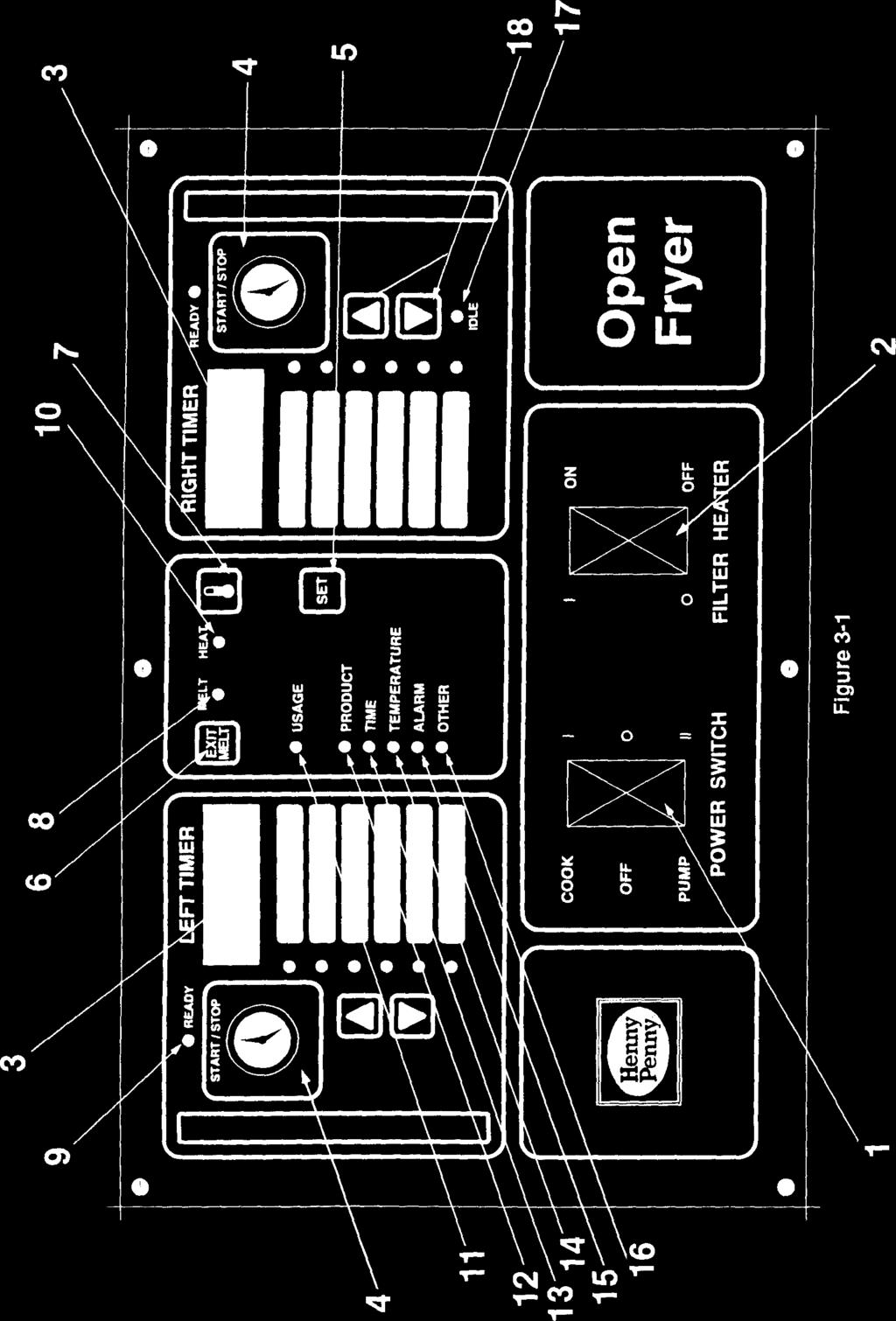
10 SECTION 3. OPERATION 3-1. INTRODUCTION This section provides operating procedures for the Henny Penny OE Read sections 1, 2, and 3 and all instructions before operating the fryer OPERATING CONTROLS Figures 3-1 through 3-8 identify and describe the function of all operating controls and components. Page Fig. Item Description Function No. No. No Cook/Off/Pump This three position rocker type switch controls the power Switch to the fryer when in the cook position. When in the pump position, power is then applied to the filter pump motor Filter Heaters This machine is equipped with an optional strip heater that the operator must manually turn on and off. The indicator will illuminate when power is applied and will melt any solidified shortening that may have accumulated in the filter pump lines. FLAMMABLE Use filter heater only long enough to melt the solidified shortening in lines. The heater must not be left unattended or fire could result Digital Display The digital display shows the shortening temperature, as well as the timer countdown in the cook cycle. The temperature of the shortening can be determined by depressing the temperature button. If the temperature is below 250 F, the digital display will read "LO". If the temperature exceeds 390 F, the display will read "HI". Any temperature between these two settings will be displayed Timer Button The right timer can be activated or reset by gently pressing the timer button. The same holds true for the left timer button. The left display shows the left timer information and the right display shows the information for the right timer. 3-1
11 3-2. OPERATING CONTROLS (Continued) Page Fig. Item Description Function No. No. No Set Button The set button is used to set the cook cycles and to enter the special program modes Exit Melt Button The exit melt button is used to bypass the melt cycle. By pressing and holding the exit melt button for 5 seconds, the heat comes on continuously Temperature By pressing the temperature button (indicated by ther- Button mometer), the actual shortening temperature will show on the left display and the setpoint temperature on the right display Melt LED When the melt LED is flashing, the fryer is in the melt cycle. When the temperature of the shortening reaches approximately 250 F, the melt LED will go off and automatically switch to the cook cycle. FLAMMABLE When using new shortening, it is recommended to melt the shortening on an outside source before placing shortening in the frypot. Unless elements are completely covered in shortening, fire or damage to the frypot could result Ready LED The ready LED illuminates when the temperature of the shortening is near the setpoint temperature. (It flashes if the temperature is 5 F more than the setpoint temperature.) Heat LED The heat LED illuminates when the heat comes on Usage LED The usage LED flashes slowly when the set button is pressed and held for 2 seconds. The number of loads cooked of a selected product can be obtained at this time. If the set button is pressed and held for 10 seconds the usage LED flashes at a fast rate and the usage can be reset to 0 by pressing the timer button for the desired side Product LED The product LED flashes while in the program modes, and a new product can be selected at this time. 3-2
12 3-2. OPERATING CONTROLS (Continued) Page Fig. Item Description Function No. No. No Time LED The time LED flashes while in the program mode and a new fry time can be programmed Temperature LED The temperature LED flashes while in the program mode and the setpoint temperature can be programmed Alarm LED The alarm LED flashes while in the program mode. Up to four alarms can be programmed in a cook cycle Other LED The other LED flashes while in the high level program mode and special program modes only. Several parameters can be programmed at this time Idle LED The idle LED illuminates when the right timer up and down button is pressed for 2 seconds. The indicator passes through the other product LEDs to the idle LED. The control will then regulate the shortening temperature at a lower programmed temperature Up and Down 2 sets of up and down buttons (denoted as triangles) Buttons are on the control. These buttons are used in programming and product selection. A product is selected by pressing and holding either the up or down button for 2 seconds. To select both the right and left products at the same time the programmed setpoint temperatures must be the same Fuses The fuses, located on the panel behind door, are protective devices that break the circuit when the current exceeds the rated value. The fuses provide overload protection for the control panel High Limit Reset This manual reset lever, located on the panel behind door, Lever must be pushed down in the event the high limit trips. This lever will manually reset the high limit Contactors The contactors are the relays that route power to the heating elements. One relay coil is in series with the high limit temperature control, and the other relay coil is in series with the heat control circuit Fan The fan's function is to eliminate any heat build-up behind the control panel. 3-3
13 3-2. OPERATING CONTROLS (Continued) Page Fig. Item Description Function No. No. No Temperature probe The temperature probe, located behind the control panel, determines the shortening temperature Drain Interlock The drain interlock switch is a microswitch that provides Switch protection for the heating elements in case an operator drains shortening from the frypot while the power switch is on. The drain switch is designed to automatically shut off the control system when the drain valve is opened. FLAMMABLE Is is recommended to turn all power off before opening drain valve, or fire could result Drain Valve The drain valve is a 2-way ball valve and is normally in the closed position. Turn the handle to the open position to drain the shortening from the frypot. Open the drain valve slowly to eliminate splashing of hot shortening. Severe burns could result Filter Valve The filter valve is a 2-way ball valve which operates in conjunction with the filtering system. With the handle in the open position and the main power switch in the pump position, this valve directs the filtered shortening from the filter drain pan back into the frypot Filter Union The filter union connects the filter assembly to the filter pump. It is easily disconnected to allow removal of the filter and filter drain pan. 3-4
14 3-2. OPERATING CONTROLS (Continued) Page Fig. Item Description Function No. No. No Filter Drain Pan The removable filter drain pan houses the filter and catches the shortening when it is drained from the frypot. It is used to remove and discard the shortening when the shortening needs to be replaced. HOT SURFACE Use protective gloves or cloth to prevent burns. The drain pan will be hot Filter Rinse Hose The filter rinse hose is used to rinse food particles from and Quick- the frypot into the filter drain pan. This hand-held hose is Disconnect attached to a quick-disconnect. Use extreme caution when operating the filter rinse hose. Refer to "Filtering Procedures" in this manual for proper operation, or burns could result. 3-5

15 3-6
16 Figure 3-2 Figure 3-3 Figure
17 Figure 3-5 Figure 3-6 Figure 3-7 Figure
18 3-3. FILLING OR ADDING SHORTENING It is recommended that a high quality frying shortening be used in the OE-100. Some low grade shortenings have a high moisture content and will cause foaming and boiling over. The Henny Penny OE-100 requires 65 pounds of shortening. It has a level indicator line marked on the rear of the pot wall, which shows the heated shortening at the proper level. Cold shortening should be below the bottom of the level indicator. The shortening will expand when heated. Maintain hot shortening at level indicator line or fire could result. Shortening and all metal parts that are in contact with the shortening are extremely hot. We recommend using protective gloves when in contact with metal parts OPERATING CONTROLS AND PROCEDURES The Henny Penny Open Fryer with dual timers contains a solid state control of both cooking temperature and time. The following is a brief description of the operating procedure. 1. Be sure the drain valve and filter valve are in the closed position. 2. Fill frypot with shortening. FLAMMABLE When using new shortening, it is recommended to melt the shortening on an outside source before placing shortening in the frypot. Unless elements are completely covered in shortening, fire or damage to the frypot could result. 3. Move power switch to the POWER position. Unit will automatically go into the melt cycle. When shortening temperature has reached approximately 250 F, melt light will extinguish and unit will go into cook cycle. At the end of each day, the cover must be on frypot when not in operation to avoid shortening contamination. 3-9
19 3-4. OPERATING CONTROLS AND PROCEDURES The melt cycle may be bypassed, if desired, by pressing and holding the Exit Melt button for 5 seconds. The control will go directly to the cook cycle. FLAMMABLE Do not bypass the melt cycle unless enough shortening has melted to completely cover all of the heating elements. If melt cycle is bypassed before all heating elements are covered, excessive smoking of the shortening or a fire will result. The temperatures and times are preset from the factory and the two timers operate independently. They may be set, started, or stopped without affecting each other. 4. Completely stir shortening to stabilize the temperature throughout the frypot. 5. When shortening temperature has reached set point, ready light will illuminate, indicating to the operator they may drop product. 6. Lower basket with product into frypot and lightly depress timer button. Countdown will begin. 7. When cook cycle is complete, an alarm will sound and the display will flash "done". Press timer button to stop alarm. 8. Lift basket to allow product to drain. 9. If a hold time is programmed, and the timer button is pushed, the timers will automatically start counting down in a hold cycle. 10. At the end of the hold cycle an alarm sounds. Press the timer button to stop the alarm. 3-10
20 3-5. USAGE REVIEW OPERATION Usage review enables the operator to review the number of loads of the products cooked, either daily or accumulated count. 1. Push the Set button for 2 seconds until the Usage LED flashes. 2. The LED beside the selected product shows the operator which product to be reviewed. To select a product, press the up and down buttons. When all LEDs are lit, all product usages are shown. 3. The left display shows either "daily" or "accu". The right display shows the usage. Push the Set button to change between daily or accumulated. 4. Push and hold Set button to exit usage review USAGE REVIEW RESET 1. Press and hold the Set button for ten seconds. The control will beep 3 times and the Usage LED will flash at a fast rate. 2. Select product and daily, or accumulated type, as described above. Push right timer button to clear displayed usage count. Daily usage is automatically cleared when power is turned off. 3. Push and hold Set button to exit usage review FILTERING OF SHORTENING Frying breaded food requires frequent filtering. Taste the cold shortening every day for flavor. Watch the shortening for foaming during cook cycles. Discard the shortening as soon as it shows signs of foaming. Clean the frypot as follows each time the shortening is changed or filtered: 1. Turn the main power switch to the OFF position. Remove and clean the fry basket in soap and water. Rinse thoroughly. The best results are obtained when the shortening is filtered at the normal frying temperature. 3-11
21 3-7. FILTERING OF SHORTENING (Continued) 2. Use a metal spatula to scrape any build-up from the sides of the frypot. Do not scrape heating element. Position the filter drain pan properly under the drain valve to prevent splashing of hot shortening. Use protective gloves or cloth when draining hot shortening from frypot, or severe burns could result. 3. Open the drain valve very slowly, half a turn at first and then slowly to the full open position. This will prevent excessive splashing of the hot shortening as it drains into the filter drain pan. 4. As the shortening drains from the frypot, use brushes to clean the sides of the frypot and the heating elements. 5. When all of the shortening has drained, scrape or brush the sides and the bottom of the frypot. 6. Rinse the frypot as follows: a. Close the drain valve. b. Open the filter valve. c. Move the main power switch to the PUMP position. Fill frypot 1/3 full, then turn off pump. If there are air bubbles coming up in the shortening, it is possible that the filter union on the filter tube line is not tightened properly. If so, turn off the pump and use protective gloves to tighten the union. HOT SURFACE Use protective glove or cloth when tightening filter union. This union will be hot, and severe burns could result. d. Wash down and scrub the sides of the frypot. e. After the sides and bottom are cleaned, open the drain valve. 3-12
22 3-7. FILTERING OF SHORTENING (Continued) 7. When using the filter rinse hose on your fryer, the following cleaning procedure may be used: a. Attach the filter rinse hose with its quick-disconnect fitting to the male fitting inside the door next to the filter valve handle. To do this, slide back the spring ring on the female side of the quick-disconnect fitting and let it snap into place over the male half of the fitting. b. Make sure the hose nozzle is pointed down into the bottom of the frypot. Close the filter valve and move the main power switch to the PUMP position. Hold nozzle carefully to avoid excessive splashing of hot shortening, or burns could result. c. Rinse the frypot interior. Especially work on hard-to-clean areas, like the frypot bottom. Clean around heating elements. d. After sufficient rinsing with shortening, close the drain valve. e. Turn the main power switch to the OFF position. TURN OFF POWER ONLY CONNECT AND DISCONNECT THE FILTER RINSE HOSE WHEN THE MAIN POWER SWITCH IS IN THE OFF POSITION. FAILURE TO DO THIS WILL RESULT IN SEVERE BURNS FROM HOT SHORTENING SPRAYING FROM THE MALE FITTING. ALSO, USE A DRY CLOTH OR PROTECTIVE GLOVE TO AVOID BURNS. f. Detach the hose. Raise the fitting end of the hose high for a minute to allow the remaining shortening in the hose to drain into the frypot. 8. Pump all of the shortening out of the filter drain pan and back into the frypot. 3-13
23 3-7. FILTERING OF SHORTENING (Continued) 9. When the pump is pumping air only, the shortening in the frypot will appear to be boiling. Close the filter valve first and then move the main power switch from PUMP to OFF. This will keep the filter pump and lines from filling up with shortening. 10. Check the level of the shortening in the frypot. Add fresh shortening if necessary, until it reaches the level indicator line on the rear wall of the frypot. Approximately 10 to 12 filterings can be made with one filter paper envelope, depending on several conditions: the quantity and type of product fried and filtered, the type of breading used, and the amount of crumb accumulation left inside the filter drain pan. When the filter screen assembly and filter paper become clogged and the pumping flow rate slows down, clean the filter screen assembly and change the filter envelope. 11. If frying is to be continued at this time, move the main power switch back to the POWER position, and allow time for reheating of the shortening FILTER PUMP PROBLEMS The following steps will help prevent filter pump problems: 1. Make certain the filter paper envelope is properly installed over the filter screens. Make sure the open end of the envelope is properly folded over and clamped in place with the retaining clips so that the envelope is sealed and crumbs cannot enter. 2. Make sure the filter valve is kept closed at all times during frying. 3. Make sure all the shortening has been pumped from the filter lines and the pump by allowing the filter pump motor to run until the shortening in the frypot appears to be bubbling or boiling. 3-14
24 3-8. FILTER PUMP PROBLEM (Continued) 4. If the filter pump motor overheats, a thermal protector shuts the motor off. Wait about 5 minutes, then manually reset the button on the rear of the motor. This button takes some effort to reset. A screwdriver can be used to press against the button to reset. TURN OFF To prevent burns caused by splashing shortening, the fryer s main power switch must be in the OFF position before resetting the filter pump motor s manual reset protection device. Reset Button 3-9. CHANGING THE FILTER ENVELOPE The filter envelope should be changed after filterings or whenever it becomes clogged with crumbs. Proceed as follows: 1. Move the main power switch to the OFF position. 2. Disconnect the filter union and remove the filter drain pan from beneath the frypot. HOT SURFACE The filter union may be hot. Use protective gloves or cloth to prevent burns. To avoid burns caused by splashing of hot shortening, use protective gloves or cloth. 3. Lift the filter screeen assembly from the filter drain pan. 4. Wipe the shortening and crumbs from the filter drain pan. Clean the filter drain pan with soap and water. Thoroughly rinse with hot water. 5. Unthread the standpipe from the filter screeen assembly. 6. Remove the crumb catcher and clean thoroughly with soap and water. Rinse thoroughly with hot water. 3-15
25 3-9. CHANGING THE FILTER ENVELOPE (Continued) 7. Remove the filter clips and discard the filter envelope. 8. Clean the top and bottom filter screen with soap and water. Rinse thoroughly with hot water. Be sure that the filter screens, crumb catcher, filter clips, and the standpipe are thoroughly dry before assembly of filter envelope as water will dissolve the filter paper. 9. Assemble the top filter screen to the bottom filter screen. 10. Slide the screens into a clean filter envelope. 11. Fold the corners in and then double fold the open end. 12. Clamp the envelope in place with the two filter retaining clips. 13. Replace the crumb catcher screen on top of the filter paper. Screw on the standpipe assembly. 14. Place complete filter screen assembly back into filter drain pan and slide pan back into place beneath the fryer. 15. Connect the filter union by hand. Do not use a wrench to tighten. 16. The fryer is now ready to operate CLEANING THE FRYPOT After the initial installation of the fryer, as well as before every change of shortening, the frypot should be thoroughly cleaned as follows: Melt bypass should be in operation. Refer to paragraph 3-4, "Operating Controls and Procedures", on bypassing the melt cycle
26 3-10. CLEANING THE FRYPOT (Continued) 1. Turn the main power switch to OFF. Position the filter drain pan properly under the drain valve to prevent splashing of hot shortening. Use protective gloves or cloth when draining hot shortening from frypot, or severe burns could result. 2. If hot shortening is present in the frypot, it must be drained by slowly opening the drain valve handle one half turn. Leave for a few minutes, then slowly open the valve to the full open position. 3. Close the drain valve. Discard the shortening in the filter drain pan. Then install the filter drain pan under the fryer, leaving out the filter screen assembly. 4. Fill the frypot to the level indicator with hot water. Add 4 to 6 ounces of fryer cleaner to the water and mix thoroughly. The fry basket can be placed inside frypot for cleaning. ALWAYS WEAR CHEMICAL SPLASH GOGGLES OR FACE SHIELD AND PROTECTIVE RUBBER GLOVES WHEN CLEANING THE FRYPOT AS THE CLEANING SOLUTION IS HIGH IN ALKALINE. SPLASHING OR OTHER CONTACT WITH THE SOLUTION WILL RESULT IN BURNS TO EYES OR SKIN. BEFORE USE, CAREFULLY READ THE INSTRUCTIONS ON THE CLEANER. IF THE SOLUTION COMES IN CONTACT WITH YOUR EYES, RINSE THOROUGHLY WITH COOL WATER AND SEE A PHYSICIAN IMMEDIATELY. 5. Turn the main power switch to the POWER position and set the temperature to 200 F. The melt bypass must be used. 6. When the cleaning solution starts a rolling boil, immediately move the main power switch to OFF
27 3-10. CLEANING THE FRYPOT (Continued) Watch cleaning solution constantly to make sure it does NOT boil over, causing damage to controls. 7. Repeat steps 5 and 6 and bring the solution to a boil. Repeat at least 5 times. 8. Let the cleaning solution stand for 15 to 20 minutes with the power off. 9. Using the fryer brush (never use steel wool), scrub the inside of the frypot. 10. After boiling and cleaning, turn off the main power switch. Open the drain valve and drain the cleaning solution from the frypot into the filter drain pan and discard. 11. Replace the empty filter drain pan, close the drain valve, and refill the frypot with plain hot water to proper level. 12. Add approximately 8 ounces of distilled vinegar and bring the solution to a boil. 13. Using a clean brush, scrub the interior of the frypot. This will neutralize the alkaline left by the cleaning compound. 14. Drain the vinegar rinse water and discard. 15. Rinse down the frypot using clean, hot water. 16. Completely dry the filter drain pan and the frypot interior. Make sure the inside of the frypot, the drain valve opening, and all the parts that will come in contact with the new shortening are as dry as possible, because water dissolves the filter paper. 17. Replace the clean filter screen assembly in the filter drain pan and install under fryer. 18. Refill the fryer with fresh shortening

28 3-11. PREVENTIVE MAINTENANCE The cooling fan on the OE-100 reduces the amount of heat behind the control panel. If the PC board gets too hot, "E-4" shows on the display, and shuts the heat off to the fryer. Too much heat can damage the PC boards on the control panels so it s important that the cooling fan operates properly and has good air flow. To prevent an "E-4" reading, clean the fan guard as follows: ONCE A MONTH: 1. Turn power switch to the "OFF" position. 2. Open door to bottom of fryer. 3. Locate metal fan guard situated in the left front, under the control panel. 4. Clean any lint and dirt from fan guard ERROR CODES Display Cause Correction E4 PC board too hot. Clogged Check fan guard per section 3-11, or replace or faulty cooling fan. faulty cooling fan. E5 Shortening too hot Unplug unit, or turn off circuit breaker to unit. If display still shows E5, have the heating and high limit circuits checked. E6 Temperature probe failure Unplug unit, or turn off circuit breaker to unit. If display still shows E6, check temperature probe connection at board. If connection is good, have temperature probe replaced. E10 High temperature limit Reset high temperature limit by manually tripped or faulty pushing lever, behind door. (see Figure 3-2). If high limit does not reset, replace high limit. E41, E50, Control errors Unplug unit, or turn off circuit breaker to E51, E53 unit. If display still shows an error, reinitialize the control (see Section 4-4). If error still persists, change the control panel. 3-19
29 SECTION 4. PROGRAMMING The controls have three programming levels: a low level mode, a high level mode, and a special program mode. In each level, pressing the Set button advances through the programmable items. Program mode can be entered any time except during an alarm. The left display describes the item being programmed. The right display shows the item setting and can be changed by pressing the right Up and Down buttons LOW LEVEL PROGRAM MODE The Low Level Program Mode allows the operator to program the time, temperature, and set up to 4 alarms for the selected product. 1. Press and hold Set and Temp buttons for at least 5 seconds. A tone will sound, and the left display shows "Slct" and the right display shows "Prod". The Product LED also flashes. 2. Press either the left or right Up and Down buttons to select a product to program, and the LED next to the desired product will be lit. 3. Press the Set button and the Time LED flashes. The left display shows "Fry" and the right display shows the cook time. Pressing the right Up and Down buttons adjusts the cook time. 4. Press the Set button and the Time LED continues to flash. The left display shows "Hold", the right display shows the hold time and can be adjusted with the right Up and Down buttons. 5. Press the Set button and the Temperature LED flashes. The left display shows "Fry", the right display shows the setpoint, and can be adjusted with the right Up and Down buttons. 6. Press the Set button and the Alarm LED flashes. The left display shows "AL 1, the right display shows the alarm time and can be adjusted with the right Up and Down buttons. 7. Repeat step 6 for alarms 2, 3, and
30 4-1. LOW LEVEL PROGRAM MODE (Continued) 8. Press the Set button and the Alarm LED flashes. The left display shows "HdAl" and the right display shows the hold alarm setting, and can be adjusted with the right Up and Down buttons. 9. Press Set button and the Product LED flashes. Push either Up or Down buttons to select another product to program, or press and hold the Set button to exit program mode HIGH LEVEL PROGRAM MODE The High Level Program Mode allows the operator to program load compensation, load anticipation, proportional control, filter cycle for the selected product, and the idle parameters. 1. While in the low level mode, push and hold the Set and Exit Melt buttons for 5 seconds. The beeper will sound and the left display will show " Slct" and the right display will show "Prod". The Product LED also flashes. 2. Press either the right or left Up and Down buttons to select a product to program. 3. Press Set button and the Other LED flashes. The left display shows "LdCo", and the right display shows load compensation setting, and can be adjusted with the right Up and Down buttons. 4. Press the Set button and the Other LED continues to flash. The left display shows "PC", the right display shows the proportional control setting, and can be adjusted with the right Up and Down buttons. 5. Press the Set button and the Other LED continues to flash. The left display shows "LdAn", and the right display shows load anticipation setting, and can be adjusted with the right Up and Down buttons. 6. Press the Set button and the Other LED continues to flash. The left display shows "Filtr", and the right display shows filter cycles setting, and can be adjusted with the right Up and Down buttons. 4-2
31 4-2. HIGH LEVEL PROGRAM MODE (Continued) 7. Press the Set button and the Product LED flashes. Press either right or left Up and Down buttons to select another product to program. Press and hold the Set button to exit the program mode. 8. Also, with the Product LED flashing, pressing the right Up and Down buttons accesses the Idle Mode parameters. The idle LED flashes, the left display shows "Auto", and the right display shows the auto idle time. Adjust the idle parameters with the right Up and Down buttons, or disable the auto idle to "OFF" (see Section 6-3) IDLE PROGRAMMING The Idle Mode must be enabled for the operator to access this mode. 1. While in the high level program mode, and the Product LED is flashing, press the right Up and Down buttons to select the idle mode items. The Idle LED will be flashing. 2. Press Set button and the Time LED flashes. The left display shows "Auto", and the right display shows auto idle time. Adjust the auto idle time with the right Up and Down buttons, and to disable the auto idle feature, set time to "OFF". 3. Press Set button and the Temperature LED flashes. The left display shows F or "C", and the right display the idle temperature setpoint, which can be adjusted with the right Up and Down buttons. 4. Press Set button and the Product LED flashes. Press either the left or right Up and Down buttons to select another product to program, or press and hold the Set button to exit program mode. 4-3
32 4-4. SPECIAL PROGRAM MODE The Special Program Mode allows the operator to program Fahrenheit or Celsius, temperature probe calibration, alarm duration, hold duration, to initialize the program, or to put the control through an 1/0 test. 1. While in high level program mode, press and hold Exit Melt and Temp buttons until the buzzer sounds, and the left display shows "SPCL" and the right display shows "Prog". Then release the buttons and the display will show software version, then deg. 2. Also, the Special Program Mode can be accessed by pressing and holding the Set button and turning the power switch on. 3. Once in the Special Program Mode, press the right Up and Down buttons to select Fahrenheit ( F) or Celsius ( C). 4. Press Set button and the left display shows "Prob", and then "calib". The temperature probe calibration then can be adjusted with the right Up and Down buttons. 5. Press the Set buttons and the left display shows "AL", then "dur". The timer alarm duration can be adjusted with the right Up and Down buttons. The duration shows in right display. 6. Press Set button and the left display shows "Hold", then "dur". The hold alarm duration can be adjusted by the right Up and Down buttons. The right display shows the duration. 7. Press Set button and the left display shows "init", and the right display shows "sys". Push and hold the right Up and Down buttons for 5 seconds to initialize all settings. Special Program Mode is automatically exited if initialization is done. 8. Press Set button to skip setting initialization and the left display shows "10", right shows "test". The displays will then go blank and by pressing all buttons, enables all LEDs and displays. Pressing TEMP button turns on heat. 9. Press and hold Set button to exit Special Program Mode. 4-4
33 G L O S S A R Y HENNY PENNY OPEN FRYERS air valve airflow switch (gas fryers only) blower (gas fryers only) breading burner assembly (gas fryers only) burner tubes (gas fryers only) carrier casters cleaning solution cold zone cook cycle cooking load counterweight counterweight assembly cover cracklings crumb catcher a valve on the eight head fryer that allows air into the filter lines when the pump is on in the mixing mode on eight head fryers a switch on the eight head fryer that senses the amount of airflow coming from the blower; if the airflow falls below a certain level, the switch cuts power to the gas control valve that shuts down the burners located on the rear of a gas fryer, the blower pulls flue gases out of the flue and provides the proper amount of air to the burner tubes for efficient combustion a flour and seasoning mixture used to coat the product prior to frying an assembly on gas fryers that houses the pilot light which ignites the gas that heats the fryer the tubes through which heated air is forced to heat the shortening a wire frame inside the eight head frypot that holds five racks of product during the cook cycle the wheels on bottom of the fryer that allow the unit to roll; casters should be locked when unit is in use and not being moved; casters may be adjusted to help level the fryer an agent used to clean the frypot; see recommended cleaning procedures an area in the bottom of the frypot where shortening is cooler than the area above; the zone allows the crumbs to settle without burning a programmed cycle that cooks a particular product at a preselected temperature and for a preselected time the amount of product cooked during a cook cycle the weights shipped with the fryer that, when installed in the counterweight assembly, enable the eight head fryer lid to lift easily an assembly of weights and cables that enable the eight head fryer lid to lift easily a protective lid for the frypot when fryer is not in use the crumbs of breading that come off the product during a cook cycle the part of the filter assembly on four head fryers that filters crumbs out of the shortening before the shortening is pumped back into the frypot 202 G-1
34 data plate drain handle drain interlock switch drain valve dumping table fill lines filter clips filter drain pan filter envelope filter heater switch filter pan dolly filter pump motor filter screen assembly filter union filter valve flame sensors (gas fryers only) fryer brush frypot frypot collar a label or plate located on the right side panel of the fryer that indicates the fryer type, serial number, warranty date, and other information the handle used to open and close the drain valve a microswitch that automatically shuts off the fryer heat in the event the drain valve is inadvertently opened while the fryer power switch is in the ON position a valve that allows the shortening to drain from the frypot into the filter drain pan; the fryer power switch should be in the OFF position before the drain valve is opened; the drain valve should remain closed at all other times a table onto which the cooked product is dumped after removal from the fryer frypot the four lines marked on the interior real wall of the frypot that show the proper shortening level (also referred to as level indictor lines) the clips are the part of the filter screen assembly that holds the filter envelope closed a pan that slides under the fryer into which shortening is drained a fiber envelope into which the filter screen is placed; the end of the envelope is folded and held closed with filter clips; a part of the filter screen assembly control panel switch that activates the strip heater (Model OE-100 only) an optional transport cart for the filter drain pan the motor that powers the filtering system an assembly that filters the shortening as it is pumped from the frypot; the assembly is made up of two filter screens, a filter envelope, two filter clips, and a crumb catcher (Note: eight head fryers have two filter screens with no crumb catcher) the threaded connection between the fryer and the filter system that can be connected or released without tools the valve that must be opened to pump shortening back into the frypot during the filter cycle (Models OE-100, 320, and 340) the sensors that shut off the gas supply to gas fryers if the pilot lights go out or do not light a brush included with the fryer used to scrub the inside of the frypot the interior portion of the fryer that holds the shortening and the product while cooking the top flat surface area around the fryer lid G-2 202
35 gas control valve (gas fryers only) gas valve knob (gas fryers only) gas pressure regulator (gas fryers only) heat indicator heating elements high limit ignition modules L-shaped brush landing table level indicator lines lid assembly lid handle lid latch manual reset lever manual shutoff valve (gas fryers only) melt cycle pilot orifice (gas fryers only) pilot light (gas fryers only) an automatic dual controller that controls gas to both pilot lights and gas pressure to burners on fryers; if either pilot light goes out, the controller shuts off the gas to the other pilot light the knob that opens and closes the gas control valve a device located on the gas control valve that regulates the gas pressure; the pressure specifications are preset at the factory the light that illuminates when the shortening is being heated; the light goes off when the preset shortening temperature has been achieved the coils located inside the frypot on electric fryers that heat the shortening a temperature control that opens and shuts off the heat to the frypot if it senses shortening temperature in excess of 420 F (212 C) two modules that send electrical energy to the spark igniters that ignite the pilot lights on gas fryers a brush included with the fryer that is used to clean around the burner tubes and heating elements another name for a dumping table (see dumping table) the lines marked on the interior real wall of the frypot that show the proper shortening level (also referred to as fill lines) an assembly comprised of lid, lid handle, and lid latch which raises and lowers product into shortening on eight head fryers a handle that is attached to the lid and is used to lower the lid into contact with the frypot; the handle is then pulled forward and pushed down to lock the lid in place (see lid latch) a mechanical catch on the front of the fryer lid that engages a bracket located on the front of the frypot; the latch holds the lid down resets high limit (OE-100 only) a valve located between the fryer and the wall that shuts off the flow of gas from the supply line; this is not the main shutoff valve for the store a heat mode that cycles on and off to slowly melt the shortening when the power switch is on and the shortening temperature is below a certain temperature; the melt cycle prevents scorching of the shortening a controlled opening for the pilot light located on the burner assembly a small flame that remains burning even when the fryer is not in use; the flame ignites the gas when the fryer is turned on 202 G-3
36 power/pump switch product rack setpoint shortening mixing system shortening shuttle sift breading spark igniters (gas fryers only) standpipe standpipe assembly straight brush strip heater temperature probe thermal protector a three-way switch located on the front control panel of the fryer that serves as an off/on switch and a filter switch a food item cooked in the fryer the wire grid that slides into the carrier to hold product during the cook cycle a preset cooking temperature; the setpoint is a programmable feature an automatic system on eight head fryers hat periodically uses the filter pump to mix the shortening in the frypot to prevent an accumulation of moisture to minimize the boiling action in the frypot optional equipment used for shortening disposal the process of removing clumps from breading the igniters that create a spark to ignite the pilot lights on gas fryers (see ignition modules) the pipe through which oil is pumped back into the frypot after the filtering process is complete the pipe and fittings that are part of the shortening filtering process a brush that is included with the fryer that is used to clear the drain in the bottom of the frypot keeps the filter lines free of solidified shortening when the filter heater switch is turned on (Model OE-100 only) a round probe that is located in the inside of the frypot that measures the temperature of the oil in the frypot; the probe communicates with the control panel overheat protection swtich for the filter motor that must be manually reset if tripped G-4 202
Henny Penny Island Warmer Model HMI-103 Model HMI-105 TECHNICAL MANUAL
 Henny Penny Island Warmer Model HMI-103 Model HMI-105 TECHNICAL MANUAL THIS PAGE INTENTIONALLY LEFT BLANK. Section TABLE OF CONTENTS Page Section 1. TROUBLESHOOTING... 1-1 1-1. Introduction... 1-1 1-2.
Henny Penny Electronic Bun Warmer Model BW-1 Model BW-4 Model BW-4 Model BW-4/3 Model BW-6 Model BW-8
 Henny Penny Electronic Bun Warmer Model BW-1 Model BW-4 Model BW-4 Model BW-4/3 Model BW-6 Model BW-8 SERVICE MANUAL LIMITED WARRANTY FOR HENNY PENNY EQUIPMENT Subject to the following conditions, Henny
Henny Penny Island Warmer Model HMI-103 Model HMI-105 TECHNICAL MANUAL
 Henny Penny Island Warmer Model HMI-103 Model HMI-105 TECHNICAL MANUAL Section TABLE OF CONTENTS Page Section 1. TROUBLESHOOTING... 1-1 1-1. Introduction... 1-1 1-2. Safety... 1-1 1-3. Troubleshooting...
Henny Penny Blast Chiller/Freezer Models BCC/BCR-140 Models BCC/BCR-175 Models BFR/BCR-350
 Henny Penny Blast Chiller/Freezer Models BCC/BCR-140 Models BCC/BCR-175 Models BFR/BCR-350 TECHNICAL MANUAL Section TABLE OF CONTENTS Page Section 1. TROUBLESHOOTING... 1-1 1-1. Introduction... 1-1 1-2.
OPERATOR S MODEL OFE-321 OFE-322 OPEN FRYER REGISTER WARRANTY ONLINE AT
 OPERATOR S M A N U A L OPEN FRYER MODEL OFE-321 OFE-322 REGISTER WARRANTY ONLINE AT WWW.HENNYPENNY.COM TABLE OF CONTENTS Section Page Section 1. INTRODUCTION...1-1 1-1. Introduction...1-1 1-2. Proper
OPERATOR S MODEL HHC-901 HHC-904 HEATED HOLDING CABINET REGISTER WARRANTY ONLINE AT
 OPERATOR S M A N U A L HEATED HOLDING CABINET MODEL HHC-901 HHC-904 REGISTER WARRANTY ONLINE AT WWW.HENNYPENNY.COM TABLE OF CONTENTS Section Page Section 1. INTRODUCTION... 1-1 1-1. Heated Holding Cabinet...
OPERATOR S MODEL HMI-103 HMI-105 ISLAND WARMER REGISTER WARRANTY ONLINE AT
 OPERATOR S M A N U A L ISLAND WARMER MODEL HMI-103 HMI-105 REGISTER WARRANTY ONLINE AT WWW.HENNYPENNY.COM TABLE OF CONTENTS Section Page Section 1. INTRODUCTION... 1-1 1-1. Island Warmers... 1-1 1-2.
OPERATOR S MODEL HCN-5 HHC-136 HEATED HOLDING CABINET REGISTER WARRANTY ONLINE AT
 OPERATOR S M A N U A L HEATED HOLDING CABINET MODEL HCN-5 HHC-136 REGISTER WARRANTY ONLINE AT WWW.HENNYPENNY.COM TABLE OF CONTENTS Section Page Section 1. INTRODUCTION... 1-1 1-1. Heated Holding Cabinet...
OPERATOR S MODEL CW-216 CW-114 DISPLAY COUNTER WARMER REGISTER WARRANTY ONLINE AT
 OPERATOR S M A N U A L DISPLAY COUNTER WARMER MODEL CW-216 CW-114 REGISTER WARRANTY ONLINE AT WWW.HENNYPENNY.COM TABLE OF CONTENTS Section Page Section 1. INTRODUCTION... 1-1 1-1. Display Counter Warmer...
OPERATOR S. MODEL Computron 2000 PRESSURE FRYER REGISTER WARRANTY ONLINE AT
 OPERATOR S M A N U A L PRESSURE FRYER MODEL 500 600 Computron 2000 REGISTER WARRANTY ONLINE AT WWW.HENNYPENNY.COM This manual should be retained in a convenient location for future reference. A wiring
OPERATOR S MODEL MPC-21L MPC-222 MULTIPURPOSE PASS-THRU HOLDING CABINET. Read instructions before operating the appliance
 OPERATOR S M A N U A L MULTIPURPOSE PASS-THRU HOLDING CABINET MODEL MPC-21L MPC-222 REGISTER WARRANTY ONLINE AT WWW.HENNYPENNY.COM Read instructions before operating the appliance TABLE OF CONTENTS Section
OPERATOR S MODEL OFE/OFG-341 OFE/OFG-342 OEA/OGA-341 OEA/OGA-342 HIGH VOLUME OPEN FRYER REGISTER WARRANTY ONLINE AT
 OPERATOR S M A N U A L HIGH VOLUME OPEN FRYER MODEL OFE/OFG-341 OFE/OFG-342 OEA/OGA-341 OEA/OGA-342 REGISTER WARRANTY ONLINE AT WWW.HENNYPENNY.COM This manual should be retained in a convenient location
OPERATOR S MODEL HC-5 HC-15 HHC-900 HHC-902 HHC-903 HHC-906 HHC-908 HEATED HOLDING CABINET REGISTER WARRANTY ONLINE AT
 OPERATOR S M A N U A L HEATED HOLDING CABINET MODEL HC-5 HC-15 HHC-900 HHC-902 HHC-903 HHC-906 HHC-908 REGISTER WARRANTY ONLINE AT WWW.HENNYPENNY.COM TABLE OF CONTENTS Section Page Section 1. INTRODUCTION...
OPERATION MANUAL KLEENSCREEN FILTRATION SYSTEM SUPPLEMENT INSTRUCTION MANUAL FOR: Gas Fryer Models. Electric Fryer Models
 OPERATION MANUAL KLEENSCREEN FILTRATION SYSTEM SUPPLEMENT INSTRUCTION MANUAL FOR: Gas Fryer Models GR35F ML-126998 GR45F ML-126999 GR65F ML-135534 GR85F ML-135535 GRD35F ML-126732 GRD45F ML-126735 GRD65F
Autolift Open Fryer. CR-40F & CR-60F Instruction Manual
 Autolift pen Fryer Instruction Manual 735 Rossiter, St-Jean-sur-Richelieu, Quebec, Canada, J3B 8A4 E-Mail : info@resfab.com Website : www.resfab.com 2007-05 TABLE F CNTENTS Page Limited warranty.. 03 Unpacking..
TECHNICAL MANUAL TM... Fryer, Deep-Fat, Electric w/solid State Controls 440 Volt, 60 HZ, 3 Phase NSN:
 TM... TECHNICAL MANUAL MODEL USN-50 DESCRIPTION Fryer, Deep-Fat, Electric w/solid State Controls 440 Volt, 60 HZ, 3 Phase NSN: Commercial & Marine Cooking Equipment Gas & Electric Last Updated September
Henny Penny Humidified Counter Warmer Model HCW-2 Model HCW-3 Model HCW-5 Model HCS-5 Model HCW-8 TECHNICAL MANUAL
 Henny Penny Humidified Counter Warmer Model HCW-2 Model HCW-3 Model HCW-5 Model HCS-5 Model HCW-8 TECHNICAL MANUAL Section TABLE OF CONTENTS Section 1. TROUBLESHOOTING... 1-1 1-1. Introduction... 1-1
FRYMASTER TCF. Chicken Fryer
 Hardee s Food Systems, Inc. FRYMASTER TCF Chicken Fryer EQUIP 501 Chicken Fryer October 1, 1994 CALIBRATION EQUIPMENT and TOOLS Digital Thermometer Flat Blade or Phillips w/immersion Probe Screwdriver
OPERATOR S MODEL CFE-410 CFE-420. OPEN FRYER (Electric) REGISTER WARRANTY ONLINE AT
 REGISTER WARRANTY ONLINE AT") OPERATOR S M A N U A L OPEN FRYER (Electric) MODEL CFE-410 CFE-420 REGISTER WARRANTY ONLINE AT WWW.HENNYPENNY.COM TABLE OF CONTENTS Section Page Section 1. INTRODUCTION... 1-1 1-1 Introduction... 1-1
OPERATOR S M A N U A L OPEN FRYER (Electric) MODEL CFE-410 CFE-420 REGISTER WARRANTY ONLINE AT WWW.HENNYPENNY.COM TABLE OF CONTENTS Section Page Section 1. INTRODUCTION... 1-1 1-1 Introduction... 1-1
GAS RACK OVENS WITH ELECTRONIC OVEN CONTROL
 GAS RACK OVENS WITH ELECTRONIC OVEN CONTROL MODELS DRO2G DRO2GH GAS GAS 701 S. RIDGE AVENUE TROY, OHIO 45374-0001 937-332-3000 www.hobartcorp.com FORM 19202 Rev. D (Dec. 2003) IMPORTANT FOR YOUR SAFETY
Henny Penny Humidified Holding Cabinets Model HHC-980 Model HHC-983 TECHNICAL MANUAL
 Henny Penny Humidified Holding Cabinets Model HHC-980 Model HHC-983 TECHNICAL MANUAL LIMITED WARRANTY FOR HENNY PENNY EQUIPMENT Subject to the following conditions, Henny Penny Corporation makes the following
Henny Penny Display Counter Warmer Model CW-216/CW-114 TECHNICAL MANUAL
 Henny Penny Display Counter Warmer TECHNICAL MANUAL Section TABLE OF CONTENTS Section 1. TROUBLESHOOTING... 1-1 1-1. Introduction... 1-1 1-2. Safety... 1-1 1-3. Troubleshooting... 1-1 Page Section 2.
FR 2 Frymaster Fryer
 FRYERS FR 2 Frymaster Fryer Electric and Gas models using an M2000 Computer Weekly maintenance task FR 2 W1 Clean area behind fryers Bi-weekly maintenance task FR 2 B1 Calibrate fryer Monthly maintenance
PLEASE RETAIN THIS MANUAL FOR FUTURE REFERENCES. This equipment is design engineered for commercial use only
 OWNER S MANUAL INSTALLATION OPERATION MAINTENANCE FRYER SRF-40/50 All equipment manufactured by SIERRA CORP. is for use with the type of gas specified on the rating plate and for installation will be in
Henny Penny Heated Holding Cabinet Model HCH-930 Model HCH-932 TECHNICAL MANUAL
 Henny Penny Heated Holding Cabinet Model HCH-930 Model HCH-932 TECHNICAL MANUAL TABLE OF CONTENTS Section Page Section 1. TROUBLESHOOTING... 1-1 1-1. Introduction... 1-1 1-2. Safety... 1-1 1-3. Troubleshooting...
PRO SERIES GAS FRYERS OWNER S MANUAL
 PRO SERIES GAS FRYERS OWNER S MANUAL MODELS: PF-1 PRO-FRYER, PF2 DUAL PRO-FRYER REVISED OCTOBER, 2009 *PLEASE RETAIN FOR FUTURE REFERENCE This appliance has been tested according to ANSI Z83.116-2009/CSA1.86-2009.
OPERATIONS MAINTENANCE MANUAL
 OPERATIONS MAINTENANCE MANUAL COOK & HOLD OVEN SYSTEMS WITTCO MODEL NUMBERS 1300-AD-SS 1300-AD-SS-SPLIT LIMITED WARRANTY Wittco warrants the Products that it manufactures to be free from defects in materials
Installation and Operation Manual For Electric Fryers. Covering Models SE, SEH, SEM Series
 Installation and Operation Manual For Electric Fryers Covering Models SE, SEH, SEM Series Pitco Frialator, Inc., P.O. Box 501, Jct I-89 & I-93 Concord, NH 03302-0501 509 Route 3A, Bow, NH 03304 (603) 225-6684
OPERATION MANUAL ODS 300 ODS 310
 300 Series Oil Disposal Shuttle OPERATION MANUAL ODS 300 ODS 310 FM07-635J Table of Contents Safety... iii Chapter 1 Introduction...1 1.1 Introduction...1 1.2 Technical Support...1 1.3 Model Configuration
INSTALLATION & OPERATION MANUAL
 INSTALLATION & OPERATION MANUAL EF SERIES ECONOFRY GAS FRYERS MODEL EF3 EF4 EF5 ML-52099 ML-114943 ML-114944 MODEL EF3 For additional information on Vulcan-Hart or to locate an authorized parts and service
CM4-S COMPUTER OPERATION (PROGRAMMED FOR TEXAS CHICKEN) Programming button. Setting up the Fryer for Initial Use
 Programming button. Setting up the Fryer for Initial Use") 1 2 3 4 5 6 7 8 9 10 CM4-S COMPUTER OPERATION Texas Chicken Operation CM4-S computers on fryers prepared for Texas Chicken are specially programmed for use with either the restaurant's chicken or french
1 2 3 4 5 6 7 8 9 10 CM4-S COMPUTER OPERATION Texas Chicken Operation CM4-S computers on fryers prepared for Texas Chicken are specially programmed for use with either the restaurant's chicken or french
INSTALLATION INSTRUCTIONS & USE & CARE GUIDE 06E Series Model 06E Series Model RANGE HOOD LOCATION 1. The range hood must be installed just above the
 INSTALLATION INSTRUCTIONS & USE & CARE GUIDE 06E Series Model 06E Series Model RANGE HOOD LOCATION 1. The range hood must be installed just above the cooktop. 2. The minimum distance from the cooking surface
Part No Revised: October 2004 BUN WARMER. Instruction Manual. Models:8018,8019,8117,8219,8170
 BUN WARMER Instruction Manual Models:8018,8019,8117,8219,8170 Part No. 87794 Revised: October 2004 SAFETY PRECAUTIONS INSTALLATION INSTRUCTIONS Checking Shipment Unpack carton and check thoroughly for
Filtration. General Instructions
 Filtration General Instructions Ultrafryer Systems 302 Spencer Lane P.O. Box 5369 San Antonio, TX 78201 Local: (210) 731-5000 Toll-Free: (800) 525-8130 Fax: (210) 731-5099 Web: www.ultrafryer.com 30A181-Jul2007
CINCINNATI, OH USA
 INSTRUCTION MANUAL Part No. 89731 Revised October 1997 CINCINNATI, OH 45241-4807 USA GAS SAFETY PRECAUTIONS Instructions on what to do when a user smells gas can be obtained from the local gas supplier.
OPERATOR S MANUAL REGISTER WARRANTY ONLINE AT
 Henny Penny Evolution Elite Reduced Oil Capacity Open Fryers (Full Vat Electric) Wendy s Model EEE-153 Model EEE-154 OPERATOR S MANUAL REGISTER WARRANTY ONLINE AT WWW.HENNYPENNY.COM LIMITED WARRANTY FOR
Cool-Touch Deep Fryer / Fondue Maker
 Cool-Touch Deep Fryer / Fondue Maker Use and Care Instructions Model EP64 For information or assistance call 514-842-8691 EURO-PRO Corporation In U.S.: 178 West Service Rd., Champlain, NY 12919 In Canada:
OPERATOR S MODEL HMR-103 HMR-104 HMR-105 HMR-106 HMR-107 HEATED MERCHANDISERS REGISTER WARRANTY ONLINE AT
 OPERATOR S M A N U A L HEATED MERCHANDISERS MODEL HMR-103 HMR-104 HMR-105 HMR-106 HMR-107 REGISTER WARRANTY ONLINE AT WWW.HENNYPENNY.COM TABLE OF CONTENTS Section Page Section 1. INTRODUCTION... 1-1 1-1.
OWNER S MANUAL. FLAT PANEL FIREPLACE HEATER Model Number: Serena (EF202A) WARNING CAUTION
 WARNING CAUTION") FLAT PANEL FIREPLACE HEATER Model Number: Serena (EF202A) OWNER S MANUAL WARNING Read and understand this entire owner s manual, including all safety information, before plugging in or using this product.
FLAT PANEL FIREPLACE HEATER Model Number: Serena (EF202A) OWNER S MANUAL WARNING Read and understand this entire owner s manual, including all safety information, before plugging in or using this product.
Superdryer Dehumidifiers
 Superdryer Dehumidifiers Installation and Operations Manual Read and Save These Instructions Distributed Exclusively By: Air Cleaning Equipment, Inc. Broadway, NC 27505 Phone: 919-258-3330 www.aircleaningequipment.com
CM4-S(t) COMPUTER OPERATION (PROGRAMMED FOR CHURCH S CHICKEN) Programming Key. Setting up the Fryer for Initial Use
 COMPUTER OPERATION (PROGRAMMED FOR CHURCH S CHICKEN) Programming Key. Setting up the Fryer for Initial Use") 1 2 3 4 5 6 7 8 9 10 8700 Line Ave. Shreveport, LA 71106 Service Hotline 800-551-8633 CM4-S(t) COMPUTER OPERATION Church s Chicken Operation CM4-S computers on fryers prepared for Church s Chicken are
1 2 3 4 5 6 7 8 9 10 8700 Line Ave. Shreveport, LA 71106 Service Hotline 800-551-8633 CM4-S(t) COMPUTER OPERATION Church s Chicken Operation CM4-S computers on fryers prepared for Church s Chicken are
 INSTALLATION INSTRUCTIONS & USE & CARE GUIDE 01A/02A Series Models 01A/02A Series Models RANGE HOOD LOCATION 1. The range hood must be installed just above the cooktop. 2. The minimum distance from the
KARMEL KING Instruction Manual Models: 2620 & 2621 (240 Volt) 2630 & 2631 (208 Volt) Part No Revised: February 2009
 2630 & 2631 (208 Volt) Part No Revised: February 2009") KARMEL KING Instruction Manual Models: 2620 & 2621 (240 Volt) 2630 & 2631 (208 Volt) Part No. 18736 Revised: February 2009 SAFETY PRECAUTIONS Mark 10, Karmel King (20 Gallon), and 2622 Rolling Truck Left
KARMEL KING Instruction Manual Models: 2620 & 2621 (240 Volt) 2630 & 2631 (208 Volt) Part No. 18736 Revised: February 2009 SAFETY PRECAUTIONS Mark 10, Karmel King (20 Gallon), and 2622 Rolling Truck Left
OPERATOR S MODEL PRESSURE FRYER REGISTER WARRANTY ONLINE AT
 OPERATOR S M A N U A L PRESSURE FRYER MODEL 500 600 REGISTER WARRANTY ONLINE AT WWW.HENNYPENNY.COM This manual should be retained in a convenient location for future reference. A wiring diagram for this
Quality Refrigeration OWNER S MANUAL. Instructions for the installation, operation and maintenance of Traulsen: Heated Banquet & Transport Carts
 Quality Refrigeration OWNER S MANUAL Instructions for the installation, operation and maintenance of Traulsen: Heated Banquet & Transport Carts This Traulsen unit is built to our highest quality standards.
CM4-S(t) COMPUTER OPERATION (PROGRAMMED FOR POPEYE S) Programming key. Figure 1: CM4-S Computer with tactile switches.
 COMPUTER OPERATION (PROGRAMMED FOR POPEYE S) Programming key. Figure 1: CM4-S Computer with tactile switches.") 1 2 3 4 5 6 7 8 9 10 8700 Line Ave. Shreveport, LA 71106 Service Hotline 800-551-8633 CM4-S(t) COMPUTER OPERATION Computer Operation CM4-S computers are specially programmed for use with either the restaurant's
1 2 3 4 5 6 7 8 9 10 8700 Line Ave. Shreveport, LA 71106 Service Hotline 800-551-8633 CM4-S(t) COMPUTER OPERATION Computer Operation CM4-S computers are specially programmed for use with either the restaurant's
Large All-Purpose Fryer Series. SERIES: DNF Operation Manual
 Large All-Purpose Fryer Series SERIES: DNF Operation Manual BKI LIMITED WARRANTY 2812 Grandview Dr. Simpsonville, SC 29680 USA (864) 963-3471 Toll Free: (800) 927-6887 Fax: (864) 963-5316 WHAT IS COVERED
REFRIGERATED DROP-INS (2-6)FT-DI Installation and Operating Manual
FT-DI Installation and Operating Manual") REFRIGERATED DROP-INS (2-6)FT-DI Installation and Operating Manual For service information call 800-544-3057 Please have the following information available before calling. Information can be found on
REFRIGERATED DROP-INS (2-6)FT-DI Installation and Operating Manual For service information call 800-544-3057 Please have the following information available before calling. Information can be found on
48 MaxxAir Portable Evaporative Cooler Owner s Manual
 48 MaxxAir Portable Evaporative Cooler Owner s Manual This Manual covers all of the following MaxxAir Portable Evaporative Coolers. EC48D1 MaxxAir 48 Belt Drive 2 Speed File this owner s manual in a safe
Henny Penny Pressure Fryers Model 500 Model 561 Model 600 OPERATOR S MANUAL REGISTER WARRANTY ONLINE AT
 Henny Penny Pressure Fryers Model 500 Model 561 Model 600 OPERATOR S MANUAL REGISTER WARRANTY ONLINE AT WWW.HENNYPENNY.COM LIMITED WARRANTY FOR HENNY PENNY EQUIPMENT Subject to the following conditions,
18 MaxxAir Portable Evaporative Cooler Owner s Manual This Manual covers the EC18DVS MaxxAir Portable Evaporative Cooler.
 18 MaxxAir Portable Evaporative Cooler Owner s Manual This Manual covers the EC18DVS MaxxAir Portable Evaporative Cooler. File this owner s manual in a safe place for future reference. It contains operating
OPERATION MODEL LVE-102 LVE-103 LVE-104. SPLIT/FULL VAT OPEN FRYER (Electric) REGISTER WARRANTY ONLINE AT
 REGISTER WARRANTY ONLINE AT") OPERATION M A N U A L SPLIT/FULL VAT OPEN FRYER (Electric) MODEL LVE-102 LVE-103 LVE-104 REGISTER WARRANTY ONLINE AT WWW.HENNYPENNY.COM Compliance Information These are the original version controlled
OPERATION M A N U A L SPLIT/FULL VAT OPEN FRYER (Electric) MODEL LVE-102 LVE-103 LVE-104 REGISTER WARRANTY ONLINE AT WWW.HENNYPENNY.COM Compliance Information These are the original version controlled
Gas Countertop Fryer lb Model lb Model NG and LPG Models
 Gas Countertop Fryer 35-40 lb Model 45-50 lb Model NG and LPG Models This manual contains important information regarding your unit. Please read this manual thoroughly prior to equipment set-up, operation
MF90 Series Portable Filters (CE)
") "U" & "AU" CONFIGURATIONS CE ONLY MF90 Series Portable Filters (CE) Operation, Service & Parts Manual MF90-110 Dean, a member of the Commercial Food Equipment Service Association, recommends using CFESA
"U" & "AU" CONFIGURATIONS CE ONLY MF90 Series Portable Filters (CE) Operation, Service & Parts Manual MF90-110 Dean, a member of the Commercial Food Equipment Service Association, recommends using CFESA
READ MANUAL BEFORE OPERATING SYSTEM Read the owner s manual thoroughly before operating to ensure the most efficient use of the system.
 READ MANUAL BEFORE OPERATING SYSTEM Read the owner s manual thoroughly before operating to ensure the most efficient use of the system. Attention Installer: Please be sure this manual and warranty information
Corn Flame Energy Corn Stove Model 3000
 Corn Flame Energy Corn Stove Model 3000 Installation and Operation Guide Read thoroughly before starting installation Save this manual for future reference SAFETY NOTICE If this stove is not properly installed,
Upholstery and Drapery Cleaner. Operator and Parts Manual. Model No.: gal Extractor. MNL32506 Rev. 00 (08-98)
") 32506 Upholstery and Drapery Cleaner Model No.: 32506 3 gal Extractor Operator and Parts Manual KLEENRITE 1122 MAPLE STREET MADERA CA 93637 U.S.A. FAX: 1-559-673-5725 CUSTOMER SERVICE: 1-800-241-4865 MNL32506
32506 Upholstery and Drapery Cleaner Model No.: 32506 3 gal Extractor Operator and Parts Manual KLEENRITE 1122 MAPLE STREET MADERA CA 93637 U.S.A. FAX: 1-559-673-5725 CUSTOMER SERVICE: 1-800-241-4865 MNL32506
Gay 90 s Whiz Bang. Instruction Manual Model #2014EX. Cincinnati, OH USA. Part No EX Revised June 1996
 Gay 90 s Whiz Bang Instruction Manual Model #2014EX Part No. 47700EX Revised June 1996 Cincinnati, OH 45241-4807 USA SAFETY PRECAUTIONS This equipment is designed and sold for commercial use only. This
OPERATOR S MODEL PFE-590 PFE-592. PRESSURE FRYER (Electric) Read instructions before operating the appliance
 Read instructions before operating the appliance") OPERATOR S M A N U A L PRESSURE FRYER (Electric) MODEL PFE-590 PFE-592 REGISTER WARRANTY ONLINE AT WWW.HENNYPENNY.COM Original Instructions Read instructions before operating the appliance HENNY PENNY
OPERATOR S M A N U A L PRESSURE FRYER (Electric) MODEL PFE-590 PFE-592 REGISTER WARRANTY ONLINE AT WWW.HENNYPENNY.COM Original Instructions Read instructions before operating the appliance HENNY PENNY
FR 6 Frymaster. Controller Model M4000. Model BIGLA30-T
 FRYER FR 6 Frymaster Model numbers BIELA14-T & BIGLA30-T LOV Low Oil Volume Daily maintenance tasks FR 6 D1 Cleaning fryer FR 6 D2 Maintenance Filter Weekly maintenance tasks FR 6 W1 Clean Behind Fryer
OPERATIONAL & INSTRUCTION MANUAL. Model: 2400FA (120v 1Ø) Model: 3200FA (220v-240V 1Ø) Voltage Supply to Machine:
 Model: 3200FA (220v-240V 1Ø) Voltage Supply to Machine:") OPERATIONAL & INSTRUCTION MANUAL Model: 2400FA (120v 1Ø) Model: 3200FA (220v-240V 1Ø) Voltage Supply to Machine: L1 to L2: L1 to Ground: L2 to Ground UltraSonic LLC P.O. Box 54081 Cincinnati, Ohio 45255
OPERATIONAL & INSTRUCTION MANUAL Model: 2400FA (120v 1Ø) Model: 3200FA (220v-240V 1Ø) Voltage Supply to Machine: L1 to L2: L1 to Ground: L2 to Ground UltraSonic LLC P.O. Box 54081 Cincinnati, Ohio 45255
Instruction Manual for the Chefmate Countertop Soup Warmer Model CPSKB1
 Serial #: Instruction Manual for the Chefmate Countertop Soup Warmer Model CPSKB1 For Service on Your Soup Warmer: 1. Visit our website at www.globeslicers.com (select the Parts / Support drop down). 2.
Installation Instructions
 Instructions for Topload Washers Original Instructions Keep These Instructions for Future Reference. CAUTION: Read the instructions before using the machine. (If this machine changes ownership, this manual
INSTALLATION & OPERATIONAL MANUAL
 INSTALLATION & OPERATIONAL MANUAL 1HFD & HFC SERIES ELECTRIC FRYERS With KleenScreen PLUS Filtration Systems MODELS: 1HF50D 1HF85CF ML-136500 ML-136819 1HF85CF Shown - Computer Control ENERGY STAR Qualified
NO VENTING REQUIRED 120V AC;
 ELECTRIC FIREPLACE Model Number: Alice (EF172B-EF176B) OWNER S MANUAL WARNING Read and understand this entire owner s manual, including all safety information, before plugging in or using this product.
W Model 1RKU2 w/optional Wall mount. Unit Model Weight (Lbs) Kilowatts Volts- Phase Amps Fan Output Heat Output
 Kilowatts Volts- Phase Amps Fan Output Heat Output") Operating Instructions & Parts Manual 1RKT2, 1RKT3, 1RKT4, 1RKT5, 1RKT9 and 1RKU2 Please read and save these instructions. Read carefully before attempting to assemble, install, operate or maintain the
Operating Instructions & Parts Manual 1RKT2, 1RKT3, 1RKT4, 1RKT5, 1RKT9 and 1RKU2 Please read and save these instructions. Read carefully before attempting to assemble, install, operate or maintain the
Professional 8 Liter Deep Fryer
 Professional 8 Liter Deep Fryer OWNER S MANUAL Model F1100H 120V., 60Hz., 1800 Watts EURO-PRO Operating LLC 94 Main Mill Street, Door 16 Plattsburgh, NY 12901 Tel.: 1 (800) 798-7398 IMPORTANT SAFETY INSTRUCTIONS
InstructIon Manual KrEs EQuIPMEnt stands
 Instruction Manual Instruction Manual SELF-CONTAINED AND REMOTE Kairak KRES model refrigerated equipment stand units are available in many lengths from 36 to 120 inches long. These units are available
Portable Induction Ranges
 9130, 9130-C 9131-1 9132-1 Portable Induction Ranges INSTALLATION AND OPERATING INSTRUCTIONS IMPORTANT INFORMATION READ BEFORE USE It is recommended that maintenance and repairs be conducted by authorized
COBRA -H EXTRACTOR 120V
 COBRA -H EXTRACTOR 120V INFORMATION & OPERATING INSTRUCTIONS CAUTION: DO NOT OPERATE MACHINE UNTIL YOU HAVE READ ALL SECTIONS OF THIS INSTRUCTION MANUAL IMPROPER USE OF THE MACHINE WILL VOID THE WARRANTY
User Manual. Commercial School Milk Cooler User s Manual. Commercial School Milk Coolers: MC34, MC49, MC58
 Commercial School Milk Cooler User s Manual Commercial School Milk Coolers: MC34, MC49, MC58 12/2015 Please read the manual thoroughly prior to equipment set-up, operation and maintenance. - 1 - Exploded
Manual Parts Washer. Operating Instructions & Warranty Information
 Manual Parts Washer Operating Instructions & Warranty Information Service Line Inc. 2320 Zinga Dr. Reedsburg, WI 53959 1-800-774-7900 Revised 03/24/09 www.renegadepartswashers.com SETTING UP THE RENEGADE
Instruction Manual. Part No Revised September 2004
 5554 Instruction Manual Part No. 39792 Revised September 2004 SAFETY PRECAUTIONS INSTALLATION FORWARD This manual covers the model # 5554 PIZZA OVEN. You can be very proud of your 5554 PIZZA OVEN. In addition
HE Type Filtration Procedures
 HE Type Filtration Procedures WARNING : TO ASSURE PRODUCING A QUALITY PRODUCT WHILE PROLONGING THE LIFE EXPECTANCY OF THE FRYER, ENSURE FILTERING, BOIL-OUT AND CLEANING INSTRUCTIONS ARE STRICTLY ADHERED
Installation, Operation, Maintenance, & Troubleshooting Model: EQS-AP Quarter Size Convection Oven
 Installation, Operation, Maintenance, & Troubleshooting Model: EQS-AP Quarter Size Convection Oven Lang Manufacturing Company 6500 Merrill Creek Parkway Everett, WA 98203 Part Number: 60800-34 Phone: 425-349-2400
Operating Instructions
 Operating Instructions Fryer KM 403 To prevent accidents and reduce machine damage, read these lnstructions before installation or use. UV M.-Nr. 05 825 170 2 Contents IMPORTANT SAFETY INSTRUCTIONS.................................
D300 MIXER D300 MIXERS ML S. RIDGE AVENUE TROY, OHIO F34925 (June 2005)
") D300 MIXER D300 MIXERS ML - 134258 701 S. RIDGE AVENUE TROY, OHIO 45374-0001 937 332-3000 www.hobartcorp.com F34925 (June 2005) Model D300 Mixer HOBART 2005 2 Installation, Operation and Care of MODEL
D300 MIXER D300 MIXERS ML - 134258 701 S. RIDGE AVENUE TROY, OHIO 45374-0001 937 332-3000 www.hobartcorp.com F34925 (June 2005) Model D300 Mixer HOBART 2005 2 Installation, Operation and Care of MODEL
Bag-In-A-Box Oil Pump System
 Bag-In-A-Box Oil Pump System Instruction Manual Model #2245 and Model #2246 Part No. 79212 Revised June 1996 Cincinnati, OH 45241-4807 USA SAFETY PRECAUTIONS This equipment is designed and sold for commercial
2 Liter Deep Fryer. OWNER S MANUAL Model F V., 60Hz., 1500 Watts
 OWNER S MANUAL Model F1052 120V., 60Hz., 1500 Watts 2 Liter Deep Fryer EURO-PRO Operating LLC U.S.: 94 Main Mill Street, Door 16 Canada: 4400 Bois-Franc Plattsburgh, NY 12901 St-Laurent, QC H4S 1A7 Tel.:
5 Liter Electronic Deep Fryer
 Model F1066 ONE (1) YEAR LIMITED WARRANTY EURO-PRO CORPORATION warrants this product to be free from defects in material and workmanship for a period of one (1) year from the date of purchase when utilized
GPC PASTA PRO INSTALLATION & USER OPERATION MANUAL
 GPC-14/18/20 GPC PASTA PRO INSTALLATION & USER OPERATION MANUAL GPC-18 shown with optional rinse station. NOTICE! After installation of your equipment, immediately contact your local gas supplier to obtain
55-Gallon Dispenser Package
 INSTRUCTIONS-PARTS LIST INSTRUCTIONS This manual contains important warnings and information. READ AND KEEP FOR REFERENCE. 308 666 Rev. A Husky 715 55-Gallon Dispenser Package 100 psi (6.9 bar) Maximum
OPERATOR S MODEL EEE-141 EEE-142 EEE-143 EEE-144. EVOLUTION ELITE (Electric) REDUCED OIL CAPACITY OPEN FRYER
 REDUCED OIL CAPACITY OPEN FRYER") OPERATOR S M A N U A L EVOLUTION ELITE (Electric) REDUCED OIL CAPACITY OPEN FRYER MODEL EEE-141 EEE-142 EEE-143 EEE-144 REGISTER WARRANTY ONLINE AT WWW.HENNYPENNY.COM TABLE OF CONTENTS Section Page Section
OPERATOR S M A N U A L EVOLUTION ELITE (Electric) REDUCED OIL CAPACITY OPEN FRYER MODEL EEE-141 EEE-142 EEE-143 EEE-144 REGISTER WARRANTY ONLINE AT WWW.HENNYPENNY.COM TABLE OF CONTENTS Section Page Section
Instruction Manual. Cheddar Easy All-In-One Cheese Corn Shop
 Instruction Manual Cheddar Easy All-In-One Cheese Corn Shop Model No. 2703-00-000 10700 Medallion Drive, Cincinnati, Ohio 45241-4807 USA 2017 Gold Medal Products Co. Part No. 110028 SAFETY PRECAUTIONS
Frosty Factory of America, Inc.
 Frosty Factory of America, Inc. 2301 S. Farmerville St., Ruston, LA 71270 frostyfactory.com (318) 255-1162 (800) 544-4071 (318) 255-1170 fax Auto Fill System & Tank Service Manual All technical data, pictures
!"" #$% "!&' ( ( ) *
 *") !"" #$% "!&' (( ) * Part No. 59410 Revised: April 2005 FUN POP 8 OZ. POPPER Instruction Manual Model #2408 Shown here on Model #2689CR Cart (Optional) Cincinnati, OH 45241-4807 USA SAFETY PRECAUTIONS Popcorn
!"" #$% "!&' (( ) * Part No. 59410 Revised: April 2005 FUN POP 8 OZ. POPPER Instruction Manual Model #2408 Shown here on Model #2689CR Cart (Optional) Cincinnati, OH 45241-4807 USA SAFETY PRECAUTIONS Popcorn
CORNADO POPPING UNIT 36 & 48 oz. Domestic Units Instruction Manual
 Part No. 83014 Revised: April 2005 CORNADO POPPING UNIT Instruction Manual Cincinnati, OH 45241-4807 USA SAFETY PRECAUTIONS INSTALLATION INSTRUCTIONS Domestic Cornado Popping Unit CHECKING SHIPMENT Unpack
Citation Models #2001, 2001ST, 2001BN Instruction Manual
 Models #2001, 2001ST, 2001BN Instruction Manual Part No. 67861 Revised: February 2009 Cincinnati, OH 45241-4807 USA SAFETY PRECAUTIONS 2 Forward This manual covers the 16oz. Popcorn Machine, model number
IMPORTANT WARNINGS Therefore, to avoid breaking it, do not turn it manually in order to seek the correct position.
 IMPORTANT WARNINGS Before use check that the voltage power supply corresponds to the one shown on the appliance data plate. Only connect the appliance to electrical sockets which have a minimum load of
Instruction Manual Item No.: V~, 60Hz
 Energy- Saving Mode Portable AC 8,000 BTU Model: MW-O-08C Montgomery Ward Customer Service 1112 7th Avenue, Monroe, WI 53566 8:00 am to Midnight, Monday through Friday Wards.com 1 888 557 3848 Instruction
Portable Air Conditioner 6,000 BTU 8,000 BTU 10,000 BTU
 Portable Air Conditioner 6,000 BTU 8,000 BTU 10,000 BTU OPERATING INSTRUCTIONS PCR-06-01 PCR-08-01 PCR-10-01 3058080 V170223 PURCHASE INFORMATION Thank you for choosing a Chigo Portable Air Conditioner.
36 IN. ELECTIC FIREPLACE FMI MODEL # LEF36 Mounting Base Feet and Wall Mounting Bracket Included
 F3610G FMI PRODUCTS, LLC 36 IN. ELECTIC FIREPLACE FMI MODEL # LEF36 Mounting Base Feet and Wall Mounting Bracket Included FMI Products, LLC TABLE OF CONTENTS Safety Information... 3 Operating Instructions...
SOUP COOKER/WARMER 120V, 240V MODEL 6423 INSTRUCTIONS. Installation Operation Maintenance
 SOUP COOKER/WARMER 120V, 240V MODEL 6423 INSTRUCTIONS Installation Operation Maintenance WELLS MANUFACTURING COMPANY P. O. BOX 280 VERDI, NEVADA 89439 (702) 345-0444 FAX (702) 345-0569 ITEM NO. 47566 3/98
OPERATOR S MODEL OFE-391 OPEN FRYER. Read instructions before operating the appliance REGISTER WARRANTY ONLINE AT
 OPERATOR S M A N U A L OPEN FRYER MODEL OFE-391 REGISTER WARRANTY ONLINE AT WWW.HENNYPENNY.COM Read instructions before operating the appliance This manual should be retained in a convenient location
Instruction Manual for the Globe Mixer. Model SP8-RL
 Model #: Serial #: Model SP8-RL Instruction Manual for the Globe Mixer Model SP8-RL For Service on Your Mixer, call Globe Technical Support at 1-866-260-0522. - IMPORTANT SAFETY NOTICE - This manual contains
INSTALLATION & OPERATIONAL MANUAL
 INSTALLATION & OPERATIONAL MANUAL LG SERIES GAS FRYERS MODELS: LG300 LG400 LG500 ML-136528 ML-136622 ML-136643 For additional information on Vulcan-Hart or to locate an authorized parts and service provider
Model No.: PS08-01 PS10-01 Ref: KY80 KY100
 8,000/10,000/12,000 BTU Portable Air Conditioner Operating Instructions Model No.: PS08-01 PS10-01 Ref: KY80 KY100 Model No.: PS12-03 Ref: KY120 3119233 V160310 Thank you for choosing a Soleus Air Portable
Installation, Operation, and Maintenance Manual RTE14S & RTE14S-2. For the Taco Bell "Rethermalizer" Model Numbers
 Installation, Operation, and Maintenance Manual For the Taco Bell "Rethermalizer" Model Numbers RTE14S & RTE14S-2 NOTICES There are three different types of notices that you should be familiar with, a
Description of the vacuum
 Description of the vacuum by RSBH-O, RSBH-C, RSBH-SB RSBHP-O & RSBHP-C Owner s Manual Contents IMPORTANT SAFETY INSTRUCTIONS... 3 Safety Features... 4 Polarization Instructions... 4 Benefits... 5 Description
User s Manual & Operating Instructions
 User s Manual & Operating Instructions Model Numbers REM-03-240-GH / REM-05-240-GH CONSUMER: READ AND SAVE THESE INSTRUCTIONS Use this heater only as described in this manual. Any other use not recommended