LYRA 1000 VVS Installation and Operation Manual LYRA 1000 VVS THERMAL STORE LYRA 1000 VVS
|
|
|
- Thomas Wright
- 5 years ago
- Views:
Transcription


1 LYRA 1000 VVS Installation and Operation Manual LYRA 1000 VVS THERMAL STORE EN LYRA 1000 VVS
2 CONTENTS 1 Description Models Tank protection Thermal insulation Packaging General Information Technical Data and Dimensions Operation Connections Mounting pump stations and accessories onto LYRA Connecting heating circuits Connecting DHW circuit Connecting solar circuit Examples of heat sources connection Installation of electric heating elements Thermal Store Installation Maintenance Disposal Warranty
3 1 - Description Regulus LYRA Thermal Stores are intended for accumulation and subsequent distribution of thermal energy from solid-fuel fired boilers, heat pumps, solar collectors, electric boilers etc. The Thermal Store shall be always connected to a sealed heating circuit. The tank comes with complete accessories for connection to heating circuits, solar system and hot water. The accessories supplied represent a complete solution for connecting a heating system, connecting cold water inlet for DHW heating and subsequent DHW output. In the recirculation variant this also enables connection of a circulation pipe. The hot water circulation pump is already integrated in a fresh water station. Heat sources shall be connected to the free inlets at the tank rear, following the diagrams included in this Manual (Chapter 5.5). When more heat sources are combined, some intelligent controller should be used to control the heat sources and sinks, incl. the Thermal Store charging and discharging, for example Regulus IR12 Intelligent Controller Models There are 4 models of Regulus LYRA: - for one heating circuit, no hot water recirculation (code 12231), - for one heating circuit, with hot water recirculation (code 12229), - for two heating circuits, no hot water recirculation (code 12230), - for two heating circuits, with hot water recirculation (code 12228) Tank protection The inner surface has no finish, no anticorrosion protection, the outer surface is lacquered in gray Thermal insulation Thermal insulation is included in the scope of delivery. The insulation consists of 3 layers; the first layer is made of soft insulation tightly fitting to the tank. The second, main insulation layer, features a coefficient of thermal conductivity l=0,032 W/m.K. The third layer is represented by a tough, glossy, washable surface. The total insulation thickness is 100 mm Packaging Tanks are delivered standing, each screwed to its pallet, packed in bubble wrap. Included in the package are all components to be fitted on the tank. Insulation is in a separate package. 2 - General Information This Owners Manual is an integral and important part of the product and must be handed over to the User. Read carefully the instructions in this Manual as they contain important information concerning safety, installation, operation and maintenance. Keep this Manual for later reference. The appliance shall be installed by a qualified person according to valid rules and Manufacturer s Instructions. This appliance is designed to accumulate heating water and distribute it subsequently. It shall be connected to a heating system and heat sources. It is intended also for DHW heating, but exclusively through the enclosed fresh water station with a plate heat exchanger. Using the accumulation tank for other purposes than above described (e.g. as a domestic hot water tank) is forbidden and the manufacturer accepts no responsibility for damage caused by improper or wrong use. The output of heat sources not equipped with their own safety valve and connected to the tank fitted with the enclosed safety valve shall never exceed 110 kw. 3
4 3 - Technical Data and Dimensions code: Total fluid volume:... Fluid volume in tank:... Fluid volume in heat exchanger:... Heat exchanger surface area:... Max. working temp. in tank:... Max. working temp. in heat exchanger:... Max. working pressure in tank:... Max. working pressure in heat exchanger:... Hot water recovery rate from 10 C to 50 C with heating water temperature 63 C:... Empty weight:... Tipping height without insulation: Operation This Thermal Store is designed to heat water and accumulate heat for space heating in domestic or industrial applications, however always in sealed pressure circuits with forced circulation. In the heat store, heating water is heated up from several heat sources like various types of hot-water boilers, renewable energy sources (heat pumps, solar collectors), or electric heating elements. 4
5 5 - Connections 5.1 Mounting pump stations and accessories onto LYRA SCOPE OF DELIVERY LYRA Thermal Store, code (others under codes 12229, 12230, differ just in number of heating circuits or the possibility to connect the fresh water station to a recirculation pipe): 12228: LYRA 1000 VVS Thermal Store with 2 heating circuits and DHW recirc. Code Name Qty PSW 1000 FWS Thermal Store for LYRA 1 pcs Insulation for PSW 1000 FWS Thermal Store, NEODUL - code pcs Pump station for Thermal Store, 2 circuits 1pcs S2 Solar 3 pump station, ST25/6, 2-12 l/min, 3/4" 1 pcs 9717 Fresh water station with FWC3 controller, with recirculation 1 pcs Kit to connect assemblies onto LYRA 1pcs Kit to connect solar pump station onto LYRA 1 pcs TSC3 Assy for LYRA 1 pcs T-Piece Assy for LYRA 1 pcs Pressure gauge assy for LYRA 1 pcs Angled Ball Valve Assy for LYRA 1 pcs Ball valve and elbow assy for LYRA and VEGA tanks 1 pcs Kit for connecting TSV assy to LYRA tank 1 pcs Accessory kit for LYRA and VEGA tanks 1 pcs Cover for pump station with 2 circuits 1 pcs Front insulation for cover for pump station with 2 circuits 1pcs Top insulation for cover for pump station with 2 circuits 1 pcs Black knurled screw, M6x1-10 PA pcs Kit for connecting expansion vessel to LYRA 1 pcs 12226: Assy Connection Kit for LYRA Code Name Qty DN25 water pipe, 1"MF, pcs DN25 pipe (5/4 nut) l=580 mm 1 pcs 3016 DN25 water pipe, 1"MF, pcs 3041 DN20 water pipe,3/4"mf, pcs 7691 Brass hex plug, 1 M 1 pcs /4 elbow, M/F, brass 1 pcs 6447 Pipe insulation, diam. 28, 13 mm thick (2 m) 1.2 m 7187 Pipe insulation, diam. 35, 13 mm thick (2 m) 1.5 m M6x16 stainless steel bolt (hex socket) DIN 912/A2 8 pcs washer (large diameter 3d) 8pcs nut gasket - 18,5x30x2 PTFE 3 pcs /4" nut gasket - 15x24x2 PTFE 3 pcs : Accessory Kit for LYRA and VEGA Code Name Qty Thermometer d=63 with sheath l=150, 1/2, rear conn., C 2 pcs 605 Safety valve 3 bar,1/2" F/F 1 pcs /2" hex nipple (M/M), thick wall 2 pcs /2" ball valve, F/F 1 pcs Automatic ½ air release valve, with check valve 1 pcs : Expansion Vessel Connection Kit for Lyra/Vega Code Name Qty /4" FF ball valve 1pcs 7627 Hex nipple, 6/4 x 6/4, M/M, thick wall 2 pcs 8757 T-piece in brass 6/4" FFF 1 pcs 8766 Reducing hex nipple 1"x6/4" M/M 1 pcs 7049 T-piece in brass 1" FFF 1 pcs 6969 Hex nipple, 1 x1, M/M, thick wall 1 pcs 7701 Reducing hex nipple, 1 x1/2, M/M, brass 1 pcs /2 drain valve, no handle, with cap 1 pcs 5
6 12227 : Solar Pump Station Connection Kit for LYRA/VEGA390 Code Name Qty 3012 DN20 hose for water, mm long, 3/4 FM 2 pcs 154 Sensor Sheath, 7x8x100 mm, 1/2, for 1 sensor 1 pcs 7223 Reducing Hex Nipple, 1 x3/4, M/F, brass 2 pcs 6447 Insulation DNa 28,13 mm thick, 2 m 0,5 m Capillary spring, small, 1/2, stainless steel 1 m PTFE Nut Gasket x30x2 mm 2 pcs M 6x16 Stainless Steel Bolt (Allen head), DIN 912/A2 2 pcs 7853 Washer 6.5 (large diam. 3d) 2 pcs : Kit for TSV Assy Connection to LYRA Code Name Qty DN20 hose for water, mm long, 3/4 FM 1 pcs 998 Ball Valve 3/4 M/F, red butterfly handle 1 pcs /4 M/M brass hex nipple, thick wall 1 pcs 6


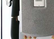
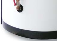
7 MOUNTING INSTRUCTIONS WARNING! At least 20 C and 4 persons are necessary to mount the insulation. All threaded connections shall be sealed either with a thread sealant or with the gaskets included in separate kits. 1. Remove the tank from its pallet and place it to its approximate position, shift the bottom insulation under the tank. 2. Slide the insulation inserts into the openings for connections. 3. Fit on the front insulation part, then the rear insulation part. Check the proper position of the insulation towards the sockets prior to final fixing. Use the jig to close the locks. 7

. 5.")

. 7.")
8 4. Peel off the protective foil from the insulation, apply the self-adhesive annuluses around the openings for connections. Some annuluses are cut out, these shall be used in places where openings are close to each other (the annuluses overlap). 5. Fit the assembly with elbow ball valve (code 12690). From this point on, it is important to stick to the sequence of installation steps described below! 6. Fit the assembly with ball valve and pressure gauge (code 12689). 7. Do hrdla 1 pod skupinu s manometrem namontovat zátku (kód 7691). 8

 - both these")

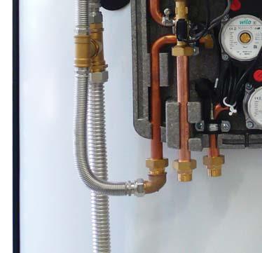
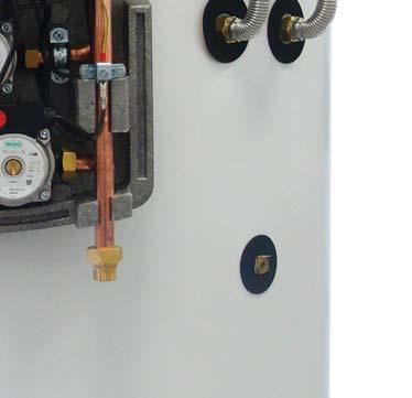
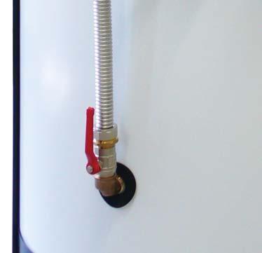
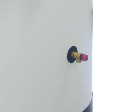
9 8. Fit the 3/4 ball valve (code 998) to the tank and the 3/4 FF hex nipple (code 6970) into the valve, both these components are included in the Kit code Turn the ball valve into the position shown in the fig. 9. Fit the ball valve and elbow assembly (code 13236) into the lower 1 opening. 10. Align the metal sheet against the four pins and fix it using 4 screws M6x16 with washers (codes and 7853) - both these components are included in the Kit code Do not forget to place insulation washers under the metal sheet and loosen the clamps. Fit the pump station with 4-way mixing valves (code or 12225). Using a 5/4 union nut, connect it with the angled valve assembly mounted earlier (see point 5). Tighten the clamps. 9
 - all")

 - included in Kit 13234 with 3/4 ball")
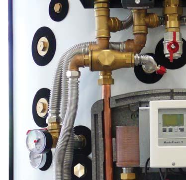
10 11. Fit the fresh water station (code either 9717 or 9913) using 4 screws M6x16 with washers (codes and 7853) - all these components are included in the Kit code Connect the TSV3B assembly (code 12687) using a 3/4 pipe, 100 mm long (code 11946) - included in Kit with 3/4 ball valve - see point Connect the TSV3B assembly with the DHW assembly.. 10
. Prior to fitting, cut the insulation to length and slide it onto the pipe. Fit the solar sheath. SHEATH 16.")
 to 250 mm, insulation to some 300 mm one 3/4 pipe (code 3041) to 450 mm, insulation to some 550mm one 3/4 pipe (code 3041) to 320 mm, insulation to some 400 mm one 5/4 DN25")
11 14. Fit the solar pump station (code 14866) using 2 screws M6x16 and washers (codes and 7853) - all these components are included in the Kit code Connect the solar pump station to the tank using the respective Kit (code 12227). Prior to fitting, cut the insulation to length and slide it onto the pipe. Fit the solar sheath. SHEATH 16. Stretch the pipes to the below listed preliminary lengths, cut the insulation and slide it onto the pipes (included in the Kit code 12226): one 1 pipe (code 11271) to 410 mm, insulation to some 500 mm one 1 pipe (code 3016) to 250 mm, insulation to some 300 mm one 3/4 pipe (code 3041) to 450 mm, insulation to some 550mm one 3/4 pipe (code 3041) to 320 mm, insulation to some 400 mm one 5/4 DN25 pipe (code 13484) to 580 mm, insulation to some 700 mm 11

, connect the zone valve")
 to the T-piece")
12 17. Using the 1 pipe 250 mm long (code 3016), connect the pressure gauge assy with the inner 1 elbow of the pump station with 4-way valves. 18. Fit the 1 pipe 410 mm long (code 11271), connect the zone valve assy with onto the pump station. 19. Fit the 3/4 pipes 320 and 450 mm long (code 3041) to the T-piece assy (code 13983). The 450 mm long pipe shall be fitted at the right-hand side, see fig. 12

, included in Kit 13237,")

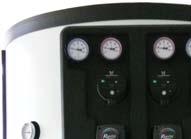
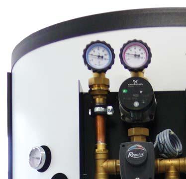
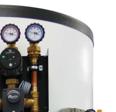
13 20.Connect the T-piece assy at 3 points, see fig. 21. Using the 5/4 pipe 580 mm long, connect the T-piece assy with the ball valve assy. 22. Fit two thermometers (code 10474), included in Kit 13237, and 6/4 and 1/2 plugs or electric heating elements and a safety thermostat. PLUGS 1/2 or SAFETY THERMOSTAT THERMOMETERS PLUGS 6/4 or HEATING ELEMENT 13


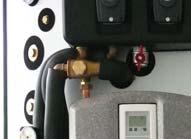
14 23. Fit the hex nipple 6971 into the sleeve and then the safety valve (code 605) included in Kit Push the front insulation onto the pump station with 4-way valves. 25. Connect the terminals of the pumps with cables, push the cables behind the insulation. 14


 and hex nipple (code 6971), all")
15 26. Fit the plastic cover onto the pump station with 4-way valves and fix it with 4 plastic screws M6x10 (code 12713). 27. Fit the top insulation and the top plastic cover onto the tank. 28. Fit the automatic air release valve (code 11708) with ball valve (code 11965) and hex nipple (code 6971), all included in Kit

16 Completely fitted tank: 16


17 5.2 Connecting heating circuits Return line from Heating Circuit 1 G1 F 2. Flow to Heating Circuit 1 G1 F 3. Flow to Heating Circuit 2 G1 F 4. Return line from Heating Circuit 2 G1 F As a variant, LYRA can be supplied with a pump station for one heating circuit only. 5.3 Connecting DHW circuit 1. Hot water outlet G3/4 M 2. Hot water recirculation G3/4 M 3. Cold water inlet G3/4 M As a variant, LYRA can be supplied with a fresh water station without recirculation pump and recirculation line connection. As a variant, a kit with a zone valve can be supplied to ensure controlled thermal layering Connecting solar circuit Inlet from solar collectors G3/4 M 2. Return line to solar collectors G3/4 M 17
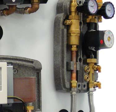
18 5.5 Examples of heat sources connection Inlets and outlets for connecting various heat sources are located across from pump stations for heating and DHW. Openings for electric heating elements are situated left from the pump station for heating. EXAMPLE I: Hydronic fireplace insert with heat exchanger and hydronic boiler (electric, gas, oil or wood pellet fired) electricity gas fuel oil wood pellets boiler hydronic fireplace insert with heat exchanger Kit for expansion vessel connection (code 13437). During operation, the 6/4 valve shall be secured in an open position. EXAMPLE II. Hydronic fireplace insert with heat exchanger, heat pump with flow temperature up to 55 C, electric heating elements. safety temp. limiter el. heating elements hydronic fireplace insert with heat exchanger heat pump max. flow temp. 55 C 18 Kit for expansion vessel connection (code 13437). During operation, the 6/4 valve shall be secured in an open position.
19 EXAMPLE III. Heat pump with flow temperature over 60 C, electric heating elements safety temp. limiter el. heating elements heat pump max. flow temp. 65 C Kit for expansion vessel connection (code 13437). During operation, the 6/4 valve shall be secured in an open position Installation of electric heating elements The Thermal Store can be fitted with up to 2 electric heating elements of max. 12 kw total power output. These elements shall be installed into the G6/4 sleeves in the upper tank section, left from the pump station for heating circuits. The G1/2 port above the el. heating element ports is intended for a safety temperature limiter. All el. heating elements shall be installed together with a safety temperature limiter. Electric heating elements shall be wired by authorized staff only. 19
20 6 - Installation and Commissioning Installation shall meet valid rules and may be done by qualified staff only. Defects caused by improper installation, use or handling are not covered by warranty. After the tank is installed and connected to an existing heating system, it is recommended to clean the entire heating system using a suitable cleaning agent, e.g. MR-501/R. Anti-corrosion protective liquid should be also used, e.g. MR-501/F Commissioning The tank shall be filled up together with the heating system, respecting valid standards and rules. In order to minimize corrosion, special additives for heating systems should be used. The quality of heating water depends on the quality of filling water at commissioning, on the top-up water and on the frequency of topping up. This has a strong influence on the lifetime of heating systems. Poor quality of heating water may cause problems like corrosion or incrustation, esp. on heat transfer surfaces. Fill the heating circuits with the appropriate fluids and air-bleed the entire system. Check all connections for leaks and verify the system pressure. Set the heating controller in compliance with the documentation and manufacturer s recommendations. Check regularly proper function of all control and adjustment elements. 7 - Maintenance If the tank is fitted with a heating element, disconnect it from the mains first. Clean the exterior of the tank with a soft cloth and a mild detergent. Never use abrasive cleaners or solvents Check all connections for leaks. 8 - Disposal Packaging shall be disposed of in compliance with the valid rules. When the product reaches the end of its life, it shall not be disposed of as household waste. It shall be dropped off at a Local Waste Recycling Center. Insulation shall be recycled as plastic and the steel vessel as scrap iron. 9 - Warranty This product is covered by warranty under the conditions listed in this Manual and in compliance with the Warranty Certificate. A Warranty Certificate is an integral part of this accumulation tank scope of supply We reserve the right to errors, changes and improvements without prior notice. v1.6-12/2017 REGULUS spol. s r.o. sales@regulus.eu Web:
CS TSV MIX-REGULUS CS TSV MIX REGULUS. Installation and Operation Manual CS TSV MIX REGULUS PUMP STATION - for boilers and heating systems
 www.regulus.eu CS TSV MIX-REGULUS Installation and Operation Manual CS TSV MIX REGULUS PUMP STATION - for boilers and heating systems EN CS TSV MIX REGULUS CONTENTS: 1 Introduction 3 2 Connection dimensions
STORAGE WATER HEATERS
 Owners Manual STORAG WATR HATRS RBC 200, RBC 300, RBC 400, RBC 500, RBC 500HP, RBC 750, RBC 1000, RBC 1000HP, RBC 1500, RBC 2000, RBC 3000 N v. 1.4 CONTNTS 1 Description... 3 1.1 Models... 3 1.2 Tank protection...
CS TSV MIX REGULUS PUMP STATION - for boilers and heating systems
 Instruction Manual CS TSV MIX REGULUS PUMP STATION - for boilers and heating systems EN v 1.1 CONTENTS: 1 Introduction 3 2 Connection dimensions of CS TSV MIX Regulus 3 3 Function description of CS TSV
Heat Accumulation. thermal stores hot water storage tanks. Energy-saving solutions
 Heat Accumulation thermal stores hot water storage tanks www.regulus.eu HOT WATER STORAGE TANKS WITH NO HEAT EXCHANGER R0BC Hot Water Storage Tanks Hot Water Storage Tanks permitting installation of an
Protection and Control of Solid Fuel Boilers
 Protection and Control of Solid Fuel Boilers thermal relief valves thermostatic valves and pump stations draft regulators www.regulus.eu BOILER PROTECTION AGAINST OVERHEATING Solid fuel boilers may get
INDIRECT WATER HEATERS
 INSTRUCTIONS INDIRECT WATER HEATERS ST-300D, ST-200D HEAT PUMPS STAINLESS STEEL INDIRECT FIRED WATER HEATERS ST-200D, ST-300D 1. Product Description Indirect fired water heaters ST-200D and ST-300D are
TOWEL WARMERS ARE HEAVY! WE RECOMMEND THAT TWO PEOPLE INSTALL THE TOWEL WARMER!
 1. Please follow instructions carefully to ensure that the towel warmer is properly attached to the wall or floor. FAILURE TO FOLLOW THESE STEPS COULD RESULT IN PROBLEMS. 2. Do not use an abrasive or chlorine-based
INSTALLATION AND OPERATING INSTRUCTIONS GN2. HIGH EFFICIENCY CAST IRON BOILER FOR LIQUID and/or GAS FUELS
 INSTALLATION AND OPERATING INSTRUCTIONS HIGH EFFICIENCY CAST IRON BOILER FOR LIQUID and/or GAS FUELS INDEX 1. Technical information... page 3 2. Dimensional and technical characteristics... page 3 3. Packing
Installation and Operation Instructions K36E Modular Heating Circuit - DN 25 Boiler charging set
 PAW GmbH & Co. KG Böcklerstr. 11, D-31789 Hameln, Germany Phone: +49-5151-9856-0, Fax: +49-5151-9856-98 Email: info@paw.eu, Web: www.paw.eu Installation and Operation Instructions K36E Modular Heating
Installation and operating instructions. DK energy storage and DK energy buffer
 Installation and operating instructions DK energy storage and DK energy buffer Edition: 08-2015 1 Preliminary note With this DK energy storage / DK energy buffer you purchased a DK quality product. The
TT /97 WARNING WARNING WARNING INSTALLATION INSTRUCTIONS
 TT-116 2/97 INSTALLATION INSTRUCTIONS Original Issue Date: 2/97 Model: 900/1000 kw Market: Industrial Subject: Block Heater Kits PA-28648, PA-28648-SD The block heater kit heats engine coolant, making
NEPTUNE 1. Model: NEPTUNE Part List English
 Model: -22 Part List English Table of Contents Cabinet 3 Frame 5 Fueltank and detergent tank 7 Motor pump unit 9 El-box 11 Burner unit 13 Distributor, Flow switch 15 Heat exchanger 17 Heat exchanger assy.,
ROTARY VANE VACUUM PUMPS Exploded View DuraVane Rotary Vane Pumps Oil-Lubricated RVL301HH
 Exploded View Pumps RVL0HH 95 SOUTH WOODLAND AVENUE, MICHIGAN CITY, IN 0-57 Please visit our website at Page Number Reference TOLL-FREE: 888-95-5 TEL.: 9-8-0 FAX: 9-8-0 www.dekkervacuum.com DWG //05 RVL0HH
Installation and maintenance instructions
 6304 4995 0/004 GB For installer Installation and maintenance instructions Flue gas heat exchanger WT50/60 Please read thoroughly prior to installation and maintenance. Summary About this manual This equipment
INSTALLATION INSTRUCTION
 INSTALLATION INSTRUCTION Thermostatic Mixer Shower System NOTICE The instruction manual includes part lists, installation instructions, usage of thermostatic and suitable inlet system. Make sure the installation
NOTE: Parts are no longer available for this tool. The manual will continue on the next page.
 NOTE: Parts are no longer available for this tool. The manual will continue on the next page. ------------------------------------------------- CATALOG NO. 7628 Form No. Z21 0 Date 1-93 High Pressure Power
VIESMANN. Installation instructions VITOCELL 300-B. for contractors. Vitocell 300-B Type EVBA-A. Dual mode DHW cylinder, 300 and 500 l
 Installation instructions for contractors VIESMANN Vitocell 300-B Type EVBA-A Dual mode DHW cylinder, 300 and 500 l VITOCELL 300-B 1/2017 Dispose after installation. Safety instructions Please follow these
Heat Exchanger Block Replacement Instructions
 Series 1-4 Gas-fired water boiler Heat Exchanger Block Replacement Instructions Ultra-80 S1-4 Heat Exchanger Block Replacement Kit, Part No. 383-500-773 Ultra-105 S1-4 Heat Exchanger Block Replacement
INSTALLATION, OPERATION AND MAINTENANCE. Ariterm Hybrid 20
 INSTALLATION, OPERATION AND MAINTENANCE Ariterm Hybrid 20 TABLE OF CONTENTS General...3 Installation... 4-5 Dimensions - with flue gas exhauster...6 Dimensions - without flue gas exhauster...7 Pipe installations...8
General System Layout Sketch
 General System Layout Sketch EZ-37 Solar Panels PV panel Glycol Fill Valve Expansion Tank ` 1 Introduction This document describes how to install a Heliatos GH type solar water heating system. These systems
Powerstock Storage Tank
 Powerstock Storage Tank Models ST300, ST500, ST750 & ST1000 INSTALLATION, COMMISSIONING AND SERVICING INSTRUCTIONS THE POWERSTOCK STORAGE TANK IS INTENDED FOR USE AS A COMMERCIAL APPLIANCE. PUBLICATION
Self-Contained Electric Steam Jacketed Kettle
 OWNERS MANUAL Self-Contained Electric Steam Jacketed Kettle Model: FT-20CE COVERING: INSTALLATION OPERATION SERVICE & PARTS An Employee Owned Company 35 Garvey Street l Everett l MA l 02149 Tel: (617)
Installation Manual Universal Side-of-Pole Mount UNI-SP/02A
 Installation Manual Universal Side-of-Pole Mount UNI-SP/02A Solar Mounting Solutions UNI-SP/02A September 2009 www.ironridge.com 2009 IronRidge, Inc. All Rights Reserved Version 2.1 2 Universal Side-of-Pole
Assembly- and Usermanual. Rainmaker. Code No GB. Edition: 09/2007
 Assembly- and Usermanual Rainmaker Code No. 99-97-1729 GB Edition: 09/2007 Table of contents Page I 1 Overview and system specifications.................................. 1 1.1 Purpose of Evaporative
FFP S700 SERIES. Pull-Out Spray Faucet. Installation guide
 FFP S700 SERIES Pull-Out Spray Faucet Installation guide G 1782 G 1748.XX G 29016 G 1156 G R0239.XX G 13396.XX G R0637 G R1664 G 1636 G 1463 TECHNICAL DATA Minimum working pressure 0,5 bar Maximum working
MOUNTING INSTRUCTIONS
 A-12093 JDX 2014 HEATER KIT With Gas Engine Connection Fittings 2014 and Newer ROPS Cabs A-12098 (Kit A-12092, Diesel Engine Connection Fittings are sold separately for diesel models) 12VDC, 2-Speed, 15,000
INSTALLATION INSTRUCTIONS. Cubix Widespread Faucet Part #: 3204, 5204, 3304, 5304 HANDLE STYLES
 INSTALLATION INSTRUCTIONS Cubix Widespread Faucet Part #: 04, 04, 04, 04 Confidence from start to finish. HANDLE STYLES 04 04 jaclo industries Dermody Street Cranford, NJ 001 p 0..44 00..0 f 0..11 00..4..1
VM99 TANK REPLACEMENT PARTS 1. COVER BOLT BOLT (4 REQ'D FOR 21-34), 1/4"-20 x 1" THERMAL CUT-OUT THERMAL TRIP PLUG
, 1/4-20 x 1 THERMAL CUT-OUT THERMAL TRIP PLUG") VM99 TANK REPLACEMENT PARTS 1. COVER BOLT BOLT (4 REQ'D FOR 21-34), 1/4"-20 x 1" 700300-013 2. THERMAL CUT-OUT 409560-001 THERMAL TRIP PLUG 409210-010 3. HEATER TERMINAL COVER VM99 2-4 HEATER TERMINAL
VM99 TANK REPLACEMENT PARTS 1. COVER BOLT BOLT (4 REQ'D FOR 21-34), 1/4"-20 x 1" 700300-013 2. THERMAL CUT-OUT 409560-001 THERMAL TRIP PLUG 409210-010 3. HEATER TERMINAL COVER VM99 2-4 HEATER TERMINAL
Mercury Mixing Kit (Code: ME1053)
") Mercury Mixing Kit (Code: ME1053) The installation and commissioning of the UFH mixing kit system must be exclusively performed by qualified personnel in accordance with the national guidelines and/or
Mercury Mixing Kit (Code: ME1053) The installation and commissioning of the UFH mixing kit system must be exclusively performed by qualified personnel in accordance with the national guidelines and/or
NEPTUNE 2. Model: NEPTUNE 2-13 NEPTUNE 2-20 NEPTUNE 2-25 NEPTUNE 2-26 NEPTUNE 2-30 NEPTUNE 2-33 NEPTUNE 2-38 NEPTUNE Part List US-English
 NEPTUNE 2 Model: NEPTUNE 2-13 NEPTUNE 2-20 NEPTUNE 2-25 NEPTUNE 2-26 NEPTUNE 2-30 NEPTUNE 2-33 NEPTUNE 2-38 NEPTUNE 2-41 Part List US-English Table of Contents NEPTUNE 2 Frame 3 Cabinet 5 Fueltank and
USER MANUAL. PEDESTAL FAN (16 Inch)
") USER MANUAL PEDESTAL FAN (16 Inch) ACFP1016 Hydrofarm.com TABLE OF CONTENTS OVERVIEW 2 PARTS LIST - (WHAT S IN THE BOX) 3 IMPORTANT SAFEGUARDS 4 ASSEMBLY INSTRUCTIONS 4 ASSEMBLY 4 ELECTRIC SCHEMATIC DIAGRAM
USER MANUAL PEDESTAL FAN (16 Inch) ACFP1016 Hydrofarm.com TABLE OF CONTENTS OVERVIEW 2 PARTS LIST - (WHAT S IN THE BOX) 3 IMPORTANT SAFEGUARDS 4 ASSEMBLY INSTRUCTIONS 4 ASSEMBLY 4 ELECTRIC SCHEMATIC DIAGRAM
Global-Tek (Singapore) Pte Ltd
 Pte Ltd") Global-Tek (Singapore) Pte Ltd Door Type G-TEK G-TEK WWW.GLOBAL-TEK.COM.SG 1 P a g e Door Type, CONTENTS Wash and Rinse Arm Assembly....... 3-4 Booster Heater... 5-6 Wash Chamber.. 7-8 Door Lift Assembly...9-10
Global-Tek (Singapore) Pte Ltd Door Type G-TEK G-TEK WWW.GLOBAL-TEK.COM.SG 1 P a g e Door Type, CONTENTS Wash and Rinse Arm Assembly....... 3-4 Booster Heater... 5-6 Wash Chamber.. 7-8 Door Lift Assembly...9-10
Minimalist Bottom Outlet Thermostatic Bar Shower. Telephone Product Specification
 Product Specification ~ Minimum Working Pressure 0.5 bar ~ Maximum Working Pressure 4.0 bar ~ Cold Water Supply Temp 4-20 c ~ Hot Water Supply Temp 55-85 c ~ Fixing Centres 150mm +/- 20mm ~ Outlet size
Technical Data TYPE T14 & T14D TEMPERATURE PILOT SPENCE ENGINEERING COMPANY, INC. 150 COLDENHAM ROAD, WALDEN, NY SD 4511A T14 PILOT
 Technical Data SD 4511A SPENCE ENGINEERING COMPANY, INC. 150 COLDENHAM ROAD, WALDEN, NY 12586-2035 TYPE T14 & T14D TEMPERATURE PILOT PRINTED IN U.S.A. SD 4511A/9811 5 13 /16 D 4 7 /8 1 13 /16 T14 PILOT
TERMO Combi Cylinder TECHNICAL INFORMATION
 TECHNICAL INFORMATION TERMO Combi Cylinder Tank-In-Tank System using solar energy for hot water and heating support. For integration into the heating circuit as return flow booster or hydraulic compensator.
INSTALLATION AND OPERATING INSTRUCTIONS. Ariterm 60+
 INSTALLATION AND OPERATING INSTRUCTIONS Ariterm 60+ CONTENTS General.... 2 Installation.... 4-5 Installation of temperature limit valve... 6 Measurements and connections... 7 Technical specifications and
CR A-F-A-E-HQQE 3x400/ HZ
 GRUNDFOS DATA BOOKLET CR32--2 A-F-A-E-HQQE 3x/69 5 HZ Grundfos pump 9612212 Thank you for your interest in our products. Please contact us for more information, or visit our website https://www.lenntech.com/grundfos/crfam/9612212/cr-32--2-a-f-a-e-hqqe.html
CALEFFI. Anti-condensation circulation unit. 282 series 01225/14 GB. replaces dp 01225/11. Code completion Setting 45 C 55 C 60 C 70 C.
 Anti-condensation circulation unit 8 series ACCREDITED ISO 9 F 654 ISO 9 No. CALEFFI 5/4 GB replaces dp 5/ Function The anti-condensation circulation unit performs the function of connecting the solid
Platen Heater Pad Replacement
 Instruction Sheet P/N Platen Heater Pad Replacement WARNING: Allow only qualified personnel to perform the following tasks. Observe and follow the safety instructions in this document and all other related
Instructions for installation and use Akva Lux II VX substations 1. Contents
 Akva Lux II VX thermostatic control Akva Lux II VX thermostatic control, and optional junction box + zone valve Akva Lux II VX (ECL 110) Akva Lux II VX HWP (ECL210) Akva Lux II VX H2WP (ECL 210) 1. Contents
Akva Vita TDP-F District heating flat station for direct heating and domestic hot water systems
 Akva Vita TDP-F District heating flat station for direct heating and domestic hot water systems Akva Vita TDP-F Table of contents Akva Vita TDP-F...1 Table of contents...1 Safety notes...2 Delivery...2
Parts Manual. Spray Unit Easy Spray-H. Issue /07/17 Ref. NR ENG
 Parts Manual Spray Unit Easy Spray-H Issue 2.5 27/07/17 Ref. NR-00087-ENG Before installing the unit and starting it up, please take the time to read all the technical and safety instructions in the Service
ASSEMBLY and INSTALLATION INSTRUCTIONS. Pipe wrench Ratchet 3/8 socket 9/16 socket 11/16 socket 3/16 Allen key 3/32 Allen key 9/64 Allen key
 ASSEMBLY and INSTALLATION INSTRUCTIONS Gas Conversion Kit Tube Heaters View these instructions online at www.lbwhite.com Kit Contents: DESCRIPTION QTY. Instructions 1 Burner orifi ce 1 Manifold pipe 1
Installation and operation instructions Solar stations SolarBloC midi Premium DN 20 SolarBloC maxi Premium DN 25
 PAW GmbH & Co. KG Böcklerstr. 11, D-31789 Hameln, Germany Phone: +49-5151-9856-0, Fax: +49-5151-9856-98 E-mail: info@paw.eu, Web: www.paw.eu Installation and operation instructions Solar stations SolarBloC
Installation Manual Universal Side-of-Pole Mount UNI-SP/01A
 Installation Manual Universal Side-of-Pole Mount UNI-SP/01A YOUR IRONRIDGE DISTRIBUTOR SOLIGENT 800-967-6917 www.soligent.net Solar Mounting Solutions UNI-SP/01A April 2008 www.ironridge.com 2008 IronRidge,
Dynalux. Floor Heating Manifolds Underfl oor heating circuit manifold
 Dynalux Floor Heating Manifolds Underfl oor heating circuit manifold IMI HEIMEIER / Floor Heating Control / Dynalux Dynalux Dynalux adjusts the flow rate in the individual heating circuits directly in
SBB 300, 400 S & Sbb 300, 400, 600 Plus
 english Operating and Installation Instructions SINGLE AND DUAL HEAT EXCHANGER SOLAR STORAGE TANKS SBB 300, 400 S & Sbb 300, 400, 600 Plus WWW.STIEBEL-ELTRON-USA.COM SBB S & SBB PLUS SOLAR STORAGE TANKS
1592P01. for liquids in piping DN max. DC 48 V, 1 A, 20 W
 594 59P0 Flow switch for liquids in piping DN 0 00. QE90 Contact load / switching capacity: Nominal pressure PN5 Manual setting of contact type (NO / NC) Housing IP 65 / safety class II Maintenance free
CIRCO 6 Solar Circulation Unit
 TECHNICAL INFORMATION / INSTALLATION INSTRUCTIONS CIRCO Solar Circulation Unit CIRCO Solar Circulation Unit in combination with the intelligent SUNGO controllers, it is the safe and reliable heart of a
COMPRESSED AIR DRYER. SAFETY... Page 2 MAINTENANCE... Page 5. INSTALLATION... Page 3 PARTS AND KITS... Page 6
 OWNERS MANUAL BOSS COMPRESSED AIR DRYER Distributed by Air & Vacuum Process, Inc. Phone: 281-866-9700 Fax: 281-866-9717 Email: sales@airvacuumprocess.com SAFETY... Page 2 MAINTENANCE... Page 5 INSTALLATION...
DHW Tanks Indirect Tanks for Domestic Hot Water. New! Single coil tanks with electric element
 Indirect Tanks for Domestic Hot Water New! Single coil tanks with electric element DHW Tanks FOR ALL SOLAR, GEOTHERMAL OR HYDRONIC APPLICATIONS LIMITED LIFETIME W A R R A N T Y Heavy Gauge Steel With Porcelain
CR20-07 A-F-A-E-HQQE 3x400/ HZ
 GRUNDFOS DATA BOOKLET CR2-7 A-F-A-E-HQQE 3x4/69 5 HZ Grundfos pump 965513 Thank you for your interest in our products. Please contact us for more information, or visit our website https://www.lenntech.com/grundfos/crfam/965513/cr-2-7-a-f-a-e-hqqe.html
INSTALLATION INSTRUCTIONS. Uptown Contempo Widespread Faucets Part # s: 8880-****, 8881-****
 INSTALLATION INSTRUCTIONS Uptown Contempo Widespread Faucets Part # s: 0-****, -**** Confidence from start to finish. 0 Handle Options Handle Options L T T T SQL TSQ TSQ TSQ C T0 T T SQC TSQ0 TSQ TSQ jaclo
BASIN MIXERS INSTALLATION & AFTERCARE INSTRUCTIONS
 BASIN MIXERS INSTALLATION & AFTERCARE INSTRUCTIONS This guide covers the installation of all Tavistock basin mixer varients. Please select the installation diagram suited to the basin mixer you have purchased.
Condair Esco. Steam humidification system INSTALLATION INSTRUCTIONS EN 1310
 Condair Esco Steam humidification system L INSTALLATION INSTRUCTIONS 1117775 EN 1310 3 Contents 1 Introduction 4 1.1 General 4 1.2 Safety 4 2 Esco DL40 5 2.1 Overview Esco DL40 5 2.2 Mounting the Esco
GUIDO RAYOS X, S.A. MAN-011 Feb. 01 Ed. 2 / Rev. 1 NESTORET 5050
 42 43 1 2452 HUMIDITY TEMPERATURE SENSORS 2 2213 HOLE DOOR 3 2263 GASKET 4 1273 SCREW DIN 965 M4x10 5 1236 SPRING 6 1309 SCREW DIN 912 M5x45 7 1340 LOCK NUT DIN 985 M5 8 2212 FLANGE 9 2269 LEFT SHAFT 10
Model AV Alarm Valve With and Without Model RC-1 Retard Chamber European Conformity Valve Trim General Description
 Worldwide Contacts www.tyco-fire.com Model AV--00 Alarm Valve With and Without Model RC- Retard Chamber European Conformity Valve Trim General Description The TYCO Model AV--00 Alarm Valves DN, DN0, DN0,
J120 STEAM BOOSTER INSTALLATION, OPERATION, AND SERVICE MANUAL J120 STEAM BOOSTER. J120 Steam Booster Manual D
 INSTALLATION, OPERATION, AND SERVICE MANUAL J120 STEAM BOOSTER J120 STEAM BOOSTER J120 Steam Booster Manual REVISION HISTORY Revision Letter Revision Date Made by Applicable ECNs Details A 10-27-04 CBW
Crown Boiler Company
 Crown Boiler Company 1 Phantom Boiler System Combi Kit Instruction Manual I Product Description This kit adds the ability to generate DHW, as well as heat, ( combi capability) to select Phantom models
VIESMANN. Installation instructions VITOCELL 300-V/W. for contractors. Vitocell 300-V/W Type EVIA-A
 Installation instructions for contractors VIESMNN Vitocell 300-V/W Type EVI- DHW cylinder with internal indirect coil 160 to 500 l VITOCELL 300-V/W 3/2017 Dispose after installation. Safety instructions
TITANIA F4 PYTHON EXPLODED VIEW
 400 DETERGENT DRAWER COVER 40 CONTROL PANEL 402 PR. ADJUSTMENT KNOB GR (470+47) 403 PROGRAMME ADJUSTMENT SHAFT 407 BUTTON-LIGHT GUIDE GROUP 405 LIGHT GUIDES 406 BUTTON LIGHT GUIDE BOX 45 BUTTONS 4 PCB
Installation and maintenance instructions
 6304 4994 03/2006 GB For installer Installation and maintenance instructions Flue gas heat exchanger WT30/40 Please read thoroughly prior to installation and maintenance. Contents Contents Contents 2 1
INSTRUCTION MANUAL HAND HELD STEAM CLEANER JQ688A-1
 INSTRUCTION MANUAL HAND HELD STEAM CLEANER JQ688A-1 Read these instructions carefully before using your steam cleaner. Please keep this instruction manual in safe place for future use. 1 Applicable Standards:
FCT-CE SERIES ELECTRIC TILTING KETTLE W/HAND CRANK PARTS AND SERVICE MANUAL
 FCT-CE SERIES ELECTRIC TILTING KETTLE W/HAND CRANK PARTS AND SERVICE MANUAL EFFECTIVE SEPTEMBER 12, 2014 Superseding All Previous Parts Lists. The Company reserves the right to make substitution in the
A HEATER KIT With Diesel Engine Connection Fittings
 A-12142 HEATER KIT With Diesel Engine Connection Fittings Figure 1 (General Layout and Parts I.D.) Page 1 of 6 Read these instructions and identify all components. Please retain these instructions for
User Manual / Care Instructions
 Product Code: MYWEO140 User Manual / Care Instructions PRODUCT #: MYWEO140 ITEM: Classic Wall Mount from Myson BRAND: Myson SOURCE FOR PURCHASE: SpaEquip, Inc. 211 Wappo Ave., Calistoga, CA 94515 p: 707.737.1100
Installation, Operation and Maintenance Guide G3600 Series Thermostatic Mixing Valves
 Note: Please provide valve serial number (stamped on cover of valve) when ordering parts. Tempered Water Outlet Cold Water Thermometer Hot Water Inline Check Redundant Thermostatic Mixing Valve Angle Checkstops
STREBEL S-CB + Cascade Kits
 STREBEL S-CB + Cascade Kits Models + 60 - + 80 - + 100 - + 120 PX 120 - + 10 - + 180 Installation & Operating Manual 2x60 up to 12x180 Please read and understand before commencing installation and leave
Avensys Avensys FIN EST SLO RUS UAE
 34 037 Avensys Avensys GB D...1...5 I...5 N...9 GR...13 TR...17 BG...21 RO...25 GB...2 NL...6 FIN...10 CZ...14 SK...18 EST...22 CN...26 F...3 S...7 PL...11 H...15 SLO...19 LV...23 RUS...27 E...4 DK...8
AirUnit. Installation instructions. mfh systems modern floor heating. Decentralised domestic ventilation
 mfh systems modern floor heating AirUnit Decentralised domestic ventilation Installation instructions List of contents, Installation instructions Page 1. General information... 03 2. Function / planning
MAKING MODERN LIVING POSSIBLE. Akva Lux II TDP-F. Instructions for installation and use. Danfoss District Energy
 MAKING MODERN LIVING POSSIBLE Instructions for installation and use Danfoss District Energy substations Type 004U8264 Type 0048089 Cover for wall-mounting Type 0048044 Cover for recess mounting 1.0 Contents
DAIRY SECTION STAINLESS STEEL DAIRY FITTINGS COMPLIES WITH 3A SANTARY GUIDELINES
 304 STAINLESS STEEL FITTINGS COMPLIES WITH 3A SANTARY GUIDELINES TRI-CLOVER FERRULE HALF FERHALF32 32mm 1-1/4 FERHALF38 38mm 1-1/2 FERHALF50 50mm 2 FERHALF63 63mm 2-1/2 FERHALF76 76mm 3 FERHALF101 101mm
Installation Manual Universal Single-Arm Side-of-Pole Mount UNI-SA/21.5
 Installation Manual Universal Single-Arm Side-of-Pole Mount UNI-SA/21.5 Solar Mounting Solutions UNI-SA/21.5 March 2009 www.ironridge.com 2009 IronRidge, Inc. All Rights Reserved Version 2.0 2 Universal
SPEAKMAN SAFETY PRODUCTS Installation, Maintenance & Operation Instructions SEF-18XY, EYESAVER FAUCET with SENSORFLOW, Battery or AC POWER
 SPEAKMAN SAFETY PRODUCTS Installation, Maintenance & Operation Instructions SEF-18XY, EYESAVER FAUCET with SENSORFLOW, Battery or AC POWER DESCRIPTION The SEF-18XY, Eyesaver faucet series combines a Gooseneck
Where the tap has a removable aerator on the spout exit it can be removed and cleaned periodically to maintain optimum flow performance.
 TAP6000 3 in Hot Tap Guarantee (UK only): 04-7 Your tap has the benefit of a comprehensive manufacturer s guarantee, details of which are shown on your Proof of Purchase Document. Any claim during the
INSTALLATION INSTRUCTIONS John Deere One Series; 1023E, 1025R and 1026R Models A HEATER KIT. Figure 1 (General Layout and Parts I.D.
 A-11978 HEATER KIT Figure 1 (General Layout and Parts I.D.) Read these instructions and identify all components. Please retain these instructions for future reference and parts ordering information. Refer
Group: LGA-LKA Engine: LGA 184 Drawing: A SPARE PARTS TABLE. POS. CODE DESCRIPTION Qty
 001 7625.060 washer diam. 8,4 1 002 1770.039 bolt M 8 X 1,25 X 28 1 003 1213.205 seal ring 1 004 screw M 6 X 30 0 005 9032.056 dipstick 2 006 1200.003 O ring 118 2 007 gear cover 0 008 4601.047 gasket
INSTALLATION AND OPERATING INSTRUCTIONS
 INSTALLATION AND OPERATING INSTRUCTIONS CONTENTS 2 6 7 8 9 10-12 16 17 18 18 19 2 GENERAL TRANSPORTATION, STORAGE AND OPENING THE PACKAGE Receiving the goods - Storage Opening the package 3 INSTALLATION
EK-Vector RTX 2080 / 2080 Ti
 EK-Vector RTX 2080 / 2080 Ti GPU WATER BLOCK INSTALLATION MANUAL This product is intended for installation only by expert users. Please consult with a qualified technician for installation. Improper installation
Installation S
 Installation S59-2025 Thermostatic Mixing Valve (TMV25) with Optional Cabinet S59-2025RE (with Recess-Mounted Enamel Cabinet) S59-2025RS (with Recess-Mounted Stainless Steel Cabinet) S59-2025SE (with Surface-Mounted
A B A B4
 TM TM SERVICE INSTRUCTIONS Thermo-Aire Heater Kits and Air-Heater Assemblies 383808-A4 383808-B4 383880-A4 383880-B4 DESCRIPTION The Thermo-Aire Heater is used in situations where oils of heavier viscosity
Safety vacuum drying oven for flammable solvents
 VDL series 53 Vacuum drying ovens Safety vacuum drying oven for flammable solvents A BINDER safety vacuum drying oven of the VDL series ensures maximum safety when drying organic solvents standard with
Hakki Pilke Raven spare parts manual
 1 ENGLISH Hakki Pilke Raven spare parts manual Valimotie 1, FI-85800 Haapajärvi, FINLAND Tel. +358 8 772 7300, Fax +358 8 772 732 info@maaselankone.fi, www.maaselankone.fi 2 Table of contents 1 Upper section
Installation Instructions
 Installation Instructions KFN 9855 ide en - CA Installation, repair and maintenance work should be performed by a Miele authorized service technician in accordance with national and local safety regulations
TECHNICAL INSTRUCTIONS
 TECHNICAL INSTRUCTIONS Benchmark 3.0LN 24-Month Maintenance Kit# 58015-04 This kit applies to units with an Ignitor and a separate gas injector. For units with an Ignitor-Injector (P/N 58023), see Kit
GALATEA DOMUS. Dal 1901 COD
 GALATEA DOMUS COD. 9942031.07 REV.00 TABLE 1 Mod. S 1 5163184CM RH CUP-HEATER PIPE 2 5074616LW CUPS-HEATER GRID 3 7819912 SCREW M4X6 4 7474217 ADHESIVE FEET 12,7 H5,8 5 5961602.01 CUPS-HEATER 6 7816002
HERZ Differential Pressure Control Valve 4002
 HERZ Differential Pressure Control Valve 4002 Data sheet 4002, Issue 0118 Dimensions in mm B1 B2 1 4002 41 1 4002 61 1 4002 71 1 4002 42 1 4002 62 1 4002 72 1 4002 43 1 4002 63 1 4002 73 1 4002 44 1 4002
OWNER S MANUAL #DC2000Y #DC2000YCF 2 HP, 1500 CFM DUST COLLECTOR. VERSION 1 -w/ 6 INLET PORT. Model #DC2000Y Global Rd.
 OWNER S MANUAL #DC2000Y #DC2000YCF 2 HP, 00 CFM DUST COLLECTOR VERSION 1 -w/ 6 INLET PORT Model: #DC2000YCF 9900 Global Rd. Philadelphia, PA 191 Model #DC2000Y Thank you for purchasing one of PSI s growing
Systems for central heating
 www.far.eu Highlight Systems and Components for central heating Components for renewable energy systems Pressfar Fittings Presetting valves and thermostatic head Balancing devices Zone valves Metering
Corrugated Coated Stainless Steel Hoses for gas use with European Standard EN 15266:2007
 Easy Economic Quick Corrugated Coated Stainless Steel Hoses for gas use with European Standard EN 15266:2007 Scan this QR Code AT&T by your smartphone! To learn how it works: ayvaz.com/qrcode A MEMBER
INSTRUCTIONS MODEL: MWBT
 Page 1 of 15 INSTRUCTIONS MODEL: MWBT SAFETY INSTRUCTIONS INSTALLATION INSTRUCTIONS OPERATION INSTRUCTIONS MAINTENANCE INSTRUCTIONS WIRING DIAGRAM EXPLODED VIEW / PARTS LIST WARRANTY INFORMATION DISPOSAL
SPARE PARTS EXPLODED VIEW GAS WALL BOILERS Model GENUS HP. Domestic Gas Boilers GENUS HP. R EN - Edition 05-12/10/2011
 SPARE PARTS EXPLODED VIEW GAS WALL BOILERS Model R8216248-05EN - Edition 05-12/10/2011 Domestic Gas Boilers 3580762 45KW IT/ES 08/08... 3580763 GENUS PREMIUM HP 45KW RO/HU/PL 11/08... 3580764 45KW TU 11/08...
Pole Mounting System Installation & Certification Manual
 Pole Mounting System Installation & Certification Manual IronRidge Pole Mount Installation Guide... 2 IronRidge Certification Letter... 11 IronRidge Wet Stamped Drawing... 12 www.ironridge.com 800-227-9523
Fresh Water Station FWS 20 / FWS 30. Manual. Masterpieces. Art.-Nr.: (V1.0) of Solar Technology
 of Solar Technology") Fresh Water Station FWS 20 / FWS 30 Manual Masterpieces of Solar Technology Art.-Nr.: 700096 (V1.0) Table of content 1 Preface 3 1.1 Usage 3 1.1.1 Usage example Fresh Water Station 4 1.1.2 Usage example
Fresh Water Station FWS 20 / FWS 30 Manual Masterpieces of Solar Technology Art.-Nr.: 700096 (V1.0) Table of content 1 Preface 3 1.1 Usage 3 1.1.1 Usage example Fresh Water Station 4 1.1.2 Usage example
sustainable energy solutions
 EN sustainable energy solutions 2 Index Page 3 Index Page 4 Why accumulator tank? Page 5 Why Laddotank? Page 6-7 Buffer tank, PUFFER (500-2 000) Page 8-9 Buffer tank, PUFFER COMPACT (2 500-8 000) Page
INSTRUCTIONS REHAU PRO-BALANCE MIXING MODULE
 INSTRUCTIONS REHAU PRO-BALANCE MIXING MODULE SPECIFICATIONS... 1 OVERVIEW... 2 PRECAUTIONS... 2 MOUNTING LOCATION... 2 CONNECTION TO BOILER PRIMARY PIPING:... 3 ELECTRICAL CONNECTION... 4 FLUSHING THE
MODEL CMA-180UC PARTS MANUAL Rev 1.16
 MODEL CMA-180UC PARTS MANUAL Rev 1.16 CMA DISHMACHINES 12700 KNOTT STREET GARDEN GROVE, CALIFORNIA 92841 800-854-6417 FAX 714-895-2141 wwwcmadishmachines.com TABLE OF CONTENTS MODEL CMA-180UC 1. PARTS
SAN JUAN FRESH WATER COOLING SYSTEMS
 SAN JUAN FRESH WATER COOLING SYSTEMS 4.3-5.7 GI VOLVO Block Only Cooling, Mounted Off Engine Kit #V-111 Installation Instructions San Juan Engineering Heat Exchangers provide thermostatically controlled
INSTALLATION OF VENTING SYSTEM COMPONENTS WARNING
 INSTALLATION OF VENTING SYSTEM COMPONENTS WARNING When installing the EVERHOT IGI model series direct vent water heaters, use only EVERHOT vent/air intake system kits and components. Installation and service
FL PYTHON EXPLODED VIEW
 NO PART NAME QUANTITY 00 DETERJAN DRAWER COVER 0 CONTROL PANEL 02 PR.ADJ.KN GR 03 PROGRAMME ADJUSTMENT SHAFT 0 PROGRAM SELECTION KNOB INSERT PCB BOX 2 ELECTRONIC CARD GR. 9 LCD CARD GR 20 LCD CARD 22 FL