PowerVent. Installation manual (GB) English. Store this document in a safe place UK
|
|
|
- Mildred Atkins
- 5 years ago
- Views:
Transcription

1 PowerVent Installation manual (GB) Store this document in a safe place UK GB
2 Contents page Foreword 3 1. Introduction 3 2. CE declaration 4 3. SAFETY General Regulations Precautions / safety instructions during installation 4 4. Instructions 5 5. Principle of the ignition cycle 5 6. Removing the packaging 5 7. Installation Regulations Electric connection Placing the PowerVent system Flue gas / combustion air system Pressure gauge pipes Control system 9 8. Adjusting the appliance Points of departure Explanation of the table Type of appliance Differential pressure Minimum length Maximum length Length of condense trap hour check Maintenance Parts Malfunctions 13 Appendix 1 Parts included with the delivery 14 Appendix 2 Technical specifications 15 Appendix 3 Figures 16 GB 2
3 Foreword As a manufacturer of gas-fired heating appliances, DRU is developing and producing products in accordance with the highest possible quality, performance and safety requirements. This guarantees that the user will be able to enjoy using his product for many years to come. This PowerVent system has a CE marking, which means that it complies with the essential requirements of the European gas appliance directive. As an installer, you must be competent in the field of atmospheric gas-fired heating and electricity. The installation manual will provide you with the information you need to install the PowerVent system in such a way that the appliance to be placed will operate properly and safely in combination with this system. This installation manual will replace the section flue gas discharge / combustion air supply system in the installation manual for the appliance. This manual will discuss the installation of the PowerVent system and the accompanying regulations. In addition, you will find information on maintenance, as well as possible malfunctions and their possible causes. Appendix 2 contains the technical specifications that are needed for connecting the PowerVent system. The figures are included at the back of this manual (Appendix 3). Carefully read this installation manual and use it in combination with the installation manual of the appliance to be placed.!tip! The following symbols are used in the manual to indicate important information: Work to be performed Suggestions and recommendations You will need these instructions to prevent problems that might occur during installation and/or use. You need these instructions to prevent fire, personal injury or other serious damages. After delivery, you should give this installation manual to the user. 1. Introduction The PowerVent system is a combined, concentric flue gas discharge / combustion air supply system with a forced discharge of the flue gases. It is an additional, independent system that can be connected to various DRU atmospheric gas-fired heating appliances. The forced discharge of flue gases is realized by means of a fan connected to the outlet of the flue gas discharge. By using a ventilator, the flue gases can be discharged over a longer distance than was previously possible for DRU appliances. In order to prevent the fan from malfunctioning, a minimum length is required for the PowerVent system. The maximum length depends on the number of bends in the system. In Appendix 2 Technical specifications you will find the requirements for minimum and maximum length. The passage to the outside can be made by means of a wall terminal or a roof terminal. The roof terminal can end in a sloping or a flat roof. In case of a roof terminal, the fan unit can be placed on the inside or outside of the roof. The advantage of a fan unit on the inside of the roof, is that it will be easier to reach. If it is placed on the outside of the roof, you will need an addition to the fan unit, the rooftop unit. DRU has a number of rooftop units in its range. You will select whether the fan unit is placed on the inside or outside of the roof, when you purchase the PowerVent system. The diameter of the concentric PowerVent system is 60/100 mm. This system is connected by means of an adapter to the flue spigot of the appliance. DRU has a number of concentric adapters in its range. When installing the concentric system in rooms prone to moisture, you must use a coated air supply pipe. It can be supplied through your dealer 3 GB
4 2. CE declaration We hereby declare that the design and construction of DRU s flue gas discharge / combustion air supply system comply with the essential requirements of the Gas Appliance Directive. Product: flue gas discharge / combustion air supply system type: PowerVent Applicable EEC directives: 2009/142/EC 2006/95/EC 2004/108/EC Applied harmonized standards: NEN-EN-613 NEN-EN-613/A1 NEN-EN-613/A2 NEN-EN NEN-EN Internal measures by the company guarantee that flue gas discharge / combustion air supply systems produced in series comply with the essential requirements of the prevailing EEC directives and the standards derived from them. This declaration will lose its validity if adjustments are made to the appliance, without prior written permission by DRU. M.J.M. Gelten General Director DRU Verwarming B.V. PO Box 1021, 6920 BA Duiven Ratio 8, 6921 RW Duiven 3. SAFETY 3.1 General - Carefully read this chapter on safety, before you start performing installation or maintenance work; - Please observe the general regulations and the precautions/safety instructions in this manual. 3.2 Regulations Please install the PowerVent system, including the electrical installation, in accordance with the applicable national, local and constructional (installation) regulations. In the Netherlands, the Buildings Decree (Bouwbesluit) applies. 3.3 Precautions / safety instructions during installation Carefully observe the following precautions/safety regulations: you should only install and maintain the PowerVent system if you are a competent installer in the field of gas-fired heating and electricity; Install the bracket with PowerVent control components directly on the bracket with the control components for the appliance in the control hatch, as explained in the manual. The control hatch is obligatory when installing PowerVent and is available via the manufacturer. do not make any changes to the system; take the minimum length of the PowerVent system into account; place the adapter directly on the appliance s flue spigot; place the measuring unit (venturi) preferably vertical, within 1 metre of the flue spigot; connect the pressure gauge pipes leak-tight, before the chimney breast is placed; make sure the pressure gauge pipes are free from parts that will become hot; avoid dirt, including metal particles in pipes and connections; avoid kinks in the pipes; place electric wiring in such a way that it is free from the appliance; for connecting the ventilator, you must use a control cable that complies with the applicable standard; when performing work at the installation, you must disconnect it from the power supply by removing the 230V plug from the socket; replace damaged mains sockets in order to avoid dangerous situations; use a coated air supply pipe when installing in rooms prone to moisture. GB 4
5 4. Instructions Dru uses two control systems, Mertik (RCE) and Honeywell (RCH). In case of a Mertik system, please check whether the code number on the receiver ends with AUT (see fig. 8a). If this is not the case, please contact DRU Service; Reserve space in the chimney breast for placing the control hatch with the PowerVent control unit; place a 230V connection with earthing near the appliance, as close as possible to the control hatch; test the complete system for a correct operation, before closing the chimney breast. 5. Principle of the ignition cycle Below you will find a brief description of how an appliance, that is connected to the PowerVent system, is ignited; see fig. 1. The Mertik system uses a pilot flame to ignite the appliance. Appliances with Honeywell control ignite directly on the burner. In both cases, the appliance is switched on with a remote control (A). Via the remote control, the receiver (B) will get the signal to start the ignition process. At the same time, the control unit (D) of the PowerVent system will get a start signal from the receiver. In case of the Mertik system, the pilot flame is ignited at that moment and the fan (E) is switched on. In the case of Honeywell, the fan will switch on and ignition starts after 8 seconds. After ignition, the operation of both systems is identical. It will be determined whether sufficient flow is available in the discharge system. For this purpose, the pressure sensor (H) measures the differential pressure over the measuring unit (venturi, F). If the differential pressure exceeds the value set on the control unit (D), the safety valve (I) will be opened and the gas to the main burner of the appliance is released. If the differential pressure is below the set value, the main burner of the appliance will not ignite In the malfunction table in Chapter 10 you will find possible causes and solutions. 6. Removing the packaging Note the following items when removing the packaging of the PowerVent system: Check the system for damages during transport. If necessary, contact DRU Service. Check whether all parts have been supplied. In Appendix 1 / Table 2 you can see which parts you should have after removing the packaging. Contact DRU Service if you do not have all the parts after you finished removing the packaging. Dispose of packaging in accordance with local regulations. 7. Installation Read this manual carefully to ensure a proper and safe operation of the appliance connected to the PowerVent system.! Install the PowerVent system in the order described in this chapter. 7.1 Regulations - observe the applicable national, local and constructional (installation) regulations for the PowerVent system as well as the electric installation. - Observe the regulations/instructions stated in this manual. 7.2 Electric connection At the appliance, a 230V connection with earthing must be placed, as close as possible to the control hatch. - Replace damaged mains sockets in order to avoid dangerous situations. 5 GB
6 7.3 Placing the PowerVent system The PowerVent system allows many different configurations; see fig. 2a to 2c. The system will be installed after the appliance has been placed on its final location. The bracket with the PowerVent control components (control unit, pressure adjustment unit, pressure sensor and safety valve) must be connected to the controller of the appliance (such as the gas control), so that the whole unit can be placed in the control hatch as described in the manual. The pressure gauge pipes can no longer be reached after the chimney breast has been placed. Leaks will affect the gauge signal to the pressure sensor and therefore the combustion process. That is why these pipes must be connected leak-tight, BEFORE the chimney breast is completed. - Make sure the PowerVent control system is properly connected to the control system of the appliance and fits in the control hatch; - Connect the pressure gauge pipes to the measuring unit, before the chimney breast is completed; - Check whether the pressure gauge pipes are connected leak-tight before finishing the chimney breast. For the benefit of the installation, the PowerVent system has been subdivided in a number of parts: - flue gas / combustion air system; see section 7.3.1; - pressure gauge pipes; see section 7.3.2; - control system; see section Flue gas / combustion air system The passage to the outside can be made with a wall terminal, as displayed schematically in fig. 2d (see section ), as well as a roof terminal (see section ). The roof terminal can be placed in a sloping or a flat roof. When a roof terminal is chosen, the fan unit can optionally be placed on the inside of the roof (see schematic display in fig. 2e and fig. 2f) or on the outside (see schematic display in fig. 2g and fig. 2h. For placement of the fan unit on the outside of the roof, you will need an additional rooftop unit. The solution on the inside of the roof can be made with a wall terminal (see fig 2i). Chapter 8 states a few conditions. The appliance must be adjusted in such a way that it will function properly in combination with the PowerVent system; see chapter 8 of this manual, Adjusting the appliance. The diameter of the concentric PowerVent system is 60 / 100 mm. This system is connected by means of an adapter to the flue spigot of the appliance. - For the PowerVent system you should only use the concentric flue gas discharge material supplied by DRU. This system has been tested together with the appliance. DRU cannot guarantee a proper and safe operation of other systems and does not accept any liability for this; - Take the minimum length of the PowerVent system into account; see section and appendix 2 with the technical specifications; - Take the maximum length of the PowerVent system into account; see sections and and appendix 2 with technical specifications; - Place the adapter directly on the appliance s flue spigot; see fig. 1, G; - Place the measuring unit (venturi) preferably vertical, within 1 metre of the flue spigot; see fig. 1, F; - Place the fan unit correctly; - For connecting the ventilator, use a control cable that complies with the applicable standard; - Place the ventilator s control cable in a cable protection sleeve; - Make sure the pressure gauge pipes are free from parts that will become hot; - Maintain a distance of at least 50 mm between the outside of the PowerVent system and the walls and/or the ceiling. If the system is built in (for instance) a cove, it should be made with non combustible and heat-resistant material all around it; - Use a coated air supply pipe when installing in rooms prone to moisture; - Use non combustible and heat-resistant insulation material when passing through combustible material; - The first 5 metres of the air supply / flue gas discharge pipe must be safely separated from combustible material by means of a non combustible plate, if the distance between the pipe and the combustible material is less than 100 mm. If the pipe is surrounded by combustible material, it should be sleeved with non combustible material and the sleeve must be ventilated. - Heat bridges, e.g. by means of mounting brackets, should be avoided. - For larger distances than 5 metres, a 50 mm safety distance from combustible materials should be observed. GB 6
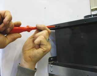
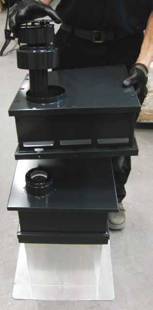
7 ! - Make sure the fan unit can be reached for maintenance; - Make sure the control cable is sufficiently long; - Some heat-resistant insulation materials contain volatile components that will spread an unpleasant smell for a prolonged time; these are not suitable Application with wall terminal The temperature of (the outside of) the concentric system can reach 200 ºC at the wall. Placing the PowerVent system is done as follows: Check whether the concentric system to be applied complies with the minimum and maximum allowed length; see section and and appendix 2 with the technical specifications. Build the system up from the flue spigot of the appliance. Place the adapter directly on the appliance s flue spigot. Place the measuring unit (venturi) preferably on the adapter. Connect the concentric pipe pieces and the bends.! Make sure that the clip binding with silicone sealing ring is mounted correctly, in order to prevent leakage at the connections. On each connection, apply a clip binding with silicone sealing ring. Use a self-tapping screw to fix the clip binding to the pipe on locations that cannot be reached after installation. Apply sufficient clamps, so that the weight of the pipes does not rest on the appliance. Remove the cover of the fan unit. Make a hole in the wall for the concentric system (see fig. 3a for the dimensions and fig. 3b). Make a hole in the wall for the ventilator s control cable protection sleeve (see fig. 3a for the dimensions and fig. 3b). Fix the fan unit to the wall (see fig. 3a for the dimensions and fig. 3c). Cut the pipe piece that is used for connecting to the fan unit to size. Make sure that the right insertion length is maintained. Connect the pipe piece to the fan unit. - Make sure the inlet of the fan unit properly connects to the concentric system; - Make sure that the control cable is connected exactly as indicated in fig. 3d in order to avoid contact between the cable and the hot ventilator. Connect the control cable to the connector (see fig. 3d). Lay the control cable - provided with cable protection sleeve - towards the appliance. Kit the fan unit all around with a suitable kit (see fig. 3e). Place the cover back on the fan unit (see fig. 3f). Place the flue gas discharge pipe (see fig. 3g). Fix the cover with the self-tapping screws supplied (see fig. 3h) Application with roof terminal The roof terminal can end in a sloping or a flat roof. In case of a passage through the roof, the fan unit can be placed on the inside or outside of the roof. If it is placed on the outside of the roof, you will need an addition to the fan unit, the rooftop unit (see the schematic display in fig. 2g and 2h) Placing the fan unit on the inside of the roof Placing the PowerVent system is done as follows: Check whether the concentric system to be applied complies with the minimum and maximum allowed length (see section and and appendix 2 with the technical specifications). Build the system up from the flue spigot of the appliance. Place the adapter directly on the appliance s flue spigot. Place the measuring unit (venturi) preferably on the adapter. Connect the concentric pipe pieces and the bends. Make sure that the clip binding with silicone sealing ring is mounted correctly, in order to prevent leakage at the connections. 7 GB
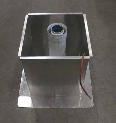
8 On each connection, apply a clip binding with silicone sealing ring. Use a self-tapping screw to fix the clip binding to the pipe on locations that cannot be reached after installation. Apply sufficient clamps, so that the weight of the pipes does not rest on the appliance. Place the strip that is used for connecting the fan unit s clamps (see fig. 4a, 1). Attach the fan unit s clamps to the strip (see fig. 4a, 2). Remove the cover of the fan unit. Place the fan unit on the clamps.!tip The fan unit can be turned and can therefore be placed on the clamps in four ways. Choose the way that is most practical for you.! Secure the fan unit with the self-tapping screws supplied. Connect the control cable to the connector (see fig. 4b). Make sure the control cable is sufficiently long, because of maintenance work. - Make sure that the control cable is connected exactly as indicated in fig. 4b in order to avoid contact between the cable and the hot ventilator; - Make sure the cover is placed correctly on the fan unit, so that the outlet of the fan connects to the outlet of the cover. Lay the control cable - provided with cable protection sleeve - towards the appliance. Place the cover back on the fan unit (see fig. 4c. Secure the cover with the self-tapping screws supplied. Connect the concentric system to the fan unit.!!! Use a telescopic pipe piece for connecting the concentric system. As a result, it will be easier to perform maintenance work. Place the roof terminal on the fan unit. - Make sure that the universal tile fits well with the surrounding tiles; - Make sure that the adhesive plate fits well onto the flat roof Placing the fan unit on the outside of the roof Placing the PowerVent system is done as follows: Check whether the concentric system to be applied complies with the minimum and maximum allowed length (see section and and appendix 2 with the technical specifications). Build the system up from the flue spigot of the appliance. Place the adapter directly on the appliance s flue spigot. Place the measuring unit (venturi) preferably on the adapter. Connect the concentric pipe pieces and the bends. Make sure that the clip binding with silicone sealing ring is mounted correctly, in order to prevent leakage at the connections. On each connection, apply a clip binding with silicone sealing ring. Use a self-tapping screw to fix the clip binding to the pipe on locations that cannot be reached after installation. Apply sufficient clamps, so that the weight of the pipes does not rest on the appliance. Make a hole in the roof for the concentric system. Make a hole in the roof for the ventilator s control cable protection sleeve. Place the rooftop unit on the roof (see fig. 5a for application with a flat roof). Remove the cover of the fan unit. Place the fan unit on the rooftop unit. Cut the pipe piece that is used for connection to the rooftop unit to size. Make sure that the right insertion length is maintained. Connect the pipe piece to the rooftop unit. GB 8
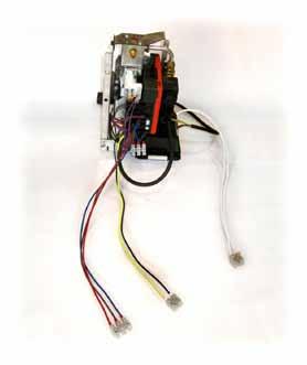
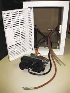
9 - Make sure the inlet of the fan unit properly connects to the concentric system; - Make sure that the control cable is connected exactly as indicated in fig. 4b in order to avoid contact between the cable and the hot ventilator; - Make sure the cover is placed correctly on the fan unit, so that the outlet of the fan connects to the outlet of the cover; - When placing the upper part and the cover, make sure the outlets connect onto each other.! Attach the rooftop unit and the fan unit to each other, using the self-tapping screws supplied. Connect the control cable to the connector (see fig. 4b). Lay the control cable - provided with cable protection sleeve - towards the appliance. Place the cover back on the fan unit (see fig. 5b). Place the upper part and the cover of the version that is placed on the outside of the roof (see fig. 5b). Attach the upper part and the cover to the fan unit, using the self-tapping screws supplied. - Make sure that the universal tile of the rooftop unit fits well with the surrounding tiles; - Make sure that the adhesive plate fits well onto the flat roof Pressure gauge pipes The pressure gauge pipes are attached between the measuring unit (fig. 1, F) and the pressure sensor (fig. 1, H) in order to measure the differential pressure over the measuring unit. The first part of the pressure gauge pipes is made of aluminium. The aluminium pipes must be mounted in such a way that they do not touch the parts that become hot. Moreover, the gauge pipes must be attached without strain. The aluminium gauge pipes run until below the appliance. After that they will change into silicone hoses. Finally, the silicone hoses are connected to the pressure sensor. The pipes must be cut to size on site. Follow the next steps: Connect the brass elbow joints (2 items) to the measuring unit; see fig Tighten the joints until they are leak-tight; after installation you will no longer be able to reach them; - Make sure the pressure gauge pipes are free from parts that will become hot; - Remove any burrs after shortening the pipes; - Avoid dirt, including metal particles in pipes and connections; - Avoid kinks in the pipes; - Make sure that the transition from aluminium pipe to silicone hose can always be reached. Roll out the aluminium pipes towards the appliance. Connect the aluminium pipes to the brass joints; see fig. 6. Attach the aluminium pipes in such a way that there is no strain. Determine the length of the aluminium pipes. Saw the pipes to size. Connect the silicone hose to the aluminium pipes.! The silicone hoses can only be connected to the pressure sensor, after the box with the control system has been placed. The pressure sensor is in the box with the control system Control system The control system consists of components that are needed for the safe operation of the appliance in combination with the PowerVent system. These components (control unit, pressure adjustment unit, pressure sensor and safety valve) are mounted on a bracket that can be connected to the bracket with the Mertik or Honeywell control components, in order to mount them in the obligatory control hatch. This control hatch is available via the manufacturer. Before placing the PowerVent control system plus Mertik or Honeywell controller combination in the control hatch, a number of components must be connected or adjusted, and the PowerVent system should be tested for proper operation. - The PowerVent system is only permitted in combination with an accompanying, lockable control hatch that comes with the appliance, in order to be able to meet the safety requirements. This control hatch is available via the manufacturer; - Take the safety requirements into account when placing the control hatch, as described in the installation manual for the appliance concerned; - Place the safety valve in the correct flow direction in order to prevent leakage of the valve; 9 GB
10 - Connect the correct silicone hose to the correct connection point on the pressure sensor; see fig 6, P1 and P2; - Remove any residual glue after loosening the joint on the gas control, in order to prevent them from entering the gas flow. Place the control system as follows: In case of a Mertik system, connect the PowerVent control components between the gas control and main burner. The bracket with the PowerVent control components will fit on the bracket with the Mertik control components in only one way (see fig. 7a): - On the gas control, loosen the joint of the gas pipe that runs to the main burner; - Remove the joint; - Attach the supplied point piece to the safety valve of the PowerVent control system (see fig. 7a, A and G2); - Connect the gas pipe that runs to the main burner to this (A and G2); - Slide the supplied clamp swivel (B) and clamp bush (C) over the pre-mounted gas pipe; - Place the bracket with the PowerVent control components on the bracket with the Mertik control components, in such a way that the pre-mounted gas pipe with the clamp swivel (B) and clamp bush (C) can be screwed into the exit (G1) of the gas control; - Tighten the gas pipe with clamp swivel (B) and clamp bush (C) in the exit (G1); - Attach the 2 brackets with the 2 self-tapping screws (P);!Tip In case of a Honeywell system, connect the PowerVent control components before the gas control. The bracket with the PowerVent control components will fit on the bracket with the Honeywell control components in only one way (see fig. 7b): - Place the bracket with the PowerVent control components on the bracket with the Honeywell control components, in such a way that the pre-mounted gas pipe with the point piece (B) can be screwed into the entrance (G2) of the gas control; - Tighten the gas pipe with the point piece (B) in the entrance (G2); - Attach the 2 brackets with the 2 self-tapping screws (P); - Attach a point piece (A) to the safety valve (G1); - Connect the gas supply to the point piece (A). Pull the pressure gauge pipes and the ventilator s control cable to the outside through the control hatch. (see fig. 7c); Connect the pressure gauge pipes to the pressure sensor, so that (see fig. 6 and for Mertik fig. 7a or for Honeywell fig. 7b): - the pipe comes as close as possible to the appliance s flue spigot at P1; - the other pipe ends at P2. Connect the fan unit s control cable to the connector (V1) of the control unit (for Mertik: Fig. 7a; for Honeywell: Fig. 7b); If necessary, remove the receiver from the control hatch; Connect the supplied relay cable. Connect the long lead of the relay cable to the connector (V2) in the control system (for Mertik see: Fig. 7a; for Honeywell: Fig. 7b); Connect the short lead of the relay cable (for Mertik: see fig. 8a; for Honeywell: see fig. 8b). Use a 230V connection with adapter as power supply for the receiver, in order to prevent malfunctions as a result of empty batteries in the receiver (Mertik). Insert the 230V plug of the control unit in the socket intended for that purpose. Set the pressure difference on the adjustment unit, before building in the control system. - The differential pressure that has to be set depends on the appliance; - Only set the differential pressure; - The other settings of the adjusting unit must remain unchanged. The differential pressure is adjusted as follows (for the values, see appendix 2 with the technical specifications): Hold down the P key of the adjusting unit for at least 10 sec. (see for Mertik: Fig. 7a; for Honeywell: Fig. 7b, I1 and fig. 9): The display will show the following read-out: 0 00 (flashing) : 01. Then, briefly press the P key: The read-out on the display will change from 01 to 02. Set the correct value, using the + and - keys. GB 10
11 Hold down the P key for at least 5 sec when the correct value has been reached: If the screen returns with the original display, the pressure is adjusted. The PowerVent system is now ready to be tested.!tip Testing should be performed prior to finishing the chimney breast and before mounting the assembly of PowerVent control components and Mertik or Honeywell control components in the control hatch. Check all connections for gas-tightness, before igniting the appliance. Test the PowerVent system for proper operation. If the system operates to your satisfaction, proceed as follows: Isolate the system from its supply voltage; Place the complete assembly of appliance controller and PowerVent controller in the control hatch (see fig. 7a or 7b;!!Tip Make sure that hereafter the control hatch is locked in accordance with the regulations. Reconnect the voltage supply to the system; It is recommended to measure whether the required pressure difference is achieved and only then close the chimney breast or cove around the discharge system. This does not necessarily require a burning appliance, but can also be performed on air. This will prevent the chimney breast from having to be broken up in case of problems. 8. Adjusting the appliance This chapter provides the technical specifications that are required for the PowerVent system to operate properly in combination with the appliance. Appendix 2, table 3 contains the conditions; the conditions depend on the type of appliance. The appliance must be installed without air inlet guide(s) and without the restrictor slide that is supplied with the appliance. 8.1 Points of departure Application of the PowerVent system is allowed up to a certain maximum length. Each bend is calculated as 2 metres. No distinction is made between 45 and 90 bends. For example: According to table 3 in appendix 2, the maximum allowed length in case of the Milo is 36 metres. If three bends are used, a maximum of 30 metres of concentric pipe may be connected. 8.2 Explanation of the table Below, the layout of table 3 in appendix 2 is explained Type of appliance This column lists the appliances that are suitable for connection to PowerVent Differential pressure This column shows the differential pressure, in Pascal, which has to be set on the adjusting unit Minimum length This column indicates the minimum length of the PowerVent system, in metres, that is necessary in order to prevent the fan from becoming defective. The minimum length is the real length in metres of concentric pipe. Here, the bends may NOT be included in the calculation (2 metres are 1 bend). In case of a solution below the roof with wall or roof terminal, a concentric pipe of maximum 1 metre may be placed between the fan unit and the wall or roof terminal. Do NOT include this metre in the calculation when determining the minimum length of the concentric pipe. 11 GB
12 8.2.4 Maximum length This column states the maximum length of the PowerVent system. The maximum length is the real length is metres of pipe. In case of a solution below the roof with wall or roof terminal, a concentric pipe of maximum 1 metre may be placed between the fan unit and the wall or roof terminal. DO include this metre in the calculation when determining the maximum length of the concentric pipe. The bend at the wall terminal (counts for 2 metres) is also included in the calculation. The wall terminal, on the other hand, is NOT included Length of condense trap If flue gases have to be transported over a long distance, they may cool down to below dew point, and condensation may occur. The condensation generated must be discharged via a condense trap. From a certain length, a condense trap will have to be placed. It concerns the real length in metres of pipe. Use a condensation receptacle with stench-trap. If an odour trap is used, it should be filled with water at all times. It may not become dry. A consequence of a dry odour trap could be that the appliance no longer switches on or that the discharge gases flow into the water discharge system. This means that a condense discharge should always be connected to a siphon filled with water. There are other possibilities as well. For instance, it is possible to use a liquid free odour trap. An example of this is the Hepworth HepvO, Hygienic self sealing waste valve.!! - The condensation receptacle may not become dry. - A temperature of the exhaust gases that is too high could damage the condensation receptacle. That is why the condensation receptacle should be placed after a minimum length of the concentric system. Consult table 3. Add 4 metres to the stated minimum length of the concentric system. The result is also the most ideal distance for placing the condensate receptacle. Place the condensate receptacle in a horizontal section of the concentric pipe. Provide a slope from the concentric pipe to the condensate receptacle. In some situations more than one condensate receptacles (see fig.10, C) should be placed. This is the case if the concentric pipe shows a downwards and then upwards slope AFTER the indicated minimum length (see fig. 10, B) and this pattern is repeated. Tip! Advice the user not to let the pilot flame burn, in order to prevent condensation in the appliance. The condensate receptacle is available at your dealer and can be supplied by DRU hour check The PowerVent control system consists of a 24 hour check. This means that every 24 hours the system has been live, it will switch off and switch on again. This has consequences for the appliance. If PowerVent is provided on an appliance with Mertik system, the main burner will momentarily switch off and switch on again, while the pilot flame continues to burn. If it concerns an appliance with Honeywell system, the appliance will enter into malfunction and switch off. In order to prevent this, we recommend the following solutions. Normal atmospheric use: Remove the PowerVent plug from the outlet and insert it again at a time when the appliance is never used (e.g. 7 am). Appliance is used continuously (e.g. in hotel lobby): Use the clock to switch off the appliance at a suitable moment, at the moment of the 24 hour check. In thermostatic mode, the appliance is also used for functional heating: Set the clock in the same way as described above. GB 12
13 9. Maintenance Once a year the system should be checked, cleaned and, if necessary, repaired by a competent installer in the field of atmospheric gas-fired heating and electricity. When performing work at the installation, you must disconnect it from the power supply, by removing the 230V plug from the socket. 9.1 Parts Parts that must be replaced, can be obtained from your supplier. 10. Malfunctions In the following table you will find an overview of malfunctions that might occur, the possible causes and the remedies Table 1: diagnosis of malfunctions Problem Possible cause Remedy A. fan is activated, but appliance does not ignite. code between receiver and 1. the (new) communication remote control must still be confirmed. 2. the odour traps of the condense trap are dry. B. no pilot flame. (Mertik) C. pilot flame ignites, but main burner does not ignite. (Mertik) Does spark, but does not ignite. (Honeywell) D. appliance ignites, but after 30 minutes the flames are still a hazy blue (toxic). E. the appliance always switches off and on at the same time, pilot flame continues to burn (Mertik), or the appliance switches off and enters into malfunction. (Honeywell) 1. See the Installation Manual of the appliance, chapter Malfunctions, in the table under no pilot flame. 1. Fan not connected or blocked. 2. Silicone hoses are not connected leak-tight. 3. maximum length / max. number of bends of the Power- Vent exceeded. 4. Flue gas discharge is not connected leak-tight. 5. pressure gauge hoses have been connected the wrong way around. 1. Confirm the code, as described in the Installation Manual of the appliance, chapter Malfunctions, in the table under solution A1. 2. make sure there is sufficient water in the odour traps or use liquid free odour traps. (see chapter 8.2.5) 1. See the Installation Manual of the appliance, chapter Malfunctions, in the table under no pilot flame. 1. Check whether the fan rotates after the appliance has been ignited. - If necessary, connect the ventilator; - If necessary, repair blockage 2. Check the connections. If necessary, connect the silicone hoses leaktight. 3. Check length and number of bends. If necessary, correct to max. length / max. number of bends. 4. Check connections and silicone rings for leaktightness. If necessary, connect them leak-tight. 5. Properly connect the hoses. 1. Differential pressure incorrect. 1. Set the correct differential pressure; see appendix 2 with the technical specifications for the value. 1. the 24 hour check of the PowerVent is being performed. 1. Set the time of the 24 hour check differently, as described in chapter GB
14 Appendix 1 Parts included with the delivery In the following table you can find the parts that are supplied with the appliance. Table 2: Parts included with the delivery Part Number Installation manual 1x Relay cable (Mertik or Honeywell) 1x Fan unit 1x Aluminium pressure gauge pipe 2x Silicone pressure gauge pipe (hose) 2x Bracket with control system (Mertik (RCE) or Honeywell (RCH)): - Control unit 1x - Adjusting unit 1x - Pressure sensor 1x - Safety valve 1x Straight adapter for safety valve 1x Adapter 1x Clamps Joints Screws GB 14
15 Appendix 2 Technical specifications Type of appliance Table 3: Technical specifications Differential pressure Minimum length Maximum length Length condense trap (Pa) (metre) (metre) Apollo > 18 Apollo > 18 Centro > 12 Excellence L > 17 Excellence M > 17 Excellence XT > 17 Global 60 XT BF > 16 Global 60 Corner BF > 16 Global 60 Triple BF > 16 Global Corner M > 16 Global Triple M > 16 Global 70 BF > 17 (metre) Global 70 XT BF > 18 Global 100 BF > 16 (up to and including 2012) Global 100 BF > 17 (from 2013) Lugo > 16 Lugo > 16 Metro 80 XT (tunnel) > 18 Metro 100 XT (tunnel) > 18 Metro 100 XT > 17 Metro 100 XT > 17 Metro 100 XTL > 18 Metro 130 (tunnel) > 20 Metro 130 XT (tunnel) > 16 Metro 130 XT > 16 Metro 130 XT > 16 Metro 130 XTL > 16 Metro 150 XT (tunnel) > 14 Milo > 18 Milo S > 16 Prestige (tunnel) > 18 Saxo 70 SL > 19 Saxo 80 SL > 20 Scenic 70 SL > 19 Scenic 80 SL > 20 Bends (45º or 90º) are calculated as 2 metres, when determining the maximum length. 15 GB


16 Appendix 3 Figures 230 V F G E 38C H K Mertik Honeywell 230 V B I B A D C C 230 V A I J 1 2a 38c-1552 GB 16
17 38c c b 2c 2d 38C e 17 GB
18 powervent - installation manual 38c C f 2g 38C C h 2i GB 18


19 c p a 3b 38p P c 3d 38p p e 3f 38p p g 3h 19 GB


20 38p a 2 1 4b 1 4c 38p b 5a 6 P1 P2 GB 20

21 A P x2 G2 V1 P2 B C G1 P1 V2 I1 38c-2226 /0 7a 21 GB

22 P x2 P1 P2 A B G1 G2 I1 V1 V2 38C-2227 /0 7b GB 22


23 38p p-00967c 8a L N 38p-0288/1 8b 9 C B C 38c GB
24 powervent - installation manual DRU Verwarming B.V. The Netherlands Postbus 1021, NL-6920 BA Duiven Ratio 8, NL-6921 RW Duiven GB
PowerVent. Installation manual (GB) English. Store this document in a safe place UK
 English. Store this document in a safe place UK") PowerVent Installation manual (GB) Store this document in a safe place 959.034.03.UK GB Contents Blz Foreword 3 1. Introduction 3 2. CE declaration 4 3. SAFETY 4 3.1 General 4 3.2 Regulations 4 3.3 Precautions
PowerVent Installation manual (GB) Store this document in a safe place 959.034.03.UK GB Contents Blz Foreword 3 1. Introduction 3 2. CE declaration 4 3. SAFETY 4 3.1 General 4 3.2 Regulations 4 3.3 Precautions
PowerVent Installation manual. English. Store this document in a safe place EN
 PowerVent - 02 Installation manual Store this document in a safe place 959.114.01.EN en Contents Page Foreword 3 1. Introduction 3 2. CE declaration 4 3. SAFETY 4 3.1 General 4 3.2 Regulations 4 3.3 Precautions
User manual (GB / IE) for appliances provided with an electronic ignition on the remote control. English. Read this document and store it carefully
 for appliances provided with an electronic ignition on the remote control. English. Read this document and store it carefully") User manual (GB / IE) for appliances provided with an electronic ignition on the remote control Read this document and store it carefully 958.007.07.uk 1 UK Contents page Preface 2 1. Introduction 3 2.
User manual (GB / IE) for appliances provided with an electronic ignition on the remote control Read this document and store it carefully 958.007.07.uk 1 UK Contents page Preface 2 1. Introduction 3 2.
Circo RCE G20/G25/G25.3/G31. Installation manual. English. Store this document in a safe place DRU EN-US
 irco RE G20/G25/G25.3/G31 Installation manual Store this document in a safe place 959.044.02.UK DRU-175417-EN-US-1017-4 EN INSTLLTION MNUL ontents 1. Introduction 2. E declaration 3. SFETY 3.1 General
Metro 70 - Metro 70 Tunnel
 Metro 70 - Metro 70 Tunnel G31 propane Instructions for installation (GB / IE) Please retain this document carefully UK Contents page Foreword 2 1. Introduction 3 2. EC Declaration of Conformity 3 3. SAFETY
Metro 130XT 41 RCH Metro 130XT Tunnel 41 RCH
 Metro 130XT 41 RH Metro 130XT Tunnel 41 RH G20/G25/G25.3 (Natural gas) G31 (Propane) Installation manual Store this document in a safe place 959.073.02.EN DRU-667777-EN-US-1017-3 EN ontents 1. Introduction
Circo G20/G25/G31. Installation manual (GB/IE) English. Store this document in a safe place DRU EN
 English. Store this document in a safe place DRU EN") irco G20/G25/G31 Installation manual (G/IE) Store this document in a safe place 959.044.01. DRU15798-175417-EN--0213-2 INSTLLTION MNUL ontents 1. Introduction 2. E declaration 3. SFETY 3.1 General 3.2
irco G20/G25/G31 Installation manual (G/IE) Store this document in a safe place 959.044.01. DRU15798-175417-EN--0213-2 INSTLLTION MNUL ontents 1. Introduction 2. E declaration 3. SFETY 3.1 General 3.2
Metro 130 XT Metro 130 XT Tunnel
 Metro 130 XT Metro 130 XT Tunnel G20/G25/G31 Installation manual (G/IE) Store this document in a safe place 959.041.00. DRU15798-112731-EN--0113-2 INSTLLTION MNUL ontents 1. Introduction 2. E declaration
Clear Installation guide
 Clear 40010631-0938 ENG Installation guide ENG 1.1 1.2 1.3 A 1.4 1.5 1 < < < < A B 2.1 2.2 2.3 C 2.4 2.5 2 < < < < 3.1 3.2 3-3 3 < < < < Inhoudsopgave 1 Introduction... 6 2 Safety instructions... 6 3 Installation
Fyn Installation guide
 Fyn 450 400100929-1114 ENG Installation guide ENG 1.1 1.2 A B 1.3 1.4 1 < < < < 2.1 2.2 2.3 3.1 3.2 2 < < < < 4.1 4.2 4.3 4.4 3 < < < < Table of contents 1 Introduction... 6 2 Safety instructions... 6
Fyn Installation guide
 Fyn 600 4001131-1123 ENG Installation guide ENG 1.1 1.2 A B 1.3 1.4 1 < < < < 2.1 2.2 2.3 2.4 3.1 3.2 2 < < < < 4.1 4.2 4.3 4.4 3 < < < < 1 Introduction The appliance can only be installed by a competent
Paco RCH. G20/G25/G25.3 Natural gas. Installation manual (UK/IE) English. Store this document in a safe place DRU EN-US
 English. Store this document in a safe place DRU EN-US") Paco RH G20/G25/G25.3 Natural gas Installation manual (/IE) Store this document in a safe place 959.098.01. DRU-680093-EN-US-0916-2 ontents 1. Introduction 2. E declaration 3. SFETY 3.1 General 3.2 Regulations
Paco RH G20/G25/G25.3 Natural gas Installation manual (/IE) Store this document in a safe place 959.098.01. DRU-680093-EN-US-0916-2 ontents 1. Introduction 2. E declaration 3. SFETY 3.1 General 3.2 Regulations
Servicing manual. Wall-mounted condensing gas boiler 600 Series - 11S / 19S / 24S / 24C /2002 GB(EN) For trade use
 For trade use") GB122 7210 1300-12/2002 GB(EN) For trade use Servicing manual Wall-mounted condensing gas boiler 600 Series - 11S / 19S / 24S / 24C Please read thoroughly before attempting to diagnose fault List of contents
GB122 7210 1300-12/2002 GB(EN) For trade use Servicing manual Wall-mounted condensing gas boiler 600 Series - 11S / 19S / 24S / 24C Please read thoroughly before attempting to diagnose fault List of contents
Servicing manual. 600 Series - 11S / 19S / 24S / 24C. Wall-mounted condensing gas boiler. For trade use
 GB122 Servicing manual Wall-mounted condensing gas boiler 600 Series - 11S / 19S / 24S / 24C For trade use Please read thoroughly before attemting to diagnose fault 7217 4900 (03/2010) GB/IE List of contents
Trio RCE. G20/G25/G25.3 (natural gas) Instructions for installation. English. Please retain this document carefully EN
 Instructions for installation. English. Please retain this document carefully EN") Trio RCE G20/G25/G25.3 (natural gas) Instructions for installation Please retain this document carefully 959.064.04.EN EN Contents page Preface 2 1. Introduction 3 2. CE Declaration 3 3. SAFETY 3 3.1 General
Trio RCE G20/G25/G25.3 (natural gas) Instructions for installation Please retain this document carefully 959.064.04.EN EN Contents page Preface 2 1. Introduction 3 2. CE Declaration 3 3. SAFETY 3 3.1 General
Relaxed Premium M Relaxed Premium M ENG
 Relaxed Premium M 40010959 1440 Relaxed Premium M ENG 3 alternative finishes. 1.1a 1.1b 1.1c 1 < < < < 1.2 1.3 7 1.4 2 < < < < 1.5 1.6 B 1.9 3 < < < < 2.1 2.2 2.3 3.1 3.2 3.3 3.4 4 < < < < 3.5 4.1 4.2
CELEBRATING WARMTH. New products brochure 2015
 CELEBRATING WARMTH New products brochure 2015 INNOVATIVE FLAMES CONTENT Celebrating Warmth DRU celebrates warmth. You can feel this. Our fires are proof of this - they re more convenient, feature smarter
Duet XL /0929. Installation guide
 Duet XL 40010749/0929 ENG Installation guide ENG 1.1 1.2 1.3 1.4 1.5 A 1.6 1.7 1 < < < < B A 2.1 2.2 2.3 2.4 2 < < < < 2.5 2.6 2.7 2.8 3 < < < < 3.1 F F 3.2 3.3 4 < < < < Table of contents 1 Introduction...
INSTALLATION, OPERATING AND SERVICING INSTRUCTIONS BG 2000-S (V13) RU PL DE IT ES NL EN 1 662Y0600 A
 RU PL DE IT ES NL EN 1 662Y0600 A") INSTALLATION, OPERATING AND SERVICING INSTRUCTIONS G 2000-S 25-35 - 45-55 60-70 - 100 (V13) 1 Index WARNINGS GAS FLOW RATE DIMSIONS SETTINGS PARAMETERS SERVICING THE URNER 3 8 13 OPERATING DESCRIPTION
INSTALLATION, OPERATING AND SERVICING INSTRUCTIONS G 2000-S 25-35 - 45-55 60-70 - 100 (V13) 1 Index WARNINGS GAS FLOW RATE DIMSIONS SETTINGS PARAMETERS SERVICING THE URNER 3 8 13 OPERATING DESCRIPTION
BENSON LINEAR RADIANT TUBE
 BENSON LINEAR RADIANT TUBE Natural or Propane (Gas fired) I N S T A L L A T I O N C O M M I S S I O N I N G S E R V I C I N G U S E R I N S T R U C T I O N S September 2001 CONTENTS Page Compliance Notices
Gas Instantaneous Water Heater
 6 720 607 823 GB (06.06) SM Installation and Operating Instructions Gas Instantaneous Water Heater WR10..B... WR11..B... With electronic ignition and triple safety system consisting of ionisation detector,
Vaska Logburner. voorbeeld Installation guide
 Vaska ogburner voorbeeld 40010627-2103 ENG Installation guide ENG 1.1 1.2 1.3 1.4 1.5 1 < < < < 1 Introduction The appliance can only be installed by a competent person in accordance with the Gas Safety.
User Guide Compact-7 series
 User Guide Compact-7 series Boiler-CH Calorifier Combi Introductory remarks Congratulations on the purchase of your Kabola Compact 7. Kabola has been a manufacturer of oil-fired heating systems since 1947.
Duet Premium M Duet Premium M ENG
 Duet Premium M 40011422-1441 Duet Premium M ENG 1.1 1.2 1.3 1.4 1.5 1.6 1.7 1.8 1 < < < < 2.1 a 2.1 b 2.1 c A C 2.2 2 < < < < F F 2.3 X H X C 2.4 2.5 S T 3.1 3.2 R Q 3.3 3 < < < < 4.1 4.2 4.3 4.4 4 <
Maestro 80-2 RCH Maestro 80-3 RCH
 Maestro 80-2 RH Maestro 80-3 RH G20/G25/G25.3 (Natural gas) G31 (Propane) Installation manual (/IE) Store this document in a safe place 959.094.04. DRU-677279-EN-US-1016-5 INSTLLTION MNUL ontents 1. Introduction
Solution Installation guide
 Solution 40011444-1327 ENG Installation guide ENG 1-1 1-2 1-3 1.4 1 < < < < 2.1 2-3 2-4 2 < < < < 3-1 3.2 3-3 3.5 3.6 3 < < < < 4-1 A 4-2 4-3 4 < < < < Dimensions Terminal position Distance (For good working
INSTALLATION OF VENTING SYSTEM COMPONENTS WARNING
 INSTALLATION OF VENTING SYSTEM COMPONENTS WARNING When installing the EVERHOT IGI model series direct vent water heaters, use only EVERHOT vent/air intake system kits and components. Installation and service
VASKA C11. gas -fireplace installation guide
 VASKA C11 gas -fireplace installation guide Saturnus 8 NL-8448 CC Heerenveen Postbus 219 NL-8440 AE Heerenveen T. +31(0)513 656500 F. +31(0)513 656501 40 010 459 01 51 DESCRIPTION OF THE FIREPLACE CONTENTS
INSTALLATION OF CENTROTHERM INNOFLUE SINGLE WALL POLYPROPYLENE VENTING SYSTEMS
 SUPPLEMENT VENTING INSTRUCTIONS FOR INSTALLATION AND OPERATING INSTRUCTION MANUALS 238 48384 00, 238 44727 00, 238 44445 00, 238 48144 00, 238 47936 00, 238 45917 00, 238 45637 00, 238 47448 00, 238 48071
Single Wall Flue system. Installation manual WARNING. Installation Manual CoxDENS PPs MC-CG-105 EN_892054
 MC-CG-105 EN_892054 WARNING Installation Manual CoxDENS PPs Incorrect installation of Flue System and Components, or failure to follow installation instructions, can result in property damage or serious
Respect OC Installation manual
 Respect OC 40011335-1235 ENG Installation manual ENG 1.1 1.2 A 1.3 1.4 A A 2.1 2.2 2.3 1 < < < < 2.4 2.5 B C A B A 2.6 2 < < < < 3.1 3.2 3.3 3.4 3.5 3.6 3 < < < < A B 3.7 4 < < < < L A A 4.1 A A 4.2 A
IMPORTANT SAFETY INSTRUCTIONS DANGER: WARNING:
 IMPORTANT SAFETY INSTRUCTIONS YOUR SAFETY AND THAT OF OTHERS IS PARAMOUNT This manual and the appliance itself provide important safety warnings, to be read and observed at all times. This is the attention
Installer manual AG-AA10. Air/air heat pump IHB GB AG-AA10-30 AG-AA10-40/50
 -30 Installer manual Air/air heat pump -40/50 IHB GB 1516-1 331554 Table of Contents 1 Important information 2 5 Installation 7 Safety information 2 Model combinations 7 Read before starting the installation
Installation and maintenance instructions
 6304 4995 0/004 GB For installer Installation and maintenance instructions Flue gas heat exchanger WT50/60 Please read thoroughly prior to installation and maintenance. Summary About this manual This equipment
JUNEAU JUN. 08/51193/0 Issue 0
 JUNEAU JUN 08/51193/0 Issue 0 The product complies with the European Safety Standards EN60335-2-30 and the European Standard Electromagnetic Compatibility (EMC) EN55014, EN60555-2 and EN60555-3 These cover
COMMERCIAL GAS AND ELECTRIC STACKED WASHER/ DRYER INSTALLATION INSTRUCTIONS
 COMMERCIAL GAS AND ELECTRIC STACKED WASHER/ DRYER INSTALLATION INSTRUCTIONS MODELS MLG19PD, MLE19PD The installation, including a proper exhaust system, is the responsibility of the owner. LEAVE THESE
Duet Premium L Duet Premium L ENG
 Duet Premium L 40011297-1441 Duet Premium L ENG 1.1 1.2 1.3 1.4 1.5 1.6 1.7 1.8 1 < < < < 2.1 a 2.1 b 2.1 c A C 2.2 2 < < < < F F 2.3 X H X C 2.4 2.5 S T 3.1 3.2 R Q 3.3 3 < < < < 4.1 4.2 4.3 4.4 4 <
Compact HE. High efficiency combi boiler. Installation & Servicing Instructions THESE INSTRUCTIONS TO BE RETAINED BY USER
 Compact HE High efficiency combi boiler Installation & Servicing Instructions THESE INSTRUCTIONS TO BE RETAINED BY USER Vokèra is a licensed member of the Benchmark scheme which aims to improve the standards
INSTALLATION OF DURAVENT POLYPRO SINGLE WALL POLYPROPYLENE VENTING SYSTEMS
 SUPPLEMENT VENTING INSTRUCTIONS FOR INSTALLATION AND OPERATION INSTRUCTION MANUALS FOR THE FOLLOWING PRODUCT TYPES: HIGH EFFICIENCY CONDENSING COMMERCIAL, COMMERCIAL POWER DIRECT VENT, LIGHT DUTY COMMERCIAL
VENTING CLEARANCES. BBT NORTH AMERICA Bosch Group. Bosch Water Heating 340 Mad River Park, Waitsfield, VT TWH-V-26 page 1 of 6 rev 01/06
 page 1 of 6 VENTING CLEARANCES The vents should not be obstructed and all joints properly fitted. Floors, ceilings and walls must be cut or framed to provide necessary clearance to vents. Metal strippings
VASKA B11. gas -fireplace installation guide
 VASKA B11 gas -fireplace installation guide Saturnus 8 NL-8448 CC Heerenveen Postbus 219 NL-8440 AE Heerenveen T. +31(0)513 656500 F. +31(0)513 656501 40 010 446 01 51 DESCRIPTION OF THE FIREPLACE CONTENTS
JUMBO INDIRECT FIRED DIESEL HEATER OPERATING INSTRUCTIONS
 JUMBO INDIRECT FIRED DIESEL HEATER OPERATING INSTRUCTIONS Before using the heater, read and understand all instructions and follow them carefully. The manufacturer is not responsible for damages to goods
60cm Integrated Turbo Extractor
 60cm Integrated Turbo Extractor LAM2201 User & Installation Guide Dear Customer, Congratulations on your choice of domestic appliance which has been designed to give you excellent service. The user manual
Evap WTW INSTALLATION INSTRUCTIONS D
 Evap WTW INSTALLATION INSTRUCTIONS (English) WWW.BRINKAIRFORLIFE.NL 614796-D English (EN) Installation instructions Humidifier for central ventilation with heat recovery KEEP WITH THE PRODUCT This product
VIESMANN. Service instructions VITOLADENS 300-T. for contractors. Vitoladens 300-T Type VW3B Inox-Radial heat exchanger for oil fired condensing Unit
 Service instructions for contractors VIESMANN Vitoladens 300-T Type VW3B Inox-Radial heat exchanger for oil fired condensing Unit VITOLADENS 300-T 1/2007 Please keep safe. Safety instructions Safety instructions
Instructions for use
 Instructions for use These instructions are also available on the website: www.kitchenaid.eu Important instructions for safety 4 Installation 6 Safeguarding the environment 6 Troubleshooting guide 7 After-sales
User manual. Logano GC 124 II. Gas boiler
 User manual Gas boiler WARNING! If the information in this manual is not followed exactly, a fire or explosion may result causing property damage, personal injury or loss of life. B Do not store or use
U S E R M A N U A L. Kabola Compact. Kabola Heating Systems BV Placotiweg 1E 4131 NL Vianen The Netherlands
 U S E R M A N U A L Kabola Compact Kabola Heating Systems BV Placotiweg 1E 4131 NL Vianen The Netherlands www.kabola.nl Preface Congratulations on the purchase of your new Kabola Compact boiler. It s the
Operating instructions
 Operating instructions Gas-fired condensing boiler Logano plus GB312 For the user Please read carefully before use 7 747 009 296-01/2007 EN Contents 1 For your safety..............................................
USER S INFORMATION MANUAL
 USER S INFORMATION MANUAL UPFLOW & DOWNFLOW/HORIZONTAL CONDENSING GAS FURNACES SAFETY Recognize this symbol as an indication of Important Safety Information If not installed, operated and maintained in
IMPORTANT SAFETY INFORMATION
 319252GB.fm Page 11 Wednesday, September 3, 28 4:5 PM IMPORTANT SAFETY INFORMATION This manual contains important information regarding safety, the use and maintenance of your new hob. Read the manual
Installation instructions. Pump Group. For wall hung gas-fired condensing boiler GB162-50/65/80/ TD UK/IE (2014/09)
") Installation instructions Pump Group For wall hung gas-fired condensing boiler GB6-50/65/80/00 6 70 648 7-000.TD UK/IE 6708374 (04/09) Contents Contents Key to symbols and safety instructions....................
Installation instructions Pump Group For wall hung gas-fired condensing boiler GB6-50/65/80/00 6 70 648 7-000.TD UK/IE 6708374 (04/09) Contents Contents Key to symbols and safety instructions....................
MAINTENANCE AND SERVICE GUIDE
 c Dimensions MAINTENANCE AND SERVICE GUIDE System II 80 and 100 Central Heating Fanned Flue Boiler Sizes in mm Flue types: C 12 or 42: horizontal C 32 xx: vertical concentric C 32 xy: Twin flue Boiler
USER S INFORMATION MANUAL
 USER S INFORMATION MANUAL UPFLOW, DOWNFLOW, UPFLOW/HORIZONTAL & HORIZONTAL ONLY INDUCED DRAFT GAS FURNACES Recognize this symbol as an indication of Important Safety Information If the information in this
User manual. Kabola Compact. Kabola Heating Systems BV Placotiweg 1E 4131 NL Vianen (Utr.) Nederland
 Nederland") User manual Kabola Compact Kabola Heating Systems BV Placotiweg 1E 4131 NL Vianen (Utr.) Nederland Preface This user-manual is written to enable the safe operation of the Compact-series central heating
User manual Kabola Compact Kabola Heating Systems BV Placotiweg 1E 4131 NL Vianen (Utr.) Nederland Preface This user-manual is written to enable the safe operation of the Compact-series central heating
Installation Instructions for the PITCO Self-Cleaning Burner System
 IMPORTANT FOR FUTURE REFERENCE Please complete this information and retain these instructions for the life of the equipment: Model #: Serial #: Date Upgraded: Technician: Installation Instructions for
EBC20. Instructions for fitting, installation and operation. Read and save these instructions!
 EBC20 UK Instructions for fitting, installation and operation Read and save these instructions! 2 3002878 EBC20 UK 290415 1. Product information............................................... 4 1.1 Delivery.............................................................
GENERAL 2004 HVAC SYSTEMS. Manual HVAC System - Sorento SPECIFICATIONS. Fig. 1: Air Conditioner Specifications Courtesy of KIA MOTORS AMERICA, INC.
 Fig. 2: Blower & Evaporator Unit Specifications 2004 HVAC SYSTEMS Manual HVAC System - Sorento GENERAL SPECIFICATIONS AIR CONDITIONER Fig. 1: Air Conditioner Specifications BLOWER AND EVAPORATOR UNIT HEATER
FLANGED CORR/GUARD CORR/GUARD INSTALLATION INSTRUCTIONS
 CORR/GUARD INSTALLATION INSTRUCTIONS This symbol on the nameplate means this product is listed by Underwriters Laboratories Inc. Tested to UL1738 / CAN / ULCS636-08 Listing No. MH26687 Testing No. 11EN
COMMERCIAL INFORMATION FOR THE CONSUMER INSTALLATION, USE AND MAINTENANCE INSTRUCTION V TECHNICAL INFORMATION
 COMMERCIAL INFORMATION FOR THE CONSUMER GB INSTALLATION, USE AND MAINTENANCE INSTRUCTION V. 1100 TECHNICAL INFORMATION 2 GB The symbol on the product or on its packaging indicates that this product may
Compact. Installation & Servicing Instructions THESE INSTRUCTIONS TO BE RETAINED BY USER
 Compact Installation & Servicing Instructions THESE INSTRUCTIONS TO BE RETAINED BY USER Contents Design principles and operating sequence Page 1.1 Principle components 2 1.2 Central heating mode 2 1.3
KEY TO COMPONENTS. 1. Heat exchanger 2. Pilot gas pipe 3. Gas injector nozzle 4. Measuring point
 Bosch Thermotechnik WR 325 BF Gas Fired Multipoint Water Heater INSTALLATION AND SERVICING INSTRUCTIONS GC NUMBER 52 311 01 For your safety if you smell gas: 3. Do not operate any electrical switches 1.
INSTALLATION AND OPERATING INSTRUCTIONS BIOCLASS HM
 INSTALLATION AND OPERATING INSTRUCTIONS BIOCLASS HM Thank you for choosing a DOMUSA TEKNIK heating boiler. Within the product range offered by DOMUSA TEKNIK you have chosen BioClass HM model. With a suitable
60cm Canopy Extractor
 60cm Canopy Extractor LAM2300 User & Installation Guide Dear Customer, Congratulations on your choice of domestic appliance which has been designed to give you excellent service. The user manual will help
Merloni Elettrodomestici. Technical Fitting Manual OVENS. Language Issue/Edition Page GB /
 GB 99-11-03/01 1-18 Index 1 WORKING AND FITTED DIMENSIONS 3 1.1 Oven size 60 cm 3 1.2 Maxioven 4 2 INSTALLING THE FITTED OVEN 5 3 FITTED GAS - INSTALLATION REQUIREMENTS 5 4 FIXING THE OVEN TO THE UNIT
INSTALLATION AND OPERATING INSTRUCTIONS TABLE OF CONTENTS IMPORTANT
 C US This manual must be left with owner and should be hung on or adjacent to the boilerfor reference. COMMON VENTING MODELS CHS-300 through CHS-399 INSTALLATION AND OPERATING INSTRUCTIONS TABLE OF CONTENTS
Proline GAS HOB Model TCG40IX Instruction Book
 Proline GAS HOB Model TCG40IX Instruction Book GB Operating and Installation Instructions Index Technical data and specifications...... 3 Installation...................... 3-6 Ventilation........................
VH60SS 60CM VISOR HOOD STAINLESS STEEL
 VH60SS 60CM VISOR HOOD STAINLESS STEEL INSTRUCTION MANUAL Thank you for purchasing our product. We hope you enjoy using the many features and benefits it provides. Before using this product please study
EUTECTIC EC-10DV Series
 EUTECTIC EC-10DV Series DIRECT VENT OIL-FIRED WATER BOILER/NO. 2 OIL VENTING INSTALLATION INSTRUCTIONS CONTENTS..........................................PAGE Basic Guidelines..........................................1
MULTIPOINT BF Gas Fired Balanced Flue Water Heater
 Please leave these instructions with the user MULTIPOINT BF Gas Fired Balanced Flue Water Heater User Operating, Installation and Servicing Instructions 6 720 607 090 (03.12) JS Natural Gas Main Multipoint
HVG620 & HVG720 Gas Hob Manual for Installation, Use and Maintenance
 HVG620 & HVG720 Gas Hob Manual for Installation, Use and Maintenance Customer Care Department The Group Ltd. Harby Road Langar Nottinghamshire NG13 9HY T : 01949 862 012 F : 01949 862 003 E : customer
BFM. Balanced Flue Commerial Water Heater BFM - 30/50/80/100/120. Installation, User and Service Manual. Innovation has a name.
 BFM Balanced Flue Commerial Water Heater BFM - 30/50/80/100/120 0311818 2418-ChangesReserved. Installation, User and Service Manual Innovation has a name. your installer A.O. Smith UK, Unit B8 Amstrong
NOZZLE MIX COMBINATION BURNER NMC200 SERIES
 NOZZLE MIX COMBINATION BURNER NMC200 SERIES INSTRUCTIONS WARNING These instructions are intended for use only by experienced, qualified combustion start-up personnel. Adjustment of this equipment and its
CANOPY RANGEHOOD OFFBOARD INSTALLATION INSTRUCTIONS
 Congratulations on your purchase! Thank you for choosing a Sirius product. CANOPY RANGEHOOD OFFBOARD INSTALLATION INSTRUCTIONS SLTC EM 107 G900 EAN# 9351116001766 SLEM 107 S900 EAN# 9351116001759 SLEM
TH100 Three in One Instant Hot Water Tap
 TH100 Three in One Instant Hot Water Tap Installation, Use and Maintenance Customer Care Department The Group Ltd. Harby Road Langar Nottinghamshire NG13 9HY T : 01949 862 012 F : 01949 862 003 E : customer.care@cda.eu
POWER VENTER. Model: PVE Series
 POWER VENTER Model: PVE Series CONTENTS Typical Venting System Components... System Operation... Power Venter Sizing... Installation Safety Instructions... Installation of Power Venter... Connecting Power
STEAM WALLPAPER STRIPPER MODEL HTW5
 STEAM WALLPAPER STRIPPER MODEL HTW5 From Serial Number 75154 (110 Volt North America only) OWNERS MANUAL & OPERATING INSTRUCTIONS 2016/11 Hiretech Part # 007717 WARNING For safe operation of this machine,
EcoSable Gas Fired Condensing Water Heater
 EcoSable Gas Fired Condensing Water Heater Installation, Commissioning, User & Maintenance Instructions Models: LGSS 200-600 G P CE and PG P CE LGSS 200-780 G P CE and PG P CE LV 313286 January 2019 0313286
ProCon Streamline Gas Condensing Boiler. Installation and Operating Manual.
 1 MHG Heating Ltd ProCon Streamline Gas Condensing Boiler. Installation and Operating Manual. Unit 4 Epsom Downs Metro Centre, Waterfield, Tadworth, Surrey, KT20 5LR Telephone 08456 448802 Fax 08456 448803
INSTALLATION INSTRUCTIONS FOR FLUE KIT
 INSTALLATION INSTRUCTIONS FOR FLUE KIT HORIZONTAL FLUE TERMINAL ASSEMBLY Ø 80/15 MM 7 719 003 70 FOR GAS CONDENSING APPLIANCES: GREENSTAR CDI SYSTEM/COMBI/REGULAR, GREENSTAR I JUNIOR, GREENSTAR SI, GREENSTAR
Installation Instructions
 Issue 1.2 August 2015 Balanced Flue Kit for NVx and VPC Industrial & Commercial Heating Systems. Installation Instructions H E A T I N G / / V E N T I L A T I O N / / A I R C O N D I T I O N I N G Page
CANOPY RANGEHOOD ONBOARD INSTALLATION INSTRUCTIONS
 Congratulations on your purchase! Thank you for choosing a Sirius product. CANOPY RANGEHOOD ONBOARD INSTALLATION INSTRUCTIONS SLTC 97 900 EAN# 9351116001612 SL22 900 EAN# 9351116000660 SL7 1200 EAN# 9351116000813
LGB Gas fired boiler
 LGB Gas fired boiler Control Supplement LGB-5 Series 2 Propane gas CSD-1 Control System Part Number 550-110-682/0304 Please read this page first Hazard definitions To the installer... The following terms
Domestic Gas Safety Assessments (DGA) Competency Assessment Certification Scheme for Registered Gas Installers
 Competency Assessment Certification Scheme for Registered Gas Installers") Domestic Gas Safety Assessments (DGA) Competency Assessment Certification Scheme for Registered Gas Installers Issue 1 September 2013 Public Version REFERENCE: QUERIES TO: CER/13/273 Paul Tierney (ptierney@cer.ie)
Domestic Gas Safety Assessments (DGA) Competency Assessment Certification Scheme for Registered Gas Installers Issue 1 September 2013 Public Version REFERENCE: QUERIES TO: CER/13/273 Paul Tierney (ptierney@cer.ie)
LUNA 850 V GOLD GAS INSTRUCTION FOR INSTALLATION AND USE. Passion for fire
 LUNA 850 V GOLD GAS INSTRUCTION FOR INSTALLATION AND USE Passion for fire SUMMARY 1. GENERAL REMARKS...3 2. CONNECTION...3 3. SPECIFICATION SHEET...4 4. ASSEMBLY OF THE CHIMNEY...5-7 5. ELECTRICAL CONNECTION...8
USHO COOKER INSTALLATION INSTRUCTIONS SAFETY INSTRUCTIONS USER INSTRUCTIONS MODEL: USHO. INSTRUCTION REF: IN152 ISSUE No. 4 DATE
 Page 1 of 11 INSTALLATION INSTRUCTIONS SAFETY INSTRUCTIONS USER INSTRUCTIONS USHO COOKER MODEL: USHO Page 2 of 11 WARNING To avoid scratching the highly polished exterior surface of this equipment whilst
200i. Vent/air manual. Installation instructions for vent and air piping. Also read and follow: 200i Boiler manual 200i Control manual
 M2i-VAM-2 Cast iron condensing boiler 200i Vent/air manual Installation instructions for vent and air piping Also read and follow: 200i Boiler manual 200i Control manual This manual is intended only for
User s Information Manual
 User s Information Manual Model NPE-24AWE NPE-24SWE NPE-32AWE NPE-32SWE Condensing Water Heater These appliances are for use with natural gas or LPG. (An LPG conversion kit is included with the water heater.)
Stainless Steel Chimney Extractor
 Stainless Steel Chimney Extractor User & Installation Guide LAM2404 LAMONA Appliances Dear Customer, Congratulations on your choice of a LAMONA domestic appliance which has been designed to give you excellent
FIREPLACE SIZES FOR YOUR SAFETY DO NOT STORE OR USE GASOLINE OR OTHER FLAMMABLE VAPORS AND LIQUIDS IN THE VACINITY OF THIS OR ANY OTHER APPLIANCE.
 RGA 2-72 INSTALLATION AND OPERATION GUIDE FOR HARGROVE GAS LOGS PROPANE GAS ADEQUATE FIREPLACE VENTILATION IS REQUIRED FOR SAFETY. GAS LOGS MUST BE INSTALLED BY PERSONNEL QUALIFIED FOR INSTALLING GAS APPLIANCES.
ECONOMIZER AWTM INSTALLATION, OPERATION, MAINTENANCE AND SERVICE MANUAL
 122/15 EN Valid since 1. 11. 2015 ECONOMIZER AWTM INSTALLATION, OPERATION, MAINTENANCE AND SERVICE MANUAL This manual is an integral part of the product and must be handedover to the enduser with the equipment
User Manual FLOWMAX-90. for model. Condensing water heater 85,000 BTU. Installation, operating, commissioning and maintenance instructions.
 User Manual for model FLOWMAX-90 Condensing water heater 85,000 BTU WARNING If the information in these instructions is not followed exactly, a fire or explosion may result, causing property damage, personal
HX Field Replacement Kit
 Quantity Kit Part Number Description PE 110 Natural Gas Stainless Steel Condensate Pan PT 110 Natural Gas Polypropylene Condensate Pan Model PE 110 LP Stainless Steel Condensate Pan PT 110 LP Polypropylene
HEAT RECOVERY AIR HANDLING UNIT
 HEAT RECOVERY AIR HANDLING UNIT OPERATION MANUAL KOMFORT_L v2(2)_en.indd 1 07.08.2015 15:0:44 CONTENTS Introduction General Safety regulations Transportation and storage regulations Manufacturer's warranty
POWER VENTER SYSTEM. Model: PVO-300, PVO-600
 POWER VENTER SYSTEM Model: PVO-300, PVO-600 Included is one ETL and cetl listed Power Venter to be used primarily with a single 120VAC controlled oil fired furnace, boiler, or water heater. The PVO may
EN Instruction on mounting and use
 EN Instruction on mounting and use EN - Instruction on mounting and use Closely follow the instructions set out in this manual. All responsibility, for any eventual inconveniences, damages or fires
GB162 Concentric Horizontal Vent Kit
 GB162 Concentric Horizontal Vent Kit FOR BUDERUS GB162 SERIES BOILERS Installation Instructions 2 Concentric Horizontal Vent Kit Installation Manual Data subject to change Bosch Thermotechnology Corp.
SAFIRE 2000A FUEL OIL HEATER INSTALLATION, OPERATION AND MAINTENANCE
 SAFIRE 2000A FUEL OIL HEATER INSTALLATION, OPERATION AND MAINTENANCE You have selected the new generation SAFIRE oil heater as your heating solution. Although our goal is to take into account all problems
MULTIPOINT FF Room Sealed Fan-Assisted Water Heater
 Please leave these instructions with the user MULTIPOINT FF Room Sealed Fan-Assisted Water Heater User Operating, Installation and Servicing Instructions 6 720 607 160 (04.02) JS Natural Gas Main Multipoint
GAS-ON-GLASS COOKTOP
 GAS-ON-GLASS COOKTOP CG301D, CG302D, CG451D, CG603D, CG604D, CG752D, CG903D & CG905D models INSTALLATION GUIDE GB IE IN PH 590657D 08.17 1 SAFETY AND WARNINGS! WARNING! Electrical shock hazard Disconnect