INSTALLATION AND OPERATION MANUAL M-Series Condensing Boiler. Wall-Mounted, Gas-Fired Solo Boiler MODELS M060S M090S M120S M160S.
|
|
|
- Suzanna Jones
- 5 years ago
- Views:
Transcription


1 8U513600/06.18 Changes Reserved rinnai.us INSTALLATION AND OPERATION MANUAL M-Series Condensing Boiler Wall-Mounted, Gas-Fired Solo Boiler Central Heating MODELS M060S M090S M120S M160S Certified to ANSI Z21.13 and CSA 4.9 If the information in these instructions is not followed exactly, a fire or explosion WARNING may result causing property damage, personal injury, or death. Do not store or use gasoline or other flammable vapors and liquids in the vicinity of this or any other appliance. WHAT TO DO IF YOU SMELL GAS Do not try to light any appliance. Do not touch any electrical switch; do not use any phone in your building. Immediately call your gas supplier from a neighbor s phone. Follow the gas supplier s instructions. If you cannot reach your gas supplier, call the fire department. Installation and service must be performed by a qualified installer, service agency or the gas supplier. Rinnai M-Series Condensing Solo Boiler Installation and Operation Manual
2 Contents 1 Welcome Safety... 4 Safety Symbols... 4 Safety Precautions About the Boiler... 6 Components... 6 Specifications... 7 Dimensions... 8 Accessories... 9 How to Remove the Front Panel Installation Installation Overview Installation Guidelines Unpack the Boiler Choose an Installation Location Mount the Boiler to the Wall Venting Venting Guidelines Venting Installation Sequence Termination Considerations Venting Options System Piping Piping for Central Heating Systems Piping for DHW Systems Connect the Condensate Drain Line Connect the Pressure Relief Valves Gas Supply Connect the Gas Supply Gas Operating Instructions Gas Pipe Sizing Reference Tables Test the Ignition Safety Shut Off Device Power Supply Guidelines Electrical Connections Post-Power Supply Connection Checklist Commissioning Safety Precautions Instructions Post-Installation Checklist Operation Start-Up Information Control Panel Boiler Display Basic Operation Settings Maintenance Boiler Maintenance Flushing the Plumbing System for Central Heating Systems Appendices Approved Cleaners, Inhibitors and Antifreezes 73 Boiler Parts System Application Examples Gas Conversion Wiring Diagram Ladder Diagram Pressure Drop and Water Flow Curve Resistance/Temperature Table for Sensors Remove a Boiler from a Common Vent System Massachusetts State Gas Regulations Warranty READ AND SAVE THESE INSTRUCTIONS 2 Rinnai M-Series Condensing Solo Boiler Installation and Operation Manual
3 1 Welcome Thank you for purchasing a Rinnai M-Series Condensing Boiler. Before installing and operating this boiler, be sure to read these instructions completely and carefully to familiarize yourself with the boiler s features and functionality. To The Consumer You must read the entire manual to properly operate the boiler and to have regular maintenance performed. Keep this manual for future reference. As when using any appliance generating heat, there are certain safety precautions you should follow. See the Safety Precautions section in this manual for detailed safety precautions. Be sure your boiler is installed by a licensed installer. If installing in the state of Massachusetts, you must read the Massachusetts State Gas Regulations section in this manual. To The Installer A trained and qualified professional must install the boiler, inspect it, and leak test it before use. The warranty will be voided due to any improper installation. The trained and qualified professional should have skills such as: Gas line sizing Connecting gas lines, water lines, valves, and electricity Knowledge of applicable national, state, and local codes Installing venting through a wall or roof Training in installation of condensing boilers. Training on Rinnai M-Series Condensing Boilers is accessible at Read all instructions in this manual before installing the boiler. The boiler must be installed according to the exact instructions in this manual. Proper installation is the responsibility of the installer. When installation is complete, leave this manual with the boiler or give the manual directly to the consumer. If You Need Service Contact your local dealer/distributor or call Rinnai Customer Care at Monday to Friday between 8 AM to 8 PM ET. Please have your full serial number or model number available for product- or service-related issues. For an approved list of system cleaners, inhibitors, and antifreezes, reference the following section in the Appendix: Approved Cleaners, Inhibitors and Antifreezes Acronyms and Abbreviations Following is a list of acronyms and abbreviations used in this manual: Rinnai M-Series Condensing Solo Boiler Installation and Operation Manual 3 ANSI BTU CH DHW GPM LP NG O2 PP PSI W.C. American National Standards Institute British Thermal Unit Central Heating Domestic Hot Water Gallons per minute Liquid Propane Natural Gas Oxygen Polypropylene Pounds per square inch Inches water column For Your Records Dealer Name: Dealer Phone #: Purchase Date: Serial #: QUICK REFERENCE Located on bottom left side of unit
4 2 Safety Topics in this section Safety Symbols Safety Precautions If the information in these instructions is not followed exactly, a fire or explosion may result causing property damage, personal injury, or death. Do not store or use gasoline or other flammable vapors and liquids in the vicinity of this or any other appliance. WHAT TO DO IF YOU SMELL GAS: WARNING Do not try to light any appliance. Do not touch any electrical switch; do not use any phone in your building. Immediately call your gas supplier from a neighbor s phone. Follow the gas supplier s instructions. If you cannot reach your gas supplier, call the fire department. Installation and service must be performed by a qualified installer, service agency or the gas supplier. The warning signs in this manual are here to prevent injury to you and others. Please follow them explicitly. Safety Symbols This manual contains the following important safety symbols. Always read and obey all safety messages. Safety alert symbol. Alerts you to potential hazards that can kill or hurt you and others. WARNING Indicates a potentially hazardous situation which, if not avoided, could result in personal injury or death. DANGER Indicates an imminently hazardous situation which, if not avoided, will result in personal injury or death. CAUTION Indicates a potentially hazardous situation which, if not avoided, could result in minor or moderate injury. It may also be used to alert against unsafe practices. 4 Rinnai M-Series Condensing Solo Boiler Installation and Operation Manual


5 Safety Precautions The following precautions apply to the installer and consumer. Read and follow all instructions in this section. Before operating, smell all around the appliance area for gas. Be sure to smell next to the floor because some gas is heavier than air and will settle on the floor. Keep the area around the appliance clear and free from combustible materials, gasoline, and other flammable vapors and liquids. Combustible construction refers to adjacent walls and ceiling and should not be confused with combustible or flammable products and materials. Combustible and/or flammable products and materials should never be stored in the vicinity of this or any gas appliance. To protect yourself from harm, before performing maintenance: Turn off the electrical power supply by unplugging the power cord or by turning off the electricity at the circuit breaker. (The boiler controller does not control the electrical power.) Turn off the gas at the gas control, usually located immediately below the boiler. Turn off the incoming water supply. This can be done by turning off the water supply to the building for the central heating system. Use only your hand to turn the manual gas control valve. Never use tools. If the manual gas control valve will not turn by hand, do not try to repair it; call a trained and qualified professional. Force or attempted repair may result in a fire or explosion. Do not use this appliance if any part has been under water. Immediately call a licensed professional to inspect the appliance and to replace any part of the control system and any manual gas control valve which has been under water. Do not use substitute materials. Use only parts certified for the appliance. Should overheating occur or the gas supply fail to shut off, turn off the manual gas control valve to the appliance. Only licensed professionals who are trained for servicing Rinnai Condensing Boilers are permitted to adjust parameter settings. Do not use an extension cord or adapter plug with this appliance. Any alteration to the appliance or its controls can be dangerous and will void the warranty. Proper venting is required for the safe operation of this appliance. Flammable liquids such as cleaning solvents, aerosols, paint thinners, adhesives, gasoline and propane must be handled and stored with extreme care. These flammable liquids emit flammable vapors and when exposed to an ignition source can result in a fire hazard or explosion. Flammable liquids should not be used or stored in the vicinity of this or any other gas appliance. DO NOT operate the boiler without the front panel installed. The front panel should only be removed for service/maintenance or replacing internal components. BURN HAZARD. Hot exhaust and vent may cause serious burns. Keep away from the boiler. Keep small children and animals away from the boiler. Heating supply and return pipes leaving the boiler can be hot to touch. Do not store or use gasoline or other flammable vapors and liquids in the vicinity of this or any other appliance. Install the vent system per local and national codes. Do not install this boiler above 10,200 ft (3,109 m). Do not obstruct combustion air to the boiler. Failure to properly vent this appliance can result in death, personal injury and/or property damage. Rinnai recommends that every home have a carbon monoxide (CO) alarm in the hallway near bedrooms in each sleeping area. Check batteries monthly and replace them annually. California law requires the following Proposition 65 warning to be provided: WARNING This product can expose you to chemicals including Nickel compounds, Lead and Lead compounds which are known to the State of California to cause cancer, birth defects or other reproductive harm. For more information, visit Rinnai M-Series Condensing Solo Boiler Installation and Operation Manual 5


6 3 About the Boiler Topics in this section Components Specifications Dimensions Accessories How to Remove the Front Panel Components ❸ ❺ ⓫ Located behind #6 (Silencer) ❷ Exhaust Intake ❽ ❹ ❾ ❶ ❻ ❿ ❼ Located behind #6 (Silencer) ⓬ ⓮ ⓯ ⓭ 1 icon Heat Exchanger 2 Burner Hood with Burner Cassette 3 Fan with Integrated Venturi 4 Gas Valve 5 Ignition Unit 6 Silencer 7 Condensate Tray Flue Gas Exhaust/Air Intake with 8 Measuring Points 9 Automatic De-aerator 10 Control Panel 11 Pressure Sensor 12 Modulating Pump 13 Diverter Valve 14 Flow Sensor 15 Condensate Trap 6 Rinnai M-Series Condensing Solo Boiler Installation and Operation Manual
7 Specifications Model M060S M090S M120S M160S Dimensions - w, h, d 17 in. x 28 in. x 10 in. (439 mm x 699 mm x 264 mm) Weight 64 lb (29 kg) 70 lb (32 kg) Appliance Type Installation Type Ignition System Wall-Mounted, Gas-Fired Solo Boiler Indoor Direct Electronic Ignition Heat Exchanger Type icon1 icon2 Heat Exchanger Surface Area 7.3 sq ft 11.8 sq ft Temperature Setting (Min - Max) 68 F F (20 C - 85 C) Water Content Gas Consumption (Btu/h) 1 Gallon 3.8 Liters 1 Gallon 3.8 Liters 1.4 Gallons 5.2 Liters 1.4 Gallons 5.2 Liters Minimum NG: 17,000 NG: 23,500 LP: 31,500 LP: 73,500 Maximum 60,000 90, , ,000 Water Supply Central Heating Minimum: 14 PSI Maximum: 45 PSI Pressure Pressure Relief Valve 30 PSI Pump Model UPER Sound Level 39 db 42 db 48 db 54 db Electrical Data Gas Supply Pressure Electric Connections Normal 155 W 177 W 164 W 191 W Standby 3.5 W Max Current 1.62 Amps 1.8 Amps 1.67 Amps 1.97 Amps Fuse Natural Gas Propane 5 Amps 3.0 in in. W.C. 8.0 in in. W.C. AC 120 Volts, 60Hz. Energy Star Qualified Recognized as the Most Efficient of ENERGY STAR 2018 Certifications ANSI Z21.13, CSA Minimum flow may vary slightly depending on the temperature setting and the inlet water temperature. Minimum activation flow is 0.4 GPM (1.5 L/min). 2 The maximum gas supply pressure must not exceed the value specified by the manufacturer. Rinnai products are continually being updated and improved; therefore, specifications are subject to change without prior notice. Rinnai M-Series Condensing Solo Boiler Installation and Operation Manual 7
8 Dimensions Measurements: in. (mm) Front Side Supply Connections Gas Central Heating Supply Central Heating Return 8 Rinnai M-Series Condensing Solo Boiler Installation and Operation Manual


9 Accessories The following optional accessories are available for the Rinnai M-Series Condensing Boiler. For questions, or to purchase an accessory, contact your local Rinnai dealer/distributor or call Rinnai Customer Care at CONDENSATE NEUTRALIZER SCALECUTTER SCALECUTTER REFILL CARTRIDGE Neutralizes the condensate generated by the boiler. Filters and reduces the amount of scale entering the boiler allowing for greater boiler longevity. Refill cartridge for the ScaleCutter filter assembly. BOILER TOOLKIT CLOSELY SPACED TEE KIT Set of specific tools recommended for boiler service. Rinnai M-Series Condensing Solo Boiler Installation and Operation Manual 9


10 How to Remove the Front Panel IMPORTANT Do not operate the boiler without the front panel installed. The front panel should only be removed for service/maintenance or replacing internal components. You Will Need: Philips head screwdriver 1 Using a Philips head screwdriver, remove the 2 screws from the top of the boiler. TIP Be careful not to lose the screws. You ll need them when reinstalling the front cover. 2 Lift the tab slightly above the peg. 3 To remove, carefully lift the panel up and off to release it from the boiler. 10 Rinnai M-Series Condensing Solo Boiler Installation and Operation Manual


11 4 Installation Topics in this section Installation Overview Installation Guidelines Unpack the Boiler Choose an Installation Location Mount the Boiler to the Wall THIS SECTION IS INTENDED FOR THE INSTALLER Installer qualifications: A trained and qualified professional must install the appliance, inspect it, and leak test the boiler before use. The warranty will be voided due to any improper installation. The trained and qualified professional should have skills such as: Gas sizing; Connecting gas lines, water lines, valves, and electricity; Knowledge of applicable national, state, and local codes; Installing venting through a wall or roof; and training in installation of condensing boilers. Training for Rinnai Condensing Boilers is accessible online at Installation Overview Below is an overview of the installation process. Detailed information about each step is provided in the following pages. 1 Read and Understand the Installation Guidelines Unpack the Boiler and Verify the Contents Choose an Installation Location Mount the Boiler to the Wall Consider water quality, environment, and clearances Rinnai M-Series Condensing Solo Boiler Installation and Operation Manual 11
12 Installation Guidelines This boiler is certified for installation in residential and commercial applications. This boiler is suitable for combination water heating (through an indirect tank) and central heating. The installation must conform with local codes or, in the absence of local codes, with the National Fuel Gas Code, ANSI Z223.1/NFPA 54, or the Natural Gas and Propane Installation Code, CSA B If installed in a manufactured home, the installation must conform with the Manufactured Home Construction and Safety Standard, Title 24 CFR, Part 3280 and/or CAN/SCA Z240 MH Series, Mobile Homes. The appliance, when installed, must be electrically grounded in accordance with local codes or, in the absence of local codes, with the National Electrical Code, ANSI/NFPA 70, or the Canadian Electrical Code, CSA C22.1. The appliance and its main gas valve must be disconnected from the gas supply piping system during any pressure testing of that system at test pressures in excess of 1/2 psi (3.5 kpa) (13.84 in W.C.). For system testing at pressures less than or equal to 1/2 psi (3.5 kpa) (13.84 in W.C.) the appliance must be isolated from the gas supply piping by closing its individual manual shutoff valve. You must follow the installation instructions and those in the Venting section for adequate combustion air and exhaust. If the boiler is installed in a closed water supply system, such as one having a backflow preventer in the cold water supply line, means shall be provided to control thermal expansion. Contact the water supplier or local plumbing inspector on how to control thermal expansion. Should overheating occur or the gas supply fail to shut off, turn off the manual gas control valve to the appliance. Combustion air must be free of chemicals, such as chlorine or bleach, that produce fumes. These fumes can damage components and reduce the life of your appliance. DO NOT DO NOT install the boiler in an area where water leakage of the unit or connections will result in damage to the area adjacent to the appliance or to lower floors of the structure. When such locations cannot be avoided, it is required that a suitable drain pan, adequately drained, be installed under the boiler. The pan must not restrict combustion air flow. DO NOT install the boiler in an area with negative air pressure. DO NOT obstruct the flow of combustion and ventilation air. DO NOT use substitute parts that are not authorized for this appliance. DO NOT install the boiler on carpeting. 12 Rinnai M-Series Condensing Solo Boiler Installation and Operation Manual
13 Unpack the Boiler Items Included Carefully unpack your boiler system and verify the following contents are included. If any items are damaged or missing, contact your local dealer/distributor or call Rinnai Customer Care at Do not attempt to use any item that appears damaged. Items included with boiler package: Rinnai Condensing Boiler Integrated Modulating Pump Wall Mounting Bracket Pressure Relief Valve Condensate Collector Kit Outdoor Reset Sensor 3 in. (80 mm) Polypropylene to 3" PVC Adapter (Qty 2) 3 in. PVC to 2 in. PVC or 2 in. (60 mm) Polypropylene adapter (Qty 2) 3 in. X 5 in. Concentric Vent Adapter Vent top with integrated 3 in. (80mm) Polypropylene Adapters NPT Adapters: 1 in. (25 mm) (Qty 2) 3/4 in. (19 mm) for Gas Supply connection Liquid Propane Field Conversion Kit Installation and Operation Manual (this manual) User Manual ISCL (Installation, Service, and Commissioning Log) What You ll Need Gather the recommended tools and parts before starting installation. Tools Needed Standard tools for central heating, gas fitting and plumbing. Digital manometer capable of reading both positive and negative pressure Combustion analyzer (intended for use with condensing boilers) Digital multimeter capable of reading microamps ph digital meter or test strips Metric Allen wrenches (use metric only) Metric Socket wrenches (use metric only) For wall mounting bracket installation: Level Screws (use appropriate screws for type of wall construction) Other Items You May Need Hand truck with fastening belt Boiler toolkit (optional accessory for boiler service. See the Accessories section for more information) WARNING To avoid danger of suffocation, keep plastic bags away from babies, small children and pets. Do not use these bags in cribs, beds, carriages, or playpens. The bags are not a toy. Rinnai M-Series Condensing Solo Boiler Installation and Operation Manual 13
14 Choose an Installation Location When choosing an installation location, you must ensure that clearances will be met and that the vent length will be within required limits. Consider the installation environment, water quality, and need for freeze protection. Requirements for the gas line, water lines, electrical connection, and condensate disposal can be found in their respective installation sections in this manual. This section provides information on the importance of water quality to the Rinnai Condensing Boiler. The information is intended to serve as general guidelines only and is not a complete list of water quality guidelines. Water Quality Guidelines Consideration of care for your boiler should include evaluation of water quality. The water must be potable, free of corrosive chemicals, sand, dirt, or other contaminants. It is up to the installer to ensure the water does not contain corrosive chemicals or elements that can affect or damage the boiler. Water that contains chemicals exceeding the levels below can damage the boiler. Unsuitable heating system water can cause the formation of scale or sludge, which affects system efficiency. It can also cause corrosion and reduce life of the heat exchanger. Never use water that has been treated by a reverse osmosis, deionized, or distilled water to soften the water to fill the heating system. Do not use inhibitors or other additives unless approved by Rinnai for that purpose. When using oxygen-permeable pipes for in-floor heating systems, you must separate the system from the boiler using plate heat exchangers. Thoroughly flush the system prior to filling. While flushing, isolate the boiler. Do not introduce any system cleaner into the boiler loop. Flush the system thoroughly to remove all system cleaner before filling the boiler with water. When freeze protection of the heating system is desired, only use Rinnai-approved antifreezes. The allowed maximum concentration is 50%. Reference section Approved Cleaners, Inhibitors and Antifreezes in the Appendix for an approved list of system cleaners, inhibitors, and antifreezes. IMPORTANT Replacement of components due to water quality damage is not covered by the warranty. Contaminant Total Hardness Aluminum * Chlorides * Copper * Dissolved Carbon Dioxide (CO2) Iron * Manganese * Maximum Level Up to 200 mg/l Up to 0.2 mg/l Up to 250 mg/l Up to 1.0 mg/l Up to 15.0 mg/l Up to 0.3 mg/l Up to 0.05 mg/l ph * 6.5 to 8.5 TDS (Total Dissolved Solids) * Zinc * Up to 500 mg/l Up to mg/l * Source: Part 143 National Secondary Drinking Water Regulations 14 Rinnai M-Series Condensing Solo Boiler Installation and Operation Manual
15 Environment Air surrounding the boiler, venting, and vent termination(s) is used for combustion and must be free of any compounds that cause corrosion of internal components. These include corrosive compounds that are found in aerosol sprays, detergents, bleaches, cleaning solvents, oil based paints/varnishes, and refrigerants. The air in beauty shops, dry cleaning stores, photo processing labs, and storage areas for pool supplies often contains these compounds. The boiler, venting, and vent termination(s) should not be installed in any areas where the air may contain these corrosive compounds. Clearances Top Location Bottom (Ground) Front Back Sides (Left and Right) Vent 2 in. (51 mm) 0 in. from vent components 12 in. (305 mm) Clearance 6 in. (152 mm) Clearance for servicing is 24 in. (610 mm) in front of boiler 0 in. 2 in. (51 mm) 0 in. Closet Installation Clearances Top Bottom (Ground) Front Back Sides (Left and Right) Vent 6 in. (152 mm) 0 in. from vent components 12 in. (305 mm) 6 in. (152 mm) Installation Location Checklist Clearance for servicing is 24 in. (610 mm) in front of boiler 0 in. 2 in. (51 mm) 0 in. Use this checklist to ensure you have selected the correct location for the boiler. FRONT TOP BOTTOM The boiler is not exposed to corrosive compounds in the air. The boiler location complies with the required clearances. The planned combustion air and exhaust termination locations meet the required clearances. The water supply does not contain chemicals or exceed total hardness that will damage the heat exchanger. A standard 3 prong 120 VAC, 60 Hz properly grounded wall outlet or other 120 VAC, 60 Hz source is available. The installation must conform with local codes or, in the absence of local codes, with the National Fuel Gas Code, ANSI Z223.1/NFPA 54, or the Natural Gas and Propane Installation Code, CSA B Rinnai M-Series Condensing Solo Boiler Installation and Operation Manual 15
 1 Hold the wall mounting bracket up against the wall and use a level to make sure the bracket is even. Proper operation requires the boiler to be level.")
16 Mount the Boiler to the Wall You Will Need Rinnai Condensing Boiler Wall Mounting Bracket Supplied by Installer Level Screws for boiler and mounting bracket installation (use appropriate screws for type of wall construction) 1 Hold the wall mounting bracket up against the wall and use a level to make sure the bracket is even. Proper operation requires the boiler to be level. 2 Use the appropriate screws for the wall construction to secure the mounting bracket to the wall (use any of the screw holes in the mounting bracket). Level Wall Mounting Bracket 3 Insert the boiler top bracket into the wall mounting bracket. Make sure the wall mounting bracket is sturdy and can hold the weight of the boiler before you fully let go. Insert the boiler top bracket into the wall mounting bracket Assembled view 16 Rinnai M-Series Condensing Solo Boiler Installation and Operation Manual
17 5 Venting Topics in this section Venting Guidelines Venting Installation Sequence Termination Considerations Venting Options Venting Guidelines M-Series boilers can be installed as direct vent or non-direct vent applications. When installed as Direct Vent, refer to the following section for a complete list of approved vent manufacturers and products: Venting Options Direct Vent: Approved Vent Manufacturers and Products. When installed as Non-Direct Vent (Room Air), the vent must be Category IV and of a type listed by a national recognized testing agency. Exhaust must be directly vented to the outside. Combustion air can be provided from outside (Direct Vent) or from room air (Non-Direct Vent). If using room air (non-direct vent) for combustion, ensure the required volume of indoor air is available according to the National Fuel Gas Code, ANSI Z223.1/NFPA 54. Avoid dips or sags in horizontal vent runs by installing supports per the vent manufacturer s instructions. Support horizontal vent runs every 4 ft (1.2 m) and all vertical vent runs every 6 ft (1.83 m) or as per vent manufacturer s instructions or local code requirements. Venting should be as direct as possible with a minimum number of pipe fittings. For manufactured vent systems, vent connections must be firmly pressed together so that the connections form an air tight seal. Follow the venting manufacturer s instructions. Refer to the Schedule 40 PVC/CPVC manufacturer for appropriate fittings, solvents or joining methods. If venting reassembly is needed, follow the steps for installing the venting in the following sections. Make certain that the vent piping and seals are not damaged. Only use sealants, primers, or glues that are approved for the vent material in use. Refer to the instructions of the vent system manufacturer for component assembly instructions. If the vent system is to be enclosed, it is suggested that the design of the enclosure shall permit inspection of the vent system. The design of such enclosure shall be deemed acceptable by the installer or the local inspector. Any issues resulting from improper vent installation will not be covered by warranty. WARNING DO NOT use cellular core PVC/CPVC. DO NOT use Radel, ABS, or galvanized material to vent this appliance. DO NOT cover non-metallic vent pipe and fittings with thermal insulation. DO NOT combine vent components from different manufacturers. DO NOT reduce the vent diameter. Vent diameter cannot be less than 2 in. DO NOT connect the venting system with an existing vent or chimney. DO NOT common vent with the vent pipe of any other manufacturer s boiler or appliance. Rinnai M-Series Condensing Solo Boiler Installation and Operation Manual 17


18 Venting Installation Sequence 1. Install the boiler. 2. Determine the termination method horizontal or vertical, concentric, or twin pipes, etc. 3. Determine proper location for wall or roof penetration for each termination. 4. Install termination assembly as described in this manual or in the vent manufacturer s installation instructions. 5. Install air and vent piping from boiler to termination. 6. Slope horizontal exhaust run towards the boiler 1/4 in per foot. DO NOT slope combustion air pipe towards boiler. 7. Install vent supports and brackets allowing for movement from expansion, or as per vent manufacturer s instructions or local code requirements. 8. (Optional step) Install vent screen or room air filter (not included with purchase) on Schedule 40 PVC combustion air and exhaust termination elbows as illustrated below. Vent Screen Room Air Filter Termination Considerations Press vent screen inside of termination piece/elbow. Secure vent screen to the elbow with screw. Press air filter into the 3 in. (76 mm) PVC intake air fitting on the boiler. Check to determine whether local codes supersede the following clearances: Avoid termination locations near a dryer vent. Avoid termination locations near commercial cooking exhaust. Avoid termination locations near any air inlets. You must install a vent termination at least 12 in above the ground or anticipated snow level. The vent for this appliance shall not terminate: Over public walkways. Near soffit vents or crawl space vents or other area where condensate or vapor could create a nuisance or hazard or cause property damage. Where condensate or vapor could cause damage or could be detrimental to the operation of regulators pressure relief valves, or other equipment. Listed below are important considerations for locating vent termination under a soffit (ventilated or unventilated or eave vent; or to a deck or porch): Do not install vent termination under a soffit vent such that exhaust can enter the soffit vent. Install vent termination such that exhaust and rising moisture will not collect under eaves. Discoloration to the exterior of the building could occur if installed too close. Do not install the vent termination too close under the soffit where it could present recirculation of exhaust gases back into the combustion air part of the termination. The instructions for the installations of the venting system shall specify that the horizontal portions of the venting system shall be supported to prevent sagging; the methods of and intervals for support shall be specified. These instructions shall also specify that the venting system: For category I, II and IV boilers, have horizontal runs sloping upwards not less than 1/4" per foot (21mm/ m) from the boiler to the vent terminal; For category III boilers, slope shall be as specified in the boiler manufacturer's instructions; For category II and IV boilers, be installed so as to prevent accumulation of condensate; and For category II and IV boilers, where necessary, have means provided for drainage of condensate. 18 Rinnai M-Series Condensing Solo Boiler Installation and Operation Manual
19 Venting Options Two venting options are available: Direct Vent and Room Air. Option 1 Direct Vent (Concentric and Twin Pipe) See Direct Vent section for complete details. Concentric Pipe Combustion air and exhaust vent directly through a single concentric connection. Hot exhaust exits through the interior tube, while combustion air enters through the outer layer. Twin Pipe Combustion air and exhaust vent directly through separate penetrations. Combustion air Exhaust Combustion air Exhaust Combustion air Option 2 Room Air See Room Air section for complete details. Exhaust Exhaust Combustion air Combustion air Room air filter Rinnai M-Series Condensing Solo Boiler Installation and Operation Manual 19
20 UBBINK Direct Vent: Approved Vent Manufacturers and Products Following is a list of vent components and terminations for Direct Vent installations (concentric and twin pipe). Install the correct venting for your model according to the venting manufacturer s instructions and the guidelines below. The information below is correct at time of publication and is subject to change without notice. Contact the vent manufacturer for questions related to the vent system, products, part numbers and instructions. Manufacturer Part Number Product Description Diagram Horizontal Vertical Equivalent Length (ft) Manufacturer Phone Web Site Ubbink Centrotherm Heat-Fab Metal Fab IPEX U.S.: Canada: DuraVent Royal Ecco Manufacturing DiversiTech in./4 in. CONCENTRIC VENT TERMINATIONS IPEX Manufacturer NPP NPP NPP NPP NPP NPP 2 in./4 in. CONCENTRIC VENT TERMINATIONS 2/4 Condensing Horizontal Termination Kit 8.7 in. 2/4 Condensing Horizontal Termination Kit 12 in. 2/4 Condensing Horizontal Termination Kit 21 in. 2/4 Condensing Roof Discharge Termination 20 in. above roof 2/4 Condensing 90 Degree Diverter Nose (Use with Wall Terminal) 2/4 Condensing 45 Degree Diverter Nose (Use with Wall Terminal) , FGV Concentric Vent Kit (16 in. length) , FGV Concentric Vent Kit (28 in. length) FGV Concentric Vent Kit (40 in. length) Rinnai M-Series Condensing Solo Boiler Installation and Operation Manual
21 DIVERSITECH ECCO ROYAL DURAVENT CENTROTHERM Manufacturer Manufacturer Part Number Product Description Diagram Horizontal Vertical Equivalent Length (ft) 52CVKGVS in./4 in. CONCENTRIC VENT TERMINATIONS (Continued) PVC Concentric Vent Kit 2 in. x 16 in CVKGVS CVKGVS ICRT2439 PVC Concentric Vent Kit 2 in. x 28 in. PVC Concentric Vent Kit 2 in. x 40 in. 2 in. x 4 in. Concentric Roof Termination PPS-VKL/VK-TCL 2 in. x 4 in. Vertical Termination Cap Kit-Concentric 20 2PPS-HKL 2 in. x 4 in. Horizontal Termination Kit-Concentric in. x 4 in. Concentric Horizontal Termination in. x 4 in. Concentric Vertical Termination 5 CVENT-2 2 in. x 4 in. Concentric Horizontal Termination 20 Rinnai M-Series Condensing Solo Boiler Installation and Operation Manual 21


22 CENTRO- THERM ROYAL IPEX UBBINK HEAT-FAB Manufacturer Manufacturer Part Number Product Description Diagram Horizontal Vertical Equivalent Length (ft) 3 in./5 in. CONCENTRIC VENT TERMINATIONS PP PP PP PP PP PP 3 in./5 in. CONCENTRIC VENT TERMINATIONS 3/5 Condensing Horizontal Termination Kit 8.7 in. 3/5 Condensing Horizontal Termination Kit 12 in. 3/5 Condensing Horizontal Termination Kit 21 in. 3/5 Condensing Horizontal Diverter Termination Kit 19 in. 3/5 Condensing Raised Horizontal Termination Kit 3/5 Condensing Roof Discharge Termination 20 in. above roof , FGV Concentric Vent Kit 3 in. x 20 in , FGV Concentric Vent Kit 3 in. x 32 in , FGV Concentric Vent Kit 3 in. x 44 in CVKGVS6503 (PVC)/ 52CVKGVSF9003 (CPVC) 52CVKGVS (PVC)/ 52CVKGVSF (CPVC) 52CVKGVS (PVC)/ 52CVKGVSF (CPVC) SC03HT SC03VT PVC/CPVC Concentric Vent Kit 3 in. x 20 in. PVC/CPVC Concentric Vent Kit 3 in. x 32 in. PVC/CPVC Concentric Vent Kit 3 in. x 44 in. Horizontal Termination Adapter Vertical Termination Adapter ICRT3539 3''/5'' Concentric Roof Termination PPs-UV Rinnai M-Series Condensing Solo Boiler Installation and Operation Manual
 Vertical Adapter Horizontal Adapter Vertical Termination 1 6 5 3CGRHT Horizontal Termination 16 3PPS-VKL/VK-TCL 3 in. x 5 in.")

23 DIVERSITECH ECCO METAL-FAB Manufacturer DURAVENT Manufacturer Part Number Product Description Diagram Horizontal Vertical Equivalent Length (ft) 3CGRLSV 3CGRLSH 3CGRVT 3 in./5 in. CONCENTRIC VENT TERMINATIONS (Continued) Vertical Adapter Horizontal Adapter Vertical Termination CGRHT Horizontal Termination 16 3PPS-VKL/VK-TCL 3 in. x 5 in. Vertical Termination Cap Kit-Concentric 20 3PPS-HKL 3 in. x 5 in. Horizontal Termination Kit-Concentric in. x 5 in. Concentric Horizontal Termination in. x 5 in. Concentric Vertical Termination 5 CVENT-3 3 in. x 5 in. Concentric Horizontal Termination 20 Rinnai M-Series Condensing Solo Boiler Installation and Operation Manual 23
24 DIVERSITECH ROYAL IPEX DURAVENT CENTROTHERM Manufacturer Manufacturer Part Number Product Description Diagram Horizontal Vertical Equivalent Length (ft) 2 in. TWIN PIPE TERMINATIONS ISELL0287UV ISTT0220 ISLPT0202 2PPS-HTPL 2PPS-HSTL 2PPS-TBL 2 in. TWIN PIPE TERMINATIONS 2 in. 87 Long PPS-UV 2 in. Termination Tee 2 in. Low Profile Wall Termination 2 in. Twin Pipe Termination 2 in. Single Horizontal Termination 2 in. Black UV Resistant Tee FGV PVC Low Profile Termination Kit FGV PVC Wall Termination Kit 16 52SWVKGVS6502 PVC Side Wall Vent Kits 5 52WTVKGVS6502 PVC Wall Vent Kits 16 HVENT-2 2 in. Low Profile Horizontal Vent Kit 5 24 Rinnai M-Series Condensing Solo Boiler Installation and Operation Manual
25 DIVERSITECH ROYAL IPEX DURAVENT CENTROTHERM Manufacturer Manufacturer Part Number Product Description Diagram Horizontal Vertical Equivalent Length (ft) 3 in. TWIN PIPE TERMINATIONS ISELL0387UV ISTT0320 ISLPT0303 3PPS-HTPL 3PPS-HSTL 3PPS-TBL 3 in. TWIN PIPE TERMINATIONS 3 in. 87 Long PPS-UV 3 in. Termination Tee 3 in. Low Profile Wall Termination 3 in. Twin Pipe Termination 3 in. Single Horizontal Termination 3 in. Black UV Resistant Tee FGV PVC Low Profile Termination Kit FGV PVC Wall Termination Kit 16 52SWVKGVS WTVKGVS6503 PVC Side Wall Vent Kits PVC Wall Vent Kits 5 16 HVENT-3 3 in. Low Profile Horizontal Vent Kit 5 VARIOUS 2 in. OR 3 in. SCHEDULE 40 PVC/CPVC TERMINATIONS Air Filter Screen N/A Tee 5 90 Elbow 5 45 Elbow 2.5 Rinnai M-Series Condensing Solo Boiler Installation and Operation Manual 25
26 Direct Vent: Termination Clearances The information below applies to Concentric and Twin Pipe. TERMINATION Clearance in Ref. A also applies to anticipated snow line X V AIR SUPPLY INLET VENT TERMINAL AREA WHERE TERMINAL IS NOT PERMITTTED SNOW Canadian Installations (CSA B149.1) U.S. Installations (ANSI Z223.1 /NFPA 54) Ref Description Direct Vent (Indoor Unit) Direct Vent (Indoor Unit) A Clearance above grade, veranda, porch, deck, or balcony 12 in. (30 cm) 12 in. (30 cm) B Clearance to window or door that may be opened 36 in. (91 cm) 12 in. (30 cm) C Clearance to permanently closed window * * D Vertical clearance to ventilated soffit, located above the terminal within a horizontal distance of 2 ft (61 cm) from the center line of the terminal * * E Clearance to unventilated soffit * * F Clearance to outside corner * * G Clearance to inside corner * * H I J Clearance to each side of center line extended above meter/regulator assembly Clearance to service regulator vent outlet Clearance to non-mechanical air supply inlet to building or the combustion air inlet to any other appliance * * Above a regulator within 3 ft (91 cm) horizontally of the vertical center line of the regulator vent outlet to a maximum vertical distance of 15 ft (4 m) K Clearance to a mechanical air supply inlet 6 ft (1.83 m) L Clearance above paved sidewalk or paved driveway located on public property 36 in. (91 cm) 12 in. (30 cm) * 3 ft (91 cm) above if within 10 ft (3 m) horizontally 7 ft (2.13 m) [1] * M Clearance under veranda, porch, deck, or balcony 12 in. (30 cm) [2] * Clearance to opposite wall is 24 in. (60 cm). [1] A vent shall not terminate directly above a sidewalk or paved driveway that is located between two single family dwellings and serves both dwellings. [2] Permitted only if veranda, porch, deck, or balcony is fully open on a minimum of two sides beneath the floor. Clearances are in accordance with local installation codes and the requirements of the gas supplier. 26 Rinnai M-Series Condensing Solo Boiler Installation and Operation Manual
27 Direct Vent: Concentric Pipe CONCENTRIC PIPE: TERMINATION CLEARANCES 60 in. (1.52 m) Note: 24 in. (0.61 m) to wall or parapet 12 in. (0.30 m) 12 in. (0.30 m) Between terminals at different levels 60 in. (1.52 m) vertically between terminals 12 in. (0.30 m) Inside Corner Between terminals at same level All terminations (horizontal and/or vertical) must terminate 12 in. (0.30 m) above grade or anticipated snow level. CONCENTRIC PIPE: MAXIMUM EQUIVALENT VENT LENGTH Vent Sizes 2 in. X 4 in. 3 in. X 5 in. Boiler Model Number M060S M090S, M120S, M160S M060S M090S, M120S, M160S Vent Lengths 60 ft (18 m) 30 ft (9 m) 150 ft (46 m) 140 ft (43 m) 45 elbow is equivalent to 3 ft (1 m) 90 elbow is equivalent to 6 ft (2 m) Rinnai M-Series Condensing Solo Boiler Installation and Operation Manual 27


28 CONCENTRIC PIPE: INSTALLATION INSTRUCTIONS CONCENTRIC PIPE: EXAMPLE VENT APPLICATIONS The instructions below apply to concentric vent sizes 2 in. x 4 in. and 3 in. x 5 in. Horizontal Wall Terminations WARNING 2 in. x 4 in. Improper installation of vent components, or failure to follow all installation instructions can result in property damage, personal injury, or death. 1 Remove the vent top (slightly twist counterclockwise and pull up). Discard vent top if desired. 3 in. x 5 in. Slightly twist counter-clockwise Pull up 2 Insert the concentric adapter and rotate clockwise until locked in place. Vertical Roof Terminations 2 in. x 4 in. and 3 in. x 5 in. Important: Install the venting termination according to the diagrams and instructions in this manual. Slope the venting 1/4 in. per foot toward the appliance according to the vent manufacturer s installation instructions. Dispose of condensate per local codes. 28 Rinnai M-Series Condensing Solo Boiler Installation and Operation Manual
 minimum 12 in. (0.30 m) minimum Wall Exhaust Exhaust Zone 12 in. (0.30 m) minimum above combustion air opening Combustion Air Exhaust Roof 12 in. (0.30 m) above grade or anticipated snow level 12 in.")
29 60 in. (1.5 m) minimum Direct Vent: Twin Pipe TWIN PIPE: TERMINATION CLEARANCES Twin Pipe Vertical Termination of Multiple Boilers Horizontal Vent and Combustion Air Piping 12 in. (0.30 m) minimum 12 in. (0.30 m) minimum Wall Exhaust Exhaust Zone 12 in. (0.30 m) minimum above combustion air opening Combustion Air Exhaust Roof 12 in. (0.30 m) above grade or anticipated snow level 12 in. (0.30 m) minimum 12 in. (0.30 m) above grade or anticipated snow level Combustion Air Combustion air termination not permitted in shaded area TWIN PIPE: MAXIMUM EQUIVALENT VENT LENGTH Vent Sizes 2 in. PVC 3 in. PVC 2 in. (60 mm) PP 3 in. (80 mm) PP Boiler Model Number M060S M090S, M120S, M160S M060S M090S, M120S, M160S Vent Lengths 60 ft (18 m) 30 ft (9 m) 150 ft (46 m) 140 ft (43 m) 45 elbow is equivalent to 3 ft (1 m) 90 elbow is equivalent to 6 ft (2 m) Rinnai M-Series Condensing Solo Boiler Installation and Operation Manual 29


 Polypropylene (PP) 1 Remove the 3 in. PVC adapter from the vent top. 2 Insert 3 in.")
30 TWIN PIPE: INSTALLATION INSTRUCTIONS This boiler is equipped with a 3 in. PVC pipe connection. With the use of a pipe reducer, installers can use a 2 in. pipe for the combustion air and exhaust. WARNING DO NOT apply PVC glues, solvents, or cleaners to the boiler s combustion air or exhaust gasket connections. Failure to correctly assemble the components according to these instructions may result in property damage, personal injury, or death. Install 3 in. PVC 1 Install 3 in. PVC piping. Install 2 in. PVC or PP (60 mm) 1 Insert 2 in. reducer. 2 Install 2 in. PVC or PP piping. Install 3 in. (80 mm) Polypropylene (PP) 1 Remove the 3 in. PVC adapter from the vent top. 2 Insert 3 in. (80 mm) PP piping. 30 Rinnai M-Series Condensing Solo Boiler Installation and Operation Manual


31 TWIN PIPE: EXAMPLE VENT APPLICATIONS Slope horizontal exhaust 1/4 in. per foot towards the boiler. DO NOT slope combustion air pipe towards the boiler. 2 in. or 3 in. PVC/CPVC IPEX/Royal Concentric Side Wall Termination Configuration This configuration requires the use of a Concentric Vent Termination 2 in. or 3 in. PVC/CPVC IPEX/Royal Concentric Vertical Termination Configuration This configuration requires the use of a Concentric Vent Termination 2 in. or 3 in. Schedule 40 PVC/CPVC Snorkel Termination Configuration 2 in. or 3 in. Schedule 40 PVC/CPVC Standard upside down "U" Vertical Termination Configuration 2 in. or 3 in. Schedule 40 PVC/CPVC Elbow or Tee Side Wall Termination Configuration 2 in. or 3 in. Schedule 40 PVC/CPVC Tee Vertical Termination Configuration 2 in. or 3 in. PVC Low Profile Termination Configuration WARNING Exhaust and combustion air MUST NOT be brought together into a single PVC pipe using a pipe fitting. Exhaust Single Pipe Combustion Air Rinnai M-Series Condensing Solo Boiler Installation and Operation Manual 31
32 Room Air ROOM AIR: TERMINATION CLEARANCES TERMINATION Clearance in Ref. A also applies to anticipated snow line SNOW X V AIR SUPPLY INLET VENT TERMINAL AREA WHERE TERMINAL IS NOT PERMITTTED Canadian Installations U.S. Installations (CSA B149.1) (ANSI Z223.1 /NFPA 54) Ref Description Other than Direct Vent (Room Air) Other than Direct Vent (Room Air) A Clearance above grade, veranda, porch, deck, or balcony 12 in. (30 cm) 12 in. (30 cm) B Clearance to window or door that may be opened 36 in. (91 cm) 4 ft (1.2 m) below or to side of opening; 1 ft (300 mm) above opening C Clearance to permanently closed window * * D Vertical clearance to ventilated soffit, located above the terminal within a horizontal distance of 2 ft (61 cm) from the center line of the terminal * * E Clearance to unventilated soffit * * F Clearance to outside corner * * G Clearance to inside corner * * H I J Clearance to each side of center line extended above meter/regulator assembly Clearance to service regulator vent outlet Clearance to non-mechanical air supply inlet to building or the combustion air inlet to any other appliance * * Above a regulator within 3 ft (91 cm) horizontally of the vertical center line of the regulator vent outlet to a maximum vertical distance of 15 ft (4 m) 36 in. (91 cm) K Clearance to a mechanical air supply inlet 6 ft (1.83 m) L Clearance above paved sidewalk or paved driveway located on public property * 4 ft (1.2 m) below or to side of opening; 1 ft (300 mm) above opening 3 ft (91 cm) above if within 10 ft (3 m) horizontally 7 ft (2.13 m) [1] * M Clearance under veranda, porch, deck, or balcony 12 in. (30 cm) [2] * Clearance to opposite wall is 24 in. (60 cm). [1] A vent shall not terminate directly above a sidewalk or paved driveway that is located between two single family dwellings and serves both dwellings. [2] Permitted only if veranda, porch, deck, or balcony is fully open on a minimum of two sides beneath the floor. Clearances are in accordance with local installation codes and the requirements of the gas supplier. 32 Rinnai M-Series Condensing Solo Boiler Installation and Operation Manual
33 NOTE: Installation of Room Air must use listed Category IV venting. NOTE: All terminations (horizontal and/or vertical) must terminate 12 in. above grade or anticipated snow level. ROOM AIR: EXHAUST TERMINATION CLEARANCES 12 in. 12 in. (0.30 m) 60 in. (1.52 m) vertically between terminals Inside Corner Rinnai M-Series Condensing Solo Boiler Installation and Operation Manual 33
34 ROOM AIR: COMBUSTION AIR WARNING This boiler requires adequate combustion air for ventilation and dilution of flue gases. Failure to provide adequate combustion air can result in unit failure, fire, explosion, serious bodily injury or death. Use the following methods to ensure adequate combustion air is available for correct and safe operation of this boiler. Important: Combustion air must be free of corrosive chemicals. Do not provide combustion air from corrosive environments. Appliance failure due to corrosive air is not covered by warranty. For applications containing corrosive indoor air, this appliance must be installed as direct vent. DO NOT use room air in applications where combustion air contains acid forming chemicals such as sulfur, fluorine and chlorine. These chemicals have been found to cause rapid damage and decay and can become toxic when used as combustion air in gas appliances. Such chemicals can be found in, but not limited to bleach, ammonia, cat litter, aerosol sprays, cleaning solvents, varnish, paint and air fresheners. Do not store these products or similar products in the vicinity of this boiler. Unconfined Space An unconfined space is defined in National Fuel Gas Code, ANSI Z223.1/NFPA 54 as a space whose volume is not less than 50 cubic feet per 1000 Btu/hr (4.8 m3 per kw per hour) of the aggregate input rating of all appliances installed in that space. Rooms communicating directly with the space in which the appliances are installed, through openings not furnished with doors, are considered a part of the unconfined space. If the unconfined space containing the appliance(s) is in a building with tight construction, additional outside air may be required for proper operation. Outside air openings should be sized the same as for a confined space. Confined Space A confined space is defined in the National Fuel Gas Code, ANSI Z223.1/NFPA 54 as "a space whose volume is less than 50 cubic feet per 1000 Btu/hr (4.8 m3 per kw per hour) of the aggregate input rating of all appliances installed in that space." Examples include a small room, closet, alcove, utility room, etc. A confined space must have two combustion air openings. Size the combustion air openings based on the BTU input for all gas utilization equipment in the space and the method by which combustion air is supplied. Using Indoor Air For Combustion When using air from other room(s) in the building, the total volume of the room(s) must be of adequate volume (Greater than 50 cubic feet per 1000 Btu/hr). Combustion air openings between joining rooms must have at least 1 square inch of free area for each 1000 Btu/h, but not less than 100 square inches each. Using Outdoor Air For Combustion Outdoor air can be provided to a confined space through two permanent openings, one commencing within 12 in. (0.30 m) of the top and one commencing within 12 in. (0.30 m) of the bottom, of the confined space. The openings shall communicate to the outside by one of two ways. When communicating directly with the outdoors through horizontal ducts, each opening shall have a minimum free area of 1 in 2 /2000 Btu/hr (1100 mm 2 /kw) of total input rating of all appliances in the confined space. Note: If ducts are used, the cross sectional area of the duct must be greater than or equal to the required free area of the openings to which they are connected. 34 Rinnai M-Series Condensing Solo Boiler Installation and Operation Manual

35 Louvers and Grills When sizing the permanent opening consideration must be taken for the design of the louvers or grills to maintain the required free area required for all gas utilizing equipment in the space. If the free area of the louver or grill design is not available, assume wood louvers will have 25% free area and metal louvers or grills will have 75% free area. Under no circumstance should the louver, grill or screen have openings smaller than 1/4 in. Examples: Wood: 10 in. x 12 in. x 0.25 = 30 in. 2 Metal: 10 in. x 12 in. x 0.75 = 90 in. 2 Location 12 in. (300 mm) To maintain proper circulation of combustion air two permanent openings (one upper, one lower) must be positioned in confined spaces. The upper shall be within 12 in. (0.30 m) of the top of the confined space and the lower opening shall be within 12 in. (0.30 m) of the bottom of the confined space. Openings must be positioned as to never be obstructed. 10 in. (250 mm) NOTICE Combustion air provided to the appliance should not be taken from any area of the structure that may produce a negative pressure (i.e. exhaust fans, powered ventilation fans). WARNING TO PREVENT POSSIBLE PERSONAL INJURY OR DEATH DUE TO ASPHYXIATION, COMMON VENTING WITH OTHER MANUFACTURER S INDUCED DRAFT APPLIANCES IS NOT ALLOWED. CHECKLIST FOR COMBUSTION AIR AND VENTING REQUIREMENTS Verify all combustion air opening sizes are correct. Ensure that the Combustion Air Requirements are followed that will provide sufficient combustion air for the appliance. DO NOT use room air for combustion in applications where the indoor air is corrosive. Verify that adequate combustion air is available for all appliances installed in the space. Installation complies with National Fuel Gas Code, ANSI Z223.1/NFPA 54 as well as local and state regulations therein. Rinnai M-Series Condensing Solo Boiler Installation and Operation Manual 35
36 ROOM AIR: INSTALLATION INSTRUCTIONS Insert air filter or elbow into 3 in. PVC intake air fitting. Air Filter Elbow ROOM AIR: MAXIMUM EQUIVALENT VENT LENGTH Vent Sizes 2 in. PVC 3 in. PVC 2 in. (60 mm) PP 3 in. (80 mm) PP Boiler Model Number M060S M090S, M120S, M160S M060S M090S, M120S, M160S Vent Lengths 60 ft (18 m) 30 ft (9 m) 150 ft (46 m) 140 ft (43 m) 45 elbow is equivalent to 3 ft (1 m) 90 elbow is equivalent to 6 ft (2 m) 36 Rinnai M-Series Condensing Solo Boiler Installation and Operation Manual
37 ROOM AIR: EXAMPLE VENT APPLICATIONS 2 in. or 3 in. Schedule 40 PVC/CPVC Snorkel Termination Configuration 2 in. or 3 in. Schedule 40 PVC/CPVC Standard Upside Down "U" Vertical Termination Configuration 2 in. or 3 in. Schedule 40 PVC/CPVC Elbow or Tee Side Wall Termination Configuration 2 in. or 3 in. Schedule 40 PVC/CPVC Tee Vertical Termination Configuration Slope horizontal exhaust 1/4 in. per foot towards the boiler. Rinnai M-Series Condensing Solo Boiler Installation and Operation Manual 37


38 6 System Piping Topics in this section Piping for Central Heating Systems Piping for DHW Systems Connect the Condensate Drain Line Connect the Pressure Relief Valves Piping for Central Heating Systems Instructions To connect the water supply, follow the instructions below. IMPORTANT: Water connections to the boiler should follow all state and local plumbing codes. If this is a standard installation, refer to the Piping Diagram for Basic Central Heating Installation on the next page. 1 Attach the 3/4 in. FNPT x 1 in. MNPT connection fitting to the supply and return heating fittings on the bottom of the boiler. NOTICE Purge the water line to remove all debris and air. Debris will damage the boiler. NOTICE When removing the plastic sealing caps from the pipes, water may come out of the boiler due to live fire testing during manufacturing. NOTICE The boiler, when used in connection with a refrigeration system, must be installed so the chilled medium is piped in parallel with the boiler with appropriate valves to prevent the chilled medium from entering the boiler. 2 Supply and Return Fitting Connections Plumb the heating return line to the heating return connection on the bottom of the boiler. NOTICE The boiler piping system of a hot water boiler connected to heating coils located in air handling units where they may be exposed to refrigerated air circulation must be equipped with flow control valves or other automatic means to prevent gravity circulation of the boiler water during the cooling cycle. 3 Heating Return Connection Plumb the heating supply line to the heating supply connection on the bottom of the boiler. NOTICE Some installations with multiple zone valves may require a differential bypass, which will prevent excessively high flow rates through a single zone when the other zone valves are closed. Heating Supply Connection 38 Rinnai M-Series Condensing Solo Boiler Installation and Operation Manual
39 Piping Diagram for a Basic Central Heating System Outdoor Reset Thermostat Optional Low Water Cut-Off (LWCO) NOTE This schematic shows a simple single zone system without an external system circulator (not including the circulator located inside the boiler). If an external circulator is present, a primary/secondary system is required. This type of boiler connection may also be necessary in a multiple zone application. Primary/secondary piping is necessary in the following applications: when using external pumps; large zoned systems; high flow applications; systems with high differential pressures; and systems with pressure drops higher than 20 FT of head (see the Pressure Drop and Water Flow Curve in section 13 Appendices for pressure curve information). Heat Emitter This is not an engineering drawing; it is intended only as a guide and not as a replacement for professional engineering project drawings. This drawing is not intended to describe a complete system. It is up to the contractor or engineer to determine the necessary components and configuration of the particular system to be installed. The drawing does not imply compliance with local building code requirements. It is the responsibility of the contractor or engineer to ensure the installation is in accordance with all local building codes. Confer with local building officials before installation. LEGEND This picture illustrates a suggested arrangement. Some of the fittings are optional. Rinnai M-Series Condensing Solo Boiler Installation and Operation Manual 39


40 Hydraulic Separation In some circumstances it may become necessary to have hydraulic separation between the boiler and the central heating system. Hydraulic separators allow for no pump curve matching or flow calculation; this is ideal for multitemperature and multi-zone systems. Examples include: Systems with high pressure drops (see example below) Systems with high flow demands Systems with zone circulators Large zoned systems Examples of Hydraulic Separation Closely spaced tees and low loss headers are common examples of hydraulic separators and can be used to separate the boiler loop from the central heating loop. Closely Spaced Tees Low Loss Header IMPORTANT For closely spaced tee installations, the separation at the header is to be no more than four pipe diameters. Distance no more than four pipe diameters 40 Rinnai M-Series Condensing Solo Boiler Installation and Operation Manual
41 Pressure Loss (Feet of Head) Pressure Drop and Water Flow Curve with Hydraulic Separation Example: If there is a 6 GPM system flow demand, there would be approximately 10 ft of head available for the system. If more pressure drop is present in the central heating system, a means of hydraulic separation is necessary Water Flow (GPM) Internal Bypass There is an internal bypass valve located in the supply side of the water control assembly. This allows for internal circulation inside the boiler to ensure there is always water flow present. In high resistance applications, the valve may open to ensure proper temperature across the boiler loop. Rinnai M-Series Condensing Solo Boiler Installation and Operation Manual 41
42 Piping for DHW Systems WARNING Refer to local codes concerning how to connect an external indirect tank to the boiler. The installation must comply with any applicable codes. NOTICE The output of the indirect tank must be consistent with the output of the boiler. NOTICE For additional information on piping and control of indirect tanks, please see the Rinnai Boiler Applications Manual. NOTICE Rinnai recommends the use of a thermostatic mixing valve on all indirect tanks connected with Rinnai boilers on the domestic hot water side to prevent scalding. This valve will regulate the water temperature leaving the indirect tank. Instructions Depending on the domestic hot water requirements and comfort preferences, various external hot water indirect tanks can be connected to the boiler. It is possible to connect an indirect tank plumbing it off of the hot water supply and separately control it by an external controller. 42 Rinnai M-Series Condensing Solo Boiler Installation and Operation Manual
43 Piping Diagram for DHW Installation Through an Indirect Tank This is not an engineering drawing; it is intended only as a guide and not as a replacement for professional engineering project drawings. This drawing is not intended to describe a complete system. It is up to the contractor or engineer to determine the necessary components and configuration of the particular system to be installed. The drawing does not imply compliance with local building code requirements. It is the responsibility of the contractor or engineer to ensure the installation is in accordance with all local building codes. Confer with local building officials before installation. Cold Mix Hot 120V Input Outdoor Reset Optional Low Water Cut-Off (LWCO) Aquastat Thermostat TACO SRXXX- EXP or Equal Indirect Tank Purge Station LEGEND This picture illustrates a suggested arrangement. Some of the fittings are optional. Rinnai M-Series Condensing Solo Boiler Installation and Operation Manual 43


44 Connect the Condensate Drain Line Guidelines Do not plumb the condensate drain with the pressure relief valve; both must be plumbed independently to drain. All condensate must drain and be disposed of according to local codes. Use only corrosion resistant materials for the condensate drain lines such as PVC pipe or plastic hose. The condensate drain pipe (along its entire length) must be at least 1/2 in. Condensation drain lines installed in areas that are subject to freezing temperatures should be wrapped with an approved supplemental heat source. Install per manufacturer s instructions. Slope the condensate drain lines toward the inside floor drain or condensate pump. The end of the condensate drain pipe should be open to the atmosphere. The end should not be under water or other substances. DO NOT DO NOT connect the condensate drain line with an air conditioning evaporator coil drain. Boilers have an integrated condensate trap. DO NOT install an external condensate trap. EXTERNAL TRAP NOT REQUIRED CORRECT Pipe open to atmosphere NOT CORRECT Pipe submerged in water Water level Pipe open to atmosphere If a floor drain is not available or the drain is above the level of the condensate drain, a condensate pump should be installed. A condensate neutralizer kit is available from Rinnai. The kit allows condensate to flow through neutralizing media that raises the ph of the condensate to a level that will help prevent corrosion of the drain and public sewer system. Refer to the Accessories section for more information. The condensate drain pipe should be as short as possible and have a downward pitch. Neutralizer Refer to Neutralizer Installation Manual and local codes for neutralizer installation guidelines. Image is for reference purposes only 44 Rinnai M-Series Condensing Solo Boiler Installation and Operation Manual
45 Connect the Condensate Drain Kit Tools/Materials Required Multi-purpose grease or lubricant Verify Contents Item # Item Qty a Elbow with flexible pipe 1 b T-piece, elbow and flexible pipe assembly 1 c Flexible drain pipe 1 d Condensate drain inner tube 1 e Condensate drain outer tube 1 f Condensate collector cover 1 Instructions Reference Figure 1 for the following instructions. 1. Press and turn the assembly (3), with the elbow first, in the corresponding holes in the bottom plate of the boiler. 2. Press the black flexible pipe (1) from inside the boiler in the rubber T-piece (3). 3. Press the black rubber elbow with flexible drain pipe (1) on the condensate tray (2). 4. Lead the long black flexible pipe (4) through the free hole of the boiler frame and press it in the T-piece (3). 5. Lead the other end of the flexible pipe outside the boiler to the drain. 6. Fill the condensate drain outer tube (5) with 150 ml (about 5 oz.) of water. 7. Apply multi-purpose grease or lubricant to the top of the o-ring on the condensate drain inner tube (6). 8. Insert the condensate drain inner tube (6) through the hole in the bottom plate of the boiler into the condensate tray (2) of the heat exchanger; you will hear a click when it is fully seated. Next, insert the condensate drain outer tube through the hole. Secure the condensate drain out tube with the securing clip (7) by turning it clockwise. 9. Press the sealing ring (8) around the outer condensate tube and press/turn it in the bottom plate of the boiler. Figure 1 Apply grease or lubricant to top of o-ring Rinnai M-Series Condensing Solo Boiler Installation and Operation Manual 45
46 Connect the Pressure Relief Valves (For DHW and Spacing Heating) WARNING Water discharged from the pressure relief valve could cause severe burns instantly or death from scalds. General Guidelines An approved pressure relief valve is required by the American National Standard (ANSI Z21.13) for all water heating systems and shall be accessible for servicing. When connecting a pressure relief valve, follow the guidelines below: The M-Series boiler has a factory-installed pressure sensor type low water cut off (LWCO). Check your local codes to determine if a low water cut off is required and if this device conforms to the local code. The boiler's internal low water cut off is not serviceable or adjustable. The pressure relief valve must comply with the standard for Relief Valves and Automatic Gas Shutoff Devices for Hot Water Supply Systems ANSI Z21.22 and /or the standard Temperature, Pressure, Temperature and Pressure Relief Valves and Vacuum Relief Valves, CAN The pressure relief valve must be rated up to 30 psi and to at least the maximum BTU/hr of the appliance. The discharge from the pressure relief valve should be piped to the ground or into a drain system per local codes. The pressure relief valve must be manually operated once a year to check for correct operation. The discharge line from the pressure relief valve should pitch downward and terminate 6 in. (152 mm) above drains where discharge will be clearly visible. The discharge end of the line shall be plain (unthreaded) and a minimum of 3/4 in. nominal pipe diameter. The discharge line material must be suitable for water at least 180 Fahrenheit. The pressure relief valve is assembled to the pressure relief valve adapter as illustrated on the next page. DO NOT place any other valve or shut off device between the pressure relief valve and the boiler. If a pressure relief valve discharges periodically, this may be due to thermal expansion in a closed water supply system. Contact the water supplier or local plumbing inspector on how to correct this situation. Do not plug the pressure relief valve. The American National Standard (ANSI Z21.13) does not require a combination temperature and pressure relief valve for this appliance. However, local codes may require a combination temperature and pressure relief valve. Protect pressure relief valve and pressure relief valve discharge line from freezing. Do not plug or restrict flow of the pressure relief valve. Central Heating Systems An ASME 30 psi safety pressure relief valve is included with the boiler and must be fitted before any shut off valve in the system. DO NOT plumb the pressure relief valve with the condensate drain; both must be plumbed independently to drain. DO NOT plug the pressure relief valve and do not install any reducing fittings or other restrictions in the relief line. The pressure relief line should allow for complete drainage of the valve and the line. DO NOT place any other valve or shutoff device between the pressure relief valve and the boiler. 46 Rinnai M-Series Condensing Solo Boiler Installation and Operation Manual

 during appliance operation and service (circulator replacement, condensate trap, control replacement, etc.). A sediment trap must be provided upstream of the gas controls.")
47 7 Gas Supply Topics in this section Connect the Gas Supply Gas Pipe Sizing Reference Tables Connect the Gas Supply WARNING A licensed professional must install the gas supply. Turn off 120V power supply. Turn off the gas. Gas is flammable. Do not smoke or provide other ignition sources while working with gas. Do not turn on the boiler or gas until all fumes are gone. NOTICE The boiler shall be installed such that the gas ignition system components are protected from water (dripping, spraying, rain, etc.) during appliance operation and service (circulator replacement, condensate trap, control replacement, etc.). A sediment trap must be provided upstream of the gas controls. A manual gas shutoff valve between the gas supply and the boiler must be installed. 1. Attach the 1/2 in. FNPT x 3/4 in. MNPT connection fitting to the gas fitting on the bottom of the boiler. 2. Check the type of gas and gas supply pressure before connecting the boiler. If the boiler is not of the gas type that the building is supplied with, DO NOT connect the boiler. Contact the dealer for the proper boiler to match the gas type. 3. Check the gas supply pressure immediately upstream at a location provided by the gas company. Supplied gas pressure must be within the limits shown in the Specifications section with all gas appliances operating. 4. Before placing the appliance in operation, all joints including the heater must be checked for gas tightness by means of soap, gas leak detector solution, or an equivalent nonflammable solution, as applicable. (Since some leak test solutions, including soap and water, may cause corrosion or stress cracking, the piping shall be rinsed with water after testing, unless it has been determined that the leak test solution is non-corrosive.) 5. Use approved connectors to connect the boiler to the gas line. Purge the gas line of any debris before connection to the boiler. 6. Any compound used on the threaded joint of the gas piping shall be a type that resists the action of liquefied petroleum gas (propane/lpg). 7. The gas supply line shall be gas tight, sized, and so installed as to provide a supply of gas sufficient to meet the maximum demand of the heater and all other gas consuming appliances at the location without loss of pressure. If in doubt about the size of the gas line, refer to the Gas Pipe Sizing Reference Tables section on the next page. 8. Perform a leak and pressure test prior to operating the boiler. If a leak is detected, do not operate the boiler until the leak is repaired. Gas Fitting Connection Gas connection 3/4 in. MNPT connection Rinnai M-Series Condensing Solo Boiler Installation and Operation Manual 47
48 Gas Operating Instructions FOR YOUR SAFETY READ BEFORE OPERATING WARNING: If you do not follow these instructions EXACTLY, a fire or explosion may result causing property damage, personal injury or loss of life. A. This appliance does not have a pilot. It is equipped with an ignition device which automatically lights the burner. Do not try to light the burner by hand. B. BEFORE OPERATING smell all around the appliance area for gas. Be sure to smell next to the floor because some gas is heavier than air and will settle on the floor. WHAT TO DO IF YOU SMELL GAS: DO NOT try to light any appliance. DO NOT touch any electric switch; DO NOT use any phone in your building. Immediately call your gas supplier from a neighbor s phone. Follow the gas supplier s instructions. If you cannot reach your gas supplier, call the fire department. C. Use only your hand to turn the gas control valve. Never use tools. If the gas control valve will not turn by hand, don t try to repair it, call a qualified service technician. Force or attempted repair may result in a fire or explosion. D. Do not use this appliance if any part has been under water. Immediately call a qualified service technician to inspect the appliance and to replace any part of the control system and any gas control which has been under water. OPERATING INSTRUCTIONS 1. STOP! Read the safety information above on this label. 2. Set the temperature controller to lowest setting. 3. Turn off all electric power to the appliance. 4. This appliance does not have a pilot. It is equipped with a direct ignition device which automatically lights the burner. DO NOT try to light the burner by hand. 5. Turn the manual gas control valve located at gas inlet of appliance clockwise to the OFF position. 6. Wait five (5) minutes to clear out any gas. Then smell for gas, including near the floor. If you smell gas, STOP! Follow B in the safety information above on this label. If you don t smell gas, go to the next step. 7. Turn the manual gas control valve located at gas inlet of appliance counterclockwise to the ON position. 8. Turn on all electric power to the appliance. 9. Set the temperature controller to desired setting. 10. If the appliance will not operate, follow the instructions To Turn Off Gas To Appliance and call your service technician or gas supplier. TO TURN OFF GAS TO APPLIANCE 1. Set the temperature controller to the lowest setting. 2. Turn off all electric power to the appliance if service is to be performed. 3. Turn the manual gas control valve located at gas inlet of appliance clockwise to the OFF position. 48 Rinnai M-Series Condensing Solo Boiler Installation and Operation Manual
49 Gas Pipe Sizing Reference Tables The gas supply must be capable of handling the entire gas load required at the location. Gas line sizing is based on gas type, the pressure drop in the system, the gas pressure supplied, and gas line type. For gas pipe sizing, refer to the National Fuel Gas Code, ANSI Z223.1/NFPA 54, or the Natural Gas and Propane Installation Code, CSA B149.1 For some tables, you will need to determine the cubic feet per hour of gas required by dividing the gas input by the heating value of the gas (available from the local gas company). The gas input needs to include all gas products at the location and the maximum BTU usage at full load when all gas products are in use. Use the table for your gas type and pipe type to find the pipe size required. The pipe size must be able to provide the required cubic feet per hour of gas or the required BTU/hour. The information below is provided as an example. The appropriate table from the applicable code must be used. GAS PIPE SIZING CALCULATION WORKSHEET Instructions: Enter values in empty boxes. Rinnai Model Gas Input: A BTU/HR Additional Appliance Total Gas Input: B BTU/HR Heating Value of Gas: C BTU/FT 3 Cubic Feet Per Hour (CFH): A + B (CFH) = C (CFH) = Natural Gas ANSWER: CFH = FT 3 /HR Information in table obtained from NFPA 54, ANSI Z Length in ft (meters) Pressure Drop 0.5 in. w.c. Schedule 40 Metallic Pipe Inlet Pressure: Specific Gravity: 0.60 Nominal Pipe Size (in.) Less than 2 psi 1/2 3/ /4 Capacity in Cubic Feet of Gas per Hour 10 (3) , (6) (9) (12) (15) (18) (21) (24) (27) (30) EXAMPLE Rinnai Model Gas Input: A 160,000 BTU/HR Additional Appliance Total Gas Input: B 65,000 BTU/HR Heating Value of Gas: C 1,000 BTU/FT 3 Cubic Feet Per Hour (CFH): A + B (CFH) = C (CFH) = ANSWER: CFH = 160,000+65,000 Rinnai M-Series Condensing Solo Boiler Installation and Operation Manual FT 3 /HR For this example, the pipe diameter must be at least 3/4 in. pipe size and 10 ft (3 m) in length.
50 Natural Gas Intended use: Initial supply pressure of 8.0 in. w.c. or greater. Information in table obtained from NFPA 54, ANSI Z Length in ft (meters) Pressure Drop 3.0 in. w.c. Schedule 40 Metallic Pipe Inlet Pressure: Specific Gravity: 0.6 Nominal Pipe Size (in.) Less than 2 psi 1/2 3/ /4 Capacity in Cubic Feet of Gas per Hour 10 (3) ,790 3, (6) ,230 2, (9) , (12) , (15) , (18) , (21) , (24) , (27) , (30) ,060 EXAMPLE Rinnai Model Gas Input: A 160,000 BTU/HR Additional Appliance total Gas Input: B 65,000 BTU/HR Heating Value of Gas: C 1,000 BTU/FT 3 Cubic Feet Per Hour (CFH): (CFH) = (CFH) = ANSWER: CFH = A + B 160,000+65, FT 3 /HR For this example, the pipe diameter must be at least 1/2 in. nominal pipe size and 20 ft (6 m) in length. C Propane (Undiluted) Information in table obtained from NFPA 54, ANSI Z Length in ft (meters) Pressure Drop 0.5 in. w.c. Schedule 40 Metallic Pipe Inlet Pressure: Specific Gravity: 1.50 Nominal Inside Pipe Size (in.) 1/2 3/ /4 Capacity in Thousands of BTU per Hour 11 in. w.c. 10 (3) ,150 2, (6) , (9) , (12) , (15) (18) (24) (30) EXAMPLE Rinnai Model Gas Input: A 160,000 BTU/HR Additional Appliance Total Gas Input: B 65,000 BTU/HR Total Gas Input: Total Gas Input = A + B Total Gas Input = 160,000+65,000 ANSWER: Total Gas Input 225,000 = BTU/HR For this example, the pipe diameter must be at least 1/2 in. nominal pipe size and 10 ft (3 m) in length. 50 Rinnai M-Series Condensing Solo Boiler Installation and Operation Manual
.")

51 Test the Ignition Safety Shut Off Device Remove the boiler front panel. 1 (See section 3. About the Boiler How to Remove the Front Panel for detailed instructions). 2 Disconnect the wiring connection from the flame rod (located on left side of boiler). Boiler left side Remove the wiring connection 3 WARNING On the control panel, press and hold the Service Mode button for approximately 7 seconds. Do not touch the inside of the wiring connection while it is disconnected. 4 The boiler initiates one start-up attempt and four restart attempts. After the last start-up attempt, the boiler locks out and the gas valve shuts off. Code 501 No Flame Detected 5 Reconnect the wiring connection to the flame rod. Be careful not to touch the inside of the wiring connection. 6 Press the RESET button on the control panel. 7 The boiler should start up. If the boiler does not start up, contact Rinnai Customer Care at Replace the boiler front panel. Rinnai M-Series Condensing Solo Boiler Installation and Operation Manual 51
52 8 Power Supply WARNING Do not use an extension cord or adapter plug with this appliance. The boiler must be electrically grounded in accordance with local codes and ordinances or, in the absence of local codes, in accordance with the National Electrical Code, ANSI/NFPA No. 70. This boiler is supplied with 120 volts and is equipped with a three-prong (grounding) plug for your protection against shock hazard. The plug should be plugged directly into a properly grounded three-prong receptacle. Do not cut or remove the grounding terminal from this plug. Disconnect incoming power to the boiler by removing the three-prong plug before: CAUTION Performing repairs or installation to internal components or accessories Making wiring connections and/or changes to the wiring terminals on the boiler Guidelines When connecting the power supply, follow these guidelines: If using the 6.5 FT (2 m) power cord (supplied with boiler), plug it into a standard three-prong 120 VAC, 60 Hz properly grounded wall outlet. The boiler requires 120 VAC, 60 Hz power from a properly grounded circuit. Do not rely on the gas or water piping to ground the boiler. Ground locations are provided inside the boiler. The wiring diagram is located on the inside of the boiler front cover. CAUTION No changes may be made to the wiring of the boiler. All connections should be designed in accordance with the applicable regulations Label all wires prior to disconnection when servicing controls. Wiring errors can cause improper and dangerous operation Verify proper operation after operation servicing. 52 Rinnai M-Series Condensing Solo Boiler Installation and Operation Manual


 120 V power supply to boiler DO NOT USE This terminal is for Rinnai-use only and not for")

53 Electrical Connections Devices such as the room thermostat and outdoor temperature sensor are connected to the connection terminal. The connection terminals are located on the top and back of the controller. To access the controller, remove the front panel (see section 3. About the Boiler How to Remove the Front Panel for detailed instructions). Controller Top Connections Controller External safety contact For use with an external indirect tank DO NOT USE For Rinnai Use Only Room thermostat (On/Off thermostat or control) DO NOT USE For Rinnai Use Only DO NOT USE For Rinnai Use Only Outdoor temperature sensor Controller Back Connections Additional 120 V input (Does not include ground connection) 120 V power supply to boiler DO NOT USE This terminal is for Rinnai-use only and not for use in any installation External pump input Post-Power Supply Connection Checklist Confirm that the electricity is supplied from 120 VAC, 60 Hz power source and is in a properly grounded circuit. Confirm that an extension cord or an adapter plug has NOT been used with the boiler. Confirm connection terminals are connected correctly. Rinnai M-Series Condensing Solo Boiler Installation and Operation Manual 53


54 9 Commissioning THIS SECTION IS INTENDED FOR THE INSTALLER This boiler must be commissioned by a licensed professional. Installer qualifications: A trained and qualified professional must install the appliance, inspect it, and leak test the boiler before use. The warranty will be voided due to any improper installation. The trained and qualified professional should have skills such as: Gas sizing; Connecting gas lines, water lines, valves, and electricity; Knowledge of applicable national, state, and local codes; Installing venting through a wall or roof; and training in installation of condensing boilers. Training for Rinnai Condensing Boilers is accessible online at Boiler commissioning is a procedure used after boiler installation to ensure the system and boiler were installed correctly and ready for operation. Safety Precautions NOTICE Work on the boiler must be carried out by a licensed professional, using correctly calibrated instruments with current test certification. The commissioning instructions are intended for licensed professionals who have the necessary knowledge and are approved for working on heating and gas systems. The boiler and its individual shut off valve must be disconnected from the gas supply piping system during any pressure testing of that system at test pressures in excess of 1/2 PSI (3.5kPa). Before the boiler is fired for the first time: Ensure the boiler and system are fully deaerated Purge the gas line between the gas meter and the boiler Prime the pump (as described in this section) Instructions You Will Need: Philips head screwdriver Flat head screwdriver Combustion analyzer (calibrated) Step 1: Prime the Pump 1. Remove the boiler front cover. See section How to Remove the Front Panel for complete instructions. 2. Locate the vent pump. 3. Remove the vent pump screw. Pump WARNING Failure to properly commission the boiler as described in this section may result in unreliable and unsafe burner operation and reduced component life. 4. Use a flat head screwdriver to ensure the impeller spins freely. 5. When the impeller spins freely and water exits though the vent port, the pump is ready for operation. 6. Replace the vent pump screw. 7. Proceed to the next step. 54 Rinnai M-Series Condensing Solo Boiler Installation and Operation Manual

55 Step 2: Set the O2 at Maximum Input THIS SECTION IS INTENDED FOR THE INSTALLER NOTICE The O2 percentage setting is required to be checked at commissioning, maintenance and faults and adjusted if needed. WARNING The O2 percentage is required to be checked and adjusted after a conversion from Natural Gas to Liquid Propane, or from Liquid Propane to Natural Gas. Setting the O2 at maximum input must be performed with a calibrated combustion analyzer that is set to the correct gas type. 1. Put the boiler into operation with a maximum heat demand. 2. From the controller home screen, press and hold the Chimney Active button for approximately 7 seconds. 3. Remove the plug covering the flue gas test port and place the calibrated combustion analyzer probe into the port (see right image). 4. Scroll to ON and press OK. 5. Scroll to 100% and press OK. 6. The boiler is now at maximum input. 7. After the boiler has run for approximately one minute, the O2 percentages displayed on the combustion analyzer should match the ranges shown in the table below. If the ranges do not match, adjust the parameters by following the steps in the Adjust O2 Percentages section. Table: Nominal O2 Percentages MAXIMUM INPUT MINIMUM INPUT Model Natural Gas Liquid Propane Natural Gas Liquid Propane M060S M090S M120S M160S Rinnai M-Series Condensing Solo Boiler Installation and Operation Manual 55


56 Step 3: Set the O2 at Minimum Input 1. While still in service mode (as described in the previous step), use the scroll wheel to adjust to 0%. 2. Press OK. 3. The boiler is now at minimum input. 4. After the boiler has run for approximately one minute, the O2 value displayed on the combustion analyzer should be 1.6% higher than the maximum input value. Example: If maximum input value is 4.8%, then minimum input value should be 6.4%. If the values do not match, adjust the parameters by following the steps in the Adjust O2 Percentages section. 5. When adjustments are complete, place the plug back into the flue gas test port. 6. On the controller, press and hold the Back button until the Home screen appears in the window. Adjust O2 Percentages THIS SECTION IS INTENDED FOR THE INSTALLER This section is required only if it is necessary to adjust O2 percentages. Rotate the screw on the gas valve assembly until you reach the levels shown in the Nominal O2 Percentages table (see section Step 2: Set the O2 at Maximum Input). Rotate counter-clockwise to decrease the O2 percentage Rotate clockwise to increase the O2 percentage DECREASE O2 INCREASE O2 Counter- Clockwise Clockwise 56 Rinnai M-Series Condensing Solo Boiler Installation and Operation Manual
57 10 Post-Installation Checklist Complete the following checklist when boiler installation is complete. You should be able to answer YES to each question. If you answer NO, installation is not complete. Refer to the applicable section in the Rinnai M-Series Condensing Boiler Installation and Operation Manual for additional information. For assistance, contact your local dealer or distributor, or call Rinnai Customer Care at INSTALLATION LOCATION YES NO Have you verified the unit, vent and air intakes meet the clearance requirements? VENTING YES NO Have all corrosive compounds been removed from around the combustion air inlet of the boiler? Have you followed the combustion air requirements to provide sufficient combustion air for the boiler? Are the correct venting products for the installed model being utilized? Have you installed the vent screen(s) for Schedule 40 PVC/CPVC vent applications if applicable? Have you verified the vent system does not exceed maximum length? SYSTEM PIPING YES NO Have the water lines been purged of all debris and the filter cleaned? Have you verified the supply and return water lines to the boiler are not interchanged? Does the water supply to the boiler have adequate pressure? Is it free of chemicals? Did you verify it does not exceed total hardness that will damage the heat exchanger? Did you drain the boiler if not intended to be used immediately? Have water quality issues (if any) been addressed? Have you performed the leak and pressure test for the boiler and plumbing system? CONDENSATE DRAIN YES NO If the condensate pump is installed, is it wired to deactivate the boiler in the event of failure? Did you verify the condensate drain pipe is as short as possible and has a downward pitch toward the drain or condensate pump? Is all condensate drained and disposed of as per local codes? Did you use ONLY corrosion resistant materials for the condensate drain lines? Did you verify the condensate drain pipe along its entire length is at least the same diameter as the drain line? Did you check to ensure the condensation drain lines are protected from freezing? Have you verified the condensate drain line is not plumbed with the pressure relief valve? Have you confirmed the condensate drain line is not connected with an air conditioning evaporator coil drain? This boiler has an integrated condensate trap. Have you verified that an external condensate trap is not installed? Have you confirmed the end of the condensate drain pipe is open to atmosphere? Rinnai M-Series Condensing Solo Boiler Installation and Operation Manual 57
58 PRESSURE RELIEF VALVE (PRV) Does the PRV comply with the standard for Relief Valves and Automatic Gas Shutoff Devices for Hot Water Supply Systems ANSI Z21.22, and/or the standard Temperature, Pressure, Temperature and Pressure Relief Valves and Vacuum Relief Valves, CAN1-4.4? GAS SUPPLY YES NO Did you verify the heating system PRV rated to 30 PSI and (at least) the maximum BTU/hr of the boiler? Is the discharge from the PRV piped to the ground or into a drain system as per local codes? Is the discharge line from the PRV pitched downward and does it terminate 6 in. (152 mm) above the drains? Is the discharge end of the line plain (unthreaded) and a minimum of 3/4 in. diameter? Is the discharge line material suitable for at least 180 F water? Did you take measures to protect the PRV and PRV discharge line from freezing? Have you verified the PRV is not plumbed with the condensate drain line? Have you verified the PRV is not plugged and that reducing fittings, valves, or other restrictions are not installed in the relief line? YES NO Did you verify the gas system is appropriately sized? Did you verify the boiler is rated for the gas type supplied? Have you performed a gas line and connection leak test? Did you install a manual gas control valve in the gas line to the boiler? Is the inlet gas pressure within limits? Did you purge the gas line of any debris before connecting the boiler? POWER SUPPLY YES NO Confirm that the electricity is supplied from 120 VAC, 60 Hz power source and is in a properly grounded circuit. Confirm that an extension cord or an adapter plug has NOT been used with the boiler. COMMISSIONING YES NO Did you prime the pump? Did you set the boiler O2 at maximum input? Did you set the boiler O2 at minimum input? 58 Rinnai M-Series Condensing Solo Boiler Installation and Operation Manual
59 11 Operation Topics in this section Start-Up Information Control Panel Boiler Display Basic Operation Settings This section includes instructions for starting and operating the boiler. Start-Up Information NOTICE The boiler will not immediately fire up and begin operation. The boiler will go into an automatic de-aeration program that is approximately 7 minutes in duration. NOTICE It can take up to a week before all the air has disappeared from a newly filled and pressurized installation. During the first week of operation, noises can be heard which indicate the presence of air. The automatic air vent in the boiler will remove the air, which means the water pressure will reduce some during this period and therefore additional water will be necessary to maintain proper pressure in the heating system. Water Pressure Needed for Operation The boiler is in normal operation between 19 PSI and 43.5 PSI. Below 10.1 PSI, the boiler will have an error code (Fault 108 on the display) and be blocked from operation. Increasing the heating system water pressure will be necessary for operation. Between 10 PSI and 19 PSI, operation will be limited to 80% (Alert Warning 1P4 will appear on the display). Above 43.5 PSI, the boiler will have an error code (Fault 109 on the display) and be blocked from operation as the pressure is too high. The pressure relief valve supplied with the boiler is rated to 30 PSI. Rinnai M-Series Condensing Solo Boiler Installation and Operation Manual 59
 Press to turn the boiler on or off.")
60 Control Panel Access the Control Panel Slowly lower the protective panel on the front cover to access the control panel. Control panel Control Panel Features ❼ CH Active ❸ ❹ ❷ ❺ ❻ ❶ I O ❶ ❷ ❸ Power (On/Off) Press to turn the boiler on or off. (I = On O = Off) Selector Wheel Turn the wheel left or right to scroll through available menu options Back Press to go back one screen. ❹ ❺ Reset Press to reset a fault code. See Reset Fault Code section (in this section) for more information OK Press to select an item. Chimney Active (Service Mode) Press to enter into service mode which allows adjustment of high fire/low fire and O2 settings. See Chimney Active (Service Mode) section (in this section) for more information Boiler Display Displays boiler status information. See Boiler Display section (next section) for more information 60 Rinnai M-Series Condensing Solo Boiler Installation and Operation Manual ❻ ❼
61 Boiler Display When the boiler is turned on, the main screen (also called the home screen) appears in the display. ❶ ❷ ❸ ❹ ❺ CH Active ❽ ❼ ❻ ❶ ❷ ❸ Current date and time Heating supply setpoint Outdoor temperature ❺ Central heating status symbol A box around the radiator symbol indicates central heating is in operation CENTRAL HEATING IN OPERATION CENTRAL HEATING NOT IN OPERATION ❹ Visual illustration of current central heating temperature ❻ Current central heating system water pressure HOT ❼ Boiler status indicator, such as Central Heating is active, error messages, and other status information COOL Scale rises as the temperature increases ❽ Fire level status High fire (maximum of six bars) Low fire Rinnai M-Series Condensing Solo Boiler Installation and Operation Manual 61


62 Basic Operation Settings Turn the Boiler On or Off To turn the boiler on or off, press the Power switch. I = On O = Off 4 CH Setpoint Temp is highlighted. Press OK. CH Active Change the Central Heating Setpoint Temperature 5 The option T set Z1 is highlighted. Press OK. Note: T set Z2 and T set Z3 are inactive functions. 1 From the controller Home screen, press OK. Home screen CH Active 6 Turn the selector wheel to until the desired temperature appears on the display. Press OK. 2 Turn the selector wheel to highlight Complete Menu. Press OK. Available temperature settings (minimum to maximum): 68 F F (20 C - 85 C) 3 CH Settings is highlighted. Press OK. 7 Press the Back button until the Home screen appears on the display. CH Active CH 62 Rinnai M-Series Condensing Solo Boiler Installation and Operation Manual


63 Change the Altitude 1 From the controller Home screen, press the BACK and OK buttons at the same time for 7 seconds. 5 Option 2.0 General is highlighted. Press OK. Home screen CH Active Turn the selector wheel to highlight Altitude. Press OK. 2 Turn the selector wheel so that 007 appears as the technical code. 6 3 Turn the selector wheel to highlight Complete Menu. Press OK. 7 Scroll to the desired altitude and press OK. Note: Altitude is displayed in Feet (FT) measurements. 4 Turn the selector wheel to highlight 2 Boiler Parameters. Press OK. 8 Press the Back button until the Home screen appears on the display. CH Active CH Rinnai M-Series Condensing Solo Boiler Installation and Operation Manual 63


64 Change the Language To change the language appearing on the boiler display, follow the steps below. 1. From the controller Home screen, press OK. 2. Turn the selector wheel to highlight Complete Menu. Press OK. 3. Turn the selector wheel to highlight Screen Settings. Press OK. 4. Language is highlighted. Press OK. 5. Turn the selector wheel to highlight the desired language and press OK. 6. The language is changed. To exit, press the Back button until the Home screen appears on the display. Change the Time and Date Change Units of Measurement To change the unit of measurements appearing on the boiler display, follow the steps below. 1. From the controller Home screen, press OK. 2. Turn the selector wheel to highlight Complete Menu. Press OK. 3. Turn the selector wheel to highlight Screen Settings. Press OK. 4. Turn the selector wheel to highlight System measurement unit. Press OK. 5. Select International System or USA System. 6. Press Save. 7. To exit, press the Back button until the Home screen appears on the display. To change the time and date appearing on the boiler display, follow the steps below. 1. From the controller Home screen, press OK. 2. Turn the selector wheel to highlight Complete Menu. Press OK. 3. Turn the selector wheel to highlight Screen Settings. Press OK. 4. Turn the selector wheel to highlight Time & Date. Press OK. 5. Edit the following screen. 6. Press Save. 7. To exit, press the Back button until the Home screen appears on the display. 64 Rinnai M-Series Condensing Solo Boiler Installation and Operation Manual
65 Fault Codes WARNING Some of the checks below should be performed by a licensed professional. Consumers should never attempt any action that they are not qualified to perform. When the boiler detects an error, a 3-digit blocking or fault code appears on the controller display. A blocking code is a temporary error that can be automatically corrected by the boiler. A fault code requires the error to be reset and/or corrected for the boiler to go back into a normal operating mode. In the table below, fault codes are labeled with Press the Reset button in the How to Resolve column. An overview of the most common blocking and fault codes are listed below. Code Description Reason(s) 101 Overheat The supply or return water temperature is greater than 212 F for 3 seconds. The return water temperature is within 9 F of the supply temperature for 24 hours The supply and return probe check failed 102 Pressure Sensor Damaged 103 Flow Check Failed 3 Times The pressure sensor has a short or open circuit Where Error is Occurring Central Heating operation Central Heating operation Three flow checks failed within 15 Central Heating minutes. 1P1 (Flow Check 1 Failed) was operation the last error detected. 104 Flow Check 2 Failed More than 27 F per second change in supply or return water temperature 105 Flow Check Failed 3 Times 106 Flow Check Failed 3 Times Central Heating operation Three flow checks failed within 15 Central Heating minutes. 1P3 (Flow Check 4 Failed) was operation the last error detected. Three flow checks failed within 15 minutes. 1P4 (Filling Needed) was the last error detected. Central Heating operation 107 Flow Check 5 Failed The return water temperature is more Central Heating than 63 F higher than the supply water operation temperature and the burner is on 108 Supply Pressure is below Minimum Pressure 109 Supply Pressure is above Maximum Pressure 110 Send Probe Damaged 112 Return Probe Damaged 114 Outdoor Probe Damaged The supply pressure is below minimum pressure and the burner is on The burner is off with the supply pressure below the minimum pressure and deaeration is active for 40 seconds The supply pressure is above the maximum pressure The supply sensor has a short or open circuit The return sensor has a short or open circuit The outdoor sensor is installed and has a short or open circuit Central Heating operation Central Heating operation Central Heating operation Central Heating operation Central Heating operation How to Resolve Press the Reset button Troubleshoot the pressure sensor Press the Reset button Press the Reset button Press the Reset button Press the Reset button Press the Reset button Raise the supply pressure above the minimum pressure Lower the pressure to 4.3 PSI below the maximum supply pressure Troubleshoot the supply sensor Troubleshoot the return sensor Troubleshoot the outdoor sensor Rinnai M-Series Condensing Solo Boiler Installation and Operation Manual 65
66 Code Description Reason(s) Fault Location How to Resolve 1P1 1P2 1P3 1P4 Flow Check 1 Failed Flow Check 3 Failed Flow Check 4 Failed Filling Needed Change in supply temperature of 12.6 F to 27 F in one second The supply water temperature is more than 99 F higher than the return water temperature The return water temperature is 18 F higher than the supply water temperature Supply pressure is below the warning pressure Central Heating operation Central Heating operation Central Heating operation Central Heating operation The boiler will attempt to correct for 10 seconds The boiler will attempt to correct for 10 seconds The boiler will attempt to correct for 10 seconds Raise the supply pressure above the minimum pressure 303 PCB Fault PC board software or hardware error PC Board Press the Reset button 304 Too Many Reset The Reset button was pressed more than 5 times in 15 minutes PC Board Wait for 15 minutes to elapse without pressing the Reset button 306 PCB Fault PC Board error PC Board Press the Reset button 309 Gas Relay Check Failed 3P9 Scheduled Maintenance- Call Service Flame detected for 3 seconds after the gas valve closed The maintenance timer has expired 501 No Flame Detected Flame not detected 502 Flame Detected with Gas Valve Closed (False Flame) Flame detected before the gas valve opened 504 Flame Lift Loss of flame during burner operation 5P1 5P2 1stIgnit Failed 2ndIgnit Failed Flame not detected during the first ignition attempt Flame not detected during the second ignition attempt 5P3 Flame Lift Loss of flame during burner operation PC Board PC Board Flame ignition/ detection Flame ignition/ detection Flame ignition/ detection Flame ignition/ detection Flame ignition/ detection Flame ignition/ detection Press the Reset button Reset the monthly timer for the next maintenance interval reminder Press the Reset button Troubleshoot the flame rod, igniter, electrode, and gas valve Press the Reset button Fault will go away at the end of the second ignition attempt Fault will go away at the end of the third ignition attempt Fault will go away with proper ignition 612 Fan Error Fan speed is too high or too low Fan/Vent Press the Reset button The boiler will check the 1P9 pressure for 30 seconds Water Pressure Dynamic No pressure change after 5 seconds of Central Heating and the error will go Check running the pump operation away with proper inlet pressure 140 Water Pressure Dynamic Check Two 1P9 water pressure checks failed Central Heating operation Press the Reset button 66 Rinnai M-Series Condensing Solo Boiler Installation and Operation Manual

67 Reset a Fault Code 1 When an error occurs, the fault code and description appear on the display. 4 The Reset in Progress message appears. 2 To reset the fault code, press the RESET button. 5 The Fault Solved message appears. 6 After the code is reset, the Home screen automatically appears. 3 The following message appears: Do you really want to perform the reset? Press OK to reset the error CH Active CH Press the ESC keyboard button to cancel reset and return to the previous screen Rinnai M-Series Condensing Solo Boiler Installation and Operation Manual 67


68 View Error Code History 1 From the controller Home screen, press the BACK and OK buttons at the same time for 7 seconds. 5 Turn the selector wheel to highlight 8.6 Error History. Press OK. Home screen CH Active 6 Option Last 10 Errors is highlighted. Press OK. 2 Turn the selector wheel so that 007 appears as the technical code. 7 Scroll to view the last 10 errors. 3 Turn the selector wheel to highlight Complete Menu. Press OK. Error description Error number Time and date when error occurred 4 Turn the selector wheel to highlight 8 Service Param. Press OK. 68 Rinnai M-Series Condensing Solo Boiler Installation and Operation Manual
69 Chimney Active (Service Mode) WARNING This section should be performed by a licensed professional. Consumers should never attempt any action that they are not qualified to perform. The Chimney Active (service mode) button puts the boiler into service mode which allows adjustment of high fire/low fire and O2 settings. To enter Chimney Active (service mode): 1 From the controller Home screen, press and hold the Chimney Active button for approximately 7 seconds. 3 Chimney Active (service mode) defaults to 100%. Use the selector wheel to adjust between 0% to 100% and then press OK. Home screen CH Active 0% (boiler will run on low fire/low load) 100% (boiler will run on maximum fire/full load) 2 The following screen appears indicating that Chimney Active (service mode) is active. 4 To exit Chimney Active (service mode), press the Back button until the Home screen appears on the display. CH Active CH Rinnai M-Series Condensing Solo Boiler Installation and Operation Manual 69
70 12 Maintenance Topics in this section Boiler Maintenance Flushing the Plumbing System for Central Heating Systems Boiler Maintenance This boiler must be inspected annually by a licensed professional. Repairs and maintenance shall be performed by a licensed professional. The licensed professional must verify proper operation after servicing. WARNING To protect yourself from harm, before performing maintenance: Turn off the electrical power supply by unplugging the power cord or by turning off the electricity at the circuit breaker. (The boiler controller does not control the electrical power.) Turn off the gas at the manual gas control valve, usually located immediately below the boiler. Turn off the incoming water supply. This can be done at the isolation valve immediately below the boiler or by turning off the water supply to the building. WARNING Keep the appliance area clear and free from combustible materials, gasoline, and other flammable vapors and liquids. The following maintenance items are required for the proper operation of your boiler. The appliance must be inspected annually by a licensed professional. Repairs and maintenance shall be performed by a licensed professional. The licensed professional must verify proper operation after servicing. CLEANING 1. It is imperative that control compartments, burners, and circulating air passageways of the appliance be kept clean. Check burner flame for proper color. Once ignited, the flame must cover the surface of the burner. The flame must burn with a clear, blue, stable flame. If the flame does not have this appearance, complete the following steps: 1. Turn off and disconnect electrical power. Allow to cool. 2. Remove the front panel. 3. Use a vacuum to remove dust from the main burner and fan blades. Do not use a wet cloth or spray cleaners on the burner. Do not use volatile substances such as benzene and thinners; they may ignite or fade the paint. 4. Use soft dry cloth to wipe cabinet. VENT SYSTEM The vent system should be inspected at least annually for blockages or damage. If the vent is blocked contact a licensed professional. If using a vent screen or room air filter, yearly inspect for debris and blockages and clean if needed. MOTORS Motors are permanently lubricated and do not need periodic lubrication. However you must keep fan and motor free of dust and dirt by cleaning annually. BOILER CONTROLLER Use a soft damp cloth to clean the boiler controller. Do not use solvents. SNOW ACCUMULATION Keep the area around flue terminal free of snow and ice. The boiler will not function properly if the combustion air or exhaust vent pipes are impeded (blocked or partially blocked) by obstructions. Keep the condensate drain line free of snow and ice. Ensure the line is not blocked or clogged and that condensate is flowing freely. COASTAL INSTALLATIONS Installations located in or near coastal areas may require additional maintenance due to corrosive airborne ocean salt. If corrosion is observed on the body of the boiler, the boiler shall be inspected to ensure proper operation and if necessary, repaired or replaced. 70 Rinnai M-Series Condensing Solo Boiler Installation and Operation Manual


71 PRESSURE RELIEF VALVE Operate the pressure relief valve manually once a year. In doing so, it will be necessary to take precautions with regard to the discharge of potentially scalding hot water under pressure. Ensure discharge has a safe place to flow. Contact with your body or other property may cause damage or harm. WARNING Testing the pressure relief valve should only be performed by a licensed professional. Water discharged from the pressure relief valve could cause severe burns instantly or death from scalds. VISUAL INSPECTION OF FLAME Verify proper operation after servicing. The burner must flame evenly over the entire surface when operating correctly. The flame must burn with a clear, blue, stable flame. See the parts breakdown of the burner for the location of the view ports. The flame pattern should be as shown in the images below: SATISFACTORY FLAME ROD FRONT VIEW FREEZE PROTECTION Freeze protection for new or existing systems must use glycol that is specially formulated for this purpose. This includes inhibitors, which prevent the glycol from attacking the metallic components. The glycol should be for multi-metallic components. For a list of approved system cleaners, inhibitors, and antifreezes, refer to section 13. Appendices > Approved Cleaners, Inhibitors and Antifreezes. Make certain to check that the system fluid is correct for the glycol concentration and inhibitor level. The system should be tested at least once a year and as recommended by the producer of the glycol solution. The allowed maximum concentration is 50 percent. Flushing the Plumbing System for Central Heating Systems When replacing an existing boiler, the heating system shall be flushed with an approved system cleaner before the new boiler is added to the system. If the old boiler has already been removed, a bypass must be piped in when the new boiler is installed to facilitate the flushing of the system. BLUE FLAME UNSATISFACTORY FLAME ROD YELLOW FLAME FRONT VIEW The boiler must be isolated from the system while the system is flushed. No system cleaner should ever enter the boiler heat exchanger due to its caustic nature which could damage the heat exchanger. Reference section Approved Cleaners, Inhibitors and Antifreezes in the Appendix for an approved list of system cleaners, inhibitors, and antifreezes. You Will Need Garden hose (Qty 3) 5-gallon bucket Approved system cleaner Circulating pump Rinnai M-Series Condensing Solo Boiler Installation and Operation Manual 71
72 System Supply System Return Instructions The following steps reference the image at the bottom of the page. 1. If the installation is a zone system (utilizes multiple zones), purge out each zone individually. 2. Close the automatic fill valve on the system (F1). 3. Close the return side purge station (BD2) and disconnect the hose (H3). 4. Open the main valve on the system return (V3). 5. Close the bypass valve below the boiler (V4). 6. Open the shutoff valves on both the supply and return connections below the boiler (V1 and V2). 7. Clean out the dirt trap per manufacture s instructions. 8. The boiler and system may now be filled through the fill valves. Notes: Water should be within guidelines for water quality listed in the Water Quality Guidelines section (4. Installation Choose an Installation Location Water Quality Guidelines) Use the proper water treatment to ensure the ph and water hardness are within the Rinnai boiler water quality guidelines listed in the Water Quality Guidelines section (4. Installation Choose an Installation Location Water Quality Guidelines) Test the ph of the water that will be used for filling the system. Hose 1 Valve 1 Valve 2 CP Valve 4 BD1 BD2 Hose 3 Hose 2 Valve 3 P1 System Cleaner 72 Rinnai M-Series Condensing Solo Boiler Installation and Operation Manual
73 13 Appendices Topics in this section Approved Cleaners, Inhibitors and Antifreezes Boiler Parts System Application Examples Gas Conversion Wiring Diagram Ladder Diagram Pressure Drop and Water Flow Curve Massachusetts State Gas Regulations Warranty Approved Cleaners, Inhibitors and Antifreezes Below is a list of approved system cleaners, inhibitors, and antifreezes for use in hydronic plumbing systems utilizing Rinnai boilers. Approved System Cleaners: Fernox F3 Cleaner Noble Noburst Hydronic System Cleaner Rhomar Hydro-Solv 9100 Sentinel X400 Approved System Inhibitors: Noble Noburst AL Inhibitor Rhomar Pro-tek 922 Sentinel X100 Approved System Antifreezes: Chem Frost 100% Fernox Alphi 11 Hall-Chem Solar II Noble Noburst AL Rechochem Recofreeze AL Rhomar RhoGard Mutli-Metal (AL safe) Sentinel X500 IMPORTANT System cleaners are not to be used in the boiler (use isolating valves at header assembly). The Rinnai boiler must be closed off (valved off) from the rest of the system, or not connected, while cleaners are in the system. When cleaning is complete, drain the system and then flush with clean water to remove any sediment. Rinnai M-Series Condensing Solo Boiler Installation and Operation Manual 73
74 Boiler Parts Boiler Casing Item # Description Part Number Quantity M060S M090S M120S M160S 12 Front cover Screw M5 x 12 mm Hinge pipe adapter in. PVC adapter Measurement port plug Gas valve screw plug Rinnai M-Series Condensing Solo Boiler Installation and Operation Manual
75 Heat Exchanger Rinnai M-Series Condensing Solo Boiler Installation and Operation Manual 75
76 Heat Exchanger (Continued) Item # Description Part Number Quantity M060S M090S M120S M160S 31 Gasket Burner hood Gasket kit Burner Electrode gasket Heat exchanger Condensate tray gasket Condensate tray Condensate trap latch Flue gasket Exhaust vent box Flue/condensate tray gasket De-aerator Clamp bar Silencer Silencer gasket Water control assembly retention clip Allen head bolt M5 x10 mm Fan/venturi Ignition/Electrode assembly Igniter cable Supply temperature sensor Rinnai M-Series Condensing Solo Boiler Installation and Operation Manual
77 Hydraulic Parts/Pipes Rinnai M-Series Condensing Solo Boiler Installation and Operation Manual 77
78 Hydraulic Parts/Pipes (Continued) Item # Description Part Number Quantity M060S M090S M120S M160S 79 Condensate collector kit Condensate drain kit Condensate drain o-ring Ø28.25 x 2.62 mm Condensate drain inner tube Condensate drain tube o-ring Ø37.69 x 3.53 mm Condensate drain outer tube Condensate collector cover gasket O-ring Ø21.89 x 2.62 mm Water control pipe retention clip Bolt M3 x Water control assembly supply plug Pump gasket 1 in Pump connection assembly Water Control Assembly Return Water Control Assembly Supply Cap Allen head bolt M5 x10 mm Bypass valve kit Gas/DHW connection fitting 1/2 in. FNPT x 3/4 in. MNPT Supply/return fitting 3/4 in. FNPT x 1 in. MNPT O-Ring Ø21.82 x 3.53 mm Gas valve /4 in. gas valve gasket Yellow silicone o-ring Ø13.94 x 2.62 mm Gas pipe to gas valve Gas pipe/gas valve to fan Pump Water pressure sensor Return temperature sensor Clip Ø19 mm Rinnai M-Series Condensing Solo Boiler Installation and Operation Manual
79 Electrical Components Rinnai M-Series Condensing Solo Boiler Installation and Operation Manual 79
80 Electrical Components (Continued) Item # Description Part Number Quantity M060S M090S M120S M160S 142 Ignition control box controller casing/back PC Board Key pad Controller casing/front Hinge support Fuse 4A (250V) Screw terminal-white Screw terminal-blue Screw terminal-red Screw terminal-yellow Wire harness Controller gasket Controller scroll wheel Controller cover On/off switch Rinnai M-Series Condensing Solo Boiler Installation and Operation Manual
81 System Application Examples Single Zone with Hydraulic Separation NOTE Primary/secondary piping is necessary in the following applications: when using external pumps; large zoned systems; high flow applications; systems with high differential pressures; and systems with pressure drops higher than 20 FT of head (see the Pressure Drop and Water Flow Curve in section 13 Appendices for pressure curve information). LEGEND This picture illustrates a suggested arrangement. Some of the fittings are optional. Rinnai M-Series Condensing Solo Boiler Installation and Operation Manual 81
82 Single Zone without Hydraulic Separation NOTE For systems without hydraulic separation, care needs to be taken in reference to the pressure drop of the system (most restrictive loop) and the boiler at the necessary central heating system flow rate. Refer to the Pressure Drop and Water Flow Curve section in the Appendices for more information. LEGEND This picture illustrates a suggested arrangement. Some of the fittings are optional. 82 Rinnai M-Series Condensing Solo Boiler Installation and Operation Manual
83 Air Handler with Hydraulic Separation NOTE Primary/secondary piping is necessary in the following applications: when using external pumps; large zoned systems; high flow applications; systems with high differential pressures; and systems with pressure drops higher than 20 FT of head (see the Pressure Drop and Water Flow Curve in section 13 Appendices for pressure curve information). LEGEND This picture illustrates a suggested arrangement. Some of the fittings are optional. Rinnai M-Series Condensing Solo Boiler Installation and Operation Manual 83
84 Multiple Zones with Hydraulic Separation NOTE Primary/secondary piping is necessary in the following applications: when using external pumps; large zoned systems; high flow applications; systems with high differential pressures; and systems with pressure drops higher than 20 FT of head (see the Pressure Drop and Water Flow Curve in section 13 Appendices for pressure curve information). LEGEND This picture illustrates a suggested arrangement. Some of the fittings are optional. 84 Rinnai M-Series Condensing Solo Boiler Installation and Operation Manual
85 Multiple Zones without Hydraulic Separation NOTE For systems without hydraulic separation, care needs to be taken in reference to the pressure drop of the system (most restrictive loop) and the boiler at the necessary central heating system flow rate. Refer to the Pressure Drop and Water Flow Curve section in the Appendices for more information. LEGEND This picture illustrates a suggested arrangement. Some of the fittings are optional. Rinnai M-Series Condensing Solo Boiler Installation and Operation Manual 85
86 Multiple Zones (with Pump) with Hydraulic Separation NOTE Primary/secondary piping is necessary in the following applications: when using external pumps; large zoned systems; high flow applications; systems with high differential pressures; and systems with pressure drops higher than 20 FT of head (see the Pressure Drop and Water Flow Curve in section 13 Appendices for pressure curve information). LEGEND This picture illustrates a suggested arrangement. Some of the fittings are optional. 86 Rinnai M-Series Condensing Solo Boiler Installation and Operation Manual
87 Gas Conversion This boiler is configured for Natural Gas only. To convert to Propane Gas, follow the instructions in this section. Safety Precautions WARNING The conversion kit shall be installed by a qualified service agency in accordance with the manufacturer s instructions and all applicable codes and requirements of the authority having jurisdiction. The information in these instructions must be followed to minimize the risk of fire or explosion or to prevent property damage, personal injury or death. The qualified service agency is responsible for the proper installation of this kit. The installation is not proper and complete until the operation of the converted appliance is checked as specified in the manufacturer s instructions supplied with the kit. FOR INSTALLATIONS IN CANADA, THE CONVERSION SHALL BE CARRIED OUT IN ACCORDANCE WITH THE REQUIREMENTS OF THE PROVINCIAL AUTHORITIES HAVING JURISDICTION AND IN ACCORDANCE WITH THE REQUIREMENTS OF THE CGA-B149.1, NATURAL GAS AND PROPANE INSTALLATION CODE. The appliance must be installed in accordance with: Local codes or, in the absence of local codes, the National Fuel Gas Code, ANSI Z223.1/NFPA 54 and/or CSA B149.1, Natural Gas and Propane Installation Code. The Manufactured Home Construction and Safety Standard, Title 24 CFR, Part 3280 and/or CAN/CSA Z240 MH Series, Mobile Homes, Series M86 / Manufactured Home Construction and Safety Standard, Title 24 CFR. Confirm that the inlet gas pressure is between the minimum and maximum pressures allowed for this appliance. NOTICE If subsequent conversions are made, then a new conversion label must be placed on the boiler to accurately reflect the gas type. WARNING Failure to correctly assemble the components according to these instructions may result in a gas leak or explosion. CAUTION CAUTION Do not touch any other areas on the PC board other than the described buttons while power is supplied to the appliance. Parts of the PC board are supplied with 120 volts AC. Do not touch the areas at or near the heat exchanger or hot water lines. These areas become very hot and could cause burns. Rinnai M-Series Condensing Solo Boiler Installation and Operation Manual 87
. 4.")

88 Gas Conversion Instructions You Will Need: Conversion Kit (supplied with boiler) Adjustable wrench Combustion analyzer Instructions: 1. Disconnect electrical power to the boiler. 2. Turn off the boiler s gas supply by turning off the gas control valve. 3. Remove the boiler s front panel (for details, see 3. About the Boiler > How to Remove the Front Panel). 4. Remove the air supply damper: Unclip the Velcro piece Lift up the air supply damper to remove and gently place aside 6. Remove the gas line and place aside. Gas line Gas line removed Air supply damper 7. Pull out the yellow gasket from the gas venturi. 5. Unscrew the gas valve and gas venturi connections. 88 Rinnai M-Series Condensing Solo Boiler Installation and Operation Manual
 into the connector on the PCB. 9.")


89 8. Remove the Liquid Propane restrictor in the gas venturi. 13. Remove the front housing of the PCB. 14. Insert the EEPROM key (included with conversion kit) into the connector on the PCB. 9. Replace the yellow gasket into the gas venturi. 15. Reattach the PCB front housing and screw terminals. 16. Connect electrical power to the boiler. 17. The Airpurge active screen appears on the boiler display. 10. Reconnect the gas valve, gas venturi connections and gas line. 11. Reconnect the air supply damper. 12. Locate the controller. Remove all screw terminals and unclip the 6 tabs from the front panel. Screw terminals Your psi values may differ than the values shown in image. 18. Press the Back button for approximately 7 seconds. Controller top view Controller bottom view Rinnai M-Series Condensing Solo Boiler Installation and Operation Manual 89

90 19. The Flash Memory Detected screen appears. Press OK. 22. After a few seconds, the boiler automatically turns on and goes into Airpurge active mode. Your psi values may differ than the values shown in image. 20. The following screen appears indicating data parameters have been copied to the Mainboard. 21. The Home screen briefly appears on the display and then the boiler turns off. Home screen 23. Remove the EEPROM key from the PCB: a. Disconnect power to the boiler b. Remove the front housing of the PCB. c. Remove the EEPROM key from the connector. 24. Reattach the PCB front housing and screw terminals. Clip the 6 tabs back into place. 25. Connect electrical power to the boiler. The boiler will be back in normal operating mode with the proper gas type parameters. 26. Replace the boiler front panel. 27. The conversion process is complete. You need to verify the O2 settings in minimum and maximum input for your new gas type. See section 9 Commissioning for detailed instructions. CH Active 90 Rinnai M-Series Condensing Solo Boiler Installation and Operation Manual
91 Wiring Diagram Rinnai M-Series Condensing Solo Boiler Installation and Operation Manual 91
92 Ladder Diagram 92 Rinnai M-Series Condensing Solo Boiler Installation and Operation Manual
93 Pressure Loss (Feet of Head) Pressure Drop and Water Flow Curve Water Flow (GPM) * Pressure drop curve applies to all M-Series Condensing Boilers (M060S, M090S, M120S and M160S). Rinnai M-Series Condensing Solo Boiler Installation and Operation Manual 93
94 Resistance/Temperature Table for Sensors Supply Sensor (T1) Outdoor Reset Sensor (T4) Return Sensor (T2) DHW Sensor (T3) NTC1k (25 C) NTC10k (25 C) Temperature ( C) Temperature ( F) Resistance (Ω) Temperature ( C) Temperature ( F) Resistance (Ω) Rinnai M-Series Condensing Solo Boiler Installation and Operation Manual
95 Remove a Boiler From a Common Vent System If a boiler is removed from a common vent system, the common vent system is likely to be too large for proper venting of the remaining appliances connected to it. The instructions shall include the test procedure set forth below: At the time of removal of an existing boiler, the following steps shall be followed with each other appliances remaining connected to the common venting system are not in operation. 1. Seal any unused openings in the common venting system. 2. Visually inspect the venting system for proper size and horizontal pitch and determine there is no blockage or restriction, leakage, corrosion and other deficiencies which could cause an unsafe condition. 3. Insofar as is practical, close all building doors and windows and all doors between the space in which the appliances remaining connected to the common venting system are located and other spaces of the building. Turn on clothes dryers and any appliance not connected to the common venting system. Turn on any exhaust fans, such as range hoods and bathroom exhausts, so they will operate at maximum speed. Do not operate a summer exhaust fan. Close fireplace dampers. 4. Place in operation the appliance being inspected. Follow the lighting instructions. Adjust thermostat so appliance will operate continuously. 5. Test for spillage at the draft hood relief opening after 5 minutes of main burner operation. Use the flame of a match or candle, or smoke from a cigarette, cigar, or pipe. 6. After it has been determined that each appliance remaining connected to the common venting system properly vents when tested as outlined above, return doors, windows, exhaust fans, fireplace dampers, and any other gas-burning appliance to their previous condition of use. 7. Any improper operation of the common venting system should be corrected so the installation conforms with the National Fuel Gas Code, ANSI Z223.1/NFPA 54, and/or the Natural Gas and Propane Installation Code, CAN/CSA B When resizing any portion of the common venting system, the common venting system should be resized to approach the minimum size as determined using the appropriate tables in Chapter 13 of the National Fuel Gas Code, ANSI Z223.1/NFPA 54, and/or the Natural Gas and Propane Installation Code, CAN/CSA B Rinnai M-Series Condensing Solo Boiler Installation and Operation Manual 95
96 Massachusetts State Gas Regulations NOTICE BEFORE INSTALLATION: FOR GAS MODELS SOLD IN MASSACHUSETTS This direct-vent appliance must be installed by a properly trained licensed professional. If you are not properly trained, you must not install this unit. IMPORTANT: In the State of Massachusetts (248 CMR 4.00 & 5.00): For all side wall horizontally vented gas fueled equipment installed in every dwelling, building or structure used in whole or in part for residential purposes, including those owned or operated by the Commonwealth and where the side wall exhaust vent termination is less than 7 ft above finished grade in the area of the venting, including but not limited to decks and porches, the following requirements shall be satisfied: 1. INSTALLATION OF CARBON MONOXIDE DETECTORS. At the time of installation of the side wall horizontal vented gas fueled equipment, the installing plumber or gasfitter shall observe that a hard wired carbon monoxide detector with an alarm and battery back-up is installed on the floor level where the gas equipment is to be installed. In addition, the installing plumber or gasfitter shall observe that a battery operated or hard wired carbon monoxide detector with an alarm is installed on each additional level of the dwelling, building or structure served by the side wall horizontal vented gas fueled equipment. It shall be the responsibility of the property owner to secure the services of qualified licensed professionals for the installation of hard wired carbon monoxide detectors A. In the event that the side wall horizontally vented gas fueled equipment is installed in a crawl space or an attic, the hard wired carbon monoxide detector with alarm and battery back-up may be installed on the next adjacent floor level. B. In the event that the requirements of this subdivision can not be met at the time of completion of installation, the owner shall have a period of thirty (30) days to comply with the above requirements; provided, however, that during said thirty (30) day period, a battery operated carbon monoxide detector with an alarm shall be installed. 2. APPROVED CARBON MONOXIDE DETECTORS. Each carbon monoxide detector as required in accordance with the above provisions shall comply with NFPA 720 and be ANSI/UL 2034 listed and IAS certified. 3. SIGNAGE. A metal or plastic identification plate shall be permanently mounted to the exterior of the building at a minimum height of 8 ft above grade directly in line with the exhaust vent terminal for the horizontally vented gas fueled heating appliance or equipment. The sign shall read, in print size no less than one-half (1/2) inch in size, "GAS VENT DIRECTLY BELOW. KEEP CLEAR OF ALL OBSTRUCTIONS. 4. INSPECTION. The state or local gas inspector of the side wall horizontally vented gas fueled equipment shall not approve the installation unless, upon inspection, the inspector observes carbon monoxide detectors and signage installed in accordance with the provisions of 248 CMR 5.08(2)(a)1 through Rinnai M-Series Condensing Solo Boiler Installation and Operation Manual
97 Warranty Limited Warranty for M-Series Boiler Models Boiler Models: M060S, M090S, M120S and M160S What Is Covered? The Rinnai Standard Limited Warranty covers any defects in materials or workmanship when the product is installed and operated according to Rinnai written installation instructions, subject to the terms within this Limited Warranty document. This Limited Warranty applies only to products that are installed correctly in the United States and Canada. Improper installation may void this Limited Warranty. In order for this warranty to apply, it is required that you use a trained and qualified professional who has attended a Rinnai installation training class before installing this boiler. This Limited Warranty is subject to the conditions that the Rinnai boiler has been installed and proper maintenance has been performed, according to the Installation and Servicing Instructions, by a professional heating contractor. Proof of the required service and maintenance must be kept in the provided Rinnai Installation, Commissioning and Service Record. This Limited Warranty coverage as set out in the table below extends to the original purchaser and subsequent owners, but only while the product remains at the site of the original installation. This Limited Warranty only extends to the first / original installation of the product and terminates if the product is moved or reinstalled at a new location. Item Residential Applications Commercial Applications Heat Exchanger 12 Years 5 Years All Other Parts and Components* 2 Years 2 Years Reasonable Labor 1 Year 1 Year * Parts replaced during recommended maintenance procedures are not covered by this Limited Warranty. What Will Rinnai Do? Rinnai will repair or replace the covered product or any part or component that is defective in materials or workmanship as set forth in the above table. Rinnai will pay reasonable labor charges associated with the repair or replacement of any such part or component during the term of the labor warranty period. All repair parts must be genuine Rinnai parts. All repairs or replacements must be performed by a licensed professional who is properly trained to do the type of repair. Replacement of the product may be authorized by Rinnai only at its sole discretion. Rinnai does not authorize any person or company to assume for it any obligation or liability in connection with the replacement of the product. If Rinnai determines that repair of a product is not possible, Rinnai may replace the product with a comparable product at Rinnai s sole discretion. The warranty claim for product parts and labor may be denied if a component or product returned to Rinnai is found to be free of defects in material or workmanship; damaged by improper installation, use or operation; or damaged during return shipping. How Do I Get Service? You must contact a trained and qualified professional for the repair of a product under this Limited Warranty. For the name of a trained and qualified professional, please contact your place of purchase, visit the Rinnai website ( call Rinnai at or write to Rinnai at 103 International Drive, Peachtree City, Georgia Proof of purchase is required to obtain warranty service. You may show proof of purchase with a dated sales receipt, or by registering within 90 days of purchasing the product. To register your Rinnai Condensing Boiler, please visit For those without internet access, please call RINNAI1 ( ). Receipt of Registration by Rinnai will constitute proof-of-purchase for this product. Registration of product installed in new home construction may be verified with a copy of the closing papers provided by the initial home buyer. However, Registration is not necessary in order to validate this Limited Warranty. Rinnai M-Series Condensing Solo Boiler Installation and Operation Manual 97
98 What Is Not Covered? This warranty does not cover any failures, heat exchanger leakage, or operating difficulties due to the following: Accident, abuse or misuse Alteration Misapplication Force majeure Improper installation (such as but not limited to inadequate water quality, condensate damage, improper venting, incorrect gas type, incorrect gas or water pressure, or absence of a drain pan under the product) Improper maintenance (such as but not limited to scale build-up, freeze damage, or vent blockage) Improper water quality or the use of unapproved antifreeze or other chemical additives in the boiler system Installation of the boiler in a heating system where polybutylene pipe without an oxygen barrier is used Any installation that is not closed loop or where oxygen may enter the heating system Use in or around areas where chemical agents are used (such as but not limited to chlorine, hair spray, or hair dyes) Damage or failure caused by contaminated air, including, but not limited to sheetrock particles, plasterboard particles, dust, dirt, or lint entering the boiler or any of its components Incorrect sizing A failure of any component in the Hydronic system not supplied by Rinnai Any other causes other than defects in materials or workmanship This Limited Warranty does not cover any product used in an application that uses chemically treated water such as a pool or spa heater. If you purchase a Rinnai product from an unauthorized dealer, or if the original factory serial number has been removed, defaced or altered, your Rinnai warranty will not be valid. Limitation on Warranties No one is authorized to make any other warranties on behalf of Rinnai America Corporation. Except as expressly provided herein, there are no other warranties, expressed or implied, including, but not limited to warranties of merchantability or fitness for a particular purpose, which extend beyond the description of the warranty herein. Any implied warranties of merchantability and fitness arising under state law are limited in duration to the period of coverage provided by this Limited Warranty, unless the period provided by state law is less. Some states do not allow limitations on how long an implied Limited Warranty lasts, so the above limitation may not apply to you. Rinnai shall not be liable for indirect, incidental, special, consequential or other similar damages that may arise, including lost profits, damage to person or property, loss of use, inconvenience, or liability arising from improper installation, service or use. Some states do not allow the exclusion or limitation of incidental or consequential damages, so the above limitation may not apply to you. This Limited Warranty gives you specific legal rights, and you may also have other rights which vary from state to state Rinnai M-Series Condensing Solo Boiler Installation and Operation Manual
99 Notes Rinnai M-Series Condensing Solo Boiler Installation and Operation Manual 99


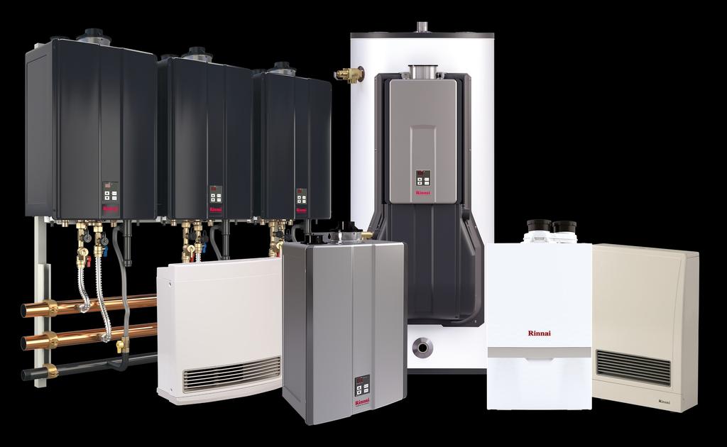
100 100 Rinnai M-Series Condensing Solo Boiler Installation and Operation Manual (02) 07/2018
Demand Duo. Residential Hybrid Water Heating System RHS199100SE INSTALLATION AND OPERATION MANUAL rinnai.us
 rinnai.us 1-800-621-9419 INSTALLATION AND OPERATION MANUAL Demand Duo Residential Hybrid Water Heating System Demand Duo Model RHS199100SE WARNING If the information in these instructions is not followed
Direct Vent Tankless Water Heater Installation and Operation Manual
 Direct Vent Tankless Water Heater Installation and Operation Manual FOR INDOOR APPLICATIONS ONLY RUC80i... REU-KBD2530FFUD-US RUC90i... REU-KBD2934FFUD-US RUC98i... REU-KBD3237FFUD-US FOR OUTDOOR APPLICATIONS
Polypropylene (PP) Common Venting
 Common Venting") 100000557 REVC 04/18 1-800-621-9419 Rinnai Customer Care. Monday to Friday between 8 AM to 8 PM ET rinnai.us INSTALLATION INSTRUCTIONS Polypropylene (PP) Common Venting 3, 4, 6 Diameters CERTIFIED FOR
100000557 REVC 04/18 1-800-621-9419 Rinnai Customer Care. Monday to Friday between 8 AM to 8 PM ET rinnai.us INSTALLATION INSTRUCTIONS Polypropylene (PP) Common Venting 3, 4, 6 Diameters CERTIFIED FOR
CONVERSION TO PROPANE MANUAL M-Series Condensing Boiler. Wall-Mounted, Gas-Fired Boiler
 rinnai.us 1-800-621-9419 CONVERSION TO PROPANE MANUAL M-Series Condensing Boiler Wall-Mounted, Gas-Fired Boiler For the Conversion from Natural Gas (NG) to Liquid Propane Gas (LPG) MODELS M060C M090C M120C
Table of Contents. Safety Definitions DANGER WARNING CAUTION
 GI-IM044En-0415 Table of Contents Table of Contents... 2 Safety Definitions... 2 Safety Behaviors and Practices for the Consumer and Installer... 3 Installation Instructions (for the licensed professional)...
Common Vent System. Common Vent System
 Common Vent System Common Vent System Installation Manual Independently tested and approved by CSA Keep this manual for future reference whenever maintenance or service is required. WARNING If the information
INSTALLATION MANUAL Tankless Rack System
 rinnai.us 1-800-621-9419 INSTALLATION MANUAL Tankless Rack System Lift, Position and Secure the Rack Vent the Water Heaters Connect Plumbing Connect Gas Connect Power Installation section (page 33) Venting
C1050ES Tankless Water Heater
 Engineering Submittal Sheet Dimensions and Connections B C D C Combustion air inlet Exhaust outlet Optional combustion air inlet Top view Top view A E F Hot water outlet Cold water inlet Inlet water filter
DIRECT VENT TANKLESS WATER HEATERS OWNER S MANUAL INSTALLATION AND OPERATING INSTRUCTIONS
 DIRECT VENT TANKLESS WATER HEATERS OWNER S MANUAL INSTALLATION AND OPERATING INSTRUCTIONS FOR INDOOR APPLICATIONS ONLY UGTC-199N UGTC-199P UGTC-152N UGTC-152P If the information in these instructions is
C1210ES Tankless Water Heater
 Engineering Submittal Sheet Dimensions and Connections B C D C Combustion air inlet Exhaust outlet Optional combustion air inlet Top view Top view A E Hot water outlet Cold water inlet F H J C I K G Front
Installation and Operation Instructions Manual
 To the Installer: Please attach these instructions next to the water heater. To the Consumer: Please read these and all component instructions and keep for future reference. Installation and Operation
Installation Instructions T 9822 Gas Dryer. en - US, CA. To prevent accidents
 Installation Instructions T 9822 Gas Dryer To prevent accidents en - US, CA and appliance damage read these instructions before installation or use. M.-Nr. 07 431 110 2 WARNING For your safety the information
940ES Tankless Water Heater
 Engineering Submittal Sheet Overview and Certifications LOW-LEAD U P C C US Massachusetts Plumbing Board Approved Engineering Specifications Water heater shall be a Model Therm 940 ES. Plant shall consist
940ES Tankless Water Heater
 Engineering Submittal Sheet Dimensions and Connections B C D C Combustion air inlet Exhaust outlet Optional combustion air inlet Top view Top view A Hot water outlet Cold water inlet E F Front view Side
Installation and Operation Instructions Manual
 To the Installer: Please attach these instructions next to the water heater. To the Consumer: Please read these and all component instructions and keep for future reference. Installation and Operation
Commercial Hybrid System Installation and Operation Manual
 Commercial Hybrid System Installation and Operation Manual FOR INDOOR APPLICATIONS ONLY CHS199100... 119 gallon, 199,000 BTU The Commercial Hybrid System is assembled with multiple and separately certified
ML180UH SERIES GAS FURNACE WARNING WARNING
 2017 Lennox Industries Inc. Dallas, Texas, USA 506525-01 04/2017 Supersedes 10/2015 ML180UH SERIES GAS FURNACE Improper installation, adjustment, alteration, service or maintenance can cause property damage,
On-Demand Water Heater Installation Manual and Owner s Guide
 On-Demand Water Heater Installation Manual and Owner s Guide ANSI Z21.10.3 CSA 4.3 R D R 510C model only Models 110C 310C 510C WARNING If the information in these instructions is not followed exactly,
Universal Fire Tube Boiler Wall Mount Models
 Universal Fire Tube Boiler Wall Mount Models USER S INFORMATION MANUAL Models WBRU**80W / 100W / 120W / 140W / 175W / 199W **NG denotes Natural Gas Model, LP Denotes Propane Model Heat Exchanger Bears
Phone: Address: A Industrial RD Summerville, SC 29483
 WARNING: If the information in these instructions is not followed exactly, a fire or explosion may result causing property damage, personal injury or death. Do not store or use gasoline or other flammable
Commercial Hybrid System Installation and Operation Manual
 Commercial Hybrid System Installation and Operation Manual FOR INDOOR APPLICATIONS ONLY CHS199100... 119 gallon, 199,000 BTU The Commercial Hybrid System is assembled with multiple and separately certified
Bosch Greentherm T9800 SE 199 Gas Tankless Water Heater
 Engineering Submittal Sheet Product Overview & Certifications Engineering Specifications The system shall consist of gas tankless water heater model Greentherm T9800 SE 199 as manufactured by Bosch Thermotechnology.
USER S INFORMATION MANUAL
 2017 Lennox Industries Inc. Dallas, Texas, USA 506737-01 04/2017 Supersedes 03/2017 USER S INFORMATION MANUAL EL195UHE SERIES GAS FURNACE Improper installation, adjustment, alteration, service or maintenance
SAFE DRINKING WATER AND TOXIC ENFORCEMENT ACT
 Installation instructions for your new Spacemaker Laundry WSM2780 Gas Before you begin Read these instructions completely and carefully. IMPORTANT OBSERVE ALL GOVERNING CODES AND ORDINANCES. Note to Installer
Installation instructions for the T 9820 Gas Dryer
 Installation instructions for the T 9820 Gas Dryer The T 9820 gas dryer is only approved for use in the USA and Canada. It is not approved for use in Mexico. To prevent accidents en - US, CA and machine
Installation Manual REVOLUTION WATER HEATER. Model VRP-150 VRP-199 VRS-150 VRS-199
 REVOLUTION WATER HEATER Installation Manual Model VRP-150 VRP-199 VRS-150 VRS-199 Keep this manual near the water heater for future reference whenever maintance or service is required. * Lead Free * The
Gas Fired Residential Combi Boiler Floor and Wall Mount Models
 Gas Fired Residential Combi Boiler Floor and Wall Mount Models USER S INFORMATION MANUAL Models WBRC**140W WBRC**199W WBRC**140F WBRC**199F ** NG Refers to Natural Gas Operation LP Refers to Propane Gas
INSTALLATION INSTRUCTIONS
 INSTALLATION INSTRUCTIONS G1D91BT, CG90TB, & G1D93BT High Efficiency 90+ Condensing Gas Furnace WARNING Improper installation, adjustment, alteration, service, or maintenance can cause injury or property
VSL II QUICK START GUIDE
 This Quick Start Guide must be left with owner and should be hung on or adjacent to the boiler for reference. VSL II QUICK START GUIDE DIRECT-VENT SEALED COMBUSTION CONDENSING BOILER ~ GAS-FIRED BOILER
WARNING FIRE OR EXPLOSION HAZARD.
 2017 Lennox Industries Inc. Dallas, Texas, USA 506897-01 04/2017 Supersedes 10/2015 EL280DF SERIES GAS FURNACE Improper installation, adjustment, alteration, service or maintenance can cause property damage,
EL195UHE SERIES GAS FURNACE WARNING WARNING
 2012 Lennox Industries Inc. Dallas, Texas, USA 506737-01 12/2012 Supersedes 06/2011 EL195UHE SERIES GAS FURNACE Improper installation, adjustment, alteration, service or maintenance can cause property
Residential Gas Hybrid Water Heater
 Residential Gas Hybrid Water Heater USER S INFORMATION MANUAL WGRGH20NG75F / WGRGH20NG76F / WGRGH20NG100F WGRGHNG75F / WGRGHNG76F / WGRGHNG100F Models* *A suffix of LP denotes propane gas NOTICE: Westinghouse
GAS COOKTOP INSTALLATION INSTRUCTIONS BEFORE YOU BEGIN. IMPORTANT Save these instructions for local electrical inspector s use.
 GAS COOKTOP INSTALLATION INSTRUCTIONS Please read this guide thoroughly before installation. To contact LG Electronics, 24 hours a day, 7 days a week: 1-800-243-0000 (U.S.A.) 1-888-542-2623 (Canada) Or
Greentherm 9800 SE 160/199 SEC 199
 Danger: If the information in this manual is not followed exactly, a fire or explosion may result causing property damage, personal injury or death. Do not store or use gasoline or other flammable vapors
SLP98UH SERIES VARIABLE CAPACITY GAS FURNACE WARNING WARNING
 2015 Lennox Industries Inc. Dallas, Texas, USA 506443-01 01/2015 Supersedes 08/2012 SLP98UH SERIES VARIABLE CAPACITY GAS FURNACE Improper installation, adjustment, alteration, service or maintenance can
Tankless Water Heater
 Tankless Water Heater Installation and Operation Manual INTERNAL (INDOOR) MODELS: Full-length French and Spanish versions available online at rinnai.us CU199i (REU-N3237FFC-US) CU160i (REU-N2530FFC-US)
Commercial High Efficiency Water Heater
 Commercial High Efficiency Water Heater USE & CARE MANUAL WITH INSTALLATION INSTRUCTIONS FOR THE CONTRACTOR DESIGN CERTIFIED Recognize this symbol as an Indication of Important Safety Information Do Not
HYBRID WATER HEATER Installation Manual
 HYBRID WATER HEATER Installation Manual Model VH-199 Keep this manual near the water heater for future reference whenver maintenance or service is required. * Lead Free WARNING: If the information in these
User s Information Manual
 User s Information Manual Gas-Fired Storage Water Heater, Tankless Water Heater, Heating Appliance, and Combination Appliance Models IF THE INFORMATION IN THIS MANUAL IS NOT FOLLOWED EXACTLY, A FIRE OR
User s Information Manual
 Gas-fired Water boiler Series 2 NOTICE: Series 1/Series 2 identification Read the boiler rating plate to determine the series number. The rating plate is located on the right side of the boiler. User s
OPERATING INSTRUCTIONS AND OWNER S MANUAL
 OPERATING INSTRUCTIONS AND OWNER S MANUAL MR. HEATER READ INSTRUCTIONS CAREFULLY: Read and follow all instructions. Place instructions in a safe place for future reference. Do not allow anyone who has
Tankless Water Heater
 Tankless Water Heater USER S INFORMATION MANUAL Models WGRT**150 / WGRT**199 / WGRTC**199 **A suffix of LP denotes propane gas **A suffix of NG denotes natural gas NOTICE: Westinghouse reserves the right
EL296UHV SERIES GAS FURNACE WARNING WARNING
 2011 Lennox Industries Inc. Dallas, Texas, USA 506769 01 08/2012 Supersedes 10/2011 EL296UHV SERIES GAS FURNACE Improper installation, adjustment, alteration, service or maintenance can cause property
Installation Guide. 5 Series VGC and VGSU Built-In Gas Cooktops
 Installation Guide 5 Series VGC and VGSU Built-In Gas Cooktops Table of Contents Warnings & Important Safety Instructions 3 Dimensions VGC Cooktops 6 Specifications VGC Cooktops 7 Dimensions VGSU Cooktops
Installation Instructions Dual Fuel Ranges
 Installation Instructions Dual Fuel Ranges E30DF74EPS E36DF76EPS E48DF76EPS 5995447082 2 Safety IMPORTANT SAFETY INSTRUCTIONS Safety Precautions Do not attempt to install or operate your unit until you
Installation Manual CONDENSING TANKLESS GAS WATER HEATER DANGER WARNING CAUTION CAUTION
 Installation Manual NORITZ AMERICA CORPORATION CONDENSING TANKLESS GAS WATER HEATER NCC300DV (GQ-C5032WZ-FF US) (Indoor Installation) Potential dangers from accidents during installation and use are divided
Installation Instructions
 Installation Instructions Gas Cooktop KM 360 To prevent accidents and machine damage, read these instructions before installation or use. UV M.-Nr. 06 390 460 WARNING: If the information in this manual
INSTALLATION AND OPERATION MANUAL GAS SKILLETS MODELS: GTS-30 GTS-40
 INSTALLATION AND OPERATION MANUAL GAS SKILLETS MODELS: GTS-30 GTS-40 CROWN FOOD SERVICE EQUIPMENT LTD. 70 OAKDALE ROAD, DOWNSVIEW, (TORONTO), ONTARIO, CANADA, M3N 1V9 TELEPHONE: (416) 746-2358, FAX: (416)
HIGH-EFFICIENCY UPFLOW FURNACE INSTALLER'S INFORMATION MANUAL
 HIGH-EFFICIENCY UPFLOW FURNACE INSTALLER'S INFORMATION MANUAL Model Numbers WMVSA054NH3R WMVSA072NH3R, WMVSA072NH4R WMVSA090NH3R, WMVSA090NH4R WMVSA108NH5R DESIGN WMVSA126NH5R C E R TI F I ED ATTENTION,
User s Information Manual
 User s Information Manual CONDENSING GAS BOILER 220/299/300/399 If the information in this manual is not followed exactly, a fire or explosion may result, causing property damage, personal injury or loss
WARNING FIRE OR EXPLOSION HAZARD.
 2017 Lennox Industries Inc. Dallas, Texas, USA 506698-01 04/2017 Supersedes 10/2015 SL280DFV SERIES GAS FURNACE Improper installation, adjustment, alteration, service or maintenance can cause property
Vent Supplement Ultra-80, -105, -155, -230 & -310
 Gas-fired water boiler Vent Supplement Ultra-80, -105, -155, -230 & -310 Installation of: Vent piping Air piping with This document must only be used by a qualified heating installer/service technician.
RTG 199 HE INDOOR MODEL. RTG 199 HEN - Natural Gas RTG 199 HEX - Propane (LP Gas) Installation and Operation instructions
 Installation and Operation instructions") Installation and Operation instructions INDOOR MODEL RTG 199 HE Warning: If the information in this manual is not followed exactly, a fire or explosion may result causing property damage, personal injury
Installation and Operation instructions INDOOR MODEL RTG 199 HE Warning: If the information in this manual is not followed exactly, a fire or explosion may result causing property damage, personal injury
710 / 710 ASME (T-M32/ T-M32 ASME) On-Demand Water Heater Installation Manual and Owner s Guide
 On-Demand Water Heater Installation Manual and Owner s Guide") 710 / 710 ASME (T-M32/ T-M32 ASME) On-Demand Water Heater Installation Manual and Owner s Guide ANSI Z21.10.3 and CSA 4.3 HLW For supplying potable hot water ASME model ONLY WARNING If the information
710 / 710 ASME (T-M32/ T-M32 ASME) On-Demand Water Heater Installation Manual and Owner s Guide ANSI Z21.10.3 and CSA 4.3 HLW For supplying potable hot water ASME model ONLY WARNING If the information
Direct Exhaust Venting Kit Instructions
 CONDENSING GAS BOILER 220/299/300/399 Direct Exhaust Venting Kit Instructions Evergreen 220/299/300/399 Kit part number 383-500-769 STOP! Read before proceeding Hazard definitions The following defined
INSTALLATION GUIDE Dual Fuel Ranges
 INSTALLATION GUIDE Dual Fuel Ranges Contents Wolf Dual Fuel Ranges......................... 3 Safety Instructions............................ 4 Dual Fuel Range Specifications.................. 5 Dual Fuel
Viking Installation Guide
 Viking Installation Guide Viking Range Corporation Front Street Greenwood, Mississippi 38930 USA (66) 455-00 For product information, call -888-VIKING (845-464) or visit the Viking Web site at vikingrange.com
INSTALLATION AND OPERATING INSTRUCTIONS TABLE OF CONTENTS IMPORTANT
 C US This manual must be left with owner and should be hung on or adjacent to the boilerfor reference. COMMON VENTING MODELS CHS-300 through CHS-399 INSTALLATION AND OPERATING INSTRUCTIONS TABLE OF CONTENTS
USER S INFORMATION MANUAL
 USER S INFORMATION MANUAL UPFLOW & DOWNFLOW/HORIZONTAL CONDENSING GAS FURNACES SAFETY Recognize this symbol as an indication of Important Safety Information If not installed, operated and maintained in
PVC, CPVC, PP & SS Vent Supplement
 PVC, CPVC, PP & SS Vent Supplement L I S T E D This document is intended to be used by a qualified heating contractor or service technician. Read all instructions within this document and within the PRESTIGE
On-Demand Water Heater Installation Manual and Owner s Guide
 On-Demand Water Heater Installation Manual and Owner s Guide R D R ANSI Z21.10.3 CSA 4.3 510C model only Models 110C 310C 510C WARNING If the information in these instructions is not followed exactly,
Installation Manual CONDENSING TANKLESS GAS WATER HEATER DANGER WARNING CAUTION CAUTION
 Installation Manual NORITZ AMERICA CORPORATION CONDENSING TANKLESS GAS WATER HEATER NRC98DV (GQ-C2857WS-FF US) (Indoor Installation) Potential dangers from accidents during installation and use are divided
Tankless Water Heater
 Residential Indoor and Outdoor Gas R Installation and Operating Instruction Manual With Installation Instructions for the Installer Tankless Water Heater Indoor Water Heater Outdoor Water Heater The purpose
TL-Pro 175C/199C INDOOR MODEL. TL-Pro 175/199 C - Natural Gas TL-Pro 175/199 C- Propane (LP Gas) Installation and Operation instructions
 Installation and Operation instructions") Installation and Operation instructions INDOOR MODEL TL-Pro 175C/199C Warning: If the information in this manual is not followed exactly, a fire or explosion may result causing property damage, personal
Installation and Operation instructions INDOOR MODEL TL-Pro 175C/199C Warning: If the information in this manual is not followed exactly, a fire or explosion may result causing property damage, personal
P.O. Box , Dallas, TX USER'S INFORMATION MANUAL Single-Stage Warm Air Gas Furnaces
 P.O. Box 799900, Dallas, TX 75379-9900 USER'S INFORMATION MANUAL Single-Stage Warm Air Gas Furnaces This is a safety alert symbol and should never be ignored. When you see this symbol on labels or in manuals,
Installation Instructions
 Residential Gas Furnaces Installation Instructions *RA Full Size Series 80+ High Efficiency Upflow/Horizontal *RK Full Size Series 80+ High Efficiency Downflow *RA 80+ Upflow/Horizontal *RK 80+ Downflow!
Commercial Indoor and Outdoor Gas Tankless Water Heater
 Installation and Operating Instruction Manual R With Installation Instructions for the Installer Commercial Indoor and Outdoor Gas Tankless Water Heater Indoor Water Heater Outdoor Water Heater The purpose
Installation Instructions
 Installation Instructions Gas Cooktop KM 404 KM 406 To prevent accidents and machine damage, read the operating instructions before installation or use. UV M.-Nr. 05 060 881 WARNING: If the information
HIGH-EFFICIENCY DOWNFLOW / HORIZONTAL FURNACE INSTALLER'S INFORMATION MANUAL
 HIGH-EFFICIENCY DOWNFLOW / HORIZONTAL FURNACE INSTALLER'S INFORMATION MANUAL DESI GN C E R TI F I ED DOWNFLOW POSITION SHOWN ATTENTION, INSTALLER! After installing the furnace, show the user how to turn
Sun Bandit Hybrid Gas Water Heater Installation, Operation and Maintenance Manual
 Sun Bandit Hybrid Gas Water Heater Installation, Operation and Maintenance Manual IMPORTANT! Record all product serial numbers BEFORE installing your Sun Bandit Solar Hybrid Energy System #23397 Rev4 12/2016
CYLINDER NOT INCLUDED
 OPERATING INSTRUCTIONS AND OWNER S MANUAL Model # HS125NG / MH125LP / HS125LP READ INSTRUCTIONS CAREFULLY: Read and follow all instructions. Place instructions in a safe place for future reference. Do
Elite. User s Information Manual. Elite and Elite VWH* All Models
 Elite User s Information Manual Elite and Elite VWH* All Models Heat Exchanger Bears the ASME H Stamp IF THE INFORMATION IN THIS MANUAL IS NOT FOLLOWED EXACTLY, A FIRE OR EXPLOSION MAY RESULT, CAUSING
RESIDENTIAL POWER VENT GAS-FIRED WATER HEATERS OWNER S MANUAL INSTALLATION AND OPERATING INSTRUCTIONS
 RESIDENTIAL POWER VENT GAS-FIRED WATER HEATERS (EQUIPPED WITH FVIR TECHNOLOGY) OWNER S MANUAL INSTALLATION AND OPERATING INSTRUCTIONS This water heater IS NOT design certified for installation in a manufactured
Use & Care Manual. Residential Gas - FVIR Certified Direct Vent Water Heaters. With Installation Instructions for the Installer
 ! WARNING: This water heater is not suitable for use in manufactured (mobile) homes! Use & Care Manual With Installation Instructions for the Installer Residential Gas - FVIR Certified Direct Vent Water
G61MPV SERIES GAS FURNACE WARNING
 2003 Lennox Industries Inc. Dallas, Texas, USA 504,809M 03/2009 Supersedes 06/2003 G61MPV SERIES GAS FURNACE Litho U.S.A. FIRE OR EXPLOSION HAZARD. Failure to follow safety warnings exactly could result
VSL II QUICK START GUIDE
 This Quick Start Guide must be left with owner and should be hung on or adjacent to the boiler for reference. VSL II QUICK START GUIDE DIRECT-VENT SEALED COMBUSTION CONDENSING BOILER ~ GAS-FIRED BOILER
NCC199CDV Commercial Water Heating System Installation Manual
 NCC199CDV Commercial Water Heating System Installation Manual -Additional information can be obtained from the appliance manual. Floor Mount Rack (CDV Units) 6 Water Heaters Floor Mount Rack (w/ VC-6)
! This is the safety alert symbol. Recognize this symbol
 ! Warning: This water heater is not suitable for use in manufactured (mobile) homes! Use & Care Manual With Installation Instructions for the Installer Residential Gas - FVIR Certified PowerDirect Vent
C1210ESC Tankless Water Heater
 Engineering Submittal Sheet Overview and ertifications L W LOW-LEAD U P US Massachusetts Plumbing Board Approved Engineering Specifications Water heater shall be a Model Therm 1210 ES. Plant shall consist
Aqua Balance. User s Information Manual. WMB-155C Wall Mount Gas-Fired Combination Boiler Heating and Domestic Hot Water
 Aqua Balance WMB-155C Wall Mount Gas-Fired Combination Boiler Heating and Domestic Hot Water User s Information Manual * Low Lead Content If the information in this manual is not followed exactly, a fire
910 / 910 ASME (T-M50/T-M50 ASME) On-Demand Water Heater Installation Manual and Owner s Guide
 On-Demand Water Heater Installation Manual and Owner s Guide") 910 / 910 ASME (T-M50/T-M50 ASME) On-Demand Water Heater Installation Manual and Owner s Guide For supplying potable hot water ANSI Z21.10.3 and CSA 4.3 HLW ASME model ONLY WARNING If the information in
910 / 910 ASME (T-M50/T-M50 ASME) On-Demand Water Heater Installation Manual and Owner s Guide For supplying potable hot water ANSI Z21.10.3 and CSA 4.3 HLW ASME model ONLY WARNING If the information in
User s Information Manual
 User s Information Manual Gas-Fired Water Boilers With or without Aqua Logic (CWH) Now available Matching High Performance Companion Water Heater (Unit sold separately) If the information in this manual
Direct Vent Wall Furnace Installation and Operation Manual
 EX17CT... (RHFE-434FTA2) EX22CT... (RHFE-559FTA2) Direct Vent Wall Furnace Installation and Operation Manual Installer: Leave this manual with the appliance. Consumer: Retain this manual for future reference.
Installation & Operation Manual Models:
 AWII-I-O Rev G Installation & Operation Manual Models: 151-801 : If the information in this manual is not followed exactly, a fire or explosion may result causing property damage, personal injury or loss
Tankless Water Heater
 Indoor and Outdoor Gas Use & Care Manual With Installation Instructions for the Installer Tankless Water Heater Models: Indoor Water Heater Outdoor Water Heater PH-16 (FISN)(FISP) PH20R-(IFSN)(IFSP)(OFN)(OFP)
C 950 / 1050 ES C 950 / 1050 ES - Natural Gas / C 950 / 1050 ES - Liquefied Petroleum (LP) Gas
 Gas") Danger: If the information in this manual is not followed exactly, a fire or explosion may result causing property damage, personal injury or death. Do not store or use gasoline or other flammable vapors
Danger: If the information in this manual is not followed exactly, a fire or explosion may result causing property damage, personal injury or death. Do not store or use gasoline or other flammable vapors
INSTALLATION INSTRUCTIONS G2D93CT, G2D93CU, G2D95CT, & G2D95CU High Efficiency Multiposition Gas Furnace with System Sentry Control System WARNING
 INSTALLATION INSTRUCTIONS G2D93CT, G2D93CU, G2D95CT, & G2D95CU High Efficiency Multiposition Gas Furnace with System Sentry Control System Save these instructions for future reference WARNING Improper
Using it in an enclosed space can kill you.
 38 X 56 GAS FIRE PIT - OWNER S MANUAL Carlisle Chat Fire Table Base Model # 00GBC7 (6877B) Fits 6877A Carlisle Chat Fire Table Top For Propane and *Natural Gas (*See Page 7) Certified to CSA International
GAS COOKTOP MODELS: CTG365D, CTG305D, CTG304D TO REDUCE THE RISK OF FIRE, ELECTRIC SHOCK, OR INJURY TO PERSONS, OBSERVE THE FOLLOWING
 By CNP INDUSTRIES, INC. P.O. Box 18645 Anaheim, Ca 92817 (877) 387-6721 INSTALLATION INSTRUCTIONS GAS COOKTOP MODELS: CTG365D, CTG305D, CTG304D IMPORTANT: Before beginning installation please read these
Do not use this vent pipe or fittings for venting incinerators of any kind.
 ! CAUTION! Do not use this vent pipe or fittings for venting incinerators of any kind. C.S.A. Certified For Natural Gas Or Propane Tested For 100 LBS. ASME Working Pressure For correct installation of
RESIDENTIAL POWER DIRECT VENT GAS-FIRED WATER HEATERS (EQUIPPED WITH FVIR TECHNOLOGY) OWNER S MANUAL INSTALLATION AND OPERATING INSTRUCTIONS
 OWNER S MANUAL INSTALLATION AND OPERATING INSTRUCTIONS") RESIDENTIAL POWER DIRECT VENT GAS-FIRED WATER HEATERS (EQUIPPED WITH FVIR TECHNOLOGY) OWNER S MANUAL INSTALLATION AND OPERATING INSTRUCTIONS This water heater IS NOT design certified for installation in
RESIDENTIAL POWER DIRECT VENT GAS-FIRED WATER HEATERS (EQUIPPED WITH FVIR TECHNOLOGY) OWNER S MANUAL INSTALLATION AND OPERATING INSTRUCTIONS This water heater IS NOT design certified for installation in
EL195DFE SERIES GAS FURNACE WARNING
 2011 Lennox Industries Inc. Dallas, Texas, USA 506739 01 06/2011 EL195DFE SERIES GAS FURNACE Litho U.S.A. FIRE OR EXPLOSION HAZARD. Failure to follow safety warnings exactly could result in serious injury,
USER S INFORMATION MANUAL
 USER S INFORMATION MANUAL UPFLOW, DOWNFLOW, UPFLOW/HORIZONTAL & HORIZONTAL ONLY INDUCED DRAFT GAS FURNACES Recognize this symbol as an indication of Important Safety Information If the information in this
User s Information Manual Models:
 FB-USER Rev C User s Information Manual Models:1.5-5.0 WARNING: If the information in these instructions is not followed exactly, a fire or explosion may result causing property damage, personal injury
CAUTION. Requests to Installers In order to use the water heater safely, read this installation manual carefully, and follow the installation
 Installation Manual NORITZ AMERICA CORPORATION CONDENSING TANKLESS GAS WATER HEATER NRC66-DV (Indoor Installation) Potential dangers from accidents during installation and use are divided into the following
USER'S INFORMATION MANUAL
 USER'S INFORMATION MANUAL WARNING: If the information in this manual is not followed exactly, a fire or explosion may result causing property damage, personal injury or loss of life. Do not store or use
GAS COOKTOP INSTALLATION INSTRUCTIONS
 INSTALLATION AND SERVICE MUST BE PERFORMED BY A QUALIFIED INSTALLER. IMPORTANT: SAVE FOR LOCAL ELECTRICAL INSPECTOR'S USE. READ AND SAVE THESE INSTRUCTIONS FOR FUTURE REFERENCE. WARNING If the information
NAVIEN AMERICA INC FITCH AVENUE IRVINE, CALIFORNIA, USA
 Navien America Inc. Specification Details for the Navien models: CR-210 CR-210A For Indoor Installation Only For Potable Water Heating and Space Heating NAVIEN AMERICA INC. 17855 FITCH AVENUE IRVINE, CALIFORNIA,
INSTALLATION AND SERVICE MANUAL
 INSTALLATION AND SERVICE MANUAL HORIZONTAL COMBUSTION AIR INLET KITS CATEGORY III VENTING FOR SEPARATED COMBUSTION TUBULAR GAS FIRED UNIT HEATERS USE 5 INCH KIT FOR UNITS WITH CAPACITIES 100,000 TO 250,000
Installation Manual REVOLUTION CONDENSING COMBI-BOILERS. For Your Safety
 REVOLUTION CONDENSING COMBI-BOILERS Installation Manual Model VRC-80 VRC-100 VRC-120 VRC-140 Keep this manual near this boiler for future reference whenever maintance or service is required. For Your Safety