AGA TOTAL CONTROL. Model No. - TC3 & TC5
|
|
|
- Elvin Perkins
- 5 years ago
- Views:
Transcription


1 AGA TOTAL CONTROL Model No. - TC3 & TC5 Installation Guide REMEMBER: when replacing a part on this appliance, use only replacement parts that you can be assured conform to the safety and performance specification that we require. Do not use reconditioned or copy parts that have not been clearly authorised by AGA. PLEASE READ THESE INSTRUCTIONS BEFORE COMMENCING SITE SURVEY OR INSTALLING THIS APPLIANCE. IMPORTANT : SAVE INSTRUCTIONS FOR THE LOCAL INSPECTORS USE CUSTOMER: KEEP THESE INSTRUCTIONS FOR FUTURE REFERENCE For use in USA/Canada 11/12 EINS
2 CONTENTS SECTION PAGE GENERAL NOTES 3 DELIVERY REQUIREMENTS 3 GENERAL INSTALLATION REQUIREMENTS 3 APPLIANCE DIMENSIONS - AGA TC3 4 APPLIANCE DIMENSIONS - AGA TC5 5 INSTALLATION 6 CONNECTING TO THE POWER SUPPLY - AGA TC3 8 POWER SUPPLY - HOTCUPBOARD (AGA TC5) 9 MAINS SUPPLY LOCATION - AGA TC3 10 MAINS SUPPLY LOCATION - AGA TC5 11 HOTCUPBOARD INSTALLATION 12 HANDRAIL CONNECTION - AGA TC3 17 MAINS CORD AND WIRING DIAGRAM - AGA TC3 18 WIRING DIAGRAM - AGA TC5 (HOTCUPBOARD) 19 INSTRUCTIONS 20 CAUTION: THIS UNIT IS HEAVY, PROPER EQUIPMENT AND ADEQUATE MANPOWER MUST BE USED IN MOVING THE RANGE TO AVOID DAMAGE TO THE UNIT OR THE FLOOR 2
3 GENERAL NOTES NOTE: THESE INSTALLATION INSTRUCTIONS SHOULD BE LEFT WITH THE APPLIANCE AND THE USER TO RETAIN FOR FUTURE REFERENCE. Before installation of an AGA can be made, the site is inspected for suitability by an authorized AGA distributor and corrected where necessary to conform with local or regional electrical codes. USA Model Number AGA TC3 FCC ID: A2M-AGA-TC3 FCC ID: A2M-AGA-TC3CKR This device complies with part 15 of the FCC Rules. Operation is subject to the following two conditions: (1) This device may not cause harmful interference, and (2) this device must accept any interference received, including interference that may cause undesired operation. CANADA Model Number AGA TC3 IC: 10181A-AGATC3CKR Model Number AE4M IC: 10181A-AGATC3 The AGA TC3 arrives on 1 pallet. DELIVERY REQUIREMENTS The AGA TC5 (Hotcupboard Option) arrives on 2 pallets. There must be access to the kitchen to manipulate a foot print of 39 9 /16 (1005mm) x 29 1 /8 (740mm). A wooden template (skate with castor wheels) of dimensions 39 9 /16 (1005mm) x 29 1 /8 740mm could be used to check if the AGA Total Control fully built appliance is able to fit through the property grounds and doors into its installation position in the kitchen. It must also be considered that the height of the appliance is 37 6 /8 (960mm) off pallet and 43 2 /8 (1100mm) on the pallet, so high level obstacles/restrictions must not be overlooked. If this skate/template can be manipulated through the property grounds and doors into position, then the AGA Total Control can be installed as intended with no re-work. GENERAL INSTALLATION REQUIREMENTS The installation of the range must be in accordance with the relevant requirements of the local Wiring and Building Regulations. It should be in accordance also with any relevant requirements of the Local Authority. In your own interest and that of safety to comply with the law, all appliances should be installed by an authorized AGA distributor in accordance with the relevant regulations. 3
4 APPLIANCE DIMENSIONS - AGA TC3 RH SIDE VIEW FRONT VIEW LH SIDE VIEW PLAN VIEW MINIMUM WALL POSITION MINIMUM WALL POSITION Fig. 1 DESN A B C D E F G H J K mm ins 38 7 / / / / / / / /2 4 9 /16 3 /8 Cooker Dimensions When surveying for a cooker installation the actual clearance required for the body of the appliance should be increased by 3/8 (10mm) beyond the figures quoted above. This allows safe margin to take into account the natural dimensional variations found in major castings. In particular the width across the appliance recess could be critical. APPLIANCE WEIGHT Model: AGA Total Control (TC3) lbs (370 Kg) PACKAGING WEIGHT 1135 lbs (515 Kg) DATA PLATE LOCATED BEHIND BOTTOM PLINTH. 4
5 APPLIANCE DIMENSIONS - AGA TC5 Fig. 2 DESN A B C D E F G H J K L mm ins / / / / / / / /2 4 9 /16 3 / /32 Cooker Dimensions When surveying for a cooker installation the actual clearance required for the body of the appliance should be increased by 10mm beyond the figures quote above. This allows safe margin to take into account the natural dimensional variations found in major castings. In particular the width across the appliance recess could be critical. APPLIANCE WEIGHT Model: AGA Total Control (TC3) lbs (370 Kg) Hotcupboard - 110kg 5
6 INSTALLATION Range Base or Hearth It is essential that the base or hearth on which the range stands should be level and be capable of supporting the total weight of the range. The base of the built-in AGA plinth must be level and sit above finished floor height for service access. Plinth The front plinth cover is removable and must not be obstructed by flooring or tiles. If necessary the cooker must be raised by the thickness of the tiles to ensure the plinth can be removed. Minimum Clearance to Combustibles A gap of at least 1 /2 must be observed between the rear of the top plate, and the wall behind the appliance. If the rear wall is of combustible material there must be a gap of 1 (25mm). Side Clearances A 1 /8 (3mm) gap is required each side between the cooker top plate and adjoining work surfaces that may be fitted, this is to allow for the safe removal of the top plate should this be required at a later date. Where cookers are fitted against side walls a 4 9 /16 (116mm) side clearance is required on the right and left hand side for oven doors access. If the AGA is to be installed in a brick recess, then the minimum clearance should be increased by at least 3 /8 (10mm), to allow for the walls not being square. In addition a minimum clearance of 39 1 /2 (1000mm) must be available at the front of the cooker to enable the cooker to be serviced. Tiling When the cooker is to stand in a recess or against a wall which is to be tiled, under no circumstances should the tiles overlap the cooker top plate, access to remove the hotplate must be allowed for servicing at a later date. Overhead Cabinets To eliminate the risk of burns or fires by reaching over hot surface units, cabinet storage space located above the surface units should be avoided. Range Hoods It is recommended that this AGA is fitted with a range hood. The AGA venting system is located on top of the AGA between the two hotplates, and is designed for venting the moisture from the ovens. The cooker hood should be positioned not less than the minimum height as recommended by the manufacturer, from the top of the AGA. 6
7 NOTE: ANY OVERHEAD FITTED CABINETS MUST NOT EXCEED 13 PROJECTED DEPTH ABOVE THE RANGE. DIM D TO BE NOT LESS THAN THE NORMAL WIDTH OF THE APPLIANCE. Fig. 3 DESN
8 CONNECTION TO THE POWER SUPPLY - AGA TC3 Electric Shock Hazard Rating Plate is located behind removable plinth, see Fig. 4. Electrical Grounding is required on this appliance. DO NOT connect to the electrical supply until the appliance is permanently grounded. Disconnect the power to the junction box before making the electrical connection. This appliance must be connected to a grounded metallic permanent supply or a grounding connector should be connected to the grounding terminal or wire lead on the appliance. Failure to follow these instructions could result in death or serious injury. This range must be supplied with a 240V, 60Hz power supply and connected to an individual, properly grounded branch circuit protected by a circuit breaker or time delay fuse. At 240V, it has a maximum load of 36 amps. Electric hook-up must be done by a licensed electrician. This unit must be installed according to local code, or in the absence of local codes, the National Electrical Code for the country of installation. Wire sizes (COPPER WIRE ONLY) and connections must conform with the rating of the range (36-amperes). l l l Product installation requires a separate (not shared) 240v/40 amp circuit protected by an appropriate branch circuit supply. A time-delay fuse or circuit breaker is required. The service cord provided on your product is fitted with a standard four (4) conductor type 14-50P plug, (matching receptacle 14-50R). l The wiring diagram is located on Page 18. The method of connection to the mains electricity supply must facilitate complete electrical isolation of the appliance. The mains connection and isolation should not be positioned above the range and must be positioned within the area defined in Fig. 4, Page 10. THIS APPLIANCE MUST BE COMPLETELY ISOLATED FROM THE ELECTRICITY SUPPLY BEFORE SERVICING. THE APPLIANCE IS DESIGNED FOR THE VOLTAGE STATED ON THE RATING PLATE, WHICH IS SITUATED BEHIND THE PLINTH COVER. 8
9 POWER SUPPLY - HOTCUPBOARD (AGA TC5) The hotcupboard attachment requires an independent single phase supply. It has a maximum load of 6 amps, protected by an appropriate branch circuit supply. 110/120V 60 Hz FLEXIBLE CORD AND PLUG PARALLEL TYPE. The appliance when installed, must be electrically grounded in accordance with local or regional codes. An electrical socket must be provided within 5 feet of the LH side of the appliance and easily accessible to the user to disconnect. Do not position socket above the appliance. Take special care when cutting holes in wall or floor. Electrical wires may be behind the wall or floor covering and could cause an electrical shock if you touch them. Locate any electrical circuits that could be affected by the installation of this product and disconnect power circuit. WARNING Electrical Grounding Instructions This appliance is equipped with a (three prong) grounding plug for your protection against a shock hazard and should be plugged directly into a proper receptacle. Do not cut or remove the grounding prong from this plug. Do not have a fuse in the neutral or grounding circuit. A fuse in the neutral or grounding circuit could result in electrical shock. Do not use an extension lead with this appliance. Check with a qualified electrician if you are not sure the appliance is properly grounded. Failure to follow these instructions could result in death or serious injury. 9
10 MAINS SUPPLY LOCATION - AGA TC3 RATING LABEL LOCATED BEHIND PLINTH, PULL TO REMOVE THE MAINS SUPPLY CONNECTION AND ISOLATION POINT MUST BE WITHIN THE ZONE SHOWN Fig. 4 DESN

11 MAINS SUPPLY LOCATION - AGA TC5 HOTCUPBOARD POWER SUPPLY Fig. 5 MAINS CABLE FED FROM CONTROL TRAY LEFT OR RIGHT EXIT THROUGH DUCTING DEPENDENT UPON POSITION OF SUPPLY SOCKET DESN RATING LABEL LOCATED BEHIND PLINTH, PULL TO REMOVE, THE MAINS SUPPLY CONNECT POINT MUST BE WITHIN THE ZONES SHOWN Fig. 5A DESN
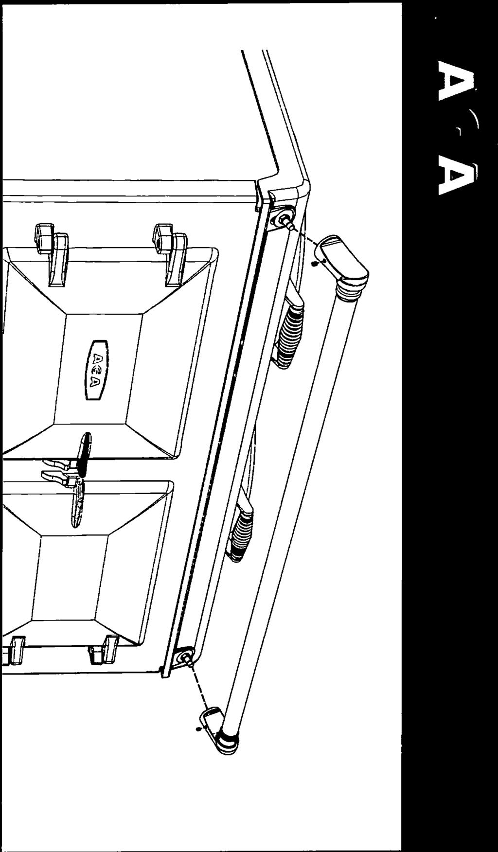
12 HOTCUPBOARD INSTALLATION NOTE: The AGA TC5 hotcupboard should arrive with the top plate in a jacked up position. This is to allow the complete appliance to be slid onto its plinth when alongside the AGA TC3 without the top plate clashing. The hotcupboard top plate should then be wound down to its correct height once the appliance is in its final position. 1. Detach hotcupboard from the plinth by removing two screws and tongue bracket from plinth (See Fig. 6). Slide hotcupboard forwards and away from rear fixing bracket (See Fig. 7). Fig. 6 DESN Fig. 7 DESN
.")
13 2. Position the plinth alongside the AGA Total Control leaving no gap between the two plinths (See Fig. 8). Check with a spirit level that the plinth level is correct, and also check height differential between the hotcupboard plinth and Total Control plinth is correct 7 /16 (11mm). If necessary, use shims in each corner to level the plinth. HOTCUPBOARD PLINTH BASE 7 +1 /16 (11mm) - 0 HEIGHT DIFFERENTIAL Fig. 8 DESN Attach hotcupboard plinth to the AGA Total Control plinth using M6 screws and washers provided (See Fig. 9). Attach locking screw and jacking screw into plinth. Make sure at this stage that the jacking screw does not protrude beyond outer face of plinth. Ensure locking screw is located into AGA TC3 plinth but not fully tightened. A gap of approximately 3mm should be present between the plinths apart from at the very front where the hotcupboard spacer plate should be touching the AGA TC3 plinth, Fig. 9 DESN
14 4. Run a straight edge along the front of the AGA Total Control plinth, to ensure the front face of both plinths sit squarely against the straight edge. (See Fig. 10) When satisfied both plinths sit squarely, jacking screws can be tightened until they just make contact with the AGA Total Control plinth and locking screws can now be tightened. USE STRAIGHT EDGE ACROSS BOTH PLINTHS TO ENSURE PLINTHS ARE ALIGNED SQUARELY Fig. 10 DESN Front jointing bracket can now be hooked into place over the two pot magnets. This will latch the two plinths together. (See Fig. 11) HOOK FRONT JOINTING BRACKET INTO PLACE TO LOCK TWO PLINTHS TOGETHER Fig. 11 DESN
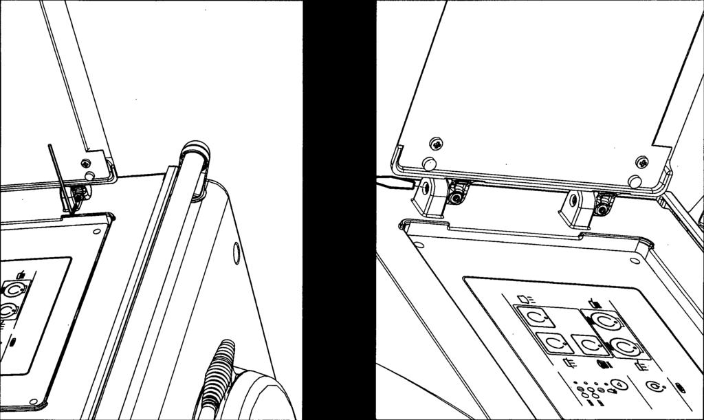
15 6. Slide hotcupboard onto plinth until rear tongue bracket engages fully into rear of base slot, (See Fig. 12). Ensure the appliance is aligned squarely with the plinth then proceed to engage the front tongue bracket into the slot on the underside of the base plate. Once satisfied that the front tongue bracket is engaged fully lock it into place by tightening the two M6 screws fully. Fig. 12 DESN The hotcupboard top plate is set 13 /64 (5mm) higher than the AGA Total Control top plate. This is to prevent damage to the enamel during installation. Lower the top plate using the adjusters (See Figs. 13 and 14). Fig. 13 DESN
16 8. Using the stay rod nut adjusting tool, carefully lower the top plate adjusting nuts until the top plates sits at the required height, making sure that the top sits level and matches the height of the AGA TC3. (See Fig. 14). Fig. 14 DESN Slide the complete handrail over the left hand, right hand and centre fixing studs. Once the assembly has been fitted to the AGA appliance, fit the handrail endcaps (ensuring the handrail is evenly spaced at each end). The endcaps should be carefully pushed into place until they sit flush with the outside face of each bracket. The handrail can now be locked into place using the grub screws on the underside of the handrail brackets. Finally fit plinth facia onto magnets positioned on plinth, ensuring the facia sits squarely and centrally. Fig. 15 DESN
17 HANDRAIL CONNECTION - AGA TC3 Fig. 16 DESN Handrail brackets. endcaps and handrails require assembly. Locate endcaps onto handrail, place brackets over endcaps and then slide complete assembly onto locating studs. Once assembly is correctly located, lock into position with grub screws (located on underside of handrail). 17
18 MAINS CORD AND WIRING DIAGRAM - AGA TC3 Fig
19 WIRING DIAGRAM - AGA TC5 (HOTCUPBOARD OPTION) CAUTION: LABEL ALL WIRES PRIOR TO DISCONNECTION, WHEN SERVICING CONTROLS WIRING ERRORS CAN CAUSE IMPROPER AND DANGEROUS OPERATION. VERIFY PROPER OPERATION AFTER SERVICING COLOUR KEYS/COLLEURS BR - BROWN/MARRON BL - BLUE/BLEU GR - GREEN/VERT OR - ORANGE/ORANGE BK - BLACK/NOIR ATTENTION: ETIQUETEZ TOUS LES CABLES AVANT DE LES DEBRANCHER LORS DE LES BRANCHER LORS DE L ENTRETIEN DES COMMANDES. DES ERREURS DE CABLAGE PEUVENT ENTRAINER UN FONCTIONNEMENT INCORRECT ET DANGEREUX. VERIFIEZ QUE L APPAREIL FONCTIONNE CORRECTEMENT APRES L ENTRETIEN. Fig
20 INSTRUCTIONS Hand this Installation Guide to the user for retention and instruct in the safe operation of the appliance. Also advise the user that, for continued efficient and safe operation of the appliance, servicing is carried out at intervals recommended by the AGA distributor. 20
21 21
22 22
23 23
24 For further advice or information contact your local AGA Specialist With AGA s policy of continuous product improvement, the Company reserves the right to change specifications and make modifications to the appliance described and illustrated at any time US Office: AGA MARVEL 1260 E Van Deinse St. Greenville, MI

25

26
AGA TOTAL CONTROL. Model No s: TC3 & TC5 (ROOM VENT OPTION)
") AGA TOTAL CONTROL Model No s: TC3 & TC5 (ROOM VENT OPTION) Installation Guide REMEMBER: when replacing a part on this appliance, use only spare parts that you can be assured conform to the safety and performance
AGA TOTAL CONTROL Model No s: TC3 & TC5 (ROOM VENT OPTION) Installation Guide REMEMBER: when replacing a part on this appliance, use only spare parts that you can be assured conform to the safety and performance
AGA TOTAL CONTROL. Model No. - TC3
 AGA TOTAL CONTROL Model No. - TC3 Installation Guide REMEMBER: when replacing a part on this appliance, use only replacement parts that you can be assured conform to the safety and performance specification
AGA DUAL CONTROL Model No s: DC3 & DC5. (Includes External Vent & Room Vent Option)
") AGA DUAL CONTROL Model No s: DC3 & DC5 (Includes External Vent & Room Vent Option) Installation Guide REMEMBER: when replacing a part on this appliance, use only spare parts that you can be assured conform
AGA DUAL CONTROL Model No s: DC3 & DC5 (Includes External Vent & Room Vent Option) Installation Guide REMEMBER: when replacing a part on this appliance, use only spare parts that you can be assured conform
TC MODULE (FFD) (with Gas Hob)
 (with Gas Hob)") TC MODULE (FFD) (with Gas Hob) Installation Instructions REMEMBER: when replacing a part on this appliance, use only spare parts that you can be assured conform to the safety and performance specification
TC MODULE (FFD) (with Gas Hob) Installation Instructions REMEMBER: when replacing a part on this appliance, use only spare parts that you can be assured conform to the safety and performance specification
Installation Instructions
 ELECTRIC MODULE Installation Instructions Remember, when replacing a part on this appliance, use only spare parts that you can be assured conform to the safety and performance specification that we require.
Installation Instructions 30 French Door Built-in Wall Ovens
 Installation Instructions 30 French Door Built-in Wall Ovens Questions? Call 1.800.GE.CARES (1.800.432.2737) or visit www.geappliances.com In Canada, call 1.800.561.3344 or visit www.geappliances.ca DESIGN
AGA ELECTRIC RANGE (EC LM - 2 OVEN & EE LM - 4 OVEN) - OWNERS MANUAL
 - OWNERS MANUAL") AGA ELECTRIC RANGE (EC LM - 2 OVEN & EE LM - 4 OVEN) - OWNERS MANUAL Comprising Installation & Users Instructions Remember, when replacing a part on this appliance, use only spare parts that you can be
AGA ELECTRIC RANGE (EC LM - 2 OVEN & EE LM - 4 OVEN) - OWNERS MANUAL Comprising Installation & Users Instructions Remember, when replacing a part on this appliance, use only spare parts that you can be
GE Monogram. Installation. Instructions. Stainless Steel Bottom Mount Built-In Refrigerators. Models ZICS36N RH ZICS36N LH
 GE Monogram Installation Instructions Stainless Steel Bottom Mount Built-In Refrigerators Models ZICS36N RH ZICS36N LH Before you begin - Read these instructions completely and carefully. IMPORTANT - Save
Installation Instructions. For the 18 Built-In Dishwasher and Front Color Panels
 Installation Instructions For the 18 Built-In Dishwasher and Front Color Panels Printed in USA 154232102 Before You Begin DO NOT INSTALL DISHWASHER UNTIL YOU HAVE READ ALL INSTRUCTIONS. FOR YOUR SAFETY,
INSTALLATION INSTRUCTIONS
 INSTALLATION INSTRUCTIONS BUILT-IN BOTTOM MOUNT REFRIGERATOR/FREEZER DBRTGK72SS-GRILLE KIT (FOR designer SERIES ONLY) VIKING RANGE CORPORATION 111 Front Street Greenwood, Mississippi (MS) 38930 USA (662)
INSTALLATION GUIDE NZ AU GB IE
 COMPANION PRODUCTS Coffee Maker EB60 Steam Oven OS60 Microwave Oven OM60 models INSTALLATION GUIDE NZ AU GB IE CONTENTS Coffee maker 13 1 Safety and warnings 1 2 Parts supplied 2 3 Prior to installation
Some models are supplied with a protective film on steel and aluminium parts. This film must be removed before installing/using the appliance.
 ELECTRIC RANGE for residential use only R Models: VEFSEE365D.. INSTALLATION INSTRUCTIONS IMPORTANT - PLEASE READ AND FOLLOW Before beginning, please read these instructions completely and carefully. Do
GAS COOKTOP INSTALLATION INSTRUCTIONS
 INSTALLATION AND SERVICE MUST BE PERFORMED BY A QUALIFIED INSTALLER. IMPORTANT: SAVE FOR LOCAL ELECTRICAL INSPECTOR'S USE. READ AND SAVE THESE INSTRUCTIONS FOR FUTURE REFERENCE. WARNING If the information
2 PREPARE THE OPENING
 Installation Instructions 27 & 30 Electric Built-In Wall Ovens Questions? Call 1.800.GE.CARES (1.800.432.2737) or visit www.geappliances.com In Canada, call 1.800.561.3344 or visit www.geappliances.ca
Installation Instructions
 Installation Instructions 30 Electric - Radiant Excludes Down-Draft Models If you have questions, call 800.GE.CARES or visit our website at: GEAppliances.com. In Canada, call 800.561.3344 or visit our
ELECTRIC COOKTOP INSTALLATION INSTRUCTIONS
 INSTALLATION AND SERVICE MUST BE PERFORMED BY A QUALIFIED INSTALLER. IMPORTANT: SAVE FOR LOCAL ELECTRICAL INSPECTOR'S USE. READ AND SAVE THESE INSTRUCTIONS FOR FUTURE REFERENCE. U.S.A. WARNING FOR YOUR
Questions on Installation? Call: GECARES (US) or Visit our Web site at: (US) 4" DUCT CLAMPS (2) OR 4" SPRING CLAMPS (2)
 or Visit our Web site at: (US) 4 DUCT CLAMPS (2) OR 4 SPRING CLAMPS (2)") Installation Instructions Questions on Installation? Call: 1-800-GECARES (US) or Visit our Web site at: www.geappliances.com (US) Electric Dryer 49 37 BEFORE YOU BEGIN Read these instructions completely
Installation Instructions Questions on Installation? Call: 1-800-GECARES (US) or Visit our Web site at: www.geappliances.com (US) Electric Dryer 49 37 BEFORE YOU BEGIN Read these instructions completely
Installation Instructions
 Installation Instructions For the 18" Built-In Dishwasher Sears, Roebuck and Co. Sears Canada, Inc. Hoffman Estates, IL 60179 U.S.A. Toronto, Ontario, Canada M5B 2B8 154435201 Before You Begin DO NOT INSTALL
Installation Instructions
 Installation Instructions For Fully Integrated NoFrost Combined Refrigerator-Freezers HC 2060/2061 7082 485-00 Important PLEASE READ AND FOLLOW THESE INSTRUCTIONS These instructions contain Warning and
GE Monogram. Automatic. Icemaker. Installation Instructions. Models ZDI15 ZDIS15. monogram.com
 GE Monogram Automatic Icemaker Installation Instructions Models ZDI15 ZDIS15 monogram.com Before you begin Read these instructions completely and carefully. IMPORTANT - Save these instructions for local
ELECTRIC COOKTOP INSTALLATION INSTRUCTIONS
 INSTALLATION AND SERVICE MUST BE PERFORMED BY A QUALIFIED INSTALLER. IMPORTANT: SAVE FOR LOCAL ELECTRICAL INSPECTOR'S USE. READ AND SAVE THESE INSTRUCTIONS FOR FUTURE REFERENCE. WARNING FOR YOUR SAFETY:
Advantium TM. Built-In. Speedcook Ovens. Installation. Instructions
 Advantium TM Built-In Speedcook Ovens Installation Instructions SCB2000, SCB2001 ZSC2000, ZSC2001 Before you begin Read these instructions completely and carefully. IMPORTANT - Save these instructions
Installation Instructions
 Installation Instructions 30 Electric Cooktop JP346, JP356, PP9, PP93, PP94, PP945, PP950 If you have questions, call 800.GE.CARES or visit our website at: ge.com BEFORE YOU BEGIN Read these instructions
Installation Instructions
 Installation Instructions For Fully Integrated NoFrost Combined Refrigerator-Freezers HC 2062 HCB 2062 HC/HCB 20 7082 373-00 Important PLEASE READ AND FOLLOW THESE INSTRUCTIONS These instructions contain
Installation Instructions
 Installation Instructions Over the Range Microwave Oven BEFORE YOU BEGIN (Read these instructions completely and carefully.) IMPORTANT IMPORTANT Save these instructions for local inspector s use. Observe
GE Monogram. Installation. Instructions. Professional Ranges. 48" Natural Gas Models ZDP48N4G ZDP48N6R ZDP48N6D
 GE Monogram Installation Instructions Professional Ranges 48" Natural Gas Models ZDP48N4G ZDP48N6R ZDP48N6D 48" LP Gas Models ZDP48L4G ZDP48L6R ZDP48L6D 36" Natural Gas Models ZDP36N6 ZDP36N4R ZDP36N4D
Installation Instructions
 GE Consumer & Industrial Appliances Installation Instructions Junction Box Cover Within this user bag, you will find a junction box cover and a #10 hex head screw used to attach the junction box cover
INSTALLATION INSTRUCTIONS
 INSTALLATION INSTRUCTIONS PROFESSIONAL RANGE MODELS 48 ALL GAS, CONVECTION WITH SEALED BURNERS** 48 NATURAL GAS MODELS *TN531-7BW *TN531-7W **THESE MODELS ARE NOT FIELD CONVERITBLE FOR LP/PROPANE GAS.
Installation Instructions. Rayburn 300W Wood Burning Cooker
 BS EN 12815 Consumer Protection Act 1987 As responsible manufacturers, we take care to make sure that our products are designed and constructed to meet the required safety standards when properly installed
Helpful Tip: NOTE:
 Grounded electrical supply required. Do not run drain lines, water lines or electrical wiring where they can interfere with or contact dishwasher motor or legs. The location where the dishwasher will be
INSTALLATION INSTRUCTIONS
 INSTALLATION INSTRUCTIONS PROFESSIONAL RANGE MODELS 48 ALL GAS, CONVECTION WITH SEALED BURNERS** 48 NATURAL GAS MODELS *TN531-7BW *TN531-7W **THESE MODELS ARE NOT FIELD CONVERITBLE FOR LP/PROPANE GAS.
Installation Instructions
 Installation Instructions 30 Electric Cooktop JP340, JP350, JP930, JP93, JP938, JP939 If you have questions, call 800.GE.CARES or visit our website at: www.geappliances.com BEFORE YOU BEGIN Read these
Installation Instructions
 Installation Instructions If you have questions, call 800.626.2000 or visit our website at: www.monogram.com Automatic Icemaker ZDI15 ZDIS15 Design Guide with BEFORE YOU BEGIN Read these instructions completely
Questions? Call 800.GE.CARES ( ) or visit our Web site at: GEAppliances.com In Canada, call or visit
 or visit our Web site at: GEAppliances.com In Canada, call or visit") Installation Instructions Electric Dryer 01 Questions? Call 800.GE.CARES (800.432.2737) or visit our Web site at: GEAppliances.com In Canada, call 1.800.561.3344 or visit www.geappliances.ca BEFORE YOU
Installation Instructions Electric Dryer 01 Questions? Call 800.GE.CARES (800.432.2737) or visit our Web site at: GEAppliances.com In Canada, call 1.800.561.3344 or visit www.geappliances.ca BEFORE YOU
INSTALLATION INSTRUCTIONS
 INSTALLATION INSTRUCTIONS BUILT-IN BOTTOM MOUNT REFRIGERATOR/FREEZER BRTGK72SS-GRILLE KIT (FOR PROFESSIONAL SERIES ONLY) VIKING RANGE CORPORATION 111 Front Street Greenwood, Mississippi (MS) 38930 USA
Installation Instructions. Instructions de montage. Instrucciones de instalación HC
 Installation Instructions For Fully Integrated NoFrost Combined Refrigerator-Freezers Instructions de montage Pour le réfrigérateurs-congélateurs combinés NoFrost encastrés, pour une utilisation intégrée
Installation Instructions
 Installation Instructions Advantium 240V Built-In SpeedCook Ovens PSB2200 PSB2201 ZSC2200 ZSC2201 ZSC2202 49-40574-1 MFL06213302 02-08 JR Safety Information BEFORE YOU BEGIN Read these instructions completely
Installation Instructions
 Installation Instructions For Built-In NoFrost Combined Refrigerator-Freezers C 16 CI 16 7080 007-00 IMPORTANT PLEASE READ AND FOLLOW THESE INSTRUCTIONS These instructions contain Warning and Caution statements.
130"ElectricCooktop. nstructlons _,0, JP355, JP910, JP930, JP940, JP950. I Iinstallation. -&WARNING - This appliance must be properly grounded.
 I Iinstallation 130"ElectricCooktop nstructlons _,0, JP355, JP910, JP930, JP940, JP950 I r_ www.geappliances.com",,if you have questions, call 800.GE.CARES or visit our website at: I BEFORE YOU BEGIN MATERIALS
Installation Instructions
 Installation Instructions For Free Standing NoFrost Combined Refrigerator-Freezers CS 1660 7082 653-00 PLEASE READ AND FOLLOW THESE INSTRUCTIONS These instructions contain Warning and Caution statements.
Installation Instructions
 Installation Instructions KFN 9855 ide en - CA Installation, repair and maintenance work should be performed by a Miele authorized service technician in accordance with national and local safety regulations
INSTALLATION GUIDE NZ AU F
 BUILT-IN OVEN OB76SD & OB76DD models INSTALLATION GUIDE NZ AU 590586 F 08.17 1 SAFETY AND WARNINGS WARNING! Electrical shock hazard Before carrying out any work on the electrical section of the appliance,
Built-In Dishwasher. Installation Instructions. BEFORE YOU BEGIN Read these instructions completely and carefully. IMPORTANT The dishwasher MUST be
 Installation Instructions Built-In Dishwasher If you have questions, call 800.GE.CARES (800.432.2737) or visit our website at: www.ge.com BEFORE YOU BEGIN Read these instructions completely and carefully.
Installation Instructions
 Installation Instructions For Fully Integrated NoFrost Combined Refrigerator-Freezers HCB 1560/1561 7084 429-00 Important Please read and follow these instructions These instructions contain Danger, Warning
Installation Instructions
 Installation Instructions Electric Drop-In Range JDS28, JDP39 Questions? Call 800.GE.CARES (800.432.2737) or Visit our Website at: ge.com BEFORE YOU BEGIN Read these instructions carefully and completely.
Installation Instructions for Models: HES232U, HES236UHES246U, HES247U, HES245U, HES242U, HES256U, HES255U, HES252U
 Freestanding Electric Range Household Appliances 2U Installation Instructions for Models: HES232U, HES236UHES246U, HES247U, HES245U, HES242U, HES256U, HES255U, HES252U PLEASE READ ENTIRE INSTRUCTIONS BEFORE
Installation Instructions Wall Ovens
 Installation Instructions Wall Ovens TESTED IN ACCORDANCE WITH THE LATEST EDITION OF UL858 STANDARD FOR HOUSEHOLD ELECTRIC COOKING APPLIANCES. IMPORTANT 1. Before beginning installation, please thoroughly
Downdraft Ventilation
 INSTALLATION GUIDE Downdraft Ventilation Contents Wolf Downdraft Ventilation...................... 3 Installation Considerations...................... 4 Downdraft Specifications.......................
Installation Instructions
 Installation Instructions Built-In Dishwasher If you have questions, call 800-GECARES or visit our website at: www.geappliances.com BEFORE YOU BEGIN Read these instructions completely and carefully. IMPORTANT
Installation Instructions If you have questions, call 800-GE-CARES or visit our website at:
 Installation Instructions If you have questions, call 800-GE-CARES or visit our website at: www.monogram.com 36" Stainless Steel Gas Cooktops Natural Gas Model: ZGU375NS LP Gas Model ZGU375LS Monogram.
A PROUD HERITAGE OF EXPERIENCE & QUALITY DISHWASHER BR-DWSH01-S
 A PROUD HERITAGE OF EXPERIENCE & QUALITY DISHWASHER BR-DWSH01-S, 1 6 7 $ / / $ 7, 2 1, 1 6 7 5 8 & 7, 2 1 6 W W W. V I N O T E M P. C O M Installation Instructions Dishwasher BEFORE YOU BEGIN Read these
GE Monogram. Installation. Instructions. Component Cooktop System. Models ZEW145V ZGW124EN3 ZGW125EN3 ZEW155N ZEW166Y ZEW176Y
 GE Monogram Installation Instructions Component Cooktop System Models ZEW145V ZGW124EN3 ZGW125EN3 ZEW155N ZEW166Y ZEW176Y Before you begin Read these instructions completely and carefully. IMPORTANT: Save
ELECTRIC WALL OVEN INSTALLATION INSTRUCTIONS
 INSTALLATION AND SERVICE MUST BE PERFORMED BY A QUALIFIED INSTALLER. IMPORTANT: SAVE FOR LOCAL ELECTRICAL INSPECTOR'S USE. READ AND SAVE THESE INSTRUCTIONS FOR FUTURE REFERENCE. FOR YOUR SAFETY: Do not
Installation Instructions
 Installation Instructions Downdraft Vent Systems PVB94 PVB98 ZVB30 ZVB36 31-10728-8 11-14 GE 1 Safety Information If you have questions, call 800.GE.CARES or visit our website at: GEAppliances.com BEFORE
Installation Instructions
 GE Consumer & Industrial Appliances Installation Instructions Junction Box Cover Within this user bag, you will find a junction box cover and a #10 hex head screw used to attach the junction box cover
I NDUCTION C OOKTOP INSTALLATION INSTRUCTIONS
 I NDUCTION C OOKTOP INSTALLATION INSTRUCTIONS CONTACT INFORMATION Wolf Customer Service: 800-332-9513 Website: wolfappliance.com As you follow these instructions, you will notice WARNING and CAUTION symbols.
GE Monogram. Installation. Instructions. Professional Ranges. 48" Natural Gas Models ZDP48N4GWSS ZDP48N6RWSS ZDP48N6DWSS
 GE Monogram Installation Instructions Professional Ranges 48" Natural Gas Models ZDP48N4GWSS ZDP48N6RWSS ZDP48N6DWSS 48" LP Gas Models ZDP48L4GWSS ZDP48L6RWSS ZDP48L6DWSS 36" Natural Gas Models ZDP36N6WSS
136"ElectricCooktop. nstructlons. I Iinstallation. -&WARNING - This appliance must be properly grounded.
 nstructlons I Iinstallation 136"ElectricCooktop I =_ www.g If you have EAp plia questions, nces.co m" call 800.GE.CARES or visit our website at: BEFORE YOU BEGIN MATERIALS YOU WILL NEED Read these instructions
Installation Instructions
 Instructions For Fully Integrated NoFrost Combined Refrigerator-Freezers HC 1540/1541 7084 433-00 Important Please read and follow these instructions These instructions contain Danger, Warning and Caution
INSTALLATION INSTRUCTIONS
 INSTALLATION INSTRUCTIONS PROFESSIONAL RANGE MODELS 24 ALL GAS, CONVECTION WITH OPEN BURNERS** 24 NATURAL GAS MODEL *TN480-7BW **THESE MODELS ARE FIELD CONVERITBLE FOR LP/PROPANE GAS.** 24 LP/PROPANE GAS
Questions? Call 800.GE.CARES ( ) or visit our Web site at: GEAppliances.com In Canada, call or visit
 or visit our Web site at: GEAppliances.com In Canada, call or visit") Installation Instructions Electric Dryer 01 Questions? Call 800.GE.CARES (800.432.2737) or visit our Web site at: GEAppliances.com In Canada, call 1.800.561.3344 or visit www.geappliances.ca BEFORE YOU
Installation Instructions Electric Dryer 01 Questions? Call 800.GE.CARES (800.432.2737) or visit our Web site at: GEAppliances.com In Canada, call 1.800.561.3344 or visit www.geappliances.ca BEFORE YOU
Viking Installation Guide
 Viking Installation Guide Viking Range Corporation 111 Front Street Greenwood, Mississippi 38930 USA (662) 455-1200 For product information, call 1-888-VIKING1 (845-4641) or visit the Viking Web site at
High Power Range Hood
 High Power Range Hood Pictured Model: CW500 Installation and Operating Instructions Please read all instructions before installing and operating. All wiring and installation must be in accordance with
INSTALLATION GUIDE NZ AU GB IE A
 BUILT IN OVEN OB90 models INSTALLATION GUIDE NZ AU GB IE 591672A 09.18 1 SAFETY AND WARNINGS WARNING! Electrical shock hazard Always disconnect the appliance from the mains power supply before carrying
INSTALLATION INSTRUCTIONS
 INSTALLATION INSTRUCTIONS BUILT-IN FULL HEIGHT WINE CELLAR (VCWB300 PROFESSIONAL MODEL) Retain for Future Reference VIKING RANGE CORPORATION 111 Front Street Greenwood, Mississippi 38930 USA (662) 455-1200
GE Monogram. Installation. Instructions. Professional Gas Cooktops 48" Natural Gas Models ZGU48N4GWSS ZGU48N6RWSS ZGU48N6DWSS
 GE Monogram Installation Instructions Professional Gas Cooktops 48" Natural Gas Models ZGU48N4GWSS ZGU48N6RWSS ZGU48N6DWSS 48" LP Gas Models ZGU48L4GWSS ZGU48L6RWSS ZGU48L6DWSS 36" Natural Gas Models ZGU36N6YSS
INSTALLATION INSTRUCTIONS
 INSTALLATION INSTRUCTIONS PROFESSIONAL COOKTOP MODELS 48 GAS COOKTOP WITH SEALED BURNERS** 48 NATURAL GAS MODEL *TN047-7 **THIS MODEL IS NOT FIELD CONVERITBLE FOR LP/PROPANE GAS. IT MUST BE ORDERED FROM
3DIR52XXD Series Fan. Owner s Guide and Installation Manual. UL Model NO. : 3DIR52XXD
 Owner s Guide and Installation Manual 3DIR52XXD Series Fan UL Model NO. : 3DIR52XXD Attach sales receipt to this card and retain as your proof of purchase DATE OF PURCHASE: MODEL NUMBER: RETAILER NAME:
Installation Instructions
 Installation Instructions Above the Cooktop Microwave Oven JVM60 and JVM65 Questions? Call -800-56- or Visit our Website at: GEAppliances.ca BEFORE YOU BEGIN Read these instructions completely and carefully.
Installation Instructions
 Installation Instructions Built-In Dishwasher If you have questions, call 800-944-9400(US),800-245-8352(Canada)or visit our website at: www.frigidaire.com BEFORE YOU BEGIN Read these instructions completely
Table of Contents. Important Safety Instructions. WARNING: If the instructions contained in this manual are not followed
 Table of Contents 1 Installation 6 1.1 General installation instructions 6 1.2 Electrical requirements 7 1.3 Electrical connection 8 1.4 Cable replacement 10 1.5 Positioning 10 EN Important Safety Instructions
Dryer. User manual DV22K6800** DV22K A-00_EN (US)_ indd :15:41
_ indd :15:41") Dryer User manual DV22K6800** DV22K6800-03650A-00_EN (US)_151211.indd 1 2015-12-11 7:15:41 Before installation Read through the following instructions before installing the dryer, and keep this manual
Dryer User manual DV22K6800** DV22K6800-03650A-00_EN (US)_151211.indd 1 2015-12-11 7:15:41 Before installation Read through the following instructions before installing the dryer, and keep this manual
Installation Instructions
 Installation Instructions Before you begin... 2 Location... 2 Recommended grounding instructions... 2 Electrical requirements... 2 Exhaust requirements... 3 Water supply and drain requirements... 3 Please
Installation Instructions Dual Fuel Ranges
 Installation Instructions Dual Fuel Ranges E30DF74EPS E36DF76EPS E48DF76EPS 5995447082 2 Safety IMPORTANT SAFETY INSTRUCTIONS Safety Precautions Do not attempt to install or operate your unit until you
INSTALLATION INSTRUCTIONS ELECTRIC DRYER
 INSTALLATION INSTRUCTIONS ELECTRIC DRYER Table of Contents... 2 IMPORTANT: Save for local electrical inspector s use. 3397627C DRYER SAFETY... 2 INSTALLATION INSTRUCTIONS... 4 Tools and Parts... 4 Location
Installation. Built-in Full Height Wine Cellar VCWB301
 Installation Built-in Full Height Wine Cellar VCWB301 Table of Contents Warnings & Important Information _ 3 Dimensions _ 5 Specifications _ 6 Cutout Dimensions 7 Cabinet Information _ 8 Cabinet Information
Installation Instructions
 WARNING! INSTALLATION SAFETY INSTRUCTIONS Read these instructions completely and carefully. Improper installation, adjustment, alteration, service or maintenance can cause injury or property damage. Refer
Installation Instructions
 Installation Instructions For Fully Integrated NoFrost Combined Refrigerator-Freezers HC 2060/2061 HCB 2060/2061 7084 349-00 Important Please Read and Follow these Instructions These instructions contain
Installation Instructions
 Installation Instructions For Fully Integrated NoFrost Combined Refrigerator-Freezers HCB 1560/1561 HC 1550 7084 327-00 Important Please Read and Follow these Instructions These instructions contain Danger,
Installation Instructions
 Installation Instructions Full Size Tumble Action Washers Before beginning installation, carefully read these instructions. This will simplify the installation and ensure the washer is installed correctly
INSTALLATION GUIDE Induction Cooktops
 INSTALLATION GUIDE Induction Cooktops Contents Wolf Induction Cooktops....................... 3 Induction Cooktop Specifications................ 4 Induction Cooktop Installation.................. 12 Service
Viking Installation Guide
 Viking Installation Guide Viking Range, LLC 111 Front Street Greenwood, Mississippi 38930 USA (662) 455-1200 For product information, call 1-888-(845-4641) or visit the Viking Web site at vikingrange.com
Installation Instructions
 Installation Instructions Over the Range Microwave Oven PVM88 Questions? Call -800-56-44 or Visit our Website at: GEAppliances.ca BEFORE YOU BEGIN Read these instructions completely and carefully. IMPORTANT
INSTALLATION AND OPERATION INSTRUCTIONS FOR BI-DEEP UNITS
 INSTALLATION AND OPERATION INSTRUCTIONS FOR BI-DEEP UNITS BI-40-DEEP BI-50-DEEP BI-60-DEEP BI-72-DEEP BI-88-DEEP SAFETY INFORMATION WARNING If the information in these instructions are not followed exactly,
LIMITED LIFETIME WARRANTY
 LIMITED LIFETIME WARRANTY Model No.: F0023 / F0024 aireryder ORIGINAL CEILING FAN LIMITED LIFETIME WARRANTY The limited lifetime warranty covers this ceiling fan, for residential use by the original purchaser,
Microwave Oven. IMPORTANT SAFETY INSTRUCTION Never operate the oven when it is empty or without the glass turntable.
 Microwave Oven Introduction Installation Manual IMPORTANT SAFETY INSTRUCTION Never operate the oven when it is empty or without the glass turntable. Your Over-the-Range microwave oven comes complete with
Installation Instructions
 Installation Instructions Gas & Electric Dryer Before beginning installation, carefully read these instructions. This will simplify the installation and ensure the dryer is installed correctly and safely.
Top Control Dishwasher
 INSTALLATION GUIDE Top Control Dishwasher NS-DWH2BS8/NS-DWH2SS8/NS-DWR2BS8/NS-DWR2WH8/NS-DWR2SS8 Before using your new product, please read these instructions to prevent any damage. Contents Introduction......................................................................................................
Dishwasher Installation Instructions DW 24XT/DW 24XV
 Dishwasher Installation Instructions DW 24XT/DW 24XV Installation Instructions Dishwasher BEFORE YOU BEGIN Read these instructions completely and carefully. IMPORTANT Observe all governing codes and ordinances.
Installation instructions
 Installation instructions Ceramic hobs KM 6200 / 6202 / 6203 KM 6204 / 6206 / 6207 / 6208 KM 6212 / 6213 / 6215 / 6216 To avoid the risk of accidents or en-gb damage to the appliance it is essential to
A PROUD HERITAGE OF EXPERIENCE & QUALITY DISHWASHER BR- DWSH01- S
 A PROUD HERITAGE OF EXPERIENCE & QUALITY DISHWASHER BR- DWSH01- S W W W. V I N O T E M P. C O M Installation Instructions Dishwasher BEFORE YOU BEGIN Read these instructions completely and carefully. IMPORTANT
FRANKE DESIGNER GAS COOKTOP 90CM
 page 1 of 7 510 880 45 480 Min 50 860 Min 600 SPECIFICATIONS Recommended use Material Colour availability Weight Dimensions Voltage Domestic Stainless Steel Stainless Steel 18.2kg 880 x 510 x 45mm 220-240V
Over-the-Range Microwave Oven Installation Instructions MVH130* MVH230* MVH330*
 Over-the-Range Microwave Oven Installation Instructions MVH130* MVH230* MVH330* * Additional alphanumeric characters representing other models in the series may follow each model number. Keep these instructions
AGA 13 AMP RETRO-FIT WITH AIMS
 AGA 13 AMP RETRO-FIT WITH AIMS (OIL TO ELECTRIC) FITTING INSTRUCTIONS LEAVE WITH CUSTOMER For use in GB and IE 04/14 EINS 515736 OIL TO ELECTRIC CONVERSION INSTRUCTIONS l ISOLATE ELECTRIC SUPPLY, OIL SUPPLY
RS Chimney Fan For Gas & Oil Applications. Installation & Operating Manual USA CAN
 Installation & Operating Manual 3000270 10.01 USA CAN RS Chimney Fan For Gas & Oil Applications 1200 Northmeadow Parkway, STE 180 Roswell, GA 30076 (770) 587-3238 (800) 255-2923 Fax (770) 587-4731 info@exhausto.com
136"ElectricCooktop. nstructlons _,00, JP961, JP968, JP969, ZEU769. I Iinstallation. -&WARNING - This appliance must be properly grounded.
 I Iinstallation 136"ElectricCooktop nstructlons _,00, JP961, JP968, JP969, ZEU769 I "?-I www.g "If you have EAp plia questions, nces.co m" call 800.GE.CARES or visit our website at: BEFORE YOU BEGIN MATERIALS
INSTALLATION INSTRUCTIONS
 INSTALLATION INSTRUCTIONS BUILT-IN FULL HEIGHT WINE CELLAR Retain for Future Reference VIKING RANGE CORPORATION 111 Front Street Greenwood, Mississippi 38930 USA (662) 455-1200 IMPORTANT - PLEASE READ
Installation Manual. Electric Range LSC5622W / LSB5611S / LST5601S / LSC5633W LSC5674W / LSC5683W / LSB5682S / LST5651S. Website:
 Website:http://ca.lge.com Installation Manual Electric Range LSC5622W / LSB5611S / LST5601S / LSC5633W LSC5674W / LSC5683W / LSB5682S / LST5651S Please read these instructions thoroughly before installing
Installation Instructions
 Installation Instructions Self-Cleaning Radiant Electric Drop-In Range JDP47, JD968, JD900 If you have questions, call 1.800.GE.CARES or visit our website at: ge.com Before You Begin Read these instructions
Ilnstallat!on. nstruct=ons. Before You Begin. Parts Included. Tools Needed. Built-In Wall Oven with Microwave ATTENTION INSTALLER
 Ilnstallat!on nstruct=ons Built-In Wall Oven with Microwave 27" (68.6 cm) model JKP90 30" (76.2 cm) models JTP90, PT970 If you have questions, call 1.800.GE.CARES or visit our website at: ge.com Before