Dehydrators and Filters
|
|
|
- Ferdinand Short
- 5 years ago
- Views:
Transcription

1 Dehydrators and Filters
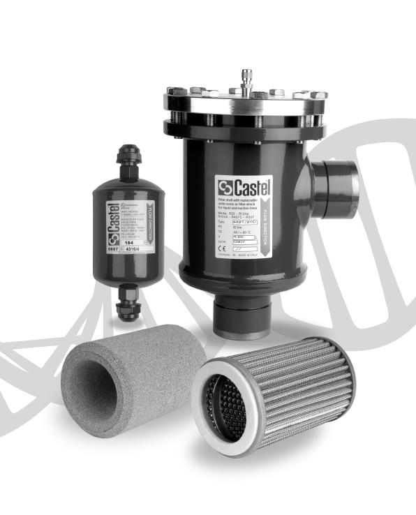
2 DEHYDRATION OF REFRIGERANTS Among contaminating agents causing serious damages to refrigerating systems, moisture plays a major role. Its presence, even possible in the refrigerating system, is due to many factors: inadequate or insufficiently prolonged vacuum before refrigerant charging; oil used for topping up remained exposed to air humidity; refrigerant used for subsequent additions contained in non dried vessels; sealing defects especially in systems not designed for operation at low temperatures. High temperatures combined with humidity give rise to complex phenomena enhancing acid formation both in lubricating oil and refrigerant. Oil organic acids react with metal and favor the formation of sludge, which are viscous clots consisting of insoluble metal salts and large molecules of polymerized oil. Sludge affects the lubrication of the moving elements of the compressor, can clog valves and filters and cause serious damages. Acids, especially hydrofluoric acid, produced by the hydrolysis of the fluorinated refrigerant (in compressors iron and aluminum act as catalysts) are particularly corrosive. Acids etch metal surfaces with the consequent formation of crystal salts, which stick to surfaces and affect the total heat exchange coefficient in the condenser and in the evaporator. In the sealed and semi-sealed groups, these salts damage the windings of electric motors as in these groups cold gas cools windings through direct contact. On the other hand, water solubility in refrigerants in a liquid phase, is quite reduced, especially at low temperatures. As a consequence, when in the system water exceeds the very low limits of solubility admitted at low temperature, excess water turns into ice, and blocks expansion valves and capillaries either partially or totally. Consequently, refrigerating plants must be equipped with a filter drier on the liquid line and types available on the market are essentially two: molecular sieve driers and solid core driers. In molecular sieve driers, with a charge constituted by non-agglomerated products, the dehydrating mass is pressed in between two fine steel mesh disks, or two filtering disks of various material, kept in place by a spring. In solid core driers, dehydrating and deacidifying products with binders constitute the block. Water adsorption combines with the neutralization of acids that may be present in the refrigerant, and with a strong filtering action. Castel have planned either its production lines of hermetic driers on this second solution that avoid any risk of abrasion of the charge and consequently the making of powder and permit to put the filter in any position inside the refrigerating system. It is always advisable to install a moisture indicator downstream the filter, which will show the refrigerant moisture and, consequently, the degree of efficiency of the filter. The dehydrating capacity of Castel drier is relative to the charge of refrigerant and not to the refrigeration potential of the plant. As a matter of fact, for the same refrigerant potential and for the same type of refrigerant fluid, there can be different refrigerant charges according to the type, design and working conditions of the plant as well as to the shutter degree. The data shown in the following tables are deduced from the test results of the present Castel production. It is important to note in the case of a high oil level in the circuit (> 5%) the data shown in the tables will be reduced considerably. 84

3 ANTI-ACID SOLID CORE FILTER DRIERS WITH MOLECULAR SIEVES AND ACTIVATED ALUMINA SERIES 42 Approved by Underwriters Laboratories Inc. SOLID CORE FILTER DRIERS WITH 100% MOLECULAR SIEVES SERIES 43 Approved by Underwriters Laboratories Inc. APPLICATIONS The filters, shown in this chapter, are classified Pressure vessels in the sense of the Pressure Equipment Directive 94/23/EC, Article 1, Section and are subject of Article 3, Section 1.1 of the same Directive. They are designed for installation on commercial refrigerating systems and on civil and industrial conditioning plants, which use refrigerant fluids proper to the Group II (as defined in Article 9, Section 2.2 of Directive 97/23/EC and referred to in Directive 67/548/EEC). Filters series 42 and series 43 have been developed for specific installations on refrigerating systems using HFC refrigerant fluids, particularly,,, and mixed with polyolester lubricants. In spite of this, the new block may be successfully used also in refrigerating systems using the old CFC or HCFC refrigerant fluids, mixed with mineral lubricants. activated alumina, and a special binding agent in appropriate proportions. The choice of blend, molecular sieves activated alumina, gives to the block a very high capacity of acid adsorption also maintaining very good dehydrating characteristics. The presence of a controlled and defined percentage of activated alumina, lower than the maximum value recommended by ASERCOM, keeps unchanged the original concentration of additives in the polyolester lubricant. The blocks in the filters series 43 are molded from a blend of dehydrating charge, totally made of 3 Å molecular sieves, and a special binding agent in appropriate proportions. The choice of the 3 Å molecular sieves, as sole dehydrating material, gives to the block a superlative capacity of water adsorption also CONSTRUCTION The filter is completely manufactured in steel, either with nickel-plated Flare threaded connections. The product range also includes types with copper plated solder connections, offering the possibility to solder the copper pipe inside the connections (ODS) or outside the connections, using a copper sleeve (ODM). On specific customers request, Castel is also able the supply them filters series 42 and 43 with: solder connections made of copper tube EN Cu-DHP ORFS (O-Ring Face Seal) threaded connections according to SAE J 1453 Standard. The blocks in the filters series 42 are molded from a blend of dehydrating charge, 80% of 3 Å molecular sieves and 20 % of 85

4 maintaining quite good deacidifying characteristics. The manufacturing process gives a considerable compacted ness and stoutness to both the products so that they are resistant to shocks and abrasions. The shape of the block is designed in order to offer the maximum possible surface area to the incoming fluid. The internal cavity is also positioned in such a way as to have a uniform wall thickness. As a result, the fluid encounters a constant strength at all points, flows linearly through the block, and ensures efficient dehydration and minimum charge loss. The block is chemically inert, not deliquescent, does not react with refrigerating fluids, and is capable of blocking oil by-products dragged into the circuit. Impurities accumulate in the ring between the metal shell and the block; this prevents filter clogging. EXAMPLE OF SELECTION System data: Refrigerant: Condensing temperature: + 50 [ C] Weight of refrigerant: 34 [kg] According to DIN 8949:2000, the adsorption capacity of the drier is given by: ( ) x 34 / = 34 g of H 2 O where: ppm. = moisture in the refrigerant entering the filter according to DIN 8949: ppm. = moisture in the refrigerant flowing out the filter according to DIN 8949:2000 Comparing the absorption capacity required with the values shown in table 3, drier mod.4341 should be selected, with a water absorption capacity of 40,5 g at 50 C. If the dehydrating capacity of products is expressed in water drops, it must be remembered that: 1g H 2 O = 20 water drops In this case and when a molecular sieve drier is selected, the following result is obtained: 34 x 20 = 680 water drops. If moisture exceeds the values specified in DIN 8949:2000, a drier with a higher adsorption capacity shall be selected. flow direction Solid core dehydrator 1 Spring 2 Block 3 Felt 4 Stainless steel mesh 86
5 TABLE 1a: General Characteristics of filters with high water capacity core (1). SAE flare connections International Reference Block Filtering Surface [cm 2 ] Nominal Volume [cm 3 ] Connections min. TS [ C] max. PS [bar] Risk Category according to PED 4303/ /2F (2) / / /2F (2) / / /2F (2) 4308/ /3F (2) 4308/4 43/2 43/ (3) Art /3F (2) /4 4 43/ / /4 4330/ / /5 4341/ / (1) 100% molecular sieves; (2) Male-female connections (Inlet female) (3) PS = 400 psig in compliance with the UL approval 87
6 TABLE 1b: General Characteristics of filters with high water capacity core (1). Solder connections International Reference Block Filtering Surface [cm 2 ] Nominal Volume [cm 3 ] [in.] ODS Connections [in.] ODM min. TS [ C] max. PS [bar] Risk Category according to PED 4303/2S 032S /2S 052S 4305/3S 053S /M10S /2S 082S 4308/3S 083S 4308/M10S /M12S /4S 084S 43/3S 3S 43/M10S 43/M12S Art /4S 43/5S 4330/3S 4S 5S 303S (2) 4330/4S 304S /5S 305S 4332/4S 4332/5S 304S 305S /5S 415S 4341/6S 4S /7S 417S 1.1/8" 4375/4S 754S 4375/5S 755S 4375/6S 756S I 4375/7S 757S 1.1/8" 4375/9S 759S 1.1/8" (1) 100% molecular sieves; (2) PS = 400 psig in compliance with the UL approval 88
7 TABLE 2a: General Characteristics of filters with antiacid core (1). SAE Flare connections International Reference Block Filtering Surface [cm 2 ] Nominal Volume [cm 3 ] Connections min. TS [ C] max. PS [bar] Risk Category according to PED 4203/ / / / / / / /2 2 42/3 42/ (2) Art / / / / /4 4232/ /5 4241/ (1) 80% molecular sieves + 20% activated alumina; (2) PS = 400 psig in compliance with the UL approval 89
8 TABLE 2b: General Characteristics of filters with antiacid core (1). Solder connections International reference Block Filtering Surface [cm 2 ] Nominal Volume [cm 3 ] [in.] ODS Connections [in.] ODM min. TS [ C] max. PS [bar] Risk Category according to PED 4203/2S 032S /2S 052S 4205/3S 053S /M10S /2S 082S 4208/3S 083S 4208/M10S /M12S /4S 084S 42/3S 42/M10S 42/M12S 3S _ (2) Art /4S 4S 42/5S 5S 4230/3S 303S 4230/4S 304S /5S 305S 4232/4S 4232/5S 304S 305S /2 4241/5S 415S 4241/6S 4S /7S 417S 1.1/8" 4275/4S 754S 4275/5S 755S 4275/6S 756S I 4275/7S 757S 1.1/8" 4275/9S 759S 1.1/8" (1) 80% molecular sieves + 20% activated alumina; (2) PS = 400 psig in compliance with the UL approval 90
9 91 (1) (2) See caption on page 92. TABLE 3: Refrigerant Flow Capacity and Water Capacity Refrigerant Flow Capacity, Pressure drop 0,07 bar (1) [kw] 4303/2 4303/2F 4303/2S 4303/3 4305/2 4305/2F 4305/2S 4305/3 4305/3S 4305/M10S 4308/2 4308/2F 4308/2S 4308/3 4308/3F 4308/3S 4308/M10S 4308/M12S 4308/4 4308/4S 43/2 43/3 43/3F 43/3S 43/M10S 43/M12S 43/4 43/4S 43/5 43/5S 4330/3 4330/3S 4330/4 4330/4S 4330/5 4330/5S 4332/4 4332/4S 4332/5 4332/5S 4341/5 4341/5S 4341/6 4341/6S 4341/7S 4375/4S 4375/5S 4375/6S 4375/7S 4375/9S 6,5 8,0 14,9 6,7 8,2 15,4 19,4 6,9 8,5 18,0 22,8 29,0 24,0 29,0 6,9 19,7 24,6 34,1 28,2 34,1 37,6 45,0 21,7 27,1 30,9 37,3 38,8 46,6 33,6 40,5 39,9 48,2 40,9 49,5 67,2 74,2 53,4 54,5 80,6 92,8 96,5 7,0 8,6,1 7,2 8,9,6 21,0 7,5 9,2 19,5 24,7 31,3 25,9 31,3 7,5 21,3 26,6 36,9 30,5 36,9 40,6 48,7 23,4 29,3 33,4 40,4 41,9 50,4 36,3 43,8 43,1 52,1 44,2 53,5 72,6 80,2 57,7 58,9 87,1 100,3 104,3 4,6 5,6 10,5 4,7 5,8 10,8 13,7 4,9 6,0 12,7,1 20,4,9 20,4 4,9 13,9 17,3 24,0 19,9 24,0 26,4 31,7 15,3 19,0 21,8 26,3 27,3 32,8 23,6 28,5 28,1 33,9 28,8 34,8 47,3 52,2 37,5 38,3 56,8 65,3 67,9 6,9 8,5,0 7,1 8,8,5 20,8 7,4 9,1 19,3 24,5 31,0 25,7 31,0 7,4 21,1 26,4 36,6 30,3 36,6 40,3 48,3 23,2 29,0 33,2 40,0 41,6 50,0 36,0 43,4 42,8 51,7 43,8 53,1 72,0 79,6 57,3 58,4 86,4 99,5 103,5 7,0 8,6,2 7,2 9,0,7 21,2 7,5 9,3 19,6 24,8 31,4 26,0 31,4 7,5 21,4 26,7 37,0 30,6 37,0 40,8 48,9 23,5 29,4 33,5 40,5 41,9 50,6 36,4 44,0 43,0 52,3 44,4 53,7 73,0 80,5 57,9 59,1 87,6 100,6 104,7 Water capacity at + 25 C (2) [g H 2 O] 4,1 7,3 12,7 25,1 50,2 45,4 61,4 122,8 3,8 6,7 11,6 22,9 45,8 41,4 56,1 112,2 4,2 7,4 13,0 25,6 51,2 46,4 62,8 125,6 3,4 6,0 10,4 20,5 41,0 37,2 50,3 100,6 3,7 6,5 11,3 22,3 44,6 40,5 54,7 109,4 Dehydratable Charge at + 25 C [kg refrigerant] 4,4 7,8 13,7 27,0 54,0 48,8 66,0 132,0 4,0 7,2 12,5 24,6 49,2 44,5 60,3 120,6 4,5 8,0 13,9 27,5 55,1 49,9 67,5 135,1 3,6 6,4 11,2 22,0 44,1 40,0 54,1 108,2 3,9 7,0 12,2 24,0 48,0 43,5 58,8 117,6 Water capacity at + 50 C (2) [g H 2 O] 3,5 6,3 10,9 21,6 43,2 39,1 53,0 106,0 3,0 5,3 9,3 18,4 36,8 33,2 45,0 90,0 3,9 6,9 12,0 23,8 47,6 43,1 58,3 1,6 2,7 4,8 8,4,5 33,0 29,9 40,5 81,0 2,9 5,2 9,1 18,0 36,0 32,6 44,1 88,2 Dehydratable Charge at + 50 C [kg refrigerant] 3,8 6,8 11,8 23,2 46,5 42,0 57,0 114,0 3,2 5,7 10,0 19,8 39,6 35,7 48,4 96,8 4,2 7,4 13,0 25,6 51,2 46,3 62,7 125,4 2,9 5,2 9,0 17,7 35,5 32,2 43,5 87,1 3,2 5,6 9,8 19,4 38,7 35,1 47,4 94,8
10 TABLE 4: Refrigerant Flow Capacity and Water Capacity Water capacity, Pressure drop 0,07 bar (1) [kw] Water capacity at + 25 C (2) [g H 2 O] Dehydratable Charge at + 25 C [kg refrigerant] Water capacity at + 50 C (2) [g H 2 O] Dehydratable Charge at + 50 C [kg refrigerant] 4203/2 6,5 7,0 4,6 6,9 7,0 4203/2S 8,0 8,6 5,6 8,5 8,6 3,5 3,2 3,6 2,9 3,1 3,8 3,4 3,9 3,1 3,4 3,0 2,6 3,3 2,3 2,5 3,3 2,8 3,6 2,5 2,7 4203/3 14,9,1 10,5,0,2 4205/2 6,7 7,2 4,7 7,1 7,2 4205/2S 4205/3 8,2 8,9 5,8 8,8 9,0 15,4,6 10,8,5,7 6,2 5,7 6,3 5,1 5,5 6,7 6,1 6,8 5,5 6,0 5,4 4,5 5,9 4,1 4,5 5,8 4,9 6,3 4,4 4,8 4205/3S 19,4 21,0 13,7 20,8 21,2 4208/2 6,9 7,5 4,9 7,4 7,5 4208/2S 8,5 9,2 6,0 9,1 9,3 4208/3 4208/3S 18,0 19,5 12,7 19,3 19,6 22,8 24,7,1 24,5 24,8 10,8 9,9 11,0 8,8 9,6 11,6 10,6 11,9 9,5 10,3 9,3 7,9 10,2 7,1 7,7 10,0 8,5 11,0 7,7 8,3 4208/4 24,0 25,9,9 25,7 26,0 4208/4S 29,0 31,3 20,4 31,0 31,4 42/2 6,9 7,5 4,9 7,4 7,5 42/3 19,7 21,3 13,9 21,1 21,4 42/3S 24,6 26,6 17,3 26,4 26,7 42/4 28,2 30,5 19,9 30,3 30,6 21,3 19,5 21,8 17,4 19,0 22,9 20,9 23,4 18,7 20,4 18,4 15,6 20,2 14,0 15,3 19,7,8 21,8 15,1,5 42/4S 34,1 36,9 24,0 36,6 37,0 42/5 37,6 40,6 26,4 40,3 40,8 42/5S 45,0 48,7 31,7 48,3 48,9 4230/3 21,7 23,4 15,3 23,2 23,5 4230/3S 27,1 29,3 19,0 29,0 29,4 4230/4 4230/4S 30,9 33,4 21,8 33,2 33,5 37,3 40,4 26,3 40,0 40,5 42,7 38,9 43,5 34,9 37,9 45,9 41,9 46,8 37,5 40,8 36,7 31,3 40,5 28,1 30,6 39,5 33,6 43,5 30,2 32,9 4230/5 38,8 41,9 27,3 41,6 41,9 4230/5S 46,6 50,4 32,8 50,0 50,6 4232/4 33,6 36,3 23,6 36,0 36,4 4232/4S 4232/5 40,5 43,8 28,5 43,4 44,0 39,9 43,1 28,1 42,8 43,0 38,6 35,2 39,4 31,6 34,4 41,5 37,8 42,4 34,0 37,0 33,2 28,2 36,6 25,4 27,7 35,7 30,3 39,4 27,3 29,8 4232/5S 48,2 52,1 33,9 51,7 52,3 4241/5 40,9 44,2 28,8 43,8 44,4 4241/5S 49,5 53,5 34,8 53,1 53,7 4241/6 4241/6S 67,2 72,6 47,3 72,0 73,0 52,2 47,7 53,4 42,8 46,5 56,1 51,3 57,4 46,0 50,0 45,1 38,3 49,6 34,4 37,5 48,4 41,1 53,3 37,0 40,3 4241/7S 74,2 80,2 52,2 79,6 80,5 4275/4S 53,4 57,7 37,5 57,3 57,9 4275/5S 54,5 58,9 38,3 58,4 59,1 4275/6S 80,6 87,1 56,8 86,4 87,6 104,4 95,4 106,8 85,5 93,0 112,2 102,5 114,8 91,9 100,0 90,1 76,5 99,1 68,9 75,0 96,9 82,3 106,6 74,0 80,6 4275/7S 92,8 100,3 65,3 99,5 100,6 4275/9S 96,5 104,3 67,9 103,5 104,7 (1) Maximum values of the refrigerant flow capacity at which the drier can be used when fluid dehydration is not the a major problem, provided that the original moisture is limited before the installation of the drier. The maximum refrigerant flow capacities are referred to a total pressure drop of 0,07 bar, inlet and outlet connections included, (according to ARI STANDARD 710:86 - with condensing temperature at +30 C and evaporating temperature at -15 C) (2) Water capacity values with are referred to the following conditions, fixed in ARI STANDARD 710:86: - Liquid temperatures: 25 C and 50 C - Equilibrium point dryness, EPD: 60 ppm Water capacity values with the other refrigerant fluids are referred to the following conditions, fixed in DIN 8949:2000 Standard: - Liquid temperatures: 25 C and 50 C - Equilibrium point dryness, EPD: 50 ppm 92
11 93 TABLE 5: Dimensions and Weights 4303/2 4303/2F 4303/2S 4303/3 4305/2 4305/2F 4305/2S 4305/3 4305/3S 4305/M10S 4308/2 4308/2F 4308/2S 4308/3 4308/3F 4308/3S 4308/M10S 4308/M12S 4308/4 4308/4S 43/2 43/3 43/3F 43/3S 43/M10S 43/M12S 43/4 43/4S 43/5 43/5S 4330/3 4330/3S 4330/4 4330/4S 4330/5 4330/5S 4332/4 4332/4S 4332/5 4332/5S 4341/5 4341/5S 4341/6 4341/6S 4341/7S 4375/4S 4375/5S 4375/6S 4375/7S 4375/9S 4203/2 4203/2S 4203/3 4205/2 4205/2S 4205/3 4205/3S 4208/2 4208/2S 4208/3 4208/3S 4208/4 4208/4S 42/2 42/3 42/3S 42/4 42/4S 42/5 42/5S 4230/3 4230/3S 4230/4 4230/4S 4230/5 4230/5S 4232/4 4232/4S 4232/5 4232/5S 4241/5 4241/5S 4241/6 4241/6S 4241/7S 4275/4S 4275/5S 4275/6S 4275/7S 4275/9S 1.1/8" SAE Flare [in.] D L ODS Connections Dimensions Weight [g] male connections male - female connections (female - in) solder connections

12 SOLID CORE FILTER DRIERS WITH SIGHT GLASS SERIES 41 CONSTRUCTION The filter series 41 is a liquid line filter drier with a sight glass directly brazed on its outlet side. This group reduces the amount of field brazing required and the potential risk for leaks. Moisture/liquid indicators ensure a fast and safe inspection of the conditions of the refrigerant fluid in the circuit concerning regular flow and moisture The filter is completely manufactured in steel, either with nickel-plated Flare threaded connections or with copper plated solder connections. Liquid/moisture indicator is manufactured with the glass lens directly fused onto a steel metallic ring, with proper surface protection. The block is molded from a blend of dehydrating charge, totally made of 3 Å molecular sieves, and a special binding agent in appropriate proportions. The choice of the 3 Å molecular sieves, as sole dehydrating material, gives to the block a superlative capacity of water adsorption also maintaining quite good deacidifying characteristics. The manufacturing process gives a considerable compactness and stoutness to both the products so that they are resistant to shocks and abrasions. OPERATION APPLICATIONS The filters, shown in this chapter, are classified Pressure vessels in the sense of the Pressure Equipment Directive 94/23/EC, Article 1, Section and are subject of Article 3, Section 1.1 of the same Directive. They are designed for installation on commercial refrigerating systems and on civil and industrial conditioning plants, which use refrigerant fluids proper to the Group II (as defined in Article 9, Section 2.2 of Directive 97/23/EC and referred to in Directive 67/548/EEC). Filters series 41 have been developed for specific installations on refrigerating systems using HFC refrigerant fluids, particularly,,, and mixed with polyolester lubricants. In spite of this, the new block may be successfully used also in refrigerating systems using the old CFC or HCFC refrigerant fluids, mixed with mineral lubricants The moisture/liquid indicators consist of a sensitive element as a ring, which changes color passing from green to yellow according to the percentage of moisture in the system. The data of moisture content, shown in table 1 with the green colour, can be considered admissible for the proper working of the system. When the sensitive element from green fade to yellow, green Chartreuse, working conditions of the system could become difficult. When the sensitive element becomes yellow, it s time to substitute the dehydrator filter. If the charge and working condition are normal, the refrigerant fluid appears perfectly liquid underneath the lens of the indicator. The presence of bubbles indicates that the refrigerant fluid is partial evaporating along the liquid line. INSTALLATION At the start-up the color of the sensitive element may be yellow, due to exposure to air humidity and to moisture in the circuit. When the moisture of the refrigerant is brought back to acceptable levels with the dehydrator, the indicator color is once again green. This is evidence that equilibrium has been re-established. In case of persisting yellow, measures have to be taken to eliminate moisture. Only when the sensitive 94
13 TABLE 1: Moisture contained in the fluid [p.p.m.] Colour Refrigerant fluid Green <60 <75 <30 <30 <30 <30 Green Chartreuse Yellow >60 >75 >30 >30 >30 >30 element comes back to green, there is evidence that adopted measures were effective. About 12 hours of system operation are required to achieve equilibrium. However, the moisture indication is given normally when the plant is in function and the fluid is flowing The brazing of filter/indicator with solder connections should be carried out with care, using a low melting point filler material. In any case, avoid direct contact between the torch flame and the indicator body or glass, which could be damaged and compromise the proper functioning of the indicator. International Reference TABLE 2: General Characteristics of filters with sight glass Number Connections ODS ODM TS [ C] SAE SAE Flare ODS Flare [in.] [in.] min. max. Block Filtering Surface [cm 2 ] Nominal Volume [cm 3 ] PS [bar] Risk Category according to PED 4108/ /4 4108/2S 082S 1/4 3/8 4108/ / /3S 083S 3/8 1/2 4108/ /2 4108/4S 084S 1/2 5/8 41/3 3 3/8 41/3S 3S 3/8 1/2 41/4 4 1/ /4S 4S 1/2 5/8 41/5 5 5/8 41/5S 5S 5/8 3/ Art. 3.3 D D L L 95
14 TABLE 3: Refrigerant Flow Capacity and Water Capacity Number Refrigerant Flow Capacity, pressure drop 0,07 bar (1) [kw] Water Capacity at + 25 C (2) [g H2O] Dehydratable Charge at + 25 C [kg refrigerant] Water Capacity at + 50 C (2) [g H2O] Dehydratable Charge at + 50 C [kg refrigerant] R134A R134A R134A R134A 4108/2 6,9 7,5 4,9 7,4 7,5 4108/2S 8,5 9,2 6,0 9,1 9,3 4108/3 18,0 19,5 12,7 19,3 19,6 12,7 11,6 13,0 10,4 11,3 13,7 12,5 13,9 11,2 12,2 11,0 9,3 12,1 8,4 9,1 11,8 10,0 13,0 9,0 9,8 4108/3S 22,8 24,7,1 24,5 24,8 4108/4 24,0 25,9,9 25,7 26,0 4108/4S 29,0 31,3 20,4 31,0 31,4 41/3 19,7 21,3 13,9 21,1 21,4 41/3S 24,6 26,6 17,3 26,4 26,7 41/4 28,2 30,5 19,9 30,3 30,6 25,1 22,9 25,6 20,5 22,3 27,0 24,6 27,5 22,0 24,0 21,6 18,4 23,8,5 18,0 23,2 19,8 25,6 17,7 19,4 41/4S 34,1 36,9 24,0 36,6 37,0 41/5 37,6 40,6 26,4 40,3 40,8 41/5S 45,0 48,7 31,7 48,3 48,9 (1) : Maximum values of the refrigerant flow capacity at which the drier can be used when fluid dehydration is not the a major problem, provided that the original moisture is limited before the installation of the drier. The maximum refrigerant flow capacities are referred to a total pressure drop of 0,07 bar, inlet and outlet connections included, (according to ARI STANDARD 710:86 - with condensing temperature at + 30 C and evaporating temperature at - 15 C ) (2) : Water capacity values with are referred to the following conditions, fixed in ARI STANDARD 710:86: - Liquid temperatures: 25 C and 50 C - Equilibrium point dryness, EPD: 60 ppm Water capacity values with the other refrigerant fluids are referred to the following conditions, fixed in DIN 8949:2000 Standard: - Liquid temperatures: 25 C and 50 C - Equilibrium point dryness, EPD: 50 ppm Number SAE Flare TABLE 4: Dimensions and Weights Connections ODS 4108/2 Dimensions [in.] D L Weight [g] /2S / /3S / /4S / /3S / /4S / /5S

15 SOLID CORE BI-FLOW FILTER DRIERS SERIES 46 APPLICATIONS The filters, shown in this chapter, are classified Pressure vessels in the sense of the Pressure Equipment Directive 94/23/EC, Article 1, Section and are subject of Article 3, Section 1.1 of the same Directive. They are designed for installation in liquid lines on conditioning plants with reverse-cycle, on heat pumps and on refrigerating systems which use refrigerant fluids proper to the Group II (as defined in Article 9, Section 2.2 of Directive 97/23/EC and referred to in Directive 67/548/ EEC). Filters series 46 have been developed for specific installations on refrigerating systems using HFC refrigerant fluids, particularly,,, and mixed with polyolester lubricants. In spite of this, the new block may be successfully used also in refrigerating systems using the old CFC or HCFC refrigerant fluids, mixed with mineral lubricants CONSTRUCTION The filter is completely manufactured in steel, either with copper plated solder connections, offering the possibility to solder the copper pipe inside the connections (ODS) or outside the connections, using a copper sleeve (ODM). By-flow filter driers have two built-in check valves, one on both sides, which ensure that the refrigerant liquid always flows through the drier from the outer side of the solid core towards the center, regardless of the flow direction. Thus all dirt particles are retained irrespective of flow direction. The blocks are molded from a blend of dehydrating charge, totally made of 3 Å molecular sieves, and a special binding agent in appropriate proportions. The choice of the 3 Å molecular sieves, as sole dehydrating material, gives to the block a superlative capacity of water adsorption also maintaining quite good deacidifying characteristics. The manufacturing process gives a considerable compactness and stoutness to both the products so that they are resistant to shocks and abrasions. The blocks are symmetrical and are designed to offer the maximum possible surface area to the incoming fluid, while the internal hole guaranties a uniform wall thickness. As a result, the fluid encounters a constant strength at all points, flows linearly through the block, and ensures efficient dehydration and minimum charge loss. The block is chemically inert, not deliquescent, does not react with refrigerating fluids, and is capable of blocking oil by-products dragged into the circuit. When building heat pump systems or conditioning plants with reverse-cycle, the use of by-flow filter driers eliminates the need for external check valves and reduces external piping and brazing. 97
16 TABLE 1: General Characteristics of by-flow filter driers Number International Reference Block Filtering Surface [cm 2 ] Nominal Volume [cm 3 ] Connections TS [ C] ODS ODM [in.] [in.] min. max. PS [bar] Risk Category according to PED 4608/3S 083S /4S 084S 46/3S 3S Art. 3,3 46/4S 4S /5S 5S TABLE 2: Refrigerant Flow Capacity and Water Capacity Number Refrigerant Flow Capacity, pressure drop 0,07 bar (1) [kw] Water Capacity at + 25 C (2) [g H 2 O] Dehydratable Charge at + 25 C [kg refrigerant] Water Capacity at + 50 C (2) [g H2O] Dehydratable Charge at + 50 C [kg refrigerant] R134A R134A R134A R134A R134A 4608/3S 11,5 12,5 8,1 12,4 12,6 14,0 12,7 14,3 11,4 12,4 15,1 13,7 15,4 12,3 13,3 12,1 10,2 13,3 9,2 10,0 13,0 11,0 14,3 9,9 10,8 4608/4S,0 17,3 11,3 17,2 17,4 46/3S,8 18,2 11,9 18,1 18,3 46/4S 28,1 30,4 19,8 30,2 30,5 27,6 25,2 28,2 22,5 24,5 29,7 27,1 30,3 24,2 26,3 23,7 20,2 26,2 18,1 19,8 25,5 21,7 28,2 19,5 21,3 46/5S 36,6 39,6 25,8 39,3 39,8 (1) : Maximum values of the refrigerant flow capacity at which the drier can be used when fluid dehydration is not the a major problem, provided that the original moisture is limited before the installation of the drier. The maximum refrigerant flow capacities are referred to a total pressure drop of 0,07 bar, inlet and outlet connections included, (according to ARI STANDARD 710:86 - with condensing temperature at + 30 C and evaporating temperature at - 15 C ) (2) : Water capacity values with are referred to the following conditions, fixed in ARI STANDARD 710:86: - Liquid temperatures: 25 C and 50 C - Equilibrium point dryness, EPD: 60 ppm Water capacity values with the other refrigerant fluids are referred to the following conditions, fixed in DIN 8949:2000 Standard: - Liquid temperatures: 25 C and 50 C - Equilibrium point dryness, EPD: 50 ppm 98
17 D L Number TABLE 3: Dimensions and Weights ODS connections Dimensions [in.] D L Weight [g] 4608/3S 3/ /4S 1/ /3S 3/ /4S 1/ /5S 5/

18 FILTER DRIERS WITH REPLACEABLE ANTI-ACID SOLID CORE Approved by Underwriters Laboratories Inc. Except filters 4423/17A, /21A, /25A and 4424/25A, /33A APPLICATIONS The filters, shown in this chapter, are classified Pressure vessels in the sense of the Pressure Equipment Directive 97/23/EC, Article 1, Section and are subject of Article 3, Section 1.1 of the same Directive. They are designed for installation on commercial refrigerating systems and on civil and industrial conditioning plants, which use refrigerant fluids proper to the Group II (as defined in Article 9, Section 2.2 of Directive 97/23/EC and referred to in Directive 67/548/EEC). OPERATIONS In the case of filters with more than one block, the passage of the fluid takes place in parallel; as a result, the pressure drop does not increase proportionately to the of blocks. A large ring between the block and the inner surface of the filter permits the accumulation of solid particles, and prevents clogging. Before leaving the filter, the refrigerant fluid must pass through the mesh sieve on which blocks are mounted. The danger that small particles of dehydrating material being introduced into the system is thus avoided. Furthermore, at filter outlet, a plastic cup, the edge of which closely adheres to the inner surface of the filter, prevents dirt from reaching the outlet connection during normal operation and block change. CONSTRUCTION The filters type 4410 are manufactured in steel, with the exception of the connections which are made of EN Cu-DHP copper tube. The filters type 4420 are completely manufactured in steel and solder connection, are machined with a steel bar EN S355JR. The blocks series 4490 and 4491 has been developed for specific installations on refrigerating systems using HFC refrigerant fluids, particularly,,, ed mixed with polyolester lubricants. In spite of this, the new block may be successfully used also in refrigerating systems using the old CFC or HCFC refrigerant fluids, mixed with mineral lubricants. The blocks 4490, type A and type B, and the block 4491, type A, are molded from a blend of dehydrating charge, totally made of 3 Å molecular sieves, and a special binding agent in appropriate proportions. The choice of the 3 Å molecular sieves, as sole dehydrating material, gives to the block a superlative capacity of water adsorption also maintaining quite good deacidifying characteristics. The blocks 4490, type AA and type AB, and the block 4491, type AA, are molded from a blend of dehydrating charge, 80% of 3 Å molecular sieves and 20 % of activated alumina, and a special binding agent in appropriate proportions. The choice of blend, molecular sieves activated alumina, gives to the block a very high capacity of acid adsorption also maintaining very good dehydrating characteristics. The presence of a controlled and defined percentage of activated alumina, lower than the maximum value recommended by ASERCOM, keeps unchanged the original concentration of additives in the polyolester lubricant. The manufacturing process of blocks series 4490 and 4491 gives a considerable compacted ness and stoutness to both the products so that they are resistant to shocks and abrasions. The blocks series 4490 have a volume of 48 cu.in., equivalent to approx. 800 cm 3, and it is used with 100
19 TABLE 1: General Characteristics (1) Core Cat. Number of Core Core Filtering Surface [cm 2 ] [cu.in] Nominal Volume [cm 3 ] [in.] Connections ODS W min. TS [ C] max. PS [bar] Risk Category according to PED 4411/5A 4411/7A /9A 1.1/8" 4411/11A /13A /M42A /17A 2.1/8" /7A 4412/9A 4412/11A 4490/A /B /AA /8" (2) I 4412/M42A 4412/17A 4490/AB 2.1/8" /11A /13A /M42A /13A /M42A (2) 4414/17A 2.1/8" /17A 2.1/8" 54 60,3 4423/21A 4423/25A 4424/25A 4424/33A 4491/A 4491/AA ,1 88,9 88,9 114,3 32 II "(1) : filters series 4411, 4412, 4413 and 4414 with A suffix, as shown in table, are equipped with " NPT threaded cover filters series 4411, 4412, 4413 and 4414 with B suffix, not shown in table, are equipped with blind cover" (2) PS = 470 psig in compliance with UL approval type 4411, 4412, 4413 and 4414 filters. The block series 4491 has a volume of 96 cu.in., equivalent to approx. 00 cm 3. and it is used with type 4421, 4423 and 4424 filters. The two blocks are shaped as a hollow cylinder and their overall dimensions correspond to those of other international brands. Consequently they are interchangeable. The hollow cylinder shape offers a large surface area to the inflowing fluid, which crosses the block in radial sense. As a result, dehydration is highly efficient with a minimum loss of charge. Liquid line filter driers series 4411, 4412, 4413 and 4414 are supplied in these two solutions: - Codes with A suffix (listed in table 1), equipped with 1/4 NPT threaded cover for mounting an access fitting with valve core (for example G9150/R05) - Codes with B suffix (listed in table 1), equipped with blind cover Liquid line filter driers series 4423 e 4424 are supplied solely in codes with A suffix (not listed in table 1), equipped with 1/4 NPT threaded cover for mounting an access fitting with valve core (for example G9150/R05). outlet Sketch of filter with 2 blocks 1 Block 2 Mesh sieve serving as block support 3 Spring 4 Cover 5 Bottom inlet 101
20 Refrigerant Flow Capacity, Pressure drop 0,07 bar (1) [kw] TABLE 2a: Refrigerant Flow Capacity and Water Capacity (filters) Water Capacity at + 25 C (2) [g H 2 O] Dehydratable Charge at + 25 C [kg refrigerant] Water Capacity at + 50 C (2) [g H 2 O] Dehydratable Charge at + 50 C [kg refrigerant] 4411/5A /7A /9A /11A /13A 4411/M42A /17A 4412/7A /9A /11A /M42A 4412/17A /11A /13A 4413/M42A /13A 4414/M42A /17A 4423/17A /21A /25A /25A 4424/33A Refrigerant Flow Capacity, Pressure drop 0,07 bar (1) [kw] TABLE 2b: Refrigerant Flow Capacity and Water Capacity (single block) Water Capacity at + 25 C (2) [g H 2 O] Dehydratable Charge at + 25 C [kg refrigerant] Water Capacity at + 50 C (2) [g H 2 O] Dehydratable Charge at + 50 C [kg refrigerant] 4490/A /B 4491/A 4490/AA /AB 4491/AA (3) (1) Maximum values of the refrigerant flow capacity at which the drier can be used when fluid dehydration is not the a major problem, provided that the original moisture is limited before the installation of the drier. The maximum refrigerant flow capacities are referred to a total pressure drop of 0,07 bar, inlet and outlet connections included, (according to ARI STANDARD 710:86 - with condensing temperature at + 30 C and evaporating temperature at -15 C) (2) Water capacity values with are referred to the following conditions, fixed in ARI STANDARD 710:86: - Liquid temperatures: 25 C and 50 C - Equilibrium point dryness, EPD: 60 ppm Water capacity values with the other refrigerant fluids are referred to the following conditions, fixed in DIN 8949:2000 Standard: - Liquid temperatures: 25 C and 50 C - Equilibrium point dryness, EPD: 50 ppm (3) Maximum values of the refrigerant flow capacity (according to ARI STANDARD 710:86) at which filter driers: - series 4411, 4412, 4413, and 4414 can be used with blocks type 4490/AA and 4490/AB - series 4423 and 4424 can be used with blocks type 4491/AA when fluid dehydration is not the a major problem, are the same achieved with block type 4490/A, 4490/B and 4491/A. 102
21 103 TABLE 3: Dimensions and Weights 4411/5A 4411/7A 4411/9A 4411/11A 4411/13A 4411/M42A 4411/17A 4412/7A 4412/9A 4412/11A 4412/M42A 4412/17A 4413/11A 4413/13A 4413/M42A 4414/13A 4414/M42A 4414/17A 4423/17A 4423/21A 4423/25A 4424/25A 4424/33A 1.1/8" /8" 1.1/8" /8" /8" 2.1/8" ,3 76,1 88,9 88,9 114, [in.] D 1 D 2 H 1 H 2 H 3 P ODS W Connections Dimensions Weight [g]
, and in special bags (type 4491) for safe storage over long periods of time.")
22 BLOCKS REPLACEMENT Blocks must be ordered separately from the filter. They are supplied in individual packages, which are hermetically sealed in suitable wrappings (type 4490), and in special bags (type 4491) for safe storage over long periods of time. Every cartridge is equipped of two seals in synthetic material to use like seal between the two cartridges and between the cartridge and its covers. If the filter is installed in a system without any by-pass, the block replacement has to be done following these instructions: 1 Close the valve on the departing line. 2 Start the compressor and its auxiliaries in order to transfer the refrigerant charge into the high pressure side of the plant (liquid receiver). 3 Stop the compressor at a suction pressure sufficiently higher than the atmospheric pressure. 4 Shutt off the service valve at the suction side of the compressor. NOTE: if during the transfer of the refrigerant to the high-pressure side of the plant, the discharge pressures reach too high values (the condenser is flooded due to insufficient capacity of the liquid receiver), shut off the valve on the compressor suction side and stop immediately the compressor. 5 Replace quickly the filter block. During the preparation of the new block, close the filter with a clean cloth. The slight over-pressure inside the filter and the ability of the technician will prevent air from getting into the plant. TABLE 4: General Characteristics, dimensions and Weights 4490/A 4490/B (1) 4490/AA 4490/AB (1) 4491/A 4491/AA Core Filtering Surface [cm 2 ] Nominal Volume Dimensions [cu.in] [cm 3 ] D 1 D 2 H Weight [g] The internal cleanliness of the body is guaranteed by the cleaning effect of the cup which is characteristic of Castel filters. if air is supposed to have entered the plant during filter block replacement, produce a vacuum in the low-pressure side of the plant, and always in the sector of the circuit involved. 7 Open the valve on the departure of liquid line 8 Slowly open the suction valve of the compressor and start the compressor and its auxiliaries. 9 Top the charge up, if necessary. (1) Supplied without cover gasket as spare part 104
23 MECHANICAL FILTERS WITH REPLACEABLE FILTERING BLOCK Approved by Underwriters Laboratories Inc. Except filters 4421/21C, /25C, /33C APPLICATIONS The filters, shown in this chapter, are classified Pressure vessels in the sense of the Pressure Equipment Directive 97/23/EC, Article 1, Section and are subject of Article 3, Section 1.1 of the same Directive. They are designed for installation on commercial refrigerating systems and on civil and industrial conditioning plants, which use refrigerant fluids proper to the Group II (as defined in Article 9, Section 2.2 of Directive 97/23/EC and referred to in Directive 67/548/EEC). OPERATION Good filtering of the refrigerant on the lowpressure side of the system is a guarantee of protection for the compressor. System cleanliness is ensured by micro filtering cores, which filter out impurities derived from manufacture and assembly of the refrigerating system. CONSTRUCTION The filters type 4410 are manufactured in steel, with the exception of the connections which are made of EN Cu-DHP copper tube. The filters type 4420 are completely manufactured in steel and solder connection, are machined with a steel bar EN S355JR. Zinc plated wire cloths and a filtering baffle form the block, which features a large surface, with controlled porosity. The block can stop solid particles up to 20 micron. At the two ends, soft felt gaskets ensure perfect sealing with the plastic cups. Filters are supplied with an access fitting kit G9150/R05. SUCTION LINE: SELECTION CRITERION With clean systems, refrigerant flow capacity and pressure drops of table 2 are reported to a gas speed of 20 m/s for pipes adequate to the filter connections. For refrigerant flow capacities different from the table values, under the other same conditions, gas speeds and relative pressure drops through the filter can be gained for simple proportionality. EXAMPLE System data: Refrigerant: Refrigerant flow capacity: 130 [kw] Evaporating temperature: + 5 [ C] Suction pipe: 2.1/8 Filter: 4411/17C In table 2, corresponding to filter type 4411/17C refrigerant and evaporating temperature, the following data is given: refrigerant flow capacity = 141,7 [kw]; pressure drop = 0,21 [bar]. The gas speed in the suction line will be: =, ,7 [m/s] Pressure drop through the filter: , 21 = 0, ,7 [bar] Remember that the dimensioning of the suction line in a refrigerating system requires great attention. In fact the relative pressure loss, included filter, which implies a reduction of flow capacity sucked by the compressor, influences directly the refrigerating capacity of the plant. This line is normally sized to have a total pressure loss lower then a variation of the saturation temperature of 1 C. 105
24 For example diagram 1, referred to, allows to estimate the aforesaid variation in function of pressure loss and evaporating temperature. After all it s always important to remember that the refrigerant flow capacity of a compressor, under the other same conditions, can reduce considerably because of the decrease of the saturation temperature, consequent to the pressure loss in the suction line. To such purpose diagram 2 illustrates the existing relation between saturation temperature, in the suction line, and variation of the refrigerant flow capacity of a compressor. TABLE 1: General Characteristics Number Core Cat. Number Number of Core Core Filtering Surface [cm 2 ] [in.] ODS Connections W TS [ C] min. max. PS [bar] Risk Category according to PED 4411/7C /9C 1.1/8" 4411/11C /13C 4495/C (1) 4411/M42C /17C 1 2.1/8" I 4411/21C /21C 2. 76,1 4421/25C 4496/C , /33C 114,3 (1) PS = 470 psig in compliance with the UL approval inlet outlet Sketch of filter with mechanical block 1 Block 2 Cover 3 Botton 4 Spring 106
25 DIAGRAM Equivalent variation of the saturation temperature evaporation temperature Pressure loss (kpa) DIAGRAM 2 2 1,5 1 0,5 Correction factor of refrigerant flow capacity Saturation temperature at the suction ( C) 107
26 108 TABLE 2: Refrigerant Flow Capacity and Pressure drop Refrigerant Evaporating Temperature [ C] [bar] [kw] [bar] [kw] [bar] [kw] [bar] [kw] [bar] [kw] /7C 4411/9C 4411/11C 4411/13C 4411/M42C 4411/17C 4411/21C 4421/21C 4421/25C 4421/33C 13,7 21,5 20,0 19,0 31,7 23,0 36,4 34,0 32,1 53,7 35,0 55,0 51,4 48,6 81,0 50,0 79,0 73,5 69,5 1,0 87,0 137,0 128,0 121,1 202,0 133,5 211,0 197,0 186,4 311,0 133,5 211,0 197,0 186,4 311,0 191,0 302,0 281,0 266,0 446,0 334,0 528,0 491,0 468,0 780,0 0,070 0,130 0,090 0,200 0,074 0,110 0,140 0,210 0,075 0,110 0,140 0,210 0,090 0,130 0,170 0,120 0,250 0,140 0,190 0,270 0,180 0,370 0,250 0,360 0,480 0,330 0,700 0,150 0,200 0,140 0,300 0,180 0,260 0,340 0,230 0,500 0,540 0,770 1,000 0,690 1,400 9,0 15,6 14,0 12,8 23,0 15,0 26,0 24,0 21,3 38,0 23,0 39,0 36,2 33,2 57,0 33,0 56,0 51,7 47,5 82,0 57,2 97,0 90,0 82,6 143,0 87,5 149,0 138,6 127,0 220,0 87,5 149,0 138,6 127,0 220,0 125,0 213,0 198,0 182,0 315,0 218,0 372,0 346,0 320,0 550,0 0,048 0,074 0,090 0,060 0,140 0,051 0,080 0,066 0,150 0,052 0,080 0,068 0,150 0,062 0,090 0,120 0,080 0,180 0,150 0,190 0,125 0,290 0,180 0,270 0,330 0,210 0,520 0,070 0,110 0,130 0,090 0,200 0,120 0,190 0,220 0,150 0,370 0,360 0,570 0,660 0,440 1,200 6,0 10,8 9,0 8,4,0 10,0 18,0 15,0 14,2 26,0 15,0 27,0 22,7 21,9 40,0 21,4 39,0 32,4 31,3 57,0 37,3 66,4 56,5 54,4 98,0 57,0 102,0 87,0 83,7 150,0 57,0 102,0 87,0 83,7 150,0 81,5 146,0 124,0 119,7 215,0 142,0 255,0 217,0 210,0 377,0 0,033 0,052 0,060 0,043 0,035 0,056 0,070 0,047 0,110 0,036 0,056 0,070 0,047 0,110 0,043 0,064 0,080 0,056 0,120 0,070 0,130 0,087 0,250 0,120 0,180 0,230 0,150 0,350 0,050 0,074 0,060 0,150 0,090 0,130 0,170 0,250 0,270 0,390 0,500 0,300 0,800 3,5 7,2 6,0 5,1 10,6 6,0 12,0 10,0 8,7 17,7 9,0 18,0 14,5 13,4 26,0 13,0 26,0 20,7 19,2 38,0 22,4 44,0 36,0 33,4 65,0 34,3 68,0 55,5 51,4 100,0 34,3 68,0 55,5 51,4 100,0 49,0 97,0 79,3 73,5 143,0 85,0 170,0 138,7 129,0 251,0 0,021 0,037 0,040 0,028 0,022 0,040 0,050 0,031 0,110 0,023 0,040 0,050 0,031 0,110 0,027 0,046 0,060 0,037 0,040 0,070 0,057 0,200 0,070 0,120 0,170 0,240 0,030 0,050 0,070 0,040 0,050 0,090 0,120 0,070 0,200 0,150 0,270 0,360 0,200 0,530 0,084 0,120 0,150 0,230 0,091 0,130 0,0 0,110 0,250 0,092 0,130 0,0 0,110 0,250 0,110 0,150 0,200 0,136 0,300 0,170 0,230 0,310 0,210 0,440 0,300 0,420 0,550 0,380 0,810 0,120 0,170 0,220 0,0 0,340 0,210 0,300 0,390 0,270 0,600 0,630 0,900 1,170 0,790 1,800 17,0 26,0 23,7 22,2 38,4 28,7 43,0 40,0 37,6 63,5 43,5 65,0 60,7 57,0 96,0 62,0 93,0 86,8 81,4 137,0 108,3 2,0 151,3 141,7 239,0 7,0 249,0 232,7 218,0 368,0 7,0 249,0 232,7 218,0 368,0 238,0 356,0 332,0 312,0 526,0 4,0 623,0 581,0 547,0 921,0 Refrigerant flow capacities and pressure drops are referred to the following working conditions: Liquid temperature ahead expansion valve: + 35 C Overheating of suction gas: 6 C
27 TABLE 3: Dimensions and Weights Number [in.] ODS Connections W Dimensions D 1 D 2 H 1 H 2 H 3 P Weight [g] 4411/7C 4411/9C 1.1/8" /11C /13C 4411/M42C /17C 2.1/8" /21C /21C 2. 76, /25C 88, /33C 114, TABLE 4: General Characteristics, dimensions and Weights Filtering Surface Dimensions [sq.in] [cm 2 ] D 1 D 2 H Weight [g] 4495/C /C
28 STRAINERS APPLICATIONS The filters, shown in this chapter, are classified Pressure vessels in the sense of the Pressure Equipment Directive 97/23/EC, Article 1, Section and are subject of Article 3, Section 1.1 of the same Directive. They are designed for installation on commercial refrigerating systems and on civil and industrial conditioning plants, which use refrigerant fluids proper to the Group II (as defined in Article 9, Section 2.2 of Directive 97/23/EC and referred to in Directive 67/548/EEC). CONSTRUCTION The filter is completely manufactured in steel, either with nickel-plated Flare threaded connections. The product range also includes types with copper plated solder connections, offering the possibility to solder the copper pipe inside the connections (ODS) or outside the connections, using a copper sleeve (ODM). Inside the filters there is a screen basket, with wide filtering surface, made of austenitic stainless steel AISI 304. These filters may not be cleaned. TABLE 1: General Characteristics Filtering Surface [cm 2 ] Usefull Passage Surface [%] Mesh Opening SAE Flare [in.] Connections ODS [in.] ODM Kv Factor [m 3 /h] min. TS [ C] max. PS [bar] Risk Category according to PED 4510/3 58 2,4 4510/ ,2 4520/3 4520/M /M ,6 0, , Art /4 3,4 4520/5 4520/M , TABLE 2: Dimensions and Weights Dimensions Weight [g] D L 4510/ / /3 4520/M /M / / /M
DEHYDRATORS AND FILTERS
 DEHYDRATORS AND FILTERS 91 DEHYDRATION OF REFRIGERANTS Among contaminating agents causing serious damages to refrigerating systems, moisture plays a major role. Its presence, even possible in the refrigerating
OIL SEPARATORS APPLICATIONS
 OIL SEPARATORS APPLICATIONS The oil separators, shown in this chapter, are classified Pressure vessels in the sense of the Pressure Equipment Directive 97/23/EC, Article 1, Section 2.1.1 and are subject
HANDBOOK REGULATOR VALVES. Ed REGULATOR VALVES RP-ED 01/ ENG 1
 HANDBOOK Ed. 2017 RP-ED 01/2017 - ENG 1 DIRECTIVE 2014/68/EU ISSUED OF THE EUROPEAN PARLIAMENT AND OF THE COUNCIL OF 15 MAY 2014 ON PRESSURE EQUIPMENT Directive 2014/68/EU (PED Recast) applies to the design,
SOLENOID VALVES FOR REFRIGERATING SYSTEMS
 SOLENOID VALVES FOR REFRIGERATING SYSTEMS APPLICATIONS The solenoid valves, shown in this chapter, are classified Pressure accessories in the sense of the Pressure Equipment Directive 97/23/EC, Article
Filter Driers with Replaceable Core
 STANDARD Filter Driers with Replaceable Core The filter driers with replaceable core (HTG series) are used in liquid line and suction line of refrigerating, freezing and air conditioning system. The filter
64 bar. DCY-P6 / 64 bar (928 psig) Anti-acid filter driers 1.9. subcritical. Refrigeration & Climate Components Solutions.
 Anti-acid filter driers 1.9. subcritical. Refrigeration & Climate Components Solutions.") 1.9 DY-P6 / 64 bar (928 psig) n Applications Filtering and drying of refrigerants and acid neutralization for liquid lines of refrigerating and air conditioning installations, running with high working
1.9 DY-P6 / 64 bar (928 psig) n Applications Filtering and drying of refrigerants and acid neutralization for liquid lines of refrigerating and air conditioning installations, running with high working
ELIMINATOR Hermetic filter drier for CO₂ DMSC for Sub-critical and DMT for Trans-critical application
 Data sheet ELIMINATOR Hermetic filter drier for CO₂ DMSC for Sub-critical and DMT for Trans-critical application The filter drier is a vital element of the system s reliability as well as its lifespan.
RCY. Filter drier receiver units 4.1. Refrigeration & Climate Components Solutions. n Applications
 Refrigeration & limate omponents Solutions 4.1 n Applications Refrigerant filtering and drying, and acid neutralization for refrigerating and air conditioning installation liquid lines. The filter driers
Sealed Type Liquid Line and Suction Line Specifications
 CATALOG 0 Page,, 4a, 404A, 407C, 40A, 0, 07 Also Compatible with Refrigerants, 4,, 40A & B, 40A & B, 408A, 409A The universal acceptance of the Catch-All Filter-Drier is due to its unique molded porous
VCYL. Liquid sight glasses 9.1 NEW. Refrigeration & Climate Components Solutions. Max WP 46 bar and multi-fluids (G1 or G2) n Applications
 n Applications") Refrigeration & limate omponents Solutions 9.1 n Applications Immediate and direct monitoring of flow, condition or moisture content of the refrigerant in its liquid or diphasic phase in refrigerating
Refrigeration & limate omponents Solutions 9.1 n Applications Immediate and direct monitoring of flow, condition or moisture content of the refrigerant in its liquid or diphasic phase in refrigerating
Accumulators - Suction Line
 ACCUMULATORS Accumulators - Suction Line kw Cap at Evap. Temp. -6 C Size Connection R22 R404A / R507C F0804 1/2" ODS Vertical 4.6 4.8 F0805 5/8" ODS Vertical 6.9 7.2 F0806 3/4" ODS Vertical 9.2 9.6 F0807
FSW. Product guide. Driers and Sight Glasses CSECTION For more information visit
 FSW Product guide CSECTION Driers and Sight Glasses For more information visit www.fsw.uk.com 47 Copper Spun Driers Suitable for HFC, CFC and HCFC. CODE MODEL SIZE CONNECTIONS C440 MSCD-5-3 5 Gram 3/16"
DDNCY (Temporary use)
") Refrigeration & limate omponents Solutions 3.1 leaning bi-directional flow and TY-EN 3.1-5 / 02-2018 DDNY (Temporary use) n Applications leaning and decontamination of refrigerant circuits in refrigerating
Refrigeration & limate omponents Solutions 3.1 leaning bi-directional flow and TY-EN 3.1-5 / 02-2018 DDNY (Temporary use) n Applications leaning and decontamination of refrigerant circuits in refrigerating
HANDBOOK REFRIGERATING SYSTEM PROTECTORS. Ed REFRIGERATING SYSTEM PROTECTORS DP-ED 01/ ENG 1
 HANDBOOK Ed. 2017 DP-ED 01/2017 - ENG 1 CHAPTER 14 INSPECTIONABLE STRAINERS For refrigeration plants that use the R744 refrigerant APPLICATIONS Castel has developed the inspectional strainers illustrated
Publication # RD-0003-E Rev 1, 10/17 SERVICE GUIDELINES HCFC R22 TO HFC REFRIGERANT BLENDS
 Publication # RD-0003-E Rev 1, 10/17 SERVICE GUIDELINES HCFC R22 TO HFC REFRIGERANT BLENDS Refrigerant R22 is widely used for residential and commercial air conditioning, as well as commercial refrigeration
CHECK VALVES INSTALLATION
 CHECK VALVES 35 CHECK VALVES APPLICATIONS The check valves illustrated herein are designed for use with refrigerant fluids CFC, HCFC and HFC. Castel check valves can be used on any section of a refrigerating
REFRIGERATION PRODUCTS
 SE REFRIGERATION PRODUCTS Smart Electric products offer reliable and longer lasting solutions for refrigeration. We know how important it is to keep systems clean and running at its full efficiency for
STARBOX - CONDENSER UNITS
 EN STARBOX - CONDENSER UNITS INSTALLATION, OPERATION AND MAINTENANCE INSTRUCTIONS Table of Contents 1. General Information 1 2. Handling and Storage.. 1 3. Installation. 1 4. Electrical Connections.. 4
Desiccants & Driers. By Norm Christopherson
 Desiccants & Driers By Norm Christopherson Filter-driers play a pivotal role in the operation of hvac systems. At the heart of the drier is the desiccant held in the drier s cylindrical metal container.
General Service Bulletin
 General Service Bulletin HCOM-SB-45B Library Service Literature Product Section Refrigeration Product Reciprocating & Scroll Hermetic Compressors Model Hermetic Compressors Literature Type General Service
AE Application Guidelines for Refrigeration Copeland Discus Compressors with R-410A
 AE4-1392 July 2014 Application Guidelines for Refrigeration Copeland Discus Compressors with R-410A Section TABLE OF CONTENTS Page Safety Safety Instructions...2 Safety Icon Explanation...2 Instructions
R-407A R-448A R-449A
 GUIDELINES FOR THE UTILIZATION OF R-407A R-448A R-449A 2018 Tecumseh Products Company LLC. All rights reserved. Page 1 of 9 R-407A, R-448A, and R-449A are recognized as suitable alternative refrigerants
PWM expansion valves 2028
 PWM expansion valves 2028 Application Solenoid expansion valve Castel type 2028 regulates the refrigerant flow into the evaporator by modulating the opening time phase of the plug and so permitting a wide
THERMOSTATIC EXPANSION VALVES
 THERMOSTATIC EXPANSION VALVES SPORLAN THERMOSTATIC EXPANSION VALVES Selective Thermostat Charges Designed to provide optimum performance for all applications air conditioning and heat pump, medium and
RESEARCH AND TECHNOLOGY BUILDING RENOVATION 05/18/09 SECTION REFRIGERANT PIPING AND SPECIALITIES
 SECTION 23 23 00 REFRIGERANT PIPING AND SPECIALITIES PART 1 - GENERAL 1.1 SUMMARY A. Section Includes: 1. Refrigerant piping. 2. Unions, flanges, and couplings. 3. Pipe hangers and supports. 4. Refrigerant
Due to its low temperature glide about 1.5 approx. (75% less than R-407C and R-427A), it is suitable for a wide range of applications.
, it is suitable for a wide range of applications.") TECHNICAL DATA SHEET R434A () Features and uses of R-434A () is a non-flammable HFC mixture. ODP = 0, compatible with traditional mineral lubricants, alkyl benzene and also with synthetic POE, so there
TECHNICAL DATA SHEET R434A () Features and uses of R-434A () is a non-flammable HFC mixture. ODP = 0, compatible with traditional mineral lubricants, alkyl benzene and also with synthetic POE, so there
Low Pressure Sight Glass Up to 35 bar MWP Type SG
 MAKING MODERN LIVING POSSIBLE Technical brochure Low Pressure Sight Glass Up to 35 bar MWP Type SG www.danfoss.com Introduction Sight glasses are used to indicate:. The condition of the refrigerant in
12 In Row. Installation Manual. MISSION CRITICAL Air Conditioning Systems. ClimateWorx International Inc.
 MISSION CRITICAL Air Conditioning Systems 12 In Row Installation Manual ClimateWorx International Inc. 14 Chelsea Lane, Brampton, Ontario, Canada L6T 3Y4 2 Table of Contents Table of Contents... 3 Site
Series 6, Vertical Floor-Mount Units
 MISSION CRITICAL Air Conditioning Systems Series 6, Vertical Floor-Mount Units Installation Manual ClimateWorx International Inc. 14 Chelsea Lane, Brampton, Ontario, Canada L6T 3Y4 2 Table of Contents
Chapter 6. Do s & Don ts in Refrigeration & Air-Conditioning Servicing
 Do s & Don ts in Refrigeration & Air-Conditioning Servicing Who is Better? OR Common Practices that are damaging to the Refrigeration & Air-conditioning Systems Brazing with Cu electrode for brazing Cu
Reference Document RD-0007-E GUIDELINES FOR THE UTILIZATION OF R-404A R-452A. Page 1 of Tecumseh Products Company LLC. All rights reserved.
 GUIDELINES FOR THE UTILIZATION OF R-404A R-452A Page 1 of 10 GUIDELINES FOR THE UTILIZATION OF R-404A AND R-452A For many years, R-404A has emerged as the industry's major choice as an alternative refrigerant
RD refrigerant distributors, for thermostatic expansion valves REFRIGERATION AND AIR CONDITIONING. Technical leaflet
 RD refrigerant distributors, for thermostatic expansion valves REFRIGERATION AND AIR CONDITIONING Technical leaflet Introduction RD refrigerant distributors distribute liquid refrigerants from the thermostatic
This chapter is devided into two sections:
 This chapter is devided into two sections: Page Installation requirements........................................................................ 127 The installation process..........................................................................
Recommendations to retrofit positive existing installations running with HFCs (R404A & R507) RETROFIT POSITIVE & MEDIUM REFRIGERATING SYSTEMS
 RETROFIT POSITIVE & MEDIUM REFRIGERATING SYSTEMS") COMMERCIAL REFRIGERATION RETROFIT POSITIVE & MEDIUM REFRIGERATING SYSTEMS www.tecumseh.com Recommendations to retrofit positive existing installations running with HFCs (R404A & R507) 1-HCFCs & HFCs Retrofit
COMMERCIAL REFRIGERATION RETROFIT POSITIVE & MEDIUM REFRIGERATING SYSTEMS www.tecumseh.com Recommendations to retrofit positive existing installations running with HFCs (R404A & R507) 1-HCFCs & HFCs Retrofit
Filtering Ideas, Making Innovations
 Filtering Ideas, Making Innovations Company WHO WE ARE Apexfil is a company whose technology was developed for perfect performance in filtration market for hydraulic lubrication systems, refrigeration,
AE R4 July 2015 Guide for the Use of R-290 Refrigerant in Copeland Refrigeration Compressors
 July 2015 Guide for the Use of R-290 Refrigerant in Copeland Refrigeration Compressors TABLE OF CONTENTS Safety Safety Instructions... 2 Safety Icon Explanation... 2 Instructions Pertaining to Risk of
Copeland Scroll Condensing Units for the Food Service Market
 Copeland Scroll Condensing Units for the Food Service Market...with Best In Class Emerson System Protection Components Medium and Low Temperature Refrigeration Applications R-404A 1.5 to 10 Hp Reliable
The Essentials Of Working With R-410A
 The Essentials Of Working With R-410A By Norm Christopherson Several major manufacturers are producing comfort air conditioning equipment using refrigerant 410A. The trend towards the use of 410A continues
SECTION (15530) - REFRIGERANT PIPING
 - REFRIGERANT PIPING") PART 1 GENERAL 1.01 SUMMARY A. Section Includes: 1. Tubes. 2. Fittings. SECTION 23 23 00 (15530) - REFRIGERANT PIPING 3. Joining Materials. 4. Specialties. B. Related Sections: 1.02 REFERENCES 1. Section
PART 1 GENERAL 1.01 SUMMARY A. Section Includes: 1. Tubes. 2. Fittings. SECTION 23 23 00 (15530) - REFRIGERANT PIPING 3. Joining Materials. 4. Specialties. B. Related Sections: 1.02 REFERENCES 1. Section
SECTION (15530) - REFRIGERANT PIPING
 - REFRIGERANT PIPING") SECTION 23 23 00 (15530) - REFRIGERANT PIPING PART 1 GENERAL 1.01 SUMMARY A. Section Includes: 1. Tubes. 2. Fittings. 3. Joining Materials. 4. Specialties. B. Related Sections: 1. Section 07 92 00 (07920)
SECTION 23 23 00 (15530) - REFRIGERANT PIPING PART 1 GENERAL 1.01 SUMMARY A. Section Includes: 1. Tubes. 2. Fittings. 3. Joining Materials. 4. Specialties. B. Related Sections: 1. Section 07 92 00 (07920)
MECHANICAL ENGINEERING ME.2017 FUNDAMENTAL OF REFRIGERATION AND AIR CONDITIONING. Sample Questions and Answers
 MECHANICAL ENGINEERING ME.2017 FUNDAMENTAL OF REFRIGERATION AND AIR CONDITIONING Sample Questions and Answers CHAPTER 5 EVAPORATORS 1. What is Evaporator? Classify the various types of evaporator. Evaporator
Description Model(s) Page(s) Description Model(s) Page(s) Description Model(s) Page(s) Description Model(s) Page(s) Description Model(s) Page(s)
 Page(s) Description Model(s) Page(s) Description Model(s) Page(s) Description Model(s) Page(s) Description Model(s) Page(s)") INDEX UNIVERSAL ELECTRONIC CONTACTOR UPGRADE SURESWITCH 79 Description Model(s) Page(s) SureSwitch... 49P11-843... 79 CONTACTORS 80 82 Description Model(s) Page(s) 1 Pole... 94-388 Thru 94-395... 80 2
INDEX UNIVERSAL ELECTRONIC CONTACTOR UPGRADE SURESWITCH 79 Description Model(s) Page(s) SureSwitch... 49P11-843... 79 CONTACTORS 80 82 Description Model(s) Page(s) 1 Pole... 94-388 Thru 94-395... 80 2
Air cooled chillers. Air cooled chillers with brushless oil-free compressors. RAC. Ka Series - 1 or 2 cooling circuits capacity from 300 to 1400 kw
 Air cooled chillers with brushless oil-free compressors R-134a RAC. Ka Series - 1 or 2 cooling circuits capacity from 300 to 1400 kw External installation with very low sound level Cooling circuit with
OWNER S MANUAL (English)
") TR600 Series Refrigerant Recovery Machines OWNER S MANUAL (English) Français, Español, Deutsch and latest updates: www.cpsproducts.com Series: TR600, TR610, TR600C, TR610C, TR600S, TR600K, TR600E TO BE
TR600 Series Refrigerant Recovery Machines OWNER S MANUAL (English) Français, Español, Deutsch and latest updates: www.cpsproducts.com Series: TR600, TR610, TR600C, TR610C, TR600S, TR600K, TR600E TO BE
THERMAL SOLUTIONS COAXIAL HEAT EXCHANGERS WKE, WKC
 THERMAL SOLUTIONS COAXIAL HEAT EXCHANGERS WKE, WKC COAXIAL HEAT EXCHANGERS WKE, WKC APPLICATIONS Wieland coaxial heat exchangers are used as evaporators (WKE) or as condensers (WKC). They consist of one
Technical Development Program
 Technical Development Program COMMERCIAL HVAC CHILLER EQUIPMENT Water-Cooled Chillers PRESENTED BY: Omar Rojas Sales Engineer Menu Section 1 Section 2 Section 3 Section 4 Section 5 Section 6 Section 7
RS-70 is suitable as a direct replacement for R-22 in low, medium and high temperatures in a great number of applications:
 TECHNICAL DATA SHEET Features and uses of is a non-azeotropic blend of HFC with zero Ozone Depletion Potential et low Global Warming Potential (GWP), formulated to meet the requirements of the F-Gas Regulation
Sporlan Valve Division Parker Hannifan/CIC Group
 www.parker.com/cic Sporlan Valve Division Parker Hannifan/CIC Group Matt McGrath, SW Regional Sales Manager Bob Dolan, Sales Engineer - Atlanta www.parker.com/cic Why Discuss TEVs Today? Expansion Valves
DESIGN STANDARDS SECTION 15600
 PART 1 - GENERAL 1.1 Work included: A. Piping, tubing and fittings. B. Piping specialties. C. Special duty valves. D. Refrigerants. E. Chillers. F. Refrigerant monitors. 1.2 General requirements: A. Reciprocating
Refrigerant changeover guidelines
 Refrigerant changeover guidelines HCFC R-22 to HFC R-407A/F, R-448A or R-449A for medium and low temperature applications HCFC R-22 to HFC R-407C for high, medium and low temperature applications HCFC
productdatasheet Compressed Air Refrigeration Dryer Efficient compressed air treatment Rev 01_0317 Page 1
 ECOTROC KTN Compressed Air Refrigeration Dryer Efficient compressed air treatment Rev 0_07 Page KSI Filtertechnik GmbH Siemensring 5-56 D-7877 Willich Tel. +9 5 89 08-0 Fax +9 5 8908-8 www.ksi.eu mail@ksi.eu
Typical Piping Diagram
 Catalog C-1, Accumulators and Receivers / Page 3 Typical Piping Diagram Models Available HGBE Discharge Bypass Line Solenoid Moisture & Indicator CROT Crankcase Pressure Regulating EBV Ball Hot Gas Solenoid
INSTALLATION, OPERATION, SERVICE & PARTS SUPPLEMENT for
 T-333 Manual INSTALLATION, OPERATION, SERVICE & PARTS SUPPLEMENT for Rooftop Energy Storage Systems (ESS) AIR COOLING UNIT 77-62186-00 THRU -04 & 77-62203-00 T-333 REV. 03/2012 2012 Mobile Climate Control
SECTION REFRIGERATION EQUIPMENT. A. Section Includes: Refrigeration equipment for insulated cold storage rooms including necessary accessories.
 SECTION 15650 REFRIGERATION EQUIPMENT PART 1 GENERAL 1.01 SUMMARY A. Section Includes: Refrigeration equipment for insulated cold storage rooms including necessary accessories. B. Related Section: 1. 11400
REFRIGERANT CHANGEOVER
 Date of last update: Dec-17 Ref: CC7.26.5/0117-1217/E Application Engineering Europe REFRIGERANT CHANGEOVER FROM HFC R134a TO HFC/HFO R450A & R513A WARNING Use only Emerson approved refrigerants and lubricants
Product Data. Features/Benefits. 19XB Positive Pressure Storage System
 Product Data 19XB Positive Pressure Storage System 19XB028 Copyright 1992 Carrier Corporation 19XB052 Carrier s Positive Pressure Storage (PPS) System ensures the critical conservation of refrigerants
Refrigerant Installation Quick Reference Guide
 Refrigerant Installation Quick Reference Guide To be used only by experienced and licensed refrigeration technicians Preface: This project objective is to replace existing CFC or HCFC refrigerants with
B. Unit construction shall comply with ASHRAE 15 Safety Code, NEC, and ASME applicable codes (U.S.A. codes).
.") Guide Specifications PART 1 GENERAL 1.01 SYSTEM DESCRIPTION Microprocessor controlled, air-cooled liquid chiller utilizing scroll compressors, low sound fans, hydronic pump system and optional fluid storage
Guide Specifications PART 1 GENERAL 1.01 SYSTEM DESCRIPTION Microprocessor controlled, air-cooled liquid chiller utilizing scroll compressors, low sound fans, hydronic pump system and optional fluid storage
Bulletin , March Electric Hot Gas Bypass Valves
 Bulletin 100-60, March 2018 Electric Hot Gas Bypass Valves PAGE 2 / Bulletin 100-60 10 FEATURES AND BENEFITS SDR-4 Direct temperature control Tight shutoff when closed Can be interfaced with direct digital
Some of these procedures need to be performed to conform to requirements of the Clean Air Act.
 Leak Detection, Recovery, Evacuation and Charging Four basic service procedures used to repair and maintain a mechanical refrigeration system are leak detection, evacuation, recovery, and refrigerant charging.
HVACR Refrigeration
 Western Technical College 10601101 HVACR Refrigeration Course Outcome Summary Course Information Description Career Cluster Instructional Level Total Credits 4.00 Total Hours 108.00 This course is an introduction
Series 6, Vertical Floor-Mount Units
 MISSION CRITICAL Air Conditioning Systems Series 6, Vertical Floor-Mount Units Installation Manual ClimateWorx International Inc. 14 Chelsea Lane, Brampton, Ontario, Canada L6T 3Y4 2 Table of Contents
SECTION REFRIGERANT PIPING
 SECTION 23783 REFRIGERANT PIPING PART 1 - GENERAL 1.1 RELATED DOCUMENTS A. Drawings and general provisions of the Contract, including General and Supplementary Conditions and Division 01 Specification
VULKAN. Stationary Powder-Filling Machines
 Model UP 15 Workshop machine for filling and checking powder extinguishers with 1-50 kg content. Two large gum wheels which make possible an easy transport of the machine. Because of the very strong laid
14. The center port of the manifold is used for evacuation, charging and refrigerant recovery.
 HET- 190 ESL Support page 1 CORE Basic Refrigeration Circuit 1. Liquid refrigerant boils in the evaporator. Heat is absorbed. The heat energy absorbed converts refrigerant liquid into vapor. 2. Refrigerant
R E D I C O N T R O L S
 R E D I C O N T R O L S File Literature Number 1144-01-1 Installation Operation & Maintenance Manual CONTINUOUS REFRIGERANT DEHYDRATOR Model: CD-120 For use with Refrigerants R-11, R-123, R-12, R-22, R-134a
Refrigeration Supplies
 Section 11 Refrigeration Supplies INDEX Refrigerant.. 11-2 R-410A. 11-2 HOT-SHOT by ICOR.. 11-2 NU-22b by ICOR. 11-2 Recovery Service 11-2 Recovery Tanks. 11-2 608 Certification. 11-2 Supplies Filter Driers.
Refrigerant Changeover Guidelines HFC R-404A/R-407A/C/F to R-448A/R-449A. Leading the Industry with Environmentally Responsible Refrigerant Solutions
 Refrigerant Changeover Guidelines HFC R-404A/R-407A/C/F to R-448A/R-449A Leading the Industry with Environmentally Responsible Refrigerant Solutions Emerson Climate Technologies, Inc. does not advocate
Product Data. Features/Benefits. 38AH Commercial Air-Cooled Condensing Units 50/60 Hz. 20 to 130 Nominal Tons (63 to 390 Nominal kw)
") Product Data 38AH024-134 Commercial Air-Cooled Condensing Units 50/60 Hz 20 to 130 Nominal Tons (63 to 390 Nominal kw) a38-4143ef 38AH044-134 These dependable split systems match Carrier s 40RM or 39 Series
Product Data 38AH024-134 Commercial Air-Cooled Condensing Units 50/60 Hz 20 to 130 Nominal Tons (63 to 390 Nominal kw) a38-4143ef 38AH044-134 These dependable split systems match Carrier s 40RM or 39 Series
CS/CD/CP AIR COOLED CONDENSING UNITS (P/N E207120C R2)
") CS*/CD*/CP* Series Air Cooled Condensing Units Operating and Installation Manual CS/CD/CP AIR COOLED CONDENSING UNITS (P/N E207120C R2) TABLE OF CONTENTS I. Receipt of Equipment 2 II. Piping...4 III. System
CS*/CD*/CP* Series Air Cooled Condensing Units Operating and Installation Manual CS/CD/CP AIR COOLED CONDENSING UNITS (P/N E207120C R2) TABLE OF CONTENTS I. Receipt of Equipment 2 II. Piping...4 III. System
AIR CONDITIONING. Carrier Corporation 2002 Cat. No
 AIR CONDITIONING Carrier Corporation 2002 Cat. No. 020-016 1. This refresher course covers topics contained in the AIR CONDITIONING specialty section of the North American Technician Excellence (NATE)
Development of HFC-134a Compressor for Domestic Refrigerator
 Purdue University Purdue e-pubs International Compressor Engineering Conference School of Mechanical Engineering 1994 Development of HFC-134a Compressor for Domestic Refrigerator I. Iwahashi Sanyo Electric
DOLPHIN RADIATOR & COOLING SYSTEMS P.O.Box: 1424,Ph#: , Fax#: ,
 DOLPHIN RADIATOR & COOLING SYSTEMS P.O.Box: 1424,Ph#: +971-6-5432526, Fax#: +971-6-5432415, Email: dolcool@emirates.net.ae, web site: www.dolphinheattransfer.com NOMENCLATURE: INTRODUCTION DOLCOOL branded
CONFORMITY DECLARATION
 GENERAL CATALOGUE CONFORMITY DECLARATION Adress : C/Trafalgar. 41 46023 Valencia. Spain CERTIFIES THAT: The cooling units manufactured under its brand comply with the following regulations: Regulation
General information on refrigerant controllers
 General information on refrigerant controllers Condensing pressure controller The condensing or condenser pressure controller is a back pressure controller and its task is to maintain the condensing pressure
9. Cooling Water System
 9.1 Water quality The fresh water in the cooling water system of the engine must fulfil the following requirements: ph... Hardness... Chlorides... Sulphates... min. 6.5...8.5 max. 10 dh max. 80 mg/l max.
Ammonia. Background on ammonia as a refrigerant
 Ammonia Danfoss Industrial refrigeration has written a technical paper on things to consider when changing from HFC/HCFC s to ammonia. It outlines some of the main differences between the different plant
KSGD-01W/S SEMI CONDUCTOR STAND ALONE REFRIGERANT LEAK DETECTOR. Instructions for :- KSGD-01W/S Semi Conductor Standalone Refrigerant Leak Detector
 Issue 1 KSGD-01W/S SEMI CONDUCTOR STAND ALONE REFRIGERANT LEAK DETECTOR Installation Manual Instructions for :- For safe and correct use please read the installation manuals supplied with the equipment.
RAH Ka AIR COOLED WATER CHILLERS WITH SCREW COMPRESSORS AND AXIAL FANS. COOLING CAPACITY FROM 387 TO 1207 kw 1 AND 2 COOLING CIRCUITS
 AIR COOLED WATER CHILLERS WITH SCREW COMPRESSORS AND AXIAL FANS COOLING CAPACITY FROM 387 TO 1207 kw 1 AND 2 COOLING CIRCUITS RAH 602 Ka + CF + GP 62 Above picture is only indicative and is not binding.
TECHNICAL BULLETIN SELECTING A COMPRESSED AIR DRYER INTRODUCTION
 TECHNICAL BULLETIN SELECTING A COMPRESSED AIR DRYER INTRODUCTION Having an understanding of why water forms in your compressed air piping system will help you in evaluating the type of air drying system
Calhoon MEBA Engineering School. Study Guide for Proficiency Testing Refrigeration
 Calhoon MEBA Engineering School Study Guide for Proficiency Testing Refrigeration 1. To prevent an injury when working with refrigerants, what safety precautions are necessary? 2. When halogens are in
AlfaNova the first fusion-bonded plate heat exchanger. A product brochure for AlfaNova within Industrial Refrigeration
 AlfaNova the first fusion-bonded plate heat exchanger A product brochure for AlfaNova within Industrial Refrigeration AlfaNova A new concept for plate heat exchangers Out of the extreme heat in our furnaces
September 2016 AE Application Guidelines for Copeland CS**KIE Compressors in Ice Machines AE4-1421
 AE4-1421 September 2016 Application Guidelines for Copeland CS**KIE Compressors in Ice Machines TABLE OF CONTENTS Section Page Section Page Safety Safety Instructions... 2 Safety Icon Explanation... 2
Compressed air preparation Compressed air storage Moisture management. Catalog #1
 Compressed air preparation Compressed air storage Moisture management Catalog #1 This Catalogue is valid from May 2015. All previous catalogues lose their validity with the publication of the new catalogue.
1. ACCESSORIES SUPPLIED WITH THE AIR CONDITIONER 2. LOCATION OF INDOOR AND OUTDOOR UNIT 3. INSTALLATION/SERVICE TOOLS (ONLY FOR R410A PRODUCT) 4.
 4.") 1. ACCESSORIES SUPPLIED WITH THE AIR CONDITIONER 2. LOCATION OF INDOOR AND OUTDOOR UNIT 3. INSTALLATION/SERVICE TOOLS (ONLY FOR R410A PRODUCT) 4. INSTALLATION OF THE INDOOR UNIT 5. CONDENSATE HOSE CONNECTION
1. ACCESSORIES SUPPLIED WITH THE AIR CONDITIONER 2. LOCATION OF INDOOR AND OUTDOOR UNIT 3. INSTALLATION/SERVICE TOOLS (ONLY FOR R410A PRODUCT) 4. INSTALLATION OF THE INDOOR UNIT 5. CONDENSATE HOSE CONNECTION
DESIGN GUIDELINES SPLIT TYPE AIR TO AIR HEAT PUMPS PAGE 1 of 6
 DESIGN GUIDELINES SPLIT TYPE AIR TO AIR HEAT PUMPS PAGE 1 of 6 1.1. REFERENCE STANDARDS 1.2. GENERAL 1.1.1. The units shall be listed by Electrical Testing Laboratories (ETL) and bear the ETL label. 1.1.2.
Energy Use in Refrigeration Systems
 2012 Rocky Mountain ASHRAE Technical Conference Energy Use in Refrigeration Systems PRESENTED BY: Scott Martin, PE, LEED AP BD+C Objectives Understand mechanical refrigeration terms Describe how heat is
Air Conditioning Clinic. Absorption Water Chillers One of the Equipment Series TRG-TRC011-EN
 Air Conditioning Clinic Absorption Water Chillers One of the Equipment Series TRG-TRC011-EN Absorption Water Chillers One of the Equipment Series A publication of The Trane Company Worldwide Applied Systems
LINE COMPONENTS VALVES
 VALVES DANFOSS THERMOSTATIC EXPANSION VALVES - T2 T2 thermostatic expansion valves regulate the injection of refrigerant liquid into evaporators. The refrigerant superheat determines the amount. Large
SLS 1202 to With or without total heat recovery. u Air Cooled Screw Chillers. 262 to 916 kw. Engineering Data Manual
 u Air Cooled Screw Chillers SLS 1202 to 4004 With or without total heat recovery 262 to 916 kw Engineering Data Manual EDM SLS407-A.4GB Date : December 2008 Supersedes : TM SLS407-A.3GB/11.06 Specifications
Operation and Maintenance Manual
 Warranty Information Ritchie Engineering guarantees YELLOW JACKET products to be free of defective material and workmanship which could affect the life of the product when used for the purpose for which
RecoverX Oil-Filled Hermetic Refrigerant Recovery System. Operation and Maintenance Manual
 RecoverX Oil-Filled Hermetic Refrigerant Recovery System Operation and Maintenance Manual Table of Contents Page General Safety Instructions 2-3 System Overview 3 Operating Guide 4 Restart Procedure 4
AIR COOLED CHILLER FOR OUTDOOR INSTALLATION FROM 4,3 TO 35,1 kw
 PROCESS CHILLERS AIR COOLED CHILLER FOR OUTDOOR INSTALLATION FROM 4,3 TO 35,1 kw climaveneta.com PROCESS CHILLERS MAXIMUM EFFICIENCY IN EVERY TYPE OF PROCESS APPLICATION Air cooled liquid chiller for outdoor
Suction Accumulators. Introduction. Suction Accumulators
 Introduction The purpose of the Suction Accumulator is to provide temporary storage for any liquid refrigerant and oil that is returning to the compressor from the evaporator. The accumulator s internal
Operating instructions for semi-hermetic motorcompressors
 Operating instructions Page 1 Operating instructions Type: HG 4/310-8/4 S HG 4/385-8/4 S HG 4/465-8/4 S HG 4/555-8/4 Page 2 Page 3 Contents Page 1. Safety instructions...4 2. Main and functional parts...4
November 2006 / BULLETIN ELECTRIC DISCHARGE BYPASS VALVES
 November 2006 / BULLETIN -60 ELECTRIC DISCHARGE BYPASS VALVES PAGE 2 / Bulletin -60 10 FEATURES AND BENEFITS Direct temperature control Tight shutoff when closed Can be interfaced with direct digital controls
30GH Air-Cooled Liquid Chillers 30GH Nominal cooling capacity kw
 Air-Cooled Liquid Chillers Nominal cooling capacity 21-94 kw Carrier is participating in the Eurovent Certification Programme. Products are as listed in the Eurovent Directory of Certified Products. The
Chapter 2. Alternatives to HCFCs and their Characteristics
 Alternatives to HCFCs and their Characteristics Refrigerant - General Chemical used in a cooling system, such as an air conditioner or refrigerator, as the heat carrier which changes from vapour to liquid
INSTALLATION, COMMISSIONING AND OPERATING MANUAL
 INSTALLATION, COMMISSIONING AND OPERATING MANUAL 1 YTBV-D-CE42_0109 CONTENT Available models and capacities Supplier information Warranty Safety Emergency stops/ shutdowns About this manual Models Physical
HOW TO USE THE FREEZER COMPARTMENT PAGE 16
 33051-gb.fm5 Page 12 Tuesday, December 22, 1998 3:52 PM GB CONTENTS BEFORE USING THE APPLIANCE PAGE 13 SAFEGUARDING THE ENVIRONMENT PAGE 13 PRECAUTIONS AND GENERAL RECOMMENDATIONS PAGE 14 HOW TO USE THE