Air-cooled heat pump USER MANUAL HBI IHBIFY _01
|
|
|
- Julianna Carson
- 5 years ago
- Views:
Transcription


1 Air-cooled heat pump USER MANUAL HBI GB IHBIFY _0
2 Index HBI control panel... 6 Control panel display... 7 HBI functioning mode... 9 COOLING Mode:... 9 HEATING Mode:... 9 DOMESTIC HOT WATER PRODUCTION mode:... 9 COOLING or HEATING + DOMESTIC HOT WATER PRODUCTION:... 9 s that can be performed from the control panel... 0 HBI control panel operational procedures... ON/OFF due to system side functioning:... Selecting functioning mode (system water):... 2 ON/OFF for the production of domestic hot water (HBI WT/WTS):... 3 ting the work set-points:... 4 Activate/Deactivate silenced mode:... 6 Activate/Deactivate automatic heating function:... 7 Activate/Deactivate keys lock:... 8 ting the system clock:... 9 ting the INDIVIDUAL DAY timer:... 2 ting the WEEKLY timer: ting the HOLIDAYS EXCLUSION timer: Display of the system times programs: ting the timer for silenced mode: ting the LEVEL operational parameters: Logic for domestic hot water production: System temperature display:... 4 Alarms summary table... 43
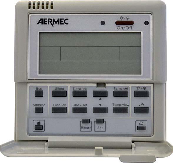
3 HBI control panel The HBI air-cooled heat pump is managed via a control panel with LCD mounted on the indoor unit. 2 All information regarding machine functioning and system settings are inserted and/or displayed via this control panel. The control panel is normally closed, therefore its keys are not visible and to access just open the lower door of the panel, revealing the function keys represented in the figure at the side Key Unit on/off key 2 LCD 3 Go back to main display key 4 Key used to set the internal unit address 5 SILENCED mode activation key 6 Key used to set the operational parameters 7 Key used to set the TIMER function 8 Key used to set the system clock 9 Key for increasing parameter value Key 0 Key for decreasing parameter value Key for setting the temperature range. 2 Key used to display the various system temperatures 3 Key used for functioning mode selection 4 Domestic hot water production ON/OFF key 5 Key used to block/release the protection for accidental pressing of the keys 6 Key used to go back to previous display 7 Key used to confirm selections 8 Key used for activation of AUTOMATIC heating mode _0 - IHBIFY GB 3
4 Control panel display The LCD with which the control panel is supplied, allows to display all information regarding system functioning or the active settings on the unit. Every function or parameter is identifi ed by one or more icons organised in different groups on the basis of the type of function to which they refer. The layout at the side summarises all icons present on the control panel LCD. B A B C 2 A D 2 C WARNING 2 D Index Icon Icon status Meaning Silenced mode On Active mode Off Mode not active On Active mode Off Mode not active 2 Heating mode Could indicate that: Flashing the anti-freeze function is active the instant hot water production function is active 3 Cooling mode On Active mode Off Mode not active On Active mode 4 Automatic heating mode Off Mode not active Indicates that the automatic heating mode is active during the time periods set Flashing in the system. On Active mode 5 Domestic hot water production mode Off Mode not active Indicates that the instant hot water production function is active, applied to the Flashing A production of DHW On active 6 Anti-legionella function Off not active Flashing Indicates that the anti-legionella cycle has not been completed correctly On Indicates that a room air set is being set 7 Environment air temperature Off not active Indicates that the room air temperature function is active during the time Flashing periods set in the system. On Indicates that a produced water set is being set Temperature of the water produced by the Off not active 8 HBI unit Indicates that the produced water function is active during the time periods set Flashing in the system. Indicates that the temperature to be reached in the HBI WT/WTS DHW On 9 HBI WT/WTS storage tank temperature storage tank is being set Off Mode not active Indicates that the temperature of the water produced by the solar collector (if On 0 Solar collector temperature installed) is being set, at which the solar heating pump is to be activated Off Mode not active 4 GB _0 - IHBIFY
5 Index Icon Icon status Meaning On Indicates that the parameters modification mode is active. Parameters setting mode Off Indicates that the parameters modification mode is not active. B On Indicates that the temperatures display mode is active. 2 Temperatures display mode Off Indicates that the temperatures display mode is not active. Index Icon Icon status Meaning On Indicates that an alarm condition is in progress. Alarm in progress Off Indicates that there are no alarms active. C On Indicates that the defrosting function is in progress. 2 Defrost function Off Indicates that the defrosting function is not in progress. Index Icon Icon status Meaning D Timer function 2 Countdown function 3 Weekly timer 4 Holiday timer 5 HBI internal unit pump 6 HBI outdoor unit Electric resistance (power level ) Electric resistance (power level 2) 9 DHW electric resistance 0 Thermostat BMS connection system 2 Hydraulic pump on solar heating system On Off Flashing On Off Flashing On Off Flashing On Off Flashing On Off On Off On Off On Off On Off On Off On Off On Off Indicates that a switch-on/off timer has been set No timer set Indicates that a switch-on/off timer is being set Indicates that a countdown has been set for switch-on/off No countdown set Indicates that a countdown is being set for switch-on/off Indicates that a weekly timer has been set No timer set Indicates that a weekly timer is being set Indicates that a timer has been set for the holidays No timer set Indicates that a timer is being set for the holidays Indicates that the hydraulic pump of the indoor unit is running Indicates that the HBI unit pump is not active. Indicates that the outdoor unit is active Indicates that the outdoor unit is not active Indicates that the HBI unit resistance is active at the first power level. Indicates that the HBI unit resistance is not active at the first power level. Indicates that the HBI unit resistance is active at the second power level. Indicates that the HBI unit resistance is not active at the second power level. indicates that the resistance in the HBI-WT/WTS DHW storage tank is active. indicates that the resistance in the HBI-WT/WTS DHW storage tank is not active. Indicates that the unit is managed by an external supervision system (all HBI control panel keys will be disabled) Indicates that the unit is not controlled via a BMS system Indicates that the pump on the solar heating system unit is running Indicates that the pump on the solar heating system unit is not running _0 - IHBIFY GB 5
6 HBI functioning mode The HBI system is managed via the control panel on the indoor unit. This interface, as illustrated in the previous pages, allows to select the functioning mode and set the different functions available, via the use of the keys present on the panel. The functioning modes possible on the HBI system are: COOLING Mode: This is the summer functioning mode. In this mode, the HBI system can produce water at a temperature between 7 and 30; however this interval can vary on the basis of the type of utility (on the basis of the presence or not of fan coils in the system) and on the basis of the type of reference set on the panel of the indoor HBI unit (control based on the temperature of the water produced by the indoor unit, or based on the room temperature; ATTENTION: to base the control of the HBI system on the room temperature it is necessary to install the room air sensor or an external thermostat as indicated in the installation manual); The intervals within which it is possible to set the job in cooling mode are: Reference Type of utility Work temperature range System with fan coil 8 Temperature of water produced ~ 25 (default: 8) System without fan coil 7 ~ 25 (default: 7) Environment air temperature All 8 ~ 30 (default: 20) HEATING Mode: This is the winter functioning mode. In this mode, the HBI system can produce water at a temperature between 25 and 55; however this interval can vary on the basis of the type of reference set on the panel of the indoor HBI unit (control based on the temperature of the water produced by the indoor unit, or based on the room temperature; ATTENTION: to base the control of the HBI system on the room temperature it is necessary to install the room air sensor or an external thermostat as indicated in the installation manual); The intervals within which it is possible to set the job in heating mode are: Reference Type of utility Work temperature range Temperature of water produced All 25 ~ 55 (default: 40) Environment air temperature All 8 ~ 36 (default: 26) DOMESTIC HOT WATER PRODUCTION mode: This is the specifi c functioning mode for the production of DHW. In this mode the HBI system can produce water at a temperature between 40 and 80 (default value 50). WARNING: the indoor HBI unit does not produce DHW directly, but just hot water for heating the content of the HBI WT/WTS storage tank (to which the anti-legionella cycle can be applied). + COOLING or HEATING + DOMESTIC HOT WATER PRODUCTION: The COOLING or HEATING mode can be combined with the PRODUCTION OF DOMESTIC HOT WATER; naturally, if these combined modes are used, the system will assign a priority to the system/domestic requests, on the basis of which the system will satisfy first one and then the other. WARNING: the default settings envision that the priority is assigned to the COOLING or HEATING mode, with respect to the production of domestic hot water. Therefore, if the system receives two simultaneous requests,the first to be satisfied will be for cooling or heating. 6 GB _0 - IHBIFY
7 s that can be performed from the control panel Below fi nd a summary layout of the functions that can be used via the control panel. These functions will be discussed in the following pages one by one in order to explain how these must be used and set on HBI systems. USER level functions ON/OFF due to system side functioning 2 Selecting work mode (Heating/Cooling) 3 ON/OFF for the production of domestic hot water (HBI WT/WTS) 4 ting the work set-points: (a) Room air temperature set (b) Produced water temperature set from the indoor unit (HBI E) (c) Water temperature set inside the storage tank (HBI WT/WTS) (d) Solar collector temperature set 5 Activate/deactivate silenced mode 6 Activate/deactivate automatic heating function INSTALLER level functions 7 Activate/deactivate keys lock TIMER ting 4 ting the LEVEL operational panels 8 ting the System clock 5 Displaying temperatures of the system 9 ting the INDIVIDUAL DAY TIMER! WARNING: these functions have been inserted to facilitate interventions on the unit by the installer or the technical after-sales service. The modification of these parameters by the user could cause damage to the unit. 0 ting WEEKLY TIMER ting HOLIDAY EXCLUSION TIMER 2 Display of the system timed programs 3 ting the timer for SILENCED mode _0 - IHBIFY GB 7
8 HBI control panel operational procedures ON/OFF due to system side functioning: The HBI unit allows to manage both the heating/air conditioning system (radiant panels, fan coils, low temperature radiators) and the system for the production of domestic hot water (with HBI WT/WTS storage tank). These two systems can function independently, therefore the HBI unit allows to activate or deactivate each mode individually. This function allows to activate or deactivate the heating or cooling modes on the system side. Note: the function does not set any specific mode, but activates the unit using the last work mode set.! WARNING: if a room thermostat has been installed it will no longer be possible to activate or deactivate the HEATING or COOLING functioning mode from the control panel of the indoor HBI unit. The thermostat will be highlighted on the display by the icon if it is installed In the example, a stand-by situation is taken as the starting point (i.e. the case in which no functioning mode is activated). The display will show the selected temperature, the example shows the temperature of the water inside the HBI WT/WTS storage tank, the day of the week 2, any information regarding the state of the system and information regarding time periods (if set). Fig. () In the example, the HEATING mode is activated, represented by the relative icon; Moreover, the temperature displayed is modifi ed 2 passing to the output temperature from the indoor unit (corresponding to the set work setpoint for the active mode).; Other information is also displayed regarding the system status 3. In this example the information is: - Indoor unit pump active; - Outdoor unit active. By pressing the key indicated, the HEATING or COOLING mode is activated (deactivated). Fig. (2) 8 GB _0 - IHBIFY
9 2 Selecting functioning mode (system water): This function allows to select the work mode from heating or cooling on the system side. Note: this selection is only possible if the unit is on.! WARNING: if a room thermostat has been installed it will no longer be possible to select the HEATING or COOLING functioning mode from the control panel of the indoor HBI unit. The thermostat will be highlighted on the display by the icon if it is installed By pressing the key shown in the fi gure, the functioning mode can be modifi ed for system water production (the domestic hot water production mode will be explained on the following pages). Pressing the key indicated will make the functioning mode change according to the following order: (a) HEATING; (b) COOLING; Both modes will be indicated by the relative icon shown on the display. Note: prolonged pressing (5 seconds) of the key indicated, will activate the hot water production function just with electric resistance. This function is indicated by the flashing heating icon and allows to produce hot water just using the indoor unit electric resistance. To exit this function, press the key indicated again for 5 seconds _0 - IHBIFY GB 9
10 3 ON/OFF for the production of domestic hot water (HBI WT/WTS): The HBI unit allows to manage both the heating/conditioning system (radiant panels, fan coils, low temperature radiators) and the system for the production of domestic hot water (with HBI WT/WTS storage tank). These two systems can function independently, therefore the HBI unit allows to activate or deactivate each mode individually. This function allows to activate or deactivate the domestic hot water production mode. Note: the HBI unit cannot produce DHW directly, but produces hot water used for the successive production of DHW via the HBI WT/WTS storage tank By pressing the key indicated, the domestic hot water production mode is activated (deactivated). In the example, the HEATING mode was already active and pressing the key indicated also activates the production of domestic hot water 3 (the priority between DHW as system hot water is set in the installer parameters). Moreover, the temperature displayed is modifi ed 2 by passing to the temperature inside the HBI WT/WTS storage tank. Note: prolonged pressing (5 seconds) of the key indicated, will activate the hot water production function just with electric resistance. This function is indicated by the flashing icon 3 and allows to produce hot water just using the indoor unit electric resistance (and eventually that of the HBI WT/WTS storage tank, on the basis of the relative settings). To exit this function, press the key indicated again for 5 seconds. 0 GB _0 - IHBIFY
11 4 ting the work sets: The HBI unit allows to manage the different parts of the system (room heating/air conditioning systems, domestic hot water production system, solar collector, etc...). To manage the system power requests correctly, the work set-point must be set. These can be: () (2) (a) System temperature set-point (based on the ROOM AIR temperature) This value indicates which temperature must be reached in the room in which the room air sensor is installed, supplied with the HBI unit (for further information, refer to the installation manual). Once the sensor detects the desired temperature, it will stop functioning of the HBI unit. This set-point is only visible if: the room air control has been set in the operational parameters; the room air probe accessory has been installed; one of the following modes is active: heating, cooling; () (2) (b) System temperature set-point (based on the PRODUCED WATER temperature) This value indicates at which temperature functioning of the HBI unit will be stopped; the system return water temperature value is controlled using this logic and once this value is that set, the HBI unit stops. This set-point is only visible if: the return water control has been set in the operational parameters (default setting); one of the following modes is active: heating, cooling; (c) HBI WT/WTS storage tank temperature set-point (domestic hot water production system) The HBI unit can manage the request for DHW. Once it is requested, the HBI unit switches the fl ow from the system to the HBI WT/WTS storage tank (acting on the 3-way diverter valve, not supplied. For further information regarding system components necessary, refer to the installation manual) and will produce hot water until the temperature set in this temperature set-point is reached. Once the temperature requested inside the HBI WT/ WTS storage tank has been reached, the unit will take the 3-way diverter valve towards the system. This set-point is only visible if: the presence of the HBI WT/WTS storage tank has been set in the operational parameters; the domestic hot water production mode is active; (d) Solar collector temperature set-point This value indicates at what temperature the pump must be activated on the solar collector; naturally to use this work set-point, the HBI unit must be installed on a system equipped with all components necessary for the management of a solar collector for integration on DHW (for further information, refer to the installation manual). This set-point is only visible if: the presence of a solar collector has been set in the operational parameters; the domestic hot water production mode is active; () the system temperature set-points based on the room air and return water temperature are in no case displayed at the same time. (2) during the automatic heating function it will not be possible to set any temperature value to apply to the system.! WARNING: if a room thermostat has been installed it will no longer be possible to set a work set-point from the control panel of the indoor HBI unit. The thermostat will be highlighted on the display by the icon if it is installed _0 - IHBIFY GB
12 In order to set the work set-point, the HBI unit must be on, activating the HEATING, COOLING mode or the PRODUCTION OF DHW By pressing this key, the unit switches on and one of the two HEATING or COOLING modes is activated. By pressing this key, the unit switches on and the domestic hot water production mode is activated. Fig. () By pressing the key indicated, enter the work set-point setting mode. Every time this key is pressed means a move from one set-point to the next (on the basis of the set-points available for the work mode active). Information is given on the display: The icon that represents the currently selected mode ; which could be: - room air temperature set; - system return water temperature setpoint; - HBI WT/WTS storage tank temperature set; - solar collector temperature set; The icon that represents the functioning mode 2 ; The current value set for the selected set-point 3 ; Fig. (2) 2 GB _0 - IHBIFY
13 Fig. (3) By pressing this key, the currently selected set-point value is confi rmed and the work set-point modification mode is exited. By pressing the ( ) key, the value of the currently selected set-point is increased (increase of every time it is pressed); By pressing the () key, the value of the currently selected set-point is decreased (decrease of every time it is pressed); 5 Activate/Deactivate silenced mode: The HBI unit is made up from an indoor and outdoor unit. The latter produces a determined sound level during its normal functioning. However, a function exists that allows to lower the sound level emitted by the outdoor unit. Note: the lowering of the sound level implies lowering of performance as the unit limits the fan speed and the frequency of the inverter compressor By pressing the key shown in the figure, the silenced mode can be activated or deactivated; this mode is identified by the icon _0 - IHBIFY GB 3
14 6 Activate/Deactivate automatic heating function: The HBI unit has an automatic heating function. This function allows the unit to autonomously calculate (on the basis of a climatic curve set in the opeational parameters) the temperature of the rooms in which the room air sensor is installed. Note: this function can be applied only to the heating mode. It is not available for any other mode By pressing the key indicated, the automatic heating mode is activated (or deactivated). In the example, the HEATING mode was already active and pressing the key indicated activates the automatic heating function, displaying the relative icon ; 4 GB _0 - IHBIFY
15 7 Activate/Deactivate keys lock: The HBI unit allows to lock the control panel keyboard in order to prevent accidental pressing of the keys. "EE" is shown on the display while this function is active Prolonged pressing (5 seconds) of the key shown in the fi gure, can activate or deactivate the keys lock function; this mode is identifi ed by the code on the display _0 - IHBIFY GB 5
16 8 ting the system clock: The HBI unit control panel allows to set different types of timer. To be able to use these functions it is first necessary to set the system clock. Note: the system time will be kept in the memory while the unit is live (also if in stand-by), therefore after every intervention that envisions removal of voltage from the unit it will be necessary to set the system clock again. Fig. () By pressing the key indicated, access system time setting. Once this key has been pressed, the current system time will be displayed ; the characters relative to the hours will flash. Fig. (2) By pressing the ( ) key, the system hours increase (increase of one hour every time it is pressed); By pressing the () key, the system hours decrease (decrease of one hour every time it is pressed); By pressing the key indicated, the hour is confi rmed and pass automatically to setting the minutes (moreover, the characters relative to the minutes will fl ash ). 6 GB _0 - IHBIFY
17 Fig. (3) By pressing the ( ) key, the system hours increase (increase of one minute every time it is pressed); By pressing the() key, the system hours decrease (decrease of one minute every time it is pressed); By pressing the key indicated, the minutes are confi rmed and pass automatically to setting the day (moreover, the day icon currently selected will fl ash ). Fig. (4) Pressing the ( ) key, pass to the next day of the week; Pressing the () key, pass to the previous day of the week; By pressing the key indicated, the current day of the week is confi rmed, exiting from the system weekly time setting function _0 - IHBIFY GB 7
18 9 ting the INDIVIDUAL DAY timer: The HBI unit control panel allows to set a daily timer for automatic switch-on/off of the unit. During execution of this time period, the unit will activate the functioning mode and the work set-point set by the user for the same time period. Note: The functioning mode and the work set-point set for the time period are only valid during execution of the same. The HBI unit envisions two different functions for the use of the time periods: the fi rst follows a logic called DIRECT, i.e. the user sets a switch-on time and a switch-off time, which represent the time period limits; the second follows a logic called COUNTDOWN, i.e. the user sets the start and the end of the time period, specifying the distance (in hours) from the moment it is set;! WARNING: The setting of the INDIVIDUAL DAY timer is valid just for the day in which this function is set. If the timer is to be repeated for several days, the WEEKLY TIMER function must be used (explained in the next pages). Fig. () By pressing the key indicated, access timer setting. Every time this key is pressed, a different icon will be displayed, representing a particular timer mode: () INDIVIDUAL DAY timer with direct logic; (2) INDIVIDUAL DAY timer with countdown logic; (3) WEEKLY timer; (4) HOLIDAYS EXCLUSION timer; To set the INDIVIDUAL DAY timer function, select possibility () or (2); for the remaining optionals, refer to the next section of this manual. 8 GB _0 - IHBIFY
19 Fig. (2) These keys allow to select the functioning mode to associate to the time period of the timer that is being set; By pressing the key indicated, the functioning mode selected is confi rmed If there is already a daily time period on the system, pressing this key would cause it to be deleted, taking the user to the main menu. Fig. (3) These keys allow to select the type of automatism to associate to the time period of the timer that is being set: Automatic switch-on (ON); Automatic switch-off (OFF); By pressing the key indicated, the type of automatism selected is confirmed _0 - IHBIFY GB 9
20 Fig. (4) These keys allow to select the work temperature to associate to the time period of the timer that is being set; By pressing the key indicated, the work set-point value selected is confirmed Fig. (5) 2345 The time setting (hours and minutes) can vary on the basis of the type of timer selected: Direct logic timer; into which the time is inserted at which the desired action is to be performed; Countdown logic timer; in which the time inserted represents the amount of time (from insertion) to countdown before the desired action is performed. 2 These keys allow to select the time (hours) at which to perform the automatism associated to the time period of the timer we are setting. By pressing the key indicated, the time selected is confi rmed 20 GB _0 - IHBIFY
21 Fig. (6) These keys allow to select the time (minutes) at which to perform the automatism associated to the time period of the timer we are setting. By pressing the key indicated, the time selected is confirmed _0 - IHBIFY GB 2
22 0 ting the WEEKLY timer: The HBI unit control panel allows to set a weekly timer for automatic switch-on/off of the unit. During execution of these time periods (up to 5 for every day of the week) the unit will activate the functioning mode and the work set-point set by the user for the same time period. Note: The functioning mode and the work set-point set for the time period are only valid during execution of the same. Fig. () By pressing the key indicated, access timer setting. Every time this key is pressed, a different icon will be displayed, representing a particular timer mode: () INDIVIDUAL DAY timer with direct logic; (2) INDIVIDUAL DAY timer with countdown logic; (3) WEEKLY timer; (4) HOLIDAYS EXCLUSION timer; To set the WEEKLY timer function, select possibility (3); for the remaining optionals, refer to the next section of this manual. 22 GB _0 - IHBIFY
23 Fig. (2) These keys allow to select the functioning mode to associate to the time period of the timer that is being set; By pressing the key indicated, the functioning mode selected is confi rmed Fig. (3) These keys allow to select the work temperature to associate to the time period of the timer that is being set; By pressing the key indicated, the work set value selected is confirmed _0 - IHBIFY GB 23
24 Fig. (4) Pressing the ( ) key, pass to the next day of the week; Pressing the () key, pass to the previous day of the week; By pressing the key indicated, the current day of the week is confi rmed 2 Fig. (5) 2345 The WEEKLY timer function, envisions the possibility of setting up to 5 daily time periods (indicated by a progressive number on the display 2 ), every time period envisions a start and end time, specifi ed by the user. 2 These keys allow to select the time (hours) at which to perform the START of the time period being set. By pressing the key indicated, the time selected is confi rmed 24 GB _0 - IHBIFY
25 These keys allow to select the time (minutes) at which to perform the START of the time period being set. By pressing the key indicated, the time selected is confirmed Fig. (6) These keys allow to select the time (hours) at which to perform the END of the time period being set. By pressing the key indicated, the time selected is confirmed Fig. (7) _0 - IHBIFY GB 25
26 Fig. (8) These keys allow to select the time (minutes) at which to perform the END of the time period being set. By pressing the key indicated, the time selected is confi rmed Fig. (9) Once the insertion of the time period has been completed (setting the start and end time), the system will take the remote panel to the situation described in Fig. (5), ready to insert the successive time period for the day selected. At this point the user can choose whether to: Insert a new time period by following the procedure illustrated by Fig.(5) up to Fig.(8) (this selection can be made a maximum of 5 times consecutively, because the system can manage up to 5 time periods every day); Interrupt the time periods insertion (for the day selected) by pressing the key. In this case, the system will re-start from the window illustrated in Fig.(4) (selecting the day on which to set the time periods) and it will be possible to set the time periods (by repeating the operations from Fig.(5) to Fig.(8)) for another day of the week. Exit the WEEKLY timer function by pressing the 2 key. In this case, the time period settings set in the WEEKLY timer will be activated. 26 GB _0 - IHBIFY
27 ting the HOLIDAYS EXCLUSION timer: The HBI unit control panel allows to temporarily exclude one or more days from those set in the WEEKLY timer function, in a way to prevent the unit respecting the time periods when it is not necessary (for example during a holiday period where no use is envisioned). Note: this function does not switch the unit on or off but is limited to preventing that one or more timed programs envisioned by the WEEKLY timer function are carried out.! WARNING: The setting of the HOLIDAYS EXCLUSION timer is only valid if the WEEKLY timer function has been previously set. Fig. () By pressing the key indicated, access timer setting. Every time this key is pressed, a different ion will be displayed, representing a particular timer mode: () INDIVIDUAL DAY timer with direct logic; (2) INDIVIDUAL DAY timer with countdown logic; (3) WEEKLY timer; (4) HOLIDAYS EXCLUSION timer; To set the HOLIDAYS EXCLUSION timer function,select possibility (4); _0 - IHBIFY GB 27
28 Fig. (2) By pressing the key indicated, access the setting mode for the HOLIDAYS EXCLUSION timer function; Fig. (3) Once a day has been selected on which to exclude the WEEKLY timer, the system will allow to continue to select other days until the user presses one of the keys to exit the HOLIDAYS EXCLUSION Timer function; Pressing the ( ) key, pass to the next day of the week; Pressing the () key, pass to the previous day of the week; By pressing the key indicated, the current day of the week is confi rmed. Every time this key is pressed, the current day selected will be confirmed; 28 GB _0 - IHBIFY
29 2 Display of the system times programs The HBI unit control panel allows the activation of a daily and a weekly timer. This function allows to summarise the clock settings set on the system. Note: this function does not modify any time setting, but only displays all settings linked to the system timer. Fig. () By pressing the key indicated and, HOLDING IT DOWN for 5 seconds, access the system time programs display. If this operation does not generate any display it means that no daily or weekly timings have been inserted into the system. Fig. (2) To exit the system timed programs display function, press one of the 2 keys; By pressing the keys indicated, the different icons in the position will be displayed; on the basis of this icon, it will be possible to establish to which type of timer the data displayed refer: INDIVIDUAL DAY (direct logic); INDIVIDUAL DAY (countdown logic); WEEKLY; HOLIDAYS EXCLUSION; _0 - IHBIFY GB 29
30 3 ting the timer for silenced mode The HBI unit control panel allows to set a timer or the silenced function. Note: for further information regarding silenced functioning, refer to function number 5. Fig. () By pressing the keys indicating and HOLDING DOWN for 5 seconds, the timer is activated for the silenced mode. 30 GB _0 - IHBIFY
31 Fig. (2) These keys allow to select the time (hour) at which to perform the silenced mode. By pressing the key indicated, the time selected is confirmed Fig. (3) These keys allow to select the time (minutes) at which to perform the silenced mode. By pressing the key indicated, the time selected is confirmed _0 - IHBIFY GB 3
32 Fig. (4) These keys allow to select the time (hour) at which to end the silenced mode. By pressing the key indicated, the time selected is confirmed Fig. (5) These keys allow to select the time (minutes) at which to end the silenced mode. By pressing the key indicated, the time selected is confi rmed 32 GB _0 - IHBIFY
33 4 ting the LEVEL operational parameters: This function allows to set a series of parameters (total 27 parameters) necessary for the correct functioning of the unit. These parameters regulate unit functioning on the basis of the type of installation carried out.! WARNING: this function is dedicated to the installer of the technical after-sales staff, as it is necessary to know the system in which the unit has been installed. The correct setting of these parameters is NECESSARY for the correct functioning of the unit. Index Description Value tings Default 0 This parameter indicates which type of reference is used for management of the unit; 0 Regulation based on the temperature of the water produced (this setting is mandatory if the room air sensor or dedicated room thermostat have not been installed); 0 Regulation based on the room temperature (this setting is ONLY possible This parameter enables or disable the test mode; WARNING: The unit must be OFF before activating this mode; If the value of this parameter is or 2, the test mode in cooling mode or in heating mode activates, switching the unit on and stops, switching it off. Otherwise this stops automatically after 5 minutes of continuous functioning; This parameter sets the unit of measurement for the temperature display; This parameter indicates the presence of a dedicated air thermostat; This parameter enables or disables the contemporaniety of loads (HBI unit and electric resistance inside HBI WT/WTS storage tank) during the production of DHW; This parameter enables or disable the antilegionella cycle; WARNING: If theunit envisions the installation of a HBI WT/WTS storage tank for the production of DHW, it is mandatory to enable the antilegionella cycle; This parameter enables or disables the anti-freeze function. This function allows to maintain the room temperature (room air sensor mandatory) within a determined safety threshold in order to prevent the room temperature from dropping too much. This parameter sets the priority between cooling request and that for production of domestic hot water, during cooling mode. This parameter sets the priority between heating request and that for production of domestic hot water, during heating mode. if the room air sensor or dedicated room thermostat have been installed); 0 The test mode is disabled; The test mode is activated in COOLING mode; This setting is to be used in the following cases: If necessary, top-up the refrigerant load; If commissioning takes place with outdoor air temperature below 0; 2 The test mode is activated in HEATING mode; This setting is to be used in the following cases: If commissioning takes place with outdoor air temperature over 35; 0 Unit of measurement (degrees Celsius); Unit of measurement (degrees Fahrenheit); 0 Room air thermostat NOT INSTALLED; Dedicated room air thermostat INSTALLED; The contemporaniety of the loads is DISABLED; 0 This means that if the production of DHW is requested, the HBI unit will be the only load to be used; The contemporaniety of the loads is ENABLED; This means that in the event of a request for the production of DHW, the HBI unit and electric resistance inside HBI WT/WTS storage tank are activated simultaneously; 0 Anti-legionella cycle DISABLED; Anti-legionella cycle ENABLED; 0 Anti-freeze function DISABLED; Anti-freeze function ENABLED; 0 0 Priority to the cooling request. This means that during functioning in cooling mode, the arrival of a request for the production of DHW, DOES NOT block unit functioning, satisfying the request for DHW only after having completed the conditioning system request. Priority to the request for production of DHW. This means that during functioning in cooling mode, the arrival of a request for the production of DHW, blocks unit functioning, satisfying the request for DHW and after having completed it, re-starts with the conditioning system request. Priority to the heating request. This means that during functioning in heating mode, the arrival of a request for the production of DHW, DOES NOT block unit functioning, satisfying the request for DHW only after having completed the heating system request. Priority to the request for production of DHW. This means that during functioning in heating mode, the arrival of a request for the production of DHW, blocks unit functioning, satisfying the request for DHW and after having completed it, re-starts with the heating system request _0 - IHBIFY GB 33
34 Index Description Value tings Default 0 This parameter indicates how to manage the Limits the electric resistance power to 50% of its nominal capacity. With electric resistance power, positioned in the this setting, the power supplied by the electric resistance is 3 kw; indoor unit; The electric resistance power is used at 00% of its nominal capacity. 2 With this setting, the power supplied by the electric resistance is 6 kw; This parameter indicates on which day the 0 SUNDAY as the day on which to perform the anti-legionella cycle anti-legionella cycle must be performed (this MONDAY as the day on which to perform the anti-legionella cycle setting is subject to activation of the cycle 2 TUESDAY as the day on which to perform the anti-legionella cycle itself, set in parameter 6); 3 WEDNESDAY as the day on which to perform the anti-legionella cycle 6 4 THURSDAY as the day on which to perform the anti-legionella cycle 5 FRIDAY as the day on which to perform the anti-legionella cycle 6 SATURDAY as the day on which to perform the anti-legionella cycle This parameter indicates the time the antilegionella cycle is to be performed, during the day selected in the previous parameter. This cycle will be repeated every week on the day and at the time envisioned. The value of this parameter can be selected within the range of values from 00 to 23; This parameter enables or disables the use of the electric resistance inside the HBI WT/ WTS storage tank; This parameter specifies the amount of temperature probes mounted on the storage tank. HBI WT/WTS; WARNING: the HBI WT/WTS accessory is supplied with two probes; for further details refer to the accessory installation manual; This parameter specifies the presence or not of the HBI WT/WTS storage tank; This parameter specifies whether any integrative heat sources are present; WARNING: only using the HBI WT/WTS accessory is it possible to envision any integrative sources; for further details refer to the accessory installation manual; 00 The anti-legionella cycle is performed at 24:00 0 The anti-legionella cycle is performed at 0:00 02 The anti-legionella cycle is performed at 02:00 03 The anti-legionella cycle is performed at 03: The anti-legionella cycle is performed at 23:00 0 The resistance inside the HBI WT/WTS storage tank is disabled; The resistance inside the HBI WT/WTS storage tank is enabled and switches on if the external temperature is lower than 0 during the production of DHW, switching off after the external unit compressor has stopped or if the external air temperature has risen to over 2; Indicates that one temperature probe has been installed; 2 Indicates that two temperature probes have been installed; 0 Indicates that the HBI WT/WTS accessory has NOT been installed Indicates that the HBI WT/WTS accessory HAS been installed 0 Indicates that integrative heat sources are not envisioned; Indicates that integrative heat sources are envisioned, connected to the secondary coil of the HBI WTS storage tank; This parameter specifies if fan coil terminals have been installed in the system; This parameter specifies whether the room air remote probe has been installed. The room air remote probe accessory is supplied. For further information, refer to the HBI unit installation manual; WARNING: the value of this parameter must be in line with that set in parameter ; Indicates that fan coils have not been envisioned in the system and supposing that the system envisions radiant panels, their use in cooling 0 mode could cause a condensation effect (if fed with water that is too cold), therefore if this parameter is set at 0, the minimum value that can be set for the water produced in cooling mode is 6; Indicates that fan coil terminals are installed in the system; if a mixed fan coil/radiant panels system is envisioned, it becomes necessary to install a 2-way valve (piloted from the HBI unit board) on the radiant panels line, which excludes them during functioning in cooling mode; for further information, refer to the installation manual; 0 Indicates that the probe has NOT been installed Indicates that the probe HAS been installed This parameter indicates the maximum threshold for the water produced in heating mode; 0 The temperature range of the produced water is from 25 to 55; this setting is envisioned only if radiant floors are not present in the system (in order not to allow water that is too hot feeding the radiant panels); The temperature range of the produced water is from 25 to 45; this setting is envisioned if radiant floors are present in the system; 34 GB _0 - IHBIFY
35 Index Description Range of values Default 20 This parameter indicates what is the temperature range within which the electric resistance is activated inside the HBI indoor unit in DHW production mode (for heating -20 ~ 8 0 or production of DHW); 2 This parameter indiates the water temperature threshold inside the HBI WT/WTS storage tank, over which the HBI indoor unit stops heating the water, leaving the electric 40 ~ resistance inside the tank to take the water to temperature set-point; 22 This parameter specifies the temperature at which the anti-legionella cycle will be performed: 40 ~ This parameter indicates the lower limit for the outdoor air in automatic heating mode (for further information regarding the function, refer to function number 6 in this -20 ~ 5-5 manual): 24 This parameter indicates the upper limit for the outdoor air in automatic heating mode (for further information regarding the function, refer to function number 6 in this 0 ~ 20 5 manual): 25 This parameter represents the differential applied to the system water or room air temperature set-point, in cooling functioning mode; 2 ~ This parameter represents the differential applied to the system water or room air temperature set-point, in heating functioning mode; 2 ~ This parameter represents the differential applied to the system water or room air temperature set-point, for the production of hot water; 2 ~ 8 3 Logic for domestic hot water production: () HBI WT/WTS storage tank temperature B A } C The water inside the HBI WT/WTS storage tank is heated via the hot water produced by the indoor unit; The water inside the HBI WT/WTS storage tank is heated via the electric resistance present in the storage tank itself; A B C Parameter 2; DHW set-point: Parameter 27; 3 The water inside the HBI WT/WTS storage tank is not heated; _0 - IHBIFY GB 35
36 2 ONCE THE UNIT IS INSTALLED, MAKE SURE THAT ALL OPERATIONAL PARAMETERS ARE SET CORRECTLY The function allows to modify the parameters indicated in the previous tables. Every parameter will be identifi ed by an index and a value 2 on the panel display. The fi rst is found in the previous tables and used to identify the meaning of the parameter, the other determines the value at which it is currently set. By pressing the key shown in the fi gure, access the LEVEL installer parameters setting menu; Fig. () Fig. (2) Pressing the ( ) key, pass to the next parameter; Pressing the () key, pass to the previous parameter; By pressing the key indicated, enter the modification mode for the parameter selected 36 GB _0 - IHBIFY
37 Fig. (3) Pressing the ( ) key, increase the parameter value; Pressing the () key, decrease the parameter value; By pressing the key indicated, the parameter value selected is saved Fig. (4) Once the operations described in Fig.3 have been completed, the panel goes back to the situation described in Fig.2 (parameter selection). From here it will be possible to select a new parameter and modify it in the same way in which the previous one was modifi ed, until one of the two keys indicated in have been pressed, to exit the LEVEL installer parameters modification function; _0 - IHBIFY GB 37
38 5 System temperature display: This function allows to display the temperatures detected by the different unit probes. This information can be used by the installer or technical after-sales staff to evaluate unit functioning! WARNING: This function is dedicated to the installer or technical after-sales assistance staff. 2 3 The system temperatures display function is indicated by the icon; every temperature is indicated by an index 2 and a value 3. To know to which temperature each index is referred, refer to the table below By pressing the key shown in the fi gure, access the system temperature display menu. Pressing the () key, pass to the next parameter; Pressing the () key, pass to the previous parameter; Index Temperature 0 Outdoor air temperature 02 Compressor temperature (INTAKE) 03 Compressor temperature (PRESSING) 04 Defrost temperature 05 Cooling circuit temperature (LIQUID SIDE) 06 Water inlet temperature 07 Water outlet temperature 08 Water temperature in the electric resistance 09 STORAGE TANK temperature (probe 2 = LOWER) 0 STORAGE TANK temperature (probe = UPPER) Room temperature (ROOM PROBE) 2 Cooling circuit temperature (GAS SIDE) 3 NOT USED Fig. () 38 GB _0 - IHBIFY
39 By pressing the key shown in the figure, escape the function by displaying the temperatures and return to the main menu. By pressing the key shown in the fi gure, escape the function by displaying the temperatures and return to the main menu. Fig. (2) _0 - IHBIFY GB 39
40 Alarms summary table! WARNING: In the event of an error, consult the installer or technical after-sales assistance staff. 2 If an alarm condition should occur, it is signalled on the remote panel display, via the general attention icon 2, and the icon that represents the error code. To establish the cause, refer to the error code table given below; Error code Cause of the error F4 Outdoor air temperature probe malfunctioning (outdoor unit) F6 Probe malfunctioning for the defrosting function F7 Probe malfunctioning on the compressor pressing line F5 Probe malfunctioning on the compressor intake line EF Outdoor unit fan malfunctioning E5 Compressor load protection error/inverter driver malfunction E High pressure alarm E3 Low pressure alarm E4 High temperature alarm on the pressing line C5 Indoor unit management malfunctioning E6 Communication error between indoor and outdoor unit Fc High pressure switch malfunctioning F9 Water outlet probe malfunctioning dh Water outlet probe malfunctioning (2) F Malfunctioning of the temperature probe on the liquid line F8 Water inlet probe malfunctioning FE Malfunctioning on probe number 2 on the HBI WT/WTS storage tank FL Malfunctioning on probe number on the HBI WT/WTS storage tank F3 Malfunctioning of the temperature probe on the gas line df Integrative heating systems output error F0 Malfunctioning of the room air remote probe Ec Malfunctioning of the 3-way diverter valve E2 Indoor unit anti-freeze alarm First stage malfunctioning of the HBI indoor unit resistance EH Second stage malfunctioning of the HBI indoor unit resistance Malfunctioning of the HBI WT/WTS storage tank electric resistance 40 GB _0 - IHBIFY
41
42
43
44 The technical data given in this documentation are not binding. AERMEC S.p.A. reserves the right to apply all the modifications deemed necessary for improving the product at any time. Les données mentionnées dans ce manuel ne constituent aucun engagement de notre part. Aermec S.p.A. se réserve le droit de modifier à tous moments les données considérées nécessaires à l amelioration du produit. Technical data shown in this booklet is not binding. Aermec S.p.A. shall have the right to introduce at any time whatever modifications deemed necessary to the improvement of the product. Im Sinne des technischen Fortsschrittes behält sich Aermec S.p.A. vor, in der Produktion Änderungen und Verbesserungen ohne Ankündigung durchzuführen. Los datos técnicos indicados en la presente documentación no son vinculantes. Aermec S.p.A. se reserva el derecho de realizar en cualquier momento las modificaciones que estime necesarias para mejorar el producto. AERMEC S.p.A I Bevilacqua (VR) - Italia Via Roma, Tel. (+39) Telefax (+39) (+39) com - aermec. com
Operation manual. Daikin Altherma Low temperature split EHBH04CBV EHBH08CBV EHBH11CBV EHBH16CBV
 EHBH04CBV EHBH08CBV EHBH11CBV EHBH16CBV EHVH04S18CBV EHVH08S18CBV EHVH08S26CBV EHVH11S26CBV EHVH16S26CBV English Table of contents Table of contents 1 About this document 2 2 About the system 2 2.1 Components
OPERATION MANUAL. Indoor unit for hot water heat pump system and options EKHBH016AB EKHBX016AB
 OPERATION MANUAL Indoor unit for hot water heat pump system and options EKHBH016AB EKHBX016AB EKHBH016AB*** EKHBX016AB*** Indoor unit for hot water heat pump system and options CONTENTS Page Introduction...1
REMOTE CONTROL FOR CHILLER MYCHILLER
 REMOTE CONTROL FOR CHILLER MYCHILLER GENERAL FEATURES... 3 MAIN FUNCTIONS AND EQUIPMENT:... 3 LCD DISPLAY... 4 KEYBOARD... 5 BOARD CONFIGURATION... 7 LIST OF MAIN PARAMETERS... 7 CONFIGURATION OF MAIN
ENGLISH. REMOTE CONTROL / ROOM THERMOSTAT Wireless INSTALLATION SERVICING AND USER MANUAL
 ENGLISH REMOTE CONTROL / ROOM THERMOSTAT Wireless INSTALLATION SERVICING AND USER MANUAL DANGER! Serious danger to safety and health ATTENTION! Possible dangerous situation for the product and the environment
User instructions DHP-AT
 User instructions DHP-AT VUGFC202 If these instructions are not followed during installation and service, Danfoss A/S liability according to the applicable warranty is not binding. Danfoss A/S retains
Operation manual. Daikin Altherma ground source heat pump EGSQH10S18AA9W. Operation manual Daikin Altherma ground source heat pump.
 English Table of contents Table of contents About this document About the system. Components in a typical system layout... 3 Operation 3 3. Overview: Operation... 3 3. The user interface at a glance...
> HGA AIR - WATER HEAT PUMPS FOR OUTDOOR INSTALLATION. Available range. Unit description. Options. Accessories
 > HGA AIR - WATER HEAT PUMPS FOR OUTDOOR INSTALLATION Available range Unit type IP Reversible heat pump (reversible on the refrigerant side) ECO-FRIENDLY REFRIGERANT GAS Versions (heat recovery) VB Base
Operation manual. Daikin Altherma ground source heat pump EGSQH10S18AA9W. Operation manual Daikin Altherma ground source heat pump.
 EGSQH0S8AA9W English Table of contents Table of contents About this document About the system Components in a typical system layout Operation Overview: Operation The user interface at a glance Buttons
1 DOCUMENT REVISION CONTROL ELEMENTS... 9
 CONTENTS Contents 1 DOCUMENT REVISION... 8 2 SOFTWARE VERSION... 8 3 BASIC DESCRIPTION... 8 4 CONTROL ELEMENTS... 9 4.1 BASIC DISPLAYS...10 4.2 CONTROL KEYS...11 4.2.1 Rotary button (Press / Turn)...11
INSTRUCTION MANUAL REMOTE CONTROL DEVICE EASYREMOTE
 INSTRUCTION MANUAL REMOTE CONTROL DEVICE EASYREMOTE Technical features Guide to LCD symbols Guide to keys Technical features Supply by communication bus Number of temperature levels 2 (DAY / NIGHT) Temperature
HMC300. Control unit. Operating Instructions. EMS plus (2014/10) O
 O") HMC300 Control unit EMS plus 6 720 808 471-00.1O Operating Instructions 6 720 813 192 (2014/10) Contents Contents Key to symbols and safety instructions................3 1.1 Key to symbols...........................
HMC300 Control unit EMS plus 6 720 808 471-00.1O Operating Instructions 6 720 813 192 (2014/10) Contents Contents Key to symbols and safety instructions................3 1.1 Key to symbols...........................
Elegance. SMT-700 User manual. Ver
 Elegance SMT-700 User manual Ver 3.0. 0807 Congratulations on the purchase of your new Thermostat! Your new air conditioning system thermostat has been built using the best components and design philosophy
1. COMMISSIONING OF THE BOILER en DESCRIPTION FUNCTION BUTTON DESCRIPTION SYMBOL DISPLAY
 RC 06 0712_1403 it - Istruzioni TELECONTROLLO en - Remote controller instruction hu - Utasítás TÁVVEZÉRLÉS ru - Руководство по эксплуатации pl - Instrukcja obsługi { 1. Commissioning of the boiler 26 2.
USER MANUAL S203. Controller for three circuits. - control for 2 heating circuits - 1 domestic hot water control. Saving energy, creating comfort
 USER MANUAL S203 Controller for three circuits - control for 2 heating circuits - 1 domestic hot water control Saving energy, creating comfort This user manual consists of two parts. Issues that are intended
OPERATION MANUAL. Packaged air-cooled water chillers and packaged reversible air to water heatpumps EWAQ009ACV3 EWAQ010ACV3 EWAQ011ACV3
 OPERATION MANUAL Packaged air-cooled water chillers and packaged reversible air to EWAQ009ACV3 EWAQ010ACV3 EWAQ011ACV3 EWYQ009ACV3 EWYQ010ACV3 EWYQ011ACV3 EWAQ009ACW1 EWAQ011ACW1 EWAQ013ACW1 EWYQ009ACW1
ST 53.1 User s manual
 Tech - 1 - ST 53.1 User s manual Table of contents I. Safety... 3 II. Description... 4 III. Installation... 4 IV. Operating the Controller... 6 IV.a) Principle of Operation... 6 IV.b) Control... 6 V. Controller
User Manual for model
 User Manual for model RKA 24 /20 Wall mounted storage combi boiler premix condensing boiler CE 0694 Technical specification RADIANT BRUCIATORI S.p.A. Montelabbate RKA 24.20 - RAD - ING - MAN.UT - 1309.1
OPERATION MANUAL. Daikin Altherma indoor unit EKHVMRD50ABV1 EKHVMRD80ABV1 EKHVMYD50ABV1 EKHVMYD80ABV1
 OPERATION MANUAL EKHVMRD50ABV1 EKHVMRD80ABV1 EKHVMYD50ABV1 EKHVMYD80ABV1 EKHVMRD50+80ABV1 EKHVMYD50+80ABV1 CONTENTS Page 1. Definitions... 1 2. Introduction... 2 2.1. General information... 2 2.2. Scope
Operation manual. Daikin Altherma Low temperature split EHBH04CB EHBH08CB EHBH11CB EHBH16CB EHBX04CB EHBX08CB EHBX11CB EHBX16CB
 EHBH04CB EHBH08CB EHBHCB EHBH6CB EHBX04CB EHBX08CB EHBXCB EHBX6CB EHVH04S8CB EHVH08S8CB EHVH08S6CB EHVHS8CB EHVHS6CB EHVH6S8CB EHVH6S6CB EHVX04S8CB EHVX08S8CB EHVX08S6CB EHVXS8CB EHVXS6CB EHVX6S8CB EHVX6S6CB
Condensing Boiler RS100 Controller Training Program
 Condensing Boiler RS100 Controller Training Program Training Program #501102A 062311 www.rinnai.us 2009 Rinnai America Corporation Features and Benefits The RS100 connects directly to the boiler and acts
DFZ. In Cab Control Description and Operation
 DFZ In Cab Control Description and Operation Index 1. Description of the control unit 1.1. Switching on the control unit 1.2. Diesel operation setting-up 1.3. Setting-up of the operation set point 1.4.
RADIO WAVE WEEKLY PROGRAMMABLE THERMOSTAT CH150RF
 RADIO WAVE WEEKLY PROGRAMMABLE THERMOSTAT CH150RF INDEX Introduction...3 Controls and indications...4 Controls...4 Indications...5 User manual...6 Setting the date and time...6 Summer/Winter selection...7
Operation manual. Daikin Altherma low temperature monobloc EBLQ05CAV3 EBLQ07CAV3 EDLQ05CAV3 EDLQ07CAV3
 EBLQ05CAV3 EBLQ07CAV3 EDLQ05CAV3 EDLQ07CAV3 English Table of Contents Table of Contents 1 About this document 2 2 About the system 2 2.1 Components in a typical system layout... 2 3 Operation 3 3.1 Overview:
OPERATION MANUAL. Indoor unit for air to water heat pump and sanitary warm water tank for air to water heat pump system EKHBH007A EKHBX007A
 OPERATION MANUAL Indoor unit for air to water heat pump and sanitary warm water tank for air to water heat pump system EKHBH007A EKHBX007A EKHBH007A*** EKHBX007A*** Indoor unit for air to water heat pump
VARIABLE MULTI FLOW VMF integrated system Hydronics at your command
 VARIABLE MULTI FLOW VMF integrated system Hydronics at your command VMF Variable Multi Flow Total control Green Comfort Noiselessness Savings The VMF System, the result of years of research and development
SOTTOSTAZIONI PER TELERISCALDAMENTO DISTRICT HEATING SUBSTATIONS
 SOTTOSTAZIONI PER TELERISCALDAMENTO DISTRICT HEATING SUBSTATIONS INDEX Ed. 20150422 GENERAL INFORMATION... 2 Before installing... 2 Materials and PED (97/23/CE) Standards... 3 SKID-TYPE DISTRICT HEATING
ENERGY LIGHT USER S GUIDE ENERGY LIGHT USER S GUIDE
 ENERGY LIGHT USER S GUIDE Release January 2001 CONTENTS 1.0 GENERAL CHARACTERISTICS... 4 1.1 MAIN CHARACTERIS TICS... 4 2.0 USER INTERFACE (CODE C5121230)... 5 2.1 DISPLAY... 5 2.2 MEANING OF THE LEDS...
IE Instructions and warning book CRONO 7. Weekly digital chronothermostat
 IE Instructions and warning book CRONO 7 Weekly digital chronothermostat Dear Client, Our compliments for having chosen a top-quality Immergas product, able to assure well-being and safety for a long period
DPC-1 Programmable digital thermostat with communication Versión 2.0. Technical Information. Ref: N
 DPC-1 Programmable digital thermostat with communication Versión 2.0 Ref: N-27360 1108 Technical Information I S O 9 0 0 1 ER-0028/1991 Johnson Controls Manufacturing España, S.L. is participating in the
Control Application. Supplement - ACVMax
 prestige Control Application Supplement - ACVMax L I S T E D WARNING This document is intended to be used by a factory trained and qualified heating contractor or service technician only. Read all instructions
ECL Comfort 210 / 296 / 310
 User Guide ECL Comfort 210 / 296 / 310 English version www.danfoss.com Safety Note Necessary assembly, start-up, and maintenance work must be performed by qualified and authorized personnel only. 2 Danfoss
USER MANUAL ACQUAHOME 32 B BLU
 USER MANUAL ACQUAHOME 32 B BLU Dear Customer, Thank you for preferring a T heating unit, a modern, high-quality product that is able to guarantee your maximum well-being for a long period of time, with
Installation and user manual
 Installation and user manual Please read carefully and retain for future reference Models EcoHeat: C3, C5, C6, C8, C9, C11, C12 Rev.1_09-07-15 Page 1 Table of Contents 1 IMPORTANT: WARNINGS 1.1 GENERAL
XC1008D -XC1011D- XC1015D and VGC810
 Electronic Controller for Compressor Racks XC1008D -XC1011D- XC1015D and VGC810 Instructions Manual INDEX 1. GENERAL WARNING 4 1.1 PLEASE READ BEFORE USING THIS MANUAL 4 1.2 SAFETY PRECAUTIONS 4 2. WIRING
prestige Control Application Supplement - ACVMax
 2015-10 Prestige ACVMax Control Sup 12-14-15_ACVMax_Control 12/15/15 7:36 AM Page 1 prestige Control Application Supplement - ACVMax L I S T E D WARNING This document is intended to be used by a factory
SD2. Differential Controller. Operating and Installation Instructions F2 72.3
 SD2 Differential Controller Operating and Installation Instructions F2 72.3 i Please follow the safety information and read these Instructions carefully before putting the system into operation. Safety
Operation manual. Rooftop Packaged Unit
 Operation manual Rooftop Packaged Unit odels: UATYQ20ABAY1 UATYQ25ABAY1 UATYQ30ABAY1 UATYQ45ABAY1 UATYQ50ABAY1 UATYQ55ABAY1 UATYQ65ABAY1 UATYQ75ABAY1 UATYQ90ABAY1 UATYQ110ABAY1 UATYQ115ABAY1 UATYQ20AFC2Y1
Aqua 1 plus Air-water heat pumps for domestic hot water production
 Aqua 1 plus Air-water heat pumps for domestic hot water production THE FLEXIBLE EFFICIENCY is a range of heap pumps for domestic hot water production, fit for small residential applications. It is the
Table of Contents. Product Image 1 Locking/Unlocking the neoair 24 Table of Contents 2 Frost Protection 25 What is a Programmable Room Thermostat?
 Table of Contents Product Image 1 Locking/Unlocking the neoair 24 Table of Contents 2 Frost Protection 25 What is a Programmable Room Thermostat? 3-4 Power ON/OFF 26 Holiday Programming 27 Installation
Operating instructions SENTRI4 Control panel based Fire detection and alarm system
 1 2 3 4 5 6 7 8 9 10 11 12 13 14 15 16 17 18 19 20 21 22 23 24 25 26 27 28 29 30 30 32 Zones Healthy 15:45 Fault Power Fault System Fault SenTRI 4 Fire System Designed to EN54 Pt 2 & 4 Operating instructions
Refrigerated air dryers
 Refrigerated air dryers OPERATING AND MAINTENANCE MANUAL Original instructions 38178800319 OPERATING AND MAINTENANCE MANUAL - Contents 1 CONTENTS CONTENTS... 1 Chapter 1 IDRY ELECTRONIC CONTROLLER...
Grant Aerona³. Air to Water High Efficiency Heat Pump Range. User Instructions
 Grant Aerona³ Air to Water High Efficiency Heat Pump Range User Instructions UK DOC 0112 Rev 1.0 April 2017 Special Tex t Formats The following special text formats are used in this manual for the purposes
OPERATING MANUAL UTY-RNNYM P/N English
 OPERATING MANUAL English UTY-RNNYM P/N9373329206-04 OPERATING MANUAL CONTENTS SAFETY PRECAUTIONS... 1 NAME OF PARTS... 2 PREPARATORY OPERATION... 3 OPERATION... 4 TIMER FUNCTIONS... 6 ON/OFF TIMER... 6
For the owner and the heating engineer. Operating and Installation Manual VRC 400. Programmable weather compensator with separat HW time control
 For the owner and the heating engineer Operating and Installation Manual VRC 400 Programmable weather compensator with separat HW time control GB Contents Contents Notes on the documentation..... 4 Symbols
SHERPA DHW 75. Th e multifunctional air-water split heat pump. COP > 4 DHW 75 C
 SHERPA Th e multifunctional air-water split heat pump. PATENTED TECHNOLOGY The combination of an inverter air-water heat pump together with a water-water heat pump allows heating/ and high temperature
OPERATION MANUAL. Unit and options for air to water heat pump system EDHQ011BB6V3 EDHQ014BB6V3 EDHQ016BB6V3 EDHQ011BB6W1 EDHQ014BB6W1 EDHQ016BB6W1
 OPERATION MANUAL Unit and options for air to water heat pump system EDHQ011BB6V3 EDHQ014BB6V3 EDHQ016BB6V3 EDHQ011BB6W1 EDHQ014BB6W1 EDHQ016BB6W1 EDLQ011BB6V3 EDLQ014BB6V3 EDLQ016BB6V3 EDLQ011BB6W1 EDLQ014BB6W1
Owner s Manual. Part Number 33CS250-FS and 33CS220-FS
 Debonair 33CS Flush-Mounted Flatstat Commercial Programmable Thermostat IMPORTANT: Read entire instructions before programming the thermostat. Owner s Manual Part Number 33CS250-FS and 33CS220-FS GENERAL
OWNER S MANUAL. Part Number P
 OWNER S MANUAL CPV230 Commercial Thermostat Part Number P374-2300 CONTENTS Page GENERAL...2 CONFIGURATION...3-12 Thermostat Display...3 Heat or Cool Indicator...4 Thermostat Front Panel Buttons...4 Thermostat
INSTRUCTION FOR THE USER THC V E OIL BLU
 INSTRUCTION FOR THE THC V E OIL BLU CONTENTS General safety information 4 Precautions 4 Control panel 5 Mode selection 8 User levels 10 Start-up 12 Temporary shutdown 15 Preparing for extended periods
SAS908WHB-3-RF/B WIRELESS THERMOSTAT
 SAS908WHB-3-RF/B WIRELESS THERMOSTAT Installation and operation instructions 908WHB-3-RF/B can replace most common residential thermostat and is designed to be used with electric, gas or oil heating control
NR-20DU. Keep this manual near this remote controller for future reference whenever maintenance or service is required.
 NR-20DU Keep this manual near this remote controller for future reference whenever maintenance or service is required. Contents Safety Instructions 3 Included Items 4 Connecting the Extension Cable 5 Attaching
Table of Contents. Product Image Table of Contents What is a Programmable Room Thermostat? Installation Procedure
 1 Model: 1 Table of Contents Product Image Table of Contents What is a Programmable Room Thermostat? Installation Procedure 1 2 3-4 5-6 Mode Select Pairing the ProTouch iq Hub Pairing the ProTouch iq What
Indoor unit for air to water heat pump system and options
 OPERATION MANUAL Indoor unit for air to water heat pump system and options English Manuel d'utilisation Unité intérieure pour système de pompe à chaleur air à eau et options Français Manual de operación
Regulation EASY CLIMA VERSION 1.6 TECHNICAL MANUAL
 Regulation EASY CLIMA VERSION 1.6 TECHNICAL MANUAL WARNINGS SAFETY WARNINGS Read this manual carefully before installation and/or use of the equipment and keep it in an accessible place. The Manufacturer
USERS MANUAL FOR GAS BOILERS
 USERS MANUAL FOR GAS BOILERS PLEASE READ THE MANUAL CAREFULLY: IT CONTAINS IMPORTANT INFORMATION REGARDING SAFETY, INSTALLATION, USE AND MAINTENANCE OF THE APPLIANCE MODELS: NOVADENS 24 NOVADENS 24C NOVADENS
THESE INSTRUCTIONS SHOULD BE READ CAREFULLY AND RETAINED FOR FUTURE REFERENCE.
 TE-700I Installation and Operating Instructions Haverland TOWELS THESE INSTRUCTIONS SHOULD BE READ CAREFULLY AND RETAINED FOR FUTURE REFERENCE. GENERAL RECOMMENDATIONS: * Please read these installation
Owner s Manual. Part Number 33CS250-01
 33CS Commercial Programmable Thermostat IMPORTANT: Read entire instructions before programming the thermostat. Owner s Manual Part Number 33CS250-01 GENERAL Carrier s 7-day, commercial, programmable thermostats
User s guide. Multiple programming Electronic thermostat
 SYSTÈME QUALITÉ CERTIFIÉ - REGISTERED QUALITY SYSTEM User s guide STE402P+ Multiple programming Electronic thermostat Energy Verified For further information or to consult this guide online, please visit
50110_HM-neoStat-2014_Layout 1 31/10/ :33 Page 1 neo
 neo Model: Available in : Sapphire Black and Glacier White 1 Wavin neo Table of Contents Product Image 1 Optional Features 19-22 Table of Contents 2 Re-calibrating the Thermostat 23 What is a Programmable
ATC32U01 igate Communicating, Programmable Thermostat
 ATC32U01 igate Communicating, Programmable Thermostat User Manual 97B0055N02 Rev.: 7/2/12 Table of Contents Section Title Page Menu Navigation Shortcuts 3 1.0 Operating Mode Selection 3 2.0 Temperature
User Manual RBS 24. for model CE series ENERGY. Wall mounted instantaneous combi boiler room sealed chamber
 User Manual for model RBS 24 series ENERGY Wall mounted instantaneous combi boiler room sealed chamber CE 0694 RBS 24 - SERIE ENERGY - RAD - ING - MAN.UT - 1407.1 - DIGITECH TR - MIAH6 - E04 Technical
PROGRAMMABLE 7-DAY THERMOSTAT
 PROGRAMMABLE 7-DAY THERMOSTAT Installation and user instruction This instructions to be retained by the user 1 Thank you for choosing Riello s weekly programmer.. This central heating control device is
Clima Infrared Radiant & Convection Panel
 Clima Infrared Radiant & Convection Panel Model S2030/1 Operating and Instruction Manual Please retain these instructions in a safe place for future reference. Ed. 05112015 cjw 1 References: n 1 min. 50cm
Installation, Start-Up, and Operating Instructions
 Installation, Start-Up, and Operating Instructions CONTENTS Page SAFETY CONSIDERATIONS...1 GENERAL...1 INSTALLATION...1-5 Install Batteries...1 Select Transmitter Location (Optional)...1 Mount Transmitter
ComfortSense 7500 Commercial Thermostat. User Guide
 ComfortSense 7500 Commercial Thermostat User Guide 507505-02 6/2018 Supersedes 5/2017 Table of Contents Features...2 Home Screen Temperature Indicator...2 Home Screen Information...3 Operating Mode Selection...5
Type UCG/UDG. English...1 Français...7 Español Up button. OK button. Down button
 USER MANUAL Type UCG/UDG 57116D 06/12 (MBC) 1.10 2012 OJ Electronics A/S...1 Français...7 Español... 14 Type UCG/UDG Contents Introduction...1 First Time Settings...1 Ground Fault Circuit Interrupter (GFCI)...1
Product Manual SZ1009
 Product Manual SZ1009 Conventional Heating & Cooling Thermostats with Heat Pump Mode Communicating Thermostats Description The SZ1009 is a microprocessor-based mable thermostats designed for conventional
ETNC24-FC-BAC-PIR-01 Owner s manual & Technician Settings
 ETNC-FC-BAC-PIR- Rev. Index Operating instructions....- Turning the thermostat and OFF Selecting temperature scale Adjusting the Set point temperature (for set point and set points configurations) Selecting
Instruction manual. Aluminium radiator with ceramic heart. Smart Electric Heaters
 Instruction manual Aluminium radiator with ceramic heart Smart Electric Heaters READ THIS CAREFULLY BEFORE USING THIS DEVICE FOR THE FIRST TIME. PAY ATTENTION: to avoid overheating, do not cover the appliance.
User manual DHP-AQ VUGFB102
 User manual DHP-AQ VUGFB102 Danfoss A/S reserves the right to make changes to components and specifications without prior notice. 2010 Danfoss A/S. The Swedish language is used for the original instructions.
Underfloor Heating Programmable Thermostat
 Underfloor Heating Programmable Thermostat t: 093 4906 m: 0794 69635 w: www.gs-ufh.co.uk e: gs@warmfloors.co.uk POWER CLOCK H A DOWN UP TO CHANGE THE TIMINGS AT ANY STAGE DURING THE PROCESS YOU CAN PRESS
Operation manual. ROTEX HPU hybrid heat pump module RHYHBH05AA RHYHBH08AA RHYHBX08AA. Operation manual ROTEX HPU hybrid heat pump module.
 RHYHBH05AA RHYHBH08AA RHYHBX08AA English Table of contents Table of contents Target audience End users Documentation set About this document About the system Components in a typical system layout Operation
CRIMSON & CRIMSON MAX
 High efficiency water/water and geothermal heat pumps 5 114 General High efficiency water/water and geothermal heat pumps. Ideal for heating, cooling and production of domestic hotwater with total or partial
Installation, Programming and Operating Guide for Digital, Programmable Thermostat with Smart Fan Technology. with SFT (Smart Fan Technology )
") with SFT (Smart Fan Technology ) Installation, Programming and Operating Guide for Digital, Programmable Thermostat with Smart Fan Technology EclipseEfficiencies.com 2016 Eclipse Efficiencies, Inc. All
with SFT (Smart Fan Technology ) Installation, Programming and Operating Guide for Digital, Programmable Thermostat with Smart Fan Technology EclipseEfficiencies.com 2016 Eclipse Efficiencies, Inc. All
R. Boiler Energy Management System FW 200. Operating Instructions for the User (2010/05)
") 720 12 481-00.1R oiler Energy Management System FW 200 Operating Instructions for the User 2 US/CA Dear Customer, The controls are the brain of your heating system. We have set it at the factory so that
720 12 481-00.1R oiler Energy Management System FW 200 Operating Instructions for the User 2 US/CA Dear Customer, The controls are the brain of your heating system. We have set it at the factory so that
GA01HC-02. Service manual. Room Panel. Programme version 01a. Operating with GH07EA regulator for controlling electrode boilers
 Room Panel GA01HC-02 Operating with GH07EA regulator for controlling electrode boilers Programme version 01a Service manual We request that users carefully study applicable Instructions before connecting
Updated: 17/03/2010 ELECTROLUX. CAREL ir33. Quick reference Handbook. Ver. 1.1 Eng. Pag.1/12
 CAREL ir33 Quick reference Handbook Pag.1/12 MAIN FEATURES OF THE INSTRUMENT USER INTERFACE 1. ON/OFF switch button UP button to increase temperature values 2. DOWN button to decrease values - Activates/deactivates
Table of Contents. Model: Series. Available in : Sapphire Black and Glacier White. Product Image. 20 Table of Contents.
 1 Model: Available in : Sapphire Black and Glacier White Table of Contents Product Image 1 Frost Protection 20 Table of Contents 2 Power ON/OFF 21 What is a Programmable Room Thermostat? Installation Procedure
- Brochure D 542. Introduction. Features. tekmarnet 4 Thermostat /05. 5 Data Brochure Control settings wiring instructions
 - Brochure tekmarnet 4 Thermostat 542 D 542 06/05 1 Information Brochure Choose controls to match application Application Brochure Design your mechanical applications 2 3 Rough In Wiring Rough-in 4 Wiring
WATER HEATER ELECTRONIC CONTROLLER USER MANUAL
 WATER HEATER ELECTRONIC CONTROLLER USER MANUAL UPPER LED READOUT LED ICONS LOWER LED READOUT PVI INDUSTRIES, LLC - Fort Worth, Texas 76111 - Web www.pvi.com - Phone 1-800-433-5654 Page 1 / 7 PV500-40 03/17
Heating Controller SDC. District Heating Controller DHC 43 OPERATING INSTRUCTIONS
 Heating Controller SDC District Heating Controller DHC 43 OPERATING INSTRUCTIONS Copyright 2002 Honeywell Inc. EN2H-0220 GE51 R0802 SDC / DHC 43 Operating Instructions EN2H-0220 GE51 R0802 Contents SDC
Table of Contents. SLIMLINE Series MODEL: SLIMLINE
 Table of Contents Product Image 1 Table of Contents 2 What is a Programmable Room Thermostat? 3-4 Installation Procedure 5-6 LCD Display 7-8 Setting the Clock 9 Temperature Display 10 Setting the Comfort
OWNER S MANUAL. Part Number P RF
 OWNER S MANUAL CPE230RF Commercial Programmable Thermostat Wireless Transmitter Part Number P474-2300RF CONTENTS Page GENERAL... 2 CONFIGURATION... 3-12 Transmitter Display... 3 Transmitter Indicator...
AUTO CM CM USER GUIDE
 1 2 3 4 5 6 7 AUTO CM701...2-6 CM707...7-11 USER GUIDE CM701 - USER GUIDE Description The Honeywell CM701 is a programmable room thermostat designed to control your heating system efficiently, providing
- Data Brochure tekmarnet 4 Thermostat 542e
 - Data Brochure tekmarnet 4 Thermostat 542e D 542e 03/08 1 Information Brochure Choose controls to match application 2 Application Brochure Design your mechanical applications 3 Rough In Wiring Rough-in
ST Wiring diagram. Product description. Four-stage controller. Order number
 ST96-35.16 Four-stage controller Order number 99.2 Wiring diagram Product description The four-stage controller with 4-digit setpoint and actual value display, 3 keys and 4 relays was developed for the
Field settings table [6.8.2] =... ID66F2. Applicable units *BLQ05CAV3 *DLQ05CAV3 *BLQ07CAV3 *DLQ07CAV3. Notes (*1) *B* (*2) *D* 1/8
![Field settings table [6.8.2] =... ID66F2. Applicable units *BLQ05CAV3 *DLQ05CAV3 *BLQ07CAV3 *DLQ07CAV3. Notes (*1) *B* (*2) *D* 1/8](/thumbs/95/126074615.jpg "Field settings table [6.8.2] =... ID66F2. Applicable units *BLQ05CAV3 *DLQ05CAV3 *BLQ07CAV3 *DLQ07CAV3. Notes (*1) *B* (*2) *D* 1/8") /8 [6.8.2] =... ID66F2 Applicable units *BLQ5CAV3 *DLQ5CAV3 *BLQ7CAV3 *DLQ7CAV3 Notes (*) *B* (*2) *D* 2/8 User settings Preset values Room temperature 7.4.. Comfort (heating) R/W [3-7]~[3-6], step: A.3.2.4
/8 [6.8.2] =... ID66F2 Applicable units *BLQ5CAV3 *DLQ5CAV3 *BLQ7CAV3 *DLQ7CAV3 Notes (*) *B* (*2) *D* 2/8 User settings Preset values Room temperature 7.4.. Comfort (heating) R/W [3-7]~[3-6], step: A.3.2.4
Drayton Digistat +3RF
 Drayton Digistat +3RF Programmable Room Thermostat Wireless 5-2 Day / 7 Day Model: RF701/22092 Power Supply: Battery - Thermostat Mains - Digistat SCR Invensys Controls Europe Customer Service Tel: 0845
NA G µair CONNECT 2
 NA 9.41 G 7-216 µair CONNECT 2 Control manual EN CONTENTS PAGE 1. GENERAL INFORMATION 2 2. COMPONENTS 3 2.1 On the front: 3 2.2 On the rear: 4 3. MENU TREE 7 4. ACCESS LEVEL (menu 8) 1 5. CONFIGURING
User reference guide. Daikin Altherma Low temperature split EHBH04CB EHBH08CB EHBH11CB EHBH16CB EHBX04CB EHBX08CB EHBX11CB EHBX16CB
 EHBH04CB EHBH08CB EHBH11CB EHBH16CB EHBX04CB EHBX08CB EHBX11CB EHBX16CB EHVH04S18CB EHVH08S18CB EHVH08S26CB EHVH11S18CB EHVH11S26CB EHVH16S18CB EHVH16S26CB EHVX04S18CB EHVX08S18CB EHVX08S26CB EHVX11S18CB
IE Instructions and warning book SUPER CAR. Remote control
 IE Instructions and warning book SUPER CAR Remote control Dear Customer, We wish to congratulate you on having chosen one of the Immergas high quality products that will guarantee your wellbeing and safety
Installation Instructions / User s Manual TSTAT0406 and TSTAT0408
 997-060180-5 Installation Instructions / User s Manual TSTAT0406 and TSTAT0408 4 HEAT 2 COOL DUAL FUEL TSTAT0406 & TSTAT0408-4 WIRE CAPABLE THERMOSTAT (NAXA00201DB Daughter Board sold separately) LEFT
Operating instructions Vigilon panel and Network node Fire detection and alarm system
 Healthy 15:45 Fault Power Fault Vigilon Fire System GENT 2015 Designed to EN54 Pt 2 & 4 System Fault Operating instructions Vigilon panel and Network node Fire detection and alarm system Test Fire Fault/Dis
Climapro 2. User manual. wireless room thermostat without receiver. To be left with the user.
 Climapro 2 User manual To be left with the user wireless room thermostat without receiver www.glow-worm.co.uk table of contents READ CAREFULLY BEFORE USING 1 Introducing your Climapro 2... 3 1.1 Description...
ComfortSense 7500 Thermostat. User Guide
 ComfortSense 7500 Thermostat User Guide 507503-02 6/2018 Supersedes 5/2017 Table of Contents Features...2 Home Screen Temperature Indicator...3 Home Screen Information...3 Operating Mode Selection...6
User s Manual. THE iq Drive SYSTEM USER S INFORMATION IMPORTANT. Variable Speed Ultra-High SEER Split System IMPORTANT NOTE
 User s Manual Variable Speed Ultra-High SEER Split System These units have been designed and tested for capacity and effi ciency in accordance with ARI standards. These outdoor air conditioning units are
Owner s Manual AIR TO WATER HEAT PUMP. Hydro Unit HWS-804XWHM3-E HWS-804XWHT6-E HWS-804XWHT9-E HWS-1404XWHM3-E HWS-1404XWHT6-E HWS-1404XWHT9-E
 AIR TO WATER HEAT PUMP Hydro Unit Model name: HWS-804XWHM3-E HWS-804XWHT6-E HWS-804XWHT9-E HWS-1404XWHM3-E HWS-1404XWHT6-E HWS-1404XWHT9-E English Thank you very much for purchasing TOSHIBA Air to Water
FLOW TEMP. CONTROLLER 3 (Cased) PAC-IF041B-E
 PAC-IF041B-E") FLOW TEMP. CONTROLLER 3 (Cased) PAC-IF041B-E SUPPLEMENTARY VERSION (FOR COOLING) This manual is a supplementary version of the main manual INSTALLATION MANUAL and OPERATION MANUAL of FTC3 (cased) that
FLOW TEMP. CONTROLLER 3 (Cased) PAC-IF041B-E SUPPLEMENTARY VERSION (FOR COOLING) This manual is a supplementary version of the main manual INSTALLATION MANUAL and OPERATION MANUAL of FTC3 (cased) that
DFZ. Cabin Control Description and operation
 I DFZ Cabin Control Description and operation Index 1. Description of the control unit 1.1. Switching on the control unit 1.2. Diesel operation setting-up 1.3. Setting-up of the operation set point 1.4.
Public. Altherma by Daikin. Altherma Commissioning Service Field Settings
 Public Altherma by Daikin Altherma Commissioning Service Field Settings Altherma Service Settings There are several service codes that can be altered to maximise the efficiency of the Altherma system.