HEATING TECHNIQUE. Centrometal d.o.o. - Glavna 12, Macinec, Croatia, tel: , fax:
|
|
|
- Dayna Walsh
- 5 years ago
- Views:
Transcription


1 HEATIG TECHIQUE Centrometal d.o.o. - Glavna, 00 Macinec, Croatia, tel: , fax: + 0 TECHICAL ISTRUCTIOS for installation, use and maintenance of hot water boiler and installation of additional equipment THE FIRST START-UP MUST BE DOE BY AUTHORIZED PERSO OTHERWISE PRODUCT WARRATIE IS OT VALID PelTec - TUPLTC-0-0-EG
2 Technical data TECHICAL IFORMATIO Type PelTec (kw) (kw) ominal heat output Heat output range Boiler class Required chimney underpressure Water amount in boiler Exhaust gas temperature at nominal heat output Exhaust gas temperature at minimal heat output Exhaust mass flow at nominal heat output Exhaust mass flow at minimal heat output Combustion period Min. inlet water tem. at the boiler supply water connection Setting range for temperature controller Minimal return temp.at boiler return tapping Standby heat losses Boiler resistance on water side at nominal output Fuel type Fuel moisture content Fuel size Firebox volume Combustion chamber dimensions Combustion chamber volume Combustion chamber type Pellet tank volume Volume of ash boxes (left / right) Required minimum accumulation next to boiler Auxiliray power requirements at Q Auxiliray power requirements at Qmin Supply voltage Frequency Lenght (A) Boiler body Width (B) dimensions Height (C) Total mass - (boiler with tank and feeder screw) Max. operating overpressure Test pressure Max. operating temperature Flue gas tube - external diameter Dimension D Dimension E Dimension F Flow and return pipe (male thread) Boiler Charge/discharge (female thread) connections Heating appliance running Heating applieance running (mbar) (lit.) ( C) ( C) (kg/s) (kg/s) (h) ( C) ( C) ( C) (W) (mbar),- 0, ,0 0, (%) (mm) (lit.) (mm) (lit.) 0,9 x00x00, (lit.) (lit.) single, (W) (W) (V~) (Hz) (mm) (mm) (mm) (kg) (bar) (bar) ( C) (mm) (mm) (mm) (mm) Dimensions of the boiler to enter the room Width (G) Depth (H) Height (I) " /",- 0, ,0 0, PelTec,- 0, ,09 0,00-90 > 0 C PelTec PelTec 0,- 0, ,0 0, wood pellets max. % fi x0.9,,9 0x00x00 0xx 0x00x00. 9,90, underpressure 0, /, / 9, /, by E 0-, point ,- 0, ,0 0,0-90 9, 0xx, /" /" " /" /" /" with fan under non-condensing conditions PelTec PelTec PelTec / 9, /" /" PelTec PelTec G PelTec I PelTec G PelTec I I PelTec PelTec G H PelTec - PelTec -
3 Dimensions and basic parts of the boiler PLV PVV PP DP VE SP PT RE MV RP SG VC PE FC CP - Boiler flow Boiler return Charge / Discharge Flue gas tube Fan (fan output can be mounted in any directions) Pellet tank Pellet feeder Boiler control unit -way motor mixing valve Pellet level sensor Safety ventilation group (not included in delivery) Connecting tubes Connection for expansion vessel Flexible PVC tube Circulation pump (mandatory set on the speed ) A PelTec - C RE C RE C RE PelTec PelTec B B PelTec B PelTec PelTec - SG * SP VE SP DP PT VE SG * PT VC VC PLV RP PLV D RP MV D MV PVV FC CP PE PelTec E E F F PVV PP FC CP PE PP PelTec -
4 Basic parts and sensors - Boiler sensor (TC k) - Fan speed sensor - DHW sensor (TC k) - PVC tube bimetal sensor - Presostat 9 - Pellet level in the tank - Photocell 0 - Flow sensor (TC k) - Electric heater - Return sensor (TC k) - Flue gas sensor (Pt 000) - Elbow with socket for sensor PelTec PelTec PelTec PelTec PelTec PelTec 0 PelTec - Depending on the configuration can be used as: PTV sensor, flow sensor, the sensor accumulation tank (CAS), hydraulic crossover (HS) Obligatory installation
5 Introduction, boiler description, safety precautions, important informations.0. ITRODUCTIO The PelTec has a modern construction and design and is made out of the controlled materials of high quality, welded with most modern technology and is approved and tested under E 0 - norm and fulfil all special request for the connection on the installation of a central heating system... BOILER DESCRIPTIO Steel hot water boiler are engineered for wood pellet firing. In the boiler is installed the burner for wood pellet firing with the automatic firing and automatic self-cleaning function which enables the reliable operation also with the low quality wood pellets. The function of the automatic cleaning flue gas tubes provides the unifying exchange of the heat and high and unifying level of boiler efficiency. Digital boiler controller in a basic construction offers also the possibility of control with the additional equipment likes lambda probe or level control of the wood pellets in the pellet tank. The pellet tank is the integral part of the boiler. The boiler is delivered in pieces due to the easier transport into the boiler room... SAFETY PRECAUTIOS The boiler and related accessories are state of the art and meet all applicable safety regulations. The control unit, wiring chamber, el. heater, safety cut-out STB thermostat, fan, grid cleaning mechanism, flue gas tubes cleaning mechanism and pellet supply mechanism are integrated into the PelTec. They are operate at a voltage of 0 V AC. Improper installation or repair can pose the danger of life-threatening electric shock. Installation may beperformed only by appropriately qualified technicians. Caution symbols: Please take careful note of the following symbols in this Operating Manual. This symbol indicates measures for protection against accidents and warning for the user and / or exposed persons... IMPORTAT IFORMATIOS All local regulations, including those referring to national and European standards need to be complied with when installing the appliance. The boiler must not be modified unless using the tested original accessories we provide or if the work is undertaken by our Customer Service. Only fit original spare parts. These can be obtained from your customer service partner or directly from ourselves. European standards need to be complied with when installing the appliance. Regular care and cleaning of the appliance, flue gas outlets, connecting piece and flue. CAUTIO: The flue may block if the boiler is heated again after a long period of it not being used. Before starting the boiler, have the flue checked by a specialist (chimney sweep). Ensure sufficient supply of fresh air in the installation room when heating. The air must be replaced at least 0. times an hour through constant and reliable room venting. Fresh air may have to be provided from outside if the windows and doors in the room where the boiler is installed are well sealed or if this room contains other equipment, such as extractor hoods, clothes dryer, fan etc.
6 Status of delivery.. STATUS OF DELIVERY Equipment is delivered seperately:. Boiler with planking and thermal insulation. Pellet tank in a cardboard box (the parts need to be mounted, see instructions for mounting the pellet tank). Feeder screw with a flexible PVC tube (should be placed in the pellet tank). Grating cleaning mechanism (requires installation on the boiler). Fan (requires installation on the boiler). Connection tubes with holenders, -way mixing valve and circulation pump (need to be mounted on boiler, Mandatory set the pump on the speed.). Motor device (requires installation on the -way mixing valve) Figure. Status of delivery PelTec Feeder screw Pellet tank Boiler Cleaning mechanism grillee Motor device Pellet tank Feeder screw T-piece Fan Connection tubes Boiler PelTec PelTec - PelTec -
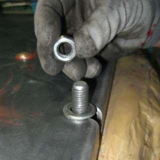
7 Positioning and mounting the boiler For ease of handling, transport and import of boiler, PelTec is delivered in parts that need be mounted on the boiler when the boiler is in the boiler room. These parts need to be installed on the boiler: - Fan - mount on the back of boiler, is obligatory to use the flange gaskets fan, fastened using M bolts and nuts. Plug-connector for power supply fan and the fan tachometer in the back of the control box. Fan output can be mounted in any directions. - Mechanism for grating cleaning - mount on the right side of the boiler ( in this side is pellet tank), must be fastened using M bolts and nuts. After assembly, it is necessary to attach the lever burner grid with gear motor trail. Plug-in two cables with connectors (motor and microswitches). - Connection tubes - mount connecting tube with -way mixing valve to the boiler so that the T-piece is in the upper side. On the upper connector of the T-piece incorporate safety ventilation group. On the back of boiler were prepared two holenders for mounting connection tubes (connection tubes with way mixing valve). Be sure to use the seal for holenders. Set return temperature sensor in the elbow with a socket for the sensor between the -way mixing valve and the boiler. It is obligatory using the included thermal paste. Plug-in return flow sensor on the back of the box control. Connect the pump cable with connector to the back of the control box. Mandatory set the pump on the speed. - Elbow with socket for the flow sensor -must necessarily be installed after -way mixing valve on the flow of the installation. Set flow sensor in the socket for sensor. It is obligatory using the included thermal paste. Plug-in return flow sensor on the back of the box control. - Motor device - set the motor device to the -way mixing valve. Plug-in the power connector on the back of the control box. - Pellet level in the tank sensor - mount this sensor on the back side inside of the pellet tank (see page 9). First set the plastic glass distance for sensor. After that, put the sensor on this glass. Attach the sensor and the plastic distance with screws supplied. Attach protective cover. Plug-in the cable with connector of the pellet level sensor on the back of the box control. - Pellet tank - mount pellet tank according installation manual for mounting pellet tank. Set up pellet transporter in the pellet tank. Place the pellet tank to the boiler and set PVC tube to conveyor and tube supply on the boiler. Set up the PVC tube so as to allow the smooth falling pellet into the burner. If necessary, cut the PVC tube to the required length. Plug-in the power connector on the back of the control box. OTE: check the tightness of connection tubes. Fasten connections binding tubes if necessary, so that a good seal.


")


8 Status of delivery, mounting parts.. MOUTIG COMPOETS Slika. Mounting components Flange for mounting on the boiler Flange for mounting on the boiler Fan (Fan output can be mounted in any directions) Mechanism for grating cleaning -way mixing valve Connection tube PelTec Connection tube PelTec - Motor device for -way mixing valve


9 Positions of mounted components Flange for mounting fan Flange for mounting mechanism for self-cleaning Protection cover Pellet level sensor Plastic pad Mounted position (be sure to attach the cable with cable ties Position of pellet tank Position of mechanism for grating cleaning The main switch Display Elbow with socket for sensor The main electronic board Electronic board inputs Connectors for pump / diverter valve Socket 9
 A.")


10 Installation of motor device... Installation of motor device (THE FIRST ASSEMBLY). Set valve clapper so that it is horizontal position (designation must be on the right side A ) A. Put clutch of motor device (designation must be on the right side B ). Set motor device on the valve as shown in gure (moving part of motor device must be in a horizontal position; Green delimiter'' C'' must be in the center of the handle slot'' D''). Set screw for fastening motor device E C D. Tighten the screw to secure the motor device (when the screw is tightened, the movable part of the device is rotated to the right down to the end position) B E. Set lever ''F'' to drive F 0. Set the designation of openness "G" on device as shown in gure G


 A. Designation position on clutch of motor device.")
11 Installation of motor device. Handle position H Position UP - Manual operation H 9. Turning the handle'' G'' so that it can be set in the DOW position - automatic operation G... ISTALLATIO OF MOTOR DEVICE (IF THE BOILER IS WORKED) If the boiler is worked motor device may be removed only when the boiler is switched off. When the boiler is switched off motor-driven closes -way mixing valve and is in the position as shown in Figure below.. Device position when the boiler is not. Valve position when the boiler is not working working (valve is closed) (valve is closed); designation on the axle'' A'' is the top right corner ( ) A. Designation position on clutch of motor device. Set the motor device as shown below before assembly, designation on the clutch (the movable part of the devicemust be turned ''B'' is at the top right ( ) so that green delimiter'' C'' is aligned with the groove of the handle'' D'' and is in the top right corner ( ) B C D

12 Installation of motor device. Tighten the screw to secure the motor device (when the screw is tightened, the movable part of the device is rotated to the right down to the end position). Set the device handle, rotate the left until it reaches the bene cial position, so that can be set in position DOW - Automatic operation.device position in the DOW position - automatically work; boiler ready for operation ow from the boiler ow in the installation return to the boiler Return from installation
13 Safety elements, fuel.. SAFETY ELEMETS Boiler have a few safety elements: - Bimetal thermostat built on the burner pellet feeding tube. If the bimetal set temperature (0 C) is exceeded, pellet feeding is stopped, the burner shuts down and the error E appears on the control unit (LED diode switches on). - If there is no flame (the built in photo-cell does not detect the flame within set time), control stops the burner operation and error E is displayed or it goes to blowing off and error E is - Displayed (LED diode switched on).control unit has a built in protective function which protects the boiler against overheating. If temperature in the boiler exceeds 9 C, regardless heating or sanitary water is needed the boiler pump and/or the sanitary water turns on and works until temperature in the boiler falls below 9 C. - The fan has a built-in RPM counter and, if regulation is informed that the fan does not operate in accordance with the requirement interrupts the process display fan error - Drive for grate linear move have in-built two switches by wich control unit monitor position of grate. If grate at given moment is not on provided place, control unit recieve information that grate is not on provided place and interrupt proces and display information about grate error. - Flue gas connection have in-built sensor for flue gas temperature meassuring. If flue gas tube temperature is over 0 C, control unit interrupt proces and display information about too high flue gas temperature. When temperature in the boiler exceeds 0 C (+0 C / - 9 C), power supply is turned off by the safety thermostat (via control unit). Thermal protection built in coils of the fan electric motor at the burner and the screw feeder motor, protects them against overheating caused by failure or locking. A flexible tube connecting the pellet burner and pellet tank is made of plastic material reinforced with metal wire which, in case of back flame from the burner to the tank, melts and prevents flame to penetrate to the pellet tank... FUEL Wood pellets are used as fuel in boilers with built-in pellet burner. Wooden pellets are bio-fuel made of wooden wastes. Pellets can be packed in different packaging: in bags ( kg or 000 kg), or as bulk in large (underground) tanks ( - m ) or in basement spaces. Recommended properties of pellets for firing in PelTec boilers are the following: - heating value >= kwh/kg ( MJ/kg) -diameter <= mm -max. moisture content <= % -max. dust content <=, %.
14 .0. BOILER POSITIOIG AD ASSEMBLY Boiler positioning, assembly and building in must be performed by a qualified person. We recommend that boiler is placed on a concrete base with height of 0 to 00 mm above the floor. Boiler room must be frostproof and well ventilated. Boiler has to be positioned so that it can be properly connected to the chimney (see Figure ) and simultaneously, enabling tending of boiler and additional equipment, control during operation, cleaning and maintenance. WARIG! Flammable items must not be placed on the boiler and within the minimum distances shown in Figure... MIIMUM DISTACE FROM THE ROOM WALLS Figure. Minimum distance from the room walls for PelTec min. 00 mm max 00 mm min. 0 mm min. 0 mm min. 00 mm - Boiler PelTec - Chimney - Flue (Chimney connection; must be insulated).. OPEIG FOR FRESH AIR (FRESH AIR SUPPLY) Each boiler room must be equipped with an opening for supply of fresh air which is dimensioned in accordance with boiler output (minimum opening area according to the below shown equation). Such opening must be protected with a net or grate. All installation works have to be performed in accordance with valid national and European standards. Boiler must not operate in flammable and explosive environment. A =,0 x Q A - opening area in cm Q - boiler output in kw
15 Connection to the chimney.0. COECTIO TO THE CHIMEY IProperly dimensioned and built chimney is the main condition for safe and economical functioning of the boiler. The thermal insulation of the chimney has to be done properly, it has to be absolutely gas-proof and smooth. On its lower part there has to be built in the opening for cleaning with the door. An brick-layed chimney has to have three layers with an insulation of 0 mm in the middle, if the chimney is built inside the house (i.e. inside the heated area), or an insulation of 0 mm if it is built outside the house (i.e. outside the heated area). The flue gas temperature has to be at least 0 C higher then the temprerature of their consdensation point. The choice and the construction of the chimney has to be performed by the authorized person. Inside dimensions of the chimney intersection selected in accordance with diagram for chimney selection, they depend of its height and of the capacity of the boiler. Chimney must be dimenensioned by "diagram for chimney selection" and maximum permetted lenght of connection flue gas tube between connection on fan and chimney is 000 mm and minimum light diameter xx0 mm with maximum two 90 bends. Connection flue gas tube can be mounted horizontally or at any angle which allows to gas, on his way to chimney, a constant increase of height with condidering of exit point from fan. Connection flue gas tube must have openings for cleaning through which is possible to clean entire lenght of flue gas tube or must ensure easy removal part of flue gas tube which allow complete cleaning of connection flue gas tube. To prevent entry of condensate form chimney into the boiler, flue gas tube must be mounted 0 mm deeper into the chimney. Connection ue gas tube between fan and chimney must be insulated with 0-0 mm mineral wool. The chimney must be resistant against flue condensate! Figure. Dimensioning of the chimney for PelTec 0 Rated thermal output of the boiler (kw) Chimney light diameter (cm) Chimney dimensioning example: for boiler Pel - Tec Boiler heat output: kw Fuel: wood pellets Required usable chimney height: m Required chimney light diameter: 0 cm Wood pellets Useful height of the chimney (m)
16 Installation, connection to central heating system.0. ISTALLATIO All local regulations, including those referring to national and European standards need to be complied with when installing the appliance... COECTIO TO CETRAL HEATIG SYSTEM All installation work must be made in accordance with valid national and European standards. Boiler PelTec can be built in closed and open central heating systems. In both cases boiler can be fired with wood chips. Installation has to be made, in according to technical standards, by a professional who will be responsible for proper boiler operation. Before connecting boiler to central heating system, the system has to be flushed to remove impurities remaining after system installation. It prevents boiler overheating, noise within the system, disturbances at a pump and mixing valve. Boiler should always be connected to central heating system by connectors, never by welding. Figure. shows safe distances required for boiler cleaning and maintenance.... COECTIO TO OPE HEATIG SYSTEM In open system it is necessary to put an open expansion vessel min. 0, m above the height of the highest heating body. If expansion vessel is located in a room without heating, it should be insulated. The system pump could be connected on the inline or back line of the boiler.... COECTIO TO CLOSED HEATIG SYSTEM In closed heating system it is obligatory to build in certified safety valve with opening pressure of, bar and a membrane expansion vessel. Safety valve and expansion vessel must be built in accordance with professional rules and between safety valve and expansion vessel and boiler must not be any valve. Schemes for possible configurations are on following pages.
17 Configuration PTV, DKG Scheme. Configuration PTV bar M P VH - Boiler PelTec - Air self-venting group, bar - Motor -ways mixing valve - Closed type expansion vessel - Return flow sensor - DHW tank - DHW sensor Scheme. Configuration DKG bar P M P - Boiler PelTec - Air self-venting group, bar - Motor -ways mixing valve - Closed type expansion vessel - Return flow sensor - Flow sensor - Heating circuit - Room thermostat
18 Configuration PTV DKG, AKU Scheme. Configuration DKG PTV 9 0 bar P P P M P VH - Boiler PelTec - Air self-venting group, bar - Motor -ways mixing valve - Closed type expansion vessel - Return flow sensor - Flow sensor - DHW tank - DHW tank sensor 9 - Heating circuit 0 - -way diverter valve - Room thermostat Scheme. Configuration AKU bar M - Boiler PelTec - Air self-venting group, bar - Motor -ways mixing valve - Closed type expansion vessel P - Back flow sensor - Accumulation tank CAS - Accumulation tank sensor CAS (upper) - Accumulation tank sensor CAS (lower)
19 Configuration PTV DKG, AKU -- IKG Scheme. Configuration PTV AKU bar P P 9 M P 0 VH - Boiler PelTec - Air self-venting group, bar - Motor -ways mixing valve - Closed type expansion vessel - Return flow sensor - DHV tank - DHV tank sensor - Accumulation tank CAS 9 - Accumulation tank sensor CAS (upper) 0 - Accumulation tank sensor CAS (lower) - -way diverter valve Scheme. Configuration AKU -- IKG 0 9 P bar M P - Boiler PelTec - Air self-venting group, bar - Motor -ways mixing valve - Closed type expansion vessel - Return flow sensor - Accumulation tank CAS - Accumulation tank sensor CAS (upper) - Accumulation tank sensor CAS (lower) 9 - -way manual mixing valve 0 - Room thermostat 9
20 Configuration PTV AKU -- IKG, AKU -- PTV Scheme. Configuration PTV AKU -- IKG P bar P P 9 M P 0 VH - Boiler PelTec - Air self-venting group, bar - Motor -ways mixing valve - Closed type expansion vessel - Return flow sensor - DHV tank - DHV tank sensor - Accumulation tank CAS 9 - Accumulation tank sensor CAS (upper) 0 - Accumulation tank sensor CAS (lower) - Heating circuit - -way diverter valve - -way manual mixing valve - Room thermostat Scheme. Configuration AKU -- PTV bar 9 P M P 0 VH - Boiler PelTec - Air self-venting group, bar - Motor -ways mixing valve - Closed type expansion vessel - Return flow sensor 0 - Accumulation tank CAS - Accumulation tank sensor CAS (upper) - Accumulation tank sensor CAS (lower) 9 - DHV tank 0 - DHV tank sensor
21 Configuration AKU -- IKG PTV, HS Scheme 9. Configuration AKU -- IKG PTV bar P M P P 9 0 VH - Boiler PelTec - Air self-venting group, bar - Motor -ways mixing valve - Closed type expansion vessel - Return flow sensor - Accumulation tank CAS - Accumulation tank sensor CAS (upper) - Accumulation tank sensor CAS (lower) 9 - DHV tank 0 - DHV tank sensor - Heating circuit - -way manual mixing valve - Room thermostat Scheme 0. Configuration HS bar M P - Boiler PelTec - Air self-venting group, bar - Motor -ways mixing valve - Closed type expansion vessel - Return flow sensor - Hydraulic crossover - Hydraulic crossover sensor


22 Electrical connections.0. ELECTRICAL COECTIOS All electrical works must be performed by a certified professional in accordance with valid national and European standards. If the supply cord is damaged, it must be replaced by the manufacturer, its service agent or similarly qualified persons in order to avoid a hazard. A device for switching of all power supply poles must be installed in electrical installation in accordance with the national regulations on electrical installations. Pump of heating system should be connected to boiler control unit PelTec. CAUTIO: When connecting any electrical part be sure to unplug the boiler at the main switch and disconnect the power supply. Figure. Connectors for power supply, el. components and sensors APAJAJE M - Pellet feeder M - Motor device for -way mixing valve M - Fan P - Heating pump P - Domestic water pump P - Tank pump S - Sanitary water sensor S - Accumulation tank sensor (up) / Hydraulic crossover sensor S - Accumulation tank sensor (down) S - Flue gas sensor S - Outside temp. sensor S - Flow sensor S - Return sensor S - PVC tube bimetal sensor S9 - Room thermostat S0 - Alarm S - Reserve S - Pellet level in the tank sensor - UTP connector PelTec, 0 PelTec -
23 , A L PE ' L M Pellet conveyor motor L Lt ' Brown L L L Lt Lt M ' Lt L L L * * Lp Lp PO W PE L T E C! i z l a z i Lt TO Lt Lt motor Flu gas tube mechanism cleaning motor for the grating self-cleaning TO F!, A Mixing valve motor device Lt Lt TO F! 0 0m A Black Blue F!, A Lt TO Lt Electric heater ' Connector -bit white ST - safety thermostat GS - Main switch * - sticker with a number on the connector ' Connector -bit white Connector -bit white Connector -bit black ' Connector -bit black Connector -bit white Electrical scheme.. ELECTRICAL SCHEME OUTPUTS
24 Electrical scheme.. ELECTRICAL SCHEME OUTPUTS L L P SI V I M UŠ K I ' L L P Z E L E I M UŠ K I P Z E L E I Ž E S K I L L P SM E ĐI Ž E S K I P SM E ĐI M UŠ K I ' Pump P P SI V I Ž E S K I Pump P P L L T T T T S S B B M P CR / S M M UŠ K I P CR / S M Ž E S K I Connector -pin green ' Connector -pin green Connector -pin grey ' Connector -pin grey Connector -pin black/brown ' Utičnica -polna crna/smeđa Connector -pin brown ' Connector -pin brown Brown ' Flue gas fan with speed senzor Black ' Pump P P Blue Yellow/Green P Red Black White
25 P CRI MUŠK I P C RI Ž E S K I ' * * Microswitches for motor mechanism for the self-cleaning ' + V P SI V I Ž ESK I P SI V I MUŠK I * * Ai Photocell S I G G D HAL Ai Code key for boiler power Ai + V RE L R o RE L PE L T E C! inputs GD UT P Presostat UT P * - sticker with a number on the connector ' Connector -bit black Connector -bit black ' Connector -bit black Connector -bit grey Boiler sensor Electrical scheme.. ELECTRICAL SCHEME IPUTS
26 Domestic water sensor Accumulation tank sensor (up) / Hydraulic crossover sensor USB Accumulation tank sensor (down) UTP P E L T E C! di s p l Flue gas sensor The ow sensor S IG G D SIG SIG G D S Return sensor GD S S SIG S IG GD SIG G D S SIG S IG GD S SIG G D S9 Room thermostat G D S P E L T E C! OSJETICI S Bimetallic thermostat G D S SIG S IG GD S +V S IG GD S Alarm sound max. 00 ma G D S0 UTP UTP G D S IG +V Pellet level in the tank sensor Electrical scheme.. ELECTRICAL SCHEME SESORS
27 Operating the system, safety, startup.0. OPERATIG THE SYSTEM Boiler must not be used in flammable and explosive environment. It must not be used by children or disabled persons (either physically or mentally), as well as by person without knowledge or experience, unless they are under control or trained by s person responsible for their safety. Children must be supervised in the vicinity of the product. If the supply cord is damaged, it must be replaced by the manufacturer, its service agent or similarly qualified... SAFETY ISTRUCTIOS FOR THE ISTALLATIO ROOM Boiler room must be frost-proof and well ventilated. Boiler has to be positioned so that it can be properly connected to the chimney (see point.0) and simultaneously, enabling tending of boiler and additional equipment, control during operation, and cleaning and maintenance.. IITIAL STARTUP See technical instructions for PelTec digital control unit where is explained initial startup. ote: The start up has to be done by the person authorized on behalf of Centrometal d.o.o. otherwise the warranty for this product is not valid and the product must not be used. ote: If condensation escapes during the initial heatup phase, this does not indicate a fault. If this occurs, clean up using a cleaning rag... FILLIG / REFILLIG PELLET TAK WITH FUEL CAUTIO: Use only permitted pellets!
28 Boiler use.. BOILER USE Boiler must not be used in flammable and explosive environment. It must not be used by children or disabled persons (either physically or mentally), as well as by person without knowledge or experience, unless they are under control or trained by s person responsible for their safety. Children must be supervised in the vicinity of the product. If the supply cord is damaged, it must be replaced by the manufacturer, its service agent or similarly qualified persons in order to avoid a hazard. Protective gloves are obligatory. Check whether boiler and equipment are installed and connected in accordance with these Technical instructions. Check whether chimney meets requirements of point.0 therein. Check whether boiler room meets all requirements therein. Check if fuel fulfils all requirements therein. Check whether the boiler and the entire heating system are filled with water and vented. ote: Before every use chech if the boiler doors and cover door are closed (Figure ). If you smell flue gas: - shut down the heating system - Ventilate the boiler room - Close all doors leading to the living space Flue gas can lead to life-threating poisoning! Slika. PelTec boiler door Flue gas tubes door Turbulators of ue gas tubes Upper boiler door Left low boiler door (Behind the door is a box of ashes) Right low boiler door (Behind the door is a box of ashes)


29 Cleaning and maintenance.0. CLEAIG AD MAITEACE Every millimeter of soot on the exchange surfaces and in the flues means about % more fuel consumption. A clean boiler saves fuel and protects the environment. Save fuel always clean the boiler in good time! Protective gloves PROTECTIVE GLOVES ARE OBLIGATORY! Protective gloves must be used! Ash remaining in boiler after solid fuel firing should be disposed into metal containers with a cover. First, main switch at boiler control unit has to be turned off. Flue gas chamber should be cleaned once at year. Fan box should be cleaned as required. Fan blades should be cleaned as required. Ash tray in the lower boiler part should be cleaned after spent kg of pellets. Checking of all control and safety elements once per year by authorised service man / fitter is recommended. Firebox should be cleaned after spent kg of pellets, depend of pellet quality., - Take out part from the firebox - Take out part from the firebox - Scrape soot from the exchange surface with scraper - Drag ash to the ash box, - Take out and empty ashboxes - Cleaning tools - scraper and brushes This actions need to be taken after fired every two tanks of the pellet! 9


30 Cleaning and maintenance.. EXTRACTIO OF TURBULATORS 9 0 A A A B B A B Procedure of extracting turbulators: B - Casing cover - Remove the casing cover - Flue outlet cover - Unscrew the screws which hold top boiler door - Remove flue outlet cover - Unscrew the lever A from the cleaning mechanism - Unscrew the screw A which hold turbulator axle with cleaning mechanism - Pull out axle A 9 - Take out turbulators A 0 -Unscrew the other lever B from the cleaning mechanism - Unscrew the screw B which hold turbulator axle with cleaning mechanism - Pull out axle B - Take out turbulators B ote: Place turbulator back in the same way but in the reverse order! 0
31 Cleaning intervals The reasons for recommending a regular, components maintenance service and the necessary maintenance intervals: Part of PelTec Ash boxes (Figure ) Cleaning of exchanging surfaces Cleaning a places over exchaning ue gas tubes (Figure ) Cleaning interval Discharge after spent kg of pellets Once a year Cleaning of pellet tank Photocell The ecological rules and standards must be applied for disposal of changed spare parts, wrapping material, all parts of the boiler after it s expire Electric heater Failure on distribution power box with digital boiler control unit Fan failure Pellet feeder Motor failure Temperature sensors failure Photocell failure Every seven years to call an authorized service provider for routine maintenance and control.
32 otes Centrometal d.o.o. shall not be responsible for possible incorrect data caused by printing errors or error made in transcription and all figures and diagrams are for explanatory purposes only and relevant adjustment have to be made at the spot. In any case, it reserves the right to modify its products as deemed to be required and useful without any prior notification. Centrometal d.o.o. Glavna, 00 Macinec, Croatia central tel: , fax: + 0 service tel: + 0, fax: servis@centrometal.hr HEATIG TECHIQUE
HEATING TECHNIQUE. Centrometal d.o.o. - Glavna 12, Macinec, Hrvatska, tel: , fax:
 HEATING TECHNIQUE Centrometal d.o.o. - Glavna, 006 Macinec, Hrvatska, tel: +8 0 7 600, fax: +8 0 7 6 TECHNICAL INSTRUCTIONS for installation, use and maintenance of hot water boiler and installation of
- 12, , TECHNICAL INSTRUCTIONS
 HEATING TECHNIQUE Centrometal d.o.o. - Glavna, Macinec, Croatia, tel: +8 7, fax: +8 7 TECHNICAL INSTRUCTIONS for installation, use and maintenance of hot water boiler and installation of additional equipment
USE AND MAINTENANCE. Cm Pelet-set (60-90 kw) TECHNICAL INSTRUCTIONS
 TECHNICAL INSTRUCTIONS") CENTROMETAL d.o.o. Glavna 12 40306 Macinec Croatia tel: +385 40 372 600; fax : +385 40 372 611 TECHNICAL INSTRUCTIONS USE AND MAINTENANCE Cm Pelet-set (60-90 kw) For boilers: EKO-CK P 70-110 TUPS-90K-09-2015-E-N-eng
CENTROMETAL d.o.o. Glavna 12 40306 Macinec Croatia tel: +385 40 372 600; fax : +385 40 372 611 TECHNICAL INSTRUCTIONS USE AND MAINTENANCE Cm Pelet-set (60-90 kw) For boilers: EKO-CK P 70-110 TUPS-90K-09-2015-E-N-eng
TECHNICAL INSTRUCTIONS USE AND MAINTENANCE
 TECHNICAL INSTRUCTIONS USE AND MAINTENANCE Cm Pelet-set For boilers CentroPlus 25/35 and CentroPlus-B 25/35 (solid fuel and wood pellets fuel firing) TUPSCP-K-11-2016-ENG CONTENTS 1.Introduction 2. Status
USE AND MAINTENANCE. Cm Pelet-set TECHNICAL INSTRUCTIONS. (14-35 kw) For boilers: EKO-CK P (EKO-CK 20-40) EKO-CKB P (EKO-CKB 20-40)
 For boilers: EKO-CK P (EKO-CK 20-40) EKO-CKB P (EKO-CKB 20-40)") TECHNICAL INSTRUCTIONS USE AND MAINTENANCE Cm Pelet-set (14-35 kw) For boilers: EKO-CK P 20-40 (EKO-CK 20-40) EKO-CKB P 20-40 (EKO-CKB 20-40) TUPS-K-02-2011-E-N-ENG CONTENTS 1. Introduction....... 2. Status
TECHNICAL INSTRUCTIONS USE AND MAINTENANCE Cm Pelet-set (14-35 kw) For boilers: EKO-CK P 20-40 (EKO-CK 20-40) EKO-CKB P 20-40 (EKO-CKB 20-40) TUPS-K-02-2011-E-N-ENG CONTENTS 1. Introduction....... 2. Status
BIO-CK P Unit TECHNICAL INSTRUCTIONS. for installation, use and maintenance of hot water boiler and installation of additional equipment
 HEATING TECHNIQUE Centrometal d.o.o. Glavna, 006 Macinec, Croatia, tel: +8 0 7 600, fax: +8 0 7 6 TECHNICAL INSTRUCTIONS for installation, use and maintenance of hot water boiler and installation of additional
Centrometal d.o.o. - Glavna 12, Macinec, Hrvatska, tel: , fax: THE BOILER PelTec 12 WITH SPARE PARTS LIST
 HEATING TECHNIQUE Centrometal d.o.o. - Glavna 12, 40306 Macinec, Hrvatska, tel: 040 372 600, fax: 040 372 611 DISPOSITIONAL (EXPANDED) VIEW OF THE BOILER PelTec 12 WITH SPARE PARTS LIST PelTec12 EPKRD-PelTec-12-01/20-ENG-euro
HEATING TECHNIQUE. Centrometal d.o.o. - Glavna 12, Macinec, Croatia, tel: , fax: C O2=8% 80 C.
 HEATING TECHNIQUE Centrometal d.o.o. - Glavna 12, 40306 Macinec, Croatia, tel: +385 40 372 600, fax: +385 40 372 611 Technical instructions using of REGULATION hot water boiler PelTec / PelTec-lambda 120
CAS; -S; -B; -BS TECHNICAL MANUAL HEATING TECHNIQUE. for instalation, use and maintenance of the water accumulation tanks
 HEATING TECHNIQUE Centrometal d.o.o. - Glavna 12, 400 Macinec, Croatia, tel: +85 40 72 00, fax: +85 40 72 11 TECHNICAL MANUAL for instalation, use and maintenance of the water accumulation tanks CAS; -S;
INSTRUCTIONS FOR USE OF COMBINED BOILER INTENDED FOR COMBUSTION OF BOTH PELLETS AND SOLID FUEL ABC COMBO
 INSTRUCTIONS FOR USE OF COMBINED BOILER INTENDED FOR COMBUSTION OF BOTH PELLETS AND SOLID FUEL ABC COMBO .Technical specifications Boiler power DESCRIPTION Water content in a boiler Required draft Supply
Cm Pelet-set (60-90 kw)
") CENTROMETAL d.o.o. Glavna 12 40306 Macinec Croatia tel: +385 40 372 600; fax : +385 40 372 611 TECHNICAL INSTRUCTIONS FOR THE COMMISSIONING AND ADJUSTMENT Cm Pelet-set (60-90 kw) For boilers: EKO-CK P
CENTROMETAL d.o.o. Glavna 12 40306 Macinec Croatia tel: +385 40 372 600; fax : +385 40 372 611 TECHNICAL INSTRUCTIONS FOR THE COMMISSIONING AND ADJUSTMENT Cm Pelet-set (60-90 kw) For boilers: EKO-CK P
CentroPelet ZV14 TECHNICAL INSTRUCTIONS HEATING TECHNIQUE. for regulation, use and maintenance of pellet stove
 HEATING TECHNIQUE Centrometal d.o.o. - Glavna 12, 40306 Macinec, Croatia, tel: +385 40 372 600, fax: +385 40 372 611 TECHNICAL INSTRUCTIONS for regulation, use and maintenance of pellet stove CentroPelet
Cm Pelet-set - touch TECHNICAL INSTRUCTIONS FOR THE COMMISSIONING AND ADJUSTMENT
 CENTROMETAL d.o.o. Glavna 12 40306 Macinec Croatia tel: +385 40 372 600; fax : +385 40 372 611 TECHNICAL INSTRUCTIONS FOR THE COMMISSIONING AND ADJUSTMENT Cm Pelet-set - touch (60-90 kw) For boilers: EKO-CK
Cm Pelet-set TECHNICAL INSTRUCTIONS FOR THE COMMISSIONING AND ADJUSTMENT. (14-35 kw) For boilers: EKO-CKB P (EKO-CKB 20-40)
 For boilers: EKO-CKB P (EKO-CKB 20-40)") TECHNICAL INSTRUCTIONS FOR THE COMMISSIONING AND ADJUSTMENT Cm Pelet-set (14-35 kw) For boilers: EKO-CK P 20-40 (EKO-CK 20-40) EKO-CKB P 20-40 (EKO-CKB 20-40) TUPS-M-11-2015-E-N-ENG CONTENTS 1. Introduction.....
TECHNICAL INSTRUCTIONS FOR THE COMMISSIONING AND ADJUSTMENT Cm Pelet-set (14-35 kw) For boilers: EKO-CK P 20-40 (EKO-CK 20-40) EKO-CKB P 20-40 (EKO-CKB 20-40) TUPS-M-11-2015-E-N-ENG CONTENTS 1. Introduction.....
USE AND MAINTENANCE. Cm Pelet-set TECHNICAL MANUAL. CENTROMETAL d.o.o. Glavna Macinec Croatia tel: ; fax :
 CENTROMETAL d.o.o. Glavna 12 40306 Macinec Croatia tel: +385 40 372 600; fax : +385 40 372 611 TECHNICAL MANUAL USE AND MAINTENANCE Cm Pelet-set TUPS-3-2008-eng-E-N CONTENT 1. Introduction.. 2. Delivery
BIOMASS BOILER ATTACK PELLET 30 AUTOMATIC PLUS
 BIOMASS BOILER ATTACK PELLET 30 AUTOMATIC PLUS W W W. A T T A C K. S K MODEL STRUC TURE OF THE AT TACK BOILERS THE NEW LINE OF ATTACK BOILERS FOR WOOD AND PELLETS 3000 000 6000 4 ATTACK FD PELLET yattack
Installation, operation and care. Pellmax UB. Burner not included Replaces:
 Installation, operation and care Burner not included 2011-11-11 ver: Replaces: Contents 11.11 otes...3 General...4 Function...4 Technical data...5 System principle Pellmax with radiator and tank-in-tank
Operating Manual PELLEMATIC PES CMP06 TO_VA6.39 Pelletronic TOUCH ENGLISH. PE 1491 EN_TO 1.0 Europe s specialist in pellet heating
 Operating Manual PELLEMATIC PES 12 56 CMP06 TO_VA6.39 Pelletronic TOUCH ENGLISH PE 1491 EN_TO 1.0 Europe s specialist in pellet heating Title: Operating manual PES 12-56 Article number: PE 1491 EN_TO 1.0
Operating manual. Pellet boiler. Orlan Pellet ISO 9001
 Operating manual Pellet boiler Orlan Pellet ISO 9001 Contens 1. Boiler s use...................................................................... 3 2. Boiler s way of working...........................................................
PELLET BURNER PV 350
 PELLET BURNER PV 350 INSTRUCTION MANUAL v1.1 1 PRODUCT DESCRIPTION...3 2 SAFETY RULES...3 3 WARNINGS...4 4 INSTALLATION INSTRUCTIONS...5 4.1 BOILER REQUIREMENTS...5 4.2 PELLET CONTAINER...6 4.3 INSTALLATION
Heating, Air Conditioning, Ventilation. Отопление-Кондиционеры-Вентиляция. MTM 8-30 kw UNIVERSAL OIL HEATER OPERATING MANUAL
 Heating, Air Conditioning, Ventilation Отопление-Кондиционеры-Вентиляция MTM 8-30 kw UNIVERSAL OIL HEATER OPERATING MANUAL 1. Usage MTM 8-30 universal oil heater is designed for heating commercial rooms
OPERATION MANUAL RK-2006LPP AUGER FITTED SOLID FUEL BOILER TEMPERATURE CONTROLLER. Version DC19
 OPERATION MANUAL RK-2006LPP AUGER FITTED SOLID FUEL BOILER TEMPERATURE CONTROLLER Version DC19 1. Application. Controller RK-2006LPP is designed for temperature control of solid fuel fired water boilers
Combined boiler. for solid fuel and pellets
 Combined boiler ATTACK WOOD&PELLET for solid fuel and pellets W W W. A T T A C K. S K MODEL STRUC TURE OF THE AT TACK BOILERS THE NEW LINE OF ATTACK BOILERS FOR WOOD AND PELLETS 3000 000 6000 4 ATTACK
INSTALLATION AND OPERATING INSTRUCTIONS. Ariterm 60+
 INSTALLATION AND OPERATING INSTRUCTIONS Ariterm 60+ CONTENTS General.... 2 Installation.... 4-5 Installation of temperature limit valve... 6 Measurements and connections... 7 Technical specifications and
PELLETS BURNER 15-60kW MOC
 PELLETS BURNER 15-60kW MOC. Please read those documentation before first start up the unit. Improper burner start may lead to its damage and may create a danger for end user! Table of Contents: 1. Admission
INSTALLATION, OPERATION AND MAINTENANCE. Ariterm Vedo
 INSTALLATION, OPERATION AND MAINTENANCE Ariterm Vedo CONTENTS General...3 Installation...4-5 Laddomat 21 Connection diagram...6 Temperature control valve...7 About burning wood...8 Operation...9-11 Service
Installation Instructions T 9822 Gas Dryer. en - US, CA. To prevent accidents
 Installation Instructions T 9822 Gas Dryer To prevent accidents en - US, CA and appliance damage read these instructions before installation or use. M.-Nr. 07 431 110 2 WARNING For your safety the information
IDE 20 / IDE 30 / IDE 50 IDE 60 / IDE 80
 IDE 20 / IDE 30 / IDE 50 IDE 60 / IDE 80 EN OPERATING MANUAL OIL HEATER TRT-BA-IDE20-30-50-60-80-TC-001-EN Table of contents Information on the use of this manual... 1 Scope of delivery... 1 General safety...
VETO CLEANER 500 FLUE GAS CLEANER
 As of serial number 3100 0001 VETO CLEANER 500 FLUE GAS CLEANER USER MANUAL SPARE PARTS LIST Manufacturer: ALA TALKKARI Veljekset Ala-Talkkari Oy FI-62130 HELLANMAA TEL. +358 6 433 6333 FAX +358 6 437
HG 675 CX 60 HG 675 CN 60 HG 675 CW 60
 HG 675 X 60 HG 675 CX 60 HG 675 CN 60 HG 675 CW 60 1 2 1. : 93/68: 90/396: 2006/95/CE: 2004/108/CE: - 1935/2004:. 2002/95/CE: RoHS 2.,.,,,,...,. (,..)..,,.,. ( ),,, ;,,.,.....,.,,,,,,...,. (..),,.,..,.,,,,
SOUND-INSULATED FAN. Iso-K OPERATION MANUAL. Iso-K_v.1(2)-EN.indd :20:59
-EN.indd :20:59") SOUND-INSULATED FAN OPERATION MANUAL _v.1(2)-en.indd 1 10.08.2015 15:20:59 CONTENT Introduction 3 General 3 Safety rules 3 Transport and storage requirements 3 Manufacturer's warranty 3 Fan design 4 Delivery
SOUND-INSULATED FAN OPERATION MANUAL _v.1(2)-en.indd 1 10.08.2015 15:20:59 CONTENT Introduction 3 General 3 Safety rules 3 Transport and storage requirements 3 Manufacturer's warranty 3 Fan design 4 Delivery
PELET SUCTION SYSTEM CVT. Technical manual HEATING TECHNIQUE. CentroPlus(-B) + Cm Pelet set, BioTec Plus. for the installation, use and maintenance
 + Cm Pelet set, BioTec Plus. for the installation, use and maintenance") HEATING TECHNIQUE Centrometal d.o.o. - Glavna 2, 40306 Macinec, Croatia, tel: +385 40 372 600, fax: +385 40 372 6 Technical manual for the installation, use and maintenance PELET SUCTION SYSTEM CVT configuration:
HEATING TECHNIQUE Centrometal d.o.o. - Glavna 2, 40306 Macinec, Croatia, tel: +385 40 372 600, fax: +385 40 372 6 Technical manual for the installation, use and maintenance PELET SUCTION SYSTEM CVT configuration:
HEATING TECHNIQUE PRODUCT CATALOGUE
 HEATING TECHNIQUE PRODUCT CATALOGUE about us Dear Colleagues, dear present and future users of our products A high quality product, effective use of the energy, protection of the environment and very satisfied
Operation and maintenance manual for the. KSP Spark. series boilers equipped with feeders
 Operation and maintenance manual for the KSP Spark series boilers equipped with feeders Thank you for purchasing PEREKO heating boiler. This documentation applies to the KSP Pelet boilers with fuel feeder
INSTRUCTIONS MANUAL FOR USE AND MAINTENANCE
 INSTRUCTIONS MANUAL FOR USE AND MAINTENANCE Carbel models: C-60 Plus C-70 Plus C-80 Plus C-100 Plus C-70 Plus Double-sided C-80 Plus Double-sided C-100 Plus Double-sided CARBEL C/ Ciudad de Cartagena,
Mikrofill Ethos Condensing combination boiler. Maintenance Instructions 24cc
 Mikrofill Ethos Condensing combination boiler Maintenance Instructions 24cc IMPORTANT Benchmark Installation, Commissioning and Service Record Log Book is enclosed in your customer information pack. This
Electronic Pellet Burner Controller NPBC-V3M
 Electronic Pellet Burner Controller NPBC-V3M SOFTWARE VERSION 3.3a/3.2 page of 27 CHANGES IN THE USER MANUAL OR IN THE CONTROLLER'S SOFTWARE Version of the user manual Changes Page 2.2. The software version
Installation and maintenance instructions
 6304 4995 0/004 GB For installer Installation and maintenance instructions Flue gas heat exchanger WT50/60 Please read thoroughly prior to installation and maintenance. Summary About this manual This equipment
Operating Instructions
 Operating Instructions P4 Pellet 8-60 Read and follow the operating instructions and safety information. Subject to technical change. July 2009 Fröling Heizkessel- und Behälterbau Ges.m.b.H, Industriestrasse
Installer manual AG-AA10. Air/air heat pump IHB GB AG-AA10-30 AG-AA10-40/50
 -30 Installer manual Air/air heat pump -40/50 IHB GB 1516-1 331554 Table of Contents 1 Important information 2 5 Installation 7 Safety information 2 Model combinations 7 Read before starting the installation
MANUAL. Page 1/44
 MANUAL FOR INSTALLATION AND OPERATION OF A HEATING SYSTEM, CONSISTING OF HOT WATER WOOD PELLET BOILER FROM SERIES PELLETHERM V4 AND AUTOMATED WOOD PELLET BURNER FROM SERIES GP IV http:// www.greenecotherm.eu
INDEX RECOMMENDATIONS AND SUGGESTIONS... 4 CHARACTERISTICS... 5 INSTALLATION... 6 USE... 9 MAINTENANCE... 11
 INDEX EN RECOMMENDATIONS AND SUGGESTIONS... 4 CHARACTERISTICS... 5 INSTALLATION... 6 USE... 9 MAINTENANCE... 11 2 RECOMMENDATIONS AND SUGGESTIONS The Instructions for Use apply to several versions of this
READ AND SAVE THESE INSTRUCTIONS
 READ AND SAVE THESE INSTRUCTIONS WARNING TO REDUCE THE RISK OF FIRE, ELECTRIC SHOCK, OR INJURY TO PERSONS, OBSERVE THE FOLLOWING: 1. Use this unit only in the manner intended by the manufacturer. If you
Solid fuel hot water boiler TKH KW INSTRUCTIONS MANUAL for usage and maintenance
 Solid fuel hot water boiler TKH 250-400 KW INSTRUCTIONS MANUAL for usage and maintenance Prhovacka bb 22310 Simanovci, Srbija Tel/Fax. +381 22 480404 +381 63 259422 oce@termomont.rs www.termomont.rs April
PC 640 GB. Built-in cooking tables 60 Instructions for installation and use
 PC 640 GB Built-in cooking tables 60 Instructions for installation and use Congratualtions on choosing an Ariston appliance, which you will find is dependable and easy to use. We recommend that you read
RIELLO 40 GS/M SERIES
 The Riello 40 GS/M series of two stage progressive or modulating gas burners, is a complete range of products developed to respond to any request of gas burners for hot air generator according to EN 1020.
Product range Code HE1 Connection and energy management compact unit without anti-condensation valve
 Connection and energy management compact unit 2850 series ACCREDITED CALEFFI 01259/14 GB ISO 9001 FM 21654 ISO 9001 No. 0003 Function The connection and energy management compact unit enables combining
The warranty card and conditions are effective only in the area of Poland.
 Rapa Sp. J. The warranty card and conditions are effective only in the area of Poland. The package should be removed according to the regulations of environmental protection. RAPA S. Międlar W. i I. Szymańscy
Wind. Service instruction
 Wind Service instruction E BAUBERG Company is happy to offer your attention the window axial Blauberg Wind fan. The solid team of high-qualified professionals with many years of working experience, technological
EN Instruction on mounting and use
 EN Instruction on mounting and use EN - Instruction on mounting and use Closely follow the instructions set out in this manual. All responsibility, for any eventual inconveniences, damages or fires
Easyfire Standalone biomass pellet boiler
 Easyfire Standalone biomass pellet boiler DESIGN Essential and pleasant AESTETIC, small size If the humanity is in balance with the resources of nature, the respect for the environment will be possible.
Electronic Pellet Burner Controller NPBC-V3-1
 Electronic Pellet Burner Controller NPBC-V3- SOFTWARE VERSION 3.2/3. page of 3 CHANGES IN THE TECHNICAL AND USER GUIDE OR IN THE SOFTWARE VERSION Technical and User Guide's version Changes Page 2.8. The
Installation instructions for the T 9820 Gas Dryer
 Installation instructions for the T 9820 Gas Dryer The T 9820 gas dryer is only approved for use in the USA and Canada. It is not approved for use in Mexico. To prevent accidents en - US, CA and machine
OPERATING INSTRUCTIONS with safety features
 Solid fuel boiler TKK3 with wood pellet burner TERMEC 70-90 KW OPERATING INSTRUCTIONS with safety features Prhova ka bb 22310 imanovci, Srbija Tel/Fax. +381 22 480404 +381 63 259422 oce@termomont.rs www.termomont.rs
DH-Direct Fired Poultry Farm Diesel Heater
 DH-Direct Fired Poultry Farm Diesel Heater Comparison of Diesel Heater to Gas Heater Diesel LPG Gas LPG Gas KW 43 70 120 Fuel consumption/hr 3 5.1 8.8 Heat output 37000 60000 100000 Cost of fuel/lit or
Main components. Buying all components from same manufacturer or reseller it guarantees better compatible and service if something happens
 Main components The bigger the need of heat output is. the bigger the components (storage. boiler. chimney etc.) In private houses the output need of the boiler is about 25 40 kw and in farms from 60 kw-
Installation and service must be provided by a qualified installer, service agency or the gas supplier.
 INSTALLATION AND OPERATION GUIDE FOR OLDE WORLD BASKET Vented Decorative Appliance For all models tested through PFS Corporation, to ANSI Z21.60-2003/CGA 2.26-2003, Decorative Appliance for Installation
INTRODUCTION THIS MANUAL INCLUDES IMPORTANT SAFETY INFORMATION
 INSTALLATION AND OPERATING INSTRUCTIONS FOR THE HARDY Fuel Oil Furnace Models D-140 & D-350 HARDY MANUFACTURING COMPANY, INC. 12345 ROAD 505 PHILADELPHIA, MS 39350 PHONE: (601) 656-5866 FAX: (601) 656-4559
USERS MANUAL FOR GAS BOILERS
 USERS MANUAL FOR GAS BOILERS PLEASE READ THE MANUAL CAREFULLY: IT CONTAINS IMPORTANT INFORMATION REGARDING SAFETY, INSTALLATION, USE AND MAINTENANCE OF THE APPLIANCE MODELS: NOVADENS 24 NOVADENS 24C NOVADENS
PELMAX HEATING BOILER FOR SOLID FUEL
 PELMAX HEATING BOILER FOR SOLID FUEL INSTALLATION, SERVICE AND MAINTENANCE MANUAL OF THE BOILER Member of the NIBE Group 21683 Issue 06.2012 Changes reserved Installation, service and maintenance manual
INSTALLATION, OPERATION AND MAINTENANCE. Ariterm Hybrid 20
 INSTALLATION, OPERATION AND MAINTENANCE Ariterm Hybrid 20 TABLE OF CONTENTS General...3 Installation... 4-5 Dimensions - with flue gas exhauster...6 Dimensions - without flue gas exhauster...7 Pipe installations...8
Installation & Manual. Model T-25
 Installation & Manual TR Central Heating Stove With Solid Fuel Model T-25 Tested according to DIN EN 13240 For product efficiency and emission values, see the declaration of conformity! TABLE OF CONTENTS
RL/1 SERIES. One Stage Light Oil Burners FIRING RATES LIGHT OIL RL 34/1 MZ kw
 The RL/1 burners series covers a firing range from 107 to 398 kw, and it has been designed for use in low or medium temperature hot water boilers, hot air or steam boilers, diathermic oil boilers. Optimisation
Instructions Manual SHC520X - SHC700X
 Instructions Manual SHC520X - SHC700X INDEX EN RECOMMENDATIONS AND SUGGESTIONS... 3 CHARACTERISTICS... 4 INSTALLATION... 5 USE... 7 MAINTENANCE... 8 2 RECOMMENDATIONS AND SUGGESTIONS The Instructions for
Service Manual. Unit: Pellet burner. Type: ROT-POWER. Models: kw, kw
 Service Manual Unit: Pellet burner Type: ROT-POWER Models: 15-70 kw, 20-100 kw BTI GUMKOWSKI Sp. z o.o. Sp. k. ul. Obornicka 71, 62-002Suchy Las Phone +48 606-936-692, +48 61-811-70-37 biuro@kipi.pl update:
ecomax 200 W Boiler regulator FOR SOLID FUEL BOILERS WITH A FAN OPERATION AND MAINTENANCE MANUAL ISSUE:
 Boiler regulator ecomax 200 W FOR SOLID FUEL BOILERS WITH A FAN OPERATION AND MAINTENANCE MANUAL ISSUE: 1.3 APPLICABLE TO SOFTWARE 10.034 10.035 10.036 2010-04-14 TABLE OF CONTENTS 1 Safety... 4 2 General
Operating and installation instructions for Fire Lotus H586
 Operating and installation instructions for Fire Lotus H586 Version 1, 24 May 2016 Introduction Congratulations on your new Lotus Fire. We hope and believe that it will give you many hours of warmth.
OPERATING & MAINTENANCE MANUAL INDUSTRIAL DIRECT FIRED DIESEL/KEROSENE HEATERS IC 25
 OPERATING & MAINTENANCE MANUAL INDUSTRIAL DIRECT FIRED DIESEL/KEROSENE HEATERS IC 25 NOT FOR DOMESTIC USE SPACE HEATING ONLY Made By: Spitwater Australia Pty Ltd 953 Metry St North Albury, NSW, Australia
USER S MANUAL LINCOLN PF Manufactured by: Planika Sp. z o.o. ul. Bydgoska Brzoza Poland
 USER S MANUAL LINCOLN PF-0917-0075-000 Manufactured by: Planika Sp. z o.o. ul. Bydgoska 38 86-061 Brzoza Poland Edition i1266#00 as of 25.04.2017 Serial number greater than P5660 17 IT IS OBLIGATORY TO
V-ZUG Ltd. Range hood. Levante. Operating instructions
 V-ZUG Ltd Range hood Levante Operating instructions Thank you for choosing to buy one of our products. Your appliance is made to high standards and is easy to use. Nevertheless, please take the time to
Remeha. Fuel oil/gas boilers P 520. Installation and Service Manual A
 Remeha Fuel oil/gas boilers EN Installation and Service Manual 300016859-001-A 63115 Declaration of conformity The appliance complies with the standard model described in declaration of compliance. It
Gasification boiler PYROLYT INSTRUCTION MANUAL. ver. 1.1
 Gasification boiler PYROLYT INSTRUCTION MANUAL ver. 1.1 THERMOSTAHL would like to thank and congratulate you on your purchasing this boiler device and ensure that you have made a good choice. PYROLYT boiler
Gas Instantaneous Water Heater
 6 720 607 823 GB (06.06) SM Installation and Operating Instructions Gas Instantaneous Water Heater WR10..B... WR11..B... With electronic ignition and triple safety system consisting of ionisation detector,
Heating with log wood
 English Heating with log wood De Luxe 18-40 Lambda 18-40 1 Competence is our success... HERZ FACTS: 60 subsidiaries Group headquarter in Austria Research & development in Austria Austrian owner 2.600 employees
π H-2549 SANITAIRE UPRIGHT VACUUM SAFETY uline.com
 π H-2549 SANITAIRE UPRIGHT VACUUM 1-800-295-5510 uline.com SAFETY PAGE 1 OF 5 NOTE: When using an electrical appliance, basic precautions should always be followed, including the following: READ ALL INSTRUCTIONS
Conversion Instructions Logano G234X. Gas boiler. Please read carefully before installing and servicing. Gas boiler
 Gas boiler UPON COMPLETION OF THE INSTALLATION THE INSTALLER MUST INSTRUCT THE OWNER AND OPERATOR ON THE FUNCTIONALITY AND THE PROPER OPERATION OF THE BOILER AND THE HEATING SYSTEM. INSTALLER MUST REVIEW
WOOD PELLET BURNER WITH BOILER CONTROL UNIT FOR MONTING ON BOILER CPPL-200 inv, CPPL-300 inv, CPPL-350 inv
 TECHNICAL INSTRUCTIONS FOR USE, COMMISSIONING AND ADJUSTMENT WOOD PELLET BURNER WITH BOILER CONTROL UNIT FOR MONTING ON BOILER CPPL-200 inv, CPPL-300 inv, CPPL-350 inv TUPST-M-10-2014-ENG CONTENTS 1. Introduction.
So old fashioned... As the combustion chamber is completely room sealed, it does not release any smells and does not dirty.
 ARREDO E BENESSERE So old fashioned... An intelligent choice When on a cold winters night the warm glowing flames of the KALDUS boiler are there to welcome you back home, you will be pleased that you decided
Wood logs boiler with a gasication eect IGNIS KW. INSTRUCTIONS MANUAL for usage and maintenance
 Wood logs boiler with a gasication eect IGNIS 20-40 KW INSTRUCTIONS MANUAL for usage and maintenance Prhovacka bb 22310 Simanovci, Srbija Tel/Fax. +381 22 480404 +381 63 259422 oce@termomont.rs www.termomont.rs
Operation and maintenance manual for the boilers with feeder. Q-Per
 Operation and maintenance manual for the boilers with feeder Q-Per Thank you for purchasing PEREKO boiler. This technical documentation applies to feeder boilers from the Q-PER series and contains all
Operating Instructions Manual Janfire NH/Integral Pellets Burner with External Auger
 Operating Instructions Manual Janfire NH/Integral Pellets Burner with External Auger 11899008 R1 EN Janfire 2008 Due to constant development, Janfire AB reserves the right to change part or parts of this
SWEBO Bioenergy Manual pellet burner PB50 Rev no. Date Page PBM1: (37) Installation and maintenance instructions
 Installation and maintenance instructions") PBM1:12 2008-10-16 1 (37) Installation and maintenance instructions PBM1:12 2008-10-16 2 (37) TABLE OF CONTENTS 1 GENERAL INFORMATION... 5 1.1 PELLET STORAGE... 6 1.2 CONSTRUCTION AND FUNCTION... 7 1.2.1
PBM1:12 2008-10-16 1 (37) Installation and maintenance instructions PBM1:12 2008-10-16 2 (37) TABLE OF CONTENTS 1 GENERAL INFORMATION... 5 1.1 PELLET STORAGE... 6 1.2 CONSTRUCTION AND FUNCTION... 7 1.2.1
INSTALLATION AND OPERATING INSTRUCTIONS BIOCLASS HM
 INSTALLATION AND OPERATING INSTRUCTIONS BIOCLASS HM Thank you for choosing a DOMUSA TEKNIK heating boiler. Within the product range offered by DOMUSA TEKNIK you have chosen BioClass HM model. With a suitable
USER MANUAL 9kW LILLY PELLET STOVE
 USER MANUAL 9kW LILLY PELLET STOVE Table of Contents.Overview of Stove Parts... 2.Technical Characteristics... 3 3.Important Information... 4 4.Pellet Specification...5 5.Technology... 6 6.Installation...
Light oil burners. One stage operation
 Installation, use and maintenance instructions Light oil burners One stage operation CODE MODEL TYPE 3505 RDB CF 38 50 T3 350050 RDBR CF 6 50 TR 35050 RDBR CF 33 50 TR 35050 RDBR CF 38 50 T3R 350650 RDBR
LEIHDC70SC - LEIHDC70BB LEIHDC70BC. Instructions Manual.
 LEIHDC70SC - LEIHDC70BB LEIHDC70BC Instructions Manual www.rangemaster.co.uk INDEX EN RECOMMENDATIONS AND SUGGESTIONS...3 CHARACTERISTICS...4 INSTALLATION...5 USE...8 MAINTENANCE...9 2 RECOMMENDATIONS
ARITERM OY. Arimatic 500. User manual
 ARITERM OY Arimatic 500 User manual Table of contents 1. General information... 3 2. Transport, storage and package opening... 3 3. Warranty... 3 4. Installation and commissioning... 4 5. System description...
KKKKKKKCOOKER HOOD INSTRUCTION MANUAL
 KKKKKKKCOOKER HOOD INSTRUCTION MANUAL Read this manual carefully before operation Pictures in this manual are for reference only, the product in kind prevail. E60MEW2M19 Contents 01 02 03 04 05 06 07 08
INSTRUCTION MANUAL FOR OIL BURNER MODELS
 INSTRUCTION MANUAL FOR OIL BURNER MODELS X500 Bio B10 E90-803-001-001-00 Rev 7-1 - Contents Technical specifications Technical data... 3 Working field... 3 Dimensions... 4 Head and electrode settings...
INSTRUCTION MANUAL FOR OIL BURNER MODELS
 INSTRUCTION MANUAL FOR OIL BURNER MODELS X400 Bio B10 E90-803-001-001-03 Rev 13-1 - Contents Technical specifications Technical data... 3 Working field... 3 Dimensions... 4 Head and electrode settings...
INSTRUCTION MANUAL & SERVICE MANUAL ORLIGNO 400
 INSTRUCTION MANUAL & SERVICE MANUAL ORLIGNO 400 Content 1. Delivery......................................................................... 3 2. Installation and assembly.........................................................
Air-Water heat pump Small GT
 Catalogue No.... KJ... Production date... Installation and operation manual Air-Water heat pump Small GT The heat pump generates DHW at a maximum temperature of 50 C Distributor: ver. 21/04/2015 Please
WOOD CHIP/PELLETS HEATING SYSTEMS
 WOOD CHIP/PELLETS HEATING SYSTEMS EKO-CKS Multi Plus 170-580 kw HEATING TECHNIQUE 07/2018 SHORT DESCRIPTION: Hotwater steel boilers EKO CKS Multi Plus are designed for burning wood chips P16A/B-P45A,M35
Remove the Testing Certificate from inside the combustion chamber and keep together with the instructions manual.
 Remove the Testing Certificate from inside the combustion chamber and keep together with the instructions manual. The package of the 2R GT OF boiler contains instructions for installation, operation and
Servicing manual. Wall-mounted condensing gas boiler 600 Series - 11S / 19S / 24S / 24C /2002 GB(EN) For trade use
 For trade use") GB122 7210 1300-12/2002 GB(EN) For trade use Servicing manual Wall-mounted condensing gas boiler 600 Series - 11S / 19S / 24S / 24C Please read thoroughly before attempting to diagnose fault List of contents
GB122 7210 1300-12/2002 GB(EN) For trade use Servicing manual Wall-mounted condensing gas boiler 600 Series - 11S / 19S / 24S / 24C Please read thoroughly before attempting to diagnose fault List of contents
Wall hung combination boilers. This is a CAT II2H3+ appliance USER, INSTALLATION AND SERVICING INSTRUCTIONS SUPPORTED BY
 Wall hung combination boilers This is a CAT II2H3+ appliance SUPPORTED BY USER, INSTALLATION AND SERVICING INSTRUCTIONS Index Introduction... 3 User instructions...3 Introduction... 4 Controls and lighting...
Assembly- and User Manual Electric Infrared- Patio Heater MODEL: Geda HS - 2 kw Art. Nr. HS 10000
 Assembly- and User Manual Electric Infrared- Patio Heater MODEL: Geda HS - 2 kw Art. Nr. HS 10000 Seite 1 Intended Use The patio heater is exclusively designed for heating outdoor and indoor areas such
Servicing manual. 600 Series - 11S / 19S / 24S / 24C. Wall-mounted condensing gas boiler. For trade use
 GB122 Servicing manual Wall-mounted condensing gas boiler 600 Series - 11S / 19S / 24S / 24C For trade use Please read thoroughly before attemting to diagnose fault 7217 4900 (03/2010) GB/IE List of contents
KITURAMI Wood PELLET BOILER. User s Manual - KRP-20A
 Pellet KITURAMI Wood PELLET BOILER User s Manual - KRP-20A Make sure to keep the user s manual in the vicinity of the boiler, after reading it. KITURAMI Wood Pellet Boiler The user s manual describes the
Installation manual. Tumble dryers T4130. Compass Control
 Installation manual Tumble dryers T4130 Type N1130 Compass Control Installation manual in original language 487 05 41 61/EN 2011.09.16 Contents 3 Contents Safety precautions... 5 Technical data... 7 Setup...