AQUAS POOL PACKAGE INSTALLATION INSTRUCTIONS FOR MODELS: XPN AQUAS Pool Package
|
|
|
- Cory Ryan
- 5 years ago
- Views:
Transcription

1 AQUAS POOL PACKAGE INSTALLATION INSTRUCTIONS FOR MODELS: XPN AQUAS Pool Package The AQUAS pool package system is a high efficiency commercial condensing boiler, pre-piped package system from the factory to an indirect heat exchanger. This pool heater is a low temperature operating system designed to take advantage of the stainless steel heat exchanger and condensing operating temperatures to ensure the highest efficiency possible. The AQUAS is designed around a predetermined flow set by the manufacturer between the boiler and the indirect heat exchanger. The AQUAS operates off the pool system pump itself which will continually supply water to the indirect heat exchanger. This means there is no need to purchase a dedicated circulator to deliver water to this package system. Installation Instructions To achieve the optimum operating efficiency of your AQUAS it is recommended that you keep the pool water flow of each appliance within plus or minus five gallons per minute of the recommended flow as stated in Table A. Low flow through the indirect heat exchanger will result in elevated temperatures supplied to the pool. MODEL TABLE A RECOMMENDED SYSTEM WATER FLOW CONNECTION SIZE GPM 2.5" GPM 2.5" GPM 2.5" GPM 3" GPM 3" RECOMMENDED CLEARANCES: BOILER - SEE KNIGHT XL I & O MANUAL INDIRECT HEX - ALLOW 18" FOR SERVICE ON ALL SIDES Piping Pool / spa connections to the indirect heat exchanger are SCH 80 CPVC glue fittings. The connections from the field loop to the heat exchanger are to be done in CPVC pipe as follows: Use cement on the connections so they are rated for CPVC pipe and have enough body to hold the connection. To make the connection, apply glue to both the CPVC flange and the section of pipe. Insert the pipe into the flange until it reaches the bottom of the flange. Turn the pipe a half turn in the socket to ensure that a proper seal is made. Pool water is designed to flow from right to left standing in front of the boiler (factory installed sensor is on the inlet side of the indirect heat exchanger, see FIG. 8). The supply and return water piping to the indirect heat exchanger shall be no smaller than 2.5" for models and 3" for models Throttling Valve A T of 8-10 F across the indirect heat exchanger is recommended. Throttling valves are used to set the flow through the indirect heat exchanger (standard gate valves are acceptable). FIG. 1_Component Location Gas Inlet Air Inlet Connection Flue Connection Pressure Reducing Valve / Auto Fill Valve System Sensor Location Cupro-Nickel Pool Heat Exchanger Skid Mounted on Steel Frame Flow Switch Boiler Pump 399,000 to 800,000 BTUs Expansion Tank Condensate Drain Relief Valve T&P Gauge
2 The system can be installed in either a Full Flow or Diverted Flow orientation: Full Flow (reference FIG. 6) If the total system flow of the swimming pool or spa system is within five gallons per minute of the recommended system water flow as shown in Table A on page 1, this type of system is recommended. Diverted Flow (reference FIG. s 7 & 8) Criteria for installing a diverted flow system is as follows: If the total system flow is greater than the amount required by the indirect heat exchanger. Installations with temperatures in excess of 95 F. This is necessary so the pool high limit will not trip. No water should enter the pool / spa in excess of 110 F. If the heat exchanger pool outlet is in excess of 110 F the water must be tempered down. Multiple unit installation. Example: Total system flow is 500 gallons per minute (GPM). If two AQUAS Pool Packages (800,000 Btu/hr) were installed, each of the pool packages would require 202 GPM for a total of 404 GPM of the pool water being diverted through the indirect heat exchangers while the other 96 GPM would be diverted back to the pool. Apply a small amount of a high quality RTV silicone sealant to the threads to prevent leaks and install the limit and bulbwell into the threaded opening in the pipe. Install the limit control and bulbwell and tighten to seal. Do not over tighten either part into the threaded opening in the PVC pipe. Over tightening can damage the parts and/or strip the threads cut into the plastic pipe. Wire the 110 F limit into the pool heater control circuit as shown in FIG. 2 on page 3. If additional wire length is needed, use 18 gauge wire for distances up to 30 feet. For longer distances, size the wire per Table B. TABLE B Remote Wire Connection WIRE GAUGE MAXIMUM ALLOWABLE LENGTH 12 GA 100 ft. 14 GA 75 ft. 16 GA 50 ft. 18 GA 30 ft. Auxiliary Mixed Water Limit Control Ensure that the auxiliary 110 F mixed water limit control is installed in the filter system piping. Install the auxiliary limit a minimum of three feet downstream from the point where the heated water from the indirect heat exchanger is added to the filtration system (see FIG. s 6-8). If the water leaving the heat exchanger is in excess of 110 F a bypass must be installed to temper the water below 110 F before re-entering the pool/spa. The limit will be mounted in a 3/8" NPT tapped fitting installed in the filtration system piping or it may be installed directly into a tapped opening in the PVC filter system piping. Turn off the filter system pump when installing the auxiliary limit in the filtration system piping. Tapped openings can be added to the PVC pipe by first drilling 9/16" pilot holes in the PVC pipe at least three feet downstream of the point where the heated water from the indirect heat exchanger is added to the filter piping. The drilled pilot holes can now be carefully threaded with a 3/8" NPT tap. After the pipe threads have been cut into the PVC pipe wall the limit and bulbwell can be inserted into the tapped openings. 2

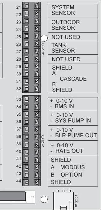
3 FIG. 2_Low Voltage Connections 3
. FIG.")

4 Indirect Heat Exchanger Installation Instructions Heat exchangers should be installed downstream of the pumping and filtration equipment (reference FIG. 3). FIG. 3_Pumping and Filtration Equipment CHLORINATOR (DOWNSTREAM) TO POOL TOP VIEW FROM POOL SYSTEM PUMP FILTRATION Pool Water Chemistry It is essential that the instructions in this section along with the Ryznar Stability Index and/or Calcium Stability Index are followed to prevent corrosion / erosion of the indirect heat exchanger: - Always keep ph to within correct levels. The ideal pool ph should be kept to within 7.4 to Under no circumstances should the ph fall below 7.2 or rise above 7.8 (see FIG. 4). Check on a day-to-day basis. Alter pool condition as necessary. - Ensure that chlorine levels are within the range recommended by the chemical manufacturer and are in accordance with the type of pool, for example; private, hotel, school or municipal. - If a bypass is fitted to the indirect heat exchanger circuit, it is essential that any or all of the valves are correctly positioned to allow the recommended pool water flow to pass through the heat exchanger. - The system filter unit should be checked regularly, especially sand filters (to detect sand and diatomaceous earth). Sand filters, if working incorrectly, can allow sand to pass around the pool circuit causing erosion of the pipework and heat exchanger. Keep the pool free from debris such as leaves, grass cuttings, etc. This foreign matter can cause decay and increase ph. - It is essential that the correct amount of chlorine dosage is added to the pool. To allow proper dispersion of the dose in the pool water, distribute the chemicals to various areas of the pool. Do not dose in one area only, as this will create high acidic areas which can cause corrosion / erosion of the pool equipment. - Chlorinator should be installed downstream of the AQUAS. Filling the System The boiler is filled through the pressure reducing auto-fill valve. The operating pressure of this system is 15 psi between the heater and the indirect heat exchanger. There are no adjustments necessary to the fill valve cartridge (factory set). The expansion tank is set at 20 psi. It is necessary to check the pressure of the expansion tank when annual maintenance is performed. The boiler system operates off a city or potable water system which feeds a closed loop system. A hard line is piped from the potable water supply to the pressure reducing valve. This water is to remain on at all times when the system is in operation. Pressure Reducing Valve The valve is equipped with a fast-fill feature that can be used to override normal operation when filling and purging the system. To activate fast-fill, push and hold down the fast-fill knob on top of the cartridge as shown in FIG. 5. Relieve air from the system through operation of the pressure relief valve by pulling the lever on top of the valve, causing it to open. FIG. 5_Pressure Reducing Auto-Fill Valve PUSH CAP DOWN TO ACTIVATE FAST FILL FIG. 4_pH Scale
5 FIG. 6_Full Flow Please note that these illustrations are meant to show system piping concept only, the installer is responsible for all equipment and detailing required by local codes. FIG. 7_Bypass (if flow is greater than required by heat exchanger) VALVE THROTTLING RECOMMENDED ISOLATION VALVE FLOWSWITCH TEMPERATURE AND PRESSURE GAUGE RELIEF VALVE Adjust valves to provide suggested flow per Table A on page 1. Please note that these illustrations are meant to show system piping concept only, the installer is responsible for all equipment and detailing required by local codes. System flow should always remain higher than the required flow for the boiler(s) when the boiler(s) is in operation to prevent short cycling and high limit issues. 5

6 FIG. 8_Bypass Multiple Units (if flow is greater than required by heat exchanger) FROM POOL VALVE THROTTLING (3X) TO POOL 110 F LIMIT FOR EACH BOILER FLOWMETER (3X) (OPTIONAL) CPVC PIPING RECOMMENDED ISOLATION VALVE FACTORY POOL RETURN SENSOR LOCATION Please note that these illustrations are meant to show system piping concept only, the installer is responsible for all equipment and detailing required by local codes. System flow should always remain higher than the required flow for the boiler(s) when the boiler(s) is in operation to prevent short cycling and high limit issues. 6
7 Cascade When multiple boilers are installed, they can be wired together in a cascade sequence. A maximum of eight boilers can be controlled from a single control. In this application one boiler would be designated as the Leader control and all others would be designated as Member controls. If the water temperature at the inlet side of the indirect heat exchanger sensor is less than the set point + the turn-off offset - the off-on differential, then the control will initiate a call for heat on the Cascade (see the Knight XL Service Manual for an explanation of the offset and differential). The Leader will energize the lead boiler on the Cascade. For a new startup this will be the Leader boiler. The boiler will fire at its ignition speed and will then modulate its firing rate to maintain the set point. If the first boiler reaches 100% of its firing rate, the Leader will calculate at what point the second boiler could fire at 20% of its firing rate. At this point, the Leader will fire the second boiler on the Cascade. For a new startup, this would be the first Member boiler. The boiler will fire at its ignition speed and will then modulate its firing rate to maintain the set point. If the set point still cannot be met, the Leader will continue firing more Members until either the heat demand is met or all boilers on the Cascade are firing. As the heat demand decreases, the last boiler on will modulate down to 20% of its firing rate. Once the demand for that boiler is zero, it will shut down. As the heat demand decreases further, the second to last boiler will modulate down and shut off. This will continue until the demand is satisfied and all boilers are shut off. Wiring of the Cascade When wiring the boilers for Cascade operation, select one boiler as the Leader boiler. The remaining boilers will be designated as Members. See Configuration of the Cascade for a detailed explanation of this procedure. Communication between the Leader boiler and the Member boilers is accomplished by using shielded, 2-wire twisted pair communication cable. Connect one of the twisted pair wires to terminal A on each of the Low Voltage Connection boards (FIG. 2), and the other wire of the twisted pair to terminal B on each of the Low Voltage Connection Boards. Connect the shield wires to one of the shield ground terminals on the Low Voltage Connection Boards. If more than two boilers are on the Cascade, daisy chain the wiring from the Sequencing terminals on the second boiler to the Sequencing terminals on the third boiler, then from the third to the forth, and so on. The connections between boilers can be made in any order, regardless of the addresses of the boilers. Try to keep each cable as short as possible. Configuration of the Cascade Please note that the brackets ([]) denote screen status. When installed in a Cascade system, the individual controls must be programmed for cascade operation. This is accomplished by accessing the control parameters. Press the [MENU] key for at least five (5) seconds. Input the Installer code as described in the Knight XL Service Manual. Once the control parameters have been accessed, use the NAVIGATION DIAL to select the Control Mode parameters. Press the NAVIGATION DIAL to access these parameters. Rotate the NAVIGATION dial to select the parameter Cascade Address. Press the NAVIGATION dial to access this parameter. Each appliance in the Cascade system must be programmed with its own address. The boiler designated as the Leader will have an address of 0. The remaining boilers in the Cascade will be Members and have addresses from 1-7. Rotate the NAVIGATION dial to select the appropriate address. Press the RIGHT SELECT [SAVE] key. If installing the boilers in an existing system, the new boilers should be programmed as the Leader and/or the higher number addresses. Press the RIGHT SELECT [HOME] key to upload the address into the control. Repeat this procedure for all boilers in the Cascade, designating the Leader control and the Member controls. AQUAS Pool Setup To access the Installer setting press and hold the Menu/Exit key until it requires the installer s code. Proceed and enter #5309 (reference Table C on page 10). NOTE: NA = No adjustment necessary. Standalone Operation Temperature Settings 1. SH1 Set Point (Pool Temperature) 2. Minimum SH Set Point (Pool Temperature Minimum) 3. Maximum SH Set Point (Factory Set 104 F) 4. SH1 Offset (2 F Minimum) number of degrees above the set point the boiler will turn off. 5. SH1 differential (4 F Minimum) number of degrees below the turn off temperature the boiler must see before the boiler will turn on. Example: Set Point 78 F Offset = 2 Boiler OFF at 80 F Differential = 4 Boiler ON at 76 F 7
8 Cascade Multiple Units Together Temperature Settings 1. SH1 Set Point (Pool Temperature) 2. Minimum SH Set Point (Pool Temperature Minimum) 3. Maximum SH Set Point (Factory Set 104 F) Control Modes Cascade 1. Controlling Sensor (Not Applicable) 2. BMS Tstat Input (Active / InActive) (Not Applicable) 3. (Not Applicable) 4. BMS (Active / InActive) (Not Applicable) 5. ModBus (Active / InActive) (Not Applicable) 6. Cascade Address (Leader 0) (Member 1, 2, 3, etc.,) 7. Cascade Type (L/L/EFF) See the Knight XL I & O Manual for description and settings. 8. Max Cascade Outlet Set Point 9. Cascade Offset (2 F minimum, this is the warmest the pool will ever be above temperature) 10. Cascade Off / On Differential (This parameter determines how much the temeprature must beo below the turn off temperature (set point + offset) before the Lead boiler turns on. Four degrees is the tightest this setting can be. 11. Min On / Off Time (Not Applicable) 12. Min Next On Time (Not Applicable) 13. Boiler Size (Not Applicable) Example: Set Point 78 F Offset = 2 Boiler OFF at 80 F Differential = 4 Boiler ON at 78 F 8
 RESET KEY LEFT SELECT KEY (SOFT KEY) RIGHT SELECT KEY (SOFT KEY) The information on the bottom of the display shows the functions of the two SELECT")
9 Knight XL control module Use the control panel (FIG. 9) to set temperatures, operating conditions, and monitor boiler operation. FIG. 9_Control Panel NAVIGATION DIAL (PRESS OR TURN) RESET KEY LEFT SELECT KEY (SOFT KEY) RIGHT SELECT KEY (SOFT KEY) The information on the bottom of the display shows the functions of the two SELECT keys (on either corner), and the NAVIGATION dial (in the center): MENU = Left SELECT Key SET POINTS = NAVIGATION Dial - Pressing Down SHDN = Right SELECT Key 9
10 Display panel menu access Table C Use this procedure to access menus from the display panel BUTTON SCREEN STATUS OPERATION DISPLAY [SHDN] Press the RIGHT SELECT soft key [SHDN]. [YES] Press the LEFT SELECT soft key [YES]. [MENU] Press and hold the LEFT SELECT soft key [MENU] for five (5) seconds. Rotate the NAVIGATION dial clockwise until 5 is displayed (first digit on the left). Press the NAVIGATION dial to select the next digit. Rotate the NAVIGATION dial clockwise until 3 is shown in the display. Press the NAVIGATION dial 2 times to move to the last digit. Rotate the NAVIGATION dial counterclockwise until 9 is displayed. [SAVE] Press the RIGHT SELECT soft key [SAVE]. Rotate the NAVIGATION dial counterclockwise to select a category. 10
11 Notes 11
12 Revision Notes: Revision A (ECO C05705) initial release. Revision B (ECO C07676) reflects the expansion of Piping information on page 1. Revision C (ECO C10184) reflects the update of the SMART SYSTEM logo on page 9, the change in family name to AQUAS and the update of FIG. s 8 and 9. 04/12 - Printed in U.S.A.
AQUAS POOL PACKAGE INSTALLATION INSTRUCTIONS FOR MODELS: AP AQUAS Pool Package
 100285340_2000542910_Rev A AQUAS POOL PACKAGE INSTALLATION INSTRUCTIONS FOR MODELS: AP 400-850 AQUAS Pool Package The AQUAS pool package system is a high efficiency commercial condensing boiler, pre-piped
AQUAS POOL PACKAGE INSTALLATION INSTRUCTIONS FOR MODELS: XPN 400/ /802 AQUAS Pool Package
 AQUAS POOL PACKAGE INSTALLATION INSTRUCTIONS FOR MODELS: XPN 400/402 801/802 AQUAS Pool Package The AQUAS pool package system is a high efficiency commercial condensing boiler, pre-piped package system
AQUAS POOL PACKAGE INSTALLATION INSTRUCTIONS FOR MODELS: OXN 400/ /802 AQUAS Pool Package
 AQUAS POOL PACKAGE INSTALLATION INSTRUCTIONS FOR MODELS: OXN 400/402 801/802 AQUAS Pool Package The AQUAS pool package system is a high efficiency commercial condensing boiler, pre-piped package system
TABLE B Remote Wire Connection
 AQUAS POOL PACKAGE INSTALLATION INSTRUCTIONS FOR MODELS: XPN 1.0, 1.3 and 1.5 AQUAS Pool Package The AQUAS pool package system is a high efficiency commercial condensing boiler package system pre-piped
TABLE B Remote Wire Connection
 AQUAS POOL PACKAGE INSTALLATION INSTRUCTIONS FOR MODELS: XPN 1015, 1320 and 1520 AQUAS Pool Package The AQUAS pool package system is a high efficiency commercial condensing boiler package system pre-piped
AQUAS POOL PACKAGE INSTALLATION INSTRUCTIONS FOR MODELS: APN 1000, 1250, 1500, and 2000 AQUAS Pool Package
 100298232_2000552224_Rev A AQUAS POOL PACKAGE INSTALLATION INSTRUCTIONS FOR MODELS: APN 1000, 1250, 1500, and 2000 AQUAS Pool Package The AQUAS pool package system is a high efficiency commercial condensing
MULTI-TEMPERATURE LOOP CONTROL BOARD INSTRUCTIONS
 LCB-I-O Rev B MULTI-TEMPERATURE LOOP CONTROL BOARD INSTRUCTIONS Models: KB 81-286, KBXL 400-801, WB 51-211, and WH 55-399 IMG00116 WARNING This manual must only be used by a qualified heating installer
MULTI-TEMPERATURE LOOP CONTROL BOARD INSTRUCTIONS
 LCB-I-O Rev D MULTI-TEMPERATURE LOOP CONTROL BOARD INSTRUCTIONS Models: KB 81-286, KBXL 400-801, WB 51-211, FTX 400-850 and WH 55-399 WARNING This manual must only be used by a qualified heating installer
User s Information Manual Models:
 CFX-CHX-USER_100161847_2000001379_Rev C User s Information Manual Models: 402-2072 If the information in this manual is not followed exactly, a fire or explosion may result causing property damage, personal
Service Manual Models:
 KBXII-SER_100161490_2000013413_Rev L Service Manual Models: 400-801 WARNING This manual must only be used by a qualified heating installer / service technician. Read all instructions, including this manual
Service Manual Models:
 KBXII-SER Rev A Models: 400-801 WARNING This manual must only be used by a qualified heating installer / service technician. Read all instructions, including this manual and the Knight XL Installation
User s Information Manual Models:
 KBXII-USER_100161491_2000013415_Rev H User s Information Manual Models: 400-801 If the information in this manual is not followed exactly, a fire or explosion may result causing property damage, personal
User s Information Manual Models:
 100287990_2000545748_Rev B User s Information Manual Models: 56-400 If the information in this manual is not followed exactly, a fire or explosion may result causing property damage, personal injury or
User s Information Manual Models:
 WBII-USER Rev D User s Information Manual Models: 51-211 If the information in this manual is not followed exactly, a fire or explosion may result causing property damage, personal injury or loss of life.
User s Information Manual Models: WH
 WH-USER Rev F User s Information Manual Models: WH 55-399 If the information in this manual is not followed exactly, a fire or explosion may result causing property damage, personal injury or loss of life.
Qualifies for up to $ 1500 Energy Tax Credit! CONDENSING RESIDENTIAL GAS BOILERS CONTROL WITH ALL NEW, ADVANCED USER FEATURES
 CONDENSING RESIDENTIAL GAS BOILERS CONTROL WITH ALL NEW, ADVANCED USER FEATURES 5 FLOOR-STANDING AND 5 WALL-MOUNT MODELS FROM 50,000 TO 285,000 BTU/HR FIRING RATE MODULATION TO 5:1 LESS THAN 20 ppm NOx
User s Information Manual Models:
 KBII-USER Rev F User s Information Manual Models: 81-286 If the information in this manual is not followed exactly, a fire or explosion may result causing property damage, personal injury or loss of life.
Up to 94.6% Thermal Efficiency HIGH EFFICIENCY COMMERCIAL CONDENSING BOILERS OPERATING CONTROL FEATURING A BUILT-IN CASCADING SEQUENCER
 HIGH EFFICIENCY COMMERCIAL CONDENSING BOILERS OPERATING CONTROL FEATURING A BUILT-IN CASCADING SEQUENCER 5 MODELS: 399,000 800,000 BTU/HR FIRING RATE MODULATION TO 5:1 LESS THAN 30 ppm NOx DIRECT-VENT
User s Information Manual Models:
 SYNC-USER Rev E User s Information Manual Models: 1.0-1.3-1.5 WARNING: If the information in these instructions is not followed exactly, a fire or explosion may result causing property damage, personal
User s Information Manual Models:
 FB-USER Rev C User s Information Manual Models:1.5-5.0 WARNING: If the information in these instructions is not followed exactly, a fire or explosion may result causing property damage, personal injury
Service Manual Models:
 100267829_2000508773_Rev B Service Manual Models: 55-285 WARNING This manual must only be used by a qualified heating installer / service technician. Read all instructions, including this manual and the
96% AFUE Efficiency CONDENSING RESIDENTIAL GAS BOILERS CONTROL WITH ADVANCED USER FEATURES MODELS FROM 80,000 TO 285,000 BTU/HR
 CONDENSING RESIDENTIAL GAS BOILERS CONTROL WITH ADVANCED USER FEATURES MODELS FROM 80,000 TO 285,000 BTU/HR 5:1 FIRING RATE MODULATION LESS THAN 20 ppm NOx DIRECT VENT FLEXIBILITY TO 100 FEET 96% AFUE
User s Information Manual Models: 400, 500, 600, 725, & 850
 FTXL-USER_100059366_2000005005_ Rev D User s Information Manual Models: 400, 500, 600, 725, & 850 If the information in this manual is not followed exactly, a fire or explosion may result causing property
Heat Transfer Products, Inc. 120 Braley Road East Freetown, MA The first totally integrated multiple boiler management control.
 Heat Transfer Products, Inc. 120 Braley Road East Freetown, MA 02717 The first totally integrated multiple boiler management control. USING THIS MANUAL USING THIS MANUAL A. INSTALLATION SEQUENCE Follow
HX Field Replacement Kit
 Quantity Kit Part Number Description PE 110 Natural Gas Stainless Steel Condensate Pan PT 110 Natural Gas Polypropylene Condensate Pan Model PE 110 LP Stainless Steel Condensate Pan PT 110 LP Polypropylene
Outdoor Armor Service Manual Models:
 OAW-SER_100161599_2000015613_Rev E Outdoor Armor Service Manual Models: 151-801 WARNING This manual must only be used by a qualified heating installer / service technician. Read all instructions, including
iq751/iq1001/iq1501 Specifications (Floor-standing units)
") iq751/iq1001/iq1501 Specifications (Floor-standing units) Type Fuel PARAMETERS MODELS iq751 iq1001 iq1501 Indoor/Outdoor, Floor Mounted, Condensing, Fully Modulating, On-demand Water Heater Preset for
iq751/iq1001/iq1501 Specifications (Floor-standing units) Type Fuel PARAMETERS MODELS iq751 iq1001 iq1501 Indoor/Outdoor, Floor Mounted, Condensing, Fully Modulating, On-demand Water Heater Preset for
Installation & Operation Manual Models:
 SJS-I-O Rev C Installation & Operation Manual Models: 60-119 : If the information in this manual is not followed exactly, a fire or explosion may result causing property damage, personal injury or loss
TEMPERATURE CONTROLLERS
 Instruction Manual: H1 T-12 Thermostat PILOT GUARD INTRODUCTION: SCOPE: This instruction manual includes installation, operation, and parts information for the Kimray Thermostat and Pilot Guard. Refer
STORAGE TANK INSTALLATION and OPERATION MANUAL
 LST-I-O 100161529_2000014416 Rev F STORAGE TANK INSTALLATION and OPERATION MANUAL LOW LEAD CONTENT The information contained in this manual is intended for use by qualified professional installers, or
95% AFUE Efficiency CONDENSING RESIDENTIAL GAS BOILERS REMOTE CONNECT CAPABLE CONTROL WITH ADVANCED USER FEATURES MODELS FROM 80,000 TO 285,000 BTU/HR
 CONDENSING RESIDENTIAL GAS BOILERS REMOTE CONNECT CAPABLE CONTROL WITH ADVANCED USER FEATURES MODELS FROM 80,000 TO 285,000 BTU/HR 5:1 TURNDOWN RATIO LESS THAN 20 ppm NOx 95% AFUE Efficiency DIRECT VENT
Installation & Operation Manual Models: SIT030, SIT040, SIT050, SIT065, SIT080, & SIT119
 SIT-I-O Rev B Installation & Operation Manual Models: SIT030, SIT040, SIT050, SIT065, SIT080, & SIT119 WARNING This manual must only be used by a qualified heating installer / service technician. Read
User s Information Manual Models: Starting Serial #H05H
 Models: 80-500 Starting Serial #H05H10003637 If the information in this manual is not followed exactly, a fire or explosion may result causing property damage, personal injury or loss of life. This appliance
Service Manual Models:
 WA-SER_100161799_2000019082_Rev C Service Manual Models: 125-200 WARNING This manual must only be used by a qualified heating installer / service technician. Read all instructions, including this manual
Service Manual Models: Series 100 & 101
 100305279_2000558130 Rev A Service Manual Models: 55-285 Series 100 & 101 WARNING This manual must only be used by a qualified heating installer / service technician. Read all instructions, including this
User Manual Models: 502, 752, 1002, 1302, 1501, 1701, and 2001 Up To 5:1 Turndown
 PBX-PFX-USER Rev D User Manual Models: 502, 752, 1002, 1302, 1501, 1701, and 2001 Up To 5:1 Turndown If the information in this manual is not followed exactly, a fire or explosion may result causing property
Service Manual Models:
 FBII-SER Rev B Service Manual Models: 751-2001 WARNING This manual must only be used by a qualified heating installer / service technician. Read all instructions, including this manual and the Crest Installation
Service Manual Models: 1.0, 1.3, and 1.5
 AWX2-SER_100160837_2000000360_Rev F Service Manual Models: 1.0, 1.3, and 1.5 LOW LEAD CONTENT WARNING This manual must only be used by a qualified heating installer / service technician. Read all instructions,
Niles Steel Tank Hot Water Generator Installation and Operation Manual
 Niles Steel Tank Hot Water Generator Installation and Operation Manual Contents: Contents 1 Hazard definitions 1 1. General Information.... 2 Availability... 3 Optional Control Packages... 5 2. Installation....
Installation & Operation Manual Models: SIT030 - SIT119
 SIT-I-O Rev N Installation & Operation Manual Models: SIT030 - SIT119 CAUTION: The heat transfer medium must be water or other nontoxic fluid having a toxicity rating or class of 1, as listed in Clinical
MASCOT Quick Setup Guide
 MASCOT Quick Setup Guide Minimum Gas Pipe Sizing Guide For Black Iron pipe Refer to Sizing charts for a complete system design Mascot Models Output btu Branch Gas Line HT 330/1.330 126,376 3/4" HT 1.450
COMPASS HIGH-EFFICIENCY WET-ROTOR CIRCULATORS
 COMPASS HIGH-EFFICIENCY WET-ROTOR CIRCULATORS INSTALLATION AND OPERATING INSTRUCTIONS File No: 10.895 Date: march 8, 014 Supersedes: 10.895 Date: december 10, 013 1.0 Symbols used in this document 1.0
INSTALLATION INSTRUCTIONS GPM SERIES LOOP PUMP MODULES
 INSTALLATION INSTRUCTIONS GPM SERIES LOOP PUMP MODULES Bard Manufacturing Company, Inc. Bryan, Ohio 43506 Since 1914...Moving, ahead just as planned. Manual: 2100-212A Supersedes: 2100-212 File: Tab 8
Installation & Operation Manual Models: TSU
 TSU-I-O Rev A Installation & Operation Manual Models: TSU 150-940 CAUTION: This appliance is not intended for potable water. This manual must only be used by a qualified heating installer / service technician.
Hydronic Product & Application Catalog
 Hydronic Product & Application Catalog Brazed Plate Heat Exchangers MJanuary 2005 for: Radiant Floor Heating Domestic Water Heating Snow Melt Swimming Pools Steam Close Approach High Pressure Systems Multi-Purpose
VSL II QUICK START GUIDE
 This Quick Start Guide must be left with owner and should be hung on or adjacent to the boiler for reference. VSL II QUICK START GUIDE DIRECT-VENT SEALED COMBUSTION CONDENSING BOILER ~ GAS-FIRED BOILER
User s Information Manual
 Gas-fired Water boiler Series 2 NOTICE: Series 1/Series 2 identification Read the boiler rating plate to determine the series number. The rating plate is located on the right side of the boiler. User s
Installation, Operation & Maintenance Guide
 REG NO FM 38224 BS EN ISO 9001-2008 SWIMMING POOL HEAT EXCHANGERS For use with Boilers, Solar Panels & Heat Pumps Installation, Operation & Maintenance Guide Foreword Dear Customer, Congratulations on
Service Manual. w/con X US Interface Models: Series: & WARNING
 100208044_2000004590 Rev N w/con X US Interface Models: 751-6001 Series: 100-101 & 110-111 WARNING This manual must only be used by a qualified heating installer / service technician. Read all instructions,
OPERATING AND MAINTENANCE MANUAL FOR PLATE HEAT EXCHANGER INDIRECT FIRED WATER HEATER. Electric Heater Company Base Model "BWXP"
 OPERATING AND MAINTENANCE MANUAL FOR PLATE HEAT EXCHANGER INDIRECT FIRED WATER HEATER Electric Heater Company Base Model "BWXP" HUBBELL ELECTRIC HEATER COMPANY P.O. BOX 288 STRATFORD, CT 06615 PHONE: (203)
User s Information Manual Models:
 FB-USER_100161014_2000004599 Rev F User s Information Manual Models: 2500-6000 WARNING: If the information in these instructions is not followed exactly, a fire or explosion may result causing property
Endless water. Zero waste. Commercial. High-output, on-demand water heaters. iq Series, Gen II
 Endless water. Zero waste. Commercial High-output, on-demand water heaters iq Series, Gen II I N T E L L I H OT i Q S E R I E S Gen II - What s New Wi-Fi Connectivity Touch-Screen IOT App All Gen II units
7 sizes: 55,000, 80,000, 110,000, 155,000, 199,000, 285,000 & 399,000 Btuh. One of a kind design from the inside, out!
 Advanced Heating and Hot Water Systems High Efficiency Fire Tube Heating Boiler 7 sizes: 55,000, 80,000, 110,000, 155,000, 199,000, 285,000 & 399,000 Btuh up to 97% Efficient 5:1 Turndown Ratio One of
Service Manual. w/con X US Interface Models: WARNING
 FB-SER_100161013_2000004598 Rev R Service Manual w/con X US Interface Models: 2500-6000 WARNING This manual must only be used by a qualified heating installer / service technician. Read all instructions,
Models 1005A, 1505A, 2005A 2505, 3005, 3505, Touch Screen VERSA IC. Control Platform. Up to 99% thermal efficiency! ULTRA HIGH EFFICIENCY
 ULTRA HIGH EFFICIENCY Touch Screen VERSA IC Control Platform Models 1005A, 1505A, 2005A 2505, 3005, 3505, 4005 Up to 99% thermal efficiency! Proudly assembled in the U.S.A. Xtreme Performance Up to 99%
WM97+ Wall Mount Boiler
 WM97+ Wall Mount Boiler Questions & Answers Models 70, 110 & 155 INSTALLATION 1. Can the boiler be installed in a living area? Yes, the WM97+ is a wall mounted boiler. The sealed combustion and internal
User s Information Manual Models: 45, ,000 Btu/hr
 SBR-USER_100161678_2000017137_Rev C User s Information Manual Models: 45,000-260,000 Btu/hr If the information in this manual is not followed exactly, a fire or explosion may result causing property damage,
Service Manual Models: 1.0, 1.3, and 1.5
 SYNC-SER Rev H Service Manual Models: 1.0, 1.3, and 1.5 WARNING This manual must only be used by a qualified heating installer / service technician. Read all instructions, including this manual and the
prestige Control Application Supplement - TriMax
 prestige Control Application Supplement - TriMax L I S T E D WARNING This document is intended to be used by a factory trained and qualified heating contractor or service technician only. Read all instructions
Internet Version for Reference Only INDUCED DRAFT COMMERCIAL WATER HEATERS SUPPLEMENT INSTRUCTIONS TO PART #
 INDUCED DRAFT COMMERCIAL WATER HEATERS SUPPLEMENT INSTRUCTIONS TO PART #238-39387-00 THIS INSTRUCTION SUPPLEMENT IS ONLY INTENDED TO GIVE INSTALLATION INSTRUCTIONS AND INFORMATION RELATED TO THE INDUCED
TABLE OF CONTENTS BRADFORD WHITE BOILERS
 s superior ability to absorb and transfer heat makes it the ideal choice for comfortable and efficient heating systems. Since 11 Bradford White Corporation has been dedicated to building the highest quality,
Technical Specifications: Your product has a high quality finish and should be treated with care to preserve the visible surfaces.
 3 Remove concealing plate KIRI Concealed Mixer Valve ABS Undo nuts (9) on both hot and cold inlets and remove filter washer KIRI VA (6) Installation Instructions & Maintenance Guide 5 Rinse filter washers
If the information in this manual is not followed exactly, a fire or explosion may result causing property damage, personal injury or loss of life.
 prestige User s Information Manual If the information in this manual is not followed exactly, a fire or explosion may result causing property damage, personal injury or loss of life. FOR YOUR SAFETY Do
prestige Control Application Supplement - TriMax
 prestige Control Application Supplement - TriMax L I S T E D WARNING This document is intended to be used by a factory trained and qualified heating contractor or service technician only. Read all instructions
INSTALLATION AND SERVICE MANUAL
 INSTALLATION AND SERVICE MANUAL Electric Power Water Heater 12kW 162kW NOTE: retain this manual for future reference Installation and service must be performed by Qualified Service Personnel Only. WARRANTY:
ULTRA HIGH EFFICIENCY. Platform with Touch Screen VERSA IC. Up to 99% thermal efficiency! Proudly assembled in the U.S.A.
 ULTRA HIGH EFFICIENCY VERSA IC Platform with Touch Screen Models 1005A, 1505A, 2005A 2505, 3005, 3505, 4005 Up to 99% thermal efficiency! Proudly assembled in the U.S.A. Xtreme Performance Up to 99% thermal
NY GF-146-P
 GF-146-P USER MANUAL Natural Gas & Propane Fully Modulating Pool Heating System Applies to the following models: AM 399P AM 500P AM 750P AM 1000P IMPORTANT! This manual MUST be used in conjunction with
SIME FORMAT WALL HUNG BOILERS MODEL 34i AND MODEL 34e. cod A
 cod. 6272262A GENERAL DATA Heating Data Heat Output Input (Adjustable) (Adjustable) Format 34i 11.2 34KW 45 145MJ/hr Format 34e 11.2 34KW 45 145MJ/hr General Specifications FORMAT 34i 34e Main burner injectors
Installation & Operation Manual Models: SSS031, SSS041, SSS051, SSS081, & SSS119
 SSS-I-O Rev E Installation & Operation Manual Models: SSS031, SSS041, SSS051, SSS081, & SSS119 WARNING This manual must only be used by a qualified heating installer / service technician. Read all instructions
Bosch. Gas Condensing Boiler. Applications Manual. 100, 151 Combi Boiler 57, 100, 131, 151 Heating Boiler
 WARNING: Improper installation, setup, modification, operation or maintenance of the heating system can cause personal injury and property damage. Follow each appliances' instructions precisely. For assistance
User s Information Manual
 User s Information Manual Gas-Fired Water Boilers With or without Aqua Logic (CWH) Now available Matching High Performance Companion Water Heater (Unit sold separately) If the information in this manual
Indirect Water Heater * I N S T A L L A T I O N A N D M A I N T E N A N C E * M A N U A L
 prestige Excellence Indirect Water Heater Part 2 of 2 * I N S T A L L A T I O N A N D M A I N T E N A N C E * M A N U A L IMPORTANT Before proceeding with installation and operation, read entire manual
Operation and Maintenance Haskris LX-Series, R-Series, WW-Series, OPC-Series
 Section 1: Temperature Control Your Haskris will have one of three different types of controller. Use table 1-1 to identify the relevant controller. The controller may appear different than examples. Contact
Replacement parts. WM97+ gas-fired water boiler Boiler Manual. OBTAIN PARTS ONLY THROUGH WEIL-McLAIN THE BOILER CONTAINS CERAMIC FIBER MATERIALS
 Replacement parts Figure 92 Propane conversion kits and instructions Boiler model DO NOT SERVICE THE BOILER WITHOUT A WM97+ MAINTENANCE KIT AVAILABLE The WM97+ maintenance kit includes components that
HIGH EFFICIENCY RESIDENTIAL BOILERS FIRE TUBE A PERFECT BOILER FOR EVERY NEED
 HIGH EFFICIENCY RESIDENTIAL BOILERS FIRE TUBE A PERFECT BOILER FOR EVERY NEED NO ONE BRINGS IT ALL TOGETHER LIKE LOCHINVAR Lochinvar is the industry leader that other leading companies call upon for the
If the information in this manual is not followed exactly, a fire or explosion may result causing property damage, personal injury or loss of life.
 If the information in this manual is not followed exactly, a fire or explosion may result causing property damage, personal injury or loss of life. FOR YOUR SAFETY Do not store or use gasoline or other
ME SERIES ELECTRICALLY OPERATED BOILERS INSTALLATION - OPERATION - MAINTENANCE MODELS
 ME SERIES ELECTRICALLY OPERATED BOILERS INSTALLATION - OPERATION - MAINTENANCE MODELS M24E M36E Telephone: (802) 658-6600 Fax: (802)864-0183 www.marketforge.com PN 14-0309 Rev G (11/17) 2017 - Market Forge
EcoMaster - Residential Pools up to 40,000 Gallons
 - Residential Pools up to 40,000 Gallons INSTALLATION/ OPERATION GUIDE Reduces Chemical Usage, Improves Sanitation Produces Crystal Clear Water PROZONE Copyright 2018 Prozone Water Products: 3004 11 th
New VERSA IC. Platform. Up to 99% thermal efficiency! Proudly made in the U.S.A
 New VERSA IC Control Platform Models 1005A, 1505A, 2005A Up to 99% thermal efficiency! Can be vented with PVC pipe - D32 Option or Centrotherm Polypropylene (D-33) Proudly made in the U.S.A Xtreme Performance
User s Information Manual
 User s Information Manual CONDENSING GAS BOILER 220/299/300/399 If the information in this manual is not followed exactly, a fire or explosion may result, causing property damage, personal injury or loss
Versatility 96 % ::::::::::::::::::::::::::::::::::::::: the best. mod/con Performance. and UP TO. DOE AFUE Efficiency.
 the best mod/con Performance UP TO 96 % DOE AFUE Efficiency and Versatility Now with Floor and Wall Mount Models www.knightheatingboiler.com ::::::::::::::::::::::::::::::::::::::: a Legendary Performer
ProLine XE Combi Boiler
 100298581_2000552611_Rev A ProLine XE ProLine XE User Manual Models: 110-150 - 199 If the information in this manual is not followed exactly, a fire or explosion may result causing property damage, personal
Owner s Manual PRINTED IN CANADA 05/2009
 Owner s Manual PRINTED IN CANADA 05/2009 Table of contents Introduction 2 General Safety Instructions 4 Installation Instructions Location 6 Water piping 7 Electrical 7 Bonding 8 Bonding and plumbing
Proudly assembled in U.S.A
 Versa IC Control System s 302C thru 2342C CSA certified Low Lead Content Less Than -.25% Lead Proudly assembled in U.S.A Up to 84% thermal efficiency! Raypak s Decades of expertise and technological innovations
Series 1 Models Commercial Condensing Advanced Manual Multiple boiler installation & settings + Single boiler advanced settings
 Series 1 Models 750-1100 Commercial Condensing Advanced Manual Multiple boiler installation & settings + Single boiler advanced settings This manual must only be used by a qualified heating installer/service
Revitalize Building Mechanical Systems (4619)
") SECTION 235216 FIRE-TUBE CONDENSING BOILERS PART 1 - GENERAL 1.1 RELATED DOCUMENTS A. Drawings and general provisions of the Contract, including General and Supplementary Conditions and Division 01 Specification
SECTION 235216 FIRE-TUBE CONDENSING BOILERS PART 1 - GENERAL 1.1 RELATED DOCUMENTS A. Drawings and general provisions of the Contract, including General and Supplementary Conditions and Division 01 Specification
Proudly assembled in U.S.A
 UP TO 85% THERMAL EFFICIENCY Versa IC Control System s 302C thru 2342C CSA certified Low Lead Content Less Than -.25% Lead Proudly assembled in U.S.A Up to 85% thermal efficiency! Raypak s Decades of expertise
INSTALLATION, OPERATION AND MAINTENANCE
 INLINE HEATER INSTALLATION, OPERATION AND MAINTENANCE MODELS: ILS SERIES 1.5kW 120V SINGLE PHASE BEFORE YOU BEGIN CHECK ALL ELECTRICAL CONNECTIONS TO ALL COMPONENTS WITHIN THE HEATER FOR TIGHTNESS. CONNECTIONS
SAFETY INFORMATION SAFETY WARNINGS
 SAFETY INFORMATION SAFETY WARNINGS 2 USING THIS MANUAL USING THIS MANUAL n WARNING If the information in this manual is not followed exactly, a fire or explosion may result causing property damage, personal
CAH SERIES INSTALLATION & MAINTENANCE MODELS CAH CAH
 CAH SERIES INSTALLATION & MAINTENANCE MODELS CAH 33-44-50 CAH 49-54-70 CAH VARIABLE SPEED AIR HANDLERS DIMENSIONS... 3 TECHNICAL SPECS... 4 INSTALLATION DON TS... 5 INSTALLATION DO S... 6 FREEZE STAT REQUIRED
Heat Transfer Packages
 Heat Transfer Packages Heat Transfer Package (HTP Series) Building Heat, Process Heat, Swimming Pool Heater, Cooling Applications and Snow Melt Package (SMP Series) Steam,, High Temperature Hot Water,
Clean Water Made Easy
 Clean Water Made Easy http://www.cleanwaterstore.com Pro-OX 1650 Iron Filter Installation & Start-Up Guide Thank you for purchasing a Clean Water System! With proper installation and a little routine maintenance
Up to 98% Thermal Efficiency CONDENSING COMMERCIAL GAS WATER HEATERS CONTROL WITH CASCADING SEQUENCER UP TO 98% THERMAL EFFICIENCY
 CONDENSING COMMERCIAL GAS WATER HEATERS CONTROL WITH CASCADING SEQUENCER UP TO 98% THERMAL EFFICIENCY 8 MODELS FROM 150,000 TO 800,000 BTU/HR 5:1 TURNDOWN FIRING RATE LESS THAN 20 ppm NOx Up to 98% Thermal
MAXI-FLO STAINLESS STEEL AND TITANIUM HEAT EXCHANGER FOR SWIMMING POOLS & SPAS INSTALLATION AND MAINTENANCE MANUAL
 MAXI-FLO STAINLESS STEEL AND TITANIUM HEAT EXCHANGER FOR SWIMMING POOLS & SPAS INSTALLATION AND MAINTENANCE MANUAL Before proceeding with installation and operation, read entire manual carefully. Failure
HOMEADVANTAGE II IMPORTANT SAFETY INFORMATION
 INSTALLATION INSTRUCTIONS & HOME OWNERS MANUAL HOMEADVANTAGE II HA008240 HA011240 HA013240 HA018240 HA024240 HA027240 HA036240 IMPORTANT SAFETY INFORMATION When installing or using any high voltage electrical
up to 99% MBTU Models 300A 400A 500A 700A 850A Can be vented with: PVC, Centrotherm New Versa IC TM Platform CSA Certified Low Lead Content
 New Versa IC TM Control Platform up to 99% Efficiency! Can be vented with: PVC, Centrotherm Polypropylene or Stainless Steel. MBTU s 300A 400A 500A 700A 850A CSA Certified Low Lead Content Less Than.25%
Weil-McLain part numbers are found in Weil-McLain Boilers and Controls Repair Parts Lists.
 gas-fired water boiler Manual Replacement parts Replacement parts must be purchased through a local Weil-McLain distributor. When ordering, specify boiler model and size and include description and part
Installation and User Instructions HS10U, HS15U.
 Installation and User Instructions HS10U, HS15U. MULTIPOINT Please read and understand these instructions before starting work. Please leave this leaflet with the user following installation PACK CONTENTS
Thermostatic mixing valves with interchangeable cartridges
 www.caleffi.com R37. Thermostatic mixing valves with interchangeable cartridges Installation, commissioning and servicing instructions 3 Series Function The thermostatic mixing valve is used in systems
Installing, Operating & Maintaining MUNCHKIN VWH HIGH EFFICIENCY HOT WATER SUPPLY BOILER
 Installing, Operating & Maintaining MUNCHKIN VWH HIGH EFFICIENCY HOT WATER SUPPLY BOILER WARNING If the information in this manual is not followed exactly, a fire or explosion may result causing property