INSTALLATION INSTRUCTIONS FOR. 230/240 VAC, 1ø, 50Hz SERIES RV ROOF TOP AIR CONDITIONER/HEAT PUMP
|
|
|
- Morris Jackson
- 5 years ago
- Views:
Transcription
1 RV Products Division INSTALLATION INSTRUCTIONS FOR 230/240 VAC, 1ø, 50Hz SERIES RV ROOF TOP AIR CONDITIONER/HEAT PUMP Airxcel, Inc. RV Products Division P.O. Box 4020 Wichita, KS Coleman is a registered trademark of The Coleman Company, Inc. used under license. Mach is a registered trademark.
2 TABLE OF CONTENTS I. General Information II. Heat Pump Sizing III. Selecting an Installation Location IV. Installing the Roof Top Unit V. Securing the Heat Pump to the Roof VI. Electrical Wiring VII. System Wiring Diagram VIII. Installing the Ceiling Assembly These instructions are a general guide for installing the Series, 230/240 VAC 50Hz Coleman-Mach roof top heat pumps. IMPORTANT NOTICE These instructions are for the use of qualified individuals specially trained and experienced in installation of this type equipment and related system components. Installation and service personnel are required to be licensed. PERSONS NOT QUALIFIED SHALL NOT INSTALL NOR SERVICE THIS EQUIPMENT. NOTE The words Shall or Must indicate a requirement which is essential to satisfactory and safe product performance. The words Should or May indicate a recommendation or advice which is not essential and not required but which may be useful or helpful. CAREFULLY FOLLOW ALL INSTRUCTIONS AND WARNINGS IN THIS BOOKLET TO AVOID DAMAGE TO THE EQUIPMENT, PERSONAL INJURY OR FIRE. WARNING Improper installation may damage equipment, can create a hazard and will void the warranty. The use of components not tested in accordance with these units will void the warranty, may make the equipment in violation of state codes, may create a hazard and may ruin the equipment. SAFETY WARNING This appliance is not intended for use by young children or infirm persons unless they have been adequately supervised by a responsible person to ensure they can use the appliance safely. WARNING SHOCK HAZARD To prevent the possibility of severe personal injury or equipment damage due to electrical shock, always be sure the electrical power source to the appliance is disconnected. 1. GENERAL INFORMATION OEM Please make sure the Customer Envelope Package accompanies the heat pump. INSTALLER AND/OR DEALER Please make sure the Customer Envelope Package is presented to the product consumer. INQUIRIES ABOUT THE A/C UNIT Inquiries to your Airxcel, Inc. representative or to Airxcel, Inc. pertaining to product installation should contain both the model and serial numbers of the roof top unit. These roof top heat pumps have model and serial number identification in two locations : (1) The rating plate sticker can be seen by removing the upper unit outer plastic shroud, (2) model/serial number sticker (silver color) is located on the return air section of the basepan of the roof top unit. Additionally, if the heat pump is installed, the Manufacturer and Model Number may be viewed from the rear at the center of the basepan under the plastic shroud. 2
3 II. HEAT PUMP SIZING The ability of a heat pump in the cooling mode to cool a vehicle or maintain a consumer desired temperature is dependent on the heat gain of the vehicle. The physical size, the window area, the quality and amount of insulation, the exposure to sunlight, the number of people using the vehicle and the outside temperature, may increase the heat gain such that the capacity of the air conditioner is exceeded. As a general rule, air supplied (discharge air) in the cooling mode will be 15 to 20 degrees F. (8 to 12 degrees C) cooler than the air entering (return air) the ceiling assembly bottom air grilles. For example, if the air entering the heat pump is 80 degrees F. (27 degrees C) (return air), the supply air (discharge air) into the vehicle will be 60 to 65 degrees F. (15 to 19 degrees C). As long as this temperature difference (15 to 20 degrees F, 8 to 12 degrees C) is being maintained, the unit is operating properly. Again, give careful consideration to the vehicle heat gain variables. During extreme outdoor temperatures, the heat gain of the vehicle may be reduced by: Parking the vehicle in a shaded area Keeping windows and doors closed Avoiding the use of heat producing appliances Using window shades (blinds and/or curtains) For a more permanent solution to high heat gain situations, additional vehicle insulation, window awnings and/or window glass tinting should be considered. III. SELECTING AN INSTALLATION LOCATION Your Coleman-Mach heat pump has been designed for use primarily in recreational vehicles. Is the roof of the vehicle capable of supporting both the roof top unit and ceiling assembly without additional support structures? Inspect the interior ceiling mounting area to avoid interference with existing structural members such as: bunks, curtains, tracks or room dividers. The depth of the ceiling assembly shroud is 51mm. Be sure to check clearance to doors which must be swung open (refrigerator closets - cabinets). Most of the time, roof mount heat pumps are installed at existing roof vent locations. If there is no roof vent (existing mounting hole), the following placement locations are recommended. Motorhomes a single unit or the forward of two units should be mounted within 2.7m of the driver compartment. Travel Trailers or Mini-Homes a location should be selected that is near the door slightly forward of the vehicle center length. Vans location should be in the center of the roof (side to side front to back). Truck with Camper location should be between 1.2 and 1.5m from the rear of the camper to achieve maximum cooling effect. IV. INSTALLING THE ROOF TOP UNIT DANGER SHOCK HAZARD DISCONNECT ALL POWER TO THE VEHICLE BEFORE PERFORMING ANY CUTTING TO THE VEHICLE. CONTACT WITH HIGH VOLTAGE CAN RESULT IN EQUIPMENT DAMAGE, PERSONAL INJURY OR DEATH. IMPORTANT TO PREVENT DAMAGE TO THE WIRING AND BATTERY, DISCONNECT THE BATTERY CABLE FROM THE POSITIVE BATTERY TERMINAL BEFORE PERFORMING ANY CUTTING TO THE VEHICLE. Once the location for your heat pump has been determined (See Section III), a reinforced and framed roof hole opening Once the location for your heat pump has been determined (See Section III), a reinforced and framed roof hole opening must be provided (may use existing vent hole). Before cutting into the vehicle roof, verify that the cutting action will clear all structural members and crossbeams. Additionally, the location of any inner roof plumbing and electrical supplies must be considered. Note: The heat pump is designed for use on an opening from 356 mm x 356 mm to 381 mm x 381 mm. If the unit is to be installed on a 400 mm x 400 mm opening, a metal adaptor, part number , must be used. 3

4 A. If a roof vent is already present in the desired mounting location for the heat pump, the following steps must be taken. 1. Remove all screws which secure the roof vent to the vehicle. Remove the vent and any additional trim materials. Carefully remove all caulking from around the roof opening to obtain clean exterior roof surface. 2. It may be necessary to seal some of the old roof vent mounting screw holes which may fall outside of the heat pump basepan gasket. The frame must provide an opening through the frame to allow passage for the power supply wiring. Route the supply wiring through the frame at the same time the support frame is being installed. C. The heat pump must be mounted as near level front to rear and side to side as possible when the vehicle is parked level. Figure 2 shows the maximum allowable degree deviations. 3. Examine the roof opening. If the opening is smaller than 356mm x 356mm, the opening must be enlarged. B. If a roof vent opening is not used, a new opening (See Figure 1) will have to be cut into the vehicle roof. A matching opening will also have to be cut into the interior vehicle ceiling. If the ceiling opening is carpeted, snagging could occur. After the opening in the roof and interior ceiling are the correct size, a framed support structure must be provided between the exterior roof top and interior ceiling. The reinforced framed structure must provide the following guidelines: 1. Capable of supporting both the weight of the roof top heat pump and the interior ceiling assembly. 2. Capable of holding or supporting the roof outer surface and interior ceiling apart, so that when the roof top heat pump and ceiling assembly are bolted together, no collapsing occurs. Airxcel, Inc. recommends that the spacing from the vehicle roof top to the interior ceiling top be no less than 25mm. A typical support frame is shown in Figure 1. FIGURE 1 IMPORTANT Allow 600mm of supply wiring through the support frame (working length). After the support frame is installed, seal all gaps between the frame and both the roof exterior and the supply wiring. FIGURE 2 4
5 If the roof of the vehicle is sloped such that the heat pump cannot be mounted within the maximum allowable degree deviations, an exterior leveling shim will need to be added to make the unit level. A typical front to back leveling shim is shown in Figure 3. Once the heat pump has been leveled, some additional shimming may be required above the interior ceiling assembly. The heat pump and the interior ceiling assembly must have a squared installation relationship before they are secured together. D. After the mounting hole is properly prepared, remove the carton and shipping pads from around the heat pump. Carefully lift the unit to the top of the vehicle. Do not use the outer plastic shroud for lifting. Place the heat pump over the prepared mounting hole. The pointed end (nose) of the shroud must face towards the front of the vehicle. Pull down all loose electrical connectors from the heat pump through the mounting opening and let hang. FIGURE 3 V. SECURING THE HEAT PUMP TO THE ROOF See Figure 4 A mounting frame is supplied with the ceiling assembly. Follow the steps below to secure the heat pump to the roof. A. Locate the heat pump mount gasket over the 356mm to 381mm square opening in the roof. B. Install the ceiling assembly mount frame using the four bolts, washers and springs found with the ceiling assembly. C. Proper tension has been achieved for each bolt when the spring coils have just come together (See Figure 4). The upper unit has now been properly installed with optimum gasket compression. D. If the heat pump is equipped with an optional evaporator condensate pump, a 13 mm I.D. hose must be provided that runs from the 357 mm square opening, through the vehicle ceiling and down the side wall to allow water to drain under the vehicle. The hose must not be allowed to kink shut while making a bend. Connect the top end of the drain hose to the barbed fitting shown in Figure 4. 5

6 FIGURE 4 6
7 VI. ELECTRICAL WIRING ROUTING 230/240 VAC WIRING See Figure 4 Following high voltage wiring specifications and all local and national electrical codes, route the 230/240 VAC supply wiring from its power source through the strain relief and connect to the power strip. Tighten screws to 8 Kgcentimeters torque. Some OEM units are equipped with a prewired power umbilical with plug which will snap-lock into the OEM supplied mating part. High Voltage Wiring Specifications Refer to most recent Standards for Wiring Rules INSTALLER MUST PROVIDE A TWO POLE DISCONNECT FOR ACTIVE AND NEUTRAL. MAXIMUM OVERCURRENT PROTECTIVE DEVICE FOR THESE UNITS: 15 AMPS DANGER SHOCK HAZARD MAKE SURE THAT ALL POWER SUPPLY TO THE UNIT IS DISCONNECTED BEFORE PERFORMING ANY WORK ON THE UNIT TO AVOID THE POSSIBILITY OF SHOCK INJURY OR DAMAGE TO THE EQUIPMENT. DANGER WITH NON-METALLIC SHEATH CABLES (ROMEX, ETC.), STRIP SHEATH BACK TO EXPOSE mm OF SUPPLY LEADS. STRIP INDIVIDUAL WIRE LEAD ENDS FOR WIRE CONNECTION (ABOUT 19mm BARE WIRE). INSERT SUPPLY WIRES INTO THE ELECTRICAL CONNECTOR CLAMP. SHEATH MUST PROTRUDE PAST THE CLAMP BUSHING INSIDE THE BOX. MAKE SURE CABLE IS CENTERED IN CLAMP BEFORE TIGHTENING. DO NOT OVERTIGHTEN!! THIS COULD RESULT IN PINCHING THROUGH THE PLASTIC WIRE INSULATION AND CAUSE SHORTING OR HOT WIRES TO GROUND (SHOCK HAZARD). THE CLAMP IS INTENDED FOR STRAIN RELIEF OF THE WIRES. SLIGHT PRESSURE IS USUALLY SUFFICIENT TO ACCOMPLISH THIS. SOME OEM MODELS WILL BE EQUIPPED WITH A PRE-INSTALLED POWER PLUG ASSEMBLY WHICH IS NOT REQUIRED TO PASS THROUGH AN ADDITIONAL STRAIN RELIEF. 7
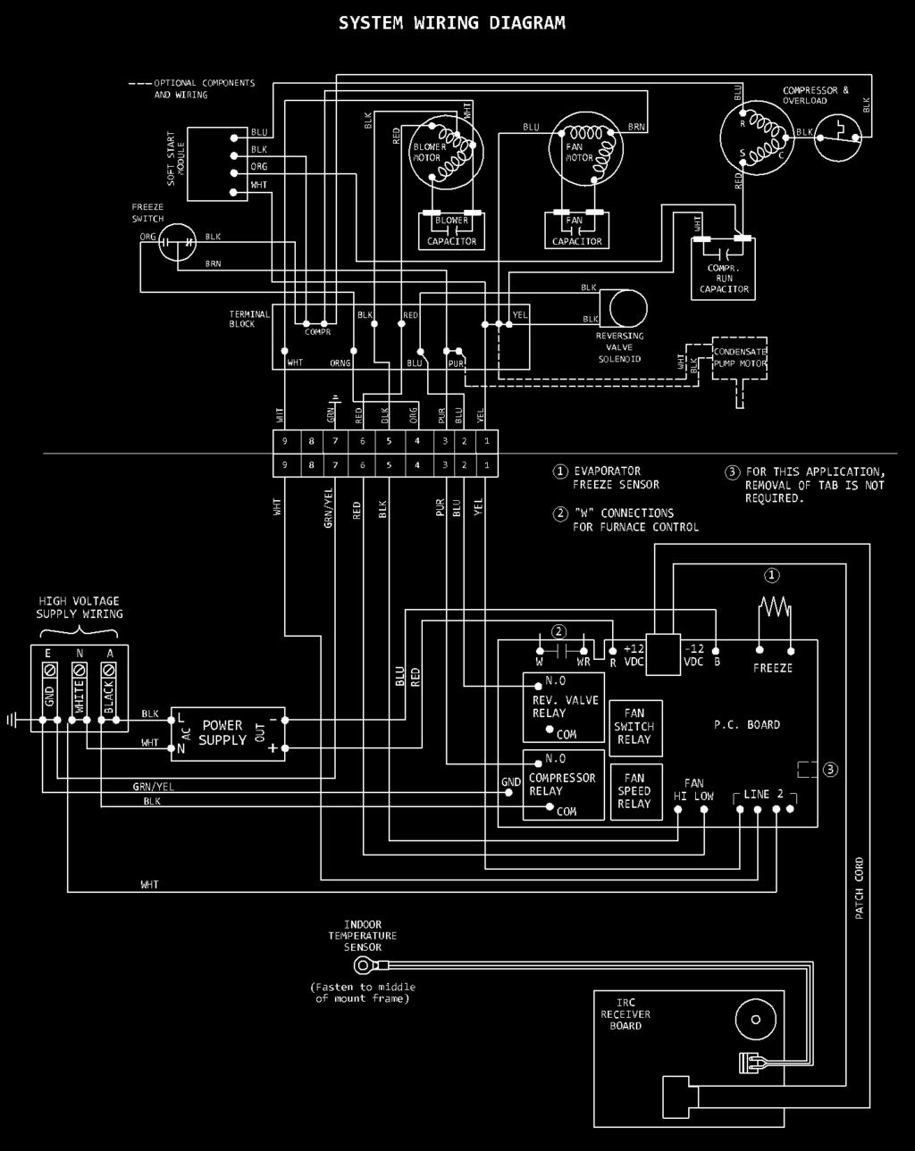
8 VII. 8

9 VIII. INSTALLING THE CEILING ASSEMBLY Refer to Figures 5 and 6 NOTE The following step by step instructions must be performed in sequence to insure a quick and easy installation. A. Remove the grilles and filters from the ceiling assembly shroud. B. Locate the cloth duct assembly and attach to the upper unit basepan with three of the provided short screws. C. Raise the ceiling assembly chute to align with the cloth duct assembly. Attach the chute to the steel mount frame with 4 short screws provided. Unfurl the cloth duct to drop through the ceiling assembly opening. D. Gently peel off the release liner from the VHB (Very High Bond) double sided tape. Press the cloth duct uniformly around the perimeter of the opening to adhere the cloth duct to the plastic chute. Carefully trim the excess cloth duct (a razor knife is very effective for this). E. Plug in the room temperature sensor to the receptacle on the ceiling assembly shroud. Raise the shroud up near the mount frame and push the temperature sensor up through the center opening of the air chute and allow the sensor to hang over the side of the chute. Plug in the patch cord from the upper unit to the receptacle on the ceiling shroud as shown in the magnified section of Figure 6. F. Align the shroud with the air chute insuring that no wires are trapped between plastic parts. Attach the shroud to the steel frame with 4 short screws provided. G. Attach the room temperature sensor to a middle hole of the steel mount frame with a short screw provided. H. Replace the filters and retaining grilles. Using the long screws provided, mount the hand held remote control holster to an interior wall at a height of 24 cm. in a location to prevent outlet air from playing onto the remote control and within line of sight to the ceiling assembly sensor. Avoid locations near heat producing appliances or direct exposure to sunlight. This is particularly important if using the follow me mode of the system in which the temperature sensing will be by the hand held remote instead of the sensor mounted in the ceiling assembly return airstream. I. Install the batteries into the hand held unit. J. Restore power to the system. This concludes the installation of the system. The owner s manual contains the operating and maintenance instructions. FIGURE 5 9

10 FIGURE 6 10

11 RV Products Division Airxcel, Inc. RV Products Division P.O. Box 4020 Wichita, KS (1-14) PP 11
INSTALLATION INSTRUCTIONS FOR. 230/240 VAC, 1ø, 50Hz 473X3 SERIES RV ROOF TOP AIR CONDITIONER
 INSTALLATION INSTRUCTIONS FOR 230/240 VAC, 1ø, 50Hz 473X3 SERIES RV ROOF TOP AIR CONDITIONER Service Contact: Coast to Coast RV Services Pty Ltd. PO BOX 415 REGENTS PARK DC NSW 2143 Australia Tel: +61-2-9645
RV Products Division INSTALLATION INSTRUCTIONS FOR SERIES HEAT PUMP INSTRUCTIONS D INSTALLATION DE LA POMPE À CHALEUR SÉRIE 47000
 RV Products Division INSTALLATION INSTRUCTIONS FOR 47000 SERIES HEAT PUMP INSTRUCTIONS D INSTALLATION DE LA POMPE À CHALEUR SÉRIE 47000 TABLE OF CONTENTS I. General Information..............................................
RV Products Division INSTALLATION INSTRUCTIONS FOR SERIES AIR CONDITIONERS
 RV Products Division INSTALLATION INSTRUCTIONS FOR 47000 SERIES AIR CONDITIONERS These instructions are a general guide for installing the 47000 Series Coleman-Mach 8 roof top air conditioners. For specific
INSTALLATION INSTRUCTIONS FOR 6797A737 HEAT PUMP FLUSH MOUNT CEILING PLENUM
 INSTALLATION INSTRUCTIONS FOR 6797A737 HEAT PUMP FLUSH MOUNT CEILING PLENUM TABLE OF CONTENTS Warnings............................................................................... 2 Package Contents........................................................................
INSTALLATION INSTRUCTIONS FOR 7370A736 FLUSH MOUNT CEILING PLENUM
 INSTALLATION INSTRUCTIONS FOR 7370A736 FLUSH MOUNT CEILING PLENUM TABLE OF CONTENTS Warnings...2 Package Contents...2 General Information...3 Ceiling Plenum Installation Requirement...3 Supply Ducting
INSTALLATION INSTRUCTIONS FOR 8330*633* COOL ONLY A/C 8330*635* HEAT READY A/C 8530*63** HEAT PUMP CHILLGRILLE FLUSH MOUNT CEILING ASSEMBLY
 RV Products Division INSTALLATION INSTRUCTIONS FOR 8330*633* COOL ONLY A/C 8330*635* HEAT READY A/C 8530*63** HEAT PUMP CHILLGRILLE FLUSH MOUNT CEILING ASSEMBLY DESIGNED AND MANUFACTURED BY THE MAKERS
INSTALLATION INSTRUCTIONS FOR 9330F4552 FREE DELIVERY PLENUM KITS
 RV Products Division INSTALLATION INSTRUCTIONS FOR 9330F4552 FREE DELIVERY PLENUM KITS 8330-752 CONTROL BOX KIT (12 VDC COOL ONLY) 9330C755 CONTROL BOX KIT (12 VDC HEAT READY) 8530-750 CONTROL BOX KIT
INSTALLATION INSTRUCTIONS FOR 8330*63**, 8530*63** CHILLGRILLE FLUSH MOUNT CEILING ASSEMBLY
 RV Products Division INSTALLATION INSTRUCTIONS FOR 8330*63**, 8530*63** CHILLGRILLE FLUSH MOUNT CEILING ASSEMBLY DESIGNED AND MANUFACTURED BY THE MAKERS OF COLEMAN -MACH AIR CONDITIONERS TABLE OF CONTENTS
INSTALLATION INSTRUCTIONS FOR 6532 SERIES PACKAGE HEAT PUMP
 INSTALLATION INSTRUCTIONS FOR 6532 SERIES PACKAGE HEAT PUMP RV Products A Division of Airxcel, Inc. P.O. Box 4020 Wichita, KS 67204 1976-360 (1-02) PP TABLE OF CONTENTS 1. Warnings......................................................
INSTALLATION INSTRUCTIONS FOR 6536 SERIES TWO TON PACKAGED HEAT PUMP
 INSTALLATION INSTRUCTIONS FOR 6536 SERIES TWO TON PACKAGED HEAT PUMP TABLE OF CONTENTS 1. Warnings...2 2. Component Match-Up...2 3. Unit Depiction Figures...3 4. Blower Performance Data...5 5. General
INSTALLATION INSTRUCTIONS FOR SERIES TWO TON HIGH EFFICIENCY PACKAGED HEAT PUMP
 RV Products Division INSTALLATION INSTRUCTIONS FOR 46515 SERIES TWO TON HIGH EFFICIENCY PACKAGED HEAT PUMP TABLE OF CONTENTS 1. Warnings.................................................. 2 2. Component
INSTALLATION INSTRUCTIONS FOR 7330C740 FLUSH MOUNT CEILING ASSEMBLY
 INSTALLATION INSTRUCTIONS FOR 7330C740 FLUSH MOUNT CEILING ASSEMBLY TABLE OF CONTENTS Warnings...3 Package Contents...3 General Information...3 Supply Ducting And Registers...3 Routing 115 VAC Wiring...5
INSTALLATION INSTRUCTIONS FOR 8330*5511 MOUNTING KIT
 RV Products Division INSTALLATION INSTRUCTIONS FOR 8330*5511 MOUNTING KIT 8330-752 CONTROL BOX KIT (12 VDC COOL ONLY) 9330A755 CONTROL BOX KIT (12 VDC HEAT/COOL) 8530-750 CONTROL BOX KIT (24 VAC COOL ONLY)
INSTALLATION INSTRUCTIONS FOR 6636 SERIES PACKAGE AIR CONDITIONER
 INSTALLATION INSTRUCTIONS FOR 6636 SERIES PACKAGE AIR CONDITIONER TABLE OF CONTENTS 1. Warnings...................................................... 3 2. Component Match-Up...........................................
INSTALLATION INSTRUCTIONS FOR MOUNTING KIT
 RV Products Division INSTALLATION INSTRUCTIONS FOR 8330-5501 MOUNTING KIT 8330-752 CONTROL BOX KIT (12 VDC COOL ONLY) 9330B755 CONTROL BOX KIT (12 VDC HEAT/COOL) 8530-750 CONTROL BOX KIT (24 VAC COOL ONLY)
RV Products Division INSTALLATION INSTRUCTIONS FOR SERIES PACKAGE AIR CONDITIONER
 RV Products Division INSTALLATION INSTRUCTIONS FOR 46413 SERIES PACKAGE AIR CONDITIONER 1. WARNINGS IMPORTANT NOTICE These instructions are for the use of qualified individuals specially trained and experienced
INSTALLATION INSTRUCTIONS FOR MOUNTING KIT 7330B751 CONTROL BOX KIT (12 VDC COOL ONLY) CONTROL BOX KIT (12 VDC HEAT/COOL)
 CONTROL BOX KIT (12 VDC HEAT/COOL)") INSTALLATION INSTRUCTIONS FOR 8330-5511 MOUNTING KIT 7330B751 CONTROL BOX KIT (12 VDC COOL ONLY) 9330-755 CONTROL BOX KIT (12 VDC HEAT/COOL) 7530B750 CONTROL BOX KIT (24 VAC COOL ONLY) 9530-755 CONTROL
INSTALLATION INSTRUCTIONS FOR 8330-5511 MOUNTING KIT 7330B751 CONTROL BOX KIT (12 VDC COOL ONLY) 9330-755 CONTROL BOX KIT (12 VDC HEAT/COOL) 7530B750 CONTROL BOX KIT (24 VAC COOL ONLY) 9530-755 CONTROL
INSTALLATION INSTRUCTIONS FOR 7330*5511 OR 7330*5512 MOUNTING KIT 7330B751 CONTROL BOX KIT (12 VDC COOL ONLY)
") INSTALLATION INSTRUCTIONS FOR 7330*5511 OR 7330*5512 MOUNTING KIT 7330B751 CONTROL BOX KIT (12 VDC COOL ONLY) 7530B750 CONTROL BOX KIT (24 VAC COOL ONLY) 8330A751 ZONE CONTROL KIT (12 VDC COOL ONLY) 8530B751
INSTALLATION INSTRUCTIONS FOR 7330*5511 OR 7330*5512 MOUNTING KIT 7330B751 CONTROL BOX KIT (12 VDC COOL ONLY) 7530B750 CONTROL BOX KIT (24 VAC COOL ONLY) 8330A751 ZONE CONTROL KIT (12 VDC COOL ONLY) 8530B751
SERVICE MANUAL FOR 6633 SERIES PACKAGE AIR CONDITIONER
 SERVICE MANUAL FOR 6633 SERIES PACKAGE AIR CONDITIONER TABLE OF CONTENTS 1. Warnings...................................................... 3 2. Component Match-Up...........................................
SERVICE MANUAL FOR 6636A & 6636B SERIES TWO TON HIGH EFFICIENCY PACKAGED AIR CONDITIONERS
 SERVICE MANUAL FOR 6636A & 6636B SERIES TWO TON HIGH EFFICIENCY PACKAGED AIR CONDITIONERS TABLE OF CONTENTS 1. Warnings & Component Match-Up............................................ 2 2. Unit Specifications..........................................................
OPERATION AND MAINTENANCE INSTRUCTIONS FOR ROOF TOP HEAT PUMPS AND CEILING PLENUMS
 OPERATION AND MAINTENANCE INSTRUCTIONS FOR ROOF TOP HEAT PUMPS AND CEILING PLENUMS RV Products A Division of Airxcel, Inc. P.O. Box 4020 Wichita, KS 67204 1976H207 (10-06) PP TABLE OF CONTENTS I. General
OPERATION AND MAINTENANCE INSTRUCTIONS FOR ROOF TOP HEAT PUMPS AND CEILING PLENUMS
 OPERATION AND MAINTENANCE INSTRUCTIONS FOR ROOF TOP HEAT PUMPS AND CEILING PLENUMS TABLE OF CONTENTS I. General Information.................................................. 2 II. Standard Ceiling Plenum
LIFTAIRE II ELEVATOR AIR CONDITIONER
 LIFTAIRE II ELEVATOR AIR CONDITIONER THE LATEST IN A SERIES OF AIR CONDITIONERS/HEATERS DESIGNED SPECIFICALLY FOR USE IN ELEVATORS. Airxcel, the maker of the #1 brand of air conditioners in the recreational
LIFTAIRE I ELEVATOR AIR CONDITIONER
 LIFTAIRE I ELEVATOR AIR CONDITIONER THE AIR CONDITIONER/HEATER DESIGNED SPECIFICALLY FOR ELEVATORS. Now Airxcel, the best selling brand in the recreation vehicle industry, has incorporated its unique experience
INSTALLATION & OPERATING INSTRUCTIONS. Roof Top Unit. Model. USA SERVICE OFFICE Dometic Corporation 2320 Industrial Parkway Elkhart, IN 46516
 RECORD THIS INFORMATION FOR FUTURE REFERENCE: Model Number Serial Number ADB Model Number ADB Serial Number Date Purchased USA SERVICE OFFICE Dometic Corporation 2320 Industrial Parkway Elkhart, IN 46516
CONTENTS A FEW WORDS ABOUT YOUR NEW AIR CONDITIONING UNIT 2 ELECTRICAL DATA 2 OPERATING INSTRUCTIONS 4
 CONTENTS A FEW WORDS ABOUT YOUR NEW AIR CONDITIONING UNIT 2 ELECTRICAL DATA 2 OPERATING INSTRUCTIONS 4 CEILING UNIT DISPLAY 4 REMOTE CONTROL DESCRIPTIONS 5 COMPRESSOR DELAY FUNCTION 7 REMOTE CONTROL PREPARATION
BR342 Ducted Installation Instructions Australian Version Electronic Wall Control
 Australian Version Electronic Wall Control 1 Introduction The BR342 reverse cycle rooftop air-conditioner is designed for installation onto Recreational Vehicles (RV s) at the time of manufacture or as
OPERATION AND MAINTENANCE INSTRUCTIONS FOR SERIES ROOF TOP HEAT PUMPS AND CEILING PLENUMS
 RV Products Division OPERATION AND MAINTENANCE INSTRUCTIONS FOR 47000 SERIES ROOF TOP HEAT PUMPS AND CEILING PLENUMS CONSIGNES D ENTRETIEN ET D EXPLOITATION POUR LES THERMOPOMPES DE TOIT ET LES CHAMBRES
SERVICE MANUAL FOR 6795B,C,D SERIES PACKAGED AIR CONDITIONERS
 SERVICE MANUAL FOR 6795B,C,D SERIES PACKAGED AIR CONDITIONERS TABLE OF CONTENTS 1. Warnings.................................................................. 2 2. Unit Dimensions And Specifications............................................
INSTALLATION INSTRUCTIONS FOR MODEL 7330D3351 & 7330D3361 WALL THERMOSTAT
 INSTALLATION INSTRUCTIONS FOR MODEL 7330D3351 & 7330D3361 WALL THERMOSTAT APPLICATION These thermostats are designed to operate all R.V. Products ceiling assemblies, which control the air conditioner 115
SERVICE MANUAL FOR ROOF TOP AIR CONDITIONERS
 SERVICE MANUAL FOR ROOF TOP AIR CONDITIONERS PREFACE This service manual is primarily intended for the use of qualified individuals specially trained and experienced in the service of this type of equipment
Roof Top Unit. Description Model Type Use With Air Distribution Box Model B CX51R B CX51R
 RECORD THIS UNIT INFORMATION FOR FUTURE REFERENCE: Type Number Product Number Serial Number ADB Number ADB Serial Number Date Purchased Roof Top Unit Description Model Type Use With Air Distribution Box
Installation Instructions. For the 18 Built-In Dishwasher and Front Color Panels
 Installation Instructions For the 18 Built-In Dishwasher and Front Color Panels Printed in USA 154232102 Before You Begin DO NOT INSTALL DISHWASHER UNTIL YOU HAVE READ ALL INSTRUCTIONS. FOR YOUR SAFETY,
OPERATION AND MAINTENANCE INSTRUCTIONS FOR 6535 AND 6536 SERIES TWO TON PACKAGED HEAT PUMP
 RV Products Division OPERATION AND MAINTENANCE INSTRUCTIONS FOR 6535 AND 6536 SERIES TWO TON PACKAGED HEAT PUMP TABLE OF CONTENTS I. Specifications....................................... 2 II. General
BUILT-IN DISHWASHER INSTALLATION INSTRUCTIONS
 BUILT-IN DISHWASHER INSTALLATION INSTRUCTIONS PLEASE READ COMPLETE INSTRUCTIONS BEFORE YOU BEGIN LEAVE INSTALLATION INSTRUCTIONS AND USER'S GUIDE WITH OWNER ALL ELECTRIC WIRING AND PLUMBING MUST BE DONE
SERVICE MANUAL FOR 6537 & 6538 SERIES TWO TON HIGH EFFICIENCY PACKAGED HEAT PUMPS
 SERVICE MANUAL FOR 6537 & 6538 SERIES TWO TON HIGH EFFICIENCY PACKAGED HEAT PUMPS TABLE OF CONTENTS 1. Warnings.................................................................. 2 2. Accessibility Of Appliance....................................................
installation and start-up instructions HUMIDIFIERS AND HUMIDISTAT
 installation and start-up instructions HUMIDIFIERS AND HUMIDISTAT HUM Cancels: II 912D-56-3 II HUM-56-1 7-98 MODEL HUMBBLFP1025-A-- FAN-POWERED HUMIDIFIER MODEL HUMBBLBP2018-A-- BYPASS HUMIDIFIER MODEL
INSTALLATION INSTRUCTIONS UNDERCOUNTER DISHWASHERS
 INSTALLATION INSTRUCTIONS UNDERCOUNTER DISHWASHERS VIKING 111 Front Street Greenwood, Mississippi 38930 USA (662) 455-1200 IMPORTANT - PLEASE READ AND FOLLOW Before beginning - please read these instructions
Air Conditioner
 RECORD THIS UNIT INFORMATION FOR FUTURE REFERENCE: Model Number Serial Number Date Purchased USA SERVICE OFFICE Dometic, LLC 2320 Industrial Parkway Elkhart, IN 46516 574-294-2511 Roof Top Unit Description
OPERATION & MAINTENANCE INSTRUCTIONS FOR. 230/240 VAC, 1ø, 50Hz
 RV Products Division OPERATION & MAINTENANCE INSTRUCTIONS FOR 230/240 VAC, 1ø, 50Hz 47000 SERIES RV ROOF TOP AIR CONDITIONER/HEAT PUMP AND REMOTE CONTROLLER Service Contact: Coast to Coast RV Services
Installation Guide. 15 W. Undercounter/Freestanding Nugget Ice Machine U L. Viking Range, LLC. 111 Front Street
 Installation Guide Viking Range, LLC 111 Front Street Greenwood, Mississippi 38930 USA (662) 455-1200 For product information, call 1-888-(845-4641) or visit our web site at vikingrange.com in the US or
Viking Installation Guide
 Viking Installation Guide Viking Range Corporation 111 Front Street Greenwood, Mississippi 38930 USA (662) 455-1200 For product information, call 1-888-VIKING1 (845-4641) or visit the Viking Web site at
13500 BTU RV Air Conditioner Installation and Operating Instructions
 13500 BTU RV Air Conditioner Installation and Operating Instructions Model No.:HCB-R135-A-ID HCB-R135-A-OD 3092402 V140804 Thank you for choosing a Soleus Air RV Air Conditioner. This owner s manual will
Installation Instructions
 Installation Instructions Before you begin... 2 Location... 2 Recommended grounding instructions... 2 Electrical requirements... 2 Exhaust requirements... 3 Water supply and drain requirements... 3 Please
GE Monogram. Installation. Instructions. Stainless Steel Bottom Mount Built-In Refrigerators. Models ZICS36N RH ZICS36N LH
 GE Monogram Installation Instructions Stainless Steel Bottom Mount Built-In Refrigerators Models ZICS36N RH ZICS36N LH Before you begin - Read these instructions completely and carefully. IMPORTANT - Save
Installation Instructions
 Installation Instructions For the 18" Built-In Dishwasher Sears, Roebuck and Co. Sears Canada, Inc. Hoffman Estates, IL 60179 U.S.A. Toronto, Ontario, Canada M5B 2B8 154435201 Before You Begin DO NOT INSTALL
INSTALLATION INSTRUCTIONS ELECTRIC DRYER
 INSTALLATION INSTRUCTIONS ELECTRIC DRYER Table of Contents... 2 IMPORTANT: Save for local electrical inspector s use. 3397627C DRYER SAFETY... 2 INSTALLATION INSTRUCTIONS... 4 Tools and Parts... 4 Location
INSTALLATION INSTRUCTIONS
 INSTALLATION INSTRUCTIONS BUILT-IN BOTTOM MOUNT REFRIGERATOR/FREEZER BRTGK72SS-GRILLE KIT (FOR PROFESSIONAL SERIES ONLY) VIKING RANGE CORPORATION 111 Front Street Greenwood, Mississippi (MS) 38930 USA
Installation Instructions
 Installation Instructions Built-In Dishwasher If you have questions, call 800-944-9400(US),800-245-8352(Canada)or visit our website at: www.frigidaire.com BEFORE YOU BEGIN Read these instructions completely
INSTALLATION INSTRUCTIONS
 INSTALLATION INSTRUCTIONS BUILT-IN BOTTOM MOUNT REFRIGERATOR/FREEZER DBRTGK72SS-GRILLE KIT (FOR designer SERIES ONLY) VIKING RANGE CORPORATION 111 Front Street Greenwood, Mississippi (MS) 38930 USA (662)
Installation Instructions
 Installation Instructions Built-In Dishwasher If you have questions, call 800-GECARES or visit our website at: www.geappliances.com BEFORE YOU BEGIN Read these instructions completely and carefully. IMPORTANT
Installation instructions for vented tumble dryer DOMESTIC. Dear Customer,
 Dear Customer, Read these instructions carefully and completely before you install the machine. The installation should be carried out by a qualified person who is familiar with all local codes and ordinances
INSTALLATION INSTRUCTIONS
 INSTALLATION INSTRUCTIONS - Wall-mount indoor unit - OPERATING LIMITS Cooling Maximum conditions Heating Maximum conditions Outdoor temperature : 122 F (50 C) D.B. Outdoor temperature : 75 F (24 C) D.B.
MODEL Roof-Top Heat Pump used with Air Distribution Box Kit
 R RECORD THIS INFORMATION FOR FUTURE REFERENCE BEFORE INSTALLING THE UNIT: Model Number Serial Number Date Purchased Place of Purchase USA SERVICE OFFICE The Dometic Corp. 509 So. Poplar St. LaGrange,
Installation. 324 Series Built-In Dishwashers U L. Viking Range, LLC 111 Front Street Greenwood, Mississippi USA (662)
") Installation Viking Range, LLC Front Street Greenwood, Mississippi 890 USA (66) 455-00 For product information, call -888-845-464 or visit the Viking Website at vikingrange.com U L C U L 4 Series Built-In
Installation Viking Range, LLC Front Street Greenwood, Mississippi 890 USA (66) 455-00 For product information, call -888-845-464 or visit the Viking Website at vikingrange.com U L C U L 4 Series Built-In
UB1 AIR CONDITIONING UNIT INSTALLATION INSTRUCTIONS
 UB1 AIR CONDITIONING UNIT INSTALLATION INSTRUCTIONS INSTALLATION INSTRUCTIONS: Carefully read these instructions before installing your new air-conditioner. AUSTRALIAN AUTOMOTIVE AIR AL00500054E 1 Table
29 IN. (73.7 CM) ELECTRIC DRYER INSTALLATION INSTRUCTIONS DRYER SAFETY
 ELECTRIC DRYER INSTALLATION INSTRUCTIONS DRYER SAFETY") 9 IN. (7.7 CM) ELECTRIC DRYER INSTALLATION INSTRUCTIONS DRYER SAFETY... INSTALLATION INSTRUCTIONS... Tools and Parts... Location Requirements... Electrical Requirements... Electrical Connection...4 Venting
9 IN. (7.7 CM) ELECTRIC DRYER INSTALLATION INSTRUCTIONS DRYER SAFETY... INSTALLATION INSTRUCTIONS... Tools and Parts... Location Requirements... Electrical Requirements... Electrical Connection...4 Venting
OPERATION AND MAINTENANCE INSTRUCTIONS FOR SERIES TWO TON PACKAGED HEAT PUMP
 OPERATION AND MAINTENANCE INSTRUCTIONS FOR 46516 SERIES TWO TON PACKAGED HEAT PUMP Airxcel, Inc. P.O. Box 4020 Wichita, KS 67204 1976-554 (2-10) PP TABLE OF CONTENTS I. Specifications.........................................
Installation Instructions
 Installation Instructions For Fully Integrated NoFrost Combined Refrigerator-Freezers HC 2060/2061 7082 485-00 Important PLEASE READ AND FOLLOW THESE INSTRUCTIONS These instructions contain Warning and
Installation. 15 W. Undercounter/Freestanding Ice Machine FGIM515 / CFGIM515 FPIM515 / CFPIM515
 Installation 15 W. Undercounter/Freestanding Ice Machine FGIM515 / CFGIM515 FPIM515 / CFPIM515 TABLE OF CONTENTS Warnings & Important Safety Instructions 3 Dimensions (Professional) 5 Dimensions (Custom
IMPORTANT INFORMATION. Revised Dishwasher Installation Instructions
 IMPORTANT INFORMATION Revised Dishwasher Installation Instructions To obtain a revised copy of the entire Dishwasher User s Manual, go to www.eurotechappliances.com. SPECIAL EDITION 11-20-02 SAVE THESE
Installation Instructions
 Dear customer! Thank you for choosing this quality product from ASKO. We hope it will meet your expectations and fulfil your needs for many years to come. Scandinavian design combines clean lines, everyday
DISHWASHER INSTALLATION GUIDE SPECIFICATIONS, INSTALLATION, AND MORE
 DISHWASHER INSTALLATION GUIDE SPECIFICATIONS, INSTALLATION, AND MORE COVE DISHWASHER Contents 3 Cove Dishwasher 4 Specifications 7 Door Panel 9 Installation 15 Troubleshooting Features and specifications
THE QUALITY BRAND IN FANS
 THE QUALITY BRAND IN FANS Minor design changes or otherwise may result in slight variations between the product illustrated and that which is contained within this package INSTALLATION AND OPERATION INSTRUCTION
Summer Breeze Heater Service Manual
 Summer Breeze Heater Service Manual RSBH RSBH-SB RSBHP Revision: 1.0 Issued: 12-18-2012 Table of Contents I. Basic Assembly and Operation A. Safety Instructions... 2 B. Grounding Instructions... 3 C.
Installation Instructions Built-In Dishwasher
 GE Consumer & Industrial Appliances Installation Instructions Built-In Dishwasher If you have questions, call 800.GE.CARES (800.432.2737) or visit our website at: www.ge.com BEFORE YOU BEGIN Read these
INSTALLATION INSTRUCTIONS
 INSTALLATION INSTRUCTIONS PACKAGED HEAT PUMP Table of Contents GENERAL INFORMATION.................. 2 VISUALLY INSPECT PRODUCT............... 2 INTRODUCTION........................... 2 OPTIONAL KITS...........................
INSTALLATION INSTRUCTIONS TD75. Vented tumble dryer DOMESTIC. Carefully read the instructions for use before using the dryer.
 INSTALLATION INSTRUCTIONS TD75 Vented tumble dryer DOMESTIC Carefully read the instructions for use before using the dryer. Dear Customer, Read these instructions carefully and completely before you install
USER S MANUAL AND INSTALLATION INSTRUCTIONS IMPORTANT
 USER S MANUAL AND INSTALLATION INSTRUCTIONS P3BD Series 13 SEER Single Package Air Conditioner IMPORTANT Read this owner information to become familiar with the capabilities and use of your appliance.
DIRECT DRAW BEER COOLERS Installation, Operation and Maintenance Instructions
 DIRECT DRAW BEER COOLERS Installation, Operation and Maintenance Instructions INSPECTION When the equipment is received, all items should be carefully checked against the Bill of Lading to ensure all crates
DISHWASHER. Models DW2432 and DW2432SS. Installation Manual. Write Serial Number (on inner door of unit) here:
 here:") DISHWASHER Models DW2432 and DW2432SS Installation Manual Write Serial Number (on inner door of unit) here: Felix Storch, Inc. Summit Appliance Division 770 Garrison Avenue Bronx, New York 10474 www.summitappliance.com
DISHWASHER Models DW2432 and DW2432SS Installation Manual Write Serial Number (on inner door of unit) here: Felix Storch, Inc. Summit Appliance Division 770 Garrison Avenue Bronx, New York 10474 www.summitappliance.com
Installation Instructions
 GE Consumer & Industrial Appliances Installation Instructions Junction Box Cover Within this user bag, you will find a junction box cover and a #10 hex head screw used to attach the junction box cover
09/23/2013. RECORD THIS UNIT INFORMATION FOR FUTURE REFERENCE: Model Number: Serial Number: Date Purchased:
 AIR CDITIER & HEAT PUMP DIGITAL CTROL FOR DUCTED SYSTEM INSTALLATI AND OPERATING INSTRUCTIS FOR ACM135, ACM135SP,ACM150,ACM150SP,ACRG15,ACTH12 RECORD THIS UNIT INFORMATI FOR FUTURE REFERENCE: Model Number:
Installation Instructions
 Installation Instructions For Fully Integrated NoFrost Combined Refrigerator-Freezers HC 2062 HCB 2062 HC/HCB 20 7082 373-00 Important PLEASE READ AND FOLLOW THESE INSTRUCTIONS These instructions contain
SLIDER CASEMENT AIR CONDITIONER
 OWNER S GUIDE READ AND SAVE THESE INSTRUCTIONS SLIDER CASEMENT AIR CONDITIONER ROTARY CONTROL P/N 309000854 (11/03) ROOM AIR CONDITIONER WARRANTY Your product is protected by this warranty Your appliance
BlueHeat AirTop 2000 Heater
 BlueHeat AirTop 000 Heater Air Heater Installation Manual Ford E-Series 6.0L Diesel Beginning Model Year: 006 Special instructions for these models Part locations may differ slightly dependent on the vehicle
Built-In Dishwasher. Installation Instructions. BEFORE YOU BEGIN Read these instructions completely and carefully. IMPORTANT The dishwasher MUST be
 Installation Instructions Built-In Dishwasher If you have questions, call 800.GE.CARES (800.432.2737) or visit our website at: www.ge.com BEFORE YOU BEGIN Read these instructions completely and carefully.
Installation Instructions
 GE Consumer & Industrial Appliances Installation Instructions Junction Box Cover Within this user bag, you will find a junction box cover and a #10 hex head screw used to attach the junction box cover
Service Parts for models UF424 and UN324
 Service Parts for models UF and UN This is the illustrated parts list for Scotsman ice maker models UF and UF. They were manufactured as either air or water cooled models, plus the air cooled models were
Top Control Dishwasher
 INSTALLATION GUIDE Top Control Dishwasher NS-DWH2BS8/NS-DWH2SS8/NS-DWR2BS8/NS-DWR2WH8/NS-DWR2SS8 Before using your new product, please read these instructions to prevent any damage. Contents Introduction......................................................................................................
Dishwasher Installation Instructions DW 24XT/DW 24XV
 Dishwasher Installation Instructions DW 24XT/DW 24XV Installation Instructions Dishwasher BEFORE YOU BEGIN Read these instructions completely and carefully. IMPORTANT Observe all governing codes and ordinances.
AIR CONDITIONER ELECTRONIC CONTROL
 READ AND SAVE THESE INSTRUCTIONS AIR CONDITIONER ELECTRONIC CONTROL ROOM AIR CONDITIONER WARRANTY Your product is protected by this warranty Your appliance is warranted by Electrolux. Electrolux has authorized
Installation Instructions 30 French Door Built-in Wall Ovens
 Installation Instructions 30 French Door Built-in Wall Ovens Questions? Call 1.800.GE.CARES (1.800.432.2737) or visit www.geappliances.com In Canada, call 1.800.561.3344 or visit www.geappliances.ca DESIGN
DISHWASHER INSTALLATION INSTRUCTIONS
 DISHWASHER INSTALLATION INSTRUCTIONS IMPORTANT! Read all of these instructions before installing the dishwasher. AUTOMATIC HIGH LOOP The drain hose is fastened to the back of the machine at the best height.
BRISK AIR 579 Series 590 Series 595 Series
 RECORD THIS UNIT INFORMATION FOR FUTURE REFERENCE: Model Number Serial Number Date Purchased USA SERVICE OFFICE The Dometic Corporation 220 Industrial Parkway Elkhart, IN 6515 (57) 29-2511 CANADA Dometic
 Installation Guide BI-98 Ice Maker www.u-lineservice.com Phone (414) 354-0300 FAX (414) 354-7905 Service & Parts Tech Lines Phone (800) 779-2547 FAX (414) 354-5696 OnlineService@U-Line.com 2005 U-Line
Flat Wall Mounted / Free stand Electric Fireplace. Model Numbers: S OWNER S MANUAL. Wall Hanging Mode. Freestanding Mode AC 120V / 60HZ 1500W
 Flat Wall Mounted / Free stand Electric Fireplace Model Numbers: 80-421S OWNER S MANUAL Wall Hanging Mode Freestanding Mode AC 120V / 60HZ 1500W WARNING Read and understand this entire owner s manual,
TECHNICIAN'S MANUAL 1989 REFRIGERATORS MODELS BCS42CKB/C BCS42EK BCS42EL BIS42CKB/C BISB42EK BISW42EK BISB42EL BISW42EL HOTPOINT
 GENERAL ELECTRIC REFRIGERATORS AND FREEZERS HOTPOINT TECHNICIAN'S MANUAL BIS42CKB/C BISB42EK BISW42EK BISB42EL BISW42EL MODELS BCS42CKB/C BCS42EK BCS42EL General Electric Co. 1989 Pub. No. 31-5214 GENERAL
INSTALLATION. Glass Panel Doors (select models) CAUTION
 CAUTION") Location Do not install refrigerator near oven, radiator or other heat source. If not possible, shield refrigerator with cabinet material. Do not install where temperature falls below 55 F (13 C) or rises
Location Do not install refrigerator near oven, radiator or other heat source. If not possible, shield refrigerator with cabinet material. Do not install where temperature falls below 55 F (13 C) or rises
Questions? Call 800.GE.CARES ( ) or visit our Web site at: GEAppliances.com In Canada, call or visit
 or visit our Web site at: GEAppliances.com In Canada, call or visit") Installation Instructions Electric Dryer 01 Questions? Call 800.GE.CARES (800.432.2737) or visit our Web site at: GEAppliances.com In Canada, call 1.800.561.3344 or visit www.geappliances.ca BEFORE YOU
Installation Instructions Electric Dryer 01 Questions? Call 800.GE.CARES (800.432.2737) or visit our Web site at: GEAppliances.com In Canada, call 1.800.561.3344 or visit www.geappliances.ca BEFORE YOU
72 ONYX XL FLAT PANEL ELECTRIC FIREPLACE
 72 ONYX XL FLAT PANEL ELECTRIC FIREPLACE Model Numbers: 80005 OWNER S MANUAL WARNING Read and understand this entire owner s manual, including all safety information, before plugging in or using this product.
F6102 Installation & Operating Instructions for the Parrotuncle Owner s Installation,Manual WARNING: SHUT POWER OFF AT FUSE OR CIRCUIT BREAKER
 CAUTION READ INSTRUCTIONS CAREFULLY FOR SAFE INSTALLATION AND FAN OPERATION. IF UNSURE CONSULT A QUALIFIED ELECTRICIAN F6102 THANK YOU FOR YOUR PURCHASE Thank you for purchasing this quality product. To
Installation. Built-in Full Height Wine Cellar VCWB301
 Installation Built-in Full Height Wine Cellar VCWB301 Table of Contents Warnings & Important Information _ 3 Dimensions _ 5 Specifications _ 6 Cutout Dimensions 7 Cabinet Information _ 8 Cabinet Information
RVAC-100 VACUUM CLEANER MANUAL. For Household Use Only
 VACUUM CLEANER MANUAL RVAC-100 For Household Use Only 790 Rowntree Dairy Road, Woodbridge, ON Canada L4L 5V3 t: 905.851.6701 f: 905-851.8376 e: info@reversomatic.com Toll Free: 1.800.810.3473 (Canada)
Installation Instructions Built-In Dishwasher
 RINSE CHINA CRYSTAL SPEED CYCLE NORMAL WASH COOK WARE SELECTIONS ANTI BACTERIA START RESET ENHANCEMENTS DELAY HOURS ADDED HEAT PRE WASH HEATED DRY TO LOCK CONTROLS PRESS HEATED DRY FOR 3 SECONDS GE Consumer
A PROUD HERITAGE OF EXPERIENCE & QUALITY DISHWASHER BR-DWSH01-S
 A PROUD HERITAGE OF EXPERIENCE & QUALITY DISHWASHER BR-DWSH01-S, 1 6 7 $ / / $ 7, 2 1, 1 6 7 5 8 & 7, 2 1 6 W W W. V I N O T E M P. C O M Installation Instructions Dishwasher BEFORE YOU BEGIN Read these
DRYER INSTALLATION INSTRUCTIONS
 DRYER INSTALLATION INSTRUCTIONS Table of Contents DRYER SAFETY... 1 INSTALLATION REQUIREMENTS... 2 Tools and Parts... 2 Location Requirements... 3 Electrical Requirements... 5 INSTALLATION INSTRUCTIONS...
Dishwasher. Installation manual DW60M9990AP
 Dishwasher manual DW60M9990AP DW9000M_DD68-00197B-00_EN.indd 1 6/1/2017 4:34:14 PM Contents Contents 3 What s included 3 requirements 7 Dimensions and specifications 9 Step-by-step installation 11 2 English
WKS 2200 SERIES (USA only) --INSTALLATION INSTRUCTIONS--
 --INSTALLATION INSTRUCTIONS--") 8610 Production Avenue San Diego, California 92121 (858) 566-7465 Fax (858) 566-1943 WWW.BREEZAIRE.COM WKS 2200 SERIES (USA only) --INSTALLATION INSTRUCTIONS-- Thank you for choosing a BREEZAIRE cooling
8610 Production Avenue San Diego, California 92121 (858) 566-7465 Fax (858) 566-1943 WWW.BREEZAIRE.COM WKS 2200 SERIES (USA only) --INSTALLATION INSTRUCTIONS-- Thank you for choosing a BREEZAIRE cooling
INSTALLATION MANUAL AND USER GUIDE
 LIFT BRIDGE KITCHEN & BATH MODELS: DSQR110BN and DSQR110ORB INSTALLATION MANUAL AND USER GUIDE Bathroom Ventilation Fan with Light READ AND SAVE THESE INSTRUCTIONS This residential series bathroom fan