INLINE СENTRIFUGAL FAN BOX BOX-R OPERATION MANUAL
|
|
|
- Colin Fleming
- 5 years ago
- Views:
Transcription


1 INLINE СENTRIFUGAL FAN BOX BOX-R OPERATION MANUAL
2 CONTENT 3 Introduction 3 General 3 Safety rules 3 Storage and transportation rules 3 Manufacturer s warranty 4 Fan design 4 Delivery set 5 Technical data 7 Mounting and operation guidelines 9 Connection to power mains 0 Maintenance 0 Fault handling Acceptance certificate Electrical connection certificate Warranty card 2
3 BLAUBERG Company is happy to offer your attention a new high-quality inline centrifugal Blauberg fans. INTRODUCTION The present service instruction contains technical description, technical data sheets, operation and mounting guidelines, safety precautions and warnings for safe and correct operation of the fan. GENERAL The inline centrifugal fans are designed for supply and exhaust ventilation of small domestic, public and production facilities with limited mounting space. The fans are compatible with round Ø 00, 25, 50 and 60 mm air ducts and are designed for ceiling or wall mounting. The fan is rated for continuous operation always connected to power mains. Transported medium must not contain any flammable or explosive mixtures, chemical vapours, coarse dust, soot, fat particles or pathogen favourable environment, poisonous, sticky and fibrous substances. The fans are allowed for operation only after final mounting, that includes installation of protecting devices in compliance with DIN EN ISO 3875 (DIN EN ISO 200) as well as other construction safety equipment. The fan design is regularly improved, so some models can slightly differ from those ones described in this service instruction. SAFETY RULES The fan complies with the requirements according to the EU norms and directives, to the relevant EU-Low Voltage Equipment Directives, EU- Directives on Electromagnetic Compatibility. All operations related to the fan electrical connections, servicing and repair works are allowed only after the fan disconnection from power mains. All mounting and servicing operations are allowed for duly qualified electricians with valid electrical work permit for electric operations at the units up to 000 V after careful study of the present user's manual. The fan must be grounded! Please follow the safety regulations and working instructions (DIN EN 50 0, IEC 364). Make sure the impeller and the casing are not damaged before connecting the fan to power mains. The casing internals must be free of any foreign objects which can damage the impeller blades. Disconnect the fan from power mains prior to any operations related to the fan servicing and repair works. Take measures to prevent contact with the fan to avoid physical damages during the fan step and start-up. Misuse of the product or any unauthorized modification are not allowed. The fan is designed for connection to AC single-phase power mains, see "Technical Data". The fan is rated for permanent operation during non-stop power supply. Take steps to prevent ingress of smoke, carbon monoxide and other combustion products into the room through open chimney flues or other fire-protection devices. Sufficient air supply must be provided for proper combustion and exhaust of gases through the chimney of fuel burning equipment to prevent back drafting. The maximum permitted pressure difference per living units is 4 Pa. The air must not contain any dust or other solid impurities, sticky substances or fibrous materials. The fan is not designed for use in an inflammable and explosive medium. The transported medium must not have an aggressive effect on steel at the temperature stated in the table of the section Technical data. Do not close or block the fan intake or exhaust vent not to disturb the normal air passage. Do not sit on the fan and do not put objects on the fan. Follow the manual guidelines to ensure trouble-free operation and long service life of the product. Hazardous parts access and water ingress protection standard IPX4. STORAGE AND TRANSPORTATION RULES Store the delivered product in the manufacturer's original packing box in a dry ventilated premise with the ambient temperature from +5 C up to + 40 C. Store the fan in an environment with minimized risk of mechanical damages, temperature and humidity fluctuations. Store the fan inside a room or under a shelter. Transport of the product is allowed by any vehicle in the manufacturer's original packing box. Use hoist machinery for handling and transportation to prevent possible mechanical damages of the product. Fulfil the requirements for transportation of the specified cargo type during cargo-handling operations. Do not expose the product to extremely low or high temperatures. MANUFACTURER'S WARRANTY The fan complies with the requirements according to the EU norms and directives, to the relevant EU-Low Voltage Equipment Directives, EU- Directives on Electromagnetic Compatibility. We hereby declare that the following product complies with the essential protection requirements of Electromagnetic Council Directive 2004/08/ EC, 89/336/EEC and Low Voltage Directive 2006/95/EC, 73/23/EEC and CE-marking Directive 93/68/EEC on the approximation of the laws of the Member States relating to electromagnetic compatibility. This certificate is issued following test carried out on samples of the product referred to above. Assessment of compliance of the product with the requirements relating to electromagnetic compatibility was based on the following standards. The manufacturer hereby warrants normal operation of the fan over the period of 2 years from the retail sale date provided observance of the installation and operation regulations. In case of failure due to faulty equipment during the warranty period the consumer has the right to exchange it. If case of no confirmation of the sale date, the warranty term shall be calculated from the manufacturing date. The replacement is offered by the Seller. The MANUFACTURER shall not be liable for any damage resulting from any misuse of or gross mechanic interference with the fan. Please follow the operation guidelines always.! ATTENTION The product is not allowed for use by children and persons with reduced physical, mental or sensory capacities, without proper practical experience or expertise, unless they are controlled or instructed on the product operation by the person(s) responsible for their safety. Supervise the children and do not let them play with the product. WARNING Do not dispose in domestic waste. The unit contains in part material that can be recycled and in part substances that should not end up as domestic waste. Dispose of the unit once it has reached the end of its working life according to the regulations valid where you are. 3
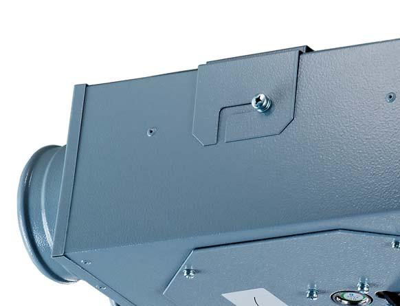
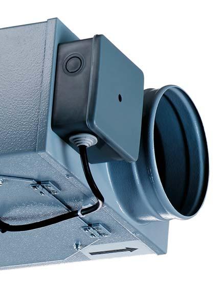
4 FAN DESIGN a) b) Box-R 80/80x2 Box 25/00x2 Box-R 80 Box-R 00 Inlet spigot Box 00 Box 25 Box-50 Box-60 Box-R 00/80x2 Box-R 00/00x2 Inlet spigots Box 50/25x2 Fixing bracket Outlet spigot Cover with impeller Outlet spigot Casing Terminal box inlet - outlet 2 inlets - outlet c) Box-R 80/80x4 Box 25/00x4 d) Box-R 80/80x5 e) Box-R 80/80x6 Box-R 00/80x4 Box-R 00/80x5 Box-R 00/80x6 Box-R 00/00x4 Box-R 00/00x5 Box-R 00/00x6 Inlet spigots Inlet spigots Inlet spigots Outlet spigot 4 inlets - outlet Fig.. Fan modifications Outlet spigot 5 inlets - outlet 6 inlets - outlet The Box-R fan (fig. ) consists of the metal casing with the impeller fixed on the casing cover. The impeller with forward curved blades is located inside of the scroll casing that ends up with an outlet spigot. The terminal box with an operating and an input capacitor and a terminal block inside is attached to the casing end face. The cover with the impeller and a fixing bracket with mounting slots is screwed to the back or front wall of the casing, depending on the fan model. Box-R series are the three-speed fans. The Box fan (fig. ) consists of the metal casing with the impeller with backward curved blades fixed to the casing cover. The terminal box with an operating and an input capacitor and a terminal block inside is attached to the casing end face. The cover with the impeller and a fixing bracket with mounting slots is screwed to the back or front wall of the casing depending on the fan model. Box series are the single-speed fans. DELIVERY SET fan - item; screws and dowels - 4 items; operation manual. 4
5 TECHNICAL DATA Table. Main technical parameters Parameters Fan type Box-R 80 Box-R 80/80х2 Box-R 80/80х4 Box-R 80/80х5 Box-R 80/80х6 Box-R 00 Box-R 00/80х2 Box-R 00/80х4 Box-R 00/80х5 Box-R 00/80х6 Box-R 00/00х2 Box-R 00/00х4 Box-R 00/00х5 Speed Voltage, 50 Hz [V] Power [W] Max. current [A] Max. air flow [m 3 /h] RPM [min - ] Sound pressure level, 3 m [db(a)] Box-R 00/00х Box Box Box 25/00х Max. transported air temperature [ C] Box 25/00х Box Box 50/25х Box
6 Table 2. Overall dimensions Dimensions [mm] Fan type ØD ØD B H H L L L2 Weight [kg] Figure Box-R Box-R Box Box Box Box Box-R 80/80х Box-R 00/80х Box-R 00/00х Box 25/00х Box 50/25х Box-R 80/80х Box-R 00/80х Box-R 00/00х Box-R 25/00х Box-R 80/80х Box-R 00/80х Box-R 00/00х Box-R 80/80х Box-R 00/80х Box-R 00/00х
7 MOUNTING AND OPERATION GUIDELINES After unpacking, prior to mounting: read carefully the user manual and mounting, set-up, operation and maintenance instructions;! check the fan for possible transportation damages; Follow the safety requirements during the fan setup and operation. Mounting: The fan is suitable for horizontal (fig. 2a) and vertical (fig. 2b) installation. Install straight air ducts on both sides of the fan to minimize aerodynamic resistance caused by air flow turbulence, the minimum air duct section length is equal to air duct diameter on the inlet side and 3 air duct diameters on the outlet side. No filters or any other similar devices must be installed inside these sections. Provide sufficient access for the fan maintenance.! If the fan branch pipe must be capped, lubricate the rubber fan seal with silicone grease. The silicone grease for rubber seals is not included into the delivery set. The caps are available upon separate order. Table 3. Connecting dimensions Fan type Dimensions Dimensions Dimensions Fan type Fan type H H2 H H2 H H2 Figure Box-R 80 Box-R 00/80х4 Box 00 Box-R 80/80х2 Box-R 00/80х5 Box 25 H Box-R 80/80х4 Box-R 00/80х6 Box 25/00x2 Box-R 80/80х Box-R 00/00х Box 25/00x4 Box-R 80/80х6 Box-R 00/00х4 Box H2 Box-R 00 Box-R 00/00х5 Box 50/25x2 Box-R 00/80х2 Box-R 00/00х6 Box 60 а) ceiling mounting b) wall mounting A backdraft damper is recommended to be installed with the fan to prevent air backdrafting Fig. 2. Fan mounting options 7
8 Fan mounting sequence: make sure that power supply to the fan is cut off; mark the holes for the fixing bracket on the bearing surface (table 3, fig. 3a); drill the holes and fix the bracket with matching fasteners, dowels (fig. 3b); install the fan on the fixing bracket (fig. 3c); tighten the screws (fig. 3d); connect the air ducts with the fan spigots (fig. 3e); fix the air duct to spigot connections with clamps (fig. 3f). For possible connection options of the air ducts to the Box XXX/XXXx4, refer fig. 3 g, h. a) b) c) d) e) f) g) h) Fig. 3. Marking and mounting 8
9 CONNECTION TO POWER MAINS Connection of the fan to power mains is allowed by a qualified electrician only. The rated electrical parameter are stated on the rating plate. No modifications of internal connections are allowed and will result in void warranty. Connect the fan only to power mains with valid electric standards. The fan is designed for connection to single-phase AC 230 V / 50 Hz. Connect the fan to power mains by means of insulated, durable and thermalresistant cords (cables, wires). Install a automatic circuit breaker at the external electric input 230 V / 50 Hz and connect it into the house wireworks. Install the automatic circuit breaker QF in such a way to provide quick unhampered access to it in case of emergency. The recommended circuit breaker trip current is.0 A. Recommended cable cross section is 0.75 mm 2. While selecting the automatic circuit breaker consider the maximum wire temperature that depends on the wire type, insulation, length and layout way. Connect the fan to power mains through the terminal block incorporated inside the terminal box on the fan casing in compliance with the fan wiring diagram in fig. 5. Air flow direction in the system must match the pointer in the fan casing. The fan electric wiring sequence is show in fig. 4:. remove the terminal box cover. Route the power cables through the cable entry on the terminal box; 2. strip the power wires for 7-8 mm, then insert the ends into the respective terminals against insulation stop to the metal part and fix these with screws; 3. cover the terminal box. Box-R Box Cable gland Terminal block Terminal box LPEN 2 3 N Terminal block Terminal box cover Terminal box Terminal box cover Fig. 4. Fan wiring a) ~230V, 50Hz L N PE S L b) c) ~230V, N L ~230V, 50Hz N PE S 50Hz PE S N 2 3 N 2 3 N 2 3 Connection of the Box-R fan at first speed Connection of the Box-R fan at second speed Connection of the Box-R fan at third speed d) ~230V, 50Hz L N PE S L e) f) ~230V, L 50Hz N PE ~230V, 50Hz N PE S QF S2 L PE N N 2 3 N 2 3 Connection of the Box-R fan at first or second speed The fan speed switching is performed with the external switch S2. S - fan switch. Fig. 5. Wiring diagrams Connection of the Box-R fan at first, second or third speed. S - the fan switch and switch speeds. Box fan connection 9
10 MAINTENANCE Disconnect the fan from power mains prior to maintenance and servicing operations and check that the rotating parts do not move. Maintenance means regular cleaning of the fan surfaces from dust and dirt. The impeller blades require cleaning once in 6 months. Maintenance sequence: ) cut off power supply to the fan, fig. 6 a; 2) loosen four screws, fig. 6 b; 3) remove the cover and the impeller from the casing, fig ) clean the impeller blades with a dry brush or vacuum cleaner, fig. 6 d; After cleaning perform all the operations in the reverse order. a) b) c) d) Fig. 6. Fan maintenance FAULT HANDLING Table 4. Fault list and fault handling Problem Possible reasons Fault handling Fan does not start Automatic circuit breaker tripping during the fan start No power supply. Motor jam. Overcurrent as a result of short circuit. Make sure of correct power supply, otherwise troubleshoot the connection error. Turn the fan off. Troubleshoot the motor jamming. Restart the fan. Turn the fan off. Contact the service centre. Noise, vibration Impeller is soiled. Loose screw tightening. Clean the fan impeller. Check the screw connection and tighten the screws if required. 0
11 ACCEPTANCE CERTIFICATE The inline centrifugal fan Box-R 80 Box-R 00/80х4 Box 00 Box-R 80/80х2 Box-R 00/80х5 Box 25 Box-R 80/80х4 Box-R 00/80х6 Box 25/00x2 Box-R 80/80х5 Box-R 00/00х2 Box 25/00x4 Box-R 80/80х6 Box-R 00/00х4 Box 50 Box-R 00 Box-R 00/00х5 Box 50/25x2 Box-R 00/80х2 Box-R 00/00х6 Box 60 has been duly certified as serviceable. We hereby declare that the product complies with the essential protection requirements of Electromagnetic Council Directive 2004/08/EC, 89/336/EEC and Low Voltage Directive 2006/95/EC, 73/23/EEC and CE-marking Directive 93/68/EEC on the approximation of the laws of the Member States relating to electromagnetic compatibility. This certificate is issued following test carried out on samples of the product referred to above. Acceptance Inspector s Stamp Date of manufacture ELECTRICAL CONNECTION CERTIFICATE The inline centrifugal fan Box-R 80 Box-R 00/80х4 Box 00 Box-R 80/80х2 Box-R 00/80х5 Box 25 Box-R 80/80х4 Box-R 00/80х6 Box 25/00x2 Box-R 80/80х5 Box-R 00/00х2 Box 25/00x4 Box-R 80/80х6 Box-R 00/00х4 Box 50 Box-R 00 Box-R 00/00х5 Box 50/25x2 Box-R 00/80х2 Box-R 00/00х6 Box 60 has been connected to power mains pursuant to the requirements stated in the present user s manual by a qualified technician: Company: Name Date Signature WARRANTY CARD Box-R 80 Box-R 00/80х4 Box 00 Box-R 80/80х2 Box-R 00/80х5 Box 25 Box-R 80/80х4 Box-R 00/80х6 Box 25/00x2 Box-R 80/80х5 Box-R 00/00х2 Box 25/00x4 Box-R 80/80х6 Box-R 00/00х4 Box 50 Box-R 00 Box-R 00/00х5 Box 50/25x2 Box-R 00/80х2 Box-R 00/00х6 Box 60 SELLER SALES DATE REPRESENTATIVE IN EU Blauberg Ventilatoren GmbH Aidenbachstr. 52a, D-8379 München, Deutschland
 / 08-204 /")
12 Box_Box-R/ v.(3) / / EN
SOUND-INSULATED FAN. Iso-K OPERATION MANUAL. Iso-K_v.1(2)-EN.indd :20:59
-EN.indd :20:59") SOUND-INSULATED FAN OPERATION MANUAL _v.1(2)-en.indd 1 10.08.2015 15:20:59 CONTENT Introduction 3 General 3 Safety rules 3 Transport and storage requirements 3 Manufacturer's warranty 3 Fan design 4 Delivery
SOUND-INSULATED FAN OPERATION MANUAL _v.1(2)-en.indd 1 10.08.2015 15:20:59 CONTENT Introduction 3 General 3 Safety rules 3 Transport and storage requirements 3 Manufacturer's warranty 3 Fan design 4 Delivery
AXIS-QA G TUBO-M/MZ AXIAL FANS. Axis / Tubo OPERATION MANUAL
 TUBO-M/MZ AXIS-QA AXIS-Q TUBO-F AXIS-QR AXIS-F AXIS-QRA AXIS-QA G AXIAL FANS EN OPERATION MANUAL www.blaubergventilatoren.de CONTENT 3 Introduction 3 General 3 Safety rules 3 Transport and storage requirements
INLINE CENTRIFUGAL FAN. Centro-M OPERATION MANUAL
 INLINE CENTRIFUGAL FAN OPERATION MANUAL www.blaubergventilatoren.de CONTENT 3 Introduction 3 General 3 Safety rules 3 Transport and storage requirements 3 Manufacturer's warranty 4 Fan design 4 Delivery
USER S MANUAL. VKP Series INLINE FAN
 USER S MANUAL Series INLINE FAN 2 CONTENTS Safety requirements 3 Introduction 5 Use 5 Delivery set 5 Designation key 5 Technical data 5 Design and operating logic 8 Mounting and set-up 8 Connection to
USER S MANUAL. VCU/VCUN Series CENTRIFUGAL FAN IN SCROLL CASING
 USER S MANUAL VCU/ Series CENTRIFUGAL FAN IN SCROLL CASING 2 CONTENTS Introduction Use Delivery set Designation key Technical data Safety requirements Design and operating logic Mounting and set-up Connection
CENTRIFUGAL FAN IN SCROLL CASING. Helix S-Vent OPERATION MANUAL
 CENTRIFUGAL FAN IN SCROLL CASING Helix S-Vent EN OPERATION MANUAL Helix / S-Vent www.blaubergventilatoren.de CONTENTS CONTENTS 3 Introduction 3 Use 3 Delivery set 4 Technical data 10 Safety requirements
OPERATION MANUAL CENTRIFUGAL INLINE FAN WITH ELECTRONICALLY COMMUTATED MOTOR VKM EC SERIES. F88EN-02.indd :07:11
 OPERATION MANUAL CENTRIFUGAL INLINE FAN WITH ELECTRONICALLY COMMUTATED MOTOR VKM EC SERIES F88EN-02.indd 1 04.09.2015 8:07:11 2 VKM ЕС CONTENT Introduction Use Structural designation key Delivery set Main
HEAT RECOVERY AIR HANDLING UNIT
 HEAT RECOVERY AIR HANDLING UNIT OPERATION MANUAL KOMFORT_L v2(2)_en.indd 1 07.08.2015 15:0:44 CONTENTS Introduction General Safety regulations Transportation and storage regulations Manufacturer's warranty
Turbo. Service Instructions
 Turbo Service Instructions E BAUBERG Company is happy to offer your attention a new highquality inline mixed-flow Blauberg Turbo fan. The solid team of highqualified professionals with many years of working
USER S MANUAL. Centrifugal inline fan. VKMz 100 Q VKMz 100 VKMz 125 Q VKMz 125. VKMz 250 Q VKMz 250 VKMz 315 Q VKMz 315
 USER S MANUAL VKMz 100 Q VKMz 100 VKMz 125 Q VKMz 125 VKMz 150 VKMz 160 VKMz 200 Q VKMz 200 VKMz 250 Q VKMz 250 VKMz 315 Q VKMz 315 Centrifugal inline fan VKMz CONTENTS Contents... 2 Safety requirements...
SOUND-INSULATED FAN. Iso-B OPERATION MANUAL
 SOUND-INSULATED FAN Iso-B EN OPERATION MANUAL Iso-B www.blaubergventilatoren.de CONTENTS Safety requirements... 3 Introduction... 5 Purpose... 5 Delivery set... 5 Technical data... 6 Design and operating
РУКОВОДСТВО USER ПО MANUAL ЭКСПЛУАТАЦИИ CENTRIFUGAL INLINE FANS VKM / VKMZ / VC SERIES
 РУКОВОДСТВО USER ПО MANUAL ЭКСПЛУАТАЦИИ CENTRIFUGAL INLINE FANS / Z / VC SERIES 2 / z / VC CONTENT Use Delivery set Structural designation key Main technical data Safety requirements Fan design Connection
Wind. Service instruction
 Wind Service instruction E BAUBERG Company is happy to offer your attention the window axial Blauberg Wind fan. The solid team of high-qualified professionals with many years of working experience, technological
SINGLE-ROOM REVERSIBLE UNIT WITH HEAT AND HUMIDITY RECOVERY VENTO V50-1 OPERATION MANUAL
 SINGLE-ROOM REVERSIBLE UNIT WITH HEAT AND HUMIDITY RECOVERY VENTO V50-1 EN OPERATION MANUAL CONTENTS Introduction 3 General 3 Safety rules 3 Transportation and storage rules 3 Manufacturer's warranty 3
CENTRIFUGAL CEILING EXTRACT FAN
 CENTRIFUGAL CEILING EXTRACT FAN 110 Т/H/IR 110 Light Т/H/IR 150 Т/H/IR 150 Light Т/H/IR EN USER'S MANUAL CONTENTS Contents... 2 Safety requirements... 2 Purpose... 4 Delivery Set... 4 Designation key...
CENTRIFUGAL CEILING EXTRACT FAN
 CENTRIFUGAL CEILING EXTRACT FAN Ceileo 200/250/300 Ceileo 200/250/300 Т/H/IR Ceileo 200/250/300 Light Ceileo 200/250/300 Light Т/H/IR EN USER'S MANUAL CONTENTS Safety requirements... 2 Purpose... 4 Delivery
Smart Smart IR. Service instruction SALES DATE MANUFACTURED ON (DATE): APPROVAL MARK SOLD. model (check applicable) is recognized as serviceable
: APPROVAL MARK SOLD. model (check applicable) is recognized as serviceable") Smart Smart IR model (check applicable) is recognized as serviceable Service instruction SALES DATE MANUFACTURED ON (DATE): SOLD APPROVAL MARK SMART-EN-04 BLAUBERG Company is happy to offer your attention
Smart Smart IR model (check applicable) is recognized as serviceable Service instruction SALES DATE MANUFACTURED ON (DATE): SOLD APPROVAL MARK SMART-EN-04 BLAUBERG Company is happy to offer your attention
Centrifugal inline fans
 USER S MANUAL VKM 100 Q VKM 100 VKM 125 Q VKM 125 VKM 150 E VKM 150 VKMS 150 VKM 160 VKMS 160 VKM 200 VKMS 200 VKM 250 E VKM 250 VKM 315 VKMS 315 VKM 355 Q VKM 400 VKM 450 Centrifugal inline fans VKM CONTENTS
Aero. Service Instructions
 Aero ervice Instructions E BAUBERG Company is happy to offer your attention a new generation product, the BAUBERG Aero fan. The solid team of highqualified professionals with many years of working experience,
AXIAL FANS USER S MANUAL
 AXIAL FANS USER S MANUAL WARNING! Disconnect the fan from power supply prior to any connection, servicing and repair operations. Only duly qualified electricians with valid electrical permit for electric
AXIAL FAN User s manual. Quiet-dMEV 100 DC.
 AXIAL FAN User s manual Quiet-dMEV 100 DC www.ventilation-system.com CONTENTS Delivery set... 6 Brief description... 6 Operating guidelines... 6 Designation key... 7 Installation and set-up... 7 Fan options...
SINGLE ROOM HEAT RECOVERY AIR HANDLING UNIT
 SINGLE ROOM HEAT RECOVERY AIR HANDLING UNIT EN OPERATION MANUAL www.blaubergventilatoren.de CONTENTS 3 Introduction 3 General 3 Safety rules 3 Transportation and storage rules 3 Manufacturer's warranty
CENTRIFUGAL FANS user's manual. model VENTS VK.
 EN CENTRIFUGAL FANS user's manual model VENTS VK www.ventilation-system.com 2013 EN! WARNING! Disconnect the fan from power mains prior to any connection, servicing and repair operations. Mounting and
HEAT RECOVERY VENTILATOR
 HEAT RECOVERY VENTILATOR HRV H 00 ERV H 00 HRV H 300 ERV H 300 EN OPERATION MANUAL HRV /ERV H 00(300) www.blaubergventilatoren.de CONTENTS Application... Delivery set...3 Unit designation key...3 Basic
Calm. Service Instructions
 Calm E ervice Instructions BAUBERG VETIATORE GmbH is happy to offer you a new generation product, the BAUBERG Calm fan. The solid team of high-qualified professionals with many years of working experience,
DUCT COOLERS KWK KFK OPERATION MANUAL. KWK_KFK_v2(4)_EN.indd :35:29
_EN.indd :35:29") DUCT COOLERS KWK KFK EN OPERATION MANUAL KWK_KFK_v2(4)_EN.indd 1 13.06.2016 13:35:29 CONTENTS 3 Introduction 3 General 3 Safety rules 3 Transportation and storage regulations 3 Manufacturer s warranty
DUCT COOLERS KWK KFK EN OPERATION MANUAL KWK_KFK_v2(4)_EN.indd 1 13.06.2016 13:35:29 CONTENTS 3 Introduction 3 General 3 Safety rules 3 Transportation and storage regulations 3 Manufacturer s warranty
HEAT RECOVERY AND HEAT AND HUMIDITY RECOVERY AIR HANDLING UNIT
 HEAT RECOVERY AND HEAT AND HUMIDITY RECOVERY AIR HANDLING UNIT S S11 Series SB S11 Series SB -E S11 Series SB -E S11 Series EN OPERATION MANUAL CONTENTS Safety requirements... 2 Purpose... 4 Delivery set...
USER S MANUAL NKP. Duct heater for supply air pre-heating with external control
 USER S MANUAL Duct heater for supply air pre-heating with external control CONTENTS Contents... 2 Safety requirements... 2 Purpose... 4 Delivery set... 4 Designation key... 4 Technical data... 5 Design
USER S MANUAL. Heat (Energy) Recovery Ventilator. Vents Frigate HRV 120 S Vents Frigate ERV 120 S
 Recovery Ventilator. Vents Frigate HRV 120 S Vents Frigate ERV 120 S") USER S MANUAL Heat (Energy) Recovery Ventilator Vents Frigate HRV 120 S Vents Frigate ERV 120 S 2 Frigate HRV(ERV) 120 S CONTENT Introduction... 3 Application... 3 Delivery set... 3 Unit designation key...
USER S MANUAL Heat (Energy) Recovery Ventilator Vents Frigate HRV 120 S Vents Frigate ERV 120 S 2 Frigate HRV(ERV) 120 S CONTENT Introduction... 3 Application... 3 Delivery set... 3 Unit designation key...
USER S MANUAL. Heat Recovery Ventilator. Vents Brig HRV 200 Vents Brig HRV 300
 USER S MANUAL Heat Recovery Ventilator Vents Brig HRV 200 Vents Brig HRV 300 2 Brig HRV 200 (300) CONTENT Introduction... 3 Application... 3 Delivery set... 3 Unit designation key... 4 Basic unit dimensions...
Air handling unit. BlauAir RH USER S MANUAL
 Air handling unit EN USER S MANUAL CONTENTS Safety requirements... 2 Purpose... 4 Delivery set... 4 Designation key... 4 Technical data... 5 Unit design and operation logic... 7 Installation and set-up...
INTELLIGENT AXIAL FAN user's manual
 ACCEPTANCE CERTIFICATE The fan is duly recognized as serviceable. ifan Approval mark Manufactured on (date) Sold (name and stamp of the trade company) INTELLIGENT AXIAL FAN user's manual model VENTS ifan
USER'S MANUAL. Single-room reversible energy regeneration ventilator. TwinFresh R-50 TwinFresh RA-50 TwinFresh R-50-2 TwinFresh RA-50-2
 USER'S MANUAL TwinFresh R-50 TwinFresh RA-50 TwinFresh R-50-2 TwinFresh RA-50-2 TwinFresh S-60 TwinFresh SA-60 TwinFresh S-60-2 TwinFresh SA-60-2 TwinFresh S-50 TwinFresh SA-50 TwinFresh S-50-2 TwinFresh
VUT 350 H VUT 500 H VUT 530 H VUT 600 H VUT 1000 H VUT 2000 H HEAT RECOVERY AIR HANDLING UNIT
 РУКОВОДСТВО USER S MANUAL ПОльзователя VUT 350 H VUT 500 H VUT 530 H VUT 600 H VUT 1000 H VUT 2000 H HEAT RECOVERY AIR HANDLING UNIT 2 CONTENTS Safety requirements 3 Introduction 5 Use 5 Delivery set 5
AIR HANDLING UNIT WITH HEAT RECOVERY
 AIR HANDLING UNIT WITH HEAT RECOVERY Freshbox 100 EN OPERATION MANUAL Freshbox 100 www.blaubergventilatoren.de CONTENTS Safety requirements... 2 Purpose... 4 Delivery set... 4 Designation key... 4 Technical
USER S MANUAL VUT 160 P2B EC A14 VUT 160 PB EC A14 VUT 350 P2B EC A14 VUT 350 PB EC A14 HEAT RECOVERY AIR HANDLING UNIT
 USER S MANUAL VUT 160 P2B EC A14 VUT 160 PB EC A14 VUT 350 P2B EC A14 VUT 350 PB EC A14 HEAT RECOVERY AIR HANDLING UNIT 2 CONTENTS. Safety requirements... 3 Introduction.........................................................
Axial intelligent fan USER S MANUAL
 Axial intelligent fan USER S MANUAL CONTENTS Delivery set... 6 Technical data... 6 Installation and set-up... 9 Connection to power mains... 11 Operation guidelines... 11 Unit control... 12 Storage and
USER S MANUAL VUT V(B) EC А14 VUE V(B) EC А14. Heat/heat and humidity recovery air handling unit
 EC А14 VUE V(B) EC А14. Heat/heat and humidity recovery air handling unit") USER S MANUAL VUT V(B) EC А14 VUE V(B) EC А14 Heat/heat and humidity recovery air handling unit CONTENTS Safety requirements... 2 Purpose... 4 Delivery set... 4 Designation key... 4 Technical data... 5
USER S MANUAL VUT V(B) EC А14 VUE V(B) EC А14 Heat/heat and humidity recovery air handling unit CONTENTS Safety requirements... 2 Purpose... 4 Delivery set... 4 Designation key... 4 Technical data... 5
INLINE MIXED FLOW FANS IN SOUND INSULATED CASING VENTS TT SILENT M USER MANUAL
 IIE MIED FOW FAS I SOUD ISUATED CASIG VETS TT SIET M USER MAUA www.ventilation-system.com 2013 ! WARIG Disconnect the fan from power mains prior to any connection, servicing and repair operations. Mounting
INLINE MIXED-FLOW FANS VENTS TT SERIES USER'S MANUAL.
 IIE MIXED-FOW FAS VETS TT SERIES USER'S MAUA www.ventilation-system.com 2011 Read this manual carefully before installation and commissioning of the unit.! READ THE ISTRUCTIOS CAREFUY TO REDUCE THE RISK
USER'S MANUAL INLINE CENTRIFUGAL FANS IN SOUND-INSULATED CASING VS, VS EC SERIES
 USER'S MAUA IIE CETRIFUGA FAS I SOUD-ISUATED CASIG VS, VS EC SERIES PURPOSE The inline centrifugal fan VS / VS EC enclosed in a sound-insulated casing with the intake spigot diameter from up to 70 mm,
USER'S MANUAL PS
 USER'S MANUA 067-0. PS ROOF FANS VENTS VKV \ VKH \ VKV EC \ VKH EC \ VKMK \ VKMKp \ VOK \ VOK SERIES VKV, VKH, VKV EC, VKH EC, VKMK, VKMKp, VOK, VOK CONTENT. Application р.. Delivery set р.. Designation
Installation manual Mini Comfort 50 S/L 07/ V EN
 Installation manual Mini Comfort 50 S/L 07/2015 - V 1.1 - EN www.veneco-ventilation.be Veneco ventilation by Elek Trends Productions nv Blauwfazantjesstraat 4 B - 7700 Moeskroen Tel. +32 (0)56 48 15 90
USER MANUAL. Air handling unit with heat recovery. VUT 300 EVK mini EC VUT 300 EV mini EC VUT 301 EVK mini EC VUT 301 EV mini EC
 USER MANUAL Air handling unit with heat recovery VUT 300 EVK mini EC VUT 300 EV mini EC VUT 301 EVK mini EC VUT 301 EV mini EC 2 CONTENTS Introduction Use Delivery set Structural designation key Technical
HEAT RECOVERY AIR HANDLING UNITS
 HEAT RECOVERY AIR HANDLING UNITS KOMFORT EC DB S11 KOMFORT EC DB S15 EN OPERATION MANUAL KOMFORT_EC_DB_S11(15)_v2(2-4)_ENG.indd 1 06.08.2015 14:30:31 CONTENTS 3 Introduction 3 General 3 Safety regulations
AXIAL DOMESTIC FANS. User manual LARUS LIBELLA FENESO CYCNUS CICONUS SIGILA SIGILA MOTION
 AXIAL DOMESTIC FANS User manual LARUS LIBELLA FENESO CYCNUS CICONUS SIGILA SIGILA MOTION SAFETY REQUIREMENTS Disconnect the fan from power mains prior to any connection, servicing and repair operations.
USER S MANUAL AiR duct heater with integrated temperature control UNit or A control UNit
 USER S MANUAL Air duct heater with integrated temperature control unit or a control unit 2 CONTENTS Safety requirements 3 Introduction 5 Use 5 Delivery set 5 Designation key 5 Main technical parameters
AXIAL FANS user's manual. model Quiet
 E AXIA FA user's manual model Quiet 0 ! WARIG Disconnect the fan from power mains prior to any connection, servicing and repair operations. Mounting and maintenance are allowed for duly qualified electricians
HEAT RECOVERY AIR HANDLING UNITS KOMFORT EC S S11/S15 KOMFORT EC SB S11/S15
 HEAT RECOVERY AIR HANDLING UNITS KOMFORT EC S S11/S15 KOMFORT EC SB S11/S15 EN OPERATION MANUAL KOMFORT EC S/SB www.blaubergventilatoren.de CONTENTS 3 Introduction 3 General 3 Safety regulations 3 Transportation
USER S MANUAL DN-2. Drain pump
 USER S MANUAL DN-2 CONTENTS Safety requirements... 2 Purpose... 3 Delivery set... 3 Technical data... 3 Design... 4 Installation and set-up... 5 Connection to power mains... 8 Storage and transportation
Turbo Inline Fan, White - Non Illuminated Art no.33500
 Quality Bathroom Products Turbo Inline Fan, White - Non Illuminated Art no.33500 Turbo Inline Fan, White - Cool White LED Art no.300 Turbo Inline Fan, White - Warm White LED Art no.34000 Turbo Inline Fan,
White - Non Illuminated Art no White - Cool White LED Art no.32600
 Cyclone Inline Fans White - Non Illuminated Art no.33300 White - Cool White LED Art no.32600 White - Warm White LED Art no.33800 Chrome - Non Illuminated Art no.33400 Chrome - Cool White LED Art no.32700
Issue5 07/13 USERS MANUAL IN-LINE MIXED FLOW
 90411215-Issue5 07/13 USERS MANUAL IN-LINE MIXED FLOW DESTINATION The in-line mixed flow fans with channels' diameters ranging from 100 to 150 mm are designed for installation in the ventilating systems
USER MANUAL. Frigate HRV 120 SR Frigate ERV 120 SR. Heat (energy) recovery ventilation unit
 recovery ventilation unit") USER MANUAL Frigate HRV 120 SR Frigate ERV 120 SR Heat (energy) recovery ventilation unit 2 CONTENTS Safety requirements... 3 Introduction... 5 Use... 5 Included in the box... 5 Designation key... 5 Technical
USER MANUAL Frigate HRV 120 SR Frigate ERV 120 SR Heat (energy) recovery ventilation unit 2 CONTENTS Safety requirements... 3 Introduction... 5 Use... 5 Included in the box... 5 Designation key... 5 Technical
KKKKKKKCOOKER HOOD INSTRUCTION MANUAL
 KKKKKKKCOOKER HOOD INSTRUCTION MANUAL Read this manual carefully before operation Pictures in this manual are for reference only, the product in kind prevail. E60MEW2M19 Contents 01 02 03 04 05 06 07 08
CANOPY RANGEHOOD. instruction manual V3FC60SS & V3FC90SS 12 MONTH WARRANTY
 CANOPY RANGEHOOD instruction manual V3FC60SS & V3FC90SS 12 MONTH WARRANTY Contents Guide to the Appliance 2 Caring for the Environment 3 Safety Information and Warnings 4 Installation Instructions 6 Operation
Lo-Carbon MULTIVENT MVDC-MS & MVDC-MS H VENTILATION SYSTEMS V~50Hz. Installation and Wiring Instructions IP22. Stock Ref.
 Lo-Carbon MULTIVENT MVDC-MS & VENTILATION SYSTEMS Installation and Wiring Instructions Stock Ref. N MVDC-MS 76A 98 0-0V~50Hz PLEASE READ INSTRUCTIONS IN CONJUNCTION WITH THE ILLUSTRATIONS. PLEASE SAVE
G Installation manual Solitude - dmev unit
 G G Installation manual Solitude - dmev unit Read this manual carefully before using the product and keep it in a safe place for reference. This product was constructed up to standard and in compliance
ISCG90SS _03 ISCG90SS
 ISCG90SS 60900355_03 ISCG90SS GB IE [01] x 1 [02] x 1 [03] x 1 [04] x 8 [05] x 1 [06] x 4 [07] x 1 [08] x 1 [09] x 1 [10] x 4 [11] x 4 [12] x 1 [13] x 4 (6x70mm) [14] x 8 (6.3x17x2mm) 1 : 1 [15] x 4 (3.9x18mm)
READ AND SAVE THESE INSTRUCTIONS READ CAREFULLY BEFORE ATTEMPTING TO ASSEMBLE, INSTALL, OPERATE OR MAINTAIN THE PRODUCT DESCRIBED. PROTECT YOURSELF AN
 READ AND SAVE THESE INSTRUCTIONS READ CAREFULLY BEFORE ATTEMPTING TO ASSEMBLE, INSTALL, OPERATE OR MAINTAIN THE PRODUCT DESCRIBED. PROTECT YOURSELF AND OTHERS BY OBSERVING ALL SAFETY INFORMATION. FAILURE
IN-LINE CENTRIFUGAL FAN VENTS VKP PS 125. User`s manual.
 IN-LINE CENTRIFUGAL FAN VENTS VKP PS 125 EN User`s manual www.vents-us.com EN READ AND SAVE THESE INSTRUCTIONS WARNING! TO REDUCE THE RISK OF FIRE, ELECTRIC SHOCK AND PERSONAL INJURY, READ AND UNDERSTAND
UNDERMOUNT RANGEHOOD. instruction manual VPP52S & VPP90S 12 MONTH WARRANTY
 UNDERMOUNT RANGEHOOD instruction manual VPP52S & VPP90S 12 MONTH WARRANTY Contents Guide to the Appliance 2 Caring for the Environment 3 Safety Information and Warnings 4 Installation Instructions 6 Operation
USER S OPERATION MANUAL HL-RD 2000 E EC HL-RD 3000 E ЕС
 USER S OPERATION MANUAL HL-RD 2000 E EC HL-RD 3000 E ЕС Air handling unit with heat recovery 2 CONTENT Introduction Use Delivery set Structural designation key Technical data Safety precautions Structure
IMPORTANT INSTRUCTIONS - OPERATING MANUAL
 IMPORTANT INSTRUCTIONS - OPERATING MANUAL Models: AK80LSL, AK100LSL Exhaust Fan READ AND SAVE THESE INSTRUCTIONS READ CAREFULLY BEFORE ATTEMPTING TO ASSEMBLE, INSTALL, OPERATE OR MAINTAIN THE PRODUCT DESCRIBED.
VENTILATION FAN WITH LED LIGHT AND HEATER MODEL RAD110LED
 VENTILATION FAN WITH LED LIGHT AND HEATER MODEL RAD110LED TABLE OF CONTENTS Package Contents Important Instructions Preparation Assembly Instructions Wiring Instructions Operating Instructions Care and
K-Star International Group Inc. K-Star Electronic Appliance Inc. Toll Free:(800)
") READ AND SAVE THIS INSTRUCTIONS FOR DOMESTIC COOKING ONLY Installer: Leave this manual with the homeowner. Homeowner: Cleaning, Maintenance and Operating instructions on the coming pages. RANGE HOOD ITEM
READ AND SAVE THIS INSTRUCTIONS FOR DOMESTIC COOKING ONLY Installer: Leave this manual with the homeowner. Homeowner: Cleaning, Maintenance and Operating instructions on the coming pages. RANGE HOOD ITEM
Lo-Carbon Quadra Centrifugal Fan
 Lo-Carbon Quadra Centrifugal Fan Installation and Wiring Instructions Stock Ref. N Quadra TP Quadra TM Quadra HTP 439251A 439253A 439181A 220-240V~50Hz IPX4 PLEASE READ INSTRUCTIONS IN CONJUNCTION WITH
ART cm Island Curved Glass
 ART28101 90cm Island Curved Glass [01] x 1 [02] x 1 [03] x 1 [04] x 1 [05] x 4 [06] x 1 [07] x 1 [08] x 1 [09] x 4 [10] x 4 [11] x 1 [12] x 4 (6x70mm) [13] x 4 (6.3x17x2mm) [14] x 8 (4x12x1mm) [15] x 4
isense & isense-ht 230V Flush Mounted Domestic Continuous Extract Fans
 isense & isense-ht 230V Flush Mounted Domestic Continuous Extract Fans Installation and Maintenance IPX4* The EMC Directive 2014/30/EU The Low Voltage Directive 2014/35/EU 1.0 SAFETY INFORMATI The installation
INSTALLATION AND USER S MANUAL COOKER HOOD RS-600/A-S
 INSTALLATION AND USER S MANUAL COOKER HOOD RS-600/A-S RS-600 (CHS60SS)-GB-05.indd 1 6/8/2010 9:30:59 AM TABLE OF CONTENTS 1. Introduction 2 2. Safety precaution 2 3. Intended use 3 4. Parts supplied 3
PLEASE READ INSTRUCTIONS IN CONJUNCTION WITH ILLUSTRATIONS.
 Silhouette Lo-Carbon RANGE 100/150mm AXIAL EXTRACT FAN Installation and Wiring Instructions Stock Ref. N 44 16 24-100B 44 16 25-100T 44 16 26-100HT 44 16 28-150B 44 16 29-150T 44 16 30-150HT 220-240V~50Hz
Series VENTS VUT R WH ЕС
 AIR HANDLING UNITS WITH HEAT RECOVERY Series VENTS EH ЕС Series VENTS WH ЕС Air handling units with the air capacity up to 1500 m 3 /h in soundand heat-insulated casing with integrated electric heater.
RWC Issue: F. Description: ARISTON WALL CANOPY Model Numbers: ARCH90BIX. Model may vary slightly from images pictured. All measurements are in mm.
 RWC Issue: F Description: ARISTON WALL CANOPY Model Numbers: ARCH90BIX Model may vary slightly from images pictured. All measurements are in mm. 1 Overview Pre-installation Thank you for purchasing a quality
User Manual GV25 GV35 GV702. Company information: Original instructions GV12066 (1)
") User Manual Original instructions GV25 GV35 GV702 Company information: www.vipercleaning.eu info-eu@vipercleaning.com GV12066 (1) 2012-04-10 USER MANUAL ENGLISH TABLE OF CONTENTS Introduction... 4 Manual
User Manual Original instructions GV25 GV35 GV702 Company information: www.vipercleaning.eu info-eu@vipercleaning.com GV12066 (1) 2012-04-10 USER MANUAL ENGLISH TABLE OF CONTENTS Introduction... 4 Manual
FAITH (dmev) 230V / 24V DC SELV Flush Mounted Domestic Continuous Extract Fans
 230V / 24V DC SELV Flush Mounted Domestic Continuous Extract Fans") FAITH (dmev) 230V / 24V DC SELV Flush Mounted Domestic Continuous Extract Fans Installation and Maintenance IPX4* The EMC Directive 2014/30/EU The Low Voltage Directive 2014/35/EU 1.0 SAFETY INFORMATION
FAITH (dmev) 230V / 24V DC SELV Flush Mounted Domestic Continuous Extract Fans Installation and Maintenance IPX4* The EMC Directive 2014/30/EU The Low Voltage Directive 2014/35/EU 1.0 SAFETY INFORMATION
Centrif Duo & Centrif Duo Plus
 Centrif Duo & Centrif Duo Plus Installation and Wiring Instructions Stock Ref. N Centrif Duo P 25 61 20D Centrif Duo T 25 62 20D Centrif Duo DP 25 63 20D Centrif Duo HTP 25 64 20D Centrif Duo Centrif Duo
DR-180 Through the Wall Exhaust Fan PRODUCT MANUAL & INSTALLATION GUIDE
 DR-180 Through the Exhaust Fan PRODUCT MANUAL & INSTALLATION GUIDE READ AND SAVE THESE INSTRUCTIONS READ CAREFULLY BEFORE ATTEMPTING TO ASSEMBLE, INSTALL, OPERATE OR MAINTAIN THE PRODUCT DESCRIBED. PROTECT
Range Hoods. General Manual. For Models: IVN900X, IVN900N, IVCC900X, IVCG900, IVSG900
 Range Hoods General Manual For Models: IVN900X, IVN900N, IVCC900X, IVCG900, IVSG900 IMPORTANT SAFETY INFORMATION **Read the complete manual carefully before installation** Intended for Domestic Kitchen
ELIX 1003 IPX4. Energy Efficient Centrifugal Fan with EC Motor Installation and Operating Instructions
 ELIX 1003 Energy Efficient Centrifugal Fan with EC Motor Installation and Operating Instructions 3 speed continuous running SAP Appendix Q Eligible 3 models: - standard - timer - humidity control for all
breeze easytm model # F100-1W
 DewStop breeze easytm model # F100-1W Installation Guide Read and Save These Instructions LISTED Questions, Problems, Missing Parts? Please Call 1-360-876-2974 or E-Mail info@dewstop.com please retain
"Microbox" DC Models MBOX 125/2DC MBOX 125/2DC204
 "Microbox" DC Models MBOX 125/2DC MBOX 125/2DC204 Continuous Mechanical Extract Ventilation Unit with Low Energy DC Motor - for domestic and commercial use Installation, Operating and Maintenance Instructions
Easy installation. EZ80N EZ Fit Ventilation Fan INSTALLATION GUIDE READ AND SAVE THESE INSTRUCTIONS. Table of Contents
 READ AND SAVE THESE INSTRUCTIONS EZ80N EZ Fit Ventilation Fan INSTALLATION GUIDE Easy installation Table of Contents Warnings and Cautions Operation Cleaning and Maintenance Troubleshooting Typical Installation
PLEASE READ INSTRUCTIONS IN CONJUNCTION WITH ILLUSTRATIONS.
 Silhouette Installation and Wiring Instructions Stock Ref. N 45 40 55B (100B) 44 51 61 (125B) 45 40 59B (150X) 45 40 56B (100T) 44 51 62 (125T) 45 40 60B (150XT) 45 40 57B (100HT) 44 51 63 (125HT) 45 40
100cm Chimney Hood GB IE
 100cm Chimney Hood GB IE [01] x 1 [02] x 2 [03] x 2 [04] x 2 [05] x 3 [06] x 1 [07] x 1 1 : 1 [09] x 8 (3.9 x 32mm) [08] x 8 [10] x 4 (4 x 12mm) 100cm Chimney Hood GB IE Cooker Hood 04 FR Hotte Aspirante
e Bath Fan with Light User s Guide
 e Bath Fan with Light User s Guide abfl100rnl, BFL125RNL Item Stock Number(s): BFL100RNL, BFL125RNL IMPORTANT INSTRUCTIONS - OPERATING MANUAL READ AND SAVE THESE INSTRUCTIONS READ CAREFULLY BEFORE ATTEMPTING
READ AND SAVE THESE INSTRUCTIONS
 ULTRA SILENT TM VENTILATION FAN Page 1 READ AND SAVE THESE INSTRUCTIONS WARNING TO REDUCE THE RISK OF FIRE, ELECTRIC SHOCK, OR IN- JURY TO PERSONS, OBSERVE THE FOLLOWING: 1. Use this unit only in the manner
READ AND SAVE THESE INSTRUCTIONS
 READ AND SAVE THESE INSTRUCTIONS WARNING TO REDUCE THE RISK OF FIRE, ELECTRIC SHOCK, OR INJURY TO PERSONS, OBSERVE THE FOLLOWING: 1. Use this unit only in the manner intended by the manufacturer. If you
e Bath Fan with Light User s Guide
 e Bath Fan with Light User s Guide abfl125rok Item Stock Number(s): BFL125ROK IMPORTANT INSTRUCTIONS - OPERATING MANUAL READ AND SAVE THESE INSTRUCTIONS READ CAREFULLY BEFORE ATTEMPTING TO ASSEMBLE, INSTALL,
ENGLISH INSTALLATION AND USER S MANUAL FRENCH NOTICE D INSTALLATION ET D UTILISATION ITALIAN MANUALE D ISTRUZIONE
 ENGLISH INSTALLATION AND USER S MANUAL FRENCH NOTICE D INSTALLATION ET D UTILISATION ITALIAN MANUALE D ISTRUZIONE 1 INSTALLATION AND USER S MANUAL CONTENT INTRODUCTION 03 SAFETY PRECAUTION 03 SPECIFICATION
Operating Instructions
 Operating Instructions BA-003 Read and understand this manual before use. Keep this manual for future reference. CONFORMS TO UL STD.No.1017 Certified to CSA STD C22.2 No.243-10 For questions or concerns
IMPORTANT SAFETY INFORMATION! WARNING ALWAYS keep electric cords, home furnishings, drapes, clothing, papers, or other combustibles at least 3 feet (0
 Electric Fireplace Factory Model: EF-30D CONSUMER SAFETY INFORMATION Read this manual before installing and operating this appliance Failure to follow these instructions may result in electric shock, fire
HG 675 CX 60 HG 675 CN 60 HG 675 CW 60
 HG 675 X 60 HG 675 CX 60 HG 675 CN 60 HG 675 CW 60 1 2 1. : 93/68: 90/396: 2006/95/CE: 2004/108/CE: - 1935/2004:. 2002/95/CE: RoHS 2.,.,,,,...,. (,..)..,,.,. ( ),,, ;,,.,.....,.,,,,,,...,. (..),,.,..,.,,,,
Owner s Manual STAINLESS CONICAL CHIMNEY HOOD CONTENTS
 Owner s Manual CONICAL CHIMNEY HOOD CONTENTS STAINLESS 2 Installation 3 Electrical Installation 3 The Controls 4 Operation 4 Maintenance 4 The controls 5 Cleaning and maintaining stainless steel 6 Problem
ELTA FANS IN-LINE MIXED FLOW FAN IMF100 / 125 / 150 / 200 INCLUDING MODELS WITH BUILT-IN-RUN-ON TIMERS T
 ELTA FANS IN-LINE MIXED FLOW FAN IMF100 / 125 / 150 / 200 INCLUDING MODELS WITH BUILT-IN-RUN-ON TIMERS T Installation and Maintenance Instructions. THESE INSTRUCTIONS MUST BE READ FULLY BEFORE COMMENCING
Cooker Hood User Manual
 Cooker Hood User Manual HCB93042X EN 01M-8850803200-0116-02 Please read this manual first! Dear Customers! Thank you for preferring a Beko product. We hope that you get the best results from your product
ELEGANCE IPX4 IPX7. Low Carbon Fan with EC Motor Installation and Operating Instructions. 6 models:
 ELEGANCE Low Carbon Fan with EC Motor Installation and Operating Instructions 6 models: - SAP Appendix Q Eligible 3 speed continuous running - timer - humidity control - SELV - low voltage for all domestic
IDE 20 / IDE 30 / IDE 50 IDE 60 / IDE 80
 IDE 20 / IDE 30 / IDE 50 IDE 60 / IDE 80 EN OPERATING MANUAL OIL HEATER TRT-BA-IDE20-30-50-60-80-TC-001-EN Table of contents Information on the use of this manual... 1 Scope of delivery... 1 General safety...
e Bath Fan with Light User s Guide
 e Bath Fan with Light User s Guide abfl50uq, BFL60UQ, BFL70, BFL85 Item Stock Number(s): BFL50UQ, BFL60UQ, BFL70, BFL85 IMPORTANT INSTRUCTIONS - OPERATING MANUAL READ AND SAVE THESE INSTRUCTIONS READ CAREFULLY
12/50 CENTRIFUGAL PUMPS FOR DC SUPPLY OPERATING INSTRUCTIONS
 12/50 CENTRIFUGAL PUMPS FOR DC SUPPLY OPERATING INSTRUCTIONS Please leave this instruction booklet with the pump as it contains maintenance and safety information (Original Instructions) MODELS 12/50 INDEX.................
Operating Instructions & Parts Manual. Silent Low-Profile Ceiling Fans. Models 3DPE2A, 3DPE3A, 1UBH6B, 1UBH7B, 1UBH8A, 5AE68B, 5AE69A
 Operating Instructions & Parts Manual EN Silent Low-Profile Ceiling Fans Models 3DPE2A, 3DPE3A, 1UBH6B, 1UBH7B, 1UBH8A, 5AE68B, 5AE69A 465933 PLEASE READ AND SAVE THESE INSTRUCTIONS. READ CAREFULLY BEFORE