SOUND-INSULATED FAN. Iso-K OPERATION MANUAL. Iso-K_v.1(2)-EN.indd :20:59
|
|
|
- Georgiana Robinson
- 5 years ago
- Views:
Transcription


1 SOUND-INSULATED FAN OPERATION MANUAL _v.1(2)-en.indd :20:59
2 CONTENT Introduction 3 General 3 Safety rules 3 Transport and storage requirements 3 Manufacturer's warranty 3 Fan design 4 Delivery set 4 Technical data 5 Mounting and operation guidelines 6 Mounting sequence 6 Connection to power mains 7 Maintenance 8 Troubleshooting 8 Acceptance certificate 9 Connection certificate 9 Warranty card 9 2 _v.1(2)-en.indd :20:59
3 BLAUBERG Ventilatoren GmbH Company is happy to offer your attention the sound-insulated fan BLAUBERG. INTRODUCTION The present operation manual contains technical description, technical data sheets, operation and mounting guidelines, safety precautions and warnings for safe and correct operation of the fan. GENERAL The sound-insulated fans are designed for hot and highly polluted air extraction with the temperature up to 100 C in high resistance condition. The fans are used as a component of ventilation systems installed in: - industrial kitchens; - industrial bakeries; - metal processing workshops (post-welding gas removal). The fan is available for round air ducts Ø 150, 160, 200 and 315 mm. The fan must be grounded. The fan is allowed for operation only after final mounting, that includes installation of protecting devices in compliance with DIN EN ISO (DIN EN ISO 12100) as well as other construction safety equipment. The fan design is regularly improved, so some models can slightly differ from those ones described in this operation manual. SAFETY RULES The fan complies with the requirements according to the EU norms and directives, to the relevant EU-Low Voltage Equipment Directives, EU- Directives on Electromagnetic Compatibility. All operations related to the electrical connection of the fan, like servicing and repair works are allowed only after the disconnection from power mains. All mounting and servicing operations are allowed for duly qualified electricians with valid electrical work permit for electric operations at the units up to 1000 V after careful study of the present operation manual. Please follow the safety regulations and working instructions (DIN EN , IEC 364). Make sure the impeller and the casing are not damaged before connecting the fan to power mains. The casing internals must be free of any foreign objects which can damage the impeller blades. Disconnect the fan from power mains prior to any operations related to the servicing and repair works. Make sure the rotating parts have come to a full stop. Take measures to prevent contact with the fan to avoid physical damages during the fan test and start-up. Misuse of the product or any unauthorized modification are not allowed. The fan is designed for connection to ac single-phase or ac three-phase power mains, see "Technical Data". The fan is rated for permanent operation during non-stop power supply. Take steps to prevent ingress of smoke, carbon monoxide and other combustion products into the room through open chimney flues or other fire-protection devices. Sufficient air supply must be provided for proper combustion and exhaust of gases through the chimney of fuel burning equipment to prevent back drafting. The maximum permitted pressure difference per living units is 4 Pa. The transported air must not contain any dust or other solid impurities, sticky substances or fibrous materials. The fan is not designed for use in an inflammable and explosive medium. The transported medium must not have an aggressive effect on steel at the temperature stated in the table 1 of the section Technical data. The fan motor has F class winding insulation and IP 54 ingress protection rating. Do not close or block the intake or exhaust vent not to disturb the normal air circulation. Do not sit on the fan and do not put objects on the fan. Follow the manual guidelines to ensure trouble-free operation and long service life of the product. STORAGE AND TRANSPORTATION RULES Store the delivered fan in the manufacturer's original packing box in a dry ventilated premise with the ambient temperature from +5 C up to + 40 C. Store the fan in an environment with minimized risk of mechanical damages, temperature and humidity fluctuations. Store the fan inside a room or under a shelter. Transportation of the fan is allowed by any vehicle provided the fan is transported in the original package and is protected against weather and mechanical damages. Use hoist machinery for handling and transportation to prevent possible mechanical damages. Fulfil the requirements for transportation of the specified cargo type during cargo-handling operations. Do not expose the fan to extremely low or high temperatures. MANUFACTURER'S WARRANTY The fan complies with the requirements according to the EU norms and directives, to the relevant EU-Low Voltage Equipment Directives, EU- Directives on Electromagnetic Compatibility. The manufacturer hereby warrants normal operation of the fan over the period of two years from the retail sale date provided observance of the installation and operation regulations. In case of failure due to faulty equipment during the warranty period the consumer has the right to exchange it. If case of no confirmation of the sale date, the warranty term shall be calculated from the manufacturing date. The replacement is offered by the Seller. The MANUFACTURER shall not be liable for any damage resulting from any misuse of or gross mechanic interference with the fan. Fulfil the operation manual requirements to ensure a trouble-free and long service life of the fan.! WARNING The product is not allowed for use by children and persons with reduced physical, mental or sensory capacities, without proper practical experience or expertise, unless they are controlled or instructed on the product operation by the person(s) responsible for their safety. Supervise the children and do not let them play with the product. WARNING Do not dispose in domestic waste. The product contains in part material that can be recycled and in part substances that should not end up as domestic waste. Dispose of the fan once it has reached the end of its working life according to the regulations valid where you are. 3 _v.1(2)-en.indd :21:00
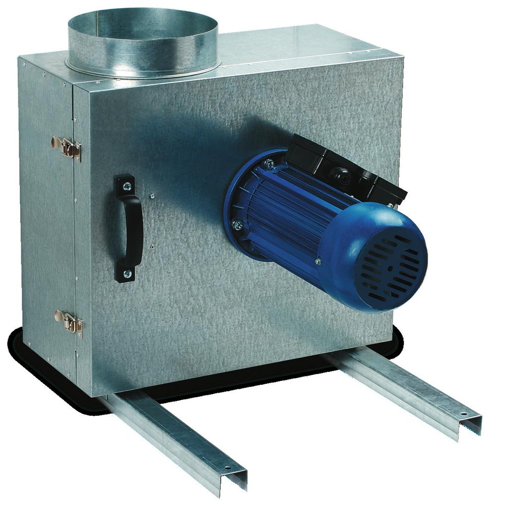
4 FAN DESIGN Exhaust spigot Centrifugal impeller Casing Electric motor Supporting mounting frame Vibration isolator Terminal box Fig. 1. fan design The steel is made of galvanized steel and is internally filled with 50 mm thermal- and sound-insulating layer made of non-flammable mineral wool. The fan casing is installed on a supporting mounting frame with integrated vibration isolators. The swivel motor-impeller block is attached to the swivel door which facilitates the fan servicing. The fan is equipped with a single- or three-speed motor with short circuit rotor and a centrifugal impeller with forward curved blades. The impeller is made of galvanized steel. The motor is equipped with ball bearings for longer service life and a dynamically balanced turbine. F class motor winding insulation and IP 54 ingress protection rating. Overheating protection by built-in thermal switches with leads for connection to external protection devices. Smooth or step-up speed control with an auto transformer or frequency inverter. Both available upon separate order. Mounting to the wall is performed with the mounting angle bracket KS-ISK (available upon separate order). DELIVERY SET fan - 1 item; operation manual - 1 item. ATTENTION Make sure the fan has no visible transport damages and check the ordered and the delivered goods for compliance. 4 _v.1(2)-en.indd :21:00
5 TECHNICAL DATA Table 1. Technical data Parameters 150 4E 160 4E 150 4D 160 4D 200 4E 200 4D 250 4E 250 4D Voltage, 50 Hz [V] 1 ~ ~ ~ ~ ~ ~ 380 Power [W] Current [A] Max. air flow [m 3 /h] RPM [min -1 ] Noise level, 3 m [dba] Max. transported air temperature [ C] Ingress Protection Rating IP 54 IP 54 IP 54 IP 54 IP 54 IP 54 Table 2. Overall dimensions Dimensions [mm] Type ØD B B1 H H1 L L1 L2 L3 L4 Weight [kg] 150 4E D E D E D E D L4 D L4 L3D H1 D H H1 B1 L2 B L1 L Fig. 2. fan overall dimensions 5 _v.1(2)-en.indd :21:01
6 MOUNTING AND OPERATION GUIDELINES WARNING Before starting mounting: Read carefully the fan mounting, start-up, operation and servicing instructions; Check the fan for possible transport damages. Follow the safety regulations during the fan start-up and operations. The fan is designed for connection to round air ducts on both sides of the fan. The special fixing brackets in the fan casing enable selecting the most suitable fan installation position. If the fan is connected through the flexible anti-vibration connectors the fan must be secured to a mounting surface with supports, hanger brackets or brackets. The air motion direction in the system must match the pointer on the fan casing. Install the fan to ensure sufficient and quick access for servicing and repair operations. The fan must be grounded. To reduce air turbulence related pressure losses connect a straight air duct to the fan of the length equal to min. 1 air duct diameter on the intake side and min. 3 air duct diameter on the exhaust side. Power is supplied either through the external terminal box. Mounting of the fan on the wall with the KS-ISK mounting angle brackets is shown in fig. 3 (available upon separate order). MOUNTING SEQUENCE 1. Cut off power supply. 4. Install the fan on the KS-ISK mounting brackets and fix it using appropriate fasteners. QF 2. Mark and drill the holes on the mounting surface for the fan mounting. 3. Fix the KS-ISK mounting angle brackets on a mounting bracket using appropriate fasteners, for example, expansion anchors. 5. Install accessories, i.e. install a backdraft damper into the fan spigot. 6. Connect air ducts to the fan and fix those with clamps (available upon separate order). 6 _v.1(2)-en.indd :21:01
7 CONNECTION TO POWER MAINS! WARNING Read the operation manual prior to any electric installations. Connection of the fan to power mains is allowed by a qualified electrician only. The rated electrical parameters of the fan are stated on the rating plate. No modifications of internal connections are allowed and will result in void warranty. Connect the fan only to power mains with valid electric standards. Follow the respective electric standards, safety rules (DIN VDE 0100), TAB der EVUs. The house cabling system must be equipped with an automatic switch at the external input. Connect the fan to power mains through the automatic switch. The contact gap on all poles at least 3 mm (VDE 0700 T / EN ). The automatic switch trip current must be in compliance with the fan current consumption, refer Table 1. Install the automatic switch to ensure prompt access. The fan is rated for connection to single-phase alternating current power mains 230 V / 50 Hz. The recommended rated automatic switch trip current for ISO-K fans is stated in Table 3. The electric connections must be performed with insulated, durable and heat-resistant conductors (cables, wires). The recommended conductor cross section is stated in Table 3. The wiring diagram for connection of the single-phased fans is shown in fig. 3. The wiring diagram for connection of the three-phased fans is shown in fig. 4. Cut power supply to the fan off by turning the automatic electric switch QF to OFF position. Take steps to prevent activation of the automatic switch prior to finishing mounting. Connection to power mains of the basic fan model with a terminal box is as follows: 1. Cut off power supply to the fan by turning the automatic switch QF to OFF position. 2. Remove the screws that fix the terminal box cover and take off the cover. Table 3. Recommended automatic switch trip current and cable cross section. Model Rated automatic switch trip current [A] Recommended cable n x S, n wire number; S cross section, mm E 2 2 x D 1 3 x E 2 2 x D 1 3 x E 8 2 x D x E x D 4 3 x 1.5 C1 ~230 V 50 Hz N L QF W2 U2 V2 X1 U1 V1 W1 3. Route the electric cable to the terminal box through the electric lead-in and connect the cable wires to the input terminal box in compliance with the wiring diagram, fig. 3, 4. Fix the cable with nuts. Re-install the terminal box cover and fix it with screws. X1 fan terminal block С1 capacitor QF automatic switch (not included into the delivery set) Fig. 3. Wiring diagram for single-phase fans W2 U2 V2 X1 U1 V1 W1 X1 fan terminal block QF automatic switch (not included into the delivery set) 4. Turn the fan on by turning the automatic switch QF to ON position. QF L1 L2 L3 ~380 V / 50 Hz Fig. 4. Wiring diagram for three-phase fans 7 _v.1(2)-en.indd :21:02
8 MAINTENANCE ATTENTION Cut power supply to the fan off by turning the automatic electric switch QF to OFF position. Take steps to prevent activation of the automatic switch prior to finishing maintenance. QF Disconnect the fan from power mains prior to any operations related to servicing and repair works. Make sure the rotating parts have come to a full stop. The fan technical maintenance consists in the periodic cleaning of the fan surfaces. The impeller blades required thorough cleaning once in 6 months. Cleaning procedure: cut off power supply to the fan; clean the impeller blades with a dry soft brush or compressed air. open the fan swivel panel; QF Avoid liquid dripping on the motor and inside the electronic compartment. While cleaning the fan be careful not to displace the impeller counter weights. After cleaning perform all the operations reverse. TROUBLESHOOTING Table 4. Error list and troubleshooting Fault Possible reason Remedy The fan does not operate. Automatic switch tripping. Noise, vibration. No power supply or connection error. Jammed motor, soiled impeller blades. Short circuit in power grid. The impeller is soiled. The screw connection is loose. No flexible anti-vibration connectors are installed. Make sure of correct power supply, otherwise troubleshoot the connection error. Remove the motor jam, clean the impeller blades. Turn the fan off and contact your seller for troubleshooting. Clean the impeller. Tighten the fastening screws. Install the flexible anti-vibration connectors. 8 _v.1(2)-en.indd :21:03
9 ACCEPTANCE CERTIFICATE Sound-insulated fan E 4D is recognizes as serviceable. The product complies with the requirements according to the EU norms and directives, to the relevant EU-Low Voltage Equipment Directives, EU-Directives on Electromagnetic Compatibility. We hereby declare that the product complies with the essential protection requirements of Electromagnetic Council Directive 2004/108/EC, 89/336/EEC and Low Voltage Directive 2006/95/EC, 73/23/EEC and CE-marking Directive 93/68/EEC on the approximation of the laws of the Member States relating to electromagnetic compatibility. This certificate is issued following test carried out on samples of the product referred to above. Approval mark Manufacturing date CONNECTION CERTIFICATE Sound-insulated fan E 160 4D is connected to power mains in compliance with this operation manual requirements by the professional: Company: Name: Date Signature WARRANTY CARD E 4D SELLER SALES DATE REPRESENTATIVE IN EU Blauberg Ventilatoren GmbH Aidenbachstr. 52a, D München, Deutschland 9 _v.1(2)-en.indd :21:03
10 10 NOTES _v.1(2)-en.indd :21:03
11 11 NOTES _v.1(2)-en.indd :21:03

12 / v.1 (2) / EN _v.1(2)-en.indd :21:03
INLINE СENTRIFUGAL FAN BOX BOX-R OPERATION MANUAL
 INLINE СENTRIFUGAL FAN BOX BOX-R OPERATION MANUAL CONTENT 3 Introduction 3 General 3 Safety rules 3 Storage and transportation rules 3 Manufacturer s warranty 4 Fan design 4 Delivery set 5 Technical data
INLINE CENTRIFUGAL FAN. Centro-M OPERATION MANUAL
 INLINE CENTRIFUGAL FAN OPERATION MANUAL www.blaubergventilatoren.de CONTENT 3 Introduction 3 General 3 Safety rules 3 Transport and storage requirements 3 Manufacturer's warranty 4 Fan design 4 Delivery
AXIS-QA G TUBO-M/MZ AXIAL FANS. Axis / Tubo OPERATION MANUAL
 TUBO-M/MZ AXIS-QA AXIS-Q TUBO-F AXIS-QR AXIS-F AXIS-QRA AXIS-QA G AXIAL FANS EN OPERATION MANUAL www.blaubergventilatoren.de CONTENT 3 Introduction 3 General 3 Safety rules 3 Transport and storage requirements
HEAT RECOVERY AIR HANDLING UNIT
 HEAT RECOVERY AIR HANDLING UNIT OPERATION MANUAL KOMFORT_L v2(2)_en.indd 1 07.08.2015 15:0:44 CONTENTS Introduction General Safety regulations Transportation and storage regulations Manufacturer's warranty
SINGLE-ROOM REVERSIBLE UNIT WITH HEAT AND HUMIDITY RECOVERY VENTO V50-1 OPERATION MANUAL
 SINGLE-ROOM REVERSIBLE UNIT WITH HEAT AND HUMIDITY RECOVERY VENTO V50-1 EN OPERATION MANUAL CONTENTS Introduction 3 General 3 Safety rules 3 Transportation and storage rules 3 Manufacturer's warranty 3
CENTRIFUGAL FAN IN SCROLL CASING. Helix S-Vent OPERATION MANUAL
 CENTRIFUGAL FAN IN SCROLL CASING Helix S-Vent EN OPERATION MANUAL Helix / S-Vent www.blaubergventilatoren.de CONTENTS CONTENTS 3 Introduction 3 Use 3 Delivery set 4 Technical data 10 Safety requirements
Turbo. Service Instructions
 Turbo Service Instructions E BAUBERG Company is happy to offer your attention a new highquality inline mixed-flow Blauberg Turbo fan. The solid team of highqualified professionals with many years of working
Wind. Service instruction
 Wind Service instruction E BAUBERG Company is happy to offer your attention the window axial Blauberg Wind fan. The solid team of high-qualified professionals with many years of working experience, technological
USER S MANUAL. VCU/VCUN Series CENTRIFUGAL FAN IN SCROLL CASING
 USER S MANUAL VCU/ Series CENTRIFUGAL FAN IN SCROLL CASING 2 CONTENTS Introduction Use Delivery set Designation key Technical data Safety requirements Design and operating logic Mounting and set-up Connection
Smart Smart IR. Service instruction SALES DATE MANUFACTURED ON (DATE): APPROVAL MARK SOLD. model (check applicable) is recognized as serviceable
: APPROVAL MARK SOLD. model (check applicable) is recognized as serviceable") Smart Smart IR model (check applicable) is recognized as serviceable Service instruction SALES DATE MANUFACTURED ON (DATE): SOLD APPROVAL MARK SMART-EN-04 BLAUBERG Company is happy to offer your attention
Smart Smart IR model (check applicable) is recognized as serviceable Service instruction SALES DATE MANUFACTURED ON (DATE): SOLD APPROVAL MARK SMART-EN-04 BLAUBERG Company is happy to offer your attention
SINGLE ROOM HEAT RECOVERY AIR HANDLING UNIT
 SINGLE ROOM HEAT RECOVERY AIR HANDLING UNIT EN OPERATION MANUAL www.blaubergventilatoren.de CONTENTS 3 Introduction 3 General 3 Safety rules 3 Transportation and storage rules 3 Manufacturer's warranty
Aero. Service Instructions
 Aero ervice Instructions E BAUBERG Company is happy to offer your attention a new generation product, the BAUBERG Aero fan. The solid team of highqualified professionals with many years of working experience,
USER S MANUAL. VKP Series INLINE FAN
 USER S MANUAL Series INLINE FAN 2 CONTENTS Safety requirements 3 Introduction 5 Use 5 Delivery set 5 Designation key 5 Technical data 5 Design and operating logic 8 Mounting and set-up 8 Connection to
РУКОВОДСТВО USER ПО MANUAL ЭКСПЛУАТАЦИИ CENTRIFUGAL INLINE FANS VKM / VKMZ / VC SERIES
 РУКОВОДСТВО USER ПО MANUAL ЭКСПЛУАТАЦИИ CENTRIFUGAL INLINE FANS / Z / VC SERIES 2 / z / VC CONTENT Use Delivery set Structural designation key Main technical data Safety requirements Fan design Connection
SOUND-INSULATED FAN. Iso-B OPERATION MANUAL
 SOUND-INSULATED FAN Iso-B EN OPERATION MANUAL Iso-B www.blaubergventilatoren.de CONTENTS Safety requirements... 3 Introduction... 5 Purpose... 5 Delivery set... 5 Technical data... 6 Design and operating
AXIAL FANS USER S MANUAL
 AXIAL FANS USER S MANUAL WARNING! Disconnect the fan from power supply prior to any connection, servicing and repair operations. Only duly qualified electricians with valid electrical permit for electric
USER S MANUAL. Centrifugal inline fan. VKMz 100 Q VKMz 100 VKMz 125 Q VKMz 125. VKMz 250 Q VKMz 250 VKMz 315 Q VKMz 315
 USER S MANUAL VKMz 100 Q VKMz 100 VKMz 125 Q VKMz 125 VKMz 150 VKMz 160 VKMz 200 Q VKMz 200 VKMz 250 Q VKMz 250 VKMz 315 Q VKMz 315 Centrifugal inline fan VKMz CONTENTS Contents... 2 Safety requirements...
OPERATION MANUAL CENTRIFUGAL INLINE FAN WITH ELECTRONICALLY COMMUTATED MOTOR VKM EC SERIES. F88EN-02.indd :07:11
 OPERATION MANUAL CENTRIFUGAL INLINE FAN WITH ELECTRONICALLY COMMUTATED MOTOR VKM EC SERIES F88EN-02.indd 1 04.09.2015 8:07:11 2 VKM ЕС CONTENT Introduction Use Structural designation key Delivery set Main
DUCT COOLERS KWK KFK OPERATION MANUAL. KWK_KFK_v2(4)_EN.indd :35:29
_EN.indd :35:29") DUCT COOLERS KWK KFK EN OPERATION MANUAL KWK_KFK_v2(4)_EN.indd 1 13.06.2016 13:35:29 CONTENTS 3 Introduction 3 General 3 Safety rules 3 Transportation and storage regulations 3 Manufacturer s warranty
DUCT COOLERS KWK KFK EN OPERATION MANUAL KWK_KFK_v2(4)_EN.indd 1 13.06.2016 13:35:29 CONTENTS 3 Introduction 3 General 3 Safety rules 3 Transportation and storage regulations 3 Manufacturer s warranty
Calm. Service Instructions
 Calm E ervice Instructions BAUBERG VETIATORE GmbH is happy to offer you a new generation product, the BAUBERG Calm fan. The solid team of high-qualified professionals with many years of working experience,
CENTRIFUGAL FANS user's manual. model VENTS VK.
 EN CENTRIFUGAL FANS user's manual model VENTS VK www.ventilation-system.com 2013 EN! WARNING! Disconnect the fan from power mains prior to any connection, servicing and repair operations. Mounting and
AXIAL FAN User s manual. Quiet-dMEV 100 DC.
 AXIAL FAN User s manual Quiet-dMEV 100 DC www.ventilation-system.com CONTENTS Delivery set... 6 Brief description... 6 Operating guidelines... 6 Designation key... 7 Installation and set-up... 7 Fan options...
Centrifugal inline fans
 USER S MANUAL VKM 100 Q VKM 100 VKM 125 Q VKM 125 VKM 150 E VKM 150 VKMS 150 VKM 160 VKMS 160 VKM 200 VKMS 200 VKM 250 E VKM 250 VKM 315 VKMS 315 VKM 355 Q VKM 400 VKM 450 Centrifugal inline fans VKM CONTENTS
INTELLIGENT AXIAL FAN user's manual
 ACCEPTANCE CERTIFICATE The fan is duly recognized as serviceable. ifan Approval mark Manufactured on (date) Sold (name and stamp of the trade company) INTELLIGENT AXIAL FAN user's manual model VENTS ifan
CENTRIFUGAL CEILING EXTRACT FAN
 CENTRIFUGAL CEILING EXTRACT FAN 110 Т/H/IR 110 Light Т/H/IR 150 Т/H/IR 150 Light Т/H/IR EN USER'S MANUAL CONTENTS Contents... 2 Safety requirements... 2 Purpose... 4 Delivery Set... 4 Designation key...
USER S MANUAL NKP. Duct heater for supply air pre-heating with external control
 USER S MANUAL Duct heater for supply air pre-heating with external control CONTENTS Contents... 2 Safety requirements... 2 Purpose... 4 Delivery set... 4 Designation key... 4 Technical data... 5 Design
CENTRIFUGAL CEILING EXTRACT FAN
 CENTRIFUGAL CEILING EXTRACT FAN Ceileo 200/250/300 Ceileo 200/250/300 Т/H/IR Ceileo 200/250/300 Light Ceileo 200/250/300 Light Т/H/IR EN USER'S MANUAL CONTENTS Safety requirements... 2 Purpose... 4 Delivery
HEAT RECOVERY AND HEAT AND HUMIDITY RECOVERY AIR HANDLING UNIT
 HEAT RECOVERY AND HEAT AND HUMIDITY RECOVERY AIR HANDLING UNIT S S11 Series SB S11 Series SB -E S11 Series SB -E S11 Series EN OPERATION MANUAL CONTENTS Safety requirements... 2 Purpose... 4 Delivery set...
HEAT RECOVERY AIR HANDLING UNITS
 HEAT RECOVERY AIR HANDLING UNITS KOMFORT EC DB S11 KOMFORT EC DB S15 EN OPERATION MANUAL KOMFORT_EC_DB_S11(15)_v2(2-4)_ENG.indd 1 06.08.2015 14:30:31 CONTENTS 3 Introduction 3 General 3 Safety regulations
Axial intelligent fan USER S MANUAL
 Axial intelligent fan USER S MANUAL CONTENTS Delivery set... 6 Technical data... 6 Installation and set-up... 9 Connection to power mains... 11 Operation guidelines... 11 Unit control... 12 Storage and
HEAT RECOVERY AIR HANDLING UNITS KOMFORT EC S S11/S15 KOMFORT EC SB S11/S15
 HEAT RECOVERY AIR HANDLING UNITS KOMFORT EC S S11/S15 KOMFORT EC SB S11/S15 EN OPERATION MANUAL KOMFORT EC S/SB www.blaubergventilatoren.de CONTENTS 3 Introduction 3 General 3 Safety regulations 3 Transportation
INLINE MIXED FLOW FANS IN SOUND INSULATED CASING VENTS TT SILENT M USER MANUAL
 IIE MIED FOW FAS I SOUD ISUATED CASIG VETS TT SIET M USER MAUA www.ventilation-system.com 2013 ! WARIG Disconnect the fan from power mains prior to any connection, servicing and repair operations. Mounting
INLINE MIXED-FLOW FANS VENTS TT SERIES USER'S MANUAL.
 IIE MIXED-FOW FAS VETS TT SERIES USER'S MAUA www.ventilation-system.com 2011 Read this manual carefully before installation and commissioning of the unit.! READ THE ISTRUCTIOS CAREFUY TO REDUCE THE RISK
AXIAL FANS user's manual. model Quiet
 E AXIA FA user's manual model Quiet 0 ! WARIG Disconnect the fan from power mains prior to any connection, servicing and repair operations. Mounting and maintenance are allowed for duly qualified electricians
AIR HANDLING UNIT WITH HEAT RECOVERY
 AIR HANDLING UNIT WITH HEAT RECOVERY Freshbox 100 EN OPERATION MANUAL Freshbox 100 www.blaubergventilatoren.de CONTENTS Safety requirements... 2 Purpose... 4 Delivery set... 4 Designation key... 4 Technical
USER'S MANUAL INLINE CENTRIFUGAL FANS IN SOUND-INSULATED CASING VS, VS EC SERIES
 USER'S MAUA IIE CETRIFUGA FAS I SOUD-ISUATED CASIG VS, VS EC SERIES PURPOSE The inline centrifugal fan VS / VS EC enclosed in a sound-insulated casing with the intake spigot diameter from up to 70 mm,
HEAT RECOVERY VENTILATOR
 HEAT RECOVERY VENTILATOR HRV H 00 ERV H 00 HRV H 300 ERV H 300 EN OPERATION MANUAL HRV /ERV H 00(300) www.blaubergventilatoren.de CONTENTS Application... Delivery set...3 Unit designation key...3 Basic
Air handling unit. BlauAir RH USER S MANUAL
 Air handling unit EN USER S MANUAL CONTENTS Safety requirements... 2 Purpose... 4 Delivery set... 4 Designation key... 4 Technical data... 5 Unit design and operation logic... 7 Installation and set-up...
USER S MANUAL. Heat Recovery Ventilator. Vents Brig HRV 200 Vents Brig HRV 300
 USER S MANUAL Heat Recovery Ventilator Vents Brig HRV 200 Vents Brig HRV 300 2 Brig HRV 200 (300) CONTENT Introduction... 3 Application... 3 Delivery set... 3 Unit designation key... 4 Basic unit dimensions...
USER'S MANUAL PS
 USER'S MANUA 067-0. PS ROOF FANS VENTS VKV \ VKH \ VKV EC \ VKH EC \ VKMK \ VKMKp \ VOK \ VOK SERIES VKV, VKH, VKV EC, VKH EC, VKMK, VKMKp, VOK, VOK CONTENT. Application р.. Delivery set р.. Designation
AXIAL DOMESTIC FANS. User manual LARUS LIBELLA FENESO CYCNUS CICONUS SIGILA SIGILA MOTION
 AXIAL DOMESTIC FANS User manual LARUS LIBELLA FENESO CYCNUS CICONUS SIGILA SIGILA MOTION SAFETY REQUIREMENTS Disconnect the fan from power mains prior to any connection, servicing and repair operations.
USER S MANUAL. Heat (Energy) Recovery Ventilator. Vents Frigate HRV 120 S Vents Frigate ERV 120 S
 Recovery Ventilator. Vents Frigate HRV 120 S Vents Frigate ERV 120 S") USER S MANUAL Heat (Energy) Recovery Ventilator Vents Frigate HRV 120 S Vents Frigate ERV 120 S 2 Frigate HRV(ERV) 120 S CONTENT Introduction... 3 Application... 3 Delivery set... 3 Unit designation key...
USER S MANUAL Heat (Energy) Recovery Ventilator Vents Frigate HRV 120 S Vents Frigate ERV 120 S 2 Frigate HRV(ERV) 120 S CONTENT Introduction... 3 Application... 3 Delivery set... 3 Unit designation key...
USER'S MANUAL. Single-room reversible energy regeneration ventilator. TwinFresh R-50 TwinFresh RA-50 TwinFresh R-50-2 TwinFresh RA-50-2
 USER'S MANUAL TwinFresh R-50 TwinFresh RA-50 TwinFresh R-50-2 TwinFresh RA-50-2 TwinFresh S-60 TwinFresh SA-60 TwinFresh S-60-2 TwinFresh SA-60-2 TwinFresh S-50 TwinFresh SA-50 TwinFresh S-50-2 TwinFresh
Installation manual Mini Comfort 50 S/L 07/ V EN
 Installation manual Mini Comfort 50 S/L 07/2015 - V 1.1 - EN www.veneco-ventilation.be Veneco ventilation by Elek Trends Productions nv Blauwfazantjesstraat 4 B - 7700 Moeskroen Tel. +32 (0)56 48 15 90
USER S MANUAL VUT 160 P2B EC A14 VUT 160 PB EC A14 VUT 350 P2B EC A14 VUT 350 PB EC A14 HEAT RECOVERY AIR HANDLING UNIT
 USER S MANUAL VUT 160 P2B EC A14 VUT 160 PB EC A14 VUT 350 P2B EC A14 VUT 350 PB EC A14 HEAT RECOVERY AIR HANDLING UNIT 2 CONTENTS. Safety requirements... 3 Introduction.........................................................
USER S MANUAL VUT V(B) EC А14 VUE V(B) EC А14. Heat/heat and humidity recovery air handling unit
 EC А14 VUE V(B) EC А14. Heat/heat and humidity recovery air handling unit") USER S MANUAL VUT V(B) EC А14 VUE V(B) EC А14 Heat/heat and humidity recovery air handling unit CONTENTS Safety requirements... 2 Purpose... 4 Delivery set... 4 Designation key... 4 Technical data... 5
USER S MANUAL VUT V(B) EC А14 VUE V(B) EC А14 Heat/heat and humidity recovery air handling unit CONTENTS Safety requirements... 2 Purpose... 4 Delivery set... 4 Designation key... 4 Technical data... 5
VUT 350 H VUT 500 H VUT 530 H VUT 600 H VUT 1000 H VUT 2000 H HEAT RECOVERY AIR HANDLING UNIT
 РУКОВОДСТВО USER S MANUAL ПОльзователя VUT 350 H VUT 500 H VUT 530 H VUT 600 H VUT 1000 H VUT 2000 H HEAT RECOVERY AIR HANDLING UNIT 2 CONTENTS Safety requirements 3 Introduction 5 Use 5 Delivery set 5
USER S MANUAL DN-2. Drain pump
 USER S MANUAL DN-2 CONTENTS Safety requirements... 2 Purpose... 3 Delivery set... 3 Technical data... 3 Design... 4 Installation and set-up... 5 Connection to power mains... 8 Storage and transportation
USER MANUAL. Air handling unit with heat recovery. VUT 300 EVK mini EC VUT 300 EV mini EC VUT 301 EVK mini EC VUT 301 EV mini EC
 USER MANUAL Air handling unit with heat recovery VUT 300 EVK mini EC VUT 300 EV mini EC VUT 301 EVK mini EC VUT 301 EV mini EC 2 CONTENTS Introduction Use Delivery set Structural designation key Technical
Turbo Inline Fan, White - Non Illuminated Art no.33500
 Quality Bathroom Products Turbo Inline Fan, White - Non Illuminated Art no.33500 Turbo Inline Fan, White - Cool White LED Art no.300 Turbo Inline Fan, White - Warm White LED Art no.34000 Turbo Inline Fan,
White - Non Illuminated Art no White - Cool White LED Art no.32600
 Cyclone Inline Fans White - Non Illuminated Art no.33300 White - Cool White LED Art no.32600 White - Warm White LED Art no.33800 Chrome - Non Illuminated Art no.33400 Chrome - Cool White LED Art no.32700
USER S MANUAL AiR duct heater with integrated temperature control UNit or A control UNit
 USER S MANUAL Air duct heater with integrated temperature control unit or a control unit 2 CONTENTS Safety requirements 3 Introduction 5 Use 5 Delivery set 5 Designation key 5 Main technical parameters
Issue5 07/13 USERS MANUAL IN-LINE MIXED FLOW
 90411215-Issue5 07/13 USERS MANUAL IN-LINE MIXED FLOW DESTINATION The in-line mixed flow fans with channels' diameters ranging from 100 to 150 mm are designed for installation in the ventilating systems
USER S MANUAL BUCKET FAN SERIES BUCKET FAN WHISPER SERIES
 USER S MANUAL BUCKET FAN SERIES BUCKET FAN WHISPER SERIES Bucket Fan 420 Bucket Fan 1055 Bucket Fan 1460 420 1055 1460 2 Bucket Fan CONTENT INTRODUCTION 3 USE 3 WHAT S INCLUDED IN THE BOX 3 DESIGNATION
IDE 20 / IDE 30 / IDE 50 IDE 60 / IDE 80
 IDE 20 / IDE 30 / IDE 50 IDE 60 / IDE 80 EN OPERATING MANUAL OIL HEATER TRT-BA-IDE20-30-50-60-80-TC-001-EN Table of contents Information on the use of this manual... 1 Scope of delivery... 1 General safety...
KOMFORT EC DB Suspended heat recovery air handling units
 2018 AIR HANDLING UNITS KOMFORT EC DB Suspended heat recovery air handling units Features Air handling units for efficient supply and exhaust ventilation in flats, houses, cottages and other buildings.
USER MANUAL. Frigate HRV 120 SR Frigate ERV 120 SR. Heat (energy) recovery ventilation unit
 recovery ventilation unit") USER MANUAL Frigate HRV 120 SR Frigate ERV 120 SR Heat (energy) recovery ventilation unit 2 CONTENTS Safety requirements... 3 Introduction... 5 Use... 5 Included in the box... 5 Designation key... 5 Technical
USER MANUAL Frigate HRV 120 SR Frigate ERV 120 SR Heat (energy) recovery ventilation unit 2 CONTENTS Safety requirements... 3 Introduction... 5 Use... 5 Included in the box... 5 Designation key... 5 Technical
CANOPY RANGEHOOD. instruction manual V3FC60SS & V3FC90SS 12 MONTH WARRANTY
 CANOPY RANGEHOOD instruction manual V3FC60SS & V3FC90SS 12 MONTH WARRANTY Contents Guide to the Appliance 2 Caring for the Environment 3 Safety Information and Warnings 4 Installation Instructions 6 Operation
Lo-Carbon MULTIVENT MVDC-MS & MVDC-MS H VENTILATION SYSTEMS V~50Hz. Installation and Wiring Instructions IP22. Stock Ref.
 Lo-Carbon MULTIVENT MVDC-MS & VENTILATION SYSTEMS Installation and Wiring Instructions Stock Ref. N MVDC-MS 76A 98 0-0V~50Hz PLEASE READ INSTRUCTIONS IN CONJUNCTION WITH THE ILLUSTRATIONS. PLEASE SAVE
READ AND SAVE THESE INSTRUCTIONS READ CAREFULLY BEFORE ATTEMPTING TO ASSEMBLE, INSTALL, OPERATE OR MAINTAIN THE PRODUCT DESCRIBED. PROTECT YOURSELF AN
 READ AND SAVE THESE INSTRUCTIONS READ CAREFULLY BEFORE ATTEMPTING TO ASSEMBLE, INSTALL, OPERATE OR MAINTAIN THE PRODUCT DESCRIBED. PROTECT YOURSELF AND OTHERS BY OBSERVING ALL SAFETY INFORMATION. FAILURE
Series VENTS VUT R WH ЕС
 AIR HANDLING UNITS WITH HEAT RECOVERY Series VENTS EH ЕС Series VENTS WH ЕС Air handling units with the air capacity up to 1500 m 3 /h in soundand heat-insulated casing with integrated electric heater.
KOMFORT EC S5B KOMFORT EC D5B KOMFORT EC S. Heat and Energy Recovery Ventilators
 KOMFORT EC S5B KOMFORT EC D5B KOMFORT EC S Heat and Energy Recovery Ventilators 2018 AIR HANDLING UNITS 2 CONTENT KOMFORT EC S5B270(-E) 4 KOMFORT EC D5B1(-E) 8 KOMFORT EC S(B)(-E) 12 AIR HANDLING UNITS
VENTS КАМ. Series CHIMNEY CENTRIFUGAL FANS
 CHIMNEY CENTRIFUGAL FANS Series Design The fan casing is made of galvanized steel and equipped with heat- and sound insulation of fireresistant mineral wool. The casing is perforated for the internal air
ISCG90SS _03 ISCG90SS
 ISCG90SS 60900355_03 ISCG90SS GB IE [01] x 1 [02] x 1 [03] x 1 [04] x 8 [05] x 1 [06] x 4 [07] x 1 [08] x 1 [09] x 1 [10] x 4 [11] x 4 [12] x 1 [13] x 4 (6x70mm) [14] x 8 (6.3x17x2mm) 1 : 1 [15] x 4 (3.9x18mm)
Series. Suspended air supply units with the air capacity up to 4100 m 3 /h in the sound- and heat-insulated casing with the water heater
 SUPPLY UNITS Series VENTS PA E Series VENTS PA W A13 control panel A13 control panel Suspended air supply units with the air capacity up to 3350 m 3 /h in the sound- and heat-insulated casing with the
Inline mixed-flow fans with the air capacity up to 450 m 3 /h
 FANS FOR ROUND DUCTS Series VENTS ТТ PRO Series VENTS ТТ perform required servicing. All the models may be equipped with a regulated timer with turn-off delay adjustable from 2 to 30 min. TT PRO design
INSTALLATION AND USER S MANUAL COOKER HOOD RS-600/A-S
 INSTALLATION AND USER S MANUAL COOKER HOOD RS-600/A-S RS-600 (CHS60SS)-GB-05.indd 1 6/8/2010 9:30:59 AM TABLE OF CONTENTS 1. Introduction 2 2. Safety precaution 2 3. Intended use 3 4. Parts supplied 3
KKKKKKKCOOKER HOOD INSTRUCTION MANUAL
 KKKKKKKCOOKER HOOD INSTRUCTION MANUAL Read this manual carefully before operation Pictures in this manual are for reference only, the product in kind prevail. E60MEW2M19 Contents 01 02 03 04 05 06 07 08
Inline mixed-flow fans with the air capacity up to 1850 m 3 /h
 FANS FOR ROUND DUCTS Series VENTS ТТ PRO Series VENTS ТТ perform required servicing. All the models may be equipped with a regulated timer with turn-off delay adjustable from 2 to 30 min. TT PRO design
USER S OPERATION MANUAL HL-RD 2000 E EC HL-RD 3000 E ЕС
 USER S OPERATION MANUAL HL-RD 2000 E EC HL-RD 3000 E ЕС Air handling unit with heat recovery 2 CONTENT Introduction Use Delivery set Structural designation key Technical data Safety precautions Structure
UNDERMOUNT RANGEHOOD. instruction manual VPP52S & VPP90S 12 MONTH WARRANTY
 UNDERMOUNT RANGEHOOD instruction manual VPP52S & VPP90S 12 MONTH WARRANTY Contents Guide to the Appliance 2 Caring for the Environment 3 Safety Information and Warnings 4 Installation Instructions 6 Operation
Centrif Duo & Centrif Duo Plus
 Centrif Duo & Centrif Duo Plus Installation and Wiring Instructions Stock Ref. N Centrif Duo P 25 61 20D Centrif Duo T 25 62 20D Centrif Duo DP 25 63 20D Centrif Duo HTP 25 64 20D Centrif Duo Centrif Duo
Series VENTS MPA...W. Supply units with the air capacity up to 6500 m 3 /h in the compact sound- and heat-insulated casing with water heater
 SUPPLY UNITS Series Series LCD control panel SAS908 control panel Supply units with the air capacity up to 3500 m 3 /h in the compact sound- and heat-insulated casing with electric heater Supply units
ART cm Island Curved Glass
 ART28101 90cm Island Curved Glass [01] x 1 [02] x 1 [03] x 1 [04] x 1 [05] x 4 [06] x 1 [07] x 1 [08] x 1 [09] x 4 [10] x 4 [11] x 1 [12] x 4 (6x70mm) [13] x 4 (6.3x17x2mm) [14] x 8 (4x12x1mm) [15] x 4
Operating instructions
 ebm-papst Mulfingen GmbH & Co. KG Bachmühle D-74673 Mulfingen Phone +49 (0) 793-0 Fax +49 (0) 793-0 info@de.ebmpapst.com www.ebmpapst.com CONTENTS. SAFETY REGULATIONS AND NOTES. Levels of hazard warnings.
Installation and Maintenance Novax Smoke Exhaust Fan Type ACN Smoke
 918149-0 GB Installation and Maintenance Novax Smoke Exhaust Fan Type ACN Smoke 1. Application 2. Handling 2.1 Marking 2.2 Weight 2.3 Transport 3. Storage 4. Installation 4.1 Prior to attachment 4.2 Attachment
Cooker Hood User Manual
 Cooker Hood User Manual HCB93042X EN 01M-8850803200-0116-02 Please read this manual first! Dear Customers! Thank you for preferring a Beko product. We hope that you get the best results from your product
Acquaer Ltd. H-4900, Fehérgyarmat, Szatmári út 11. CENTRIFUGAL PUMP Instruction Manual ACm60 / ACm75 / ACm150 / ACm150B2
 CENTRIFUGAL PUMP Instruction Manual ACm60 / ACm75 / ACm150 / ACm150B2 Congratulations on your purchase of a LEO Centrifugal Pump It is important that you read, fully understand and observe the following
ACN SMOKE INSTALLATION AND MAINTENANCE
 NovAx ACN SMOKE INSTALLATION AND MAINTENANCE 918149-0 English 918149-0 GB Installation and maintenance NovAx smoke exhaust fan type ACN smoke 1. Application 2. Handling 2.1 Marking 2.2 Weight 2.3 Transport
Lo-Carbon Quadra Centrifugal Fan
 Lo-Carbon Quadra Centrifugal Fan Installation and Wiring Instructions Stock Ref. N Quadra TP Quadra TM Quadra HTP 439251A 439253A 439181A 220-240V~50Hz IPX4 PLEASE READ INSTRUCTIONS IN CONJUNCTION WITH
F17W44_MFB_F_EN INSTALLATION INSTRUCTIONS
 F17W44_MFB_F_EN INSTALLATION INSTRUCTIONS Contents Page User instructions 3-5 General 3 Fan installation 3-4 Maintenance 3 Electrical installation 5 Troubleshooting 5 Technical description 6-8 General
HEATING AND COOLING DEVICE AGC
 GDYNIA HEATING AND COOLING DEVICE - AGC 2013 1/8 HEATING AND COOLING DEVICE AGC SERVICE phone.: (+48 58) 783 99 50/51 Fax: (+48 58) 783 98 88 mobile: (+48) 510 098 081 E-mail: serwis@klimor.pl GDYNIA,
Operating Instruction Centrifugal fans without scroll (Translation of the Original) BA-RLE-AC /2014 RLE RLA
 BA-RLE-AC /2014 RLE RLA") Operating Instruction Centrifugal fans without scroll (Translation of the Original) EN RLE RLA Content 1. Important information 2. Safety notes 3.Technical description 4. Transport 5. Mounting / Installation
Operating Instruction Centrifugal fans without scroll (Translation of the Original) EN RLE RLA Content 1. Important information 2. Safety notes 3.Technical description 4. Transport 5. Mounting / Installation
FLUEBOOST. flueboost 350 gas fire model
 350 FLUEBOOST flueboost 350 gas fire model The flueboost is a box shaped unit with in line spigots for the flue connection, a pressure switch to ensure safe operation and plug-in electrical fittings for
Operating instructions
 Operating instructions (Translation of the original operating instructions) Type TEKA FILTERCUBE-MV TEKA Absaug- und Entsorgungstechnologie GmbH Industriestraße 13 D-46342 Velen Postfach 1137 D-46334 Velen
FAITH (dmev) 230V / 24V DC SELV Flush Mounted Domestic Continuous Extract Fans
 230V / 24V DC SELV Flush Mounted Domestic Continuous Extract Fans") FAITH (dmev) 230V / 24V DC SELV Flush Mounted Domestic Continuous Extract Fans Installation and Maintenance IPX4* The EMC Directive 2014/30/EU The Low Voltage Directive 2014/35/EU 1.0 SAFETY INFORMATION
FAITH (dmev) 230V / 24V DC SELV Flush Mounted Domestic Continuous Extract Fans Installation and Maintenance IPX4* The EMC Directive 2014/30/EU The Low Voltage Directive 2014/35/EU 1.0 SAFETY INFORMATION
AERO SERIES CEILING FAN
 AERO SERIES CEILING FAN INSTALLATION OPERATION MAINTENANCE WARRANTY INFORMATION CAUTION READ INSTRUCTIONS CAREFULLY FOR SAFE INSTALLATION AND FAN OPERATION. V.0 published on 2. 206 THANK YOU FOR PURCHASING
FRESHBOX 100. Single-room heat recovery unit. Air capacity up to 100 m³/h Heat recovery efficiency up to 96 %
 FRESHBOX 100 Single-room heat recovery unit Air capacity up to 100 m³/h Heat recovery efficiency up to 96 % FRESHBOX 100 CONTENTS FRESHBOX 100 FEATURES 3 DESIGN 4 OPERATING PRINCIPLE 6 CONTROL 6 APPLICATION
IN-LINE CENTRIFUGAL FAN VENTS VKP PS 125. User`s manual.
 IN-LINE CENTRIFUGAL FAN VENTS VKP PS 125 EN User`s manual www.vents-us.com EN READ AND SAVE THESE INSTRUCTIONS WARNING! TO REDUCE THE RISK OF FIRE, ELECTRIC SHOCK AND PERSONAL INJURY, READ AND UNDERSTAND
ELTA FANS IN-LINE MIXED FLOW FAN IMF100 / 125 / 150 / 200 INCLUDING MODELS WITH BUILT-IN-RUN-ON TIMERS T
 ELTA FANS IN-LINE MIXED FLOW FAN IMF100 / 125 / 150 / 200 INCLUDING MODELS WITH BUILT-IN-RUN-ON TIMERS T Installation and Maintenance Instructions. THESE INSTRUCTIONS MUST BE READ FULLY BEFORE COMMENCING
GLEB Kitchen exhaust fan
 GLEB Kitchen exhaust fan Installation and Maintenance??.1.2013 Contents 1. Important information 2. Safety notes 3. Technical description 4. Transport 5. Mounting instructions 6. Commissioning 7. Maintenance
Stainless Steel Chimney Extractor
 Stainless Steel Chimney Extractor User & Installation Guide LAM2404 LAMONA Appliances Dear Customer, Congratulations on your choice of a LAMONA domestic appliance which has been designed to give you excellent
Series VUT PW EC. wool internal heat and sound-insulating layer for VUT PE/PW 350, 600, 1000 units and 50 mm for VUT PE/PW 200, 3000 units.
 AIR HANDLING UNITS WITH HEAT RECOVERY Series VUT PE EC Series SAS908 control panel SAS908 control panel Ceiling mounted energy saving Air Handling Units (AHU) with the air capacity up to 4000 m 3 /h and
Box60/ 70/ 90. Box60_70_90 v8
 Box60/ 70/ 90 Box60_70_90 v8 GB IE [01] x 1 [02] x 2 [03] x 1 [04] x 2 [05] 60cm, 70cm x 2 90cm x 3 [06] x 1 [07] x 1 1 : 1 [09] x 6 (3.9 x 32mm) [08] x 6 [10] x 4 (3.4 x 10mm) Box60/ 70/ 90 GB IE Cooker
BESF Box Ventilator. Installation & Operating Manual USA CAN READ AND SAVE THESE INSTRUCTIONS
 Installation & Operating Manual 3001806 03.02 USA CAN BESF Box Ventilator READ AND SAVE THESE INSTRUCTIONS 1200 Northmeadow Parkway, STE 180 Roswell, GA 30076 (770) 587-3238 (800) 255-2923 Fax (770) 587-4731
e Bath Fan with Light User s Guide
 e Bath Fan with Light User s Guide abfl100rnl, BFL125RNL Item Stock Number(s): BFL100RNL, BFL125RNL IMPORTANT INSTRUCTIONS - OPERATING MANUAL READ AND SAVE THESE INSTRUCTIONS READ CAREFULLY BEFORE ATTEMPTING
ENGLISH INSTALLATION AND USER S MANUAL FRENCH NOTICE D INSTALLATION ET D UTILISATION ITALIAN MANUALE D ISTRUZIONE
 ENGLISH INSTALLATION AND USER S MANUAL FRENCH NOTICE D INSTALLATION ET D UTILISATION ITALIAN MANUALE D ISTRUZIONE 1 INSTALLATION AND USER S MANUAL CONTENT INTRODUCTION 03 SAFETY PRECAUTION 03 SPECIFICATION
IMPORTANT INSTRUCTIONS - OPERATING MANUAL
 IMPORTANT INSTRUCTIONS - OPERATING MANUAL Models: AK80LSL, AK100LSL Exhaust Fan READ AND SAVE THESE INSTRUCTIONS READ CAREFULLY BEFORE ATTEMPTING TO ASSEMBLE, INSTALL, OPERATE OR MAINTAIN THE PRODUCT DESCRIBED.
100cm Chimney Hood GB IE
 100cm Chimney Hood GB IE [01] x 1 [02] x 2 [03] x 2 [04] x 2 [05] x 3 [06] x 1 [07] x 1 1 : 1 [09] x 8 (3.9 x 32mm) [08] x 8 [10] x 4 (4 x 12mm) 100cm Chimney Hood GB IE Cooker Hood 04 FR Hotte Aspirante
Item:89522 P.1.
 Item:89522 P.1 www.qazqa.com 1. Warning symbols Read the instructions Caution Lamp 2. General Safety Instructions Read this instruction manual thoroughly before using the appliance and save it for future