Technical Manual. Operation and installation cooling units PKS 3000 SERIES 115V / 230V / 460V. Version 1.0, March 2018
|
|
|
- Bryce Horn
- 5 years ago
- Views:
Transcription


1 Technical Manual Operation and installation cooling units PKS 3000 SERIES 115V / 230V / 460V Version 1.0, March 2018
2 Preface The skills and information provided in the ORIGINAL OPERATING MANUAL are required for assembly and safe operation of Pfannenberg cooling units. The information is presented in a brief, clearly arranged format. The chapters are numbered throughout. If you have the operating manual in digital format, the links are interactive. Various unit types are documented in this operating manual. Pfannenberg cooling units are subject to continuous improvement. Please understand that we reserve the right to make changes to the design, equipment and technology. For this reason, no claims to specific features of the unit can be derived from the content of this operating manual. Safety Instructions and Symbols DANGER Identifies an exceptionally hazardous situation. Severe, irreversible injuries or death will occur if this notice is not observed. DANGER Identifies an exceptionally hazardous situation in connection with electrical voltage. Severe, irreversible injuries or death will occur if this notice is not observed. WARNING Identifies an exceptionally hazardous situation. Severe, irreversible or deadly injuries could occur if this notice is not observed. CAUTION Identifies a hazardous situation. Minor or moderate injuries could occur if this notice is not observed. NOTICE Notice is used to address practices not related to physical injury. Digital operating manual: If you have the operating manual in digital format, the links are interactive. Clicking on links takes you to the target text position. The table of contents is also interactive. The key combination ALT f brings you back to the starting point. Page 2 OPERATING MANUAL PKS Return To Table Of Contents
3 Table of contents 1 : INTENDED USE 1.1 General overview Duty of the operator : UNIT DESCRIPTION 2.1 Description of use Scope of delivery Order options Functional description Air flow functional principle Temperature Regulation Safety Concept Type plate Technical data and spare parts : ASSEMBLY AND INITIAL COMMISSIONING 3.1 Transport Storage Unpacking Assembly General assembly requirements PKS cooling unit assembly (side attachment) Electrical connection Standard controller (SC) electrical circuit diagram Door contact switch Mains supply connection : OPERATION 4.1 General functions Operation of the cooling unit : SERVICE AND MAINTENANCE 5.1 General cleaning Maintenance Maintenance checklist template Decommissioning : TROUBLESHOOTING : ACCESSORIES : TERMS OF WARRANTY Return To Table Of Contents OPERATING MANUAL PKS Page 3
4 1 : INTENDED USE 1.1 General overview The Pfannenberg attachment and installation cooling units of the PKS series are stationary cooling units for the dissipation of heat from switch cabinets. The cooling units have different cooling outputs. For exact specifications power consumption, see Technical data. Use of aluminum filters, fleece filters and fluted filters is possible with an additional adapter. The cooling units are available with thermostat controllers. These controllers are regulating units for the adjustment of refrigeration functions and operating data. For detailed specifications for the controller, see Technical data and Operation. All Pfannenberg cooling units are ROHS-compliant and free from: Silicone connections PCT, asbestos, formaldehyde, cadmium Moisture-impairing substances 1.2 Duty of the operator The operator must ensure that the cooling units are used exclusively as intended and dangers of all types to the life and limb of users or third parties are avoided. In addition, accident prevention regulations and recognized safety rules are to be observed. The operator must ensure that all users have read and understood this operating manual. Non-observance of this operating manual will void the warranty. The same applies if improper work has been carried out on the unit by the customer and/or third parties without the approval of the manufacturer. Page 4 OPERATING MANUAL PKS Return To Table Of Contents
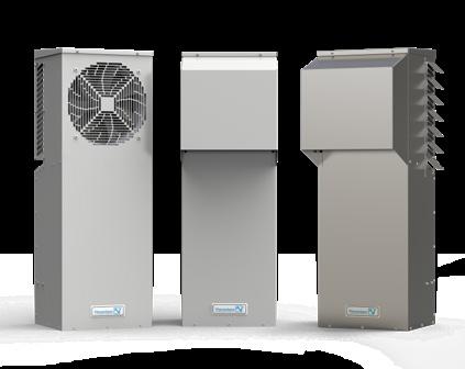
5 2 : UNIT DESCRIPTION 2.1 Description of use Pfannenberg PKS series cooling units are designed to dissipate heat from switch cabinets. Sensitive components in the switch cabinet are protected. 2.2 Scope of delivery The shipment consists of the following contents: PKS cooling unit Cooling unit quick guide Accessory kit: Appropriate seal, fastening material, electrical plug connector, etc. for the specific unit type Special accessories, if applicable 2.3 Order options NOTICE Spare parts from third-party manufacturers can damage the unit Only original parts are subject to the manufacturer s quality control. Only use originally manufacturer parts for safe and reliable operation. For Pfannenberg spare part numbers, see Spare part orders. For Pfannenberg part numbers for accessory orders, see Ordering of accessory parts. WARNING Hazardous due to impermissible use of units Inappropriate use of the units can cause severe accidents. Cooling units must only be used in stationary operation. Pfannenberg cooling units are only approved for stationary operation. As cooling units with protection rating IP 54, the cooling units are essentially dust-protected. Limitation: Dust can still penetrate after continuous exposure. The cooling units are resistant to spray water, but not a constant water jet. Return To Table Of Contents OPERATING MANUAL PKS Page 5


 7")


6 2.4 Functional description Air flow functional principle Airflow Airflow Airflow Airflow Airflow Airflow Airflow Front view Back view Side view Item Number Description Item Number Description 1 Condenser Fan 5 Power Supply Connector 2 Evaporator Fan 6 Voltage Selector 3 Alarm set point control (2TAS) 7 Alarm / Door Contact 4 Unit set point control (1TAS) CAUTION Danger due to the release of very warm air The air outlet can become very warm depending on the ambient temperature. Keep body parts away from the air outlet. For the ambient temperature and air outlet ratio, see Technical data. Page 6 OPERATING MANUAL PKS Return To Table Of Contents

7 2.4.2 Temperature Regulation The thermostats are for the adjustment of refrigeration functions and operating data. Standard controller (SC) operating display Safety concept WARNING Hazards due to modified safety equipment Non-functioning or defective safety equipment can cause severe accidents. Any changes to the unit, particularly the safety equipment, are prohibited. In case of defective safety equipment, shut down the unit and decommission it immediately. Fans and compressors are protected from overloading and overheating. Return To Table Of Contents OPERATING MANUAL PKS Page 7

8 2.5 Type plate WARNING Hazards due to noncompliance with manual Disregarding type plate specifications can result in severe accidents. Always observe the specifications on the type plate when installing and maintaining the units. The figure shows the standard version of type plate A Item Number Designation Item Number Designation 1 Manufacturer logo 11 CE mark 2 Unit type 12 UL mark 3 Part number 13 QR code 4 Serial number 14 Coolant pressure 5 Rated operating voltage 15 Exterior / interior ambient conditions 6 Frequency 16 Cooling capacity 7 Nominal current 17 Coolant 8 Power rating 18 Global Warming Potential 9 Fuse 19 CO2 equivalent value 10 Protection type 18 Page 8 OPERATING MANUAL PKS Return To Table Of Contents
9 2.6 Technical data and spare parts PKS 336X Model PKS 336X (115V, 230V, 400V, 460V) Cooling Data PKS 3361 PKS 3363 PKS 3364 Specific Cooling 20 C rt Q 0 A20(+68 F) / A40(+104 F) Refrigerant Type Refrigerant Amount Adjustable Thermostat Setting 1TAS (factory set) Failure Indication: Enclosure Internal Temp. Ambient Air Temp. Enclosure Internal Temp. Air Volume, External Circulation Air Volume, Internal Circulation 180 w/c 180 w/c 180 w/c 3500 W / BTU/h 3020 W / BTU/h 3020 W / BTU/h R 134a 360 g / 12.7 oz per heat pipe assembly, Unit contains two heat pipe assemblies +35 C / +95 F Set to 15 C above control set point -25 C / -13 F C / +131 F +35 C / +95 F C / +158 F* 1247 m³/h / 734 CFM 957 m³/h / 563 CFM Electrical Data Rated Voltage 115V 230V, 1~ 400V/460V, 1~ 115V 230V, 1~ 400V/460V, 1~ 115V 230V, 1~ 400V/460V, 1~ Main Frequency 60Hz 50/60Hz 50/60Hz 60Hz 50/60Hz 50/60Hz 60Hz 50/60Hz 50/60Hz Operating Range 103V-127V 198V-253V V/ V-127V 198V-253V V/ V-127V 198V-253V V/ Power Consumption (A20/A40) Current Capacity (nom max) Line Cord 353W 245W 245W 353W 245W 245W 353W 245W 245W <3 <2 <1 <3 <2 <1 <3 <2 <1 Connector EMI/RFI Suppression CE EN / EN *115V units, 55 C max internal temp. Return To Table Of Contents OPERATING MANUAL PKS Page 9
10 PKS 336X - ADDITIONAL DATA Mounting Dimensions* PKS 3361 PKS 3363 PKS 3364 Height 889 mm / 35 inch 889 mm / 35 inch 889 mm / 35 inch Width* 305 mm / 12 inch 305 mm / 12 inch 305 mm / 12 inch Depth* 279 mm / 11 inch 279 mm / 11 inch 279 mm / 11 inch Weight (lb) 54 lb (25 kg) & 230V) 64 lb (29 kg) - 400/460V 60 lb (27 kg) & 230V 70 lb (32 kg) - 400/460V 60 lb (27 kg) & 230V 70 lb (32 kg) - 400/460V Installation Attitude vertical or horizontal Unit Construction Sheet steel 304 stainless steel Corrosion Protection galvanized, electrostatically powder coated: RAL 7035, or ANSI61, Baked (200 C / 392 F) 304 stainless steel Protection Classification (Against the enclosure, under correct operating conditions) NEMA Type 12, IP 54 (EN 60529) NEMA Type 3R/4, IP 56 (EN 60529) NEMA Type 4/4x IP 56 (EN 60529) Spare Parts PKS 336X Voltage 115 V 230 V 400 / 460 V Internal Fan External Fan Thermostat Transformer N/A N/A * Note: The 3R/4/4x units have required louvers on the sides which add an additional 3 to the width and a rainhood on the front which adds an additional 4 to the depth. Page 10 OPERATING MANUAL PKS Return To Table Of Contents
11 PKS 330X Model PKS 330X (115V, 230V, 400V, 460V) Cooling Data PKS 3301 PKS 3303 PKS 3304 Specific Cooling 20 C rt Q 0 A20(+68 F) / A40(+104 F) Refrigerant Type Refrigerant Amount Adjustable Thermostat Setting 1TAS (factory set) Failure Indication: Enclosure Internal Temp. Ambient Air Temp. Enclosure Internal Temp. Air Volume, External Circulation Air Volume, Internal Circulation 150 w/c 150 w/c 150 w/c 3240 W / BTU/h 2786 W / 9506 BTU/h 2786 W / 9506 BTU/h R 134a 360 g / 12.7 oz per heat pipe assembly, Unit contains one heat pipe assemblies +35 C / +95 F Set to 15 C above control set point -25 C / -13 F C / +131 F +35 C / +95 F C / +158 F* 1247 m³/h / 734 CFM 957 m³/h / 563 CFM Electrical Data Rated Voltage 115V 230V, 1~ 400V/460V, 1~ 115V 230V, 1~ 400V/460V, 1~ 115V 230V, 1~ 400V/460V, 1~ Main Frequency 60Hz 50/60Hz 50/60Hz 60Hz 50/60Hz 50/60Hz 60Hz 50/60Hz 50/60Hz Operating Range 103V-127V 198V-253V V/ V-127V 198V-253V V/ V-127V 198V-253V V/ Power Consumption (A20/A40) Current Capacity (nom max) Line Cord 353W 245W 245W 353W 245W 245W 353W 245W 245W <3 <2 <1 <3 <2 <1 <3 <2 <1 Connector EMI/RFI Suppression CE EN / EN *115V units, 55 C max internal temp. Return To Table Of Contents OPERATING MANUAL PKS Page 11
12 PKS 330X - ADDITIONAL DATA Mounting Dimensions* PKS 3301 PKS 3303 PKS 3304 Height 889 mm / 35 inch 889 mm / 35 inch 889 mm / 35 inch Width* 305 mm / 12 inch 305 mm / 12 inch 305 mm / 12 inch Depth* 279 mm / 11 inch 279 mm / 11 inch 279 mm / 11 inch Weight (lb) 54 lb (25 kg) & 230V) 64 lb (29 kg) - 400/460V 60 lb (27 kg) & 230V 70 lb (32 kg) - 400/460V 60 lb (27 kg) & 230V 70 lb (32 kg) - 400/460V Installation Attitude vertical or horizontal Unit Construction Sheet steel 304 stainless steel Corrosion Protection galvanized, electrostatically powder coated: RAL 7035, or ANSI61, Baked (200 C / 392 F) 304 stainless steel Protection Classification (Against the enclosure, under correct operating conditions) NEMA Type 12, IP 54 (EN 60529) NEMA Type 3R/4, IP 56 (EN 60529) NEMA Type 4/4x IP 56 (EN 60529) Spare Parts PKS 330X Voltage 115 V 230 V 400 / 460 V Internal Fan External Fan Thermostat Transformer N/A N/A * Note: The 3R/4/4x units have required louvers on the sides which add an additional 3 to the width and a rainhood on the front which adds an additional 4 to the depth. Page 12 OPERATING MANUAL PKS Return To Table Of Contents
13 PKS 320X Model PKS 320X (115V, 230V, 400V, 460V) Cooling Data PKS 3201 PKS 3203 PKS 3204 Specific Cooling 20 C rt Q 0 A20(+68 F) / A40(+104 F) Refrigerant Type Refrigerant Amount Adjustable Thermostat Setting 1TAS (factory set) Failure Indication: Enclosure Internal Temp. Ambient Air Temp. Enclosure Internal Temp. Air Volume, External Circulation Air Volume, Internal Circulation 100 w/c 100 w/c 100 w/c 2120 W / 7234 BTU/h 1972 W / 6729 BTU/h 1972 W / 6729 BTU/h R 134a 360 g / 12.7 oz per heat pipe assembly, Unit contains one heat pipe assemblies +35 C / +95 F Set to 15 C above control set point -25 C / -13 F C / +131 F +35 C / +95 F C / +158 F* 342 m³/h / 201 CFM 308 m³/h / 181 CFM Electrical Data Rated Voltage 115V 230V, 1~ 400V/460V, 1~ 115V 230V, 1~ 400V/460V, 1~ 115V 230V, 1~ 400V/460V, 1~ Main Frequency 60Hz 50/60Hz 50/60Hz 60Hz 50/60Hz 50/60Hz 60Hz 50/60Hz 50/60Hz Operating Range 103V-127V 198V-253V V/ V-127V 198V-253V V/ V-127V 198V-253V V/ Power Consumption (A20/A40) Current Capacity (nom max) Line Cord 75W 75W 75W 75W 75W 75W 75W 75W 75W <1A <1A <1A <1A <1A <1A <1A <1A <1A Connector EMI/RFI Suppression CE EN / EN *115V units, 65 C max internal temp. Return To Table Of Contents OPERATING MANUAL PKS Page 13
14 PKS 320X - ADDITIONAL DATA Mounting Dimensions* PKS 3201 PKS 3203 PKS 3204 Height 889 mm / 35 inch 889 mm / 35 inch 889 mm / 35 inch Width* 305 mm / 12 inch 305 mm / 12 inch 305 mm / 12 inch Depth* 279 mm / 11 inch 279 mm / 11 inch 279 mm / 11 inch Weight (lb) 44 lb (20 kg) & 230V 47 lb (22 kg) - 400/460V 50 lb (23 kg) & 230V 53 lb (24 kg) - 400/460V 50 lb (23 kg) & 230V 53 lb (24 kg) - 400/460V Installation Attitude vertical or horizontal Unit Construction Sheet steel 304 stainless steel Corrosion Protection galvanized, electrostatically powder coated: RAL 7035, or ANSI61, Baked (200 C / 392 F) 304 stainless steel Protection Classification (Against the enclosure, under correct operating conditions) NEMA Type 12, IP 54 (EN 60529) NEMA Type 3R/4, IP 56 (EN 60529) NEMA Type 4/4x IP 56 (EN 60529) Spare Parts PKS 320X Voltage 115 V 230 V 400 / 460 V Internal Fan External Fan Thermostat Transformer N/A N/A * Note: The 3R/4/4x units have required louvers on the sides which add an additional 3 to the width and a rainhood on the front which adds an additional 4 to the depth. Page 14 OPERATING MANUAL PKS Return To Table Of Contents
15 PKS 313X Model PKS 313X (115V, 230V, 400V, 460V) Cooling Data PKS 3131 PKS 3133 PKS 3134 Specific Cooling 20 C rt Q 0 A20(+68 F) / A40(+104 F) Refrigerant Type Refrigerant Amount Adjustable Thermostat Setting 1TAS (factory set) Failure Indication: Enclosure Internal Temp. Ambient Air Temp. Enclosure Internal Temp. Air Volume, External Circulation Air Volume, Internal Circulation 65 w/c 65 w/c 65 w/c 1500 W / 5118 BTU/h 1410 W / 4811 BTU/h 1410 W / 4811 BTU/h R 134a 360 g / 12.7 oz per heat pipe assembly, Unit contains one heat pipe assemblies +35 C / +95 F Set to 15 C above control set point -25 C / -13 F C / +131 F +35 C / +95 F C / +158 F* 342 m³/h / 201 CFM 308 m³/h / 181 CFM Electrical Data Rated Voltage 115V 230V, 1~ 400V/460V, 1~ 115V 230V, 1~ 400V/460V, 1~ 115V 230V, 1~ 400V/460V, 1~ Main Frequency 60Hz 50/60Hz 50/60Hz 60Hz 50/60Hz 50/60Hz 60Hz 50/60Hz 50/60Hz Operating Range 103V-127V 198V-253V V/ V-127V 198V-253V V/ V-127V 198V-253V V/ Power Consumption (A20/A40) Current Capacity (nom max) Line Cord 75W 75W 75W 75W 75W 75W 75W 75W 75W <1A <1A <1A <1A <1A <1A <1A <1A <1A Connector EMI/RFI Suppression CE EN / EN *115V units, 65 C max internal temp. Return To Table Of Contents OPERATING MANUAL PKS Page 15
16 PKS 313X - ADDITIONAL DATA Mounting Dimensions* PKS 3131 PKS 3133 PKS 3134 Height 889 mm / 35 inch 889 mm / 35 inch 889 mm / 35 inch Width* 305 mm / 12 inch 305 mm / 12 inch 305 mm / 12 inch Depth* 279 mm / 11 inch 279 mm / 11 inch 279 mm / 11 inch Weight (lb) 44 lb (20 kg) & 230V 47 lb (22 kg) - 400/460V 50 lb (23 kg) & 230V 53 lb (24 kg) - 400/460V 50 lb (23 kg) & 230V 53 lb (24 kg) - 400/460V Installation Attitude vertical or horizontal Unit Construction Sheet steel 304 stainless steel Corrosion Protection galvanized, electrostatically powder coated: RAL 7035, or ANSI61, Baked (200 C / 392 F) 304 stainless steel Protection Classification (Against the enclosure, under correct operating conditions) NEMA Type 12, IP 54 (EN 60529) NEMA Type 3R/4, IP 56 (EN 60529) NEMA Type 4/4x IP 56 (EN 60529) Spare Parts PKS 313X Voltage 115 V 230 V 400 / 460 V Internal Fan External Fan Thermostat Transformer N/A N/A * Note: The 3R/4/4x units have required louvers on the sides which add an additional 3 to the width and a rainhood on the front which adds an additional 4 to the depth. Page 16 OPERATING MANUAL PKS Return To Table Of Contents
17 3 : ASSEMBLY AND INITIAL COMMISSIONING 3.1 Transport WARNING Hazards due to uncontrolled movements Improper securing of the unit can result in severe accidents. Loading must only be carried out by trained, qualified personnel. Lash the unit correctly for transport on a truck or trailer. Only use lashing straps with an adequate rated strength. Use slip-resistant materials for securing, e.g. anti-slip mats. When loading by crane, do not walk or stand under the raised units. NOTICE Danger of material damage during transport and setting down of the units. Improper device securing or uncontrolled movements can cause damage. Exercise maximum caution during movement and transport of the units. Always transport the cooling units using the packaging provided by the factory. Transporting cooling units REQUIREMENTS: Cooling units must be in the packaging provided by the factory. REQUIRED TOOLS AND MATERIAL: Lashing straps, loading crane, if applicable PROCEDURE: Always raise cooling units by the housing. Always raise cooling units slowly and evenly and set down safely. Secure correctly for transport with lashing straps. The cooling unit was transported and loaded correctly. 3.2 Storage Do not expose the cooling unit to temperatures above +70 C during storage*. * The warranty will no longer apply if these instructions are not observed. Return To Table Of Contents OPERATING MANUAL PKS Page 17
18 3.3 Unpacking WARNING Hazard of accidents due to the heavy weight of the units Uncontrolled movements of the units during assembly can cause accidents. Use suitable lifting equipment and secure units to prevent accidents. Also secure assembled components. CAUTION Hazard of injury due to sharp edges For manufacturing reasons, the metal edges of the unit may have burrs. Wear gloves during service and assembly work. NOTICE Perform a visual inspection for transport damage when unpacking the cooling units. Take note of any loose parts, dents, scratches, visible loss of oil etc. Inspect and secure the packaging material for any loose functional parts before disposal. Report any damages to the freight carrier immediately. Observe the Terms for Cases of Damage. Precise information about defects, including possible photos must be provided for the handling of warranty claims. Always specify the type designation and serial number. 3.4 Assembly DANGER Life-threatening hazard due to electric shock Live units and exposed connection cables can generate an electric shock and cause severe accidents. Work on electrical connections must be carried out exclusively by trained, qualified electricians. Before assembly, de-energize all supply lines to the separate fuse or a main switch, disconnect the system and secure to prevent re-connection. Test to ensure the absence of voltage on the unit. CAUTION Hazard of crushing during assembly of the unit There is a hazard of crushing between the switch cabinet and frame of the unit during assembly. Keep body parts out of the space between the frame and unit cut-out. Work carefully and wear gloves. NOTICE Switch cabinet installation hazard due to assembly chips When making the cooling unit cut-outs, assembly chips can fall into the switch cabinet. When assembling the switch cabinet, protect against contaminants and use protective covers General assembly requirements Select an assembly location for the switch cabinet which will guarantee adequate ventilation of the cooling unit. A minimum clearance of 200 mm between units and the nearest wall must be observed. Installed components in the switch cabinet must not impede air circulation. Protect the installation location from heavy contamination with covers. CAUTION The following general requirements must be followed for safe and reliable operation of the cooling units: Secure the switch cabinet against tipping. Ensure that provided hinges can support the additional weight of the cooling unit. Page 18 OPERATING MANUAL PKS Return To Table Of Contents
19 3.4.2 PKS cooling unit assembly (side attachment) 769.3mm [30.29 ] (300mm [11.81 ]) 549.3mm [21.63 ] 451mm [17.76 ] 434.5mm [17.11 ] 888mm [34.96 ] Switch cabinet exterior view. Cut-outs for PKS cooling unit mm [11.82 ] 150.3mm [5.92 ] 18.5mm [0.73 ] 0 14X Ø8mm [0.31 ] 8mm[0.31 ] 134mm[5.28 ] 260mm[10.24 ] 268mm[10.55 ] Item Number Designation Item Number Designation 1 Holes 2 Device size 3 Cut-outs Make cut-outs for the PKS cooling unit REQUIREMENTS: All general requirements have been fulfilled; see General assembly requirements The unit is de-energized REQUIRED TOOLS AND MATERIAL Saw Use a switch cabinet cutter, if applicable Protective covers PROCEDURE Use a protective cover to protect the switch cabinet from chips. Provide the switch cabinet with cut-outs (3) and holes (1). For the prescribed dimensions, refer to the figure exterior view of the switch cabinet. Deburr the cut edges. Remove chips and assembly waste from the switch cabinet. Cut-outs and holes have been made. Return To Table Of Contents OPERATING MANUAL PKS Page 19

20 Install seal on the PKS cooling unit (side attachment) DANGER Hazard of accidents due to incorrectly installed seals Leaky seals can allow moisture to penetrate and cause short-circuits. Install the seal so that it provides a tight seal to the switch cabinet. Always inspect seals during cleaning and maintenance. Item Number Designation Item Number Designation 1 Unit seals 2 Cabinet mounting holes 3 Cabinet cut-out 4 Enclosure Install seals and assembly REQUIREMENTS: Cut-outs for the PKS cooling unit have been made; see figure PKS cooling unit assembly. The cooling unit is de-energized. REQUIRED TOOLS AND MATERIAL Installation tool Accessory kit: Threaded bolts, screws, nuts, washers PROCEDURE Attach seals (1) on the PKS unit (2). Fit the seals with the slotted holes over unit mounting holes. Screw in the two supplied threaded bolts (accessory kit) in the upper fastening points of the PKS cooling unit. Suspend the cooling unit on the switch cabinet with the threaded bolts installed from outside. Tighten the screws on the PKS cooling unit on the switch cabinet interior. Use the supplied screws, nuts and washers (accessory kit) to fasten the unit. Firmly tighten the screw fasteners so that the seal is pressed together. The PKS cooling unit is attached to the switch cabinet and ready for electrical connection; see Electrical connection. Page 20 OPERATING MANUAL PKS Return To Table Of Contents
21 3.5 Electrical connection Standard controller (SC) electrical circuit diagram DANGER Life-threatening hazard due to electric shock Live units and exposed connection cables can generate an electric shock hazard and cause severe accidents. Work on electrical connections must be carried out exclusively by trained, qualified electricians. Ensure that the unit is voltage-free before routing all electrical connections. 1TAS WNL WNL C 1 2 L 3MTR N L N 2MTR Z WNN 400/460V OPTION WNL BRN BLU WXT T1 115/230V OPTION RED ORG blu 2 PE blk gn/yell brn C11 4 X57 WNN WNN 65W and 100W UNITS X60 ORG 4 X58 RED 2TAS C 1 2 X PE 3 X PE 3 4 Max. 2.5mm / AWG /230V 50/60 Hz 1 Phase 400/460V 50/60 Hz 1 Phase Item Number Designation Item Number Designation Item Number Designation 2MTR Condenser fan 3MTR Evaporator fan 1TAS Thermostat 2TAS High Temperature Alarm T1 Transformer X50 Connection mains X54 Connection door contact + failure indication 3-4 Door Contact : If door contact is used, remove bridge between wire X55 Transformer Switch Return To Table Of Contents OPERATING MANUAL PKS Page 21
22 3.5.2 Door contact switch WARNING Hazard due to connection of external voltage at the input of the door contact External voltage can cause severe accidents. Connection of external voltage to the input for the door cabinet is prohibited. Installation of a door contact switch increases safety and prevents increased accumulation of condensate. If a door contact switch has not been connected, the connection contact (S1) must be jumped. Door contact switch installation REQUIREMENTS: The cooling unit is de-energized. PROCEDURE: The door contact switch is connected to the S1 connection; see Electrical connection or the electrical circuit diagram in the housing cover. The door contact is supplied with high voltage, from the cooling unit. The door contact switch is connected. The motors switch off when the switch cabinet is opened Main supply connection WARNING Potential hazard due to incorrect cables An incorrect cable cross-section will cause the cable to overheat. Scorched insulation can cause fires. The cable cross-section (4) matches the output required for the power consumption and is 1 2.5mm² or AWG 18 to AWG 14. DANGER Electric arcing can cause electric shock and burns. When disconnecting and connecting the plug connector for mains connection under load or voltage, electric arcing, dangerous voltage and electric shock can occur. The plug connector for mains connection must never be plugged in or disconnected under load/voltage. Work on plug connectors must only be carried out with adequate lighting. Always disconnect power to unit. The following general requirements must be ensured for safe and reliable operation of the cooling units: Upstream installation of a supply-side temperature regulator is prohibited. Connect the upstream fuse specified on the type plate as wiring protection; see Type plate. Ensure that the type plate specifications for rated values match the present values for mains voltage and mains frequency; see Type plate. Always connect the cooling unit to the mains by means of a separating device (switch/contactor). Page 22 OPERATING MANUAL PKS Return To Table Of Contents

23 Cooling unit electrical connection DANGER Life-threatening hazard due to electric shock Circuit breaker systems that are not connected or attached incorrectly can generate hazardous voltages and electric shock and cause severe accidents. Work on electrical connections must be carried out exclusively by trained, qualified electricians. Circuit breakers systems must be provided in accordance with DIN EN , chapter 8.2. Each element of electrical equipment must be connected to the circuit breaker system. Never interrupt the circuit breaker system if electrical equipment is attached to covers, doors or cover panels. If parts are removed, e.g. for maintenance work, ensure that the circuit breaker system is not interrupted for the remaining parts. Part Description: Connection Instruction Refer to Connection Diagram: 115V 230V 230V 460V 460V 1 L L L L1 L1 2 N N L L2 L L3 PE Screw Connections Connector Strain Relief Ø / Ø Ø Conductor PE N,L PE N,L Dismantling Length y (mm) Dismantling Length y (splitter connector) Insulation Strip Length x (mm) 8 (conductor cross section 1, mm 2 ) Dismantling and Insulation Strip Lengths (mm) Dismantling and Insulation Strip Lengths (mm) Return To Table Of Contents OPERATING MANUAL PKS Page 23

. The connectors are not suitable for current interrupting. Never connect or disconnect under load!")
24 Opening the Connector Wire Connection Screw connection: Drive PZ1, Tightening torque typ. 0.5 Nm 1 2 Detail Closing Plugging and Locking 2 Clicks into place Clicks into place Clicks into place Screw connection: Tightening torque typ. 4+1 Nm 1 CAUTION To maintain the IP-rating type of enclosure, protective caps (accessory) must be mounted on all unoccupied connectors! Further the connectors must not be exposed to bending forces (e.g. do not attach loads to the cable, no free-dangling cable windings etc.). The connectors are not suitable for current interrupting. Never connect or disconnect under load! Requirement All general requirements for safe and reliable operation are assured; see Main supply connection. The cooling unit is de-energized. Procedure Connect the cable (4) with the connecting plug (1)/(accessory kit) as specified in the electrical circuit diagram; see Electrical connection. For electrical connection, insert the screwdriver (3) into the cage terminal (2) and connect the cables (4) to the cooling unit with the connecting plug (1). Insert the screwdriver firmly into the cage terminal (2). Never twist the screwdriver; otherwise the cage terminal (2) will be damaged. Before switching on, ensure that the mains voltage matches the upstream fuse; see Electrical connection. The cooling unit is connected electrically. Page 24 OPERATING MANUAL PKS Return To Table Of Contents
25 4 : OPERATION 4.1 General functions NOTICE Danger of damage to the cooling unit Operation without the unit cover prevents the adequate supply of air to the condenser and limits the intended heating function. Only operate the cooling unit with the unit cover installed. Once assembly and installation work is completed, switch on the power supply to the cooling unit. After the supply voltage has been connected and the door is closed, the units run continuously. The cooling unit (2) is equipped with an electronic control unit. A temperature sensor (4) detects the temperature of the air sucked in from the interior of the switch cabinet (3). If the upper or lower limit temperature is exceeded or undercut, a fault indication is triggered (6). The ambient conditions and switch cabinet interior temperatures must correspond to the prescribed technical data; see Technical data. The ambient temperature must be less than 55 C. 4.2 Operation of the cooling unit After connection of the mains voltage, the device switches to operating mode. If cooling mode as needed; this will take place depending on whether a temperature switching threshold (TSet) is reached or undercut. Cooling mode switches off when the temperature switching threshold (TSet) is undercut. The evaporator fan (internal) and condenser fan (external) switch off when the door is opened. Operating conditions The mains voltage must lie within the specified range; see Electrical data. A deviation of ± 10 % is permissible. The ambient temperature must be below 55 C. For further options, see Technical data. The cooling unit must only be used in such a manner as to ensure that the specified cooling capacity is able to meet actual demands. Only the specified coolant may be used. Return To Table Of Contents OPERATING MANUAL PKS Page 25
26 5 : SERVICE AND MAINTENANCE 5.1 General Cleaning DANGER Life-threatening hazard due to electric shock Live units and exposed connection cables can generate an electric shock and cause severe accidents. Work on electrical connections must be carried out exclusively by trained, qualified electricians. Before working on the unit, de-energize all supply lines to the separate fuse or a main switch, disconnect the system and secure to prevent re-connection. Test to ensure the absence of voltage on the unit. WARNING Hazards of accidents due to component damage during cleaning Cleaning of cooling units with water jet, steam jet, high-pressure washer or sharp objects can damage the electrical and electronic assemblies. Malfunctions can cause accidents. Do not clean with a water jet, pressure washer or flammable cleaning agents. Protect electrical components from the penetration of moisture. Do not use pointed or sharp-edged objects to clean the fins. They must not be pinched or damaged. CAUTION Hazards of crushing during removal of the unit cover Hands and other body parts can be crushed during removal and re-installation of the unit cover. Keep body parts out of the space between the frame, springs and unit cut-out. Work carefully and wear gloves. The frequency of cleaning intervals depends on the operating conditions in the individual case. The following cleaning work must take place regularly for safe and reliable operation of the cooling units: Remove dust or environmental residue from the heat exchangers. Check the condensate drain regularly. Page 26 OPERATING MANUAL PKS Return To Table Of Contents
27 5.2 Maintenance DANGER Life-threatening hazard due to electric shock Live units and exposed connection cables can generate an electric shock and cause severe accidents. Opening, troubleshooting and replacement of components on the unit must only be carried out by qualified personnel. Always ensure that the unit is de-energized before working on the unit. WARNING Hazard due to improper maintenance work Damage of components and faulty replacement of components can cause accidents. Always switch off the disconnector/contactor before beginning maintenance work. Wait For unloading phase of 5 minutes for the electric components. Open only afterwards device. Ensure that the fans are in idle position and are no longer rotating. After replacement of defective parts or components, inspect the unit for correct and safe operation. After all maintenance or replacement of spare parts, check to ensure the full capability of the condensate drain. WARNING Spare parts from third-party manufacturers can damage the unit and cause accidents. Only original parts are subject to the manufacturer s quality control. Only use specially agreed manufacturer parts for safe and reliable operation. NOTICE Danger of unit damage due to incorrectly performed maintenance Disregard of the recommended maintenance work reduces the cooling capacity of the cooling unit and could result in reduced machine availability. Maintenance work must be carried out regularly, as specified in the maintenance checklist. Warranty claims are only valid for units that have been maintained according to specifications. Pfannenberg recommendation to the operator for maintenance work: Carry out maintenance work regularly, every 12 months, according to the maintenance checklist; see Maintenance checklist template. Shorter maintenance intervals are required for cooling units that cool in oil- and dust-laden ambient air. A reduced guideline value of two to six months between maintenance intervals applies. Return To Table Of Contents OPERATING MANUAL PKS Page 27
28 5.3 Maintenance checklist template Cooling Unit Maintenance Checklist Maintenance Interval: Conduct maintenance every twelve months. Conduct maintenance every two to six months in oil and dust-laden environmental air. Type: Serial number: Date of maintenance: Technician: Unit range designation/ Required maintenance tasks 1 Aggregate before maintenance 1.1 General visual inspection of the aggregate 1.2 Inspection for corrosion damage 2 Condenser / heat exchanger 2.1 Inspection for general corrosion damage 3 Condenser fan (external) 3.1 Inspect mount for loose parts 3.2 Inspect the electrical connection for damage 3.3 Check motor bearings for noises 3.4 Check the drive for signs of overheating 4 Condenser fan (internal) 4.1 Inspect mount for loose parts 4.2 Inspect the electrical connection for damage 4.3 Check motor bearings for noises 4.4 Check the drive for signs of overheating Visual inspection * Maintenance intervals are more frequent, depending on the degree of contamination. To Do Result Page 28 OPERATING MANUAL PKS Return To Table Of Contents
29 5.4 Decommissioning WARNING Hazard of injury due to materials and substances Improper work on the unit can be damaging to health. Always ensure that the unit is de-energized before working on the unit. The unit must only be disposed of by qualified personnel and in accordance with applicable environmental regulations. If the cooling unit is no longer needed for a longer period, it must be disconnected from the voltage supply. Ensure that improper start-up by third parties is not possible. Final Decommissioning CAUTION Hazard of crushing during the decommissioning of units Hands and other body parts can be crushed during removal of units. Keep body parts out of the space between the frame, springs and unit cut-out. If cooling units are to be definitively decommissioned or disposed of, the following must be observed: Applicable statutory regulations of the user country and environmental protection regulations must be observed. Refrigerant must be professionally extracted from the refrigerant system. Avoid refrigerant emissions. The cooling unit must only be disposed of by authorized, qualified personnel. Waste equipment must also be disposed of correctly by Pfannenberg. Freight charges for delivery to one of our manufacturing facilities must be pre-paid. Return To Table Of Contents OPERATING MANUAL PKS Page 29
30 6 : TROUBLESHOOTING Fault Possible causes Corrective measures Unit does not cool; evaporator fan (internal) running Unit does not cool sufficiently Temperature setting too high Operating limits exceeded Too little coolant Heat exchanger dirty Evaporator fan (internal) defective Condenser fan (external) defective Check the temperature setting Check the ambient temperature and internal load Call in authorized qualified personnel; check the unit for leakage Clean the heat exchanger Call in authorized, qualified personnel; replace fan Check the installation and the path of air circulating in the switch cabinet Disruption in the air circulation inside the cabinet Check the supply and outlet flow of air of the cooling unit to the inlet and outlet opening of the switch cabinet Page 30 OPERATING MANUAL PKS Return To Table Of Contents
31 7 : ACCESSORIES Item Number Designation Kit louveres - light grey Kit louveres - stainless steel Kit filter Kit accessory pack Item Number Designation Note: Always specify the Pfannenberg part numbers when ordering spare parts and accessory parts. 8 : TERMS OF WARRANTY The warranty does not apply or is voided in the following cases: Improper use of the unit. Failure to observe operating conditions or disregard of the operating manual. Lack of regular maintenance on the cooling units. Damage due to disregard of maintenance recommendations. Damage to cooling units due to soiled or clogged filters. Damage due to unauthorized opening of the refrigerant circuit. Modifications carried out on the unit or a change to the serial number. In the event of damage during transport or other accidents. Replacement of parts by unauthorized personnel. Only original Pfannenberg parts are permitted for use. Violations void the warranty. For recognition of warranty claims and return of the unit, observe the following: Provide an exact description of the defect and the SRO (RMA) numbers specified by Pfannenberg with the cooling unit. Include a reference document (delivery note or invoice copy). Forward the cooling unit to us, complete with all accessories, in the original box or in comparable packaging with freight and transport insurance pre-paid. Observe transport instructions; see Transport. Pfannenberg Incorporated 68 Ward Road, Lancaster, New York Phone: Fax: sales@pfannenbergusa.com All information contained was thoroughly checked in However, we make no guarantee as to the completeness and correctness of the specifications. Return To Table Of Contents Org 07/17/ Pfannenberg Incorporated OPERATING MANUAL PKS Page 31
Technical Manual. Operation and installation cooling units PKS 3000 SERIES 115V / 230V / 460V. Version 1.0, March 2018
 Technical Manual Operation and installation cooling units PKS 3000 SERIES 115V / 230V / 460V Version 1.0, March 2018 Preface The skills and information provided in the ORIGINAL OPERATING MANUAL are required
OK, OKA, OKAF; ELD; ELDM; ELH; OKC; SC; SCA; SCAF; OK-LN; OKA-LN; OKAF-LN.
 INSTALLATION, OPERATION & SERVICE MANUAL FOR COOLER TYPES OK, OKA, OKAF; ELD; ELDM; ELH; OKC; SC; SCA; SCAF; OK-LN; OKA-LN; OKAF-LN. 1. Introduction This manual is a guide for the installation, maintenance
KNHE48 SERIES WATER-TO-AIR HEAT EXCHANGER
 Keep This Manual With Heat Exchanger Find additional information on this model at kooltronic.com or use the Technical Documents QR code below. Technical Documents KNHE48 SERIES WATER-TO-AIR HEAT EXCHANGER
! The Caution Symbol (exclamation point) alerts you to a "CAUTION", a safety or
 alerts you to a CAUTION, a safety or") I&M NUMBER: 316-42-10-1 Page: 1 Pre Installation Check to make sure that heater received is the same as that ordered. Elements may come in contact with each other during shipment. Minor adjustments to
I&M NUMBER: 316-42-10-1 Page: 1 Pre Installation Check to make sure that heater received is the same as that ordered. Elements may come in contact with each other during shipment. Minor adjustments to
Operating instructions
 ebm-papst Mulfingen GmbH & Co. KG Bachmühle D-74673 Mulfingen Phone +49 (0) 793-0 Fax +49 (0) 793-0 info@de.ebmpapst.com www.ebmpapst.com CONTENTS. SAFETY REGULATIONS AND NOTES. Levels of hazard warnings.
KNHE30 SERIES WATER-TO-AIR HEAT EXCHANGER
 Keep This Manual With Heat Exchanger Find additional information on this model at kooltronic.com or use the Technical Documents QR code below. Technical Documents KNHE30 SERIES WATER-TO-AIR HEAT EXCHANGER
KPHE24 SERIES WATER-TO-AIR HEAT EXCHANGER
 Keep This Manual With Heat Exchanger Find additional information on this model at kooltronic.com or use the Technical Documents QR code below. Technical Documents KPHE24 SERIES WATER-TO-AIR HEAT EXCHANGER
WATLOW IND. FIREBAR Flange Heater Installation & Maintenance Manual I&M NUMBER: Page: 1 Date: 6/11/2008 Rev: 2.00
 I&M NUMBER: 316-42-2-1 Page: 1 Pre Installation Check to make sure that heater received is the same as that ordered. Elements may come in contact with each other during shipment. Minor adjustments to elements
User Manual GV25 GV35 GV702. Company information: Original instructions GV12066 (1)
") User Manual Original instructions GV25 GV35 GV702 Company information: www.vipercleaning.eu info-eu@vipercleaning.com GV12066 (1) 2012-04-10 USER MANUAL ENGLISH TABLE OF CONTENTS Introduction... 4 Manual
User Manual Original instructions GV25 GV35 GV702 Company information: www.vipercleaning.eu info-eu@vipercleaning.com GV12066 (1) 2012-04-10 USER MANUAL ENGLISH TABLE OF CONTENTS Introduction... 4 Manual
KPHE32 SERIES WATER-TO-AIR HEAT EXCHANGER
 Keep This Manual With Heat Exchanger Find additional information on this model at kooltronic.com or use the Technical Documents QR code below. Technical Documents KPHE32 SERIES WATER-TO-AIR HEAT EXCHANGER
WATLOW IND. WATROD Flange Heater Installation & Maintenance Manual I&M NUMBER: Page: 1 Date:6/11/2008 Rev: 2.00
 I&M NUMBER: 316-42-8-1 Page: 1 _ Pre Installation Check to make sure that heater received is the same as that ordered. Elements may come in contact with each other during shipment. Minor adjustments to
EN Z Subject to change due to technical improvements! Operating instructions
 SOLARTHERMIE - SOLAR THERMAL - SOLAR TÉRMICO - SOLAIRE THERMIQUE Operating instructions Temperature differential controller 3 inputs, 1 output These operating instructions are part of the product. Read
WATLOW IND. WATROD Circulation Heater Installation & Maintenance Manual I&M NUMBER: Page: 1 Date: 6/11/2008 Rev: 2.00
 I&M NUMBER: 316-42-5-1 Page: 1 Pre Installation Check to make sure that heater received is the same as that ordered. Watlow heaters are built to comply with UL and CSA dielectric requirements, it may be
WATLOW ELECTRIC MFG CO. FIREBAR Screw Plug Installation & Maintenance Manual I&M NUMBER: Page: 1 Date: 11/25/2013 Rev: 4.
 I&M NUMBER: 316-42-3-1 Page: 1 Pre Installation Check to make sure that heater received is the same as that ordered. Elements may come in contact with each other during shipment. Minor adjustments to elements
InstructIon Manual KrEs EQuIPMEnt stands
 Instruction Manual Instruction Manual SELF-CONTAINED AND REMOTE Kairak KRES model refrigerated equipment stand units are available in many lengths from 36 to 120 inches long. These units are available
Friwa Compact. Operating instructions EN
 Operating instructions EN Version 1.1 / Edition 09/2013 Contents 1 Key background information... 3 1.1 Limitation of liability... 3 1.2 Responsibilities of the operator... 3 1.3 Documentation... 3 1.3.1
HI Industrial Utility Heater HI Soleus Air International
 HI1-50-03 Industrial Utility Heater HI1-50-03 2010 Soleus Air International Thank you for choosing a Soleus Air Utility Heater. This owner s manual will provide you with valuable information necessary
Panel Fan Series Operators Manual (Galvanized and Polymer)
") Panel Fan Series Operators Manual (Galvanized and Polymer) Galvanized Panel Fan with Three Wing Blade IMPORTANT: READ AND SAVE THESE INSTRUCTIONS Read all instructions carefully before attempting to assemble,
Panel Fan Series Operators Manual (Galvanized and Polymer) Galvanized Panel Fan with Three Wing Blade IMPORTANT: READ AND SAVE THESE INSTRUCTIONS Read all instructions carefully before attempting to assemble,
Installation GUIDE VDWU524SS VDWU524WSSS FDWU524WS FDWU524 VDWU324SS FDWU324
 Installation GUIDE VDWU524SS VDWU524WSSS FDWU524WS FDWU524 VDWU324SS FDWU324 To prevent accidents, which could cause serious injury or death, as well as machine damage read these instructions before installation
Installation/Instruction Manual
 1510876HC8902 Pressurized ventilators (for device cooling) Model Blade diameter (cm) Indoor or outdoor EF-20UYS-UL EF-25UAS-UL EF-30UBS-UL 20 25 30 Indoor Installation/Instruction Manual For customers
ADVANTAGE SERIES KXRP28 AIR-TO-AIR HEAT EXCHANGER
 Keep This Manual With Heat Exchanger Find additional information on this model at kooltronic.com or use the Technical Documents QR code below. Technical Documents ADVANTAGE SERIES KXRP28 AIR-TO-AIR HEAT
Installation Instructions
 50ES---A, 50EZ---A, 50VL---A, 50VG---A, 50VR---A, 50VT---A, 604D--- ---A, 607C--- ---A, 607E,--- ---A, 704D--- ---A, 707C--- ---A, 707E--- ---A PA3G --- --- A, PH3G --- --- A SMALL PACKAGED PRODUCTS Electric
FLCH4R Garage and Utility Electric Heater
 FLCH4R Garage and Utility Electric Heater Installation, Operation & Maintenance Instructions Model No. Volts Amps Watts BTU/HR Phase High Low High Low High Low Min Fuse Size* FLCH4R 208 17.3 8.66 3600
Installation Instructions
 EHNA Electric Heaters 5-20kW For 60 Hz Small Packaged Products MODELS: PAD3, PHD3, PAD4, PHD4, PAD5, PHD5, WPA3, WPH3 Installation Instructions NOTE: Read the entire instruction manual before starting
Installation Instructions T 9822 Gas Dryer. en - US, CA. To prevent accidents
 Installation Instructions T 9822 Gas Dryer To prevent accidents en - US, CA and appliance damage read these instructions before installation or use. M.-Nr. 07 431 110 2 WARNING For your safety the information
KNHX32 SERIES NEMA 4/4X AIR-TO-AIR HEAT EXCHANGERS
 Keep This Manual With Heat Exchanger Find additional information on this model at kooltronic.com or use the Technical Documents QR code below. Technical Documents KNHX2 SERIES NEMA /X AIR-TO-AIR HEAT EXCHANGERS
Operating instructions
 SOLARTHERMIE - SOLAR THERMAL - SOLAR TÉRMICO - SOLAIRE THERMIQUE Operating instructions Temperature Differential Controller inputs, 1 output These operating instructions are part of the product. US Read
Installer manual AG-AA10. Air/air heat pump IHB GB AG-AA10-30 AG-AA10-40/50
 -30 Installer manual Air/air heat pump -40/50 IHB GB 1516-1 331554 Table of Contents 1 Important information 2 5 Installation 7 Safety information 2 Model combinations 7 Read before starting the installation
DISHWASHER. Models DW2432 and DW2432SS. Installation Manual. Write Serial Number (on inner door of unit) here:
 here:") DISHWASHER Models DW2432 and DW2432SS Installation Manual Write Serial Number (on inner door of unit) here: Felix Storch, Inc. Summit Appliance Division 770 Garrison Avenue Bronx, New York 10474 www.summitappliance.com
DISHWASHER Models DW2432 and DW2432SS Installation Manual Write Serial Number (on inner door of unit) here: Felix Storch, Inc. Summit Appliance Division 770 Garrison Avenue Bronx, New York 10474 www.summitappliance.com
HKF 8180 Operating instructions
 Operating instructions EN Version 1.0en /Edition 05/2013 Contents 1 Important basic information... 3 1.1 Limitation of liability... 3 1.2 Operator's responsibilities... 3 1.3 Documentation... 3 1.3.1 Content
TABLE OF CONTENTS. NOTE: Read the entire instruction manual before starting the installation. TROUBLESHOOTING... 13
 R 410A Duct Free Split System Air Conditioner and Heat Pump Product Family: DFS4(A/H) System, DFC4(A/H)3 Outdoor, DFF4(A/H)H Indoor NOTE: Read the entire instruction manual before starting the installation.
Quality Enclosures. Service Excellence.
 Cooling Products General Information...5 General Selection Considerations...5 Sizing an Air Conditioner...6 General Specifications for Air Conditioners...7 Side Mounting DTS Series Air Conditioners 1200
AA-480-XX OUTDOOR THERMOELECTRIC COOLER ASSEMBLY USER S MANUAL
 AA-480-XX OUTDOOR THERMOELECTRIC COOLER ASSEMBLY USER S MANUAL Table of Contents Introduction 3 Incoming Inspection 3 General Safety & Warnings 3 Technical Specifications 4 Installation and Operation Instructions
GARAGE HEATER WITH REMOTE INSTRUCTION MANUAL MODEL: HA24-100E HA24-150E. Figure 1
 GARAGE HEATER WITH REMOTE INSTRUCTION MANUAL MODEL: HA24-100E HA24-150E Figure 1 PET OWNERS WARNING: Health warning for some small pets, including birds, as they are extremely sensitive to the fumes produced
K Operating Instructions. Before first use of the unit read these operating instructions and act in accordance with them.
 K 1.100 Operating Instructions Before first use of the unit read these operating instructions and act in accordance with them. www.kaercher.com/register-and-win 59651430 (10/13) Contents General information..............
Steam Trap BK 45 BK 45-U BK 45-LT BK 46
 Steam Trap BK 45 BK 45-U BK 45-LT BK 46 Original Installation Instructions 810437-08 Contents Foreword... 3 Availability... 3 Formatting features in the document... 3 Safety... 3 Use for the intended purpose...
Thermal Management and Signaling Technology
 Thermal Management and Signaling Technology for Food & Beverage Applications ELECTRO-TECHNOLOGY FOR INDUSTRY A Full Range of Thermal Management Solutions for Control and Process Equipment With products
Installation Instructions. Mira LED Light System
 Installation Instructions Mira LED Light System w w w. a m i c o. c o m Contents Symbols Used in This Manual 4 Safety Instructions 5 Variants 7 Scope Of Delivery 8 Installing Mira LED Ceiling Mounted Installing
OPERATIONS AND MAINTENANCE MANUAL FOR THE 8-TON TURF CART ENVIRONMENTAL CONTROL UNIT (ECU) PART NUMBER
 PART NUMBER") OPERATIONS AND MAINTENANCE MANUAL FOR THE 8-TON TURF CART ENVIRONMENTAL CONTROL UNIT (ECU) PART NUMBER 2001927 Prepared by: 860 Douglas Way PO Box 530 Natural Bridge Station, VA 24579 1 1.0 SCOPE: This
OPERATIONS AND MAINTENANCE MANUAL FOR THE 8-TON TURF CART ENVIRONMENTAL CONTROL UNIT (ECU) PART NUMBER 2001927 Prepared by: 860 Douglas Way PO Box 530 Natural Bridge Station, VA 24579 1 1.0 SCOPE: This
Installation manual plugs and connectors QUICK-CONNECT (63 A)
") EN Installation manual plugs and connectors QUICK-CONNECT (63 A) 60003217 Issue 04.2016 2016-04-01 Table of contents 1 About this manual 3 1.1 Structure of the warnings 3 1.2 Symbols used 4 1.3 Signal
EN Installation manual plugs and connectors QUICK-CONNECT (63 A) 60003217 Issue 04.2016 2016-04-01 Table of contents 1 About this manual 3 1.1 Structure of the warnings 3 1.2 Symbols used 4 1.3 Signal
XT Series Thermostats
 ISO 9001 Explosion-Proof & Moisture Resistant XT Series Thermostats Installation, Operation, & Maintenance Instructions XTWA Thermostat XTWL Thermostat XTB Thermostat Part No.MI133.Rev.2.00 Date of Issue:
Installation and Operation Manual CLEARVIEW DAY COVER CAUTION: To view a video scan the QR code above
 Installation and Operation Manual CLEARVIEW DAY COVER To view a video scan the QR code above CAUTION: Please read this manual completely before attempting to install, operate or service this equipment
VARIABLE SPEED GRINDER OWNER S MANUAL R MANUAL VERSION SERIAL #
 R3.5 VARIABLE SPEED GRINDER SERIAL # MANUAL VERSION CONFORMS TO UL STD 763, NSF/ANSI STD 8 CERTIFIED TO CSA STD C22.2 #95 CONFORMS TO CE, IEC TESTED 2. Introduction WARNING: To limit risk of personal injury
Operating Instruction
 Version 0 21/02/2017 Operating Instruction Hot air dryer english Item No. 108 3106 Elma Schmidbauer GmbH Gottlieb-Daimler-Str. 17 D-78224 Singen Tel. +49 7731 882-0 Fax +49 7731 882-266 info@elma-ultrasonic.com
Dryer. User manual DV22K6800** DV22K A-00_EN (US)_ indd :15:41
_ indd :15:41") Dryer User manual DV22K6800** DV22K6800-03650A-00_EN (US)_151211.indd 1 2015-12-11 7:15:41 Before installation Read through the following instructions before installing the dryer, and keep this manual
Dryer User manual DV22K6800** DV22K6800-03650A-00_EN (US)_151211.indd 1 2015-12-11 7:15:41 Before installation Read through the following instructions before installing the dryer, and keep this manual
INSTALLATION & OPERATING INSTRUCTIONS FOR CEILING MOUNT AIR HANDLERS AC SERIES
 C US INSTALLATION & OPERATING INSTRUCTIONS FOR CEILING MOUNT AIR HANDLERS AC SERIES Made in the USA by: Goodman Manufacturing Company, L.P. I0-240B 2550 North Loop West, Suite 400, Houston, TX 77092 www.goodmanmfg.com
ACT-HSC Series Heat Sink Coolers Sealed Enclosure Cooling Installation Guide
 ACT-HSC Series Heat Sink Coolers Sealed Enclosure Cooling Installation Guide SA44609 ACT-HSC-22 ACT-HSC-45 ACT-HSC-68 Sealed Enclosure Coolers Keep The Inside of your Enclosure Free of Dirt & Debris NEMA
Glass Door Refrigerators
 To better help you obtain assistance or service should you ever need it, write down the following information about the product. This information is on the identification label located on the left hand
WATLOW IND. WATROD Modular Duct Heater Installation & Maintenance Manual I&M NUMBER: Page: 1 Date:6/11/2008 Rev: 2
 I&M NUMBER: 316-42-15-1 Page: 1 _ Pre Installation Check to make sure that heater received is the same as that ordered. Elements may come in contact with each other during shipment. Minor adjustments to
BLG-HGP Model Bottom Mounted Full-Length Swing Glass Door Freezer Merchandisers
 Installation & Operations Manual for BLG-HGP Model Bottom Mounted Full-Length Swing Glass Door Freezer Merchandisers 2 TABLE OF CONTENTS INTRODUCTION..... 4 STORE CONDITIONS........ 4 WARNING LABELS AND
INSTRUCTIONS. OJ-DV-Relay-Module. OJ Drives A DRIVES PROGRAMME DEDICATED TO VENTILATION SOLUTIONS. Optional module for OJ-DV motor controller
 INSTRUCTIONS OJ-DV-Relay-Module 67439B 10/16 (OSH) 016 OJ Electronics A/S Optional module for OJ-DV motor controller OJ Drives A DRIVES PROGRAMME DEDICATED TO VENTILATION SOLUTIONS Contents 1. Product
PDU Power Distribution Unit for IP-NINJAR. User s Guide Ver
 Power Distribution Unit for IP-NINJAR PDU-1209 User s Guide Ver. 1.0.0 Thank you for choosing this IDK product. To ensure the best performance of this product, please read this User s Guide fully and carefully
Owner s Information Manual
 50EZ---A and 50VT ---A Comfort and Performance 13 and 14 SEER Single Packaged Heat Pump System With PuronR (R ---410A) Refrigerant Single and Three Phase 2---5 Nominal Tons (Sizes 24---60) Owner s Information
CombiGrinder. Instruction manual. Grinder for cattle, horse and pet clipper blades. swiss made. Version/Index: CombiGrinder/A 09-16
 swiss made CombiGrinder Grinder for cattle, horse and pet clipper blades Instruction manual Version/Index: CombiGrinder/A 09-16 1 Instruction manual / CombiGrinder Contents 1 Safety regulations 1.1 Symbols
Dishwasher Installation Manual
 Dishwasher Installation Manual DW 51600 SS DW 51600 FBI DWT 51600 SS DWT 51600 FBI DWT 81800 FBI DWT 81800 SS DWT 81800 SSIH DWT 81800 SSWS DWT 52600 WIH DWT 52600 SSIH DWT 52600 BIH DWT 52800 WIH DWT
Operator s Manual. IP-100 Immersion Probe Cooler
 Operator s Manual IP-100 Immersion Probe Cooler 110-810 04.27.11 Table of Contents Introduction... 3 General Information... 3 General Safety Information... 3 Safety Recommendations... 4 Unpacking Your
NON-CYCLING REFRIGERATED AIR/GAS DRYERS QPNC 75 to QPNC 250 OPERATOR S MANUAL
 NON-CYCLING REFRIGERATED AIR/GAS DRYERS QPNC 75 to QPNC 250 OPERATOR S MANUAL DATE OF PURCHASE: MODEL: SERIAL NO.: Record above information from nameplate. Retain this information for future reference.
Fig. 1 - Unit PHD4 and WPH4
 OWNER S MANUAL 14 SEER Single -Package Heat Pump System with R -410A Refrigerant Single Phase and Three Phase 2 to 5 Nominal Tons PHD4 Series F and WPH4 Series B Fig. 1 - Unit PHD4 and WPH4 A09034 NOTE
Installation Instructions
 40MBFQ Floor Console Ductless System Sizes 09 to 12 Installation Instructions TABLE OF CONTENTS PAGE SAFETY CONSIDERATIONS... 2 PARTS LIST... 3 SYSTEM REQUIREMENTS... 4 DIMENSIONS... 5 CLEARANCES... 5
OPERATORS MANUAL FOR Mi-T-M CORONA DISCHARGE OZONE GENERATORS
 OPERATORS MANUAL FOR Mi-T-M CORONA DISCHARGE OZONE GENERATORS CAUTION RISK OF INJURY! READ MANUAL BEFORE OPERATING! This manual is an important part of the Corona Discharge Ozone Generator and must remain
ENVIRONMENTAL CONTROL UNIT (ECU) PART NUMBER OPERATIONS AND MAINTENANCE MANUAL
 PART NUMBER OPERATIONS AND MAINTENANCE MANUAL") ENVIRONMENTAL CONTROL UNIT (ECU) PART NUMBER 2001829 OPERATIONS AND MAINTENANCE MANUAL Prepared by: 860 Douglas Way PO Box 530 Natural Bridge Station, VA 24579 1.0 SCOPE: This Operations and Maintenance
ENVIRONMENTAL CONTROL UNIT (ECU) PART NUMBER 2001829 OPERATIONS AND MAINTENANCE MANUAL Prepared by: 860 Douglas Way PO Box 530 Natural Bridge Station, VA 24579 1.0 SCOPE: This Operations and Maintenance
WET/DRY VACUUM. QUEST for Continuous Improvement Windsor s Quality Management System is Certified ISO MODEL: T1. Operating Instructions (ENG)
") WET/DRY VACUUM Operating Instructions (ENG) MODEL: T1 y QUEST for Continuous Improvement Windsor s Quality Management System is Certified ISO 9001. Read these instructions before operating the machine.
WET/DRY VACUUM Operating Instructions (ENG) MODEL: T1 y QUEST for Continuous Improvement Windsor s Quality Management System is Certified ISO 9001. Read these instructions before operating the machine.
Installation Instructions
 40MBFQ Floor Console Ductless System Sizes 09 to 58 Installation Instructions TABLE OF CONTENTS PAGE SAFETY CONSIDERATIONS... 2 PARTS LIST... 3 SYSTEM REQUIREMENTS... 4 WIRING... 4 DIMENSIONS... 5 CLEARANCES...
Owner s Manual Window Air Conditioner
 Owner s Manual Window Air Conditioner G17-5MCVWAC1 G16-5MCVWAC Write the model and serial numbers below for your records: Model # Serial # Date Purchased Please read the entire manual carefully to ensure
Installation and operating instructions. DK energy storage and DK energy buffer
 Installation and operating instructions DK energy storage and DK energy buffer Edition: 08-2015 1 Preliminary note With this DK energy storage / DK energy buffer you purchased a DK quality product. The
Air Storm Fans. Air Storm 54 Fiberglass Fan Installation and Operation Manual
 Air Storm 54 Fiberglass Fan Installation and Operation Manual Table of Contents GrowerSELECT General Page... 3 Safety... 4 Warning Labels... 4 Installation... 5 Operation Safety... 5 Maintenance Safety...
5) Do not start or stop the unit by inserting or pulling out the power plug.
 Do not start or stop the unit by inserting or pulling out the power plug.") 3058080 V170306 PURCHASE INFORMATION Thank you for choosing a Soleus Air Portable Air Conditioner. This Owner s Manual will provide you with valuable information necessary for the proper care and maintenance
3058080 V170306 PURCHASE INFORMATION Thank you for choosing a Soleus Air Portable Air Conditioner. This Owner s Manual will provide you with valuable information necessary for the proper care and maintenance
Operator s manual. Battery charger C 48/ en / 03
 Operator s manual Battery charger C 48/13 03.2015 5100010183en / 03 Manufacturer Wacker Neuson Produktion GmbH & Co. KG Preussenstrasse 41 80809 Munich www.wackerneuson.com Tel.: +49-(0)89-354 02-0 Fax:
Installation Instructions
 Installation Instructions For NoFrost Combined Refrigerator-Freezers with IceMaker CS/CBS 20 7084 337-00 Important Please Read and Follow these Instructions These instructions contain Danger, Warning and
XC Portable Air Conditioning
 PORTABLE AIR CONDITIONERS XC Portable Air Conditioning XC-14A, XC-22A, XC-30A Models USER & INSTALLATION MANUAL www.xpcc.com 2013 Xtreme Power Conversion Corporation. All rights reserved. Table of Contents
Horizontal/Side Discharge Condensing Units
 INSTALLATION, OPERATION & MAINTENANCE MANUAL Horizontal/Side Discharge Condensing Units Models CMA12SD-0 CMA18SD-1 CMA24SD-1 CMA30SD-1 CMA36SD-1 CMA48SD-1 517.787.2100 www.marsdelivers.com Horizontal/Side
Installation Electric Dryers Instructions 01
 Installation Electric Dryers Instructions 01 Questions? Call 800.GE.CARES (800.432.2737) or visit our Web site at: GEAppliances.com This is the safety alert symbol. This symbol alerts you to potential
UNDERCOUNTER REFRIGERATORS AND FREEZERS Installation, Operation and Maintenance Instructions
 UNDERCOUNTER REFRIGERATORS AND FREEZERS Installation, Operation and Maintenance Instructions Please read this manual completely prior to installing and operating this equipment. This manual describes how
Panel Mounted Heat Exchangers by Dantherm, Inc.
 Panel Mounted Heat Exchangers by Dantherm, Inc. PRODUCT INFORMATION MANUAL C0028 003 Pinnacle OM Manual Rev AB Page 1 of 14 Dantherm, Inc. 110 Corporate Drive, Suite K Spartanburg, SC 29303 Tel # +1 864
Installation Instructions
 40MAQ High Wall Ductless Split System Sizes 09 to 36 Installation Instructions NOTE: Read the entire instruction manual before starting the installation TABLE OF CONTENTS PAGE SAFETY CONSIDERATIONS 2 PARTS
Installation and Operation Manual
 1645 Lemonwood Dr. Santa Paula, CA 93060 USA Toll Free: 1 (800) 253-2363 Tel: 1 (805) 933-9970 Fax: 1 (805) 933-9160 www.thecoolboss.com Cool Boss Portable Evaporative Air Cooler Installation and Operation
Flameproof Manual Call Points
 Operating instructions Additional languages www.r-stahl.com CS & Clifford & Snell Contents General Information.... Manufacturer.... Information regarding the operating instructions.... Further documents....
12 VELOCITY OWNER S MANUAL OPERATING INSTRUCTIONS - MAINTENANCE - SAFETY - TROUBLESHOOTING
 12 VELOCITY OWNER S MANUAL OPERATING INSTRUCTIONS - MAINTENANCE - SAFETY - TROUBLESHOOTING This manual contains very important safety warnings and information. Read and save these instructions for future
Standard and CELDEK Evaporative Cooler Modules Installation, Operation, and Maintenance Manual
 Standard and CELDEK Evaporative Cooler Modules Installation, Operation, and Maintenance Manual Standard Evaporative Cooler CELDEK Evaporative Cooler RECEIVING AND INSPECTION Upon receiving unit, check
Operating Instructions. Accessory Units Melitta Cafina XT Series. Melitta Professional Coffee Solutions
 Operating Instructions Accessory Units Melitta Cafina XT Series Melitta Professional Coffee Solutions Contents General... 4. Manufacturer information... 4.2 About these instructions... 4.3 Explanation
INFRARED IP55 HEATER INSTRUCTIONS FOR: MODEL:- QZWP45N 1. SAFETY INSTRUCTIONS
 INSTRUCTIONS FOR: INFRARED IP55 HEATER MODEL:- QZWP45N Thank you for purchasing a Consort Claudgen product. Manufactured to a high standard this product will, if used according to these instructions and
Panel Fan Series Operators Manual (Galvanized and Polymer)
") Panel Fan Series Operators Manual (Galvanized and Polymer) 52" Belt Drive, Galvanized Panel Fan with Three Wing Blade IMPORTANT: READ AND SAVE THESE INSTRUCTIONS Read all instructions carefully before
Panel Fan Series Operators Manual (Galvanized and Polymer) 52" Belt Drive, Galvanized Panel Fan with Three Wing Blade IMPORTANT: READ AND SAVE THESE INSTRUCTIONS Read all instructions carefully before
Packaged Heat Pumps. Owner s Guide to Operating and Maintaining Your Heat Pump
 Packaged Heat Pumps Owner s Guide to Operating and Maintaining Your Heat Pump NOTE TO EQUIPMENT OWNER: For your convenience, please record the model and serial numbers of your new equipment in the spaces
SEALED ENCLOSURE COOLING
 ADVANCED COOLING TECHNOLOGIES The Thermal Management Experts www.1-act.com SEALED ENCLOSURE COOLING HSC -22 HSC -45 HSC -68 C UL US LISTED SA44609 ACT-HSC HEAT PIPE COOLERS: INSTALLATION GUIDE OPERATION
Installation Instructions Remote Blowers
 Installation Instructions Remote Blowers Models: REMP3, REMP16 Suitable for use in a household cooking area. Suitable for use with solid state controls. To complete this blower, a Dacor hood assembly or
Breezex (BX) Heavy Duty Reversible Supply/Exhaust Fans with Reversing Switch. IMPORTANT! Read before proceeding! OPERATION & MAINTENANCE MANUAL
 Heavy Duty Reversible Supply/Exhaust Fans with Reversing Switch. IMPORTANT! Read before proceeding! OPERATION & MAINTENANCE MANUAL") Breezex (BX) Heavy Duty Reversible Supply/Exhaust Fans with Reversing Switch OPERATION & MAINTENANCE MANUAL IMPORTANT! Read before proceeding! Please read and save these instructions. Read carefully before
Breezex (BX) Heavy Duty Reversible Supply/Exhaust Fans with Reversing Switch OPERATION & MAINTENANCE MANUAL IMPORTANT! Read before proceeding! Please read and save these instructions. Read carefully before
ADVANTAGE SERIES KXRP33 AIR-TO-AIR HEAT EXCHANGER
 Keep This Manual With Heat Exchanger Find additional information on this model at kooltronic.com or use the Technical Documents QR code below. Technical Documents ADVANTAGE SERIES KXRP33 AIR-TO-AIR HEAT
Installation Instructions
 Installation Instructions KFN 9855 ide en - CA Installation, repair and maintenance work should be performed by a Miele authorized service technician in accordance with national and local safety regulations
Air Storm Fans. Air Storm 18 Fiberglass Fan Installation and Operation Manual
 Air Storm 18 Fiberglass Fan Installation and Operation Manual Table of Contents GrowerSELECT General Page...3 Safety...4 Warning Labels...4 Installation...5 Operation Safety...5 Maintenance Safety...5
PROAIR Air Conditioner. CR23 Model INSTRUCTION MANUAL nvent Rev. D P/N
 PROAIR Air Conditioner CR23 Model INSTRUCTION MANUAL Rev. D P/N 89112522 TABLE OF CONTENTS Warranty and Return Policy...2 RECEIVING THE AIR CONDITIONER...3 HANDLING AND TESTING THE AIR CONDITIONER...3
Test Unit GTL 100 for Fire Detectors
 Test Unit GTL 100 for Fire Detectors Description and Operation Manual Zertifiziertes QM System Nach DIN EN ISO 9001 Description and Operation Manual Table of Contents 1. Instructions 1.1 General 1.2 Standards
PANEL FAN SERIES OPERATORS MANUAL (Galvanized and Polymer)
") PANEL FAN SERIES OPERATORS MANUAL (Galvanized and Polymer) Galvanized Panel Fan IMPORTANT: READ AND SAVE THESE INSTRUCTIONS Read all instructions carefully before attempting to assemble, install, operate
PANEL FAN SERIES OPERATORS MANUAL (Galvanized and Polymer) Galvanized Panel Fan IMPORTANT: READ AND SAVE THESE INSTRUCTIONS Read all instructions carefully before attempting to assemble, install, operate
BlueHeat AirTop 2000 Heater
 BlueHeat AirTop 000 Heater Air Heater Installation Manual Ford E-Series 6.0L Diesel Beginning Model Year: 006 Special instructions for these models Part locations may differ slightly dependent on the vehicle
Table of Content
 Table of Content 43402001 1. User manual... 2 2. Legal regulations... 2 3. Safety instructions... 3 4. Technical information... 4 5. Functional principle... 5 6. Technical data... 6 7. Mounting... 7 8.
Model No. GB-PAC-08E4. 8,000 BTU Portable Air Conditioner Operating Instructions
 Model No. GB-PAC-08E4 8,000 BTU Portable Air Conditioner Operating Instructions Thank you for choosing a Soleus Air Powered by Gree Portable Air Conditioner. This owner s manual will provide you with valuable
User Manual Box Exhaust Fan Series (Belt Drive)
") User Manual Box Exhaust Fan Series (Belt Drive) 36" Box Exhaust Fan with Three Wing Blade Box with Aluminum Shutter 54" Box with Cone 800-779-3267 sales@schaeferfan.com www.schaeferfan.com 2013 Schaefer
User Manual Box Exhaust Fan Series (Belt Drive) 36" Box Exhaust Fan with Three Wing Blade Box with Aluminum Shutter 54" Box with Cone 800-779-3267 sales@schaeferfan.com www.schaeferfan.com 2013 Schaefer
Installation Instructions
 50ES--A, 50EZ--A, 50VG--A, B, 50VL--A, B, 50VR--A, 50VT--A, B 604D-- --A, 607C-- --A, B, 607E-- --A, 704D-- --A, 707C-- --A, B, 707E-- --A PA3G -- -- A, PH3G -- -- A, PA4G, PH4G PAD3, PHD3, PAD4, PHD4,
DLCLRA. INSTALLATION INSTRUCTIONS Outdoor Unit Single Zone Ductless System Sizes 36 to 58 TABLE OF CONTENTS
 DLCLRA INSTALLATION INSTRUCTIONS Outdoor Unit Single Zone Ductless System Sizes 36 to 58 Fig. 1 - Size 36 TABLE OF CONTENTS PAGE SAFETY CONSIDERATIONS... 2 PARTS LIST... 3 SYSTEM REQUIREMENTS... 4 WIRING...
AUTOMATIC ICE-CUBE MAKER - INSTRUCTIONS AND WARNINGS
 AUTOMATIC ICE-CUBE MAKER - INSTRUCTIONS AND WARNINGS Dear Customer, Congratulations on having chosen a quality product which will certainly fully meet your expectations. Thank you for having purchased
ICE MAKER. Model: IM-101 INSTRUCTION MANUAL
 ICE MAKER Model: IM-101 INSTRUCTION MANUAL It is important that you read these instructions before using your portable ice maker and we strongly recommend that you keep them in a safe place for future