atmocraft VK 654/9-1654/9 DE/AT/GB/CZ/SK/HU/PL/HR/SI/SCG
|
|
|
- Bryce Harris
- 5 years ago
- Views:
Transcription

1 atmocraft VK 654/9-654/9 DE/AT/GB/CZ/SK/HU/PL/HR/SI/SCG
2 For the owner Operating manual atmocraft Gas heating boiler VK 654/9-654/9 GB
3 Contents Appliance characteristics Contents Appliance characteristics Notes on the documentation Storage of the documents Symbols used CE label Data badge Safety Notes on the installation and operation Vaillant warranty Intended use Requirements of the installation site Care Recycling and disposal Appliance Packaging Energy saving tips Operation Overview of the operating elements Preparing for initial operation Opening the shut-off valves Checking the system pressure Start-up Settings for hot water preparation Drawing hot water Switching off the storage tank operation mode Settings for heating Setting the flow temperature (when using a controller) Setting the flow temperature (no controller connected) Switching off heating (summer operation) Setting a room thermostat or weather compensator Status displays Troubleshooting Faults during heating operation Problems due to lack of water Ignition problems Fault caused by exceeding the temperature Faults with the exhaust gas removal Filling unit/heating installation Shut-down Frost protection Frost protection function Frost protection by draining Maintenance and customer service Inspection and maintenance Maintenance requirement indicator Chimney sweep measurements Appliance characteristics Application Your atmocraft gas heating boiler provides heating for living or business rooms via a hot-water central heating system. A storage tank is connected to your boiler for heating the hot water. Various controllers are available as Vaillant accessories for comfortable adjustment of the heating and hot water functions of your boiler. Description of the appliance - The especially efficient two-stage method of operation of the gas burner in the atmocraft boilers ensures low switching frequency and high levels of standard efficiency. - Your boiler is fitted with a digital information and analysis system (DIA-System) for maintenance and service work by the heating engineer. The status display provides information on the operational condition of your boiler. In the event of a fault, the display of diagnosis and fault codes assists your heating engineer in quickly finding the cause of the fault. Operating manual atmocraft
4 Notes on the documentation Safety Notes on the documentation The following information is intended to help you throughout the entire documentation. Further documents apply in combination with this operating manual. We accept no liability for any damage caused by failure to observe these instructions. Other applicable documents For the heating engineer: Installation and maintenance instructions no The manuals for any accessories and controllers used also apply.. Storage of the documents Please store this operating manual and all related documents in such a way that they are available whenever they are required. If you move out or sell the appliance, pass on the documents to the buyer.. Symbols used Please observe the safety instructions in this operating manual for the operation of the device! Danger! Immediate risk of serious injury or death! Potentially dangerous situation for the product and environment. Useful information and instructions. Symbol for a necessary task.3 CE label CE labelling shows that the appliances comply with the basic requirements of the applicable directives as stated on the data badge. Only for Germany: In accordance with the requirements of 7 of the regulations of small combustion installations dated (st BImSchV) the above units emit less than 80 mg/kwh nitrogen dioxide (NOx) when using natural gas..4 Data badge The identification plate is included with the burner and should be mounted on the separation wall. Safety What to do in an emergency Danger! If you smell gas, risk of poisoning and explosion due to a malfunction! If you smell gas: Do not switch lights on or off. Do not use any other electrical switches. Do not use a telephone in the area of the hazard. Do not use naked flames (such as matches or cigarette lighters). Do not smoke. Close the gas stop cock. Open the windows and doors. Warn other residents. Get out of the house. Notify your gas supplier (GVU) or a suitably qualified heating engineer. Safety instructions Always observe the following safety instructions and regulations. Danger! Inflammable mixtures of gas and air may explode Do not use or store explosive or easily flammable substances such as petrol or paint in the same room as the appliance. Danger! Risk of poisoning and explosion due to a malfunction Never put the safety devices out of operation or tamper with them so as to impair their function. Therefore, do not attempt any modifications: - to the appliance - around the appliance - to the gas, air, water and electricity supply pipes - to the flue pipes - and to the safety valve and the drain pipe for the heating water. This also applies to alterations to structural elements in the vicinity of the appliance which might affect its operational safety. For example: - Keep all openings for air and flue gas free. Make sure, for example, that any temporary covers used when performing work on the outside wall are removed. Operating manual atmocraft GB 3
5 Safety 3 Notes on the installation and operation For alterations to the appliance or to its environment, you must refer to the suitably qualified heating engineer which is responsible for it. Inappropriate alterations can cause damage! Under no circumstances should you ever attempt to make alterations to the gas heating boiler or other parts of the system. Never try to carry out maintenance work or repairs on the appliance yourself. - Do not damage or remove seals on components. Only suitably qualified heating engineer or our customer service may removed sealed components. Risk of damage! Do not use sprays, solvents, chlorinated cleaning agents, paint, adhesives or similar substances in the vicinity of the appliance. These substances can cause corrosion, including in the flue system. Installation and setting The appliance may only be installed by an suitably qualified heating engineer, This engineer also assumes responsibility for installing the appliance properly and putting it into service for the first time. He is also responsible for inspection, maintenance and repairs to the appliance, and alterations to the set gas volume. Filling pressure of the heating system The filling pressure of the heating installation should be checked at regular intervals. Emergency power supply Your specialist technician connected your gas heating boiler to the electrical mains during installation. If you wish to keep the unit running with an emergency power supply in the event of a power failure, the technical specification of the unit (frequency, voltage, earthing) must be in agreement with the mains power supply, and must be rated to at least the power consumption of your unit. Please consult your heating engineer on this subject. Frost protection If you are going to be away during a cold period, make sure the heating system remains in operation and that the rooms are sufficiently heated. Risk of damage! If there is a power cut or if the room temperature is set too low in individual rooms it cannot be ruled out that sections of the heating system are damaged by frost. Please always observe the instructions concerning frost protection in Section Notes on the installation and operation 3. Vaillant warranty Vaillant provide a full parts and labour warranty for this appliance. The appliance must be installed by a suitably competent person in accordance with the Gas Safety (Installation and Use) Regulations 998, and the manufacturer s instructions. In the UK CORGI registered installers undertake the work in compliance with safe and satisfactory standards. All unvented domestic hot water cylinders must be installed by a competent person to the prevailing building regulations at the time of installation (G3). Terms and conditions apply to the warranty, details of which can be found on the warranty registration card included with this appliance. Failure to install and commission this appliance in compliance with the manufacturer s instructions may invalidate the warranty (this does not affect the customer s statutory rights). 3. Intended use The Valliant atmocraft gas boilers are state-of-the-art appliances which have been constructed in accordance with recognised safety regulations. Nevertheless, there is a risk of injury or death to the user or others and damage to the appliance or other property in the event of misuse or use for which the appliance is not intended. The units are intended as heat generators for closed and open hot-water central heating installations and for central hot water preparation. Any other use or extended use is considered to be improper. The manufacturer or supplier is not liable for any resulting damage. The user alone bears the risk. Intended use includes the observance of the operating and installation manual and all other applicable documents, as well as adherence to the maintenance and inspection conditions. 4 Operating manual atmocraft
6 Notes on the installation and operation 3 Any improper use is forbidden. The appliances must be installed by a heating engineer, who is responsible for adhering to the existing regulations, rules and guidelines. 3.3 Requirements of the installation site The Vaillant gas heating boilers atmocraft must be installed in boiler rooms. Ask your heating engineer which national regulations must be observed. The entire installation site should be frost-proof. Observe the specified frost protection measures in section 4.0 if you are unable to ensure this requirement. It is not necessary to keep a clearance between the appliance and combustible materials or components, since at the rated heating power of the appliance the temperature at the surface of the housing is always lower than the maximum allowed temperature of 85 C. 3.4 Care Clean the exterior of your appliance with a damp cloth and a little soap. Do not use scouring or cleaning agents, which might damage the exterior or plastic controls. 3.5 Recycling and disposal Both your Valliant atmocraft gas boiler and its packaging consist mainly of recyclable raw materials Appliance Do not dispose of your Valliant atmocraft gas boiler or any of its accessories with household waste. Make sure the old appliance and any accessories are disposed of properly Packaging Please leave the disposal of the transport packaging to the qualified servicing company which installed the appliance. Please observe the applicable national legal regulations. 3.6 Energy saving tips Installing a weather compensator Weather compensators regulate the heating supply temperature according to the outside temperature. No more heat is created than is required. The designated heating feed temperature for the corresponding outside temperature must be set on the weather compensator. This setting must not be greater than that required by the design of the heating installation. The correct setting is normally undertaken by the heating engineer. The desired heating and set-back phases (e.g. at night) are automatically turned on and off using the integrated time programmes. Weather compensators combined with thermostat valves are the most economical form of heating regulation. Reducing the heating system Reducing the room temperature at night and in your absence. This is best and most reliably realised using regulators with customisable time programmes. At such times, set the room temperature approx. 5 C lower than during full heating times. Reduction of more than 5 C brings no additional energy saving, because then increased heating capacities would be needed for the next full heating period. Only for longer absences, e.g. holidays, is it worthwhile to further lower the temperatures. However, in winter, make sure that there is adequate frost protection. Room temperature Set the room temperature only as high as would be enough for your comfort level. An extra degree would mean increased energy consumption of about 6%. Adjust the room temperature according to the purpose of use of the room. For example, normally, bedrooms or seldom used rooms are heated to 0 C. Setting the operating mode In warmer seasons, when the apartment needs no heating, turn the heating to summer mode. The heating mode is then shut off, however, the device or the plant remains ready for operation for water heating. Uniform heating Often, in an apartment with central heating, only one room is heated. Through the encapsulation surfaces of this room, i.e. walls, doors, windows, roofs, floors, the unheated adjoining rooms are also heated in an uncontrolled manner, i.e. heat energy is lost inadvertently. The capacity of the radiator in this one heated room is obviously not enough for such an operating mode. Consequently, the room cannot be heated adequately and an uncomfortable feeling of coolness prevails (the same effect is produced when doors between heated and unheated or partially heated rooms remain open). This is incorrect saving: The heating is in operation and still the room temperature is not comfortably warm. Greater heating comfort and a more practical operating Operating manual atmocraft GB 5
7 3 Notes on the installation and operation mode is achieved when all rooms in an apartment are heated uniformly and in accordance to their usage. The building structure can also suffer if components of the building are unheated or only inadequately heated. Thermostat valves and room thermostat It should be a matter of course, today, that all radiators be fitted with thermostatic valves. They exactly maintain the set room temperature. You can adjust the room temperature to suit your individual requirements and ensure effective operation of your heating installation using the thermostatic valves in combination with a room temperature regulator (weather compensator). In the room where the room temperature regulator is located, all the radiator valves should be fully opened since otherwise the two regulating systems will work against each other and the regulation quality can be affected. The following actions by the user are seen quite often: As soon as the temperature in the room gets too hot, the thermostatic valves are turned down (or the room thermostat is set to a reduced temperature). If it gets too cold again after a time, the thermostatic valve is opened up again. This is not necessary since the temperature regulation system takes over this task via the thermostatic valve: If the room temperature rises above the value set on the sensor head, the thermostat valve shuts off automatically, and when the temperature drops below the defined value, it opens again. Do not cover regulators Do not cover your regulators with furniture, drapes or similar objects. The room air must circulate unhindered. Covered thermostat valves can be equipped with remote sensors and thus still work. Appropriate hot water temperature The warm water should only be heated up to the extent that is necessary for use. Any further heating results in unnecessary power consumption and hot water temperatures of more than 60 C also lead to increased lime scale production. Energy-conscious use of water Energy-conscious use of water can reduce your bills considerably. For example, taking a shower instead of a bath: whereas about 50 litres of water are required for a bath, a modern shower equipped with water saving fittings only requires a third of this water quantity. Incidentally: a dripping water tap wastes up to 000 litres of water and a leaking toilet flush up to 4000 litres of water each year. On the other hand, a new seal only costs a few cents. Run circulation pumps only if needed Hot water piped systems are often fitted with so-called circulation pumps. These provide continuous recirculation of hot water in the piping system so that hot water is immediately available, even at drawing-off points which are located far away. These circulation pumps can also be used with the Vaillant atmocraft. There is no doubt that they provide increased comfort for hot water heating. Please bear in mind, however, that these pumps consume electricity. And circulating hot water that is not used cools off when passing through pipes and then needs to be reheated. Therefore, circulation pumps are to be operated only when hot water is actually needed for the household. By using switch clocks, with which most circulation pumps are equipped, individual time programmes can be defined. Weather compensators often have ancillary functions for controlling circulation pump timings. Consult your heating engineer. Ventilating residential spaces During the heating period, open windows only for ventilation and not for temperature regulation. A brief impact-ventilation is more effective and energy-saving than windows that are kept open for a long time. We recommend that the windows be opened fully for a short period. During ventilation, close all thermostatic valves in the room or set the room regulator to minimum temperature. In this way, there will be adequate ventilation without unnecessary cooling and energy loss (e.g. by the heating switching on during the ventilation procedure). 6 Operating manual atmocraft
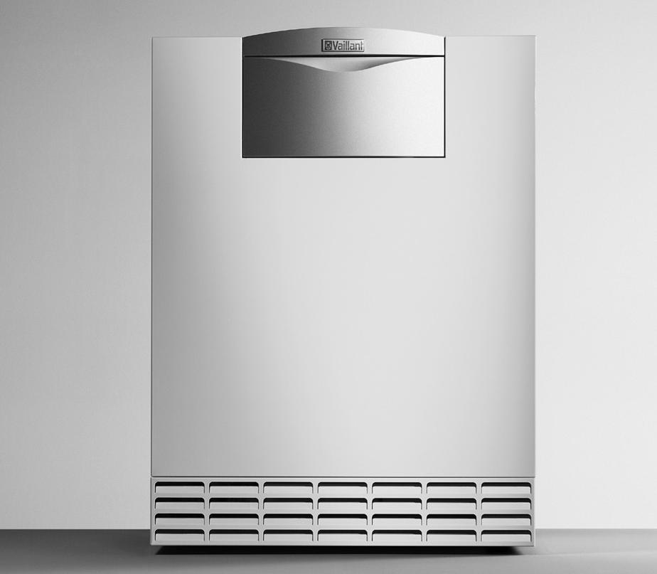
8 Operation 4 4 Operation 4. Overview of the operating elements The operating elements are accessible after folding up the upper section () and folding down the lower section () of the switching field cover. The operating elements have the following functions: Display for indication of the current operating mode or specific additional information "i" button for calling up information 3 Controller (accessory) 4 Button for switching the unit on and off. 5 "+" button for moving forward in the display (for adjustment and troubleshooting by the engineer); Inquiry of the current storage tank temperature in normal mode, if a storage tank sensor is connected. 6 "-" button for moving backwards in the display (for adjustment and troubleshooting by the engineer) 7 "Reset" button for resetting certain faults 8 Rotary knob for setting the heating feed temperature 9 Rotary knob for setting the storage tank temperature Digital Information and Analysis System (DIA- System) Fig. 4. Opening the door in the cover Fig. 4.3 Display of DIA-System Fig. 4. Controls 4 Your unit is fitted with a Digital Information and Analysis System (DIA-System). This system provides information on the operating status of your appliance and helps you deal with problems. In normal operation of the unit, the display () of the DIA-System shows the current heating feed temperature (45 C in the example). In the event of a fault, an error code appears instead of the temperature. You can also see the following information from the symbols displayed: Operating manual atmocraft GB 7
9 4 Operation Display of the current heating feed temperature or display of a status or fault code Flue problem Flue problem Permanently on: Heating operation active Flashing: Burner lockout time active Hot water preparation active Permanently on: Operating mode storage tank charging in readiness Flashing: Storage tank charging is in operation Burner on Heating pump in operation Actuating internal gas valve Flame with cross: Fault during burner operation; Unit is switched off Flame without cross: Burner operation normal Check the filling pressure of the installation using the pressure gauge (, not included). For the heating system to operate properly, the pointer on the pressure gauge () must be between.0 and.0 bar filling pressure. If it is below 0.75 bar, please top up the water (see Section 4.8.7). If the heating system extends over several storeys, the system may require a higher filling pressure. Ask your engineer for details. 4.3 Start-up Risk of damage! The main switch may only be turned on if the heating system is sufficiently full of water (see Section 4..). If this is not complied with, damage to the pump and heat exchanger may occur. 4. Preparing for initial operation 4.. Opening the shut-off valves The shut-off valves are not included in the scope of supply of your unit. They are fitted by your heating engineer in the installation. He should show you the location and how to operate these components. Open the gas stop cock by depressing and turning it anticlockwise as far as it will go. Check that the service valves in the feed and the return are open. Fig. 4.5 Switch the unit on 4.. Checking the system pressure 3 4 Use the main switch () to switch the appliance on and off: I: "ON" 0: "OFF" When the main switch () is in the "I" position the unit is switched on. On the display (), the standard read-out of the Digital Information and Analysis System Systems is shown (for the details see Section 4.). 0 6 bar 5 To adjust the appliance according to your requirements, read sections 4.4, and 4.5, which describe the setting options for hot water supply and heating. Fig. 4.4 Checking the filling pressure of the heating installation (pressure gauge not included) 8 Operating manual atmocraft
10 Operation 4 Risk of damage! The frost protection and monitoring systems are only active when the main switch of the appliance is in the "I" position and it is not disconnected from the mains power supply. To ensure that these protection devices remain active, switch your boiler on and off using the controller (see the corresponding operating manual). Section 4.9 describes how to take your gas boiler out of commission. 4.4 Settings for hot water preparation 3 Danger of calcium deposit build-up. If your water hardness is more than.79 mol/m 3 (0 dh), do not turn the knob (3) further than the middle position Drawing hot water Open one of the hot water taps at one of the water draw-off positions (hand-wash basin, shower, bath etc.). The hot water is drawn off from the integrated hot water storage tank. If the water in the tank falls below the set temperature, the appliance starts up automatically and reheats it. During the charging process of the storage tank the read-out in the display () flashes, see Figure 4.6. When the storage tank temperature that you have set is achieved, the unit switches off automatically. The pump continues to run for a short while Switching off the storage tank operation mode On the atmocraft boilers with connected hot water storage tanks you can switch the storage tank charging system off, whilst continuing to operate the heating system. To do this, turn the rotary knob (3) for setting the hot water temperature all the way to the left, see Figure 4.6. The frost protection function for the storage tank remains active. A storage tank temperature of 5 C is shown in the display (), for approx. 5 seconds. Fig. 4.6 Adjusting the storage tank temperature (only if a hot water storage tank is included) For hot water preparation using an atmocraft boiler, a hot water tank must be connected to the boiler. Proceed as follows to adjust it: Turn the rotary knob (3) to the desired temperature. In doing this: Turning all the way to the left, frost protection 5 C Minimum set water temperature 40 C Turning all the way to the right Maximum set water temperature 70 C. When setting the desired temperature, the value is shown on the display () of the DIA-System. After approx. five seconds the display returns to standard mode (the current heating feed temperature). We recommend a setting of 60 C for economic and hygienic reasons (e.g. Legionella). Operating manual atmocraft GB 9
11 4 Operation 4.5 Settings for heating 4.5. Setting the flow temperature (when using a controller) 4.5. Setting the flow temperature (no controller connected) Fig. 4.7 Setting the feed temperature when using a controller To comply with the regulations concerning the energysaving requirements of heating-technology installations and hot water installations (heating installation regulations - HeizAnlV), your heating system must be fitted with a weather-controlled controller or a room-temperature controller. In this case, the following setting must be undertaken: Turn the rotary knob () for setting the heating feed temperature all the way to the right. The flow temperature is automatically adjusted by the controller (for information see its operating manual). Your heating engineer can provide information concerning the control system fitted to your heating system. Fig. 4.8 Feed temperature setting without heating controller If there is no external controller, set the flow temperature using the knob () according to the outside temperature. We recommend the following settings: Left position (but not all the way) in spring and autumn: Outside temperature 0 to 0 C Mid-position setting in reasonably cold weather: Outside temperature 0 to 0 C Right position in very cold weather: Outside temperature 0 to 5 C When setting the desired temperature, the value is shown on the display () of the DIA-System. After five seconds the display returns to standard mode (the current heating flow temperature). Normally you can adjust the knob () continuously up to a feed temperature of 75 C. However, if higher temperatures can be set on your appliance, your engineer has made adjustments so that you can operate the heating system at higher feed temperatures up to 85 C. 0 Operating manual atmocraft
12 Operation Switching off heating (summer operation) 4.7 Status displays Fig. 4.9 Switching off heating (summer operation) You can switch off the heating in summer without switching off the hot water supply. Turn the rotary knob () for setting the heating feed temperature all the way to the left. 4.6 Setting a room thermostat or weather compensator Fig. 4.0 Setting the room temperature controller/weather controlled regulator Fig. 4. Status displays The status display provides information on the operational condition of your boiler. Press the "i" button () to activate the status displays. The display () then shows the individual status codes, e.g. "S. 4" for burner operation. The table below explains the most important status codes. In switching phases, for example on starting up again after the flame was extinguished, the status message "S." briefly appears. Press the "i" button () again to switch the display back to normal mode. Display Meaning Displays during heating operation S. 0 No heat required S. Heating pump supply S. 3 Heating ignition S. 4 Heating burner on S. 7 Heating pump run-out S. 8 Burner lock after heating mode Displays in storage tank operation S. 0 Storage cycle mode active S.3 Storage tank charging ignition S. 4 Storage tank charging burner on S.7 Storage tank charging pump overrun S.8 Burner blocking time after storage tank charging Table 4. Status codes and their meaning Set the programmable room thermostat (), weather compensator or heater thermostat valves () according to the operating manuals for these accessories. Operating manual atmocraft GB
13 4 Operation Display Meaning Displays of system conditions S.30 No heat requirement from -point controller S.3 Summer mode active S.34 Frost protection heating active S.36 No heat requirement controller from continuous controller S.39 Switch on "unit thermostat" terminal has interrupted S.4 Exhaust gas flap contact on accessories is open S.5 The unit has detected exhaust gas emission and is within the 30 second continuous tolerance time S.5 Appliance is within the 0-minute waiting period of the operation block function due to exhaust gas emission Table 4. Status codes and their meaning (continuation) 4.8 Troubleshooting If you have problems with your gas boiler, you can check the following points yourself: No hot water, heating stays cold; Appliance does not start: - Is your house stop cock in the gas supply or the gas stop on the appliance open (see Section 4.)? - Is the power supply switched on? - Is the main switch on the gas boiler switched on (see Section 4.3)? - Is the rotary knob for setting the storage tank temperature turned to the far left position, in other words to frost protection (see Section 4.4)? - Is the filling pressure of the heating system sufficient (see Section 4.8.)? - Is there air in the heating system (see Section 4.8.)? - Is there an ignition problem (see Section 4.8.3)? Hot water operation, no problem; Heating does not start: - Is there a requirement for heating from the external controller (e.g. type VRC controller) (see Section 4.7)? - Has an external monitor switched off the system (see Section 4.7)? Heating, no problem; no hot water: - Is the hot water preparation blocked by an external controller (see controller instructions)? If when simultaneously depressing the buttons "+" and "-" no hot water is shown, then the sensor is faulty or is not connected. Inappropriate alterations can cause damage! If your gas boiler still does not work properly after you have checked the above points, you must call a suitably qualified heating engineer for help Faults during heating operation In the event of a fault on the boiler, a fault code will be shown on the display. In the case of the faults described above you can try to resolve the fault yourself. In the event of other faults in the heating system an authorised heating engineer must be consulted to check the system Problems due to lack of water Fig. 4. Releasing after water shortage The device switches to "Fault" if the filling pressure in the heating system is too low. This fault is displayed by the fault code "F.0". Remove the front cover. Release the STB by pushing the pin (). Reset the electronic system by pushing the "Reset" button (). Operating manual atmocraft
14 Operation 4 The unit can only be re-started if the heating system has sufficient water in it (see Section 4.8.7). If the fault signal F.0 is shown repeatedly, an authorised heating engineer must be consulted to carry out a check of the system Fault caused by exceeding the temperature Ignition problems Abb. 4.4 Releasing after STB switch-off Fig. 4.3 Fault resolution If the burner fails to ignite after three attempts, the device does not start up and switches to "Fault". This is indicated by the fault code "F.8" or "F.9" in the display. First check whether the stop-cock in the gas line is open. Automatic ignition can only take place after you manually reset the fault. To reset the fault, press the "reset" button () and hold it down for approx. one second. Inappropriate alterations can cause damage! If your gas boiler still does not start after the third attempt, you must call a suitably qualified heating engineer for help. Your boiler is equipped with a safety temperature limiter (STB) which automatically switches off the boiler if the temperature gets too hot. This fault is displayed by the fault code "F.0". Remove the front cover. Release the STB by pushing the pin (). Reset the electronic system by pushing the "Reset" button (). If the fault signal F.0 is shown repeatedly, an authorised heating engineer must be consulted to carry out a check of the system Faults with the exhaust gas removal The Vaillant atmocraft units can be equipped with an exhaust gas sensor (accessories). If the exhaust gases are not removed properly, the unit switches off temporarily in order to prevent the escape of exhaust gas into the room where the boiler is located. The display shows the symbol "Fault in air/exhaust gas route". The unit starts up again automatically after approx. 5-0 minutes after this switch-off. After repeated switch-off (max. three failed attempts) the unit does not start up again. The error message "F.36" appears in the display. Operating manual atmocraft GB 3
15 4 Operation Danger! If the unit still does not start after repeating the fault resolution process three times, then an authorised heating engineer must be consulted to check the unit Filling unit/heating installation 3 4 Open all thermostatic valves in the installation. Connect the filling tap of the installation to a cold water draw-off valve with a hose (your heating engineer should have shown you the filling fittings and explained the filling and draining of the system). Open the filling cock slowly. Turn the filling cock and the tap on slowly and add water until the required installation pressure is shown on the pressure gauge (). Turn the tap off. Vent all the radiators. Then check the system pressure on the pressure gauge () and add more water if necessary. Close the filling cock and remove the filling hose Shut-down 0 6 bar Fig. 4.5 Checking the filling pressure of the heating installation (pressure gauge not included) For the heating system to operate properly, the pointer on the pressure gauge () must be between.0 and.0 bar filling pressure when the system is cold. If it is less than 0.75 bar, then water should be added. If the heating system extends over several storeys, the system may require a higher filling pressure. Ask your engineer for details. Fig. 4.6 Switching the unit off Danger of damage to the gas boiler. Use only clean tap-water to top up the heating system. The addition of chemicals such as e.g. frost and corrosion prevention materials (inhibitors) is not permitted. Otherwise it could result in damage to seals and diaphragms as well as noises in the heating operation. Vaillant assumes no liability for this and such consequential damages. To shut down your gas wall boiler, turn the main switch () to the "0" position. The frost protection and monitoring systems are only active when the main switch of the appliance is in the "I" position and it is not disconnected from the mains power supply. To ensure that these protection devices remain active, switch your gas boiler on and off in normal mode using the controller (see the corresponding operating manual). To fill up and to refill the heating system, you can normally use tap water. However in exceptions, the water quality might not be suitable for filling in the heating system (heavily corrosive or extremely calciferous water). In a case such as this you should please contact your authorised heating engineer. Proceed as follows to fill the installation: 4 Operating manual atmocraft
16 Operation 4 For longer periods of shut-down (e.g. holiday periods), the gas stop-cock and the cold water stop-cock should be switched off. In this connection, please refer to the instructions in Chapter 4.0 concerning frost protection. The shut-off valves are not included in the scope of supply of your unit. They are fitted by your heating engineer in the installation. The position and handling of these components should be described to you. 4.0 Frost protection The heating system and water pipes are sufficiently protected against frost if the heating system remains on and the rooms are sufficiently heated while you are away. The frost protection and monitoring systems are only active when the main switch of the appliance is in the "I" position and it is not disconnected from the mains power supply. Danger of damage to the gas boiler by frost prevention material. Addition of frost preventative medium to the heating water is not permitted. Otherwise it could result in damage to seals and diaphragms as well as to noises in the heating operation. Vaillant assumes no liability for this and such consequential damages Frost protection function The gas boiler is equipped with a frost protection function: If the heating feed temperature falls below 5 C with the main switch on, the unit starts up and heats the unit heating circuit to approx. 35 C. Danger of freezing up of parts of the entire installation. The frost protection system cannot guarantee flow through the entire heating system Frost protection by draining Another way to protect the heating system and the appliance from frost is to drain them. You must ensure that the system and the appliance are completely drained. All cold and hot water pipes in the house and the hot water storage tank connected in the building must also be drained. Contact your heating engineer. 4. Maintenance and customer service 4.. Inspection and maintenance Permanent operational readiness, reliability and a long service life require inspections and maintenance work to regularly carried out by a heating engineer. Danger! Danger of property damage and personal injury from improper handling! Never attempt to perform maintenance or repairs on the gas boiler yourself. Assign an approved qualified servicing company with this work. We recommend making a maintenance agreement. The operational reliability of the device can be impaired, resulting in damage to property or personal injury, if maintenance work is not carried out. Regular servicing ensures maximum efficiency and economical operation of your gas boiler. 4.. Maintenance requirement indicator The heating engineer can adjust a maintenance requirement display in your boiler. If this function is activated, the read-out "SER" appears in the display on your boiler as soon as maintenance becomes necessary. When this display appears you should inform your heating engineer and he should perform the maintenance work. If this function is not activated, and a maintenance requirement display is not shown, the boiler should be serviced at least once a year. Operating manual atmocraft GB 5
17 4 Operation 4..3 Chimney sweep measurements The measurement and checking work should be carried out only by the chimney sweep. 7 6 Fig. 4.7 Switch on the chimney sweep mode Proceed as follows to perform the measurements: Activate the chimney sweep mode by simultaneously pushing the buttons "+" (6) and "-" (7) on the DIA System. The measurements should be taken at the earliest after minutes of operation of the unit. By simultaneous pushing of buttons "+" (6) and "-" (7) you can exit the measuring mode. The measuring mode will also be ended if no button is pushed within a 5 minute period. 6 Operating manual atmocraft
For the owner. Operating manual. ecotec plus 937. Gas condensing storage combination boiler VUI
 For the owner Operating manual ecotec plus 937 Gas condensing storage combination boiler GB VUI Contents Appliance characteristics Recommended accessories Contents Appliance characteristics... Recommended
For the owner. Operating manual. ecotec. Gas wall boilers with condensing appliance technology VU 466/4 VU 656/4
 For the owner Operating manual ecotec Gas wall boilers with condensing appliance technology GB VU 466/4 VU 656/4 Contents Appliance characteristics Recommended accessories Contents Appliance characteristics...
Operating instructions. For the operator. Operating instructions. ecotec. Gas fired wall hung high efficiency boiler.
 Operating instructions For the operator Operating instructions ecotec Gas fired wall hung high efficiency boiler Channel Islands Inhaltsverzeichnis Inhaltsverzeichnis 1 Notes on the documentation...3 1.1
Operating instructions
 Operating instructions For the operator Operating instructions HOME SYSTEM GB, IE Publisher/manufacturer Vaillant GmbH Berghauser Str. 40 D-42859 Remscheid Tel. +49 21 91 18 0 Fax +49 21 91 18 28 10 info@vaillant.de
Operating instructions
 Operating instructions Capriz 2 24c 28c GB, IE Contents Contents 1 Safety... 3 1.1 Action-related warnings... 3 1.2 Intended use... 3 1.3 General safety information... 4 2 Notes on the documentation...
Operating instructions
 The energy you need Operating instructions Betacom 3 24c -A (H-GB) 30c -A (H-GB) GB, IE Contents Contents 1 Safety... 3 1.1 Action-related warnings... 3 1.2 Intended use... 3 1.3 General safety information...
Operating instructions
 Operating instructions For the operator Operating instructions ecotec plus Gas-fired wall-hung high-efficiency boiler GB, IE Publisher/manufacturer Vaillant GmbH Berghauser Str. 40 D-42859 Remscheid Telefon
ecotec pro Operating instructions Operating instructions For the operator GB, IE Gas-fired wall-hung high-efficiency boiler
 Operating instructions For the operator Operating instructions ecotec pro Gas-fired wall-hung high-efficiency boiler GB, IE Publisher/manufacturer Vaillant GmbH Berghauser Str. 40 D-42859 Remscheid Tel.
VIESMANN. Operating instructions VITODENS 050-W. for the system user. With constant temperature or weather-compensated control unit
 Operating instructions for the system user VIESMANN With constant temperature or weather-compensated control unit VITODENS 050-W 9/2014 Please keep safe. Safety instructions For your safety Please follow
ecotec plus boiler user guide
 boiler user guide Valliant boiler VU, VUW Operating instructions For the operator Operating instructions VU, VUW GB, IE Publisher/manufacturer Vaillant GmbH Berghauser Str. 40 D-42859 Remscheid Tel. +49
VIESMANN. Operating instructions VITODENS VITOPEND. for the system user. Heating system with Vitotronic 100 control unit for constant temperature mode
 Operating instructions for the system user VIESMANN Heating system with Vitotronic 100 control unit for constant temperature mode VITODENS VITOPEND 4/2007 Please keep safe. Safety instructions For your
Operating instructions
 Operating instructions Gas condensing boiler WARNING: If the information in this manual is not followed exactly, a fire or explosion may result causing property damage, personal injury or loss of life.
Ultracom 2. sxi. Instructions for Use. 12sxi. 18sxi. 30sxi. High Efficiency Condensing System Boilers. To be left with the user. G.C. No.
 Ultracom 2 sxi Instructions for Use To be left with the user 12sxi G.C. No. 41-019-12 18sxi G.C. No. 41-019-13 30sxi G.C. No. 41-019-14 High Efficiency Condensing System Boilers www.glow-worm.co.uk TABLE
Residential Gas Condensing Boiler Greenstar ZBR16/21/28/35/42-3A... ZWB28/35/42-3A...
 70 80 99-00-O Residential Gas Condensing Boiler ZBR//8/35/4-3A... ZWB8/35/4-3A... 70 80 993 (03/03) CA/US Operating Instructions Contents Contents Key to symbols and safety instructions............................
O. Gas boiler. Gaz 6000 W WBN H-E-N/L-S2400. Operating instructions for the end customer (2017/09) en
 en") 8 716 473 216-00.3O Gas boiler WBN 6000-30-H-E-N/L-S2400 Operating instructions for the end customer en 2 Contents Contents 1 Key to symbols and safety instructions................... 2 1.1 Key to symbols..................................
8 716 473 216-00.3O Gas boiler WBN 6000-30-H-E-N/L-S2400 Operating instructions for the end customer en 2 Contents Contents 1 Key to symbols and safety instructions................... 2 1.1 Key to symbols..................................
Installation instructions. For the heating engineer. Installation instructions. timeswitch VTS 160 GB, IE
 Installation instructions For the heating engineer Installation instructions timeswitch VTS 160 GB, IE Table of contents Table of contents 1 Notes on the installation instructions...4 1.1 Observing other
VIESMANN. Operating instructions VITODENS 100-W. for the system user
 Operating instructions for the system user VIESMANN Heating system with control unit for constant temperature or weather-compensated mode VITODENS 100-W 1/2012 Please keep safe. Safety instructions For
Supplement to operating and installation manual no for the VR 81 remote control unit
 Supplement to operating and installation manual no. 0020044392 for the VR 81 remote control unit The VR 81/2 remote control unit can be used together with the VRC 430/VRC 430f and VRC 470 compensator types.
ir-range 8G /03.15 Changes reserved.
 U s e r m a n u a l ic-range is-range ir-range 8G.52.80.00/03.15 Changes reserved. Contents 1. Introduction...3 2. Safety...5 3. Boiler description...6 4. Display and functions...7 4.1 DHW and Heating
VIESMANN. Operating instructions VITODENS 111-W. for the system user
 Operating instructions for the system user VIESMANN Heating system with control unit for constant temperature or weather-compensated mode VITODENS 111-W 4/2012 Please keep safe. Safety instructions For
/2010 US/CA
 6 720 646 148-11/2010 US/CA (en) For the user User s Instructions Condensing gas boiler Logamax plus GB162-L.B. 80 kw/100 kw Please read thoroughly before operating This manual is available in the English
Operating instructions
 Operating instructions Gas-fired condensing boiler Logano plus GB312 For the user Please read carefully before use 7 747 009 296-01/2007 EN Contents 1 For your safety..............................................
Residential Gas Condensing Boiler Greenstar combi 100 p / 151 p ZWB28-3A... ZWB42-3A...
 Residential Gas Condensing Boiler Greenstar combi 00 p / 5 p ZWB8-3A... ZWB4-3A... Operating Instructions 708733 (07/04) US/CA Contents Contents Explanation of symbols and safety instructions.......................
condens Instructions for Use Betacom 2 24 G.C. No Betacom 2 28 G.C. No
 condens Instructions for Use Betacom 2 24 G.C. No. 47-019-16 Betacom 2 28 G.C. No. 47-019-17 table of contents READ CAREFULLY BEFORE USING 1 Read me...3 1.1 Welcome... 3 1.2 Guarantee Pack... 3 1.3 Servicing...
USERS MANUAL FOR GAS BOILERS
 USERS MANUAL FOR GAS BOILERS PLEASE READ THE MANUAL CAREFULLY: IT CONTAINS IMPORTANT INFORMATION REGARDING SAFETY, INSTALLATION, USE AND MAINTENANCE OF THE APPLIANCE MODELS: NOVADENS 24 NOVADENS 24C NOVADENS
USER INSTRUCTIONS & CUSTOMER CARE GUIDE Si II SERIES
 24-28Si II SERIES G.C. NUMBERS APPLIANCE NATURAL GAS L.P.G. 24Si II 47 311 65 47 311 66 28Si II 47 311 67 47 311 68 USER INSTRUCTIONS & CUSTOMER CARE GUIDE EXCELLENCE COMES AS STANDARD CONTENTS Page No.
Operating instructions Oil condensing boiler
 Operating instructions Oil condensing boiler COB COB-CS Boiler for heating Boiler with stratification cylinder Wolf GmbH Postfach 1380 D-84048 Mainburg Tel. +49-8751/74-0 Fax +49-8751/741600 Internet:
PLEASE LEAVE THIS INSTRUCTION WITH THE USER ECOMFORT PLUS 25 HE. User instructions
 GB PLEASE LEAVE THIS INSTRUCTION WH THE USER ECOMFORT PLUS 25 HE User instructions All descriptions and illustrations provided in this manual have been carefully prepared but we reserve the right to make
Format System 25 HE. User instructions. Please read the Important Notice within this guide regarding your boiler warranty
 UK ENSURE THAT THESE INSTRUCTIONS ARE LEFT FOR THE USER AFTER COMPLETION OF THE BENCHMARK SECTION Format System 25 HE User instructions 199838 Please read the Important Notice within this guide regarding
Vote for your Installer of the year at. 9/14, 14/19 & 19/24CBi. Worcester supports the Benchmark code of practice
 Vote for your Installer of the year at www.worcester-bosch.co.uk 9/14, 14/19 & 19/24CBi Worcester supports the Benchmark code of practice G. C. NUMBERS APPLIANCE NATURAL GAS LPG 9/14CBi 41 311 50 41 311
Operating instructions. For the operator. Operating instructions VRT 350. Room temperature-controlled controller GB, IE
 Operating instructions For the operator Operating instructions VRT 350 Room temperature-controlled controller GB, IE Legal information Document type: Product: VRT 350 Target group: Language: Operating
VIESMANN. Operating instructions VITODENS 100. for system users. Heating system with control unit for constant temperature operation
 Operating instructions for system users VIESMANN Heating system with control unit for constant temperature operation VITODENS 100 2/2005 Please keep safe Safety instructions For your safety Please follow
E-COMBI EVO E-SYSTEM EVO
 E-COMBI EVO E-SYSTEM EVO User s manual CONDENSING WALL-HUNG GAS BOILER G.C.N.:47-116-68 (24 kw) G.C.N.:47-116-69 (30 kw) G.C.N.:47-116-70 (38 kw) G.C.N.:41-116-39 (24 kw) G.C.N.:41-116-40 (30 kw) Country
Baxi Maxflow Combi FS
 Baxi Maxflow Combi FS Gas Fired Floor Standing Combination Boiler with Unvented Hot Water Storage Please keep these instructions safe. Should you move house, please hand them over to the next occupier.
User's Instructions. Alpha CB50
 User's Instructions Alpha CB50 Wall Mounted, Fan Assisted, Room Sealed, Gas Fired Combination Boiler with Unvented Hot Water Storage (From Boiler Serial No. 27B32500001) For Technical help or for Service
Baxi Maxflow Combi WM
 Baxi Maxflow Combi WM Gas Fired Wall Mounted Combination Boiler with Unvented Hot Water Storage Please keep these instructions safe. Should you move house, please hand them over to the next occupier. User
condens Instructions for Use Ultracom 2 35 Store G.C. No
 condens Instructions for Use Ultracom 2 35 Store G.C. No. 47-019-15 table of contents READ CAREFULLY BEFORE USING 1 Read me...3 1.1 Welcome... 3 1.2 Guarantee Pack... 3 1.3 Servicing... 3 1.4 Benchmark...
PLEASE LEAVE THIS INSTRUCTION WITH THE USER. Ecomfort 30 HE. User instructions
 GB PLEASE LEAVE THIS INSTRUCTION WITH THE USER Ecomfort 30 HE User instructions CONTENTS OPERATING INSTRUCTIONS FOR THE USER 1.1 INTRODUCTION.................................................................................
Performa 24. Gas Fired Wall Mounted Combination Boiler. User s Operating Instructions
 Performa Gas Fired Wall Mounted Combination Boiler User s Operating Instructions Please keep these instructions safe. Should you move house, please hand them over to the next occupier. Natural Gas Potterton
WHE 2.24 / WHE 2.24 FF
 EN Wall-hung gas boilers WHE 2.24 WHE 2.24 FF User Guide 300011777-001-C . Contents 1 Introduction.............................................................................3 1.1 Symbols used...........................................................................................3
User Manual FLOWMAX-90. for model. Condensing water heater 85,000 BTU. Installation, operating, commissioning and maintenance instructions.
 User Manual for model FLOWMAX-90 Condensing water heater 85,000 BTU WARNING If the information in these instructions is not followed exactly, a fire or explosion may result, causing property damage, personal
Operating Instructions
 Operating Instructions Low Emissions and High Efficiency Condensing Oil Boiler DANGER! If these instructions are not followed exactly, a fire or explosion may be caused with serious property damage or
i 24, i 30, i 35 combination boilers USER GUIDE For Installation Guide see reverse of book UIN A05 October 2017
 24 1 2 23 3 4 5 20 6 I 19 7 18 8 9 15 14 11 13 12 i 24, i 30, i 35 combination boilers USER GUIDE For Installation Guide see reverse of book i 24 OFF MAX E STATUS BURNER RESET MIN PRE MIN MAX HEAT PREHEAT
I n s t r u c t i o n m a n u a l f o r b u i l t - i n h o o d. Model code: BORA600
 I n s t r u c t i o n m a n u a l f o r b u i l t - i n h o o d Model code: BORA600 Contact Caple on 0844 8003830 or for spare parts www.4caple.co.uk 1 Y O U R A P P L I A N C E Thank you for buying your
Baxi Bahama 100. Gas Fired Wall Mounted Combination Boiler. User s Operating Instructions
 Baxi Bahama 100 Please keep these instructions safe. Should you move house, please hand them over to the next occupier. Gas Fired Wall Mounted Combination Boiler User s Operating Instructions Natural Gas
User s Information Manual
 User s Information Manual Series 2 Models 1000-2000 MBH Commercial Condensing Gas-fired water boilers If the information in this manual is not followed exactly, a fire or explosion may result, causing
Baxi System 100 HE Plus. User s Operating Instructions. Wall Mounted Powered Flue Condensing Gas Fired Central Heating Boiler
 User s Operating Instructions Baxi System 100 HE Plus Wall Mounted Powered Flue Condensing Gas Fired Central Heating Boiler Please keep these instructions safe. Should you move house, please hand them
Osprey 2 CFL
 Osprey 2 CFL 125-150 - 180-220 Gas Fired Floor Standing Boiler Users Operating Instructions Please leave these instructions with the user Natural Gas Potterton Osprey 2 CFL 125 G.C.N o 41 590 54 Potterton
T UNI 7000 F. Operating instructions For the user (2006/05) AU/GB
 AU/GB") 6 720 648 662-00.1T UNI 7000 F Operating instructions For the user AU/G 2 Contents Contents Contents 2 1 Safety information and explanation of symbols 3 1.1 For your safety 3 1.2 Explanation of symbols
6 720 648 662-00.1T UNI 7000 F Operating instructions For the user AU/G 2 Contents Contents Contents 2 1 Safety information and explanation of symbols 3 1.1 For your safety 3 1.2 Explanation of symbols
MURELLE EV HE 25/55-30/55
 UK ENSURE THAT THESE INSTRUCTIONS ARE LEFT FOR THE USER AFTER COMPLETION OF THE BENCHMARK SECTION MURELLE EV HE 25/55-30/55 User instructions 199838 Please read the Important Notice within this guide regarding
iheat 25c iheat 30c iheat 35c
 iheat 25c iheat 30c iheat 35c Combination Condensing Boilers User Instructions G.C. NUMBER iheat 25c N 47-260-16 iheat 30c N 47-260-17 iheat 35c N 47-260-18 These instructions should be left with the user
Baxi Combi 80Eco. Gas Fired Wall Mounted Combination Boiler. User s Operating Instructions
 Baxi Combi 80Eco Please keep these instructions safe. Should you move house, please hand them over to the next occupier. Gas Fired Wall Mounted Combination Boiler User s Operating Instructions Natural
allstor buffer cylinder Instructions for use Instructions for use For the operator Publisher/manufacturer Vaillant GmbH
 Instructions for use For the operator Instructions for use allstor buffer cylinder GB Publisher/manufacturer Vaillant GmbH Berghauser Str. 40 D-42859 Remscheid Telefon 021 91 18 0 Telefax 021 91 18 28
Users Manual. Gas wall hung Boiler condensing Buderus /S. Please read thoroughly before operating the unit
 7215 3200-02/2006 GB (EN) For the user Users Manual Gas wall hung Boiler condensing Buderus 500-24/S Please read thoroughly before operating the unit Introduction Please read these instructions and follow
Greenstar 12i/24i System
 USER INSTRUCTIONS & CUSTOMER CARE GUIDE Greenstar 12i/24i System WALL HUNG GAS-FIRED CONDENSING SYSTEM BOILER FOR SEALED CENTRAL HEATING SYSTEMS & INDIRECT FED DOMESTIC HOT WATER THIS BOILER IS USED WITH
USER INSTRUCTIONS & CUSTOMER CARE GUIDE HIGHFLOW 400 ELECTRONIC SERIES
 HIGHFLOW 400 ELECTRONIC SERIES G.C. NUMBERS APPLIANCE NATURAL GAS L.P.G. Fanned Flue (RSF) 47 311 61 47 311 64 Balanced Flue (BF) 47 311 62 Open Flue (OF) 47 311 63 USER INSTRUCTIONS & CUSTOMER CARE GUIDE
User manual. Logano GC 124 II. Gas boiler
 User manual Gas boiler WARNING! If the information in this manual is not followed exactly, a fire or explosion may result causing property damage, personal injury or loss of life. B Do not store or use
User Guide and Important Warranty Information. Promax System HE Plus A Range. Condensing System Boiler
 You can rely on User Guide and Important Warranty Information Promax System HE Plus A Range Condensing System Boiler Please keep these instructions in a safe place. If you move house, please hand them
User Guide and Important Warranty Information. Suprima HE Range. Condensing Central Heating Boiler. You can rely on
 You can rely on User Guide and Important Warranty Information Suprima HE Range Condensing Central Heating Boiler Please keep these instructions in a safe place. If you move house, please hand them over
Operation manual. Wall-mounted condensing boiler D2CND024A1AA D2CND024A4AA D2TND012A4AA D2TND018A4AA D2TND024A4AA
 D2CND024A1AA D2CND024A4AA D2TND012A4AA D2TND018A4AA D2TND024A4AA English Table of Contents Table of Contents 1 Introduction 2 1.1 About the unit... 2 1.2 About the documentation... 2 1.2.1 Meaning of warnings
User Guide. EcoBlue Advance Heat Gas Fired Wall Mounted Condensing Boiler
 United Kingdom en User Guide Gas Fired Wall Mounted Condensing Boiler EcoBlue Advance Heat 13-16 - 19-25 - 30 Please keep these instructions in a safe place. If you move house please hand them over to
User Manual for model
 User Manual for model RKA 24 /20 Wall mounted storage combi boiler premix condensing boiler CE 0694 Technical specification RADIANT BRUCIATORI S.p.A. Montelabbate RKA 24.20 - RAD - ING - MAN.UT - 1309.1
User Manual RBS 24. for model CE series ENERGY. Wall mounted instantaneous combi boiler room sealed chamber
 User Manual for model RBS 24 series ENERGY Wall mounted instantaneous combi boiler room sealed chamber CE 0694 RBS 24 - SERIE ENERGY - RAD - ING - MAN.UT - 1407.1 - DIGITECH TR - MIAH6 - E04 Technical
The guarantee on this appliance is valid for 12 months from the first day of installation.
 Users Manual Dear Customer, Thank you for choosing an ARISTON boiler. We guarantee that your boiler is a reliable and technically sound product. This Users Manual provides detailed instructions and recommendations
USER GUIDE VOGUE COMBI GEN2 C26 C32 C40
 USER GUIDE VOGUE COMBI GEN2 C26 C32 C40 When replacing any part on this appliance, use only spare parts that you can be assured conform to the safety and performance specification that we require. Do not
Operating instructions
 6304 0307 04/2005 US For the installer Operating instructions Sealed combustion boiler Logano GA24 SC and atmospheric boiler Logano G24X II/SP If these instructions are not followed exactly, a fire or
VR 90 Remote control unit
 For heating engineer/owner Operating and Installation Manual VR 90 Remote control unit Bus-modular control system GB VR 90 For the operator Operating manual VR 90 Remote control unit Bus modular control
USERS GUIDE 24, 30. For installation guide see reverse of book
 USERS GUIDE 24, 30 For installation guide see reverse of book When replacing any part on this appliance, use only spare parts that you can be assured conform to the safety and performance specification
INSTRUCTION FOR THE USER THC V E OIL BLU
 INSTRUCTION FOR THE THC V E OIL BLU CONTENTS General safety information 4 Precautions 4 Control panel 5 Mode selection 8 User levels 10 Start-up 12 Temporary shutdown 15 Preparing for extended periods
System s30. User Guide FAN POWERED HIGH EFFICIENCY MODULATING DOMESTIC CONDENSING GAS SYSTEM BOILER
 System s30 User Guide FAN POWERED HIGH EFFICIENCY MODULATING DOMESTIC CONDENSING GAS SYSTEM BOILER When replacing any part on this appliance, use only spare parts that you can be assured conform to the
Combi Eco Elite Range. User s Guide and Important Warranty Information
 User s Guide and Important Warranty Information Combi Eco Elite Range Please keep these instructions in a safe place. If you move house, please hand them over to the next occupier. Baxi Heating UK Ltd
User s Operation Instructions & Important Warranty Information
 United Kingdom en User s Operation Instructions & Important Warranty Information High-efficiency wall-hung boilers Baxi Avanta Plus 18s - 24s - 30s 24c - 28c - 35c - 39c Please keep these instructions
For the owner and the heating engineer. Operating and Installation Manual VRC 400. Programmable weather compensator with separat HW time control
 For the owner and the heating engineer Operating and Installation Manual VRC 400 Programmable weather compensator with separat HW time control GB Contents Contents Notes on the documentation..... 4 Symbols
E-Combi One E-System ONE
 discover more @ariston.com G.C.N.: 47-116-83 (24 kw) G.C.N.: 47-116-84 (30 kw) G.C.N.: 41-116-47 (24 kw) G.C.N.: 41-116-48 (30 kw) E-Combi One E-System ONE USER S MANUAL CONDENSING WALL-HUNG GAS BOILER
Combi C30 & C35. User Guide FAN POWERED HIGH EFFICIENCY MODULATING DOMESTIC CONDENSING GAS COMBINATION BOILER
 Combi C30 & C35 User Guide FAN POWERED HIGH EFFICIENCY MODULATING DOMESTIC CONDENSING GAS COMBINATION BOILER When replacing any part on this appliance, use only spare parts that you can be assured confirm
INSTALLATION AND MANINTENANCE INSTRUCTIONS
 INSTALLATION AND MANINTENANCE INSTRUCTIONS Appr. Nr. A 9503 T - 0085 AQ 0765 PEGASUS F2 T HIGH EFFICIENCY GAS-FIRED CAST-IRON BOILERS Models 51-68 - 85-102 2 Contents 1. General technical data 2. Dimensional
USER GUIDE LOGIC HEAT H
 USER GUIDE LOGIC HEAT H 12 15 18 24 30 When replacing any part on this appliance, use only spare parts that you can be assured conform to the safety and performance specification that we require. Do not
VIESMANN. Installation and service instructions VITOTROL 200 RF. for contractors. Vitotrol 200 RF. Wireless remote control for one heating circuit
 Installation and service instructions for contractors VIESMANN Vitotrol 200 RF Wireless remote control for one heating circuit For applicability, see the last page VITOTROL 200 RF 3/2011 Please keep safe.
Vote for your Installer of the year at HEATSLAVE
 Vote for your Installer of the year at www.worcester-bosch.co.uk HEATSLAVE 12/14, 15/19, 20/25, 26/32 FLOOR-STANDING OIL-FIRED COMBINATION BOILERS FOR CENTRAL HEATING AND MAINS-FED DOMESTIC HOT WATER USER
Logic+ Combi
 USER GUIDE Logic+ Combi 24 30 35 When replacing any part on this appliance, use only spare parts that you can be assured conform to the safety and performance specification that we require. Do not use
User s Information Manual
 User s Information Manual Series 3 Models 550 and 750 MBH Commercial Condensing Gas-fired water boilers If the information in this manual is not followed exactly, a fire or explosion may result, causing
User s Information Manual
 User s Information Manual Model NPE-24AWE NPE-24SWE NPE-32AWE NPE-32SWE Condensing Water Heater These appliances are for use with natural gas or LPG. (An LPG conversion kit is included with the water heater.)
Greenstar 25Si/30Si USER INSTRUCTIONS & CUSTOMER CARE GUIDE
 USER INSTRUCTIONS & CUSTOMER CARE GUIDE Greenstar 25Si/30Si WALL HUNG GAS-FIRED CONDENSING COMBINATION BOILER FOR SEALED CENTRAL HEATING SYSTEMS & DOMESTIC HOT WATER THIS BOILER IS USED WITH NATURAL GAS
USER GUIDE VOGUE MAX SYSTEM
 USER GUIDE VOGUE MAX SYSTEM 15 18 26 32 When replacing any part on this appliance, use only spare parts that you can be assured conform to the safety and performance specification that we require. Do not
Operating and Installation Manual VRC 430f. Weather compensator controller with radio transmission. For the operator / for the heating engineer
 For the operator / for the heating engineer Operating and Installation Manual VRC 430f Weather compensator controller with radio transmission GB VRC 430f For the operator Operating instructions VRC 430f
Users manual. Buderus /29/43/60 and Buderus T25/29T25 H/V. Wall-mounted condensing gas boiler. For the user
 Users manual Wall-mounted condensing gas boiler Buderus 800-24/29/43/60 and Buderus 800-24T25/29T25 H/V For the user Please read thoroughly before operating the unit 722 3700 (03/200) GB Preface Introduction
USERS GUIDE. LOGIC+ Combi 24, 30, 35
 USERS GUIDE LOGIC+ Combi 24, 30, 35 When replacing any part on this appliance, use only spare parts that you can be assured conform to the safety and performance specification that we require. Do not use
GREENSTAR HIGHFLOW 440/550CDi
 FLOOR STANDING RSF GAS-FIRED CONDENSING COMBINATION BOILER GREENSTAR HIGHFLOW 440/550CDi FOR SEALED CENTRAL HEATING SYSTEMS AND MAINS FED DOMESTIC HOT WATER THE APPLIANCE IS FOR USE WITH NATURAL GAS OR
For the operator/for the heating engineer. Operating and Installation Manual VRC 430. Weather compensator VRC 430
 For the operator/for the heating engineer Operating and Installation Manual VRC 430 Weather compensator GB VRC 430 For the operator Operating Manual VRC 430 Weather compensator VRC 430 Contents Appliance
FORMAT DGT HE. User instructions. Please read the Important Notice within this guide regarding your boiler warranty
 UK ENSURE THAT THESE INSTRUCTIONS ARE LEFT FOR THE USER AFTER COMPLETION OF THE BENCHMARK SECTION FORMAT DGT HE 199838 User instructions Please read the Important Notice within this guide regarding your
GREENSTAR HEATSLAVE II EXTERNAL 12/18, 18/25 & 25/32
 USER INSTRUCTIONS & CUSTOMER CARE GUIDE FLOOR STANDING OIL FIRED CONDENSING BOILER CONVENTIONAL FLUE & ROOM SEALED FLUE GREENSTAR HEATSLAVE II EXTERNAL 12/18, 18/25 & 25/32 FOR SEALED CENTRAL HEATING SYSTEMS
Operating instructions
 6 720 804 891 2012/10 EN-US For the installer Operating instructions Sealed combustion boiler Logano GA124 SC If these instructions are not followed exactly, a fire or explosion may be caused with serious
24/30/38. E-Combi. CONDENSING WALL HUNG COMBINATION BOILER G.C.N : (24 kw) G.C.N : (30 kw) G.C.N : (38 kw)
 G.C.N : (30 kw) G.C.N : (38 kw)") E-Combi 24/30/38 E-System 24/30 CNDENSNG WALL HUNG CMBNATN BLER G.C.N : 47-11 - 2 (24 kw) G.C.N : 47-11 - 3 (30 kw) G.C.N : 47-11 - 4 (38 kw) CNDENSNG WALL HUNG.H. BLER G.C.N : 41-11 - 34 (24 kw) G.C.N
E-Combi 24/30/38 E-System 24/30 CNDENSNG WALL HUNG CMBNATN BLER G.C.N : 47-11 - 2 (24 kw) G.C.N : 47-11 - 3 (30 kw) G.C.N : 47-11 - 4 (38 kw) CNDENSNG WALL HUNG.H. BLER G.C.N : 41-11 - 34 (24 kw) G.C.N
SAFETY PRECAUTIONS 1 11/09 EOPI 33643
 Use and Care of your new AGA Gas Fired Range Models: GC Open Flue Range (2 Oven) GC Direct Vent Range (2 Oven) GE Open Flue Range (4 Oven) GE Direct Vent Range (4 Oven) For U.S. and Canadian Markets NOTE:
User Guide and Important Warranty Information. Suprima HE. Condensing Central Heating Boiler. Please read this document and keep it safe.
 User Guide and Important Warranty Information Suprima 30-80 HE Condensing Central Heating Boiler Please read this document and keep it safe. It will help you out should your boiler need attention. Introduction
USER INSTRUCTION MANUAL. Autofill Water Boiler
 USER INSTRUCTION MANUAL Autofill Water Boiler GH187 GC719 (FILTERED PRODUCT) Buffalo Warranty 1 Year Parts 1 Year Labour 083347300-03/06/14 Introduction Thank you for purchasing this Buffalo appliance.
User s Information Manual
 Condensing Combi Boiler User s Information Manual These appliances are for use with natural gas or LPG. (An LPG conversion kit is included with the boiler.) Type: B23-B33-B53-C13-C33-C43-C53-C63-C83 Gas
The Professional s Choice
 SureFlow compact range: 1000-C & 1000-M Auto-Fill Catering Water Boiler Installation And User Instructions The Professional s Choice CONTENTS CONTENTS & INTRODUCTION 2 SAFETY & ENVIRONMENTAL INFORMATION
Performa 24 Eco HE. User Guide and Important Warranty Information. Condensing Combination Boiler
 0 4 You can rely on User Guide and Important Warranty Information Performa 4 Eco HE Condensing Combination Boiler Please keep these instructions in a safe place. If you move house, please hand them over
Baxi Combi 105 HE. User s Operating Instructions. Gas Fired Wall Mounted Condensing Boiler
 User s Operating Instructions Baxi Combi 05 HE Gas Fired Wall Mounted Condensing Boiler Please keep these instructions in a safe place. If you move house, please hand them over to the next occupier. Contents