VCCX2 Controller Operator Interface SD Technical Guide
|
|
|
- Posy Gregory
- 5 years ago
- Views:
Transcription


1 VCCX2 Controller Operator Interface SD Technical Guide VCCX2 Controller Code: SS1088 Version 1.0 & up VAV/Zone Controller Code: SS8011 Requires Service Tool SD Code: SS1063 Requires System Manager SD Code: SS1068 Version 1.11
2 Zone Zone IMPORTANT NOTICE This technical guide provides instructions for using the Modular Service Tool and Modular System Manager SD with the VCCX2 & VAV/Zone Controllers only. If you are using a different controller, you can download the applicable SD Technical Guide listed below from our website orioncontrols.com. The technical guides can also be printed from the SD card. VCC-X Controller - OR-VCCXOISD-TGD VCB-X Controller - OR-VCBXIOSD-TGD VCM-X & VCM-X E-BUS Controller - OR-VCMXRNEOISD-TGD RNE Controller - OR-VCMXRNEOISD-TGD SA E-BUS Controller - AA-SAOISD-TGD VCM Controller - OR-VCMOISD-TGD VAV/CAV and MUA II Controllers - OR-VAVCAVMUAOISD-TGD SD CARD UPDATING INSTRUCTIONS The Modular Service Tool and Modular System Manager are equipped with an SD memory card. This SD card can be removed and easily updated through a computer by downloading updates, as they become available, from our website to your computer. In order to perform any updates, your computer needs an SD card drive or you will need to purchase an SD card adapter. Download instructions are found in Appendix B on page 93 of this manual. WattMaster Controls, Inc NW River Park Drive Parkville, MO Toll Free Phone: PH: (816) FAX: (816) mail@wattmaster.com Visit our website at AAON is a registered trademark of AAON, Inc., Tulsa, OK. WattMaster Controls, Inc. assumes no responsibility for errors or omissions. This document is subject to change without notice. Form: OR-VCCX2OISD-TGD-01C Copyright September 2017 WattMaster Controls, Inc.
3 TABLE OF CONTENTS OVERVIEW & SYSTEM CONNECTION... 4 Modular Service Tool... 4 Modular System Manager SD... 6 MODULAR SERVICE TOOL SD... 8 Display Screens and Data Entry Keys... 8 Initialization & Setting the Time & Date... 8 Setting the Operating Mode & Energy Timer Alarm Search & Override Search Schedules & Holidays Schedule Override SYSTEM MANAGER SD Display Screens and Data Entry Keys Initialization & Setting the Time & Date Setting the Operating Mode Changing Passcodes Loop Search and System Alarm Search Unit Alarm Search & Override Search Schedules & Holidays Schedule Override PROGRAMMING VCCX2 Confi guration Screen Index VCCX2 Confi guration VCCX2 Setpoint Screen Index VCCX2 Setpoint Screens VCCX2 Status Screen Index VCCX2 Status Screens RSM Confi guration Screen Instructions RSMV Confi guration Screens RSMD Confi guration Screens RSMV & RSMV-HP Status Screens RSMD Status Screens VAV/Zone Confi guration Screens VAV/Zone Setpoint Screens VAV/Zone Status Screens VAV/Zone Schedule Screens VAV/Zone Damper Force Modes MiniLink PD Confi guration Screens MiniLink PD Status Screens TROUBLESHOOTING - VCCX2 OUTPUTS FORCE APPENDIX A - SAVING, LOADING, AND COPYING SETPOINTS APPENDIX B - UPDATING YOUR SD MEMORY CARD APPENDIX C - UPDATING CONTROLLERS & E-BUS MODULE SOFTWARE INDEX

4 SYSTEM CONNECTION Modular Service Tool SD Zone Zone Modular Service Tool SD The OE Modular Service Tool is a system operator interface that provides a direct link to enable the system operator to view the status, configure, and adjust the setpoints of the VCCX2, VCC-X, VBC-X, VCM, VCM-X, VCM-X E-BUS, RNE, SA E-BUS, VAV/ CAV, MUA II, or VAV/Zone Controller on the control system communications loop. However, this manual only applies to VCCX2 and VAV/Zone Controllers. See note in the inside front cover for the list of manuals that pertain to other controllers. The Modular Service Tool is housed in an attractive black plastic enclosure. The display area is covered with a clear plastic bezel for protection of the display screen. The Modular Service Tool has a 4-line-by-20-character display panel with adjustable contrast control and a 27-key membrane keypad for data selection and entry. All keypad operations are simple and straight forward, utilizing noncryptic plain English language messages. Menu-driven programming allows for easy setup and operation without the need for specialized training. The Modular Service Tool is supplied with a programmable 4 Gigabyte SD memory card, (4) AA 1.5 V batteries, a wall mount, a DC power supply, a mini-din communication cable, and an E-BUS communication cable. The mini-din cable allows you to connect the Modular Service Tool to any Orion controller which has a mini-din connector socket for programming, monitoring, and troubleshooting purposes. It also has an RS-485 terminal block for connecting to the VAV/Zone Controller or other controllers that do not have a mini-din connector. The Modular Service Tool is also equipped with an EBC E-BUS port and an RS-485 three conductor terminal block port. The E-BUS port and included E-BUS cable are used for updating E-BUS Module software (described in Appendix C). The Modular Service Tool is designed to be hand-carried. Its rugged plastic housing provides superior protection for the electronic components housed inside. The Modular Service Tool is a top-quality service tool that will stand up to the demands of the typical job site environment for many years. Figure 1: Modular Service Tool SD Dimensions 4

5 SYSTEM CONNECTION Modular Service Tool Modular Service Tool Whether you have a Stand Alone, Interconnected, or Networked VCCX2 Control System, the Modular Service Tool always connects to the controller via a prefabricated cable that is supplied with the service tool. The Modular Service Tool cable is terminated on both ends with a mini-din connector. Attach one end to the Modular Service Tool and the other end to the mini-din connector on the controller. If attaching to a VAV/Zone Controller or other controllers that do not have a mini-din connector, use 18-gauge, 2-conductor, twisted pair with shield cable and wire from the RS-485 terminal block on the Modular Service Tool to the VAV/Zone Controller s communication terminal block. If this is an Interconnected System, all controllers that are interconnected with communications cable can be programmed from any controller on the loop. If this is a Networked System, all controllers on the entire Networked System can be programmed from one controller. Be sure that the Modular Service Tool has fresh batteries installed or that it is connected to a power source using the supplied power pack before attempting any programming of the controller. See Figure 2 for connection details. Female DIN Connector DIGITAL SPACE Male DIN Connector DUCT SENSOR TMP GND 10 uf C34 R60 R59 Typical Unit Controller Board GND BIN TB4 TB1 D9 C15 R14 R13 R+ SH T- VAV/Zone Controller COMM RS-485 Port SWITCH OCC. R+ SH R+ SH T- T- Connector Cable EBC E-BUS Port The Modular Service Tool Can Be Connected To A Unit Controller Plugging One End Of Supplied Cable Into the Modular Service Tool DIN Connector And The Other End Into The DIN Connector On The Controllers. Modular Service Tool SD SD Memory Card Be Sure The Modular Service Tool Is Connected To The Supplied Power Pack Or Has Fresh Batteries Installed Before Attempting Programming Of The Controller. Be Sure The Power Is Turned Off On The Modular Service Tool Before Connecting The Cable To The Controller. Power On Button Figure 2: Modular Service Tool SD 5
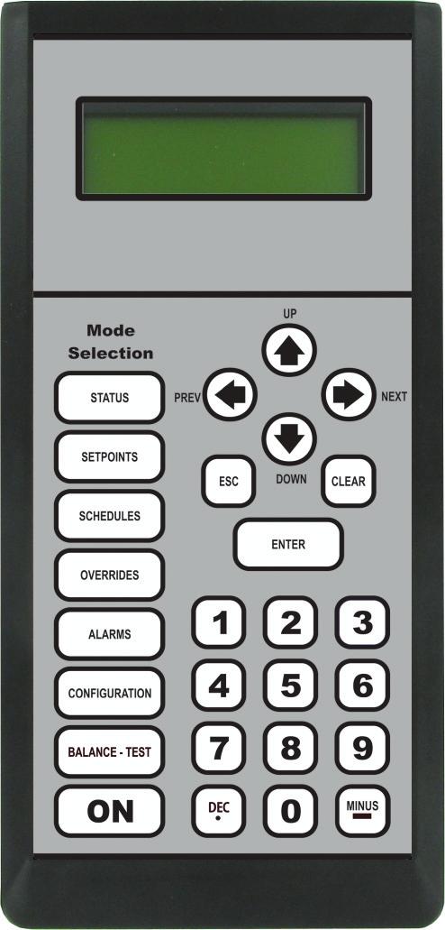
6 SYSTEM CONNECTION Modular System Manager SD Zone Zone Modular System Manager SD DEC 0 MINUS - PREV 9.00" ESC UP DOWN ENTER CLEAR NEXT STATUS SETPOINTS SCHEDULES OVERRIDES ALARMS 6.25" The OE Modular System Manager SD provides a direct link to enable you to view the status and adjust the setpoints of the VCCX2, VCC-X, VCB-X, VCM-X, VCM-X E-BUS, RNE, SA E-BUS, VCM, VAV/CAV, MUA II or VAV/Zone Controller on the control system communications loop. The System Manager SD is housed in a beige-colored plastic enclosure. The System Manager has a programmable 4 Gigabyte SD card and is equipped with a 4-line-by-20-character backlighted display panel and a 24-key membrane keypad for data selection and entry. All keypad operations are simple and straight forward, utilizing non-cryptic plain English language messages. Menu-driven programming allows for easy setup and operation without the need for specialized training. The System Manager also has 2 integral LEDs for user notification of system alarm conditions and override initiations. Protection from unauthorized users is provided by the System Manager s integral multi-level passcode authorization programming. 1.81" Figure 3: Modular System Manager SD Dimensions For a Stand-Alone system, a power/comm cable with modular connectors on one end and stripped wire ends on the other end is provided to facilitate connecting communications and power to the Modular System Manager from the 24 VAC power source and the HVAC unit controller communication wiring terminals. Alternatively, 2-conductor, twisted pair with shield cable can be used to wire from the RS-485 terminal block on the back of the Modular System Manager to the Controller s communicaton terminal. If this is an Interconnected System, all controllers that are interconnected with communications cable can be programmed from any controller on the loop. If this is a Networked System, all controllers on the entire Networked System can be programmed from one controller. The Modular System Manager is designed for wall mounting. Mounting holes are provided to attach the Modular System Manager to a standard handy box. It is recommended that the System Manager be mounted at approximately eye level to allow for ease of programming and reading of the display. The System Manager is typically mounted in the building manager s or superintendent s office or in an equipment room. The attractive enclosure is quite suitable for mounting in any location. 6
7 SYSTEM CONNECTION Modular System Manager SD Connection Stand Alone and Network Connection As previously described, when the System Manager is to be connected to a Stand Alone system, a 12-foot cable with modular connectors on one end and stripped wire ends on the other end is provided for this purpose. This is used to facilitate connecting communications and power wiring to the Modular System Manager from a 24 VAC power source and to the HVAC unit controller communication wiring terminals. If the supplied cable wire is not long enough for your installation, a standard modular cable of the correct length can be purchased through WattMaster and one of the modular connectors can be cut off to allow for the transformer and communication terminal wiring connections. It is recommended that you do not splice the communications wire if at all possible. The transformer should be rated at 6 VA minimum power output. Alternatively, 2-conductor, twisted pair with shield cable can be used to wire from the RS-485 terminal block on the back of the Modular System Manager to the Controller s communicaton terminal. All controllers on the entire Networked System can be programmed from one controller. See Figure 4 below for typical connection information. Controller Board T SHLD R 24VAC Transformer (By Others) Rated for 6 VA Modular System Manager SD Back View Line Voltage GND 24VAC Local Loop RS or 57,600 Baud All Comm Loop Wiring Is Straight Through T SH R T SH R T SH R T SH R 4GB NOTE: For Stand-Alone Installations (No CommLink or MiniLink), All TERM Jumpers Must Be ON. For All Applications With CommLink(s) Or MiniLink(s), All Jumpers Must Be OFF. Use Supplied Modular Cable With Stripped Ends For Connection To Terminal Block And Transformer WHITE (T) DRAIN WIRE (SHLD) BLACK (R) RED (24 VAC) BROWN (GND) GREEN (GND) T SHLD R Controller Board Class 2 Transformer Rated For 6 VA Minimum Figure 4: Modular System Manager SD Connection and Wiring Details 7
8 MODULAR SERVICE TOOL SD Modular Service Tool Keys Operator Interfaces In order to configure and program the VCCX2 Controller, you must have an Operator s Interface or a personal computer with the Prism 2 computer front-end software installed. Three different Operator Interfaces are available for programming of the VCCX2 Controls System the Modular Service Tool SD, the Modular System Manager SD, and/or the System Manager TS-L (Limited Access). These devices allow you to access the status and setpoints of any controller on your communications loop. This manual describes the Modular Service Tool SD. If using the System Manager TS-L, please see the System Manager TS-L Technical Guide. If using Prism 2, please see the Prism 2 Technical Guide. The Modular Service Tool and Modular System Manger SD allow you to view any input or output status and change any setpoint to fine-tune the operations of the total system. All keypad operations are simple and straightforward, utilizing non-cryptic plain English messages. Display Screens & Data Entry Keys See the chart below for a list of the keypad descriptions and functions. Keypad Description ESC ENTER Clear Minus DEC Function Use this key to exit from screens or from data entry or to return to the Main Screen from any screen in the system. Use this key to enter a new value. If a data entry mistake is made, press this key to clear the data entry field and start over. This key also turns off the power to the Service Tool when on the Main Screen If a setpoint with a negative value is required, press this key for the minus sign. Press this key when entering data that requires a decimal point. Use these keys to change values in the Configuration Screens as prompted. Use these keys to step backward or forward through the screens. Mode Selection Buttons The Modular Service Tool is provided with Mode Selection Buttons. These buttons give you instant access to the specific mode desired without having to scroll through several menu screens to get there. Button Description Table 2: Button Descriptions Function STATUS Pressing this button takes you directly to the controller Status screens. SETPOINTS Pressing this button takes you directly to the controller Setpoints screens. SCHEDULES Pressing this button takes you directly to the controller Schedules screens. OVERRIDES Pressing this button takes you directly to the controller Overrides screen. See the Override Button section on page 19 for a description of this function. See Note 1 below. ALARMS Pressing this button takes you directly to the controller Alarms screen. See the Alarms Button section on page 18 for a description of this function. CONFIGURATION Pressing this button takes you directly to the controller Configuration screens. BALANCE-TEST Pressing this button takes you directly to the controller Balance-Test screens. NOTE: (1) The Modular Service Tool will only search the Overrides one loop at a time. You must enter the Loop number and the MiniLink PD unit ID (60). Table 1: Keypad Descriptions 8
9 MODULAR SERVICE TOOL SD Initialization & Setting the Time & Date Modular Service Tool Initialization Modular Service Tool Initialization Screen and Setup Screens After connecting the Service Tool to the controller with the supplied cable, press <ON>. The Initialization Screen will appear followed by the Setup Screens as shown below. If there is no SD card installed, the second screen will display, No SD Card Connected! Powering Down! Initializing Service Tool vx.xx WattMaster Controls Although the times are displayed on the Main Screen in a standard 12-hour format, you must program them using the 24-hour military format. If you configured the VCCX2 Controller to use its own Internal Schedules, the Occupied/Unoccupied modes are calculated on the basis of the current real time clock reading. The two screens that follow will appear. To scroll through the fields, press <> or <ENTER>. In order to save a new value, you must press <ENTER>. Program Time/Date Day (Sunday=0): X Enter Hr. (0-23): XX Enter Minutes : XX 1) Set Time & Date 2) Communications NEXT) More Options ESC) Exit Menu 3) Energy Saving 4) Update Software NEXT) More Options ESC) Exit Menu NOTE: Once you press <ESC> while at the Setup Screens shown above, you can access them again by pressing <NEXT> or cycling power. Setting The Time & Date The Modular Service Tool is equipped with a real time clock chip allowing it to maintain the correct time. Once you have programmed the correct time and date, the information is broadcast globally to all controllers on the entire system. NOTE: If you are in a time zone that has daylight savings, you will need to manually adjust the time twice a year. Programming the Time From the Setup Screen shown below, press <1> on your keypad to access the Set Time & Date Screens. (You may have to press <NEXT> to access this screen). 1) Set Time & Date 2) Communications NEXT) More Options ESC) Exit Menu Day - Enter the Day of the Week (0 to 6) Sunday = 0 Hours (Hr) - Enter Hours in 24-Hour Military Format (1700 = 5:00 PM) Minutes - Enter the Minutes (0 to 59) Programming the Date To scroll through the fields, press <> or <ENTER>. In order to save a new value, you must press <ENTER>. Program Time/Date Month (1-12): XX Day (1-31): XX Year (00-99): XX Month - Enter the Month (1 to 12) Day - Enter the Day of the Month (1 to 31) Year - Enter the current Year with two digits (00 to 99) When you have finished programming the time and date, press <ESC> to return to the Setup Screen shown below. 1) Set Time & Date 2) Communications NEXT) More Options ESC) Exit Menu 9
10 MODULAR SERVICE TOOL SD Setting the Operating Mode and Energy Saving Timer Setting the Operating Mode The Operating Mode is displayed on the last line of the Main Screen as shown below. The factory default setting for the Service Tool is LS (Low Speed) Stand Alone Mode. LS Stand Alone Mode is the correct configuration for the VCCX2 Controller when in Stand Alone Mode. Service Tool SD vx.xx 01/16/17 02:21 PM LS Stand Alone No Communication If you are using this Service Tool on a communications loop and have an installed MiniLink PD or CommLink, you will need to change the setting to LS (Low Speed) Network Mode. If you are using a VCCX2 Controller that is set for high speed, you will need to change the setting to HS (High Speed) Stand Alone Mode or HS (High Speed) Network Mode. If your display indicates a different mode than the one you need, press <2> at the Setup Screen shown below. You may have to press <NEXT> to access this screen. 1) Set Time & Date 2) Communications NEXT) More Options ESC) Exit Menu The Communications Screen will appear as shown below. Stand Alone Mode Lo Speed Connection Use Left/Right Arrow To Change Selections Press <> or <> to select the proper mode of operation. When you have made your selection, press <ENTER>. The following screen will appear. You Have Changed The System Mode Press Any Key To Continue Setting the Energy Saving Timer The Modular Service Tool has a built-in timer that can be programmed to shut the Service Tool off after a specified period of time if no buttons are pressed. This is a very useful feature if you are powering the Service Tool from the internal batteries. To set the Energy Saving Timer, press <NEXT> at the first Setup Screen and <3> at the second Setup Screen shown below. (You may have to press <NEXT> to access these screens). 1) Set Time & Date 2) Communications NEXT) More Options ESC) Exit Menu 3) Energy Saving 4) Update Software NEXT) More Options ESC) Exit Menu The Energy Saving Screen will appear as shown below: Energy Saving Automatic Power Down Minutes: xx Press ESC to Exit Enter the number of minutes you want the Service Tool to stay active before it automatically powers down and press <ENTER>. To cancel the automatic power down, enter <99> and press <ENTER>. After you have entered a number between 1 and 99 minutes, press <ESC> to exit the screen. The Setup Screen will appear again as shown below: 1) Set Time & Date 2) Communications NEXT) More Options ESC) Exit Menu Press any key to continue. The Setup Screen will appear as shown below: 1) Set Time & Date 2) Communications NEXT) More Options ESC) Exit Menu 10
11 MODULAR SERVICE TOOL SD Alarm and Override Search Modular Service Tool Alarm Search NOTE: When you press the <ALARMS> button on the Modular Service Tool, it will search only the unit ID that you have entered; therefore, you must search each unit individually to access all alarms for that controller. To search for alarms, press < ALARMS> while on any screen but the Main Screen. The Unit Selection Screen will be displayed. Enter Unit Address Then Press Enter Selected Unit#: XXXX Enter the Unit ID of the controller the Service Tool is connected to and press <ENTER>. Once communication is established, the words Press Down will appear at the bottom of the screen. NOTE: If Press Down does not appear at the bottom of the screen, communication with the controller has not been established. One of the following screens will appear: VCCX2 NO ALARMS V.XXX Modular Service Tool Override Search When a space sensor with override option is used with any VAV/ Zone or Unit Controller, the Modular Service Tool can determine and report any controllers that are currently operating in an override condition on a specific Loop by entering a Loop ID number and then doing a search. NOTE: When you press the <OVERRIDES> button on the Modular Service Tool, it will search only the Loop number that you enter; therefore, you must search each loop individually to access all overrides. To access the Overrides Screen, press <OVERRIDES> from the Modular Service Tool s keypad. A screen will appear asking you to enter the unit ID. Enter Unit Address Then Press Enter Selected Unit#: XXXX Enter the Unit ID for the MiniLink PD (MLPD) of the loop you wish to search and press <ENTER>. The MLPD is always address 60 on each loop. So the unit ID of any particular MLPD would be the loop number followed by 60. In the example above, Loop 1, address 60 has been entered. Once communication is established, the words Press Down will appear at the bottom of the screen. NOTE: If Press Down does not appear at the bottom of the screen, communication with the controller has not been established. VCCX2 V.XXX If communications are successful, one of the following screens will appear: ALARMS PRESENT SCROLL DOWN TO VIEW VCCX2 V.XXX NO OVERRIDES Press <> to scroll through all the alarms for the controller that the Modular Service Tool is connected to. To clear any alarms that are found, you must fix the problem indicated in the alarm. Once the problem is fixed, the alarm will clear from the screen the next time the unit is polled. VCCX2 V.XXX OVERRIDES PRESENT SCROLL DOWN TO VIEW After the Service Tool completes its search, it will post a message to tell you if there are overrides present. If there are overrides, press <> and all units on the loop will be listed showing Override: Yes or No. Press <OVERRIDES> again to access overrides on a different loop. Enter the Unit ID of the MLPD of that loop. 11
12 MODULAR SERVICE TOOL SD Schedules and Holidays Scheduling You can access the Unit Controller Scheduling Screens by pressing <SCHEDULES>. The Unit Selection Screen will be displayed. Enter Unit Address Then Press Enter Selected Unit#: XXXX Enter the Unit ID of the controller the Service Tool is connected to and press <ENTER>. Once communication is established, the words Press Down will appear at the bottom of the screen. NOTE: If Press Down does not appear at the bottom of the screen, communication with the controller has not been established. Press the <> button and then press <ENTER> to access the scheduling function you wish to view. The screens will step through the Start Time and then the Stop Time for each day of the week. You can quit at any point in the process by pressing <ESC>. There are two Start/Stop events available per day, so the screen will show which event is being programmed. If you need only one event, keep Event #2 s times set at ZERO. All times are in 24-hour military format, so 5:00 PM would be entered as If both the Start and Stop Times are ZERO, the schedule is in a continuous OFF mode. (Also, use for Remote Forced Occupied applications using the Forced Occupied Binary Input.) If both the Start and Stop Times are 2359, the schedule is in a continuous ON mode. NOTE: The second line displays which day of the week is currently being programmed. The day of the week automatically increments as you exit the Event #2 screen for the day and continue to the next day s Event #1 screen. VCCX2 Schedule Menu Schedule Override Week Schedules Holidays CAUTION: The controller ships with all schedules set to zero so that the controller will not attempt to heat or cool before you have configured the system. Week Schedules Event #1 VCCX2 Schd ID # Sunday Event #1 Start Time: XXXX Stop Time: XXXX Event #2 VCCX2 Schd ID # Sunday Event #2 Start Time: XXXX Stop Time: XXXX If you are using the internal scheduling capability of the Unit Controller, set the schedule hours and holiday periods from the menu shown above. You can also force the unit to operate continuously in occupied or unoccupied mode by selecting the Schedule Override menu item and entering the desired command. If you are using an external contact closure to signal the occupied mode, you must access the Week Schedule Screens and set all start and stop times to zero to prevent the internal schedule from turning the equipment on when you don t want it to operate. Holiday Start/Stop Day Selection VCCX2 Schd ID # Holiday # 1 Start Mon/Day: XXXX [ July 4 th = 704 ] VCCX2 Schd ID # Holiday # 1 Stop Mon/Day: XXXX [ July 5 th = 705 ] The screens will step through the fourteen possible holidays, one period at a time. Line 2 shows which holiday is currently being programmed. Since a holiday period can encompass more than one day, you need to program the day the holiday starts and the day the holiday ends. If your holiday only lasts one day, simply set both the Start Day and the Stop Day to the same value. Remember to combine the month and day into a single four-digit value. EXAMPLE: 704 = July 4 th (NOTE: Leading zero not required) 1225 = December 25 th 12
13 MODULAR SERVICE TOOL SD Holiday Scheduling and Schedule Override Holiday Start/Stop Times Schedule Override VCCX2 Schd ID # Holiday Schedule Start Event #1: XXXX Stop Event #1: XXXX VCCX2 Ovrd ID # Schedule Override Enter Override: X [0=Auto 1=ON 2=OFF] VCCX2 Schd ID # Holiday Schedule Start Event #2: XXXX Stop Event #2: XXXX The fourteen holidays all use the same Start and Stop times which you program on this screen and the next. You must enter the time in 24-hour military format, the same as a regular week schedule. Normally, the holidays will operate in an unoccupied mode or a reduced schedule mode. There are two start/stop events available on holidays to match the standard schedule number of events. If you want to force the unit to operate in a continuous Occupied or Unoccupied mode, select this menu item to activate the desired method. If a Schedule Override is active, all other methods of schedule control are ignored (Push-Button, Internal, and Remote). As you can see on the last line of the display, enter <1> to run continuously in the Occupied Mode or <2> to run continuously in the Unoccupied Mode. To restore normal schedule operations, enter <0>. This override remains in effect until canceled and does not time-out like the Output Overrides do after 10 minutes of no communications. NOTE: Do not use the Force OFF mode in place of setting all the week schedules to ZERO if you are using a Remote Signal for your scheduling since the Override has priority over the Remote Signal. 13
14 MODULAR SYSTEM MANAGER SD System Manager SD Keys and Buttons Zone Zone Operator Interfaces In order to configure and program the Orion System controllers, you must have an Operator s Interface or a personal computer with the Prism 2 computer front-end software installed. Three different Operator Interfaces are available for programming of the Orion Controls System the Modular Service Tool SD, the Modular System Manager SD, and/or the System Manager TS-L (Limited Access). These devices allow you to access the status and setpoints of the controllers on your communications loop. This manual describes the Modular System Manager SD. If using the System Manager TS-L, please see the System Manager TS II Technical Guide. If using Prism 2, please see the Prism 2 Technical Guide. The Modular System Manager SD allows you to view any input or output status and change any setpoint to fine-tune the operations of the total system. All keypad operations are simple and straightforward, utilizing non-cryptic plain English messages. Display Screens & Data Entry Keys See the chart below for a list of the keypad descriptions and functions. Keypad Description ESC ENTER Clear Minus DEC Function Use this key to exit from screens or from data entry or to return to the Main Screen from any screen in the system. Use this key to enter a new value. If a data entry mistake is made, press this key to clear the data entry field and start over. If a setpoint with a negative value is required, press this key for the minus sign. Press this key when entering data that requires a decimal point. Use these keys to change values in the Configuration Screens as prompted. Use these keys to step backward or forward through the screens. Mode Selection Buttons The Modular System Manager is provided with Mode Selection Buttons. These buttons give you instant access to the specific mode desired without having to scroll through several menu screens to get there. Button Description STATUS SETPOINTS Function Pressing this button takes you directly to the controller Status screens. Pressing this button takes you directly to the controller Setpoints screens and Configuration menu. SCHEDULES Pressing this button takes you directly to the controller Schedules screens. OVERRIDES Pressing this button takes you directly to the controller Overrides screen. See the Override Button section on page 19 for a description of this function. See Notes 1 & 2 below. ALARMS Pressing this button takes you directly to the controller Alarms screen. See the Alarms Button section on page 18 for a description of this function. See Notes 1 & 2 below. NOTES: (1) This button only functions when the system is configured for Network Mode or Multiple MGRS Mode. It will not function in Stand Alone Mode. (2) The Search for Units function must be performed on the System Manager upon initial system setup before this function will be available. See the Network Mode & Multiple Managers Loop Search on page 20 of this manual for complete instructions on performing a loop search. Table 4: Button Descriptions Table 3: Keypad Descriptions 14
15 MODULAR SYSTEM MANAGER SD Initialization & Setting the Time & Date System Manager SD Initialization System Manager SD Initialization Screen and Setup Screens After connecting the System Manager to the controller with the supplied cable, press <ON>. The Initialization Screen will appear followed by the Setup Screens as shown below. If there is no SD card installed, the second screen will display, No SD Card Connected! Powering Down! NOTE: After exiting these screens, you can access them again by pressing <ESC> and then <> or by cycling power. INITIALIZING System Manager SD vx.xx WattMaster Controls 1) Set Time & Date 2) Communications NEXT) More Options ESC) Exit Menu 3) Change Passcodes 4) Loop Search NEXT) More Options ESC) Exit Menu 5) Alarm Search NEXT) More Options ESC) Exit Menu Programming the Time From the Setup Screen shown below, press <1> on your keypad to access the Set Time & Date Screens. 1) Set Time & Date 2) Communications NEXT) More Options ESC) Exit Menu Although the times are displayed on the Main Screen in a standard 12-hour format, you must program them using the 24-hour military format. If you configured the Unit Controller to use its own Internal Schedules, the Occupied/Unoccupied modes are calculated on the basis of the current real time clock reading. The two screens that follow will appear. To scroll through the fields, press <> or <ENTER>. In order to save a new value, you must press <ENTER>. Program Time/Date Day (Sunday=0): X Enter Hr. (0-23): XX Enter Minutes : XX Day - Enter the Day of the Week (0 to 6) Sunday = 0 Hours (Hr) - Enter the Hour (0-23) in 24-Hour Military Format (13 = 1:00 PM) Minutes - Enter the Minutes (0 to 59) Programming the Date To scroll through the fields, press <> or <ENTER>. In order to save a new value, you must press <ENTER>. Setting The Time & Date The System Manager SD is equipped with a real time clock chip allowing it to maintain the correct time. Once you have programmed the correct time and date, the information is broadcast globally to all controllers on the entire system. NOTE: A Level 1 or Level 2 User can set the time and date. NOTE: If you are in a time zone that has daylight savings, you will need to manually adjust the time twice a year. Program Time/Date Month (1-12): XX Day (1-31): XX Year (0-99): XX Month - Enter the Month (1 to 12) Day - Enter the Day of the Month (1 to 31) Year - Enter the current Year (0 to 99) When you have finished programming the time and date, press <ESC> to return to the Setup Screen. 15
16 MODULAR SYSTEM MANAGER SD Setting the Operating Mode Zone Zone Setting the Operating Mode The Operating Mode is displayed on the last line of the Main Screen as shown below. The factory default setting for the System Manager is LS (Low Speed) Stand Alone Mode. System Manager SD 01/16/17 02:21 PM LS Stand Alone The Passcode Clearance Screen will appear as shown below. THIS ACTION REQUIRES A SPECIAL HIGH LEVEL PASSCODE CLEARANCE Enter: XXXXXXX Enter the seven digit passcode < > to access the next screen. You will then see the screen below displayed. The System Manager must be configured for the correct mode of operation for your system. There are 5 modes of operation available for the Orion System LS (Low Speed) Stand-Alone, HS (High Speed) Stand-Alone, LS (Low Speed) Network, HS (High Speed) Network, and LS (Low Speed) & HS (High Speed) Multiple MGRS. If you are using this System Manager on a communications loop that doesn t have a MiniLink PD or CommLink connected to it and you have a single System Manager on your system, then you need to operate in LS (Low Speed) Stand-Alone Mode. If you are using a VCCX2 Controller or GPC-XP Controller that is set for high speed, and you don t have a MiniLink PD or CommLink connected to the loop, then you will need to change the setting to HS (High Speed) Stand Alone Mode. If you are using the System Manager on a communications loop and have an installed MiniLink PD or CommLink, you will need to change the setting to LS (Low Speed) Network Mode. If you are using a VCCX2 Controller or GPC-XP Controller that is set for high speed, and are using a MiniLink PD or CommLink, then you will need to change the setting to HS (High Speed) Network Mode. If you are using this System Manager on a communications loop, have a MiniLink PD or CommLink installed, and have multiple System Managers, then you need to operate in Multiple MGRS Mode. If your display indicates a different mode than the one you need, press <2> at the Setup Screen shown below. You will have to cycle power to get to this screen or by pressing <ESC> and <PREV>. 1) Set Time & Date 2) Communications NEXT) More Options ESC) Exit Menu Stand Alone Mode Lo Speed Connection Use Left/Right Arrow To Change Selections Press <> or <> if you need to change the mode of operation to LS (Low Speed) Stand-Alone, HS (High Speed Stand- Alone, LS (Low Speed) Network, HS (High Speed Network, LS (Low Speed) Multiple Manager or HS (High Speed) Multiple Manager and then press <ENTER> to save your selection. If you are not using Multiple Manager Mode, press <ESC> at the screen below and continue scrolling right and left. Multiple Manager Unit Address: 0 Press ESC to Exit For Multiple MGRS Mode, enter the address at which you want this particular System Manager to be set. When multiple System Managers are used on a local loop, each must be set with a unique address different from any other device on that loop. You must perform this same operation again for each System Manager installed. If you want one of these System Managers to be able to indicate alarms and overrides for the entire system, you must select either LS or HS Network Mode on that particular System Manager. Once you have the correct number per the display above displayed, press <ENTER>. The following screen will appear telling you that you have changed the system mode: You Have Changed The System Manager Mode Press Any Key To Continue Press any key on the keyboard to exit this screen. 16
17 MODULAR SYSTEM MANAGER SD Changing Passcodes System Manager Passcodes Changing the mode of operation, updating software, changing schedules, and changing setpoints and configurations require passcode clearance. The screen below will appear if this action requires passcode clearance. THIS ACTION REQUIRES PASSCODE CLEARANCE Enter Passcode: XXXX The System Manager has three levels of user access. All users can view Status Screens. Level 1 users are limited to changing the Time and Date and Operating Schedules. Level 2 users have complete system access. Any status or setpoint field can be read or reset from the System Manager. Passcodes can only be changed by a Level 2 user. Enter the passcode and press <ENTER>. The following screen will appear: Enter New Passcode Level 1...: XXXX Level 2...: XXXX [Must Be 4 Digits] This screen allows you to enter new Level 1 and/or Level 2 passcodes. Passcodes must always be four digits in length, so the usable range of numbers is 1000 to CAUTION: If you change the Level 2 passcode and cannot remember what it is, you will be locked out of your system! These two levels of passcodes are programmable by any Level 2 user. The default Level 1 passcode is 1111 and the default Level 2 passcode is If you wish to change either Level 1 or Level 2 passcodes, please see the instructions that follow. From the Main Status Screen, press <ESC> and then press <PREV>. The following screen will appear: 1) Set Time & Date 2) Communications NEXT) More Options ESC) Exit Menu Press <> for the Next Menu. The following screen will be displayed: 3) Change Passcodes 4) Loop Search NEXT) More Options ESC) Exit Menu Press <3> for Change Passcodes. The following screen will be displayed: THIS ACTION REQUIRES PASSCODE CLEARANCE Enter Passcode: XXXX 17
18 MODULAR SYSTEM MANAGER SD Loop Search and System Alarm Search Zone Zone Network Mode & Multiple Managers Loop Search When the System Manager is configured for Network Mode, a loop search must initially be performed for the System Manager to recognize alarms or overrides. Also, when you have a system that has multiple System Managers and you have one of the System Managers set to (63) Network Mode for alarm and override indication, you must also perform a loop search for that System Manager. This allows the System Manager to be aware of all alarms and overrides for all local loops on the entire system. To access the Loop Search Screen, from the Setup Screen, press <ESC> and then press <PREV>. 1) Set Time & Date 2) Communications NEXT) More Options ESC) Exit Menu Press <> for Next Menu. The following screen will be displayed: 3) Change Passcodes 4) Loop Search NEXT) More Options ESC) Exit Menu Press <4> for Loop Search. The following screen will be displayed: Loop Search Current Loop = XX Loops Found = XX Searching The System Manager will now proceed to search all loops to find the MiniLink PDs that are connected to the system. The screen will display the current loop being searched and the number of loops currently found. Once the search is completed, the following screen will be displayed: Loop Search Finished Loops Found = XX Press ESC to Exit The screen will display the number of loops found on your system. The information will be saved into the System Manager s memory. No further loop searches will be required unless you add an additional MiniLink PD to the Network System. System Alarm Search The System Manager can be used to search for all active alarms on the system. You must configure the MiniLink PD to allow for Alarm Polling for each controller you want polled for alarms. See the MiniLink PD programming section on page 87 of this manual for setting information. This option will alert you of the number of alarms present on individual units, but will not tell you what type of alarm are present. You will have to perform and individual unit alarm search for detailed alarm information. To access the Alarm Search Screen, from the Setup Screen, press <ESC> and then press <PREV>.. 1) Set Time & Date 2) Communications NEXT) More Options ESC) Exit Menu Press <> for Next Menu. The following screen will be displayed: 3) Change Passcodes 4) Loop Search NEXT) More Options ESC) Exit Menu Press <> for Next Menu. The following screen will be displayed: 5) Alarm Search NEXT) More Options ESC) Exit Menu Press <5> for Alarm Search. The entire system is searched from this point. The following screen will be displayed: Alarm Screen SEARCHING! Once the Alarm Search is complete, one of the following screens will display: Alarm Screen XX ALARMS ON UNIT XX 18
19 MODULAR SYSTEM MANAGER SD Unit Alarm Search and Override Search Alarm Screen System Manager Override Search NO ALARMS DETECTED NOTE: In order for the Override Search to work, a Loop Search must be performed first. See page 18 for details. To check controllers individually for alarms, use the <ALARMS> button on the Main Display. Unit Alarm Search The System Manager can be used to search for all active alarms one controller at a time. Press <ALARMS>. The Unit Selection Screen below will be displayed. Enter Unit Address Then Press Enter Selected Unit#: XXXX Enter the Unit ID of the controller you wish to search and press <ENTER>. Once communication is established, the words Press Down will appear at the bottom of the screen. NOTE: If Press Down does not appear at the bottom of the screen, communication with the controller has not been established. The following screen will appear. The System Manager will search for any active alarms on the unit and one of the following screens will appear: When a space sensor with override option is used with any VAV/Zone Controller or Unit Controller, the System Manager can determine and report any controllers that are currently operating in an override condition. This function requires that a MiniLink PD is installed on each loop where the controllers may be located. The MiniLink PD must be configured to allow for Alarm Polling for each controller that Override Polling Enabled is desired for this function to work. See the MiniLink PD programming section on page 87 of this manual for setting information. To access the Space Sensor Overrides Screen, press <OVER- RIDES>, The following screen will appear. Overrides Screen SEARCHING! After the System Manager completes its search, it will list the first unit on the system that is currently in the override mode. Press the <> button to scroll through all units that are in the Override Mode. Overrides Screen Loop = 1 Unit = 59 OVERRIDE FOUND CONTROLLER V.XXX NO ALARMS CONTROLLER V.XXX ALARMS PRESENT SCROLL DOWN TO VIEW Press <> to scroll through all the alarms for the controller that the Modular Service Tool is connected to. To clear any alarms that are found, you must fix the problem indicated in the alarm. Once the problem is fixed, the alarm will clear from the screen the next time the unit is polled. 19
20 MODULAR SYSTEM MANAGER SD Schedules and Holidays Zone Zone Scheduling You can access the Controller Scheduling Screens by pressing <SCHEDULES>. The screen below will appear because Scheduling requires passcode clearance. A Level 1 or 2 passcode can change schedules. THIS ACTION REQUIRES PASSCODE CLEARANCE Enter Passcode: XXXX Week Schedules From the Unit Schedule Menu, select Week Schedules. The following two screens will appear in order: Event #1 Schd Sunday Event #1 Start Time..: XXXX Stop Time...: XXXX If the correct passcode was entered, the Unit Selection Screen will be displayed. Enter Unit Address Then Press Enter Selected Unit#: XXXX Event #2 Schd Sunday Event #2 Start Time..: XXXX Stop Time...: XXXX Enter the Unit ID of the controller you wish to search and press <ENTER>. Once communication is established, the words Press Down will appear at the bottom of the screen. NOTE: If Press Down does not appear at the bottom of the screen, communication with the controller has not been established. The Unit Schedule Menu will be displayed. Schedule Menu Schedule Override Week Schedules Holiday Schedules Press the <> button until the cursor is on the desired option and then press <ENTER>. If you are using the internal scheduling capability of the Controller, set the schedule hours and holiday periods from the menu shown above. You can also force the unit to operate continuously in occupied or unoccupied mode by selecting the Schedule Override menu item and entering the desired command. If you are using an external contact closure to signal the occupied mode, you must access the Week Schedule Screens and set all start and stop times to zero to prevent the internal schedule from turning the equipment on when you don t want it to operate. The screens will step through the Start Time and then the Stop Time for each day of the week. You can quit at any point in the process by pressing <ESC>. There are two Start/Stop events available per day, so the screen will show which event is being programmed. If you need only one event, keep Event #2 s times set at ZERO. All times are in 24-hour military format, so 5:00 PM would be entered as If both the Start and Stop Times are ZERO, the schedule is in a continuous OFF mode. (Use for Remote Signal Contact.) If both the Start and Stop Times are 2359, the schedule is in a continuous ON mode. NOTE: The second line displays which day of the week is currently being programmed. The day of the week automatically increments as you exit the Event #2 screen for the day and continue to the next day s Event #1 screen. CAUTION: The controller ships with all schedules set to zero so that the controller will not attempt to heat or cool before you have configured the system. 20
21 MODULAR SYSTEM MANAGER SD Holiday Scheduling and Schedule Override Holiday Start/Stop Day Selection From the Unit Schedule Menu, select Holiday Schedules. The following four screens will appear in order: Schedule Override From the Unit Schedule Menu, select Schedule Override. The following screen will appear: Hldy Holiday # 1 Start Mon/Day.: XXXX [ July 4 th = 704 ] Ovrd Schedule Override Enter Override...: X [0=Auto 1=ON 2=OFF] Hldy Holiday # 1 Stop Mon/Day.: XXXX [ July 5 th = 705 ] The screens will step through the fourteen possible holidays, one period at a time. Line 2 shows which holiday is currently being programmed. Since a holiday period can encompass more than one day, you need to program the day the holiday starts and the day the holiday ends. If your holiday only lasts one day, simply set both the Start Day and the Stop Day to the same value. Remember to combine the month and day into a single four-digit value. EXAMPLE: 704 = July 4 th (NOTE: Leading zero not required) 1225 = December 25 th If you want to force the unit to operate in a continuous Occupied or Unoccupied mode, select this menu item to activate the desired method. If a Schedule Override is active, all other methods of schedule control are ignored (Push-Button, Internal, and Remote). As you can see on the last line of the display, enter <1> to run continuously in the Occupied Mode or <2> to run continuously in the Unoccupied Mode. To restore normal schedule operations, enter <0>. This override remains in effect until canceled and does not time-out like the Output Overrides do after 10 minutes of no communications. NOTE: Do not use the Force OFF mode in place of setting all the week schedules to ZERO if you are using a Remote Signal for your scheduling since the Override has priority over the Remote Signal. Holiday Start/Stop Times Hldy Holiday Schedule Start Event #1: XXXX Stop Event #1: XXXX Hldy Holiday Schedule Start Event #2: XXXX Stop Event #2: XXXX The fourteen holidays all use the same Start and Stop times which you program on this screen and the next. You must enter the time in 24-hour military format, the same as a regular week schedule. Normally, the holidays will operate in an unoccupied mode or a reduced schedule mode. There are two start/stop events available on holidays to match the standard schedule number of events. 21
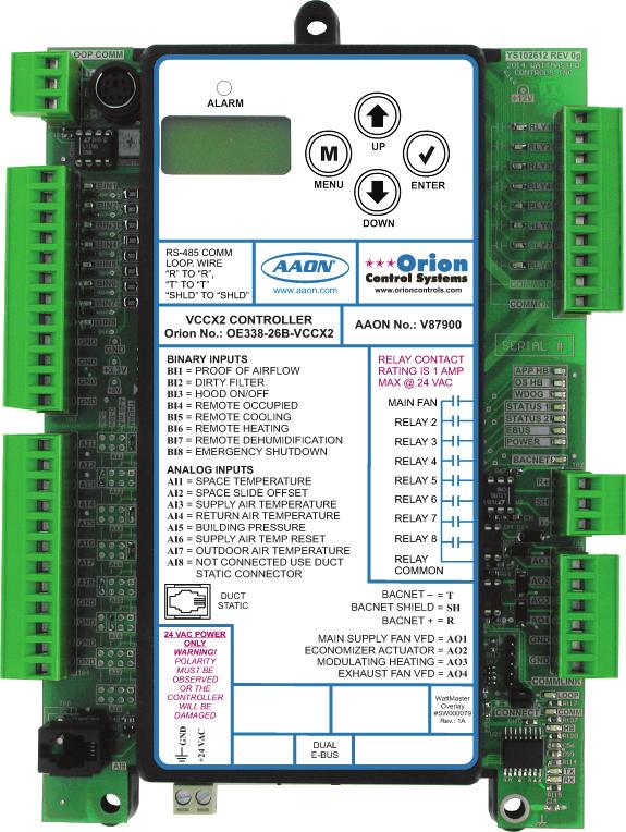
22 VCCX2 CONFIGURATION VCCX2 Configuration Screen Index Zone Zone VCCX2 Configuration Screen Index The available Configuration Screens for the VCCX2 Controller are listed on the next few pages by sequential screen number. When each VCCX2 Controller is configured for the first time, it is best to start with screen #1 and proceed to each screen in numerical order until you have viewed all available Configuration Screens. This ensures that you have seen all the available VCCX2 Controller configuration possibilities and have the opportunity to change or accept the defaults for each screen. Once the unit is configured and you decide to change one of the screen options, it is helpful to know what screen number contains the configuration you wish to change. With this in mind, the following is a list of all the VCCX2 Configuration Screens in numerical order with a brief listing of the configuration feature available on each screen. 22 Screen #1 Screen #2 Screen #3 Screen #4 Screen #5 Screen #6 Screen #7 Screen #8 Screen #9 Screen #10 Screen #11 Screen #12 Screen #13 Screen #14 Screen #15 Screen #16 Screen #17 Screen #18 Screen #19 Screen #20 Screen #21 Screen #22 Screen #23 Screen #24 Screen #25 Screen #26 Screen #27 Screen #28 Screen #29 Screen #30 Screen #31 Screen #32 Screen #33 Screen #34 Sensor Scaling (Fahrenheit / Celsius) RSM 1 & RSM 2 Installed RSM 3 & RSM 4 Installed RSMSD Installed & RSM Type EM1 Expansion Module Installed & 12 Relay E-BUS Expansion Module MHGRV-X & Expansion Module Installed MODGAS-X & XWR #2 Installed Preheat-X Controller Installed HVAC Mode Enable Source HVAC Mode Set By Remote Contact SAT Reset Source Reset Rate Interval Space Sensor Type Remote Space Sensor Board Address Outdoor Sensor Type Return Sensor Type Static Pressure Control Static/Fan Control Rate Static Pressure Control Max Adjust Fan Voltage Output - Min/Max Supply Fan Cycle Mode Fan Proving Fan Starting Delay Purge Mode Delay Heat Type Modulating Heat Output Signal - Min/Max Cool Type Mech Heat/Cool Alarm Delay Economizer Control Type Title 24 Economizer Economizer in Unoccupied Mode Economizer Enable Source Economizer Control Loop Rate/Proportional Window Economizer Voltage Output - Min/Max Screen #35 CO 2 Sensor Installed Screen #36 Building Pressure Sensor Installed Screen #37 Building Pressure Control Screen #38 Building Pressure Control Rate Screen #39 Building Pressure Control Max Adjust Screen #40 Exhaust Fan Output Screen #41 Heat Pump Configuration Screen #42 WSHP Glycol Percentage Screen #43 Aux Heat Type Screen #44 Dehumidification Control Screen #45 Humidity Control E-BUS Sensor Type Screen #46 Reheat Control Screen #47 Type of Airflow Station Screen #48 Monitor Outdoor Air Airflow Screen #49 Control Outdoor Air Airflow Screen #50 Outdoor Airflow Duct Size Screen #51 Monitor Supply Air Airflow Screen #52 Supply Airflow Duct Size Screen #53 Monitor Return Air Airflow Screen #54 Return Airflow Duct Size Screen #55 Monitor Exhaust Airflow Screen #56 Exhaust Airflow Duct Size Screen #57 Morning Warm Up Type Screen #58 AHU Uses Schedule Number Screen #59 Daylight Adjustment Start/Stop Date Screen #60 Trend Log Rate Screen #61 Emergency Shutdown Screen #62 Dirty Filter Screen #63 Broadcast Outdoor Air Temperature Screen #64 Broadcast Outdoor RH Screen #65 Broadcast Space Temperature Screen #66 Broadcast Space Humidity Screen #67 Broadcast CO 2 Screen #68 Broadcast Building Pressure Screen #69 Broadcast to Boxes Screen #70 Cool Stage Up and Down Delays Screen #71 Cool Stage Min Run and Min Off Delays Screen #72 Heat Stage Up and Down Delays Screen #73 Heat Stage Min Run and Min Off Delays Screen #74 Heat Pump Delays Screen #75 Heat/Cool Changeover Delay Screen #76 Return Air Bypass Control Screen #77 Morning Cool Down Type Screen #78 Evaporator Condenser Control Screens #79-85 VCCX2 Relays 1-8 Configuration Screens Screens #86-90 EM1 Relays 1-5 Configuration Screens Screens # Relay Configuration Screens
23 VCCX2 CONFIGURATION VCCX2 Configuration Screens Configuration Screens In order to correctly set up the VCCX2 Controller, you must first configure several parameters in regard to the type of HVAC unit and system you have installed. Most of these values and operating parameters are only set once at the initial system setup and are never changed. Modular Service Tool Instructions No matter what screen or menu you re in, press <CONFIGURA- TION>. The Unit Selection Screen will appear, shown below, requesting that you enter the unit ID number. Enter Unit Address Then Press Enter Selected Unit#: XXXX <ENTER>. Once communication is established, the words Press Down will appear at the bottom of the screen. NOTE: If Press Down does not appear at the bottom of the screen, communication with the controller has not been established. The following screen will be displayed: Change Setpoints Configure Unit Save/Copy/Restore VCCX2 CONFIGURATION RSM CONFIGURATION Select & Press Enter VCCX2 CONFIGURATION RSM CONFIGURATION Select & Press Enter Enter the Unit ID of the controller you wish to search and press <ENTER>. Once communication is established, the words Press Down will appear at the bottom of the screen. Then press <>. Select VCCX2 Configuration and then press <ENTER>. Press <ENTER> to save entered data and press <> to scroll through the screens. NOTE: If Press Down does not appear at the bottom of the screen, communication with the controller has not been established. System Manager SD Instructions From any Main screen, press <SETPOINTS>. The screen below will appear because this option requires passcode clearance. Only a Level 2 passcode can change setpoints. THIS ACTION REQUIRES PASSCODE CLEARANCE Enter Passcode: XXXX If the correct passcode was entered, the Unit Selection Screen will be displayed. Enter Unit Address Then Press Enter Selected Unit#: XXXX On the first screen, scroll down to the Configure Unit option and press <ENTER>. On the second screen, select VCCX2 Configuration and then press <ENTER>. This will take you to the first Configuration Screen shown below. Configuration Screen #1 - Sensor Scaling Sensor Scaling Fahrenheit Options are Fahrenheit or Celsius. If you make a change to this screen, after you press <ENTER> to have the system accept the change, you must return to the Unit Selection Screen to re-establish communications with the Controller. Default is Fahrenheit. Configuration Screen #2 - RSM #1 & #2 Module Installed RSM#1 Installed: NO RSM#2 Installed: NO If you have a one RSM Module installed, the 1st configuration option should be configured as YES. If you have a 2nd RSM Module installed, the 2nd configuration option should be configured as YES. Default is NO. Enter the Unit ID of the controller you wish to search and press 23
24 VCCX2 CONFIGURATION VCCX2 Configuration Screens Zone Zone Configuration Screen #3 - RSM #3 & #4 Modules Installed 24 RSM#3 Installed: NO RSM#4 Installed: NO If you have a 3rd RSM Module installed, the 1st configuration option should be configured as YES. If you have a 4th RSM Module installed, the 2nd configuration option should be configured as YES. Default is NO. Configuration Screen #4 - RSMSD Module Installed & RSM Type RSMSD Installed: NO RSM Type: VFD If you have a RSM-Single Digital installed (future), select YES. Default is NO. If you have RSM Module(s) installed, select the type of module - VFD or Digital. Default is VFD. Configuration Screen #5 - EM1 Expansion Module & E-BUS 12 Relay Module Installed EM1 Installed: NO 12RLY Installed: NO If you have Expansion Module EM1 installed, this configuration option should be configured as YES. Default is NO. If your unit utilizes the following, an EM1 Module is required: Modulating Chilled Water Return Air Bypass Control Title 24 Economizer Actuator Feedback If you have a 12 Relay E-BUS Expansion Module installed, the 2 nd configuration option should be configured as YES. Default is NO. Configuration Screen #6 - MHGRV-X & Reheat Expansion Module Installed MHGRV Installed: NO EXP Installed: NO If you have an MHGRV-X Controller installed, the 1 st configuration option should be configured as YES. If you also have a MHGRV-X Expansion Module installed, the 2 nd configuration option should be configured as YES. Defaults are NO. Configuration Screen #7 - MODGAS-X & MODGAS-XWR#2 Installed MODGS Installed: NO XWR#2 Installed: NO If you have a MODGAS-X or MODGAS-XWR Controller installed, the 1 st configuration option should be configured as YES. If using a second MODGAS-XWR Controller, the 2 nd configuration option should be configured as YES. Defaults are NO. Configuration Screen #8 - PREHEAT-X Controller Installed Preheat-X Installed: NO If you have a PREHEAT-X Controller installed, this configuration option should be configured as YES. Default is NO. Configuration Screen #9 - HVAC Mode Enable Source HVAC Source Supply Air This selects which sensor will determine the mode of operation of the unit and how it will operate. Default is Supply Air. Available options are: Supply Air This is for a standard Cooling Only VAV unit with optional Morning Warm Up. In the Occupied Mode, the unit will be in the Cooling Mode controlling to the Cooling Supply Air Setpoint. Supply Air/Tempering This selection is for VAV cooling only applications where because of cold outdoor temperatures, heat may need to be added in order to maintain the Cooling Supply Air Setpoint. This application requires Outdoor Air Enable Setpoints to be configured in order to initiate Cooling and Heating Modes. The Heating Supply Air Setpoint should be set at least 2 F below the Cooling Supply Air Setpoint. See the Sequence of Operations for details. Outdoor Air This is for a 100% OA Unit (MUA) using the OA Temperature Sensor to determine the Heating,
25 VCCX2 CONFIGURATION VCCX2 Configuration Screens Cooling, and Vent Modes of operation. Dehumidification utilizes an Outdoor Air Dewpoint Setpoint. Also use this configuration if the next screen will be configured for Modes Set By Remote Contact. Return Air Optional recirculating unit configuration using the Return Temperature Sensor to determine the Heating, Cooling, and Vent Modes of operation. Space Temperature Typical recirculating unit using a Space Temperature Sensor to determine the Heating, Cooling, and Vent Modes of operation. Space Temperature with High % OA If it is preferable to use Space conditions (instead of Outside Air) to control a 100% or high percentage outdoor air unit, this option allows tempering of the outdoor air in the Space Vent Mode of operation to prevent dumping of hot or cold air into the space. See the Sequence of Operations for details. NOTE: If this option is selected, the Economizer must be set to Standard Economizer. Single Zone VAV Recirculating unit using the Space Temperature Sensor to determine the mode of operation. Heating and Cooling are controlled to a Leaving Air Setpoint. Space Temperature resets the Supply Fan VFD speed to maintain the Space Temperature. Modulating Heating and Cooling must be used for this operation. Can be configured for CAV Heating using staged Heat. Configuration Screen #10 - HVAC Mode Set By Remote Contact HVAC Mode Set By Remote Contact: NO This option allows separate 24 VAC wet contact closures on the VCCX2 to force the unit into Heating, Cooling, and Dehumidification modes. If this option is selected, it applies to all three modes, and all three modes will only be initiated by these contact closures. If this is configured for YES, set the previous screen to Outdoor Air. See the VCCX2 Remote Contact Control section of the Sequence of Operations in the VCCX2 Controller Technical Guide for more details. Default is NO. Configuration Screen #11 - SAT Reset Source SAT Reset Source No Reset This configuration option is not available if Single Zone VAV was selected as the HVAC source. The Supply Air Setpoint can be automatically adjusted based on a selected reset source. This screen allows you to choose this source. Default is No Reset. The available selections are as follows: No Reset No SAT Setpoint Reset will occur. The SAT Setpoints remain fixed. Space Temperature The SAT Setpoints will be adjusted based on the Space Temperature. Outdoor Temperature The SAT Setpoints will be adjusted based on the Outdoor Air Temperature. Return Air Temperature The SAT Setpoints will be adjusted based on the Return Air Temperature. Fan VFD Signal The SAT Setpoints will be adjusted based on the VFD Signal. This is good for Adjusting the Setpoints based on the building s load by looking at the VFD speed. Remote Voltage The SAT Setpoints will be adjusted based on the Remote Supply Air Temperature Voltage Reset Signal. If the HVAC Source was set Single Zone VAV in Confi guration Screen #9, then line 3 on this screen will read No SAT Rst Allowed and the line 4 will be blank. Configuration Screen #12 - Reset Rate Interval Reset Interval Rate...: 30 s [1-255 Seconds] If you selected a Reset Source in Confi guration Screen #11, enter a value in seconds between This value determines how fast the Supply Air Temperature Setpoint is adjusted as the Reset Source changes. Default is 30 seconds. Configuration Screen #13 - Space Sensor Type Space Sensor Type None Default is None. If this unit has a Space Sensor installed, select from the following: Analog Wired Thermistor temperature sensor. E-bus Temp/RH Combination communicating temperature and humidity sensor. Receive Broadcast Space Sensor is attached to a separate device that will broadcast the reading, e.g., GPC-XP Controller. Remote Sensor Sensor is connected to a separate Unit Controller on the same loop (sharing a sensor). You can select the Unit Controller that will have the Remote Space Sensor on Confi guration Screen #14. Use BACnet Temp/RH If the BACnet front end will be writing the Space Temperature and Humidity values to the VCCX2 Controller, select this option. 25
26 VCCX2 CONFIGURATION VCCX2 Configuration Screens Zone Zone Configuration Screen #14 - Remote Space Sensor Board Address Remote Space Sensor Board Address: 0 If using a Remote Space Sensor (must be chosen in Confi guration Screen #13), enter the address of the board it is located on. This Unit Controller has to be on the same loop as the Controller that will be sharing the sensor. Configuration Screen #15 - Outdoor Sensor Type Outdoor Sensor Type None Default is None. If this unit has an Outdoor Air Sensor installed, select from the following: Analog Wired Thermistor temperature sensor. E-bus OAT/RH Combination communicating temperature and humidity sensor. Receive Broadcast Outdoor Sensor is attached to a separate device that will broadcast the reading, e.g., GPC-XP Controller. Use BACnet OAT/RH If the BACnet front end will be writing the Outdoor Air Temperature and Humidity values to the VCCX2 Controller, select this option. Configuration Screen #16 - Return Sensor Type Return Sensor Type None If this unit has a Return Air Sensor installed, select Analog if it is a wired Thermistor temperature sensor. Select E-bus Temp/RH if it is a combination communicating temperature and humidity sensor. Default is None. Configuration Screen #17 - Static Pressure Control Static Pr Control Fan VFD / SZ VAV Select what type of Duct Static Pressure is being controlled, if any. Default is Fan VFD/SZ VAV. The options are: None This unit is not controlling Duct Static Pressure. Fan VFD / SZ VAV This unit has a Supply Fan VFD that modulates to control the Duct Static Pressure or this is a Single Zone VAV application. Bypass Damper This unit uses a Bypass Damper to control the Duct Static Pressure. Configuration Screen #18 - Static/Fan Control Rate Static/Fan Control Rate: 10s [ 1-30 Seconds ] This value determines the time interval between changes to the Supply Fan Speed or the Bypass Damper Position during Duct Static Pressure Control. It also determines the time interval between changes to the Fan Speed during Single Zone VAV Reset of the Supply Fan VFD Speed. Default is 10 seconds. Configuration Screen #19 - Static Pressure Control Rate Max Adjust Static Pr. Control Max Adjust: 5% [ 1-30% ] This is the maximum amount that the Static Pressure Control output can adjust to when it needs to. Default is 5 percent. Configuration Screen #20 - Fan Voltage Output Fan Voltage Output Min Volts: 0.0VDC Max Volts: 10.0VDC Enter a value between 0.0 and 10.0 VDC for the main fan s minimum and maximum output voltage. The Duct Static Pressure Output Status Screen will display 0% to 100%, but the output will range from the minimum value set on this screen to the maximum value set on this screen. The VCCX2 will reverse the logic of the output signal when a Zoning Bypass Damper is used. Defaults are 0 VDC Min and 10 VDC Max. Minimum Fan Voltage Maximum Fan Voltage
27 VCCX2 CONFIGURATION VCCX2 Configuration Screens Configuration Screen #21 - Fan Cycle Mode Configuration Screen #24 - Purge Mode Delay Fan Cycle Mode NO Select YES if you want the HVAC unit s Supply Fan to only run during Heating or Cooling Mode. If you want the HVAC unit s Supply Fan to run continuously while in the Occupied Mode, regardless of the Heating or Cooling Mode, select NO. Default is NO. Configuration Screen #22 - Fan Proving Fan Proving NO Select YES if the unit is equipped with a Proof of Flow Switch and it is connected to the VCCX2. If selected as YES and the Proof of Flow Switch is open, only the Supply Fan Relay will be active. If any other relays such as Heating Stages or Cooling Stages are active, they will be deactivated when the Proof of Flow Switch input is lost. Default is NO. Configuration Screen #23 - Fan Starting Delay Fan Starting Delay: -1s [-1 = Unit Addr x 5] Enter the number of seconds you want the fan to delay starting. This is the Supply Fan Starting Delay initiated whenever the VCCX2 initiates Supply Fan operation upon going occupied or after power-up. This is useful when you are using multiple VCCX2-controlled HVAC units and want to be sure that all the units do not start at exactly the same time when the Occupied schedule occurs. Each VCCX2 should be set with staggered Fan Starting Delay Setpoint values. When the -1 value is used, it multiplies each VCCX2 Controller s address by 5 and uses this value in seconds as the Fan Starting Delay. This provides a staggered start for each VCCX2 Controller on the system without having to individually set each VCCX2 Controller for its own time delay. For an MUA unit, this should be set to a minimum of 60 seconds to let the OA Damper open. Default is -1 second. Fan Start Delay Timer -1 Sec -1 Sec 240 Sec Purge Mode Delay: 30s [ Seconds ] Enter the number of seconds you want the unit to stay in Purge Mode before going into Occupied Mode. In Purge Mode, the fan runs with the Economizer closed and all Cooling and Heating is de-energized. For an MUA unit, this should be set to 0 seconds to prevent a Purge Mode (which is a damper closed operation). Default is 30 seconds. Configuration Screen #25 - Heat Type Heat Type No Heat Default is No Heat. Available options are: No Heat The unit has no Heat. Staged Only On/Off Hot Water or fixed stage(s) of Heat. Mod Heat Only Only fully modulating forms of Heat which would be Modulating Hot Water or Steam Heat or Modulating SCR Electric Heat. Does not include Modulating Gas using the AAON MODGAS-X Controller. Modgas-x then Staged Modulating Gas Heat controlled by the AAON MODGAS-X Controller as 1 st form of Heat and Stage(s) of Heat as the 2 nd form of Heat. Mod Heat then Staged Fully modulating Heat as the 1 st form of Heat and Stage(s) of Heat as the 2 nd form of Heat. See the VCCX2 Controller Technical Guide for a more information. Configuration Screen #26 - Modulating Heat Output Signal Mod Heat Volt Output Min Pos Volts: 0.0 Max Pos Volts: 10.0 Enter a value between 0.0 and 10.0 VDC for the Modulating Heat minimum and maximum output voltage. When performing reverse acting heating, the minimum position volts will be the highest value. Defaults are 0 VDC Min and 10 VDC Max. Minimum Position Volts Maximum Position Volts
28 VCCX2 CONFIGURATION VCCX2 Configuration Screens Zone Zone Configuration Screen #27 - Cool Type Cool Type Refrigeration Module Default is Refrigeration Module. Available options are: Refrigeration Module A Refrigeration Module is installed and configured. Staged Only On/Off Chilled Water or fixed stage(s) DX Cooling only and no Compressor Dehumidification. Mod Only Modulating Chilled Water Configuration Screen #28 - Mechanical Heat/ Cool Alarm Delay Mech Heat/Cool Alarm Delay: 15Min Refrigerant System Module (RSM) should be configured for WSE operation. Configuration Screen #30 - Title 24 Economizer Title 24 Economizer: NO If this unit has Title 24 Economizer operation, this option should be configured as YES. Default is NO. Configuration Screen #31 - Economizer in Unoccupied Mode Econo Control In Unoc Mode: NO Enter a time delay between minutes for a delay in the time that it takes an alarm to be generated. When Heating or Cooling Mode is initiated and staging is activated, if the Supply Air Temperature does not rise or fall 5 F within this time period, a Mechanical Heating or Cooling failure alarm will be generated. The Alarm is for Status Reporting only. The HVAC unit will continue to run. This alarm does not apply if Modulating Cooling or Heating is configured. Default is 15 minutes. 28 Mechanical Heat/Cool Failure Alarm Delay 0 Min 15 Min 240 Min Configuration Screen #29 - Economizer Control Type Econo Control Type No Economizer Default is No Economizer. Available options are: No Economizer Standard Economizer IAQ Economizer (Economizer with CO 2 Override) Select Standard Economizer if the HVAC Mode Enable Source is set to Space Temperature with High Percentage OA. NOTE: For Water Side Economizer control, this screen should be configured for Standard Economizer and the Select YES for the Economizer to operate in the Unoccupied Cooling Mode. Default is NO. NO You want the Economizer to always remain fully Closed in the Unoccupied mode. YES You want to use the Economizer as necessary during Unoccupied Night Setback cooling calls. It will be utilized just as it would be in the Occupied mode with the same outdoor enable temperature. If not being used for Night Setback Free Cooling, the Economizer will be closed. Configuration Screen #32 - Economizer Enable Source Econo Enable Source Drybulb This configuration option is available if the unit was configured for Economizer Control. Default is Drybulb. Available options are: Drybulb If the Outdoor Air Drybulb temperature is below the Economizer Enable Setpoint, the Economizer can be used as the first stage of cooling. Wetbulb (OA RH Sensor needed) If the Outside Air Wetbulb temperature is below the Economizer Enable Setpoint, the Economizer can be used as the first stage of cooling.
29 VCCX2 CONFIGURATION VCCX2 Configuration Screens Dewpoint (OA RH Sensor needed) If the Outdoor Air Dewpoint temperature is below the Economizer Enable Setpoint, the Economizer can be used as the first stage of cooling. Configuration Screen #33 - Economizer Control Loop Rate & Proportional Window Economizer Control Rate: 10 s Prop Window: 10.0ºF The Economizer Control rate is the time period between changes to the Economizer position. Default is 10 seconds. The Economizer Control Proportional Window is the control range of the Modulating Signal above and below the Active Supply Air Temperature Setpoint. The size of the Proportional Window will determine how much of a signal change the controller will make per Time Period for every 1 F the Supply Air Temperature is from setpoint. The maximum signal change per time period is 10% which occurs when the Supply Air Temperature is the full Proportional Window amount from setpoint. So, with a 5 Proportional Window, if the Supply Air Temperature is 5 or more from setpoint, the signal change will be 10% per time period. At 4 difference, the signal change will be 8% per time period. By the time the difference is 1, the signal change will be 2% per time period. With a Proportional Window of 2, if you are 2 or more from setpoint, the amount of signal change will be 10% per time period, and at 1 from setpoint the change would be 5% per time period. So, a larger proportional window allows for finer tuning of the control signal to prevent overshooting. Default is 10.0ºF/5.55ºC. Economizer Control Rate Proportional Window 1 sec 10 sec 30 sec 1.0ºF 0.6ºC 10.0ºF 5.5ºC Configuration Screen #34 - Economizer Voltage Output Econo Voltage Output Min Volts: 2.0VDC Max Volts: 10.0VDC 30.0ºF 16.6ºC Configuration Screen #35 - CO 2 Sensor Installed CO2 Sensor Installed None Default is None. If you have a CO 2 Sensor installed, select from the following: None No CO 2 Sensor. E-bus CO2 Communicating CO 2 Sensor. temperature and humidity sensor. Receive Broadcast CO 2 Sensor is attached to a separate device that will broadcast the reading, e.g., another VCCX2 Controller or GPC-XP Controller. Future Use Use BACnet CO2 If the BACnet front end will be writing the CO 2 value to the VCCX2 Controller, select this option. Configuration Screen #36 - Building Pressure Sensor Installed Building Pr. Sensor None Default is None. If this unit has a Building Pressure Sensor installed, select from the following: None Select this if using Exhaust Duct Static Control Operation. Analog Wired sensor. Receive Broadcast Building Pressure Sensor is attached to a separate device that will broadcast the reading, e.g., another VCCX2 or GPC-XP Controller. Use BACnet Reading If the BACnet front end will be writing the Building Pressure value to the VCCX2 Controller, select this option. Enter a value between 0.0 and 10.0 VDC for the Economizer minimum and maximum output voltage. Defaults are 2 VDC Min and 10 VDC Max. Min Economizer Voltage Max Economizer Voltage
30 VCCX2 CONFIGURATION VCCX2 Configuration Screens Zone Zone Configuration Screen #37 - Building Pressure Control or Exhaust Duct Static Control Building Pr. Control None Default is None. Available options are: None No Building Pressure Control by this controller. On/Off Exh Relay If an On/Off Exhaust Fan is being used, select this option and configure a relay output as Exhaust Fan. If the building pressure rises above setpoint, this relay will energize. This is Direct-Acting control. Modulating Exh If the building pressure rises above setpoint, a modulating signal will be used to control an exhaust fan VFD or a modulating damper to maintain setpoint. A relay configured as Exhaust Fan can be used to enable this device so that the modulating signal can control it. This is Direct Acting control. OA Damper Select if reverse acting Building Pressure Control using the Outdoor Air Damper is required. If the building pressure falls below setpoint, the OA Damper (Economizer) signal will be used to modulate the OA Damper to maintain setpoint. This is Reverse Acting control. Supply Fan Contact WattMaster Factory regarding this reverse acting Building Control option. This should not be used in most applications. This is Reverse Acting control. Duct Static Control Select this if controlling the Exhaust Fan based on Exhaust Duct Static. Configuration Screen #38 - Building Pressure Control Rate Building Pr. Control Rate: 10 Sec [ 1-30 Seconds ] Default is 10 seconds. The Building Pressure Control Rate is the time period between changes to the Building Pressure Control signal. Configuration Screen #39 - Building Pressure Control Max Adjust Building Pr. Control Max Adjust: 5% [ 1-30% ] This is the maximum amount that the Building Pressure Control output can adjust to when it needs to. Default is 5 percent. Configuration Screen #40 - Exhaust Fan Output Exh Fan Volts Min Volts: 0.0VDC Max Volts: 10.0VDC This configuration option is available if Modulating Building Pressure Control was configured on a previous screen. The following will set the output voltage range for both Direct and Reverse Acting Building Pressure Control. Defaults are 0 VDC Min Volts and 10 VDC Max Volts. Available options are: Min Volts Voltage at which the signal to exhaust fan, exhaust damper, or OA damper will be at 0% for either Direct or Reverse Acting Building Pressure control. Max Volts Voltage at which the signal to exhaust fan, exhaust damper, or OA damper will be at 100% for either Direct or Reverse Acting Building Pressure control. Minimum Position Volts Maximum Position Volts Configuration Screen #41 - Heat Pump Config VCCX Cnfg ID 101 Heat Pump Config No Heat Pump Use < Or > To Change Default is No Heat Pump. Available options are: No Heat Pump Unit is not a Heat Pump. Air/Air Fail to Heat Heat Pump unit activates its Reversing Valve during Cooling operation. Air/Air Fail to Cool Heat Pump unit activates its Reversing Valve during Heating operation. 30
31 VCCX2 CONFIGURATION VCCX2 Configuration Screens WSHP Fail to Heat Water Source Heat Pump unit activates its Reversing Valve during Cooling operation. WSHP Fail to Cool Water Source Heat Pump unit activates its Reversing Valve during Heating operation. Waterside Condenser Unit has Waterside Condenser instead of Air to Air Condenser. Configuration Screen #44 - Dehumidification Control Dehum. Control: None Configuration Screen #42 - WSHP Glycol % VCCX Cnfg ID 101 WSHP Glycol Percentage: 0% Use < Or > To Change If this is a Water Source Heat Pump Unit, this screen allows you to configure the percentage of glycol in your unit. Options are 0% to 40% in 5% increments. Default is 0%. WSHP Glycol Percentage 0% 0% 40% Configuration Screen #43 - Aux Heat Type Value VCCX Cnfg ID 101 Aux Heat Type No Aux Heat Use < Or > To Change If this is a Heat Pump, choose the appropriate Aux Heat option. Default is No Aux Heat. Available options are: No Aux Heat This unit does not have Heat Pump Auxiliary Heat. Staged Only This unit has a stage(s) of Auxiliary Heat. Multiple relays can be configured as Aux Heat in which case the relays will stage up as required. Modulating Heat Only This unit has a form of modulating heat being used as Auxiliary Heat. ModGas cannot be used as the modulating heat source. Modgas-x then Staged This unit has modulating gas heat that will be used as the 1st form of Aux Heat followed by a stage(s) of Aux Heat if applicable. Mod Heat then Staged Fully modulating Heat as the 1 st form of Aux Heat and Stage(s) of Heat as the 2 nd form of Heat. If using Dehumidification choose the appropriate Dehumidification option. Default is None. Available options are: None The unit does not have a Dehumidification Mode. Only Occupied Vent The unit can only enter Dehumidification during the Occupied Vent Mode (when there is no call for Cooling or Heating). Only Vent Anytime The unit can only enter Dehumidification during the Vent Mode (when there is no call for Cooling or Heating) in both the Occupied and Unoccupied operation. All Modes Occupied This is Occupied Mode Dehumidification Priority. The unit can enter Dehumidification during Cooling, Heating, or Vent Modes, but only while in Occupied operation. All Modes Anytime This is Occupied and Unoccupied Dehumidification Priority. The unit can enter Dehumidification during Cooling, Heating, or Vent Modes while in Occupied or Unoccupied operation. For units controlled by space humidity sensors, Dehumidification is initiated based on an Indoor Humidity Setpoint. For 100% OA units (MUA), Occupied Dehumidification is initiated based on an Outdoor Air Dewpoint Setpoint. For MUA units, Unoccupied Dehumidification can only occur if the unit is configured for Night Setback recirculating operation and has a Space Humidity sensor and a Space Humidity Setpoint. Configuration Screen #45 - Humidity Control E-BUS Sensor Type Humidity Control Sensor: Space If an E-BUS Humidity Sensor is installed. choose from the options below. Default is Space. Space Return 31
32 VCCX2 CONFIGURATION VCCX2 Configuration Screens Zone Zone Configuration Screen #46 - Reheat Type Reheat Control None This configuration option is available if Dehumidification has been configured. If you need Reheat in the Dehumidification mode, this screen allows you to configure what kind of reheat will be used. The output(s) will be staged or modulated to maintain the Active Supply Air Setpoint. Default is None. Select the type of reheat that will be used during dehumidification. None No reheat. On/Off HGR Relay Single On/Off Reheat stage (Reheat Relay). Mod HGR Modulating Hot Gas Reheat (MHGR) Unit Heat Using the unit s heat as Reheat when Hot Gas Reheat is not available. Mod HGR + Unit Heat Using MHGR as the 1 st form of Reheat, supplemented by unit Heat if necessary. On/Off HGR + Unit Heat Using Reheat Relay stage as the 1 st form of Reheat, supplemented by unit Heat if necessary. Mod HGR + Aux Heat Modulating Hot Gas Reheat (MHGR), supplemented by Auxiliary Heat on a Heat Pump unit. Configuration Screen #49 - Control Outdoor Air CFM Control Outdoor Air CFM: NO Select YES if you have an Airflow Monitoring station and are controlling the Outdoor Air Damper to an airflow (CFM) Setpoint. Default is NO. Configuration Screen #50 - Outdoor Airflow Duct Size Outdoor Airflow Duct Size: 0.00 [ In Square Feet ] For the controller to properly calculate the Outdoor Air CFM, you need to enter the area in square feet of the Outdoor Air duct/damper. When measuring the Outdoor Air duct damper area, be sure to measure the inside dimensions of the damper. The duct size needs to be accurate to two decimal places. The more accurate the measurements, the more accurate the CFM reading will be. Default is 0. Outdoor Air Airflow Duct Size Configuration Screen #47 - Type of Airflow Station Configuration Screen #51 - Monitor Supply Air Airflow Airflow Station: Paragon Select the type of Airflow Monitoring Station you are using, if any. Selections are Ebtron or Paragon. Default is Paragon. Monitor SA Airflow NO Select YES if you have an Airflow Monitoring station measuring the CFM of the Supply Air airflow stream of this unit. Default is NO. Configuration Screen #48 - Monitor Outdoor Air Airflow 32 Monitor OA Airflow NO Select YES if you have an Airflow Monitoring station measuring the CFM of the Outdoor Air airflow stream of this unit. Default is NO. Configuration Screen #52 - Supply Airflow Duct Size Supply Airflow Duct Size: 0.00 [ In Square Feet ] For the controller to properly calculate the Supply Air CFM, you need to enter the area in square feet of the Supply Air duct/damper. When measuring the Supply Air duct damper area, be sure to measure the
33 VCCX2 CONFIGURATION VCCX2 Configuration Screens inside dimensions of the damper. The duct size needs to be accurate to two decimal places. The more accurate the measurements, the more accurate the CFM reading will be. Default is 0. Supply Air Airflow Duct Size Configuration Screen #53 - Monitor Return Air Airflow Monitor RA Airflow NO Select YES if you have an Airflow Monitoring station measuring the CFM of the Return Air airflow stream of this unit. Default is NO. Configuration Screen #54 - Return Airflow Duct Size Return Airflow Duct Size: 0.00 [ In Square Feet ] For the controller to properly calculate the Return Air CFM, you need to enter the area in square feet of the Return Air duct/damper. When measuring the Return Air duct damper area, be sure to measure the inside dimensions of the damper. The duct size needs to be accurate to two decimal places. The more accurate the measurements, the more accurate the CFM reading will be. Default is 0. Return Air Airflow Duct Size Configuration Screen #55 - Monitor Exhaust Airflow Monitor Exh Airflow NO Configuration Screen #56 - Exhaust Airflow Duct Size Exhaust Airflow Duct Size: 0.00 [ In Square Feet ] For the controller to properly calculate the Exhaust Air CFM, you need to enter the inside area in square feet of the Exhaust Air duct/ damper. When measuring the Exhaust Air damper area, be sure to measure the inside dimensions of the damper. The duct size needs to be accurate to two decimal places. The more accurate the measurements, the more accurate the CFM reading will be. Default is 0. Exhaust Airflow Duct Size Configuration Screen #57 - Morning Warm Up Morning Warm Up None You can choose between the following Morning Warm Up options. Default is None. Available options are: None There is no Morning Warm Up required. Stand Alone The VCCX2 Controller is not communicating to Orion VAV Box controls, but a Morning Warm Up Relay can be configured to signal boxes by others to open. Bcast Fixed to Boxes The VCCX2 Controller is communicating to Orion VAV Boxes and will broadcast a command to the boxes to go to a Fixed Percentage Position or Airflow while in Morning Warm Up. This fixed position is configured in the VAV Box Controller. Bcast Max to Boxes The VCCX2 Controller is communicating to Orion VAV Boxes and will broadcast a command to the boxes to go to a Maximum Percentage Position or Airflow while in Morning Warm Up. This maximum position is configured in the VAV Box Controller. Select YES if you have an Airflow Monitoring station measuring the CFM of the Exhaust Air airflow stream of this unit. Default is NO. 33
34 VCCX2 CONFIGURATION VCCX2 Configuration Screens Zone Zone Configuration Screen #58 - AHU Uses Schedule Number Configuration Screen #61 - Emergency Shutdown 34 AHU Uses Schedule Number: 0 [ 0 For Internal] The VCCX2 has an internal schedule. If you want the VCCX2 to use its own internal schedule, enter <0> for Internal. External Schedules are available by using one of the GPC-X family of General Purpose Controllers. Depending on which generation of GPC-X Controller you have, you may have up to 5 or up to 8 schedules available to use. To use the schedules on one of these controllers, enter the number of the schedule on that controller (either 1 through 5 or 1 through 8) you will be using. Default is 0. AHU Uses Schedule Configuration Screen #59 - Daylight Savings Adjustment Daylight Adjustment Start Date: 0 Stop Date: 0 If you are in a time zone that does not have daylight savings time or if you do not want to use this feature, leave these fields blank. Otherwise, enter the starting date for Daylight Savings time in the Start Date field and the ending date in the Stop Date field. For example, March 11 = 311 (DDMM). Default is Start Date Stop Date NOTE: The U.S. government has the authority to determine the switch-over dates each year. Currently, the time changes the second Sunday in March and then switches back the first Sunday in November. Configuration Screen #60 - Trend Log Rate Trend Log Rate: 15Min [ Minutes ] An internal Trend Log is constantly updated at a rate equal to this value. Trend Logs can only be accessed with Prism 2 software. Default is 15 minutes. Emergency Shutdown NO Select YES if a Smoke Detector/Firestat or other Emergency Shutdown input is connected to the Emergency Shutdown binary input. If a Shutdown condition occurs and the 24V signal is removed from this input, the Supply Fan and Heating and Cooling Relay Outputs will be de-energized and an alarm will be generated. Default is NO. Configuration Screen #62 - Dirty Filter Dirty Filter NO Select YES if a Dirty Filter switch is connected to the Dirty Filter binary input. If the Dirty Filter input is active, an alarm will be generated. Default is NO. Configuration Screen #63 - Broadcast OA Temp Broadcast OA Temp NO The VCCX2 can broadcast its Outdoor Air Temperature Reading to other HVAC units if they are not equipped with their own Outdoor Air Temperature sensors. A network communications device (Mini- Link PD or CommLink) is needed in order for this feature to operate. Select YES for Broadcast Outdoor Temperature. Default is NO. Configuration Screen #64 - Broadcast OA RH Broadcast OA RH NO The VCCX2 can broadcast its Outdoor Air Humidity Reading to other HVAC units if they are not equipped with their own Outdoor Air RH sensors. A network communications device (MiniLink PD or CommLink) is needed in order for this feature to operate. Select YES for Broadcast Outdoor RH. Default is NO.
35 VCCX2 CONFIGURATION VCCX2 Configuration Screens Configuration Screen #65 - Broadcast Space Temperature Broadcast SPC Temp NO The VCCX2 can broadcast its Space Temperature Reading to other HVAC units if they are not equipped with their own Space Temperature sensors. A network communications device (MiniLink PD or CommLink) is needed in order for this feature to operate. Select YES for Broadcast Space Temperature. Default is NO. Configuration Screen #66 - Broadcast Space Humidity Broadcast SPC RH NO The VCCX2 can broadcast its Space Humidity Reading to other HVAC units if they are not equipped with their own Space Humidity sensors. A network communications device (MiniLink PD or CommLink) is needed in order for this feature to operate. Select YES for Broadcast Space Humidity. Default is NO. Configuration Screen #67 - Broadcast CO 2 Broadcast CO2 NO The VCCX2 can broadcast its CO 2 Reading to other HVAC units if they are not equipped with their own CO 2 sensors. A network communications device (MiniLink PD or CommLink) is needed in order for this feature to operate. Select YES for Broadcast CO 2. Default is NO. Configuration Screen #68 - Broadcast Building Pressure Broadcast Build. Pr. NO The VCCX2 can broadcast Building Pressure from this unit to any other unit requiring this value. Select YES for Broadcast Building Pressure. Default is NO. Configuration Screen #69 - Broadcast to Boxes Broadcast to Boxes NO The VCCX2 can broadcast all applicable information and commands to the VAV Boxes. Select YES for Broadcast to Boxes. Default is NO. Configuration Screen #70- #73 - Cool/Heat Stage Delays Cool Stage Delays Stage Up: 3 Min Stage Down: 1 Min Cool Stage Delays Min Run: 5 Min Min Off: 3 Min Heat Stage Delays Stage Up: 3 Min Stage Down: 1 Min Heat Stage Delays Min Run: 5 Min Min Off: 1 Min Both the Heating Stages and the DX Cooling Stages utilize Staging Up and Down Delay Periods between stages and Minimum Run Times and Off Times. See the VCCX2 Controller Technical Guide for information on how these Delays and Run Times are used. Cooling Stage Up 3 Min 3 Min 15 Min Cooling Stage Down 1 Min 1 Min 15 Min Cooling Min Run Time 5 Min 5 Min 15 Min Cooling Min Off Time 3 Min 3 Min 15 Min Heating Stage Up 3 Min 3 Min 15 Min Heating Stage Down 1 Min 1 Min 15 Min Heating Min Run Time 2 Min 5 Min 15 Min Heating Min Off Time 1 Min 1 Min 15 Min 35
36 VCCX2 CONFIGURATION VCCX2 Configuration Screens Zone Zone Configuration Screen #74 - Heat Pump Delays - Aux Heat VCCX Cnfg ID 101 Heat Pump Delays Aux Heat..: 3 Min [ 0-60 Minutes ] If your VCCX2 is configured to operate as a Heat Pump, the Heat Pump Auxiliary Heating Delay Setpoint can be configured to provide a time delay period before Auxiliary Heating Stages can be activated once activation of the Compressor Heating Stages have been initiated. Default is 3 minutes. Aux Heat Delay 0 Min 3 Min 60 Min You can choose between the following Morning Cool-Down options. Default is None. Available options are: None There is no Cool-Down required. Stand Alone The VCCX2 Controller is not communicating to Orion VAV Box controls, but a Cool-Down Relay can be configured to signal boxes by others to open. Bcast Fixed to Boxes The VCCX2 Controller is communicating to Orion VAV Boxes and will broadcast a command to the boxes to go to a Fixed Percentage Position or Airflow while in Cool-Down. This fixed position is configured in the VAV Box Controller. Bcast Max to Boxes The VCCX2 Controller is communicating to Orion VAV Boxes and will broadcast a command to the boxes to go to a Maximum Percentage Position or Airflow while in Cool-Down. This maximum position is configured in the VAV Box Controller. Configuration Screen #75 - Heat/Cool Changeover Delay Configuration Screen #78 - Evaporator Condenser Control Heat Cool Changeover Delay: 5Min [ 0-20 Minutes ] Evap Condenser Control: No Enter the time in minutes for the time delay when the unit changes over from a call to heating to a call to cooling and vice versa. Default is 5 minutes. Select Yes if your HVAC unit requires Evaporator Condenser Control to control Head Pressure. Default is No. You must have the RSMV or RSMD Module installed and configured for this feature. Configuration Screen #76 - Return Air Bypass Control Return Air Bypass Control: NO Select Yes if your HVAC unit requires Return Air Bypass Control for Dehumidification Reheat. Default is NO. You must have the EM1 Expansion Module installed and configured for this feature. Configuration Screen #77 - Morning Cool-Down Type Morning Cool-Down None Configuration Screens # VCCX2 Relay Configuration Screens On-Board Relay (2-8) Not Used Relay #1 is not configurable as it is reserved for the Supply Air Fan. Relays #2-#8 are configurable for the following options (See Table 5, page 39 for Relay descriptions): Not Used (Default) Cool Stage Heat Stage HP Aux Heat HP Emer Heat Mod Heat Enable Mod Cool Enable Warmup / Cooldown ReHeat PreHeat 36
37 VCCX2 CONFIGURATION VCCX2 Configuration Screens Low Ambient Exhaust Fan Economizer Heat Wheel Occupied Mode Override Mode Alarm Active LL Solenoid 1 LL Solenoid 2 LL Solenoid 3 LL Solenoid 4 Condenser Pump Sump Heater Sump Pump Drain Relays #2 through #8 can be individually configured. Only forms of Heating and Cooling can be configured with multiple relays for staging. If any other option is selected more than once, it will simply activate redundant relays, but no multiple staging will occur. Default is Not Used. Configuration Screens # EM1 Relay Configuration Screens EM1 Relay (1-5) Not Used EM1 Relays #1-#5 are configurable for the following options (See Table 5, page 39 for Relay descriptions): Not Used (Default) Cool Stage Heat Stage HP Aux Heat HP Emer Heat Mod Heat Enable Mod Cool Enable Warmup / Cooldown ReHeat PreHeat Low Ambient Exhaust Fan Economizer Heat Wheel Occupied Mode Override Mode Alarm Active LL Solenoid 1 LL Solenoid 2 LL Solenoid 3 Relays #1 through #5 can be individually configured. Only forms of Heating and Cooling can be configured with multiple relays for staging. If any other option is selected more than once, it will simply activate redundant relays, but no multiple staging will occur. Default is Not Used. Configuration Screens # E-BUS 12 Relay Configuration Screens 12 Rly Bd Relay (1-12) Not Used The E-BUS 12 Relay Expansion Board Relays #1-#12 are configurable for the following options (See Table 5, page 37 for Relay descriptions): Not Used (Default) Cool Stage Heat Stage HP Aux Heat HP Emer Heat Mod Heat Enable Mod Cool Enable Warmup / Cooldown ReHeat PreHeat Low Ambient Exhaust Fan Economizer Heat Wheel Occupied Mode Override Mode Alarm Active LL Solenoid 1 LL Solenoid 2 LL Solenoid 3 LL Solenoid 4 Condenser Pump Sump Heater Sump Pump Drain Relays #1 through #12 can be individually configured. Only forms of Heating and Cooling can be configured with multiple relays for staging. If any other option is selected more than once, it will simply activate redundant relays, but no multiple staging will occur. Default is Not Used. LL Solenoid 4 Condenser Pump Sump Heater Sump Pump Drain 37
38 VCCX2 CONFIGURATION VCCX2 Configuration Screens Zone Zone No. Relay Description Details 1 Cooling Stage Configured for each fixed stage of cooling (except heat pump compressor). 2 Heating Stage Configured for each fixed stage of heating. 3 Aux Heat Configured for a fixed stage of Aux Heat in a heat pump unit. 4 Emergency Heat Configured for a fixed stage Emergency Heat in a heat pump unit. 5 Mod Heat Enable Configure if a 0-10 VDC Modulating Heat source needs a relay to enable it. 6 Mod Cool Enable Configure if a 0-10 VDC Modulating Cool source needs a relay to enable it. 7 Morning Warm-Up/ Cool-Down (VAV Boxes) Configure (1) Relay for Morning Warm-Up/Cool-Down when Non-Orion VAV/Zone Controllers are used. 8 Reheat Configure (1) Relay for On/Off Reheat when used. 9 Pre-Heat Configure for Pre-Heat operation. 10 Low Ambient Configure for Low Ambient operation. 11 Exhaust Fan Configure (1) Relay for enabling exhaust fan when Building Pressure Control is used. 12 Economizer Active If configured, this relay will energize if unit is in Economizer mode and the damper has moved 5% above its Economizer Minimum Setpoint position. 13 Heat Wheel Configure (1) Relay that turns heat wheel on when in occupied operation and turns heat wheel off when in Economizer Mode. 14 Occupied Active If configured, this relay will energize whenever the unit is in the Occupied Mode. 15 Override Active If configured, this relay will energize anytime the space sensor Push-button override is active. 16 Alarm Active If configured, this relay will energize anytime a VCCX2 alarm is active. 17 Liquid Line 1 Solenoid - EXV 1 Configure (1) Relay for RSMV or RSMV-HP Expansion Valve Liquid Line 2 Solenoid - EXV 2 Configure (1) Relay for RSMV or RSMV-HP Expansion Valve Liquid Line 3 Solenoid - EXV 3 Configure (1) Relay for RSMV-HP Expansion Valve Liquid Line 4 Solenoid - EXV 4 Configure (1) Relay for RSMV-HP Expansion Valve Condenser Pump If configured, this relay will energize when the unit requires the Evaporative Condenser to be enabled. 22 Sump Heater If configured, this relay will energize when the unit requires the Sump Heater to be enabled. 23 Sump Pump Drain If configured, this relay will energize when the unit requires the Sump Pump Drain to be enabled. Table 5: User-Configurable Relay Outputs 38
39 VCCX2 CONFIGURATION VCCX2 Setpoint Screens Setpoint Screen Index The available Setpoint Screens for the VCCX2 Controller are listed on the next few pages by sequential screen number. When each VCCX2 Controller is configured for the first time, it is best to start with screen #1 and proceed to each Setpoint Screen in numerical order until you have viewed all available Setpoint Screens. This ensures that you have seen all of the available VCCX2 Controller Setpoint possibilities and have the opportunity to change or accept the defaults for each screen. Once the unit Setpoints are configured and you decide to change one of the screen options, it is helpful to know what screen number contains the configuration you wish to change. With this in mind, the following is a list of all the VCCX2 Setpoint Screens in numerical order with a brief listing of the Setpoint feature available on each screen: Screen #1 Screen #2 Screen #3 Screen #4 Screen #5 Screen #6 Screen #7 Screen #8 Screen #9 Screen #10 Screen #11 Screen #12 Screen #13 Screen #14 Screen #15 Screen #16 Screen #17 Screen #18 Occupied HVAC Cool/Heat Hood On HVAC Setpoints Unoccupied Offsets Mode Deadband Setpoint Space Sensor Slide Adjust Calibrate Slide Adjust at Up Position Calibrate Slide Adjust at Middle Position Calibrate Slide Adjust at Down Position Space Sensor Push-Button Override Duration Controlling Sensor High Alarm Offset Controlling Sensor Low Alarm Offset Outdoor Dewpoint Setpoint Indoor RH Setpoints - Disable/Lo Reset & Enable/High Reset Coil (Saturation) Temperature Setpoints Static Pressure Setpoint and Deadband VFD Speed Limits - Min Cool/Min Vent VFD Speed Limits - Min/Max Heat Supply Air Cooling Setpoint and High Reset Limit Screen #19 Cool Reset Source Setpoints - High Reset/Low Reset Screen #20 Supply Air Heating Setpoint and High Reset Limit Screen #21 Heat Reset Source Setpoints - High Reset/Low Reset Screen #22 Stage Off Window Cooling/Heating Screen #23 Mod Heat Proportional Window /Time Period Screen #24 Mod Cool Proportional Window / Time Period Screen #25 Head Pressure Setpoints - Cooling and Reheat Screen #26 WSHP Head Pressure Setpoints - Cooling and Reheat Screen #27 Screen #28 Screen #29 Screen #30 Screen #31 Screen #32 Screen #33 Screen #34 Screen #35 Screen #36 Screen #37 Screen #38 Screen #39 Screen #40 Screen #41 Screen #42 Screen #43 Screen #44 Screen #45 Screen #46 Screen #47 Screen #48 Screen #49 Screen #50 Screen #51 Screen #52 Screen #53 Screen #54 Screen #55 Screen #56 Screen #57 Screen #58 Screen #59 Screen #60 Screen #61 Screen #62 Screen #63 Screen #64 Condenser Water Valve Minimum Position Condenser Fan Cycle - Enable & Deadband Condenser Fan Cycle Reheat Offset Enable Use Evaporator Condenser as 1st Stage Below This Outdoor Air Temperature Evaporator Head Pressure Setpoint Deadband Sump Enable Temperatures Heater / Drain Economizer Enable Setpoint Waterside Economizer Entering H 2 O Control Deadband Economizer Minimum Damper Position Maximum Economizer Position in Heat Mode Min Outdoor Airflow Setpoint and Deadband Max Damper Position or CFM Value in High CO 2 CO 2 Setpoints Min/Max CO 2 Altitude Setpoint Building Pressure Setpoint and Deadband OAT Lockouts - Comp Cool/Comp Heat OAT Lockouts Heat Supply Air Cutoffs - Cooling/Heating Hot Water Valve Protection Position Preheat Relay Setpoint Low Ambient Setpoint Heat Pump Defrost Interval Adaptive Defrost Interval Heat Wheel Defrost Temperature Setpoint Morning Warm Up Max Length and Target Temp SZ VAV Integral Constant Return Air Bypass Damper Factor Setpoint Warm-Up Supply Air Temperature Setpoint Cool-Down Supply Air Temperature Setpoint Preheat-X Setpoints - Cool & Heat Mode Preheat-X Setpoint - Vent Mode Superheat Setpoint Space Sensor Calibration - Current and Offset RAT Sensor Calibration - Current and Offset SAT Sensor Calibration - Current and Offset OAT Sensor Calibration - Current and Offset Entering H 2 O Sensor Calibration - Current and Offset CO 2 Sensor Calibration - Current and Offset 39
40 VCCX2 SETPOINTS VCCX2 Setpoint Screens Setpoints - General Procedures Modular Service Tool Instructions From any menu screen, press <SETPOINTS>. The Unit Selection Screen, shown below, will appear requesting that you enter the unit ID number. Enter Unit Address Then Press Enter Selected Unit#: XXXX Enter the correct unit ID number of the VCCX2 Controller you want to change Setpoints for and press <ENTER>. Once communication is established, the words Press Down will appear at the bottom of the screen. Then press <>. You will then see Setpoint Screen #1. Press <ENTER> to save entered data and press <> to scroll through the screens. NOTE: If Press Down does not appear at the bottom of the screen, communication with the controller has not been established. System Manager SD Instructions From any Main screen, press <SETPOINTS>. The screen below will appear because this option requires passcode clearance. Only a Level 2 passcode can change setpoints. THIS ACTION REQUIRES PASSCODE CLEARANCE Enter Passcode: XXXX The following screen will be displayed: Change Setpoints Configure Unit Save/Copy/Restore Scroll to the Change Setpoints option and press <ENTER>. This will take you to the first Setpoint Screen shown below. Setpoint Screen #1 - Occupied HVAC Cool/ Heat Setpoints Occupied HVAC Spts Cooling: 75.0ºF Heating: 70.0ºF These Setpoints are used to determine the Heating, Cooling, or Vent Mode of operation in CAV applications using the Space or Return Air Temperature Sensor as the Mode Enable Sensor (HVAC Source) or in Make Up Air (MUA) applications using the Outdoor Air Temperature Sensor as the Mode Enable Sensor (HVAC Source). HVAC Mode Setpoints Cooling HVAC Mode Setpoints Heating 1ºF (-17.2ºC) 1ºF (-17.2ºC) 75ºF (24ºC) 70ºF (21ºC) 110ºF (43.3ºC) 110ºF (43.3ºC) Setpoint Screen #2 - Hood On HVAC Setpoints - OAT Cool, OAT Heat If the correct passcode was entered, the Unit Selection Screen will be displayed. 40 Enter Unit Address Then Press Enter Selected Unit#: XXXX Enter the Unit ID of the controller you wish to search and press <ENTER>. Once communication is established, the words Press Down will appear at the bottom of the screen. Then press <>. NOTE: If Press Down does not appear at the bottom of the screen, communication with the controller has not been established. Hood On HVAC Spts OAT Cool: 75.0ºF OAT Heat: 70.0ºF These setpoints are used for two different applications. CAV/MUA Dual Mode (Hood On/Off) In CAV (Hood Off) operation, the unit will use the Occupied HVAC Setpoints from Setpoint Screen #1 in reference to a Space or Return Air Temperature Sensor. When exhaust hoods are turned on and the Hood On contact closes, the unit switches from CAV Space Temperature Control to MUA Outdoor Air Temperature control operation (Hood On). At this point the Outdoor Damper modulates to full open, and these Hood On setpoints become the Outdoor Air Temperature Mode Enable Setpoints. When the exhaust hoods are turned off and the Hood On contact opens, the unit reverts back to Space or Return Air Temperature Control and uses the Occupied HVAC Setpoints from the previous screen.
41 VCCX2 SETPOINTS VCCX2 Setpoint Screens Space Temperature Control of High Percentage Outside Air Units This option allows for Space Temperature control of 100% Outside Air MUA Units or units with a high percentage of Outdoor Air (normally 50% or greater). For this application you would configure Space Temperature w/high OA % for the Controlling Sensor option. The intent of this sequence is to allow Space Temperature control of the unit while preventing the dumping of hot or cold outside air into the space during the Space Vent Mode of operation. Once the Space Temperature is satisfied, before switching to Vent Mode, the controller compares the Outside Air Temperature to these Hood On HVAC setpoints to determine if a continued demand for heating or cooling is required to prevent dumping. If there is no demand, the VCCX2 Controller switches to Vent Mode. If the Outside Air Temperature is greater than the Hood On HVAC Cooling Setpoint or less than the Hood On HVAC Heating Setpoint, plus the Occupied Deadband, the VCCX2 Controller will continue mechanical cooling or heating operation and stage it as necessary to maintain the Vent Mode Supply Air Setpoint (Calculated to be halfway between the Mode Enable Setpoints). A call for Heating or Cooling from the Space Sensor will cancel this tempering operation. Supply Air Tempering In the VAV Supply Air Tempering application (see the VCCX2 Controller Technical Guide for full details), the unit will enter the Cooling and Heating Modes based on the outdoor temperature. The outdoor Heating and Cooling Setpoints are configured using the Hood On OAT Cooling and Heating Setpoints on this screen. In this application, the economizer can operate in any mode, if necessary, to achieve the supply air setpoint. Night Setback Heating and Morning Warm Up are both controlled to the Warm Up Supply Air Setpoint. NOTE: For this Supply Air Tempering application, the Heating Supply Air Setpoint on Setpoint Screen #20 should be set at least 2 F below the Cooling Supply Air Setpoint. Hood On OAT Cool 1ºF (-17.2ºC) Hood On OAT Heat 1ºF (-17.2ºC) 75ºF (24ºC) 70ºF (21ºC) 110ºF (43.3ºC) 110ºF (43.3ºC) Setpoint Screen #3 - Unoccupied Offsets - Cooling & Heating Unoccupied Offsets Cooling: 30.0ºF Heating: 30.0ºF Unoccupied Offsets Cooling Unoccupied Offsets Heating 0ºF (0ºC) 0ºF (0ºC) 30ºF (16.6ºC) 30ºF (16.6ºC) Setpoint Screen #4 - Mode Deadband Mode Deadband Setpoint: 1.0ºF 30ºF (16.6ºC) 30ºF (16.6ºC) This Setpoint is added to and subtracted from the HVAC Mode Setpoints to determine when the unit enters and leaves a mode of operation. HVAC Mode Select Deadband 1ºF (.6ºC) 1ºF (.6ºC) Setpoint Screen #5 - Space Sensor Slide Adjust Space Sensor Slide Adj: 0.0ºF 10ºF (5.5ºC) If the VCCX2 has a Space Temperature Sensor with the Slide Adjust option installed, the HVAC Mode Enable Heating and Cooling Setpoints can be offset by the HVAC Mode Sensor Slide Offset Setpoint value. When the Slide Adjust bar is in the middle, no offset will occur. If the Slide Adjust bar is moved all the way to the top of the Sensor, the Heating and Cooling Setpoints will be raised by the Setpoint value you have entered. If the Slide Adjust bar is moved all the way down to the bottom of the Sensor, the Heating and Cooling Setpoints will be lowered by the Setpoint value you have entered. If the Space Temperature is the SAT Reset Source, then the Slide Adjust will adjust the HVAC Mode Enable Setpoints and the SAT Reset Source Setpoints simultaneously. Space Sensor Slide Adjust 0ºF (0ºC) 0ºF (0ºC) 10ºF (5.5ºC) During the Unoccupied Mode of Operation, these Setpoints spread the HVAC Mode Setpoints out by this user-adjustable amount. Use only positive numbers for these Setpoints. If you do not want Cooling or Heating to operate during the Unoccupied Mode, use the default setting of 30 F for these setpoints. 41
42 VCCX2 SETPOINTS VCCX2 Setpoint Screens Setpoint Screens #6, #7 & #8 - Flush Mount Space Sensor Calibrate Slide Adjust VCCX Spts ID 101 Calibrate Slide Adj put at Up Pos: XXX Enter # Shown: XXX The use of this screen is optional and is not required for the sensor to function. Once the slide adjust value is configured on Setpoint Screen #5, this screen is used to calibrate the slider to accurately provide that offset adjustment in the up position. The value on line 3 will change when the slider moves. Once the slider is in the up position, wait for the value on line 3 to stop changing. Once it stops changing, enter this value on line 4. VCCX Spts ID 101 Calibrate Slide Adj at Middle Pos: XXX Enter # Shown: XXX This screen is used to calibrate the value for the slider when it is in the middle position. The value on line 3 will change when the slider moves. Once the slider is in the middle position, wait for the value on line 3 to stop changing. Once it stops changing, enter this value on line 4. VCCX Spts ID 101 Calibrate Slide Adj at Down Pos: XXX Enter # Shown: XXX This screen is used to calibrate the value for the slider when it is in the down position. The value on line 3 will change when the slider moves. Once the slider is in the down position, wait for the value on line 3 to stop changing. Once it stops changing, enter this value on line 4. Setpoint Screen #9 - Space Sensor Push-Button Override Duration Space Sensor Push Button Override Duration: 2.0Hr If using a Digital Space Sensor, pushing the Override Button momentarily will initiate the Override Mode. Space Sensor Push-Button Override Duration 0.0 Hr 2.0 Hr 8.0 Hr Setpoint Screen #10 - Controlling Sensor High Alarm Offset Controlling Sensor High Alarm Offset Setpoint: 30.0ºF If the Temperature of the controlling sensor rises above the Occupied Cooling Setpoint by this amount during the Cooling Mode, the controller will generate a High Control Temp Alarm. The unit must be configured for Space Temperature Control, Return Air Temperature Control, or as a Single Zone VAV unit for this alarm to be generated. Controlling Sensor High Alarm Offset 0ºF (0ºC) 30ºF (16.6ºC) 50ºF (27.7ºC) Setpoint Screen #11 - Controlling Sensor Low Alarm Offset Controlling Sensor Low Alarm Offset Setpoint: 30.0 If the Temperature of the controlling sensor falls below the Occupied Heating Setpoint by this amount during the Heating Mode, the controller will generate a Low Control Temp Alarm. The unit must be configured for Space Temperature Control, Return Air Temperature Control, or as a Single Zone VAV unit for this alarm to be generated. Controlling Sensor Low Alarm Offset 0ºF (0ºC) 30ºF (16.6ºC) 50º F (27.7ºC) If the VCCX2 has a Space Temperature Sensor installed and it has the Override Button option, the HVAC unit will initiate Override Mode any time the Override Button is pressed and held for less than 3 seconds. This puts the unit into Occupied operation. The Push- Button Override Duration Setpoint allows you to adjust the amount of time the Override will remain in effect when the Override Button is pressed. To cancel the Override before the Override Duration time period expires, press the Override Button for 5 to 10 seconds. 42
43 VCCX2 SETPOINTS VCCX2 Setpoint Screens Setpoint Screen #12 - Outdoor Dewpoint Setpoint Outdoor Dewpoint Setpoint: 55.0ºF Indoor RH Setpoint Disable/Low Reset Source 0% 50% 100% Indoor RH Setpoint Enable/High Reset Source 0% 60% 100% On MUA configured units (100% or high percentage Outdoor Air units), or if this is a unit in Hood On MUA operation, Dehumidification will be initiated if the Outdoor Air Dewpoint rises 2 F above this setpoint. If the humidity falls 2 F below this setpoint, the unit will leave the Dehumidification Mode. Outdoor Dewpoint Setpoint 35ºF (1.7ºC) 55ºF (12.8ºC) 80ºF (26.6ºC) Setpoint Screen #13 - Indoor RH Setpoint Disable/Low Reset and Enable/High Reset Source Indoor RH Setpoint Disable/Lo Rst: 50% Enable/Hi Rst: 60% This screen is used to set the Indoor Humidity Setpoints and the Space Humidity Reset range used to reset the Coil Suction Temperature Setpoint. On units where Indoor Humidity is used to initiate Dehumidification (non MUA units), the unit will enter Dehumidification as the Indoor Humidity rises above the Enable/High Reset Source (Hi Rst Src) Setpoint and will leave Dehumidification as the Indoor Humidity falls below the Disable/Low Reset Source (Lo Rst Scr) Setpoint. The Indoor Humidity Setpoint range configured on this screen also establishes the Indoor Humidity range that will be used to reset the Coil Suction (Saturation) Temperature Setpoint between the High Reset Limit (HiRst Lmt) and the Low Reset Limit (Lo Rst Lmt) configured on the next screen. If not reset is desired the Coil Temperature Setpoints on the following screen should both be set to the same value. The following two paragraphs will describe the reset function. If no reset of the Coil Suction (Saturation) Temperature Setpoint is desired, then on Setpoint Screen #14 set the Coil Temperature High Reset Limit the same as the Coil Temperature Low Reset Limit. On MUA units, where the Outdoor Dewpoint Setpoint is used to initiate Dehumidification, this screen is only used to set the Indoor Humidity values that will reset the Coil Suction (Saturation) Temperature Setpoint if reset is desired. See the 3rd paragraph above for the description of how to set this up. Setpoint Screen #14 - Coil (Saturation) Temperature Low & High Reset Limits Coil Temp Setpoint Hi Rst Lmt: 45ºF Lo Rst Lmt: 40ºF Based on the Indoor Humidity Reset Range configured on the previous screen, the Coil Suction (Saturation) Temperature Setpoint can be reset between the High Reset Limit (Hi Rst Lmt) and Low Reset Limit (Lo Rst Lmt) configured on this screen during the Dehumidification Mode. See the description of this reset function on the previous screen. If the High Reset Limit and the Low Reset Limit are set at the same value, no Coil Temperature Reset will occur. Coil Temp Setpoint High Reset Limit Coil Temp Setpoint Lo Reset Limit 35ºF (1.7ºC) 35ºF (1.7ºC) 45ºF (7.2ºC) 40ºF (4.5ºC) Setpoint Screen #15 - Static Pressure Setpoint & Deadband Static Pressure Setpoint: 1.50 Deadband: ºF (21.1ºC) 70ºF (21.1ºC) For VAV units, a Supply Fan VFD or Bypass Damper Actuator is used to maintain the Duct Static Pressure Setpoint. The Static Pressure Output Signal varies to control to the Static Pressure Setpoint. The Duct Static Pressure is maintained at this setpoint anytime the Main Fan is running. The Duct Static Setpoint accuracy is controlled by this value. No Main Fan VFD changes are made if the static is within this range of this setpoint. Static Pressure Spt 0.10 WG 1.50 WG 3.0 WG Deadband 0.01 WG 0.10 WG 0.50 WG 43
44 VCCX2 SETPOINTS VCCX2 Setpoint Screens Setpoint Screen #16 - VFD Speed Minimums Cool/Vent Modes Setpoint Screen #18 - Supply Air Cooling Setpoint and High Reset Limit VFD Speed Limits Min Cool: 30% Min Vent: 20% If this unit is configured for Single Zone VAV operation, the Min Cool Percentage will be the fan speed at which the VFD will start operating at when cooling is initiated. It can then modulate up to 100% as the space temperature rises within the range created by the Cool Low Reset Source and the Cool High Reset Source Setpoints entered in Setpoint Screen #19. On a standard VAV unit, this will be the lowest fan speed the VFD will operate at in the Cooling Mode as it controls to the Duct Static Pressure Setpoint. The Min Vent Percentage is the speed at which the fan will operate during the Vent Mode. Minimum Cool 0% 30% 100% Minimum Vent 0% 20% 100% Setpoint Screen #17 - VFD Speed Limits Min/ Max Heat VFD Speed Limits Min Heat: 50% Max Heat: 100% If this unit is configured for Single Zone VAV operation, and you have a modulating heat source that will allow VAV heating, then the Min Heat Percentage will be the fan speed at which the VFD will start operating at when heating is initiated. It can then modulate up to the Max Heat Percentage as the Space Temperature falls within the range created by the Heat High Reset Source and the Heat Low Reset Source created in Setpoint Screen #21. On a standard VAV unit, these setpoints will be the Min and Max fan speeds the unit will operate at in the Heating Mode as it controls to the Duct Static Pressure Setpoint. Minimum Heat 0% 50% 100% Maximum Heat 0% 100% 100% Supply Air Cooling Setpoint...: 55.0ºF Hi Rst Limit: 55.0ºF If no Reset Source has been configured in Configuration Screen #11, then the Setpoint value will be the Supply Air Temperature Cooling Setpoint. Line 4 will be not be used. If a Reset Source has been configured in Confi guration Screen #11, then Line 4 will be used. Reset is always upward from the SAT setpoint to the Reset Limit setpoint. So, the SAT will be the lowest temperature the Supply Air Setpoint can be reset to and Hi Reset Limit will be the highest temperature the Supply Air Setpoint can be reset to. The Cooling Supply Air Temperature Setpoint will automatically be reset warmer or colder within this range as the Reset Source moves within its range (created in the next screen). SAT Cooling Setpoint 30ºF (-1.1ºC) Cool High Reset Limit 0ºF (-17.7ºC) 55ºF (12.8ºC) 55ºF (12.8ºC) Setpoint Screen #19 - Cool Reset Source Setpoints - High Reset/Low Reset Cool Rst Source Spts High Reset: 75.0ºF Low Reset: 70.0ºF 80ºF (26.6ºC) 100ºF (37.7ºC) If no SAT Reset Source has been configured in Configuration Screen #11, you can disregard this screen. If a temperature Reset Source (Space, Return Air, or Outdoor Air) has been configured in Confi guration Screen #11, then this screen will allow you to set the range of Reset Source temperatures that will reset the Supply Air Temperature Setpoint between the limits that were configured in Setpoint Screen #18. At the Cool High Reset Source Temperature or above, the Supply Air Setpoint will be set to the Supply Air Cooling Setpoint configured in Setpoint Screen #18. At the Cool Low Reset Source Temperature, the Supply Air Setpoint will be reset to the Cool Supply Air High Reset Limit configured in Setpoint Screen #18. As the Reset Source temperature moves between the Low and High Reset Source values (set in this screen), the Supply Air Temperature Setpoint will be proportionally reset between the Supply Air Cooling Setpoint and the Cooling High Reset Limit values set in Setpoint Screen #18. If this unit is configured for SZ VAV operation in the Cooling Mode, the setpoints (Space Temperature only) on this screen will reset the VFD fan speed in order to maintain the Space Temperature Cooling 44
45 VCCX2 SETPOINTS VCCX2 Setpoint Screens Setpoint. So, if the Space Temperature is at or below the Low Reset Source value on this screen, the VFD Fan Speed will set at the Min Cool VFD Speed set in Setpoint Screen #16. If the Space Temperature is at or above the High Reset Source value on this screen, the VFD Fan Speed will be at 100%. As the Space Temperature moves between the values set on this screen, the VFD Fan speed will be proportionally reset between the Min Cool VFD Speed (Setpoint Screen #16) and 100%. The max fan speed in Cooling is fixed at 100% and cannot be changed. If the Reset Source is the Fan VFD Signal or a Remote Voltage Reset Signal, then the Cool High Reset value will be the VFD Signal Percentage or the Voltage Signal that will reset the Supply Air Setpoint to the Supply Air Cooling Setpoint in Setpoint Screen #18. The Cool Low Reset value will be the VFD Signal Percentage or the Voltage Signal that will reset the Supply Air Setpoint to the Supply Air Cool High Reset Limit Setpoint in Setpoint Screen #18. Note that for a Voltage Reset, for example, either 0 or 10 volts can be used for the Cooling Low Reset value based on which voltage you want to correspond to the Supply Air Cooling High Reset Limit Setpoint. The opposite voltage would then be used for the Cooling High Reset value corresponding to the Supply Air Cooling Setpoint. High Reset Limit 1ºF (-17.2ºC) Low Reset Limit -10ºF (-23.3ºC) 75ºF (24ºC) 70ºF (21ºC) Setpoint Screen #20 - Supply Air Heating Setpoint and High Reset Limit Supply Air Heating Setpoint: 120.0ºF Hi Rst Lmt: 120.0ºF 150ºF (65.5ºC) 150ºF (65.5ºC) If no Reset Source has been configured in Confi guration Screen #11, then the Setpoint value will be the Supply Air Temperature Heating Setpoint. Line 4 will not be used. If a Reset Source has been configured in Confi guration Screen #11, then Line 4 will be used. Reset is always upward from the SAT setpoint to the Hi Reset Limit setpoint. So, the SAT will be the lowest temperature the Supply Air Setpoint can be reset to and Reset Limit will be the highest temperature the Supply Air Setpoint can be reset to. The Heating Supply Air Temperature Setpoint will automatically be reset warmer or colder within this range as the Reset Source moves within its range (created in the next screen). NOTE: For a Supply Air Tempering application, the Heating Supply Air Setpoint should be set at least 2 F below the Cooling Supply Air Setpoint. SAT Heating Spt 40ºF (4.5ºC) Reset High Limit 0ºF (-17.7ºC) 120ºF (48ºC) 120ºF (48ºC) 240ºF (115.5ºC) 250ºF (121.1ºC) Setpoint Screen #21 - Heat Reset Source Setpoints - High Reset/Low Reset Heat Rst Source Spts High Reset: 75.0ºF Low Reset: 70.0ºF If no SAT Reset Source has been configured in Configuration Screen #11, you can disregard this screen. If a temperature Reset Source (Space, Return Air, Outdoor Air) has been configured in Confi guration Screen #11, then this screen will allow you to set the range of Reset Source temperatures that will reset the Supply Air Temperature between the limits that were configured in Setpoint Screen #20. At the High Reset Source Temperature, the Supply Air Setpoint will be reset to the Supply Air Heating Setpoint configured in Setpoint Screen #20. At the Low Reset Source Temperature and below, the Supply Air Setpoint will be reset to the Heating Supply Air Hi Reset Limit configured in Setpoint Screen #20. As the Reset Source temperature moves between the Low and High Reset Source values (set in this screen), the Supply Air Temperature Setpoint will be proportionally reset between the Supply Air Cooling Setpoint and the High Reset Limit values set in Setpoint Screen #20. If this unit is configured for SZ VAV operation in the Heating Mode, the setpoints (Space Temperature only) on this screen will reset the VFD fan speed in order to maintain the Space Temperature Heating Setpoint. So, if the Space Temperature is at or below the Low Reset Source value on this screen, the VFD Fan Speed will set at the Max Heat VFD Speed set in Setpoint Screen #17. If the Space Temperature is at or above the High Reset Source value on this screen, the VFD Fan Speed will be at the Min Heat VFD Speed from Setpoint Screen #17. As the Space Temperature moves between the High and Low values set on this screen, the VFD Fan speed will be proportionally reset between the Min and Max Heat VFD Speeds on Setpoint Screen #17. If the Reset Source is the Fan VFD Signal or a Remote Voltage Reset Signal, then the Heat High Reset value will be the VFD Signal Percentage or the Voltage Signal that will reset the Supply Air Setpoint to the Supply Air Heating Setpoint in Setpoint Screen #20. The Heat Low Reset value will be the VFD Signal Percentage or the Voltage Signal that will reset the Supply Air Setpoint to the Supply Air Heating High Reset Limit Setpoint in Setpoint Screen #20. Note that for a Voltage Reset, for example, either 0 or 10 volts can be used for the Heating Low Reset value based on which voltage you want to correspond to the Supply Air Heating High Reset Limit Setpoint. The opposite voltage would then be used for the Supply Air Heating High Reset value corresponding to the Supply Air Heating Setpoint. High Reset Limit 1ºF (-17.7ºC) Low Reset Limit -30ºF (-34.4ºC) 75ºF (24ºC) 70ºF (21ºC) 150ºF (65.5ºC) 150ºF (65.5ºC) 45
46 VCCX2 SETPOINTS VCCX2 Setpoint Screens Setpoint Screen #22 - Stage Off Window - Cooling/Heating Setpoint Screen #24 - Mod Cool Proportional Window and Time Period 46 Stage Off Window Cooling: 5.0ºF Heating: 5.0ºF When the VCCX2 Controller is in Cooling Mode, if the Supply Air Temperature drops below the Active Supply Air Cooling Setpoint minus the Cooling Stage Off Window value, a Cooling Stage will be deactivated after its Minimum Run Time. In the Heating Mode, if the Supply Air Temperature rises above the Active Supply Air Heating Setpoint plus the Heating Stage Off Window value, a Heating stage will be deactivated after its Minimum Run Time. Stage Off Window Cooling 1ºF (.6ºC) Stage Off Window Heating 1ºF (.6ºC) 5ºF (2.8ºC) 5ºF (2.8ºC) 30ºF (16.6ºC) 50ºF (27.7ºC) Setpoint Screen #23 - Mod Heat Proportional Window and Time Period Mod Heat Prop Window: 10.0ºF Time Period: 30s The Modulating Heating Proportional Window is the control range of the Modulating Signal above and below the Active Supply Air Temperature Setpoint. The size of the Proportional Window will determine how much of a signal change the controller will make per Time Period for every 1 F the Supply Air Temperature is from setpoint. The maximum signal change per time period is 10% which occurs when the Supply Air Temperature is the full Proportional Window amount from setpoint. So, with a 5 Proportional Window, if the Supply Air Temperature is 5 or more from setpoint, the signal change will be 10% per time period. At 4 difference, the signal change will be 8% per time period. By the time the difference is 1, the signal change will be 2% per time period. With a Proportional Window of 2, if you are 2 or more from setpoint, the amount of signal change will be 10% per time period, and at 1 from setpoint the change would be 5% per time period. So, a larger proportional window allows for finer tuning of the control signal to prevent overshooting. The Time Period is the length of time between Modulating Signal adjustments. Short Time Periods may cause hunting of the Modulating Signal. Mod Heat Proportional Window.1ºF (.1ºC) 10ºF (5.5ºC) 30ºF (16.6ºC) Mod Heat Time Period 5 sec 30 sec 240 sec Mod Cool Prop Window: 10.0ºF Time Period: 30s The Modulating Cooling Proportional Window is the control range of the Modulating Signal above and below the Active Supply Air Temperature Setpoint. The size of the Proportional Window will determine how much of a signal change the controller will make per Time Period for every 1 F the Supply Air Temperature is from setpoint. The maximum signal change per time period is 10% when the Supply Air Temperature is the full Proportional Window amount from setpoint. So, with a 5 Proportional Window, if the Supply Air Temperature is 5 or more from setpoint, the signal change will be 10% per time period. At 4 difference, the signal change will be 8% per time period. By the time the difference is 1, the signal change will be 2% per time period. With a Proportional Window of 2, if you are 2 or more from setpoint, the amount of signal change will be 10% per time period, and at 1 from setpoint the change would be 5% per time period. So, a larger proportional window allows for finer tuning of the control signal to prevent overshooting. The Time Period is the length of time between Modulating Signal adjustments. Short Time Periods may cause hunting of the Modulating Signal. Mod Cool Proportional Window.1ºF (.1ºC) 10ºF (5.5ºC) 30ºF (16.6ºC) Mod Cool Time Period 5 sec 30 sec 240 sec Setpoint Screen #25 - Head Pressure Setpoints - Cooling and Reheat Head Pressure Spts Cooling: 315psi Reheat: 400psi If a Head Pressure Transducer is connected to the RSM Module you can control a Condenser Fan or a Condenser Water Valve to maintain these Head Pressure Setpoints in the Cooling and Dehumidification Reheat Modes. Cooling Head Pressure 240 PSI 315 PSI 420 PSI Setpoint Reheat Head Pressure Setpoint 240 PSI 400 PSI 420 PSI
47 VCCX2 SETPOINTS VCCX2 Setpoint Screens Setpoint Screen #26 - WSHP Head Pressure Setpoints - Cooling and Reheat Setpoint Screen #29 - Condenser Fan Cycle - Reheat Offset Enable WSHP Head Pres Spts Cooling: 235psi Reheat: 350psi If a WSHP-X2 Module is connected to the RSM Module you can control a Condenser Fan or a Condenser Water Valve to maintain these Head Pressure Setpoints in the Cooling and Dehumidification Reheat Modes. WSHP Cooling Head 200 PSI 235 PSI 350 PSI Pressure Setpoint WSHP Reheat Head Pressure Setpoint 200 PSI 350 PSI 350 PSI Condenser Fan Cycle Reheat Offset Enable: 50psi This value is added to Condenser Fan Cycle Enable to enable the Condenser Fan during Dehumidification Mode. Condenser Fan Cycle Reheat Offset Enable 50 PSI 50 PSI 150 PSI Setpoint Screen #30 - Use Evaporator Condenser As 1st Stage Below This OA Temp Setpoint Screen #27 - Condenser Water Valve Minimum Position Condenser H2O Valve Minimum Pos: 25% If configured for WSHP or Waterside Condenser, the Condenser Water Valve Minimum Position Setpoint is the minimum position this valve can go to. Condenser H2O Valve Minimum Position 25% 25% 100% Setpoint Screen #28 - Condenser Fan Cycle - Enable & Deadband Condenser Fan Cycle Enable: 310psi Deadband: 50psi If a Head Pressure Transducer is connected to the RSM Module, you can control an On/Off Condenser Fan to control Head Pressure in the Cooling Mode. The Fan will turn on when the Head Pressure is above the Enable Setpoint. The Deadband is subtracted from the Condenser Fan Cycle Enable Setpoint. The Fan turns off when below this value. Condenser Fan Cycle 245 PSI 310 PSI 470 PSI On/Off Enable Condenser Fan Cycle Deadband 35 PSI 50 PSI 100 PSI Use Evap Cond as 1st Stage Below This OA Temp: 70.0ºF If the unit has been configured for Evaporative Condenser Control and the Outdoor Air Temperature is below this setpoint, the Evaporative Condenser will be used as the 1st stage of Head Pressure Control when compressors are active. Use Evaporator Condenser as 1st Stage Below This OA Temperature 50ºF (10.0ºC) 70ºF (21.1ºC) Setpoint Screen #31 - Evaporator Head Pressure Setpoint Deadband Evap Head Pres Setpt Deadband: 10psi 80ºF (26.6ºC) If the unit has been configured for Evaporative Condenser Control, it will use this deadband to determine when the 2nd stage of Head Pressure Control is enabled and disabled. Evaporator Head Pressure 1 PSI 10 PSI 100 PSI Setpoint Deadband 47
48 VCCX2 SETPOINTS VCCX2 Setpoint Screens Setpoint Screen #32 - Sump Enable Temperatures Setpoint Screen #35 - Economizer Minimum Damper Position 48 Sump Enable Temps Heater: 40.0ºF Drain: 32.0ºF If the unit has been configured for Evaporative Condenser Control and the Sump Temperature is below the Heater Enable Temperature, the VCCX2 will turn on the Sump Heater Relay. If the Sump Temperature is below the Drain Enable Temperature for 1 minute, the VCCX2 will turn on the Sump Pump Drain Relay for 1 hour. Heater Enable Temperature Setpoints Drain Enable Setpoints 30ºF (-1.1ºC) 32ºF (0.0ºC) 40ºF (4.4ºC) 32ºF (0.0ºC) Setpoint Screen #33 - Economizer Enable Setpoint Economizer Enable Setpoint: 55.0ºF 60ºF (15.5ºC) 40ºF (4.4ºC) If this unit has been configured for Economizer control and an Outdoor Humidity Sensor is not connected to the VCCX2 Controller, if the Outdoor Temperature falls below this setpoint, the Economizer can be used for free cooling. If a combination Outdoor Air Temperature/Humidity Sensor is connected to the VCCX2 Controller and the Wetbulb or Dewpoint Temperature falls below this setpoint, the Economizer can be used for free cooling. Economizer Enable -30ºF 55ºF 80ºF (-34.4ºC) (12.8ºC) (26.6ºC) Setpoint Screen #34 - Waterside Economizer Entering H2O Control Deadband WSE Entering H2O Control DB: 3.0ºF If the unit is configured for Waterside Economizer (WSE), the WSE will be enabled if the entering water temperature falls the deadband value below the entering air temperature. (sensor must be connected to the Outdoor Air Temperature input). Waterside Economizer Entering H2O Control Deadband 0.0ºF (0.0ºC) 3.0ºF (1.67ºC) 20.0ºF (11.1ºC) Economizer Min Damper Pos: 10% The Economizer (OA Damper) Minimum Position Setpoint is maintained during the Occupied Mode even if the Economizer is disabled due to the OA Temperature being above the Economizer Enable Setpoint. Economizer Min Position 0% 10% 100% Setpoint Screen #36 - Maximum Economizer Position in Heat Mode Max Econo Pos In Heat Mode: 50% This Setpoint allows you to set the Maximum Position the Outdoor Air Damper will open to while Heating is operating. This takes priority over the Economizer Maximum Position in High CO 2 Setpoint. Maximum Economizer 0% 50% 100% Position in Heat Mode Setpoint Screen #37 - Minimum Outdoor Airflow Setpoint & Deadband Min. Outdoor Airflow Setpoint.: 2.00kCFM Deadband.: 200CFM If controlling the Outdoor Air Damper to an airflow setpoint, this screen allows you to set the design Minimum Outdoor Air CFM Setpoint. The Deadband controls the rate of change for the damper signal. As OA CFM moves further from setpoint within this window, the damper makes a larger change. Minimum Outdoor 0.10 kcfm 2.00 kcfm 200 kcfm Airflow Setpoint Deadband 10 CFM 200 CFM 9999 CFM
49 VCCX2 SETPOINTS VCCX2 Setpoint Screens Setpoint Screen #38 - Max Damper Position or CFM Value in High CO 2 Level Setpoint Screen #41 - Building Pressure Setpoint & Deadband High CO2 Max OA kcfm: 2.0 Max Econo Pos.: 50% If doing airflow control of the outside air (OA) damper, the Max OA KCFM Setpoint (K = 1000) is the maximum airflow that the unit will provide during IAQ CO 2 override operation when the CO 2 level is equal to or greater than the Max CO 2 Setpoint. Under this control, the OA damper will not open more than the Max Econo Position, so that should be set to 100% so as not to limit the CFM control. If not doing airflow control, only use the Max Econo Position to limit the damper during high CO 2 operation. Max OA kcfm.10 kcfm 2.0 kcfm 200 kcfm Maximum Economizer Position In High CO 2 Economizer Min Position 50% 100% Setpoint Screen #39 - CO 2 Setpoints Min/Max CO2 Setpoints Min CO2: 900ppm Max CO2: 1000ppm The Min CO 2 Setpoint is the threshold CO 2 level at which the Economizer Min Damper Position (Setpoint Screen #35) will begin to be reset higher. The Max CO 2 Setpoint is the CO 2 level at which the Economizer Min Damper Position will be reset to the Econo Max Pos In High CO 2 (Setpoint Screen #38). In between those CO 2 levels, the Economizer Minimum Position will be proportionally reset between the values set in Setpoint Screens #35 and #38. Minimum CO 2 Level 0 PPM 900 PPM 2000 PPM Maximum CO 2 Level 0 PPM 1000 PPM 2000 PPM Setpoint Screen #40 - CO 2 Altitude Setpoint Altitude Setpoint: 1000ft Enter the distance above sea level for the installed CO 2 Sensor. Altitude correction is required for valid readings if you are above 500 feet. High limit = 15,000 feet; Low limit = 0 feet. Altitude Setpoint 0 Feet 1000 Ft. 15,000 Ft. Building Pressure Setpoint: 0.02 Deadband: 0.01 This setpoint screen is used for Direct and Reverse Acting Building Pressure control as well as for Exhaust Duct Static Pressure Control of the Exhaust Fan. The VCCX2 can maintain Building Static Pressure anytime the Supply Fan is operating. A Building Pressure Transducer must be connected to the VCCX2. The following are the available control options. Direct Acting Building Pressure Control On/Off Exhaust Fan If an On/Off Exhaust Fan is being used, a relay output must be configured for Exhaust Fan. This relay will energize whenever the Building Pressure rises above the Building Pressure Setpoint by the Deadband amount. The relay will deenergize when the Building Pressure falls below the Building Pressure Setpoint by the Deadband amount. Exhaust Fan VFD or Modulating Exhaust Damper If configured for Modulating Exhaust, a useradjustable voltage output (AOUT4 Building Pressure Output on the VCCX2) will be used to control this fan or damper. An Exhaust Relay can be configured if necessary to enable the fan or damper. Whenever the Building Pressure rises above the Building Pressure Setpoint by the Deadband amount, the Exhaust Fan Relay will energize and the Modulating Signal will activate to control to the Building Pressure Setpoint. If the Building Pressure falls below the Building Pressure Setpoint by the Deadband amount, the Modulating Signal will modulate towards 0% as it attempts to maintain the Building Pressure Setpoint. The Exhaust Fan Relay remains energized as long as the Modulating Signal is above 0%. Reverse Acting Building Pressure Control Outdoor Air Damper If this option is configured, the VCCX2 will use the user-adjustable Economizer/ Outdoor Air Damper output signal (AOUT2 Economizer Control Signal) to maintain the Building Pressure Setpoint. Whenever the Building Pressure falls below the Building Pressure Setpoint by the Deadband amount, the modulating Economizer Output Signal will modulate the damper open to control to the Building Pressure Setpoint. If the Building Pressure rises above the Building Pressure Setpoint by the Deadband amount, the damper will modulate towards closed as it attempts to maintain the Building Pressure Setpoint. When this option is selected, no Economizer free cooling or CO 2 IAQ operation will be available. 49
50 VCCX2 SETPOINTS VCCX2 Setpoint Screens Supply Fan VFD Contact WattMaster regarding this Reverse Acting Building Pressure Control option. It should not be used in most applications. If this option is selected, the user-adjustable Supply Fan VFD Output (AOUT1 on the VCCX2) will be used to control the Supply Fan VFD to maintain the Building Pressure Setpoint in similar fashion to the Outdoor Air Damper control described above. Exhaust Duct Static Control of the Exhaust Fan If controlling the Exhaust Fan based on an Exhaust Duct Static Pressure Sensor and Setpoint (instead of Building Pressure), use the table below, although the setpoint screen will still display the term Building Pressure for the Exhaust Setpoint and Deadband ranges. See the VCCX2 Controller Technical Guide for details of this application. The Building Pressure Output on the VCCX2 Controller will be used to control the Exhaust Fan when using this option. Description Min. Default Max. Building Pressure Spt WG 0.02 WG 0.20 WG Building Pressure Deadband 0.01 WG 0.01 WG 0.10 WG Exhaust Static Pressure Spt 0.10 WG 1.50 WG 3.0 WG Exhaust Pressure Deadband 0.01 WG 0.10 WG 0.50 WG Setpoint Screen #42 - OAT Lockouts - Comp Cool/Comp Heat OAT Lockouts Comp Cool: 50.0ºF Comp Heat: 35.0ºF The VCCX2 will Lockout Compressor (Mechanical) Cooling and Heat Pump Compressor Heating when the Outdoor Air Temperature is below these Compressor Cool and Heat Lockout Setpoints. OAT Lockout Compressor Cooling OAT Lockout Compressor Heating -30ºF (-34.4ºC) -30ºF (-34.4ºC) 50ºF (10ºC) 35ºF (1.6ºC) 100ºF (37.7ºC) 100ºF (37.7ºC) Setpoint Screen #43 - OAT Lockouts - Heat OAT Lockouts Heat: 90.0ºF The VCCX2 will Lockout Mechanical Heating when the Outdoor Air Temperature is above this Setpoint. OAT Lockouts Heating -30ºF (34.4ºC) 90ºF (32.2ºC) 150ºF (65.5ºC) Setpoint Screen #44 - Supply Air Cutoffs - Cooling/Heating Supply Air Cutoffs Cooling: 40.0ºF Heating: 150.0ºF The VCCX2 controller will temporarily disable Heating or Cooling if while in Heating or Cooling Mode the Supply Air Temperature rises above the SAT Heating Cutoff Setpoint or falls below the SAT Cooling Cutoff Setpoint. See the VCCX2 Controller Technical Guide for detailed information on the Low and High Supply Air Temperature Cutoff sequence of operation. Cooling SAT Cutoff 0ºF (-17.7ºC) Heating SAT Cutoff 0ºF (-17.7ºC) 40ºF (4.5ºC) 150ºF (65.5ºC) Setpoint Screen #45 - Hot Water Valve Protection Position Hot Water Valve Protection Pos: 0% 100ºF (37.7ºC) 250ºF (121.1ºC) If the Supply Fan is on and the Supply Air Temperature (SAT) falls below the Low SAT Cutoff Setpoint for 1 minute, the Hot Water Valve will move to this position. If the SAT rises 5 F above the Low SAT Cutoff, the valve will return to normal operation. If the SAT remains below the Low SAT Cutoff Setpoint for 10 minutes, the unit will shut down and a Low SAT Cutoff Alarm will be generated. If the Supply Fan is off or during Emergency Shutdown and the Outdoor Air Temperature (OAT) falls below the Low Ambient Setpoint, the Hot Water Valve will move to this position. If the OAT rises back above the Low Ambient Setpoint, the valve will return to its normal position. If this setpoint is left at the default value of 0%, then the controller will not initiate this protection sequence. For SCR heat this should be left at 0%. Hot Water Valve 0% 0% 100% Protection Position 50
51 VCCX2 SETPOINTS VCCX2 Setpoint Screens Setpoint Screen #46 - Preheat Relay Setpoint Preheat Relay Setpoint: 30.0ºF Heat Pump Defrost Interval is the length of time that must be met between Defrost Modes. The length of this Defrost Interval can be automatically adjusted by the Adaptive Defrost Interval Adjustment described in Setpoint Screen #49. Heat Pump Defrost Interval 10 Min 30 Min 120 Min For cold climates where freezing temperatures may be experienced, a Pre-Heater relay output can be activated to control a preheat coil based on the Outdoor Air Temperature to prevent freezing of Water Coils. One of the VCCX2 Relay Outputs must be configured for the Pre-Heater control. When configured, any time the Outdoor Air Temperature falls below the Preheat Setpoint during Occupied Mode and the HVAC unit s fan is running, the Pre-Heater relay will activate. This setpoint will also be used to enable the PREHEAT-X Controller if it is being used in conjunction with the VCCX2 Controller. If the PREHEAT-X Controller is being used with the VCCX2 Controller, a relay on the VCCX2 cannot also be configured as Preheat and energize for Preheat function. Preheat Setpoint -30ºF (-34.4ºC) 30ºF (-1.1ºC) 70ºF (21.1ºC) Setpoint Screen #47 - Low Ambient Setpoint Low Ambient Setpoint: 30.0ºF Similar to the Pre-Heat Relay, a Low Ambient Relay can be configured to energize anytime (during Occupied or Unoccupied Mode) the Outdoor Air Temperature falls below this setpoint. The Low Ambient Relay, though, can energize whether the fan is running or not. This could be used to energize a boiler, for instance. Low Ambient Setpoint -30ºF (-34.4ºC) 30ºF (-1.1ºC) Setpoint Screen #48 - Heat Pump Defrost Interval VCCX2 Spts ID 102 Heat Pump Defrost Interval: 30 Min 70ºF (21.1ºC) Setpoint Screen #49 - Adaptive Defrost Interval Adjustment VCCX Spts ID 101 Adaptive Defrost Interval Adj: 0 Min Once initiated, the Defrost Mode is active until the Defrost Coil Temperature Switch opens or until a 10 minute timer has expired. Enter a value greater than zero to enable the Adaptive Defrost Adjustment of the Heat Pump Defrost Interval (Setpoint Screen #48). This adjustment value will be subtracted from the Heat Pump Defrost Interval if the Defrost Mode lasts the entire 10 minutes. A proportion of this adjustment value will be added to the Heat Pump Defrost Interval if the Defrost Mode only lasts between 8 minutes and 0 minutes. Adaptive Defrost Adj. 0 Min 0 Min 30 Min Setpoint Screen #50 - Heat Wheel Defrost Temperature Setpoint Heat Wheel Defrost Temp Setpoint: 30.0ºF The unit will go into Heat Wheel Defrost Mode when the Outdoor Air is below this setpoint. Heat Wheel Defrost 0ºF (0ºC) 30ºF (-17.7ºC) 50ºF (10ºC) If this is a heat pump unit with a Defrost Coil Temperature Switch installed and configured, a Heat Pump Defrost Mode is available. If the Defrost Coil Temperature Switch closes during Heat Pump Heating operation, the unit will enter the Defrost Mode for 10 minutes or until the Defrost Coil Temperature Switch opens. The 51
52 VCCX2 SETPOINTS VCCX2 Setpoint Screens Setpoint Screen #51 - Morning Warm Up / Cool Down Max Length & Target Temp Setpoint Screen #53 - Return Air Bypass Damper Factor Setpoint Morning WarmUp Max Length: 60 Min Target Temp: 70.0º F When the VCCX2 is configured for Morning Warm-up and/or Morning Cool Down and the controller enters the Occupied Mode, the VCCX2 looks at the Return Air Temperature to determine if the unit should initiate Morning Warm-up or Cool Down Mode. If the Return Air Temperature is below the Morning Warm-up / Cool Down Target Temperature and the Max Length is greater than 0, the VCCX2 will initiate Heating. This is considered Morning Warm-up and will run until the Return Air Temperature rises above the Morning Warm-up / Cool Down Target Temperature or until the Max Length Setpoint time expires. If the Return Air Temperature is above the Morning Warm-up / Cool Down Target Temperature and the Max Length is greater than 0, the VCCX2 will initiate Cooling. This is considered Morning Cool Down and will run until the Return Air Temperature falls below the Morning Warm-up / Cool Down Target Temperature or until the Max Length Setpoint time expires. Morning Warm Up / Cool Down Max Length Morning Warm Up / Cool Down Target Temp 0 Min 60 Min 240 Min 50ºF (10ºC) 70ºF (21ºC) 90ºF (32.2ºC) Return Air Bypass Damper Factor Setpoint: 40% This setpoint is used when you have an EM1 Expansion Module installed and configured for Return Air Bypass Damper control. The Return Air Bypass Damper Factor Setpoint is a percentage value that is used to calculate the Return Air Damper position in relation to the Return Air Bypass Damper position. This provides a method for adjusting the airflow through the Return Air Bypass Damper. Increasing this percentage increases the airflow through the Return Air Bypass Damper by causing the Return Air Damper to move further towards its closed position in relation to the Return Air Bypass Damper moving towards its open position. Damper Factor 0% 40% 100% Setpoint Screen #54 - Warm-Up Supply Air Temperature Setpoint Warmup Supply Air Setpoint: 100.0ºF Setpoint Screen #52 - SZ VAV Integral Constant SZ VAV Integral Constant: 0 If the SZ VAV Fan Speed Control requires Integral control, enter the Integral constant here. SZ VAV Integral Constant Heating will be controlled to this Supply Air Setpoint during Morning Warm-Up. Warm-Up SAT Setpoint 40ºF (4.4ºC) 100ºF (37.7ºC) 240ºF (115.5ºC) Setpoint Screen #55 - Cool-Down Supply Air Temperature Setpoint Cooldown Supply Air Setpoint: 55.0ºF Cooling will be controlled to this Supply Air Setpoint during Cool- Down. Cool-Down SAT Setpoint 30ºF (-1.1ºC) 55ºF (12.7ºC) 80ºF (26.6ºC) 52
53 VCCX2 SETPOINTS VCCX2 Setpoint Screens Setpoint Screen #56 - PREHEAT-X Cool Mode and Heat Mode Setpoints Preheat-X Spts Cool Mode: 40.0ºF Heat Mode: 60.0ºF If using the Preheat-X Controller with the VCCX2, this screen allows you to set the Preheat setpoint you want to control to during the Cooling and the Heating Modes. Preheat-X Cool Mode Setpoint Preheat-X Heat Mode Setpoint 35.0ºF (1.6ºC) 35.0ºF (1.6ºC) 40.0ºF (4.5ºC) 60.0ºF (15.5ºC) 90.0ºF (32.2ºC) 90.0ºF (32.2ºC) Setpoint Screen #57 - PREHEAT-X Vent Mode Setpoint Preheat-X Spts Vent Mode: 50.0ºF If using the Preheat-X Controller with the VCCX2, this screen allows you to set the Preheat setpoint you want to control to during the Vent Mode. Preheat-X Vent Mode Setpoint 35.0ºF (1.6ºC) 50.0ºF (10.0ºC) Setpoint Screen #58 - Superheat Setpoint 90.0ºF (32.2ºC) Setpoint Screen #59 - Space Sensor Calibration - Current and Offset Space Sensor Cal Current: 0.0ºF Offset.: 0.0ºF If the Space Air Temperature Sensor is reading incorrectly, you can use this option to enter an offset temperature to adjust the Sensor s Temperature. Line 3 will display the current Space Air Temperature reading. Enter a positive Sensor Calibration value in Line 4 to raise the Space Temperature Sensor reading or a negative value in Line 4 to lower the Sensor reading. Space Sensor Calibration Offset ºF (-55.5ºC) 0.0ºF (0ºC) 100.0ºF (55.5ºC) Setpoint Screen #60 - Return Air Temperature Sensor Calibration - Current and Offset Return Sensor Cal Current: 0.0ºF Offset.: 0.0ºF If the Return Air Temperature Sensor is reading incorrectly, you can use this option to enter an offset temperature to adjust the Sensor s Temperature. Line 3 will display the current Return Air Temperature reading. Enter a positive Sensor Calibration value in Line 4 to raise the Return Temperature Sensor reading or a negative value in Line 4 to lower the Sensor reading. Return Air Sensor Calibration Offset ºF (-55.5ºC) 0.0ºF (0ºC) 100.0ºF (55.5ºC) Superheat Setpoint: 15 The Superheat Setpoint is the target Superheat used by the Refrigerant Module to correctly drive the EXV valves. Superheat Setpoint
54 VCCX2 SETPOINTS VCCX2 Setpoint Screens Zone Zone Setpoint Screen #61 - SAT Sensor Calibration - Current and Offset SAT Sensor Cal Current: 0.0ºF Offset.: 0.0ºF If the Supply Air Temperature Sensor is reading incorrectly, you can use this option to enter an offset temperature to adjust the Sensor s Temperature. Line 3 will display the current Supply Air Temperature Sensor reading. Enter a positive Sensor Calibration value in Line 4 to raise the Supply Air Temperature Sensor reading or a negative value in Line 4 to lower the Sensor reading. Sensor Calibration SAT ºF 0.0ºF 100.0ºF (-55.5ºC) (0ºC) (55.5ºC) Setpoint Screen #63 - Entering H2O Sensor Calibration - Current and Offset Entering H2O Cal Current: 0.0ºF Offset.: 0.0ºF If the Entering Water Temperature Sensor is reading incorrectly, you can use this option to enter an offset temperature to adjust the Sensor s Temperature. Line 3 will display the current Entering Water Temperature Sensor Reading. Enter a positive Sensor Calibration value in Line 4 to raise the Entering Water Temperature Sensor reading or a negative value in Line 4 to lower the Sensor reading. Entering H2O Sensor Calibration Offset ºF (-55.5ºC) 0.0ºF (0ºC) 100.0ºF (55.5ºC) Setpoint Screen #62 - OAT Sensor Calibration - Current and Offset OAT Sensor Cal Current: 0.0ºF Offset.: 0.0ºF If the Outdoor Air Temperature Sensor is reading incorrectly, you can use this option to enter an offset temperature to adjust the Sensor s Temperature. Line 3 will display the current Outdoor Air Temperature Sensor Reading. Enter a positive Sensor Calibration value in Line 4 to raise the Outdoor Air Temperature Sensor reading or a negative value in Line 4 to lower the Sensor reading. OAT Sensor Calibration Offset ºF (-55.5ºC) 0.0ºF (0ºC) 100.0ºF (55.5ºC) Setpoint Screen #64 - CO 2 Sensor Calibration - Current and Offset CO2 Sensor Cal Current: 0ppm Offset.: 0ppm If the CO 2 Sensor is reading incorrectly, you can use this option to enter an offset reading to adjust the Sensor s Sensitivity. Line 3 will display the current CO 2 Sensor reading. Enter a positive Sensor Calibration value in Line 4 to increase the CO 2 Sensor reading or a negative value in Line 4 to lower the Sensor reading. Sensor Calibration CO PPM 0.0 PPM PPM 54
55 VCCX2 STATUS VCCX2 Status Screens VCCX2 Status Screen Index The available Status Screens for the VCCX2 Controller are listed on the next few pages by sequential screen number. The following is a list of all the VCCX2 Status Screens in numerical order with a brief listing of the Status features available on each screen: Screen #1 Screen #2 Screen #3 Screen #4 Screen #5 Screen #6 Screen #7 Screen #8 Screen #9 Date & Time Application Type, Schedule Mode & HVAC Mode Controlling Temperature, Cooling & Heating Setpoints Space & Return Air Temperature & Slide Adjust Supply Air Temperature & Active Setpoint Cooling Enabled: Yes/No Cooling Outputs - Active Stages & Mod Cooling Position Heating Enabled Yes/No Heating Outputs - Active Stages & Mod Heat Position Screen #10 MODGAS-X Enabled or Disabled and / MODGAS-X Heating Output Signal Screen #11 Current Space RH & Indoor RH Setpoint & Return RH Screen #12 MHGRV-X Enabled or Disabled and MHGRV-X Reheat Valve Output Signal Percentage Screen #13 Preheat-X Enabled and Leaving Air Temperature Setpoint Screen #14 Current Preheat-X Leaving Air Temperature and Entering Air Temperature Screen #15 Current Preheat-X Modulating Position and Active Stages Screen #16 Current Outdoor Air Drybulb and Current Outdoor Air Relative Humidity Screen #17 Current Wetbulb Temperature and Current Calculated Outdoor Air Dewpoint Temperature Screen #18 Economizer Enabled or Disabled and Current Economizer Open Percentage Screen #19 Economizer Feedback Percentage for Title 24 Economizer Screen #20 Economizer in IAQ Mode Yes/No and Economizer Minimum Percentage Screen #21 Current CO 2 Level, Minimum Setpoint, and Maximum Setpoint Screen #22 Outdoor Air CFM and Supply Air CFM Screen #23 Return Air CFM and Exhaust Air CFM Screen #24 Current Duct Static Pressure, Current Duct Static Pressure Setpoint and Output Percentage Screen #25 Current Building Pressure and Setpoint Screen #26 Building Pressure Exhaust Fan Status and Output Signal Percentage Screen #27 Return Air Damper Signal & Return Air Bypass Damper Signal Screen #28 Reset Voltage Signal Screen #29 Entering Water Temperature Screens #30-37 VCCX2 Relays Screens #38-42 VCCX2 EM1 Relays Screens # Relay Expansion Module Relays Screens #55-## Alarm Status Screens Status Screens - General Procedures From any menu screen, press <STATUS>. The Unit Selection Screen, shown below, will appear requesting that you enter the unit ID number. Enter Unit Address Then Press Enter Selected Unit#: XXXX Enter the correct unit ID number of the Controller you want to view and press <ENTER>. Once communication is established, the words Press Down will appear at the bottom of the screen. Then press <>.You will then see the Status Selection Screen(s) below: VCCX2 Status RSM-VFD & HP Status RSM DIGITAL Status Select & Press Enter Select VCCX2 Status. Then press <ENTER>. The first VCCX2 Status Screen will appear. Press <> to scroll through the screens. NOTE: If Press Down does not appear at the bottom of the screen, communication with the controller has not been established. 55
56 VCCX2 STATUS VCCX2 Status Screens Zone Zone Status Screen #1 - Date and Time Line 2 Line 3 VCCX2 v1.02 ID # Controller Date/Time 01/16/ :00 PM Controller Date/Time MM/DD/YYYY HH:MM XX (Month, Day, Year) (Hour, Minutes, AM or PM) Line 2 Line 3 Line 4 Controlling Temperature This is the temperature of the sensor that is configured as the HVAC Source (Mode Enable) Sensor. This can be the Supply Air, Return Air, Outdoor Air, or Space Temperature Sensor. Cooling Setpoint Based on the current Occupied/Unoccupied Mode of operation. (Reflects any active resets.) Heating Setpoint Based on the current Occupied/Unoccupied Mode of operation. (Reflects any active resets.) Status Screen #2 - Application Type, Schedule Mode & HVAC Mode Line 2 Line 3 Line 4 VCCX2 v1.02 ID # App Type Schedule Mode HVAC Mode App Type: Constant Volume VAV Make Up Air Schedule Mode: Unoccupied Occupied Override Holiday Unoccupied HVAC Mode: Off Vent Mode Cool Mode Heat Mode Defrost Remote Cool Remote Vent RH Remote Heat RH Single Zone VAV VAV w/tempering Space w/high OA% Holiday Occupied Forced Occupied Forced Unoccupied Remote Occupied Dehum Vent Dehum Cool Dehum Heat Warm Up Cool Down Remote Heat Remote Cool RH Status Screen #3 - Controlling Temperature, Cooling & Heating Setpoints Status Screen #4 - Space and Return Temperature & Slide Adjust Line 2 Line 3 Line 4 VCCX2 v1.02 ID # Space Temp: 0.0ºF Return Temp: 0.0ºF Slide Adj: 0.0ºF Space Temperature If you are using a Space Temperature Sensor, this line will display the current Space Temperature during the Occupied or Unoccupied Mode. If a Space Temperature Sensor is not used, it will display 0 F. Return Air Temperature If you are using a Return Air Temperature Sensor, this line will display the current Return Air Temperature during the Occupied or Unoccupied Mode. If a Return Air Temperature Sensor is not used, it will display 0 F. Slide Adjust This is the current value of the Space Temperature offset based on the position of the slide adjust switch on the Space Sensor. Status Screen #5 - Supply Air Temperature & Active Setpoint VCCX2 v1.02 ID # Supply Temp: 0.0ºF Active Spt: 0.0ºF VCCX2 v1.02 ID # Ctrl Temp: 0.0ºF Cool Spt: 0.0ºF Heat Spt: 0.0ºF Line 2 Current Supply Air Temperature The Supply Air Temperature is always required. If a Supply Air Temperature Sensor is not installed, the VCCX2 Controller will not operate correctly and will display 0. 56
57 VCCX2 STATUS VCCX2 Status Screens Line 3 Current Active Supply Air Setpoint This is the Supply Air Setpoint for the mode that the unit is currently operating in. If the Supply Air Reset is configured, this is the calculated setpoint based on the current Reset Source conditions. Status Screen #6 - Cooling Enabled Status Screen #9 - Heating Outputs - Active Stages and Mod Heat Position VCCX2 v1.02 ID # Heating Outputs Active Stages: XX Mod Heat Pos.: XXX% VCCX2 v1.02 ID # Cooling Enabled YES/NO Line 3 Heating Active Stages This line will display the number of stages of Heating that are currently active. Line 3 Cooling Enabled YES/NO This line will display YES if Cooling is enabled and NO if the Cooling is not enabled. Cooling is enabled if the Outdoor Air Temperature is above the Compressor Cooling Lockout. Status Screen #7 - Cooling Outputs - Active Stages and Mod Cool Position Line 2 Line 3 VCCX2 v1.02 ID # Cooling Outputs Active Stages: XX Mod Cool Pos.: XXX% Cooling Active Stages This line will display the number of stages of Cooling that are currently active. Current Modulating Cooling Output Signal Percentage Indicates the percentage output signal to the Modulating Compressor or Chilled Water Valve. Line 4 Current Modulating Heating Output Signal Percentage Indicates the percentage output signal being supplied to a Modulating Heating device when you have configured this option for your HVAC unit. Status Screen #10 - MODGAS-X Enabled and Output % Line 3 Line 4 VCCX2 v1.02 ID # MODGAS-X Enabled: YES/NO Position: XXX% MODGAS-X Enabled or Disabled This indicates whether the VCCX2 Controller has enabled the MODGAS-X Controller to begin to operate. If you do not have a MODGAS-X Controller connected to the VCCX2 Controller, this line will indicate NO. Current MODGAS-X Heating Output Signal Indicates the percentage output signal being supplied by the MODGAS-X controller when you have one connected to the VCCX2 Controller. Status Screen #8 - Heating Enabled Status Screen #11 - Space RH & Indoor RH Setpoint VCCX2 v1.02 ID # Heating Enabled YES/NO VCCX2 v1.02 ID # Space RH: XXX.X% Return RH: XXX.X% RH Setpoint: XXX.X% Line 3 Heating Enabled YES/NO This line will display YES if Heating is enabled and No if Heating is not enabled. Heating is enabled if the Outdoor Air Temperature is below the Heating Lockout. Line 2 Current Space Relative Humidity Percentage If an E-BUS Space Temperature/Humidity Sensor has been installed and configured on the unit, the current Space Air Relative Humidity Percentage will appear on this line. If this combination Temperature/Humidity Sensor is not installed, this line will display 0%. 57
58 VCCX2 STATUS VCCX2 Status Screens Zone Zone Line 3 Line 4 58 Current Return Air Relative Humidity Percentage If an E-BUS Return Air Temperature/Humidity Sensor has been installed and configured on the unit, the current Return Air Relative Humidity Percentage will appear on this line. If this combination Temperature/Humidity Sensor is not installed, this line will display 0%. Current Indoor Relative Humidity Setpoint Percentage This is the adjustable Indoor Air Relative Humidity Setpoint Percentage that has been set by the user. Status Screen #12 - MHGRV-X Enabled and Output % Line 3 Line 4 VCCX2 v1.02 ID # MHGRV-X Enabled: YES/NO Position: XXX% MHGRV-X Enabled or Disabled This indicates whether the VCCX2 Controller has enabled the MHGRV-X Controller to begin to operate. If you do not have a MHGRV-X Controller connected to the VCCX2 Controller, this line will indicate NO. Current MHGRV-X Reheat Valve Output Signal Percentage Indicates the percentage output signal being supplied by the MHGRV-X Controller when you have one connected to the VCCX2 Controller. Status Screen #13 - PREHEAT-X Controller Status and Leaving Air Temperature Setpoint Line 3 Line 4 VCCX2 v1.02 ID # Preheat-X Enabled: YES/NO Lvg Air Spt: 0.0ºF PREHEAT-X Enabled or Disabled This indicates whether the VCCX2 Controller has enabled the PREHEAT-X Controller to begin to operate. If you do not have a PREHEAT-X Controller connected to the VCCX2 Controller, this line will indicate NO. Leaving Air Temperature Setpoint This is the configured Leaving Air Temperature Setpoint. Status Screen #14 - PREHEAT-X Controller Current Leaving Air and Entering Air Temperature Line 3 Line 4 VCCX2 v1.02 ID # Preheat-X Temps Leaving Air: 0.0ºF Entring Air: 0.0ºF Current PREHEAT-X Leaving Air Temperature If the Preheat-X Controller (and the associated Leaving Air Temperature Sensors) is installed and configured, this line will display the current Preheat-X Leaving Air Temperature. Current PREHEAT-X Entering Air Temperature If the Preheat-X Controller (and the associated Entering Air Temperature Sensor) is installed and configured, this line will display the current Preheat-X Entering Air Temperature. Status Screen #15 - PREHEAT-X Controller Modulating Position and Active Stages Line 3 Line 4 VCCX2 v1.02 ID # Preheat-X Status Mod Pos: XXX% Active Stages: X Current PREHEAT-X Modulating Position If you have a PREHEAT-X Controller connected to the VCCX2 Controller and are using Modulating Heat, this is the current modulating heat signal. Current PREHEAT-X Active Stages If you have a PREHEAT-X Controller connected to the VCCX2 Controller, and are using staged heat, this is the number of stages currently active. Status Screen #16 - OA Drybulb and Humidity Line 3 VCCX2 v1.02 ID # Outdoor Conditions Drybulb: 0.0ºF Humidity: XXX% Current Outdoor Air Drybulb If an E-BUS Outdoor Air Temperature/Humidity Sensor has been installed and configured on the VCCX2, the current Outdoor Air Temperature will display on this line. If the sensor fails, this line will display a temperature that is half way between the Cooling and Heating Lockout Setpoints.
59 VCCX2 STATUS VCCX2 Status Screens Line 4 Current Outdoor Air Relative Humidity If an E-BUS Outdoor Air Temperature/Humidity Sensor has been installed and configured on the VCCX2, the Outdoor Air Relative Humidity Percentage will appear on this line. If not, this line will display 0%. Status Screen #17 - OA Wetbulb and Dewpoint Status Screen #19 - Title 24 Economizer Feedback VCCX2 v1.02 ID # Economizer Feedback: XXX% [Only For Title 24] VCCX2 v1.02 ID # Outdoor Conditions Wetbulb: 0.0ºF Dewpoint: 0.0ºF Line 3 Title 24 Economizer Open Percentage If configured for Title 24 Economizer operation, this shows the Outdoor Air Damper Feedback Signal percentage. If Title 24 Economizer Control is not configured, it will display 0%. Line 3 Line 4 Current Wetbulb Temperature If an E-BUS Outdoor Air Temperature/Humidity Sensor has been installed and configured on the unit, this line will display the calculated Outdoor Air Wetbulb Temperature. If not, it will display 0 F. Current Calculated Outdoor Air Dewpoint Temperature If an E-BUS Outdoor Air Temperature/Humidity Sensor has been installed and configured on the unit, the calculated Outdoor Air Dewpoint Temperature will appear on this line. If not, this screen displays 0 F. Status Screen #18 - Economizer Enabled/WSE Enabled and Economizer Position Line 3 Line 4 VCCX2 v1.02 ID # Economizer Enabled: NO Position: XXX% Economizer Enabled or Water Side Economizer Enabled This line will display YES if the Economizer is enabled and NO if the Economizer is not enabled. The Economizer is enabled whenever the Economizer Enable Temperature (options: Drybulb, Wetbulb or Dewpoint) is below the Economizer Enable Setpoint. This line will display WSE Flush if the unit is configured for Water Side Economizer and a flush is occurring. Current Economizer Open Percentage This shows the percentage signal currently being sent to the Economizer (Outdoor Air Damper), whether the unit is configured for Economizer Control or simply has a Minimum Outdoor Air Damper position configured. If Economizer Control is not configured, it will display 0%. Status Screen #20 - Economizer in IAQ Mode and Minimum Economizer Position Line 3 Line 4 VCCX2 v1.02 ID # Econo in IAQ Mode YES/NO Econo Min Pos: XXX% Economizer in IAQ Mode This line will display YES if the Economizer (OA) Minimum Damper Position has been overridden based on CO 2 IAQ operation. Economizer Minimum Percentage This shows the current Economizer (OA) Minimum Damper Position. If the unit is not in IAQ Mode, this will be the regular configured Minimum Damper Position. If the unit is in IAQ Mode, this will show the re-calculated Minimum Damper Position. Status Screen #21 - CO 2 Level and Setpoints Line 2 Line 3 VCCX2 v1.02 ID # CO2 Level: XXXXppm Min Setpt: XXXXppm Max Setpt: XXXXppm Current CO 2 Level Indicates the CO 2 Level. You must install and configure a CO 2 Sensor to display the CO 2 Level. If a CO 2 Sensor is not installed and configured, this line will display 0 PPM. Minimum CO 2 Setpoint This is the Minimum CO 2 Setpoint that was configured in Setpoint Screen #33. Line 4 Maximum CO 2 Setpoint This is the Maximum CO 2 Setpoint that was configured in Setpoint Screen #33. 59
60 VCCX2 STATUS VCCX2 Status Screens Zone Zone Status Screen #22 - Outdoor Air CFM & Supply Air CFM VCCX2 v1.02 ID # Outdoor kcfm: XXX.XX Supply kcfm: XXX.XX Line 4 Current Duct Static Pressure Output Signal Percentage Indicates the output signal percentage being supplied to the VFD Supply Fan or Bypass Damper Actuator when you have configured one of these options for your HVAC unit. If you have not configured Duct Static Pressure Control, this line will display [No Press Out Confg]. Line 2 Line 3 Outdoor Air CFM If an Outdoor Air airflow monitoring station is being used, this is the current CFM reading of that device. K = 1000 Supply Air CFM If a Supply Air airflow monitoring station is being used, this is the current CFM reading of that device. K = 1000 Status Screen #25 - Building Pressure & Setpoint VCCX2 v1.02 ID # Building Pressure Pressure: XXX Setpoint: X.XX Status Screen #23 - Return Air CFM & Exhaust Air CFM VCCX2 v1.02 ID # Return kcfm: XXX.XX Exhaust kcfm: XXX.XX Line 3 Current Building Pressure Indicates the current Building Pressure. This display requires the installation of a Building Pressure Sensor. If you don t have a Building Pressure Sensor correctly installed and wired to the controller, this line will display 0.0. Line 2 Line 3 Return Air CFM If a Return Air airflow monitoring station is being used, this is the current CFM reading of that device. K = 1000 Exhaust Air CFM If an Exhaust Air airflow monitoring station is being used, this is the current CFM reading of that device. K = 1000 Line 4 Building Pressure Setpoint This is the Building Static Pressure Setpoint configured in Setpoint Screen #36. If you have not configured Building Pressure Control, this line will display [No Press Out Confg]. Status Screen #26 - Building Pressure Exhaust Fan and Output % Status Screen #24 - Duct Static Pressure Setpoint & Output % VCCX2 v1.02 ID # Static Pr: X.XX Setpoint: X.XX Output: XXX% Line 3 VCCX2 v1.02 ID # Building Pressure Exhaust Fan: ON/OFF Output: XXX% Building Pressure Exhaust Fan Status Indicates whether the Exhaust Fan Relay is On or Off. Line 2 Line 3 Current Duct Static Pressure Requires the installation and wiring of a Duct Static Pressure Sensor. If you do not have a Duct Static Pressure Sensor correctly installed and wired to the controller, this line will display 0.0. Duct Static Pressure Setpoint This is the Duct Static Pressure Setpoint configured in Setpoint Screen #15. Line 4 Current Building Pressure Output Signal Percentage Indicates the output signal percentage being supplied to the building pressure control fan or damper. For Direct Acting control, this would be to an Exhaust Fan VFD or a Modulating Exhaust Damper. For Reverse Acting control, this would be to the Outdoor Air Damper or Supply Fan VFD. If you have not configured Building Pressure Control, this line will display [No Press Out Confg]. 60
61 VCCX2 STATUS VCCX2 Status Screens Status Screen #27 - Return Air Damper Signal & Return Air Bypass Damper Signal Status Screens #30-#37 - VCCX2 Relays VCCX2 v2.00 ID 101 Return Dmper: XXX% Bypass Dmper: XXX% [Optional Outputs] VCCX2 v1.02 ID # On Board Rly 1-8 FAN ON/OFF Line 2 On Board Relays 1-8 Status Line 2 Line 3 Current Return Air Damper Signal If configured for Return Air Bypass Control, this indicates the current Output Signal percentage being sent to the Return Air Damper Actuator. If you haven t configured a Return Air Bypass Damper, [No Return Dmp Confg] will be displayed instead. Current Return Air Bypass Damper Signal If configured for Return Air Bypass Control, this indicates the current Output Signal percentage being sent to the Return Air Bypass Damper Actuator. If you haven t configured a Return Air Bypass Damper, [No Bypass Dmp Confg] will be displayed instead. Line 3 Current description of what this Relay is configured for On screen 29, this line will display FAN. On screens 30-36, this line will indicate the relay s use. Possible options are: Not Used (Default) Cool Stage Heat Stage HP Aux Heat HP Emer Heat Mod Heat Enable Mod Cool Enable Warmup / Cooldown Line 4 Indicates That These Are Optional Outputs This output may or may not have live data to display. ReHeat PreHeat Low Ambient Exhaust Fan Status Screen #28 - Reset Voltage Signal VCCX2 v2.00 ID 101 Reset Voltage Signal 0.0VDC Line 2-3 Reset Voltage Signal If using a Remote Voltage Signal to reset the Supply Air Temperature setpoint, this screen will display the current Reset Voltage Signal being sent to the Controller. Status Screen #29 - Entering Water Temperature VCCX2 v2.00 ID 101 Entering Water Temp: 0.0ºF Line 4 Economizer Heat Wheel Occupied Mode Override Mode Alarm Active LL Solenoid 1 LL Solenoid 2 LL Solenoid 3 LL Solenoid 4 Condenser Pump Sump Heater Sump Pump Drain Current Relay Status This line will display the ON/OFF condition for that relay. FORCED ON or FORCED OFF will appear if this Relay is in a Force Mode. Possible options are as follows: ON OFF FORCED ON FORCED OFF Line 2-3 Entering Water Temperature If configured for Water Side Economizer and using an Entering Water Temperature Sensor, this screen will display the current temperature of the water. 61
62 VCCX2 STATUS VCCX2 Status Screens Zone Zone Status Screens #38-#42 - EM1 Relays VCCX2 v1.02 ID # Main Exp Rly 1-5 Relay Name ON/OFF Status Screens #43-#54-12 Relay Expansion Module Relays VCCX2 v1.02 ID # 12 Rly Bd Rly 1-12 Relay Name ON/OFF Line 2 Line 3 On Board Relays 1-5 Status Current description of what this Relay is configured for On screens 37-41, this line will indicate the relay s use. Possible options are: Not Used (Default) Cool Stage Line 2 Line 3 On Board Relays 1-12 Status Current description of what this Relay is configured for On screens 42-53, this line will indicate the relay s use. Possible options are: Not Used (Default) Cool Stage Heat Stage HP Aux Heat Line 4 HP Emer Heat Mod Heat Enable Mod Cool Enable Warmup / Cooldown ReHeat PreHeat Low Ambient Exhaust Fan Economizer Heat Wheel Occupied Mode Override Mode Alarm Active LL Solenoid 1 LL Solenoid 2 LL Solenoid 3 LL Solenoid 4 Condenser Pump Sump Heater Sump Pump Drain Current Relay Status This line will display the ON/OFF condition for that relay. FORCED ON or FORCED OFF will appear if this Relay is in a Force Mode. Possible options are as follows: ON OFF Line 4 Heat Stage HP Aux Heat HP Emer Heat Mod Heat Enable Mod Cool Enable Warmup / Cooldown ReHeat PreHeat Low Ambient Exhaust Fan Economizer Heat Wheel Occupied Mode Override Mode Alarm Active LL Solenoid 1 LL Solenoid 2 LL Solenoid 3 LL Solenoid 4 Condenser Pump Sump Heater Sump Pump Drain Current Relay Status This line will display the ON/OFF condition for that relay. FORCED ON or FORCED OFF will appear if this Relay is in a Force Mode. Possible options are as follows: FORCED ON FORCED OFF ON OFF FORCED ON FORCED OFF 62
63 VCCX2 STATUS VCCX2 Status Screens Status Screens #54-## - Alarm Status VCCX2 v1.02 ID # NO ALARMS PRESENT VCCX2 v2.00 ID 101 ALARMS PRESENT Push Alarms Button to View Line 2 NO ALARMS OR ALARMS PRESENT Lines 3-4 Push Alarms Button to View Press <ALARMS>. The Unit Selection Screen will be displayed. Enter Unit Address Then Press Enter Selected Unit #_1 Press Down Mechanical Cooling Failure Mechanical Heating Failure Fan Proving Alarm Dirty Filter Alarm Emergency Shutdown Relay Runtime No Economizer Feedback Title 24 Economizer Air Temperature Sensor Failure Title 24 Economizer Damper Failure Title 24 Economizer Excess Outdoor Air Title 24 Economizer Not Economizing When It Should Title 24 Economizer Economizing, But It Shouldn t High Supply Air Temperature Cutoff Low Supply Air Temperature Cutoff High Control Temperature Low Control Temperature Missing RSM #1 Missing RSM #2 Missing RSM #3 Missing RSM #4 Missing PREHEAT-X Missing MHGRV-X Missing MODGAS-X Missing EM1 Missing 12RLY Sump Drain Press <> to scroll through all active alarms. For Alarm Definitions, see the VCCX2 Controller Technical Guide. Enter the Unit ID of the controller you wish to search. You must type in the number, even if it is 1 and press <ENTER>. Then press <>. The System Manager or Service Tool will search for any active alarms on the unit and one of the following screens will appear: Bad SAT Sensor Bad RAT Sensor Bad OAT Sensor Bad Space Sensor Bad CO 2 Sensor Bad Building Pressure Sensor Missing Outdoor Air CFM Sensor Missing Exhaust Air CFM Sensor Missing Supply Air CFM Sensor Missing Return Air CFM Sensor 63
64 RSM CONFIGURATION RSM Configuration Screens Modular Service Tool Instructions No matter what screen or menu you re in, press <CONFIGURA- TION>. The Unit Selection Screen will appear, shown below, requesting that you enter the unit ID number. Enter Unit Address Then Press Enter Selected Unit#: XXXX Enter the correct unit ID number of the Controller that the RSMV Module(s) are connected to and press <ENTER>. Once communication is established, the words Press Down will appear at the bottom of the screen. NOTE: If Press Down does not appear at the bottom of the screen, communication with the controller has not been established. Then press <>. You will then see the Confi guration Selection Screen below: VCCX2 CONFIGURATION RSM CONFIGURATION Select & Press Enter Select RSM Configuration and then press <ENTER>. The following screen will appear: UNIT HAS RSM-VFD UNIT HAS RSM-DIGITAL Enter Unit Address Then Press Enter Selected Unit#: XXXX Enter the correct unit ID number of the Controller that the RSMV Module(s) are connected to and then press <ENTER>. Once communication is established, the words Press Down will appear at the bottom of the screen. NOTE: If Press Down does not appear at the bottom of the screen, communication with the controller has not been established. The following screen will be displayed: Change Setpoints Configure Unit Save/Copy/Restore Scroll down to the Configure Unit option and press <ENTER>. VCCX2 CONFIGURATION RSM CONFIGURATION Select & Press Enter Select RSM Configuration and then press <ENTER>. The following screen will appear: UNIT HAS RSM-VFD UNIT HAS RSM-DIGITAL Select one of the options and press <ENTER>. System Manager SD Instructions From any Main screen, press <SETPOINTS>. The screen below will appear because this option requires passcode clearance. Only a Level 2 passcode can change setpoints. THIS ACTION REQUIRES PASSCODE CLEARANCE Enter Passcode: XXXX If the correct passcode was entered, the Unit Selection Screen will be displayed. Select one of the options and press <ENTER>. RSMV Configuration Screens The available screens for the RSMV are listed on this page by sequential screen number. When each RSMV is configured for the first time, it is best to start with screen #1 and proceed to each screen in numerical order until you have viewed all available screens. This ensures that you have seen all the available RSMV configuration possibilities and have the opportunity to change or accept the defaults for each screen. Refer to the RSM Technical Guides for further details. Once the RSMV is configured and you decide to change one of the screen options, it is helpful to know what screen number contains the configuration you wish to change. With this in mind, the following is a list of all RSMV Configuration Screens in numerical order with a brief listing of the configuration feature available on each screen. 64
65 RSM CONFIGURATION RSMV Configuration Screens RSMV Main Configuration Screens Main Screen #1-#4 Condenser Options for all RSMVs RSMV #1, #2, #3, #4 Subscreens Screen #1 Compressor Option Screen #2 Compressor Type Screen #3 Evaporator Coil Expansion Valve Screen #4 Heat Pump Condenser Expansion Valve RSMV #1, #2, #3, #4 Configuration Screen #2 - Compressor Type RSM#1-4 CONFIGURATION Compressor Type 1ST VFD / 2ND FIXED RSMV #1 - Condenser Options RSM#1 CONFIGURATION Condenser Options Push > for options Enter the Condenser(s) s Configuration from the list below. 1 Condenser per RSMV 1 Condenser per 2 RSMV 1 Condenser for 3 RSMV Reserved 1 Condenser for 4 RSMV RSMV #2, #3, #4 Condenser Options Options are 1ST VFD / 2ND Fixed or BOTH ARE FIXED. Default is 1ST VFD / 2ND Fixed. RSMV #1, #2, #3, #4 Configuration Screen #3 - Evaporator Coil Expansion Valve RSM#1-4 CONFIGURATION Evap Coil EXV Uses EXV-1 Only Options are Uses EXV-1 & EXV-2 or Uses EXV-1 Only. Default is Uses EXV-1 Only. RSMV #1, #2, #3, #4 Configuration Screen #4 - Heat Pump Expansion Valve RSM#2-#4 Cond Options Config Same as RSM 1 Push > for options 1 Condenser per RSMV 1 Condenser per 2 RSMV 1 Condenser for 3 RSMV Reserved 1 Condenser for 4 RSMV Choose the same Condenser option you chose for RSMV #1 for RSMV #2, #3, and #4 from the list above, depending on how many RSMVs you are using. If you choose any other option than the one chosen for RSMV #1, the RSMV will not run properly. RSMV #1, #2, #3, #4 Configuration Screen #1 - Compressor Option RSM#1-4 CONFIGURATION Heat Pump Cond EXV Uses EXV-3 Only Options are USES EXV-3 & EXV-4 or Uses EXV-3 Only. Default is Uses EXV-3 Only. RSMV #1, #2, #3, #4 Configuration Screen #5 - Single Compressor Startup RSM#1-4 CONFIGURATION Single Comp Startup No Options are No or Yes. Default is NO. RSM#1-4 CONFIGURATION Compressor Option DUAL Options are DUAL or SINGLE. Default is DUAL. 65
66 RSM CONFIGURATION RSMD Configuration Screens RSMD Configuration Screens RSMD #1 Condenser Options The available screens for the RSMD are listed on this page by sequential screen number. When each RSMD is configured for the first time, it is best to start with screen #1 and proceed to each screen in numerical order until you have viewed all available screens. This ensures that you have seen all the available RSMD configuration possibilities and have the opportunity to change or accept the defaults for each screen. Refer to the RSM Technical Guides for more details. Once the RSMD is configured and you decide to change one of the screen options, it is helpful to know what screen number contains the configuration you wish to change. With this in mind, the following is a list of all RSMD Configuration Screens in numerical order with a brief listing of the configuration feature available on each screen. RSMD Main Configuration Screens Main Screen #1 Digital Compressor Safety Stage Off Position & Time Period Main Screen #2-#5 Condenser Options for all RSMDs RSM#1 CONFIGURATION Condenser Options 2 Cond per RSMD Enter the Condenser(s) s Configuration from the list below. Default is 2 Cond per RSMD. 2 Condensers per RSMD 1 Condenser for 1 RSMD 1 Condenser per 2 RSMDs 1 Condenser for 3 RSMDs 2 Condenser for 2 RSMDs 1 Condenser for 4 RSMDs RSMD #1, #2, #3, #4 Subscreens Screen #1 Compressor Option - Dual/Single Screen #2 Compressor #1 Type - Modulating/Fixed Screen #3 Compressor #2 Type - Modulating/Fixed Screen #4 Refrigeration Circuit - Split/Tandem Screen #5 Fan Cycle Control - Yes/No Screen #6 Fixed Condenser Fan - Yes/No Screen #7 2 Stage Compressor - Yes/No Screen #8 Single Compressor Startup - Yes/No Screen #9 WSE Operation - Yes/No RSMD #2, #3,#4 Condenser Options RSM#2-#4 Cond Options Config Same as RSM 1 2 Cond per RSMD 2 Condensers per RSMD 1 Condenser for 1 RSMD 1 Condenser per 2 RSMDs RSMD Main Configuration Screen #1 - Compressor Safety Stage Off Position & Duration RSMD CONFIGURATION Dig Comp Safety Stage Off Pos: 11% Period: 120Min For the first value, enter the desired Digital Compressors Safety Stage Off minimum position. Range is 11-50%. Default is 11%. 1 Condenser for 3 RSMDs 2 Condenser for 2 RSMDs 1 Condenser for 4 RSMDs Choose the same Condenser option you chose for RSMD #1 for RSMD #2, #3, and #4 from the list above, depending on how many RSMDs you are using. If you choose any other option than the one chosen for RSMD #1, the RSMD will not run properly. Default is 2 Cond per RSMD. For the second value, enter a time period in minutes. Range is minutes. Default is 120 minutes. The time period is the full amount of time the compressor can run at or below the safety shutoff minimum position before it shuts off. If the compressor is running at the safety stage off minimum position for this amount of time, it will shut off or if using two compressors, the second compressor will shut off 66
67 RSM CONFIGURATION RSMD Configuration Screens RSMD #1, #2, #3, #4 Configuration Subscreen #1 - Compressor Option RSMD #1, #2, #3, #4 Configuration Subscreen #6 - Fixed Condenser Fan RSM#1-4 Configuration Compressor Option DUAL Options are Dual or Single. Default is Dual. RSMD #1, #2, #3, #4 Configuration Subscreen #2 - Compressor #1 Type RSM#1-4 Configuration Compressor #1 Type MODULATING Options are Modulating or Fixed. Default is Modulating. RSMD #1, #2, #3, #4 Configuration Subscreen #3 - Compressor #2 Type RSM#1-4 Configuration Compressor #2 Type MODULATING Options are Modulating or Fixed. Default is Modulating. RSMD #1, #2, #3, #4 Configuration Subscreen #4 - Refrigerant Circuit RSM#1-4 Configuration Refrigerant Circuit Split Options are Split or Tandem. Default is Split. RSMD #1, #2, #3, #4 Configuration Subscreen #5 - Fan Cycle Control RSM#1-4 Configuration Fixed Condenser Fan No Options are Yes or No. Default is No. RSMD #1, #2, #3, #4 Configuration Subscreen #7-2 Stage Compressor RSM#1-4 Configuration 2 Stage Compressor No Options are Yes or No. Default is No. RSMD #1, #2, #3, #4 Configuration Subscreen #8 - Single Compressor Startup RSM#1-4 Configuration Single Comp Startup No Options are Yes or No. Default is No. RSMD #1, #2, #3, #4 Configuration Subscreen #9 - WSE Operation RSM#1-4 Configuration WSE Operation No Options are Yes or No. Default is No. RSM#1-4 Configuration Fan Cycle Control No Options are Yes or No. Default is No. 67
68 RSM STATUS RSMV & RSMV-HP Status Screens RSM-VFD & HP #1-#4 Status Screen Index The available Status Screens for the RSM-VFD & HP Modules are listed by sequential screen number. The following is a list of all the RSM Status Screens in numerical order with a brief listing of the Status features available on each screen. The A1 & A2 notations will be B1 & B2 for RSM #2, C1 & C2 for RSM #3, and D1 & D2 for RSM #4. Screen #1 RSM Compressor A1 & A2 On/Off & Current Position Screen #2 RSM Coil Temperature, Coil Setpoint, and Suction Pressure Screen #3 RSM Coil Temperature 1, Superheat 1, Expansion Valve 1 Position Screen #4 RSM Coil Temperature 2, Superheat 2, Expansion Valve 2 Position Screen #5 RSM Head Pressure Reading, Head Pressure Setpoint, and Condenser Signal Screen #6 RSM HP Coil Temperature 3, Superheat 3, Expansion Valve 3 Position Screen #7 RSM HP Coil Temperature 4, Superheat 4, Expansion Valve 4 Position Screen #8 RSM HP Leaving Water Temperature, Proof of Flow Screen #9 RSM No Alarms / Active Alarms Status Screens - General Procedures From any menu screen, press <STATUS>. The Unit Selection Screen, shown below, will appear requesting that you enter the unit ID number. Enter Unit Address Then Press Enter Selected Unit#: XXXX RSM #1 RSM #2 RSM #3 Select & Press Enter RSM #4 Select & Press Enter Use the arrow keys to move the cursor to select which Module s Status Screens you wish to view. Then press <ENTER>. The first Status Screen will appear. Press <> to scroll through the screens. RSM Status Screen #1 - Compressor 1 & 2 Enable and Current Position Line 2 Line 3 Line 4 RSM #1-4 Status Compressor 1: ON/OFF Compressor 2: ON/OFF Comp Position: 0% Compressor 1 Enabled or Disabled Current status of the first Compressor. Compressor 2 Enabled or Disabled Current status of the second Compressor. Compressor Position Current position of the Modulating Compressor. RSM Status Screen #2 - Coil (Saturation) Temp & Setpoint & Suction Pressure RSM #1-4 Status Coil Temp: 0.0ºF Coil Setpt: 0.0ºF Suction Pr: 0 PSI Enter the correct unit ID number of the Controller that the RSM Module(s) are connected to and press <ENTER>. Once communication is established, the words Press Down will appear at the bottom of the screen. Then press <>. You will then see the Status Selection Screen(s) below: VCCX2 Status RSM-VFD & HP Status RSM-DIGITAL Status Select & Press Enter Use the arrow keys to move the cursor to select RSM-VFD Status. You will then see the Status Selection Screen(s) that follow: Line 2 Line 3 Line 4 Coil (Saturation) Temperature If a Suction Pressure Transducer has been installed and configured on the unit, the calculated Evaporator Coil Suction (Saturation) Temperature will appear on this line. If not, this line will display 0 F. Coil (Saturation) Temperature Setpoint During DX dehumidification, compressor(s) will be staged/modulated to maintain this Coil Suction (Saturation) Temperature Setpoint. If indoor humidity reset of the Coil Setpoint has been configured, this will be the current calculated setpoint. Suction Pressure This is the current Suction Pressure. 68
69 RSM STATUS RSMV & RSMV-HP Status Screens RSM Status Screen #3 - Coil (Suction Line) Temperature 1, Superheat 1, and Expansion Valve 1 Position RSM HP Status Screen #6 - Coil (Suction Line) Temperature 3, Superheat 3, and Expansion Valve 3 Position RSM #1-4 Status Coil Tmp 1: 0.0ºF Superheat 1: 0.0ºF EXV 1 Pos: 0.0% Line 2 Coil (Suction Line) Temperature 1 Current Coil (Suction Line) Temperature 1. Line 3 Superheat 1 Current Superheat temperature for Expansion Valve 1. Line 4 Expansion Valve 1 Position Modulating position for Expansion Valve 1. RSM Status Screen #4 - Coil (Suction Line) Temperature 2, Superheat 2, and Expansion Valve 2 Position RSM #1-4 Status Coil Tmp 2: 0.0ºF Superheat 2: 0.0ºF EXV 2 Pos: 0.0% Line 2 Coil (Suction Line) Temperature 2 Current Coil (Suction Line) Temperature 2. Line 3 Superheat 2 Current Superheat temperature for Expansion Valve 2. Line 4 Expansion Valve 2 Position Modulating position for Expansion Valve 2. RSM Status Screen #5 - Head Pressure Setpoint and Condenser Fan Signal RSM #1-4 Status Head Pr: 0psi Setpoint: 0psi Cond. Signal: 0.0% Line 2 Head Pressure 1 If a Head Pressure Transducer is connected, this line indicates the current Head Pressure reading. RSM HP #1-4 Status Coil Tmp 3: 0.0ºF Superheat 3: 0.0ºF EXV 3 Pos: 0.0% Line 2 Coil (Suction Line) Temperature 3 Current Coil (Suction Line) Temperature 3. Line 3 Superheat 3 Current Superheat temperature for Expansion Valve 3. Line 4 Expansion Valve 3 Position Modulating position for Expansion Valve 3. RSM HP Status Screen #7 - Coil (Suction Line) Temperature 4, Superheat 4, and Expansion Valve 4 Position RSM HP #1-4 Status Coil Tmp 4: 0.0ºF Superheat 4: 0.0ºF EXV 4 Pos: 0.0% Line 2 Coil (Suction Line) Temperature 4 Current Coil (Suction Line) Temperature 4. Line 3 Superheat 4 Current Superheat temperature for Expansion Valve 4. Line 4 Expansion Valve 4 Position Modulating position for Expansion Valve 4. RSM HP Status Screen #8 - Leaving Water Temperature and Proof of Flow Line 2 Line 3 RSM HP #1-4 Status Leaving H2O: 0.0ºF H2O Flow: NO Leaving Water Temperature Current Leaving Water Temperature. Water Flow Current Status of Proof of Water Flow. RSM Status Screen #9 - Alarms Line 3 Line 4 Head Pressure Setpoint The current Head Pressure Setpoint. Condenser Signal The current percentage signal being sent to the Condenser Fan or Valve in order to maintain the Head Pressure Setpoint. RSM #1-4 Alarms Active Alarms: No See Active Alarms on the RSM LCD 69
70 RSM STATUS RSMD Status Screens RSMD #1-#4 Status Screen Index The available Status Screens for the RSMD Modules are listed by sequential screen number. The following is a list of all the RSMD Status Screens in numerical order with a brief listing of the Status features available on each screen. The A1 & A2 notations will be B1 & B2 for RSMD #2, C1 & C2 for RSMD #3, and D1 & D2 for RSMD # Screen #1 Screen #2 Screen #3 Screen #4 Screen #5 Screen #6 Screen #7 Screen #8 Screen #9 A1 Compressor On/Off & Current Position A1 Compressor Discharge Temperature A1 Coil Temperature, Coil Setpoint, and Suction Pressure A1 Head Pressure Reading, Head Pressure Setpoint, and Condenser Signal A2 Compressor On/Off & Current Position A2 Compressor Discharge Temperature A2 Coil Temperature, Coil Setpoint, and Suction Pressure A2 Head Pressure Reading, Head Pressure Setpoint, and Condenser Signal Alarms Status Screens - General Procedures From any menu screen, press <STATUS>. The Unit Selection Screen, shown below, will appear requesting that you enter the unit ID number. Enter Unit Address Then Press Enter Selected Unit#: XXXX Enter the correct unit ID number of the Controller that the RSM Module(s) are connected to and press <ENTER>. Once communication is established, the words Press Down will appear at the bottom of the screen. Then press <>. You will then see the Status Selection Screen(s) that follow: VCCX2 Status RSM-VFD & HP Status RSM-DIGITAL Status Select & Press Enter Use the arrow keys to move the cursor to select RSM-DIGITAL Status. You will then see the Status Selection Screen(s) below: RSMD #1 Status RSMD #2 Status RSMD #3 Status Select & Press Enter RSM #4 Select & Press Enter Use the arrow keys to move the cursor to select which Module s Status Screens you wish to view. Then press <ENTER>. The first Status Screen will appear. Press <> to scroll through the screens. RSMD Status Screen #1 - A1 Compressor Enable and Current Position Line 2 Line 2 RSMD #1-4 A1 Status Compressor: ON/OFF Comp Position: 0% Compressor 1 Enabled or Disabled Current status of the first Compressor. Current Position Current position of the Modulating Compressor. RSMD Status Screen #2 - A1 Compressor Discharge Temperature Line 2-3 RSMD #1-4 A1 Status Compressor Discharge Temp: 0.0ºF Compressor Discharge Temperature Current Average Discharge Temperature RSMD Status Screen #3 - A1 Coil (Saturation) Temp & Setpoint & Suction Pressure Line 2 Line 3 RSMD #1-4 A1 Status Coil Temp: 0.0ºF Coil Setpt: 0.0ºF Suction Pr: XXX PSI Coil (Saturation) Temperature If a Suction Pressure Transducer has been installed and configured on the unit, the calculated Evaporator Coil Suction (Saturation) Temperature will appear on this line. If not, this line will display 0 F. Coil (Saturation) Temperature Setpoint During DX dehumidification, compressor(s) will be staged/modulated to maintain this Coil Suction (Saturation) Temperature Setpoint. If indoor humidity
71 RSM STATUS RSMD Status Screens Line 4 reset of the Coil Setpoint has been configured, this will be the current calculated setpoint. Suction Pressure This is the current Suction Pressure. RSMD Status Screen #4 - A1 Head Pressure Setpoint and Condenser Fan Signal RSMD Status Screen #7 - A2 Coil (Saturation) Temp & Setpoint & Suction Pressure RSMD #1-4 A2 Status Coil Temp: 0.0ºF Coil Setpt: 0.0ºF Suction Pr: XXX PSI Line 2 Line 3 Line 4 RSMD #1-4 A1 Status Head Pr: 0psi Setpoint: 0psi Cond Signal: 0.0% Head Pressure If a Head Pressure Transducer is connected, this line indicates the current Head Pressure reading. Head Pressure Setpoint The current Head Pressure Setpoint. Condenser Signal The current percentage signal being sent to the Condenser Fan or Valve in order to maintain the Head Pressure Setpoint. Line 2 Line 3 Line 4 Coil (Saturation) Temperature If a Suction Pressure Transducer has been installed and configured on the unit, the calculated Evaporator Coil Suction (Saturation) Temperature will appear on this line. If not, this line will display 0 F. Coil (Saturation) Temperature Setpoint During DX dehumidification, compressor(s) will be staged/modulated to maintain this Coil Suction (Saturation) Temperature Setpoint. If indoor humidity reset of the Coil Setpoint has been configured, this will be the current calculated setpoint. Suction Pressure This is the current Suction Pressure. RSMD Status Screen #8 - A2 Head Pressure Setpoint and Condenser Fan Signal RSMD Status Screen #5 - A2 Compressor Enable and Current Position Line 2 Line 2 RSMD #1-4 A2 Status Compressor: ON/OFF Comp Position: 0% Compressor A2 Enabled or Disabled Current status of the first Compressor. Current Position Current position of the Modulating Compressor. RSMD Status Screen #6 - A2 Compressor Discharge Temperature Line 2-3 RSMD #1-4 A2 Status Compressor Discharge Temp: 0.0ºF Compressor A2 Discharge Temperature Current Average Discharge Temperature Line 2 Line 3 Line 4 RSMD #1-4 A2 Status Head Pr: 0psi Setpoint: 0psi Cond Signal: 0.0% Head Pressure If a Head Pressure Transducer is connected, this line indicates the current Head Pressure reading. Head Pressure Setpoint The current Head Pressure Setpoint. Condenser Signal The current percentage signal being sent to the Condenser Fan or Valve in order to maintain the Head Pressure Setpoint. RSMD Status Screen #9 - Alarms Line 2 RSM #1-4 Alarms Active Alarms: No See Active Alarms on the RSM LCD Active Alarms This screen will display Yes if there are active alarms. Active alarms can be viewed on the LCD display of the RSMD Module. 71
72 VAV/ZONE CONFIGURATION VAV/Zone Configuration Screens VAV/Zone Configuration Screens In order to correctly set up the VAV/Zone Controller, you must first configure several parameters in regard to the type of system and operating parameters for the VAV/Zone Controller you have installed. Most of these values and operating parameters are only set once at the initial system setup and are never changed. Screen #1 Screen #2 Screen #3 Screen #4 Screen #5 Screen #6 Screen #7 Screen #8 Screen #9 Screen #10 Screen #11 Screen #12 Screen #13 Screen #14 Screen #15 Screen #16 Screen #17 Screen #18 Screen #19 Screen #20 Box Configuration Damper Operation Voting Zone Pressure Independent Airflow Constant Expansion Relays Heating Stages Proportional Heating Signal Box Heat Allow Main Fan Status Push-Button Override Dump Zone HVAC Unit is on Separate Loop Space Sensor Type Remote Space Sensor Address Type of Space Setpoints On-Board Relay Type Occupied Switch Type Occupied Switch Polarity Occupancy Time Box is Stand-Alone Stand-Alone Box Proof of Flow for Heat System Manager SD Instructions From any Main screen, press <SETPOINTS>. The screen below will appear because this option requires passcode clearance. Only a Level 2 passcode can change setpoints. THIS ACTION REQUIRES PASSCODE CLEARANCE Enter Passcode: XXXX If the correct passcode was entered, the Unit Selection Screen will be displayed. Enter Unit Address Then Press Enter Selected Unit#: XXXX Enter the Unit ID of the controller you want to configure and press <ENTER>. Once communication is established, the words Press Down will appear at the bottom of the screen. NOTE: If Press Down does not appear at the bottom of the screen, communication with the controller has not been established. The following screen will be displayed: Change Setpoints Configure Unit Save/Copy/Restore Modular Service Tool Instructions From any Menu Screen, press the <CONFIGURATION> button. The Unit Selection Screen, shown below, will appear requesting that you enter the unit ID number. 72 Enter Unit Address Then Press Enter Selected Unit#: XXXX Enter the correct unit ID number of the VAV/Zone controller you want to configure, and press <ENTER>. Once communication is established, Once communication is established, the words Press Down will appear at the bottom of the screen. Then press <>. You will then see Unit Confi guration Screen #1. Press <ENTER> to save entered data and press <> to scroll through the screens. NOTE: If Press Down does not appear at the bottom of the screen, communication with the controller has not been established. Scroll down to the Configure Unit option and press <ENTER>. This will take you to the first Configuration Screen shown below. Configuration Screen #1 - Box Configuration XX Box Cnfg IDXXXX Box Configuration COOLING ONLY BOX Use < Or > To Change This Box Control Code will operate in one of four possible modes. The box designation will display on the top line of all screens. 0 = COOLING ONLY BOX (will display as CO Box) 1 = H/C CHANGEOVER BOX (will display as HC Box) 2 = SERIES FAN BOX (will display as SF Box) 3 = PARALLEL FAN BOX (will display as PF Box)
73 VAV/ZONE CONFIGURATION VAV/Zone Configuration Screens Configuration Screen #2 - Damper Operation XX Box Cnfg IDXXXX Damper Operating Mode: DIRECT ACTING Use < Or > To Change Select Direct Acting or Reverse Acting. If the damper opens in a clockwise direction, it is DIRECT ACTING. If the damper opens in a counter-clockwise direction, it is REVERSE ACTING. NOTE: If you change this setting, the controller will go into calibration mode to re-calibrate the damper feedback positions for its new direction of control. Configuration Screen #3 - Voting Zone XX Box Cnfg IDXXXX Is This Box a Voting Zone..: YES Use < Or > To Change If this is a Zoned System, select YES so that the box can be included as a voting zone. Configuration Screen #4 - Pressure Independent Airflow Constant XX Box Cnfg IDXXXX Pr Independent Boxes 1 WG Constant..: 1200 CFM If this is a Pressure Independent Box, you must enter this airflow constant so that the CFM readings can be correctly calculated. This airflow constant is provided by the box manufacturer and depends on the diameter of the duct. Configuration Screen #5 - Expansion Relays Heating Stages heating stages (1, 2, or 3) that it will be controlling whenever there is a heating demand in the space. Enter <0> if you don t require this option. Configuration Screen #6 - Proportional Heating Signal XX Box Cnfg IDXXXX Proportional Heating Signal..: 0-10 VDC Use < Or > To Change Select 0-10 VDC or 2-10 VDC as the range of the proportional heat output. Configuration Screen #7 - Box Heat Allow XX Box Cnfg IDXXXX Allow Box Heat With HVAC Heat...: NO Use < Or > To Change Select YES to allow the Heating Relay s Controlling Box Heat to remain on even when the HVAC unit is in Supply Air Heating Mode. This is used as a method to provide supplemental heat if for some reason the HVAC heat cannot satisfy the heating demand. Configuration Screen #8 - Main Fan Status XX Box Cnfg IDXXXX This Unit Needs Main Fan Status...: NO Use < Or > To Change This setting only applies to the unoccupied mode of operation. Select YES to activate the heating stages only when the main fan is operating on non-fan terminal units. For series fan terminal units, if this setting is set to YES, the series box fan will only run when the main HVAC unit fan is running or when a space heating demand is made. For series fan terminal units, if this setting is set to NO, the series box fan will only run when a space heating demand is made. This setting has no effect on the parallel flow fan terminal unit. XX Box Cnfg IDXXXX Expansion Relays [Optional] Steps of Reheat.: 2 If you require the VAV/Zone Controller to control reheat for the zone it is installed in, you must include a relay expansion board if more than one stage of reheat is needed and then configure the number of 73
74 VAV/ZONE CONFIGURATION VAV/Zone Configuration Screens Configuration Screen #9 - Push-Button Override XX Box Cnfg IDXXXX Push-Button Override Group ID #: 1 Configuration Screen #12 - Space Sensor Type XX Box Cnfg IDXXXX Space Sensor Type Analog Use < Or > To Change During Unoccupied Mode, all zones with a corresponding Group ID # will resume Occupied operation whenever any of the zones in that group has its push-button depressed to initiate an override condition. This allows you to group zones in various areas of the building. For example, individual tenants with several offices could restore occupied mode for just their zones and not affect other zones in the building. The default group ID number for all VAV/Zone Controllers is set at the factory to 1. If you don t want a specific zone(s) to be part of that group, you must give each one a distinct Group ID number between 2 and 16. Setting a zone s Group ID number to 0 will disable the Space Sensor Override Button function. If you don t want a specific zone to be a part of any group, enter <0> for its Group ID #. Configuration Screen #10 - Dump Zone XX Box Cnfg IDXXXX Is This A Dump Zone (No Actuator): NO Use < Or > To Change A Dump Zone is used when you want to control a duct heater or baseboard heater independently. A VAV/Zone Controller board with a relay expansion board is used for this purpose. No damper or actuator is used. If you need to control an auxiliary heater, select YES; otherwise, be sure it is set to NO. Configuration Screen #11 - HVAC Unit is on Separate Loop XX Box Cnfg IDXXXX HVAC Unit is on Separate Loop: NO Use < Or > To Change If this system has 1 HVAC unit controlling boxes on multiple loops and the HVAC unit is on a different loop than this box, select YES; otherwise, be sure it is set to NO. Default is Analog. Select the type of Space Sensor installed. Select from the following: Analog Wired Thermistor temperature sensor. Digital E-bus Combination communicating temperature and humidity sensor - only the Temperature is used. Remote Sensor is connected to a separate VAV/Zone Controller on the same loop (sharing a sensor). You can select the address of the Controller that will have the Remote Space Sensor on Confi guration Screen #13. Configuration Screen #13 - Remote Space Sensor Board Address XX Box Cnfg IDXXXX Remote Space Sensor Board Address: 0 Use < Or > To Change Default is 0. The VAV/Zone Controller can use a space sensor reading from a sensor connected to another VAV/Zone Controller on the same loop (sharing a sensor). If this zone is using a Remote Space Sensor, enter the address of the VAV/Zone Controller that it is connected to. A Remote Sensor must be chosen as the value in Confi guration Screen #12. Configuration Screen #14 - Type of Space Setpoints XX Box Cnfg IDXXXX Type of Space Stpts Standard Setpoints Use < Or > To Change Default is Standard Setpoints. Select Standard Setpoints or Scheduled Setpoints. Scheduled Setpoints allow you to set up 5 schedules. The schedules are set-up in Setpoint Screens #19-#23. 74
75 VAV/ZONE CONFIGURATION VAV/Zone Configuration Screens Configuration Screen #15 - On Board Relay Type Configuration Screen #18 - Occupancy Time Detection and Duration XX Box Cnfg IDXXXX On Board Relay Type Aux Baseboard Heat Use < Or > To Change XX Box Cnfg IDXXXX Occupancy Time Detection: XXXSec Duration: x.xhr Default is Aux Baseboard Heat. Select Aux Baseboard Heat or BOX Re-heating. NOTE: If multiple stages of Box Reheat will be used, all stages must be wired to the Reheat Expansion Module, and the on-board relay will not be used as one of the stages. Defaults are 0. Determine the number of seconds for Occupancy Time selection and the number of hours for Occupancy Time duration. This configuration will not register if Not Used is selected in Confi guration Screen #16. Occupancy Time Detection 0 Sec 0 Sec 900 Sec Occupancy Time Duration 0.0 Hr 0.0 Hr 8.0 Hr Configuration Screen #16 - Occupied Switch Type XX Box Cnfg IDXXXX Occupied Switch Type Not Used Use < Or > To Change Default is Not Used. Select Not Used, Window Open Detect, or Motion Sensor Detect. Configuration Screen #17 - Occupied Switch Polarity XX Box Cnfg IDXXXX Occ Switch Polarity Direct Contact Use < Or > To Change Default is Direct Contact. Select Direct Contact (occupied when switch closes) or Reverse Contact (occupied when switch opens). This configuration will not register if Not Used is selected in Confi guration Screen #16. Configuration Screen #19 - Box is Stand Alone XX Box Cnfg IDXXXX Box is Stand Alone No Use < Or > To Change Default is No. Select Yes or No for whether this box is Stand Alone. Configuration Screen #20 - Stand Alone Proof of Flow for Heat XX Box Cnfg IDXXXX SA Box POF for Heat No Use < Or > To Change Default is No. Select Yes or No for whether this Stand Alone box has Proof of Flow for Heat. 75
76 VAV/ZONE SETPOINTS VAV/Zone Setpoint Screens VAV/Zone Controller Setpoint Screens Screen #1 Screen #2 Screen #3 Screen #4 Screen #5 Screen #6 Screen #7 Screen #8 Screen #9 Screen #10 Screen #11 Screen #12 Screen #13 Screen #14 Screen #15 Screen #16 Screen #17 Screen #18 Screen #19 Screen #20 Screen #21 Screen #22 Screen #23 Screen #24 Screen #25 Screen #26 Screen #27 Occupied Setpoints Unoccupied Setbacks AHU Heat Call Space Temp Auxiliary Heat Setpoint Damper Airflow Integral Damper Airflow Max and Vent Min Damper Airflow Cool Min and Heat Min Damper Airflow Night Min and Fan On Min Damper Airflow Reheat Min Damper Airflow Fixed Position SAT HVAC Mode Deadband Zone Alarm Offsets Zone Alarm Delay Maximum Slide Offset Push-Button Override Duration Maximum EMS Offset Sensor Calibration for Space Temp and Supply Air Temp Scheduled Space Setpoints Scheduled Space Setpoints 1st to 2nd Event Scheduled Space Setpoints 2nd to 3rd Event Scheduled Space Setpoints 3rd to 4th Event Scheduled Space Setpoints 4th to 5th Event Scheduled Space Setpoints 5th to 1st Event Occupancy Setpoints - Cool Setup / Heat Setback Calibrate Slide Adjust at Up Position Calibrate Slide Adjust at Middle Position Calibrate Slide Adjust at Down Position Modular Service Tool Instructions From any menu screen, press <SETPOINTS>. The Unit Selection Screen, shown below, will appear requesting that you enter the unit ID number. Enter Unit Address Then Press Enter Selected Unit#: XXXX the screen. You will then see Setpoint Screen #1. Press <ENTER> to save entered data and press <> to scroll through the screens. NOTE: If Press Down does not appear at the bottom of the screen, communication with the controller has not been established. System Manager SD Instructions From any Main screen, press <SETPOINTS>. The screen below will appear because this option requires passcode clearance. Only a Level 2 passcode can change setpoints. THIS ACTION REQUIRES PASSCODE CLEARANCE Enter Passcode: XXXX If the correct passcode was entered, the Unit Selection Screen will be displayed. Enter Unit Address Then Press Enter Selected Unit#: XXXX Enter the Unit ID of the controller you wish to change setpoints for and press <ENTER>. Once communication is established, the words Press Down will appear at the bottom of the screen. NOTE: If Press Down does not appear at the bottom of the screen, communication with the controller has not been established. The following screen will be displayed: Change Setpoints Configure Unit Save/Copy/Restore Scroll to the Change Setpoints option and press <ENTER>. This will take you to the first Setpoints Screen shown below. Enter the correct unit ID number of the Controller you want to change Setpoints for and press <ENTER>. Once communication is established, the words Press Down will appear at the bottom of 76
77 VAV/ZONE SETPOINTS VAV/Zone Setpoint Screens Setpoint Screen #1 - Occupied Setpoints Setpoint Screen #4 - Auxiliary Heat Setpoint XX Box Spts IDXXXX Occupied Setpoints Cooling...: XXºF Heating...: XXºF Enter the Occupied Cooling Setpoint as the maximum temperature you would like the zone to reach before modulating the damper open to bring in more cold air to cool the space. Enter the Occupied Heating Setpoint as the minimum temperature you would like the zone to reach before activating the Reheat Stages on the optional Expansion Relay board. If this is a Cooling Only box that doesn t contain reheat, this setpoint will be ignored. Cooling Setpoint 50ºF 74ºF 90ºF Heating Setpoint 50ºF 70ºF 90ºF XX Box Spts IDXXXX Auxiliary Heat Setpoint..: XXºF This setpoint allows you to set a Space Temperature that will enable the Auxiliary Heat Relay on the main board for heating options other than box heat, such as baseboard heat or an external duct heater. This could control a stage of electric heat or an on/off hot water valve. The Auxiliary Heat Relay will energize at.5 F below this setpoint and will de-energize at.5 F above this setpoint. The Auxiliary Heat will continue to function regardless of the HVAC Mode the unit is in and at any airflow condition. Auxiliary Heat Setpoint 50ºF 70ºF 90ºF Setpoint Screen #2 - Unoccupied Setbacks XX Box Spts IDXXXX Unoccupied Setbacks Cooling SetUp: XXºF Heating SetBk: XXºF During unoccupied hours, the Occupied Cooling Setpoint is adjusted up by the amount entered for the Cooling SetUp. The Occupied Heating Setpoint is adjusted down by the amount entered for the Heating SetBk. Cooling SetUp 0ºF +10ºF +30ºF Heating SetBk 0ºF -10ºF -30ºF Setpoint Screen #3 - AHU Heat Call Space Temp XX Box Spts IDXXXX AHU Heat Call Space Temp...: XXºF This setpoint allows you to set a Space Temperature that will cause the VAV/Zone Controller to send a call for heat to the HVAC unit. This only occurs in the Unoccupied Mode. Setpoint Screen #5 - Damper Airflow Integral XX Box Spts IDXXXX Damper/Airflow Spt Integral [Ki]..: XXX The VAV/Zone Controller normally opens its damper based on a Proportional Error from Setpoint. That means if the zone temperature is 1.5 F from setpoint, the damper would be 100% open, or it would be modulating to provide the Maximum CFM on Pressure Independent boxes. If the error is less than 1.5 F, the damper may stagnate at that position and never satisfy the zone. If you add Integral into the damper calculation process, this will cause the damper or airflow calculations to continue to increase as long as the zone temperature is still above the setpoint. That means it can provide 100% or Maximum CFM before the 1.5 F error is achieved, bringing the zone under control faster than it normally would. Start with a small (5 or 10) value, if you use this, and monitor the effect it has. If you enter too large a value, you can create hunting situations that can cause the damper actuator to prematurely wear out. Integral AHU Heat Call Space Temp 50ºF 70ºF 90ºF 77
78 VAV/ZONE SETPOINTS VAV/Zone Setpoint Screens Setpoint Screen #6 - Damper Airflow Max & Vent Min XX Box Spts IDXXXX Damper/Airflow Spt Maximum..: XXX % Vent Min.: XXX % The VAV/Zone Controller will not allow the damper or airflow calculation to exceed the Maximum setpoint while it is allowing the damper to modulate. During Vent mode when there is no heating or cooling demand, the damper or airflow will maintain at least the Vent Min amount of airflow into the zone for ventilation. Maximum 0% or 0 CFM 100% or 1000 CFM Vent Min 0% or 0 CFM 25% or 250 CFM 100% or CFM 100% or CFM Setpoint Screen #7 - Damper Airflow Cool/ Heat Minimum XX Box Spts IDXXXX Damper/Airflow Spt Cool Min.: XXX % Heat Min.: XXX % During Supply Air Cooling Mode, if the space being served by this damper is satisfied and has no cooling demand, the damper will close to this Cool Min setting. This provides a minimum amount of airflow into the space for ventilation, even if the space does not require additional cooling. During Supply Air Heating Mode, if the space being served by this damper is satisfied and has no heating demand, the damper will close to this Heat Min setting. This provides a minimum amount of airflow into the space for ventilation, even if the space does not require additional heating. Cool Min 0% or 10% or 100% or 0 CFM 1000 CFM CFM Heat Min 0% or 0 CFM 10% or 100 CFM 100% or CFM Setpoint Screen #8 - Damper Airflow Night Min and Fan On Min damper is not part of that Override Group. When not in Pushbutton Override, pressure independent boxes will only go to the Night Min CFM setpoint position if it is set to 0. Pressure dependent boxes will always stay at the Night Min position. This Night Min position only affects non fan powered boxes. The Fan On Min is the minimum damper or airflow setting used to activate the parallel fan if installed. Pressure Independent = CFM. Pressure Dependent = %. Night Min 0% or 0% or 100% or 0 CFM 0 CFM 9999 CFM Fan On Min 0% or 0 CFM 25% or 250 CFM 100% or 9999 CFM Setpoint Screen #9 - Damper Airflow Reheat Min XX Box Spts IDXXXX Damper/Airflow Spt Reheat Min.: XXX % The Reheat Min is the damper or airflow setting used during the Space Reheat Mode of operation. Reheat Min 0% or 0% or 100% or 0 CFM 0 CFM CFM Setpoint Screen #10 - Damper Airflow Fixed Position XX Box Spts IDXXXX Damper/Airflow Spt Fixed Pos: XXX % Many times while troubleshooting a system, it is useful to have the zone damper set to a specific damper position or airflow setting such as Morning Warmup. This setpoint can be used to determine where the damper/airflow will remain when the VAV/Zone Controller receives a Force to Fixed Position command. Fixed Pos 0% or 0 CFM 0% or 0 CFM 100% or 9999 CFM XX Box Spts IDXXXX Damper/Airflow Spt Night Min.: XXX % Fan On Min.: XXX % The Night Min position is the position the damper will move to when the system is in Pushbutton Override Mode and this particular 78
79 VAV/ZONE SETPOINTS VAV/Zone Setpoint Screens Setpoint Screen #11 - SAT HVAC Mode Deadband Setpoint Screen #13 - Zone Alarm Delay XX Box Spts IDXXXX SAT HVAC Mode Deadband.: XXºF If the supply air temperature is above the space temperature by this amount, the VAV/Zone controller enters the Supply Air Heating Mode. It will remain in the Supply Air Heating Mode until the supply air drops to 2ºF above the space temperature. At that point the unit enters the Supply Air Vent Mode and remains there until the supply air drops this deadband below the space temperature. At that point the VAV/Zone Controller enters the Supply Air Cooling Mode and will remain there until the supply air temperature rises to 2ºF below the space temperature. SAT HVAC Mode 0ºF 10ºF 20ºF Deadband Setpoint Screen #12 - Zone Alarm Offsets XX Box Spts IDXXXX Zone Alarm Offsets Hi Zone...: XXºF Lo Zone...: XXºF The VAV/Zone Controller can be setup to generate an alarm anytime the box goes into the Occupied Mode and the Zone Temperature exceeds the user-defined alarm limits for a user-defined period of time. A High Temperature Alarm Setpoint is created by adding the Hi Zone Alarm offset to the current Cooling Setpoint. The Low Temperature Alarm Setpoint is created by adding the Lo Zone Alarm offset to the current Heating Setpoint. If the zone temperature exceeds either of these limits for a period defined by the Alarm Delay setpoint, the controller can generate an alarm callout if all the optional hardware components required for this to occur are installed. Hi Zone Alarm +1ºF +30ºF +50ºF Lo Zone Alarm -1ºF -30ºF -50ºF XX Box Spts IDXXXX Zone Alarm Delay Must Be Out Of Limits For.: XXX Min As mentioned previously, if you configure the controller to generate zone temperature alarms, this is the amount of time after the box goes into the Occupied Mode that the temperature must be outside the alarm limits before an alarm is generated. Out of Limits 1 Min 30 Min 300 Min Setpoint Screen #14 - Maximum Slide Offset XX Box Spts IDXXXX Maximum Slide Offset Effect on Spt.: XºF If the Space Sensor has the optional Setpoint Slide Adjust, this is the maximum amount you can adjust the heating and cooling setpoints up or down as the slide is moved from the center position to its full up or down position. Effect on SP 0ºF 0ºF 6ºF Setpoint Screen #15 - Push-Button Override Duration XX Box Spts IDXXXX Push-Button Override Duration : X.X Hr If the Space Sensor has the optional Push-Button Override, this is the amount of the VAV/Zone Controller will resume using its Occupied Setpoints during unoccupied mode. This will generate a call for the Air Handler to start its fan and provide heating or cooling, depending on how you configure the Air Handler. Duration 0.0 Hr 0.0 Hr 8.0 Hr 79
80 VAV/ZONE SETPOINTS VAV/Zone Setpoint Screens Setpoint Screen #16 - Maximum EMS Offset XX Box Spts IDXXXX Maximum EMS Setpoint Offset...: XXºF If the Energy Management System (EMS) is activated, the heat and cool setpoints can be spread apart by this amount. Maximum EMS Setpoint 0ºF 0ºF 30ºF Offset Setpoint Screens #19 - #23 - Scheduled Event Space Setpoints XX Box Spts IDXXXX 1st to 2nd Event Cooling...: XXºF Heating...: XXºF XX Box Spts IDXXXX 2nd to 3rd Event Cooling...: XXºF Heating...: XXºF Setpoint Screen #17 - Sensor Calibration for Space Temp and Supply Air Temp Sensor Calibration SPC: XXX.Xº XXX.Xº SAT: XXX.Xº XXX.Xº [SAT Only if Sensor] The Thermistor Type III sensor readings can be calibrated. Enter a Positive value to increase a reading and a Negative value to decrease a reading. Note: The Supply Air Temperature calibration offset only operates on the reading when the VAV/Zone Controller has its own Supply Air Temperature sensor installed. If the supply temperature is received from a global broadcast, you will need to go to the air handler to calibrate the temperature reading. SPC (Space Temp) -100ºF 0ºF +100ºF SAT (Supply Air) -100ºF 0ºF +100ºF XX Box Spts IDXXXX 3rd to 4th Event Cooling...: XXºF Heating...: XXºF XX Box Spts IDXXXX 4th to 5th Event Cooling...: XXºF Heating...: XXºF XX Box Spts IDXXXX 5th to 1st Event Cooling...: XXºF Heating...: XXºF Enter the Scheduled Space Cooling Setpoint and Heating Setpoint for one or more events. The Event start times are chosen in the Box Schedules Screens. Cooling Setpoint 50ºF 74ºF 90ºF Heating Setpoint 50ºF 70ºF 90ºF Setpoint Screen #18 - Scheduled Space Setpoints XX Box Spts IDXXXX Scheduled Space Setpoints are set on the next 5 screens If you are using Scheduled Space Setpoints, you will need to set the schedules using the next 5 screens. Scheduled Space Setpoints configuration must be set in Confi guration Screen #14. 80
81 VAV/ZONE SETPOINTS VAV/Zone Setpoint Screens Setpoint Screen #24 - Occupancy Setpoints XX Box Spts IDXXXX Occupancy Setpoints Cooling SetUp: XXºF Heating SetBk: XXºF If you have configured the Occupied Switch in Configuration Screen #16 and no motion is detected, the Occupied Cooling Setpoint is adjusted up by the amount entered for the Cooling SetUp. The Occupied Heating Setpoint is adjusted down by the amount entered for the Heating SetBk. Cooling SetUp 0ºF +10ºF +30ºF Heating SetBk 0ºF -10ºF -30ºF XX Box Spts IDXXXX Calibrate Slide Adj at Middle Pos: XXX Enter # Shown: XXX This screen is used to calibrate the value for the slider when it is in the middle position. The value on line 3 will change when the slider moves. Once the slider is in the middle position, wait for the value on line 3 to stop changing. Once it stops changing, enter this value on line 4. XX Box Spts IDXXXX Calibrate Slide Adj at Down Pos: XXX Enter # Shown: XXX Setpoint Screens #25, #26 & #27 - Analog Space Sensor Calibrate Slide Adjust XX Box Spts IDXXXX Calibrate Slide Adj put at Up Pos: XXX Enter # Shown: XXX This screen is used to calibrate the value for the slider when it is in the down position. The value on line 3 will change when the slider moves. Once the slider is in the down position, wait for the value on line 3 to stop changing. Once it stops changing, enter this value on line 4. The use of this screen is optional and is not required for the sensor to function. Once the slide adjust value is configured on Setpoint Screen #14, this screen is used to calibrate the slider to accurately provide that offset adjustment in the up position. The value on line 3 will change when the slider moves. Once the slider is in the up position, wait for the value on line 3 to stop changing. Once it stops changing, enter this value on line 4. 81
82 VAV/ZONE STATUS VAV/Zone Status Screens VAV/Zone Status Screen #1 Screen #2 Screen #3 Screen #4 Screen #5 Screen #6 Screen #7 Screen #8 Screen #9 Screen #10 Mode of Operation Zone Temperature and Cooling/Heating Setpoints Slide Offset and H/C Demand Supply Air Temperature and Box Air Temperature Zone Damper Position, Airflow, and Desired CFM Fan Status and Reheat Stages Alarm Status Bad Space Temperature, Bad Airflow, Damper Open Failure Damper Close Failure, Hi Space Temperature, Low Space Temperature Damper Feedback Status Screen #1 - Mode of Operation Status Screen #2 - Zone Temperature and Cooling/ Heating Setpoints Line 2 Line 3 Line 4 XX Box Vx.xx IDXXXX Zone Temp..: XX.XºF Cooling Spt: XX.XºF Heating Spt: XX.XºF Current Zone Temperature Currently active Cooling Setpoint based on the current Occupied / Unoccupied mode of operation. Currently active Heating Setpoint based on the current Occupied / Unoccupied mode of operation. Status Screen #3 - Slide Offset & H/C Demand XX Box Vx.xx IDXXXX Slide Offset: XXºF H/C Demand.: XX.XºF XX Box Vx.xx IDXXXX Occupied Mode Vent Mode Belongs to Group # 1 Line 2 If the optional Setpoint Slide Adjust is installed on the Flush Mount Wall Sensor, this line will display the current amount the Slide Offset is affecting the Heating and Cooling Setpoints. Line 2 Unoccupied Mode Occupied Mode Override Mode Damper Calibration Group Override Line 3 Line 4 Current Heating or Cooling Demand in the Zone based on the current Heating and Cooling Setpoints when compared to the current Zone Temperature. Blank Line 3 Line 4 OFF Mode Vent Mode Cooling Mode Heating Mode Sensor Fail Mode* Belongs to Group # xx No Group Affiliation * Displays for either a temperature sensor failure or an airflow sensor failure. Status Screen #4 - Supply Air Temperature & Box Air Temperature Line 2 Line 3 XX Box Vx.xx IDXXXX Supply Air: XX.XºF Box Air..: XX.XºF Current Supply Air Temperature received via broadcast from the DX Air Handler or from the Box Controller s own installed Box Air Temperature Sensor connected to the AUX input of the VAV/ Zone controller board. Current Box Air Temperature If you have configured the VCCX2 controller to broadcast the Supply Air Temperature to the VAV/ Zone controller and don t have a Box Air 82
83 VAV/ZONE STATUS VAV/Zone Status Screens Temperature Sensor attached to the AUX input on the VAV/Zone controller board, this line will display the Supply Air Temperature the same as line 2. If you have a Box Air Temperature Sensor attached to the AUX input on the VAV/Zone controller board, this line will display the Box Air Temperature at the location where the Box Air Temperature Sensor is installed. Status Screen #5 - Zone Damper Position, Airflow, and Desired CFM Line 2 Line 3 Line 4 XX Box Vx.xx IDXXXX Damper FRC: XXX % Airflow : XXXX CFM Desired : XXXX CFM Current Zone Damper Position If you entered a FORCE command, the letters FRC will appear. If this is normal damper operation, the FRC will not be displayed. If this is a Pressure Independent box, the current Airflow will be displayed. If not, this line will display the desired damper position. If this is a Pressure Independent box, this line will display the Desired CFM the box would like to provide to the zone. If not, this line will display [Controls to +/- 3%] to indicate how accurately the damper will maintain the desired position. Status Screen #6 - Fan Status & Reheat Stages Line 2 Line 3 XX Box v1.04 IDXXXX Fan Status : OFF Heating Relay#1 : OFF Heating Relay#2 : OFF If this is a Fan Powered box, this line will display the Fan On/Off Status. On non-fan powered boxes, this line will display [Exp Relay 1 Not Used]. If your VAV/Zone Controller has been configured to control reheat stages, this line reflects the On/Off Status of the first stage of Reheat. If you have 3 stages of reheat, this line will display the total number of active heating stages. Line 4 Examples: 1 Reheat Stages On or 2 Reheat Stages On or 3 Reheat Stages On If proportional heating is used (you have no relays configured for heat), this line will display Heating Signal: xxx %. If your VAV/Zone Controller has been configured to control reheat stages, this line reflects the On/Off Status of the second stage of Reheat. If you have 3 stages of reheat as explained on line 2, this line will be blank. Status Screen #7 - Alarm Status Screens Line 2 Line 3 Blank XX Box v1.04 IDXXXX NO ALARMS! XX Box v.104 IDXXXX ALARMS PRESENT SCROLL DOWN TO VIEW NO ALARMS! OR ALARMS PRESENT If there are one or more alarms active, the possible messages are shown below: SPACE SENSOR FAILURE CFM SENSOR FAILURE DAMPER OPENING ALARM DAMPER CLOSING ALARM HI SPACE TEMP ALARM LO SPACE TEMP ALARM DPR FEEDBACK FAILURE Press <> to scroll through all active alarms. For Alarm Definitions, see the VCCX2 Controller Technical Guide. 83
84 VAV/ZONE STATUS VAV/Zone Status Screens Status Screen #8 - Bad Space Temperature, Bad Airflow, Damper Open Failure Line 2 Line 3 Line 4 XX Box vx.xx IDXXXX Bad Space Tmp : No Bad Airflow : No Dmp Open Fail : No Bad Space Temperature Sensor: Yes/No Displays whether or not the Analog Space Temperature Sensor or E-BUS Digital Room Sensor is connected and/or operating correctly Bad Discharge Air Temperature Sensor: Yes/No Displays whether or not the Discharge Air Temperature Sensor is connected and/or operating correctly Damper Open Fail: Yes/No If Damper is sent signal to open and there is no change in the feedback signal from the actuator, then this alarm occurs. Status Screen #10 - Damper Feedback Line 2 XX Box vx.xx IDXXXX Dmp Feedback : No Damper Feedback: Yes/No If the feedback signal from the actuator is not detected, then this alarm occurs. Status Screen #9 - Damper Close Failure, High Space Temperature, Low Space Temperature XX Box vx.xx IDXXXX Damp Close Fail : No Hi Space Tp : No Lo Space Tp : No Line 2 Line 3 Line 4 Damper Close Fail: Yes/No If Damper is sent signal to close and there is no change in the feedback signal from the actuator, then this alarm occurs. Hi Space Temperature: Yes/No Displays whether the Space Temperature is above the maximum setpoint. Lo Space Temperature: Yes/No Displays whether the Space Temperature is below the minimum setpoint. 84
85 VAV/ZONE SCHEDULES VAV/Zone Schedule Screens Scheduling You can access the Box Scheduling Screens by pressing <SCHED- ULES>. The screen below will appear because Scheduling requires passcode clearance. A Level 1 or 2 passcode can change schedules. THIS ACTION REQUIRES PASSCODE CLEARANCE Enter Passcode: XXXX If the correct passcode was entered, the Unit Selection Screen will be displayed. Enter Unit Address Then Press Enter Selected Unit#: XXXX Schedule Control Screen - Day/Night Schedule Press the <> button until the cursor is on the Schedule Control option and then press <ENTER>. Schedule Control Day/Night Schedule Control #: X 0=AHU 1-5=Scheduler This screen allows you to set the VAV/Zone controller to operate on a remote schedule instead of the schedule that is contained in the VCCX2 controller. Enter <0> to operate on the AHU schedule. Enter <1-5> to use an external schedule. A GPC Plus is required for schedules 1-5. Schedule Control Number to 5 Enter the Unit ID of the controller you wish to change setpoints for and press <ENTER>. Once communication is established, Once communication is established, the words Press Down will appear at the bottom of the screen. NOTE: If Press Down does not appear at the bottom of the screen, communication with the controller has not been established. Daily Setpoint Events Screens Press the <> button until the cursor is on the Daily Setpt Events option and then press <ENTER>. Daily Setpt Events Event 1 Start: xxxx Event 2 Start: xxxx Event 3 Start: xxxx The Box Schedule Menu will be displayed. Box Schedule Schedule Control Daily Setpt Events Select & Push Enter Daily Setpt Events Event 4 Start: xxxx Event 5 Start: xxxx These screens allow you to set the Daily Schedule start times for Events 1 through 5. The default is all ZEROs which means there is no event time scheduled. All times are in 24-hour military format, so 5:00 PM would be entered as :00 AM would be entered as 0800, and so on. 85
86 VAV/ZONE DAMPER FORCE VAV/Zone Damper Force Modes Damper Force Modes Damper Force Modes are available for testing or balancing the system. These Force Modes can be accessed and programmed from the Modular Service Tool. Modular Service Tool Instructions When using the Modular Service Tool, simply press the <BALANCE - TEST> key. You will then see the Unit ID Screen. Enter the unit ID of the controller you wish to access and press <ENTER>. Once communication is established, the words Press Down will appear at the bottom of the screen. Then press <>. NOTE: If Press Down does not appear at the bottom of the screen, communication with the controller has not been established. The following screen will be displayed: Damper Force Para Blocks Save/ Copy /Restore With the cursor on Damper Force, press <ENTER> to access the Damper Force Mode Screen. Dampers Force Mode Screen If the unit ID you entered is for a VCCX2 Controller that has VAV/ Zone Controllers connected to its communication loop, the Damper Force Mode will act as a Global Damper Force Mode. That is, all VAV/Zone Controllers on that VCCX2 Controller s communication loop will be forced to the same Damper Force Mode setting. If the unit ID you entered is for a VAV/Zone Controller, the Damper Force Mode setting will only apply to that VAV/Zone Controller. Damper Force Enter Force Mode: 0 0=Auto 1=Open 2=Clsd 3=Max 4=Min 5=Fixed Set the appropriate Damper Force Mode by entering numbers 0 through 5. Following is a list of the force modes and their meaning: 0 = Auto This is the default setpoint. With this setting, the damper will operate normally and modulate according to the controller setpoints. 1 = Open This setting will force the dampers to their fully-open position. 2 = Clsd This setting will force the damper to its fullyclosed position. 3 = Max This setting will force the damper to its Maximum Position Setpoint. See VAV/Zone Controller Setpoint Screen #5 on page 77 for complete setpoint information. 4 = Min This setting will force the damper to its Minimum Position Setpoint. See VAV/Zone Controller Setpoint Screen #5 on page 77 for complete setpoint information. 5 = Fixed This setting will force the damper to a fixed position based on the Fixed Position Setpoint. See VAV/Zone Controller Setpoint Screen #8 on page 78 for complete setpoint information. 86
87 MINILINK PD CONFIGURATION MiniLink PD Configuration Screens MiniLink PD Configuration Screen #1 System Type Screen #2 Last Polled Zone Screen #3 Mode Changeover Time Screen #4 Optimal Start Target Zone Screen #5 Maverick Testing Screen #6-65 Alarm Polling NOTE: If this is not a voting system, the only screens you need to configure are Screens 6 through 65 if alarm polling pertains to your system. In order to correctly setup the MiniLink PD, you must first configure several parameters in regard to the type of system and operating parameters for the system it is installed on. Most of these values and operating parameters are only set once at the initial system setup and are never changed. Modular Service Tool Instructions From any menu screen, press <SETPOINTS>. The Unit Selection Screen, shown below, will appear requesting that you enter the unit ID number. Enter Unit Address Then Press Enter Selected Unit#: XXXX All MiniLink PDs are set at address 60. Enter the correct unit loop number for the loop the MiniLink Polling Device is connected to (for Loop 1 you would enter <160>) and press <ENTER>. Once communication is established, the words Press Down will appear at the bottom of the screen. Then press <>. NOTE: If Press Down does not appear at the bottom of the screen, communication with the controller has not been established. You will then see Setpoint Screen #1. Press <ENTER> to save entered data and press <> to scroll through the screens. THIS ACTION REQUIRES PASSCODE CLEARANCE Enter Passcode: XXXX If the correct passcode was entered, the Unit Selection Screen will be displayed. Enter Unit Address Then Press Enter Selected Unit#: XXXX Enter the Unit ID of the controller you wish to change schedules for and press <ENTER>. Once communication is established, the words Press Down will appear at the bottom of the screen. Then press <>. NOTE: If Press Down does not appear at the bottom of the screen, communication with the controller has not been established. The following screen will be displayed: Change Setpoints Configure Unit Save/Copy/Restore Scroll to the Change Setpoints option and press <ENTER>. This will take you to the first Setpoints Screen shown below. Configuration Screen #1 - System Type Polling Unit Config System Type Selection: ZONING Use < Or > To Change This screen allows you to select whether you want the system to behave as a VAV system or a Zoning System. If you select VAV, this will allow tenant logging for your VAV system. System Manager SD Instructions From any Main screen, press <SETPOINTS>. The screen below will appear because this option requires passcode clearance. Only a Level 2 passcode can change setpoints. 87
88 MINILINK PD CONFIGURATION Zone Zone MiniLink PD Configuration and Status Screens Configuration Screen #2 - Last Polled Zone Polling Unit Config Last Polled Zone Address: XX [Enter Last Zone] This zone is the last zone on the local loop of your zoning system that is to be included in zone voting. The allowable range is Configuration Screens # Alarm Polling Polling Unit Config Enable Alarm Polling Unit XX : YES Use < Or > To Change Enabling Alarm Polling allows any alarm from the loop to be polled. You must set this for each controller on the loop. Configuration Screen #3 - Mode Changeover Time Polling Unit Config Mode Changeover Time Minutes: XX [Enter Period Time] This is the amount of time that you want to allow between changeover from heating to cooling modes. Configuration Screen #4 - Optimal Start Target Zone Polling Unit Config Optimal Start Target Zone..: XXX [Enter Target Zone] This is the unit ID of the Zone that you want to be satisfied by the normally scheduled start time. If you enter -1 into this box, it will average all zones instead of picking a specific zone. If you do not require Optimal Start, enter 0. Configuration Screen #5 - Maverick Testing MiniLink PD Status Status Screen #1 - Schedule Mode, System Status, and Minutes Left Line 2 Line 3 Line 4 Polling Device System Occupied Venting Mode XXX Min Left in Mode Current Schedule Mode Can be System Occupied or System Unoccupied. Currently System Status Can be Vent Mode, Cooling Mode, or Heat Mode. Minutes Left In Mode The number of minutes left in the current mode of operation before it can switch modes. This value is user-adjustable. See Confi guration Screen #3. Status Screen #2 - Mode Priority, Cool Total, and Heat Total Polling Device No Mode Priority Cool Total.: XX.XºF Heat Total.: XX.XºF Polling Unit Config Maverick Testing Disabled: YES Use < Or > To Change Disabling the Maverick Testing allows known troubled zone(s) to continue voting without causing a Maverick alarm. In other words, all zones are included in the voting regardless of whether they are more than four degrees from setpoint. Line 2 Line 3 Line 4 Mode Priority Can be Heat Priority or Cool Priority. This is based on the voting zones and their demand. Cool Total Total cooling temperature demand from all zones. Heat Total Total heating temperature demand from all zones. 88
89 TROUBLESHOOTING VCCX2 Outputs Force Outputs Force Outputs Force settings are available for testing or troubleshooting the system. These Force settings can only be accessed and programmed from the Modular Service Tool. CAUTION: The Outputs Force settings should only be applied by qualified service personnel. Serious damage to the HVAC unit could result from improper use of these Outputs Force settings. To access the Outputs Force settings, simply press the <BALANCE - TEST> button on the Modular Service Tool. You will then see the Unit ID Screen. Enter Unit Address Then Press Enter Selected Unit#: XXXX Enter the unit ID of the VCCX2 Controller you wish to access and press <ENTER>. Once communication is established, the words Press Down will appear at the bottom of the screen. Then press <>. You will then see the screen shown below. Press <ENTER> to save entered data and press <> to scroll through the screens. NOTE: If Press Down does not appear at the bottom of the screen, communication with the controller has not been established. NOTE: The Outputs Force settings are only available for the VCCX2 Controller. They are not supported for the VAV/Zone Controllers or other Add-on controllers. Outputs Force Para Blocks Save/ Copy /Restore Place the cursor on Outputs Force and press <ENTER> to access the Outputs Force Screen. Supply Fan Override On Board Relay 1 Auto Use < Or > To Change The fi rst Outputs Force Screen allows the AHU fan relay to be set for Auto, Force On, or Force Off. The default setting is Auto. After you complete all troubleshooting or testing procedures, all relays should be changed back to this setting. The Force On setting will force the relay to the ON (energized) position. The Force Off selection will force the relay to the OFF (de-energized) position. The next screen displays the Relay Overrides for Relay 2. After pressing <ENTER> to save any changes, press <> to have the next relay displayed. All 23 Relay Override Screens (including the AHU fan relay) are available by pressing <> after each setting is saved by pressing <ENTER>. Relay Overrides Relay 2 Override Auto Use < Or > To Change After the screen for relay 23 is displayed, the first Analog Output Override Screen will be displayed. Analog Output 1 Screen Main Fan VFD Override Volts: -1.0 [-1.0 = Auto] The default setting for normal operation is -1.0 volts. Voltages between 0 to 10.0 are valid entries. Press <ENTER> after making a setting change and then press <> and the next Analog Output Override Screen will be displayed. Analog Output 2 Screen Economizer Override Volts: -1.0 [-1.0=Auto] The default setting for normal operation is -1.0 volts. Voltages between 0 to 10.0 are valid entries. Press <ENTER> after making a setting change and then press <> and the next Analog Output Override Screen will be displayed. 89
90 TROUBLESHOOTING VCCX2 Outputs Force Zone Zone Analog Output 3 Screen Modulating Heat Override %...: -10% [-10 = Auto] Analog Output 6 Screen Return Air Damper Override Volts: -1.0 [-1.0 = Auto] The default setting for normal operation is -10 %. Percentages between 0 to 100 are valid entries. Press <ENTER> after making a setting change and then press <> and the next Analog Output Override Screen will be displayed. Analog Output 4 Screen Exhaust Fan Signal Override Volts: -1.0 [-1.0 = Auto] The default setting for normal operation is -1.0 volts. Voltages between 0 to 10.0 are valid entries. Press <ENTER> after making a setting change and then press <> and the next Analog Output Override Screen will be displayed. The default setting for normal operation is -1.0 volts. Voltages between 0 to 10.0 are valid entries. Press <ENTER> after making a setting change. Analog Output 7 Screen Return Air Bypass Override Volts: -1.0 [-1.0 = Auto] The default setting for normal operation is -1.0 volts. Voltages between 0 to 10.0 are valid entries. Press <ENTER> after making a setting change. Analog Output 5 Screen Modulating Cool Override %...: -10% [-10 = Auto] The default setting for normal operation is -10%. Percentages between 0 to 100 are valid entries. Press <ENTER> after making a setting change and then press <> and the next Analog Output Override Screen will be displayed. 90
91 APPENDIX A - SAVE, LOAD, COPY SETPOINTS Saving & Copying Setpoints Modular Service Tool Instructions From any menu screen, press <BALANCE-TEST>. The Unit Selection Screen will appear requesting that you enter the unit ID number. Enter Unit Address Then Press Enter Selected Unit#: XXXX Enter the network unit ID for the controller you want to save the setpoints from. Example, 102 for Loop 1 / Unit 2. Then press <ENTER>. Once communication is established, the words Press Down will appear at the bottom of the screen. After a brief pause, press <> to get to the Balance - Test Screen shown below. Outputs Force Para Blocks Save/Copy/Restore The following screen will be displayed: Change Setpoints Configure Unit Save/Copy/Restore Scroll down to the Save/Copy/Restore option and press <ENTER>. This will take you to the Save Setpoints screen. Save Setpoints - Network Mode From the Save Setpoints Screen shown below: Save Setpoints Press Enter To Save Scroll down to the Save/Copy/Restore option and press <ENTER>. This will take you to the Save Setpoints screen. System Manager SD Instructions From any Main screen, press <SETPOINTS>. The screen below will appear because this option requires passcode clearance. Only a Level 2 passcode can change setpoints. Press <ENTER> and a setpoint file will be saved to the SD card. You will receive a message that the save was successful. This file is specific to this controller on this loop. THIS ACTION REQUIRES PASSCODE CLEARANCE Enter Passcode: XXXX If the correct passcode was entered, the Unit Selection Screen will be displayed. Enter Unit Address Then Press Enter Selected Unit#: XXXX Enter the Unit ID of the controller you wish to save the setpoints from and press <ENTER>. Once communication is established, the words Press Down will appear at the bottom of the screen. Then press <>. NOTE: If Press Down does not appear at the bottom of the screen, communication with the controller has not been established. 91
92 APPENDIX A - SAVE, LOAD, COPY SETPOINTS Copying & Restoring Previously Saved Setpoints Copy Setpoints - Network Mode To copy a saved setpoints file to other controllers on the network do the following: From the Save Setpoints Screen shown below: Save Setpoints Press Enter To Save Restore Setpoints - Network or Stand-Alone Mode The Restore Setpoints feature is used to reload a saved setpoints file from one controller back to itself. This could be useful if setpoints or configurations were changed and need to be reset. You can perform this function on a networked system; however, the Modular Service Tool needs to be directly connected to the controller you wish to restore previously saved setpoints to. From the Save Setpoints Screen shown below: Press <> once to access the Copy Setpoints Screen shown below. Copy Setpoints From Loop 1 From Unit 2 Press Enter to Copy In the From Loop field, enter the Loop of the controller you want to copy the setpoints from. In this example it is 1. Then press <ENTER>. In the From Unit field, enter the Unit ID of the controller you want to copy the setpoints from. In this example it is 2. Then press <ENTER>. Now your cursor will be on the last line, and you can press <EN- TER> once more to copy the setpoint file from unit 102 to unit 103. You will receive a confirmation that the copy was successful. Save Setpoints Press Enter To Save Press <> four times to access the Restore Setpoints Screen shown below. Restore Setpoints Press Enter to Load Press <ENTER>. This will reload the setpoints from the saved file. You will receive confirmation that the setpoints were loaded successfully. Save & Copy Setpoints - Stand-Alone Mode The instructions for Stand-Alone Mode are exactly the same as Network Mode, except that there is no need to enter a Loop number in the Unit ID number field and in the Copy Setpoints Screen, enter a zero in the From Loop field. 92


93 APPENDIX B - UPDATING THE SD CARD SD Memory Card Update Updating Your SD Memory Card You may need to update your SD memory card from time to time, either for a new release or to add data for another Controller. 6. Once you unzip the file, you will see a window similar to the one below. Follow the instructions below to download the update file from our tech support webpage: 1. Insert the SD memory card in your computer s SD drive and open the drive s window. 2. Open your browser and type in the address: 3. On the Tech Support webpage, locate the file Modular_HH_Screens.zip and double-click on it. 4. Click <Save File> when asked to save or open the file and then click <OK>. This option will save the file to the Downloads folder on your PC. 7. Press <CTRL> <A> to highlight the folders in the window App, Manuals & Scr. Press <CTRL> <C> to copy the folders. 8. Paste the files into the SD memory card drive s window by pressing <CTRL> <V>. 9. Remove the SD Memory Card from your computer and reinsert it in the Modular Hand Held Service Tool or Modular System Manager. 5. Open the Downloads folder in Windows Explorer. You will find a folder labeled, Modular_HH_Screens.zip. Right-click on this folder and choose Extract All from the options list. NOTE: Any compression software can be used to extract the zip folder s contents, for example, Winzip. 93
VCM-X / RNE Controller Operator Interface SD Technical Guide
 VCM-X / RNE Controller Operator Interface SD Technical Guide VCM-X Controller Code: SS1026 VCM-X E-BUS Controller Codes: SS1030, SS1032, SS1033, SS1034 RNE Controller Code: SS1045 VAV/Zone Controller Code:
VCCX2 Controller Operator Interface SD Technical Guide
 www.orioncontrols.com VCCX2 Controller Operator Interface SD Technical Guide VCCX2 Controller Code: SS1088 Version 1.0 & up VAV/Zone Controller Code: SS8011 Requires Service Tool SD Code: SS1063 Requires
VCM-X / RNE Operator Interfaces Technical Guide
 Factory Packaged Controls VCM-X / RNE Operator Interfaces Technical Guide VCM-X Controller Code: SS1026, SS1030, SS1032, SS1033, SS1034 Requires System Manager Code: SS1028 Version 1.0 and up Requires
VCB-X Modular Service Tool Technical Guide. VCB-X Controller Code: SS1051 Version 2.0 Requires Service Tool Code: SS1041 Version 2.
 VCB-X Modular Service Tool Technical Guide VCB-X Controller Code: SS1051 Version 2.0 Requires Service Tool Code: SS1041 Version 2.0 and up Table of Contents INTRODUCTION... 3 Modular Service Tool...3 SYSTEM
Factory Packaged Controls. MHGRV-X Controller Field Technical Guide
 Factory Packaged Controls MHGRV-X Controller Field Technical Guide TABLE OF CONTENTS CONTROLLER OVERVIEW... 3 Features...3 INSTALLATION & WIRING... 4 Important Wiring Considerations...5 MHGRV-X Controller
RSMSD Technical Guide
 RSMSD Technical Guide www.aaon.com AAON/WattMaster Controls Inc. 8500 NW River Park Drive Parkville, MO 64152 Toll Free Phone: 866-918-1100 PH: (816) 505-1100 FAX: (816) 505-1101 E-mail: mail@wattmaster.com
Factory Packaged Controls. MHGRV-X Controller Field Technical Guide
 Factory Packaged Controls MHGRV-X Controller Field Technical Guide TABLE OF CONTENTS CONTROLLER OVERVIEW... 3 Features... 3 INSTALLATION & WIRING... 4 Important Wiring Considerations... 4 MHGRV-X Controller
Water Source Heat Pump Module Technical Guide
 Factory Packaged Controls Tulsa Water Source Heat Pump Module WSHP WSHP Protection Module Module Orion No.: OE334-23-WPM-A NON-DIGITAL COMPRESSORS #1 THRU #4 +5V SUCT. +5V SUCTION PR. SENSOR PRES PRES
VCM-X Controller Technical Guide
 2 2 www.orioncontrols.com VCM-X Controller Technical Guide VCM-X Controller Code: SS1026 & Y200920 Version 2.0 and up; VCM-X Modular Controller: Tulsa - SS1030; Coil - SS1034 VCM-X WSHP Controller: Tulsa
VCM-X Modular E-BUS Controller Technical Guide
 www.orioncontrols.com VCM-X Modular E-BUS Controller Technical Guide VCM-X Modular E-BUS Controller: Tulsa - SS1030; Coil - SS1034 VCM-X WSHP E-BUS Controller: Tulsa - SS1032; Coil - SS1033 Requires Service
Digital Precise Air Control - DPAC
 Digital Precise Air Control - DPAC Mode Enable Sensor Options The temperature of this sensor will determine if the unit is in heating, cooling or vent mode during Occupied operation. The following options
RSMV Technical Guide
 RSMV Technical Guide TABLE OF CONTENTS OVERVIEW... 4 Features and Applications... 4 Module Dimensions... 5 INSTALLATION & WIRING... 6 Input Wiring... 6 Suction Pressure Sensor...6 Head Pressure Sensor...6
Feature Summary. I. System
 I. System A. Supports up to 60 VAV HVAC Units 1. Each HVAC Unit Can Support up to 59 VAV Boxes 2. Constant Volume Units Can Be Integrated With VAV Units 3. System Can Support Over 3000 Controllers B. Fill-in
VCC-X Controller Technical Guide
 VCC-X Controller Technical Guide VCC-X Controller Code: SS1079 Version 1.0 and up Requires Service Tool SD Code: SS1063 Version 1.0 and up Requires System Manager SD Code: SS1068 Version 1.11 and up Requires
RNE Modular Controller Technical Guide
 Factory Packaged Controls RNE Modular Controller Technical Guide RNE Modular Controller: Tulsa - SS1045 Requires Service Tool Code: SS1056 Version 1.0 and up RS-485 COMMUNICATION LOOP. WIRE R TO R, T TO
OWNER S MANUAL Venstar Inc. 08/07
 Digital Thermostat commercial SCHOOL THERMOSTAT T2900SCH MABLE up to 3-heat & 2-cool HEAT COOL HEAT PUMP Energy Saving Operation Morning Warm-up Period Programmable Override Unoccupied until button press
HEAT COOL. Meets Commercial California Title 24
 Digital Thermostat commercial THERMOSTAT T2900 7-DAY MABLE up to 3-heat & 2-cool HEAT COOL HEAT PUMP Control up to 3 Heat & 2 Cool Stages 3 Configurable Outputs Adjustable 2nd & 3rd Stage Timers & Deadbands
User s Manual
 997-060180-4e User s Manual 8403-060 Menu Driven Display 1120-445 I. CONTROLLER OPERATION ADJUSTING TEMPERATURE (Temporary Override when in Programmable mode) 1. Before you can adjust the temperature,
HEAT HEAT HEAT COOL COOL PUMP OWNER S MANUAL 7-DAY TOTALINE
 OWNER S MANUAL COMMERCIAL THERMOSTAT P/N P374-2800 I 2 : 0 0 Su AUTO Pm 74 COOL 7 2 HEAT T O T A L I N E HEAT COOL 7-DAY HEAT PUMP PROGRAMMABLE DIGITAL THERMOSTAT 3 Configurable Outputs Control up to 2
EMERSON BLUE Wireless Comfor t Inter face 1F98EZ-1621 HOMEOWNER USER GUIDE
 EMERSON BLUE Wireless Comfor t Inter face 1F98EZ-1621 HOMEOWNER USER GUIDE Emerson Blue Wireless Comfort Interface - Homeowner User Guide Message to Homeowners Congratulations on choosing the Emerson Blue
OWNER S MANUAL Venstar Inc. 08/07
 Digital Thermostat residential THERMOSTAT T1 800 7-DAY PROGRAMMABLE up to 3-heat & 2-cool HEAT COOL HEAT PUMP Control up to 3 Heat & 2 Cool Stages 3 Configurable Outputs Adjustable 2nd & 3rd Stage Timers
ZonexCommander. ZonexCommander(Plus) Installation and Applications Manual. Network All Your HVAC Equipment
 Installation and Applications Manual. Network All Your HVAC Equipment") ZonexCommander ZonexCommander(Plus) Network All Your HVAC Equipment Centralized DDC Communications for Stand-Alone HVAC and Zoned Systems Installation and Applications Manual Part #ZCMAN Rev. Oct 2014
ZonexCommander ZonexCommander(Plus) Network All Your HVAC Equipment Centralized DDC Communications for Stand-Alone HVAC and Zoned Systems Installation and Applications Manual Part #ZCMAN Rev. Oct 2014
CONTROL PANEL INTERFACE ACTIVATE THE GENERATOR DISPLAY INTERFACE MENUS. Control Panel USING THE AUTO/OFF/MANUAL SWITCH
 CONTROL PANEL INTERFACE USING THE AUTO/OFF/MANUAL SWITCH With the switch set to AUTO, the engine may crank and start at any time without warning. Such automatic starting occurs when utility power source
Safety & Installation Instructions
 Model 8800 Universal Communicating Thermostat Safety & Installation Instructions READ AND SAVE THESE INSTRUCTIONS Table of contents Installation Installation location recommendations... 2 Thermostat mounting...
TB8220U Commercial Programmable Thermostat OWNER S GUIDE
 TB8220U Commercial Programmable Thermostat OWNER S GUIDE 63-2643 Contents Features... 3 Main Screen Selections... 4 Programming Heating and Cooling Schedule... 6 Operating the Thermostat... 10 Replacing
ZonexCommander. ZonexCommander(Plus) Installation and Applications Manual. Network All Your HVAC Equipment
 Installation and Applications Manual. Network All Your HVAC Equipment") ZonexCommander ZonexCommander(Plus) Network All Your HVAC Equipment Centralized DDC Communications for Stand-Alone HVAC and Zoned Systems Installation and Applications Manual Part #ZCMAN Rev. July 2010
ZonexCommander ZonexCommander(Plus) Network All Your HVAC Equipment Centralized DDC Communications for Stand-Alone HVAC and Zoned Systems Installation and Applications Manual Part #ZCMAN Rev. July 2010
Installation Instructions
 Installation Instructions DIGITAL THERMOSTAT 53DFS250-SL Cooling Only, Heat Cool, and Heat Pump B. Assemble tools: o AUTO COOL HEAT o MULTI-STAGE SEVEN DAY PROGRAMMABLE Table of Contents STEP #1 PREPARATION
Installation Instructions / User s Manual TSTAT0406 and TSTAT0408
 997-060180-5 Installation Instructions / User s Manual TSTAT0406 and TSTAT0408 4 HEAT 2 COOL DUAL FUEL TSTAT0406 & TSTAT0408-4 WIRE CAPABLE THERMOSTAT (NAXA00201DB Daughter Board sold separately) LEFT
Commercial Touchscreen Thermostat
 55,13M 1/27 Supersedes 12/25 Commercial Touchscreen Thermostat 25 Lennox Industries, Inc. Dallas, Texas, USA APPLICATION Page 1 INSTALLATION INSTRUCTIONS The Lennox Commercial Touchscreen Thermostat provides
4 Wiring Brochure Wiring and
 - Brochure tekmarnet 4 Thermostat 544 D 544 06/05 1 Information Brochure Choose controls to match application Application Brochure Design your mechanical applications 2 3 Rough In Wiring Rough-in 4 Wiring
Your Home. Jacco & Assoc.
 Your Home Fan on with call for heating or cooling Heating on with call from space thermostat Stage as required to maintain The 75F Basics adj. - First stage of heating shall be heat pump Cooling on with
Installation, Service, and Troubleshooting Instructions
 33CS TEMP System Unitary Controller Thermostat Installation, Service, and Troubleshooting Instructions Page GENERAL........................................ 2 TEMP System Components......................
ComfortSense 7500 Commercial Thermostat. User Guide
 ComfortSense 7500 Commercial Thermostat User Guide 507505-02 6/2018 Supersedes 5/2017 Table of Contents Features...2 Home Screen Temperature Indicator...2 Home Screen Information...3 Operating Mode Selection...5
AQUATROL Zone Synchronizing Universal Injection/Mixing Boiler Reset Controls AQ252
 AQUATROL Zone Synchronizing Universal Injection/Mixing Boiler Reset Controls AQ252 USER OPERATION AND MAINTENANCE WARNING Risk of electrical shock. Can cause severe injury, property damage or death. Only
- Data Brochure tekmarnet 4 Thermostat 542e
 - Data Brochure tekmarnet 4 Thermostat 542e D 542e 03/08 1 Information Brochure Choose controls to match application 2 Application Brochure Design your mechanical applications 3 Rough In Wiring Rough-in
Metasys Integrator TITUS Application
 Metasys Connectivity Technical Manual 629.5 Metasys Integrator Section Application Note Issue Date October 12, 2005 APPLICATION NOTE Metasys Integrator TITUS Application lntroduction Page 3 Application
Product Manual SZ1009
 Product Manual SZ1009 Conventional Heating & Cooling Thermostats with Heat Pump Mode Communicating Thermostats Description The SZ1009 is a microprocessor-based mable thermostats designed for conventional
OWNER S MANUAL Venstar Inc. 08/07
 Digital Thermostat residential THERMOSTAT T1 900 7-DAY MABLE up to 3-heat & 2-cool HEAT COOL HEAT PUMP with HUMIDITY CONTROL Control up to 3 Heat & 2 Cool Stages 3 Configurable Outputs Adjustable 2nd &
Control Systems. Introduction & Overview. A New Way to Look at Building Controls Rev. B (0602)
") Control Systems A New Way to Look at Building Controls Introduction & Overview 036-33059-002 Rev. B (0602) Meridian Control Systems Table of Contents Introduction... 3 The Meridian Controls Concept...
Control Systems A New Way to Look at Building Controls Introduction & Overview 036-33059-002 Rev. B (0602) Meridian Control Systems Table of Contents Introduction... 3 The Meridian Controls Concept...
User s Manual ELITE PROGRAMMABLE THERMOSTAT WITH MENU DRIVEN DISPLAY
 User s Manual ELITE PROGRAMMABLE THERMOSTAT WITH MENU DRIVEN DISPLAY Customizable programming options for every day, weekdays, weekends, or individual days. Smart recovery gradually adjusts indoor temperatures
- Brochure D 542. Introduction. Features. tekmarnet 4 Thermostat /05. 5 Data Brochure Control settings wiring instructions
 - Brochure tekmarnet 4 Thermostat 542 D 542 06/05 1 Information Brochure Choose controls to match application Application Brochure Design your mechanical applications 2 3 Rough In Wiring Rough-in 4 Wiring
Product Manual SZ1022/SZ1031/SZ1035/
 Product Manual SZ1022/SZ1031/SZ1035/ Conventional Heating & Cooling Thermostats Communicating Thermostats Description The SZ1022, SZ1031, and SZ1035, are microprocessorbased mable thermostats designed
Installation, Start-Up, and Operating Instructions
 Installation, Start-Up, and Operating Instructions CONTENTS Page SAFETY CONSIDERATIONS...1 GENERAL...1 INSTALLATION...1-5 Install Batteries...1 Select Transmitter Location (Optional)...1 Mount Transmitter
TAP v2.10 Version Date: 6/12/13. Document Microprocessor Controller for Tempered Air Products
 Document 475595 Microprocessor Controller for Tempered Air Products Reference Guide for the Microprocessor Controller Please read and save these instructions. Read carefully before attempting to operate
Reference Guide for Microprocessor Controller
 Document 482641 Microprocessor Controller for Make-Up Air Products Reference Guide for Microprocessor Controller Please read and save these instructions for future reference. Read carefully before attempting
HEAT HEAT HEAT COOL COOL
 OWNER S MANUAL AUTO 74 COOL 7 2 HEAT T O T A L I N E HEAT COOL COMMERCIAL THERMOSTAT P/N P374-2700 HEAT PUMP NON-PROGRAMMABLE DIGITAL THERMOSTAT 3 Configurable Outputs Control up to 2 Heat & 2 Cool Stages
1 For All Programmable Digital Thermostat
 OWNER'S MANUAL P/N P374-2300FM 1 For All Programmable Digital Thermostat Am OFF OVERRIDE Meets California Title 24 unts flush to the wall 7 Day Programmable 3 Occupied, 1 Unoccupied Auto-Changeover Large,
Owner s Manual. Part Number 33CSCPACHP-01
 Comfort Pro Programmable Commercial Thermostat Owner s Manual Part Number 33CSCPACHP-01 SAFETY CONSIDERATIONS Read and follow manufacturer instructions carefully. Follow all local electrical codes during
User Guide. Color Touchscreen Programmable Residential Thermostat. ComfortSense Model: 13H /2015 Supersedes 7/2015
 User Guide Color Touchscreen Programmable Residential Thermostat ComfortSense 7500 Model: 13H14 507503-01 10/2015 Supersedes 7/2015 TABLE OF CONTENTS Features... 2 Temperature Dial Indicator... 3 Home
Owner s Manual. Part Number 33CS250-FS and 33CS220-FS
 Debonair 33CS Flush-Mounted Flatstat Commercial Programmable Thermostat IMPORTANT: Read entire instructions before programming the thermostat. Owner s Manual Part Number 33CS250-FS and 33CS220-FS GENERAL
MicroTech Self-Contained Air Conditioning System
 Open Protocol Data Information Packet Version 2.3 Group: Controls Date: October 1999 MicroTech Self-Contained Air Conditioning System Open Protocol Data Communications t 2002 McQuay International - C O
USER S INFORMATION MANUAL
 USER S INFORMATION MANUAL PREMIUM HIGH DEFINITION TOUCH SCREEN COMMUNICATING CONTROL MODELS: S1-TTSCC01 Energy Saver ABOUT YOUR COMMUNICATING CONTROL.......................... 2 Features.........................
Smart thermostat with Humidification/De-humidification control
 x Smart thermostat with Humidification/De-humidification control Enter/Confirm Scroll Right = Increase Left = Decrease Back/Cancel TABLE OF CONTENTS Everyday Use 1. Adjusting Temperature...3 2. Adjusting
Peak Partners Web-Programmable Thermostat Homeowner s Manual. Look inside for a complete guide to the setup and operation of your new thermostat.
 Peak Partners Web-Programmable Thermostat Homeowner s Manual Look inside for a complete guide to the setup and operation of your new thermostat. Table of Contents Step 1: Getting Started...4-6 A. Thermostat
CONTENTS. Installation Guide. VT7200 Series
 VT7200 Series Installation Guide For mercial HVAC Applications November 2015 CONTENTS Installation 2 Location 2 Installation 2 Configurable BI/UI inputs overview 4 Network ready 6 Terminal, Identification
 ZIP Economizer Method of Operation Sequence of Operation States Virgin State The ZIP Economizer comes shipped from the factory in this state. Setup Incomplete will be displayed. No control will occur until
EL-TSTAT-8820 Safety & Installation Instructions
 EL-TSTAT-8820 Safety & Installation Instructions TABLE OF CONTENTS WI-FI SETUP Wi-Fi Setup 2 INSTALLATION Installation location recommendations 3 Outdoor temperature sensor (included) 3 Remote temperature
Installation and Maintenance Manual IM
 Installation and Maintenance Manual IM 1234-1 BACnet Thermostat Group: Applied Air Systems Part Number: IM 1234 Date: December 2014 Use with Daikin MicroTech Integrated Systems or as standalone Table of
D8024, D9024, D10024 Analog Fire Alarm Control Panels Programming Guide
 System Reset Trou ble Silence Ala rm Silence Manual Ala rm ENTER NO YES Letters Numb ers Keyword Radionics System Reset Trouble Silence Alarm Silence Manual Alarm ENTER NO YES Le ters Numbers Keyw ord
Reference Guide for Microprocessor Controller
 Document 483232 Microprocessor Controller for Energy Recovery Reference Guide for Microprocessor Controller Please read and save these instructions for future reference. Read carefully before attempting
Owner s Manual. Part Number 33CS250-01
 33CS Commercial Programmable Thermostat IMPORTANT: Read entire instructions before programming the thermostat. Owner s Manual Part Number 33CS250-01 GENERAL Carrier s 7-day, commercial, programmable thermostats
INSTALLATION MANUAL. * If using remote sensors the thermostat must be hardwired. Need Help?
 INSTALLATION MANUAL This manual covers the following models: T955W Master Thermostat Base Module Thermostat Applications Guide Description Gas or Oil Heat Electric Furnace Heat Pump (No Aux. or Emergency
RC-2000 Thermostat Installation Instructions
 RC-2000 Thermostat Installation Instructions DESCRIPTION The RC-2000 is a precision digital thermostat designed for 24 VAC heating and cooling systems. The RC-2000 will support the following systems: Single
1F97-51 OPERATION GUIDE WHITE-RODGERS. Operator: Save this booklet for future use! 7-Day Programmable Electronic Digital Thermostat
 OPERATION GUIDE 1F97-51 7-Day Programmable Electronic Digital Thermostat WHITE-RODGERS Operator: Save this booklet for future use! About Your New Thermostat... Your new White-Rodgers Digital Thermostat
T-32-TS Touchscreen Thermostat. Installation Manual
 T-32-TS Touchscreen Thermostat Installation Manual TABLE OF CONTENTS Introduction...4 Getting Started...5 Installing the Thermostat...6, 8 Disassembly...6 Thermostat Location...6 Mounting the Subbase...6,
Instruction Guide: Thermostat Operation
 Instruction Guide: Elite Communicating Thermostats TPCM32U03*/TPCM32U04* (*GSR, GSM, TRN, AST) INSTRUCTION GUIDE: ELITE COMMUNICATING THERMOSTAT Thermostat Operation NOTE: These communicating thermostats
Marvel S MICROPROCESSOR CONTROLLER. Installation, Operation and Maintenance Manual Effective October 2018 DISCONTINUED. For Reference Only
 Marvel S MICROPROCESSOR CONTROLLER Installation, Operation and Maintenance Manual Effective October 2018 DISCONTINUED For Reference Only ***Interactive PDF*** Contents General Purpose...3 Standard And
IT801 Thermostat. User s Manual. The complete guide to the set up and operation of your new smart Wi-Fi thermostat.
 IT801 Thermostat User s Manual The complete guide to the set up and operation of your new smart Wi-Fi thermostat. The smart Wi-Fi thermostat system learns your comfort preferences, then finds opportunities
DAP III Zone Master User s Guide
 DAP III Zone Master User s Guide Data Aire, Inc. 230 West BlueRidge Avenue Orange, California 92865 Document Number 600-000-788 March 2010 Revision 1.0 Document # 600-000-788 1 Overview The Data Aire DAP
Natural Ventilation Controller with 24vDC drive NVC-1204
 Natural Ventilation Controller with 24vDC drive NVC-1204 BACnet Enabled C-036 08/11 FEATURES > 24V DC supply > Native BACnet communications > Master/Slave grouping (shared information) > 3 x 0-10V outputs
Verasys System Operation Overview Technical Bulletin
 Contents subject to change. Verasys System Operation Overview Technical Bulletin Code No. LIT-12012370 Issued January 2016 Refer to the QuickLIT Web site for the most up-to-date version of this document.
OT-FX2 OLED TOUCH for the FX II Touch control panel OPERATOR S MANUAL. Technicold Marine Systems
 OT-FX2 OLED TOUCH for the FX II Touch control panel OPERATOR S MANUAL Technicold Marine Systems www.technicold.com Technicold by Northern Lights 1419 W. Newport Center Drive Deerfield Beach, FL 33442 Tel:
Installation, Start-Up, and Operating Instructions
 Installation, Start-Up, and Operating Instructions IMPORTANT: Read entire instructions before starting the installation. SAFETY CONSIDERATIONS Read and follow manufacturer instructions carefully. Follow
Rev Pulse Modulating and Anti- Sweat Control (PMAC II Solo) Installation and Operation Manual
 Installation and Operation Manual") 026-1503 Rev 0 3-20-03 Pulse Modulating and Anti- Sweat Control (PMAC II Solo) Installation and Operation Manual 1640 Airport Road, Suite 104 Kennesaw, GA 31044 Phone: (770) 425-2724 Fax: (770) 425-9319
026-1503 Rev 0 3-20-03 Pulse Modulating and Anti- Sweat Control (PMAC II Solo) Installation and Operation Manual 1640 Airport Road, Suite 104 Kennesaw, GA 31044 Phone: (770) 425-2724 Fax: (770) 425-9319
AGC 200 Advanced Gen-set Controller OPERATOR S MANUAL
 Advanced Gen-set Controller OPERATOR S MANUAL Display readings Push-button functions Alarm handling Log list Document no.: 4189340607A SW version 3.5X.X or later Table of contents 1. ABOUT THIS DOCUMENT...3
DX2002 OPERATING AND PROGRAMMING INSTRUCTIONS
 DX2002 OPERATING AND PROGRAMMING INSTRUCTIONS The four pushbuttons located at the bottom right of the circuit board are used to do all programming. Each button has more than one function. Alternate Settings
Owner s Manual. Part Number 33CSSP2-FC BACK LIT LIQUID CRYSTAL DISPLAY MODE BUTTON
 Owner s Manual Part Number 33CSSP2-FC 33CS Fan Coil Programmable Thermostat SAFETY CONSIDERATIONS Read and follow manufacturer instructions carefully. Follow all local electrical codes during installation.
CM3500 Controller - ClimateMaster DOAS Water-Source Heat Pumps - Rev.: 7 Oct, 2008B
 2 CM3500 Controller - ClimateMaster DOAS Water-Source Heat Pumps - Rev.: 7 Oct, 2008B CAUTION CAUTION - ONLY TRAINED, QUALIFIED PERSONNEL SHOULD INSTALL AND/OR SERVICE CLIMATEMASTER EQUIPMENT. SERIOUS
Installer Guide. WARNING Important Safety Information. 1 Specifications
 1 Specifications cont. Premier Series Universal Auto Changeover Up to 3 Heat / 2 Cool Conventional and Heat Pump Thermostat Installer Guide Before Installing, Programming or Operating, PLEASE READ ALL
MYRIAD TRIPLEX PUMP CONTROLLER INSTRUCTION MANUAL
 MYRIAD TRIPLEX PUMP CONTROLLER INSTRUCTION MANUAL MYRIAD TPC VISIT OUR WEBSITE SIGMACONTROLS.COM MYRIADI&O062705 2 TABLE OF CONTENTS INTRODUCTION 3 Ordering Information Specifications Features WIRING 7,8
Auto-Changeover: Cool Setpoint: Deadband: Dehumidify: Differential: Heat Setpoint: Humidify: Icon: Mode: Non-Programmable Thermostat:
 SM CAUTION Follow the Installation Instructions before proceeding. Set the thermostat mode to OFF prior to changing settings in setup or restoring Factory Defaults. This Explorer thermostat has the ability
T7200D,E Series 2000 Commercial Microelectronic Thermostats
 T7200D,E Series 2000 Commercial Microelectronic Thermostats INSTALLATION INSTRUCTIONS APPLICATION The T7200D,E Thermostats provide electronic control of 24 Vac commercial single-zone heating, ventilating
Programmable Thermostat
 Set & $ave Programmable Thermostat Installation and Operation Manual English Model 44360 Form# 42710-01 20091204 2009 Hunter Fan Co. 2 Table of Contents Important Information... 5 Tools... 6 Uninstalling
Wireless Thermostat (WTS10) Keypad Operation Guide
 Keypad Operation Guide") Keypad Operation Guide This Guide is intended to provide basic instructions for operating the thermostat from its on-board user interface prior to it being commissioned into the wireless ControlScope network.
Keypad Operation Guide This Guide is intended to provide basic instructions for operating the thermostat from its on-board user interface prior to it being commissioned into the wireless ControlScope network.
Model TZ43. ZWave Thermostat INSTALLATION AND OPERATION MANUAL DCN: /22/08 *** IMPORTANT NOTICE ***
 RCS Model TZ43 ZWave Thermostat INSTALLATION AND OPERATION MANUAL DCN: 141-01652-03 9/22/08 *** IMPORTANT NOTICE *** DO NOT USE THIS PRODUCT FOR BUILDING FREEZE PROTECTION! YOU ARE ADVISED TO INSTALL A
i.c³ User Guide For Helmer i.series Ultra-Low Freezers A/A
 i.c³ User Guide For Helmer i.series Ultra-Low Freezers 360175-A/A Document History Revision Date CO Supersession Revision Description A 18 APR 2014* 9275 n/a Initial release. * Date submitted or change
CommStat 6. Controller for Redundant HVAC Systems PRODUCT DATA SHEET
 CommStat 6 Controller for Redundant HVAC Systems PRODUCT DATA SHEET General Description The CommStat 6 HVAC controller is designed for controlling up to six redundant air conditioners in an E-House or
ELECTRONIC COMMUNICATING THERMOSTAT
 O M N I S T A T ELECTRONIC COMMUNICATING THERMOSTAT Installation Manual RC-81 Single Stage Heat/Cool Real Time Pricing System Document Number 13I00-2 January, 1997 Copyright 1997 Home Automation, Inc.
INTRODUCTION Thank you for purchasing your new Comfort-Set 90 Series thermostat. Your new White-Rodgers Thermostat uses solid state microcomputer
 INTRODUCTI Thank you for purchasing your new Comfort-Set 90 Series thermostat. Your new White-Rodgers Thermostat uses solid state microcomputer technology to provide precise time/temperature control. This
Type UCG/UDG. English...1 Français...7 Español Up button. OK button. Down button
 USER MANUAL Type UCG/UDG 57116D 06/12 (MBC) 1.10 2012 OJ Electronics A/S...1 Français...7 Español... 14 Type UCG/UDG Contents Introduction...1 First Time Settings...1 Ground Fault Circuit Interrupter (GFCI)...1
RC-112 Two Speed Heat Pump 3 Stage Heat / 2 Stage Cool With Energy Efficient Control
 O M N I S T A T ELECTRONIC COMMUNICATING THERMOSTAT Installation Manual RC-112 Two Speed Heat Pump 3 Stage Heat / 2 Stage Cool With Energy Efficient Control Document Number 13I00-5 November, 1997 CONTENTS
Owner s Manual. Digital Thermostat. Heat/Cool & Heat Pump 7-Day Programmable S1-THEM22P7S COMMERCIAL. Model HVAC SERVICE PARTS
 Owner s Manual Model COMMERCIAL TM BACKLIT DISPLAY HVAC SERVICE PARTS Heat/Cool & Heat Pump 7-Day Programmable Digital Thermostat Use with most Heat Pump Systems: 2-Heat, 2-Cool Stages: 2-Heat, 2-Cool
Installation Instructions
 T2 -PAC01 -A, T2 -NAC01 -A T2 -PHP01 -A, T2 -NHP01 -A LEGACYt SERIES THERMOSTATS Installation Instructions A07047 Legacy Series Programmable Thermostat A07046 Legacy Series Non-Programmable Thermostat
INSTALLATION INSTRUCTIONS
 TT-1343 5/06b INSTALLATION INSTRUCTIONS Original Issue Date: 8/03 Model: Automatic Transfer Switches Equipped with Series 1000 Programmable Controller Market: ATS Subject: Remote Annunciator Kits GM28938-KP1,
Operation and Maintenance Manual OM 897-3
 Operation and Maintenance Manual OM 897-3 Wireless Temperature Control Use with factory or field installed Daikin WSHP wireless RCN Group: WSHP Document PN: 910203510 Date: March 2017 Part No. 668898001
Installer Guide. WARNING Important Safety Information. 1 Specifications
 1 Specifications cont. Premier Series Universal Auto Changeover Up to 3 Heat / 2 Cool Heat Pump or 2 Heat / 2 Cool Conventional Thermostat Installer Guide Before Installing, Programming or Operating, PLEASE
Rooftop Thermostat Controller Specification and Installation Instructions. Model TRT2422
 ºF / º C Rooftop Thermostat Controller Model TRT2422 Description The TRT2422 is a combination controller and thermostat with a built-in scheduler, which is designed for simple and accurate control of single
Natural Ventilation Controller with 24vDC drive NVC-1204
 Natural Ventilation Controller with 24vDC drive NVC-1204 BACnet Enabled C-038 08/16 FEATURES SPECIFICATION > 24V DC supply > Native BACnet communications > Master/Slave grouping (shared information) >
Halton SAFE / 7.14 user guide and installation instructions
 Halton SAFE / 7.14 user guide and installation instructions VERIFIED SOLUTIONS BY H A LTO N Enabling Wellbeing Table of contents 1 System description 3 2 User Accounts 4 3 Main menu 7 3.1 Main menu - Change
TPOne-B. Electronic Programmable Room Thermostat. Installation Guide. Danfoss Heating
 TPOne-B Electronic Programmable Room Thermostat Danfoss Heating Installation Guide TPOne is an intelligent programmable heating control made easy. TPOne includes features which are designed to save energy.