NO. F ISSUED: JUN. 15, 2009 REVISED: HOSHIZAKI MODULAR CRESCENT CUBER KMD-201AA KMD-201AWA MODEL SERVICE MANUAL
|
|
|
- Joel Stone
- 6 years ago
- Views:
Transcription
1 NO. F ISSUED: JUN. 15, 2009 REVISED: HOSHIZAKI MODULAR CRESCENT CUBER MODEL KMD-201AA KMD-201AWA SERVICE MANUAL
 -----------------------------------------------------------------------")
2 CONTENTS PAGE I. SPECIFICATIONS SPECIFICATIONS [a] KMD-201AA (air-cooled) [b] KMD-201AWA (water-cooled) II. GENERAL INFORMATION CONSTRUCTION [a] KMD-201AA [b] KMD-201AWA SEQUENCE OF OPERATION [a] ONE MINUTE FILL CYCLE [b] INITIAL HARVEST CYCLE [c] FREEZE CYCLE [d] DRAIN CYCLE [e] NORMAL HARVEST CYCLE CONTROL BOARD [a] CONTROL BOARD LAYOUT [b] FEATURES [c] CONTROLS AND ADJUSTMENTS [d] CONTROL BOARD CHECK PROCEDURE [e] CONTROL BOARD REPLACEMENT HARVEST CONTROL THERMISTOR FLOAT SWITCH [a] EXPLANATION OF OPERATION [b] CLEANING [c] FLOAT SWITCH CHECK PROCEDURE BIN CONTROL [a] EXPLANATION OF OPERATION [b] BIN CONTROL CHECK PROCEDURE SWITCHES [a] CONTROL SWITCH [b] SERVICE SWITCH III. TECHNICAL INFORMATION WATER CIRCUIT AND REFRIGERANT CIRCUIT WIRING DIAGRAM TIMING CHART IV. SERVICE DIAGNOSIS MINUTE DIAGNOSTIC PROCEDURE DIAGNOSTIC CHARTS i
3 [a] NO ICE PRODUCTION [b] EVAPORATOR IS FROZEN UP [c] LOW ICE PRODUCTION [d] ABNORMAL ICE [e] OTHER V. REMOVAL AND REPLACEMENT SERVICE FOR REFRIGERANT LINES [a] SERVICE INFORMATION [b] REFRIGERANT RECOVERY [c] EVACUATION AND RECHARGE BRAZING COMPRESSOR DRIER HOT GAS VALVE EXPANSION VALVE EVAPORATOR WATER REGULATING VALVE WATER-COOLED MODEL ONLY ADJUSTMENT OF WATER REGULATING VALVE WATER-COOLED MODEL ONLY FAN MOTOR PUMP MOTOR WATER VALVE DRAIN VALVE WATER TANK FLOAT SWITCH BIN CONTROL SWITCH THERMISTOR CONTROL BOX [a] CONTROL & SERVICE SWITCH [b] FUSE [c] FUSE HOLDER [d] CONTROL BOARD [e] MAGNETIC CONTACTOR [f] CONTROL BOARD TRANSFORMER [g] STARTER [h] RUN CAPACITOR [i] START CAPACITOR [j] CAPACITOR FOR PUMP MOTOR SPRAY TUBE, WATER SUPPLY TUBE, SPRAY GUIDE VI. CLEANING AND MAINTENANCE INSTRUCTIONS CLEANING [a] CLEANING PROCEDURE [b] SANITIZING PROCEDURE MAINTENANCE [a] STAINLESS STEEL EXTERIOR [b] STORAGE BIN AND SCOOP [c] AIR FILTER (AIR-COOLED MODEL ONLY) [d] CONDENSER (AIR-COOLED MODEL ONLY) PREPARING THE ICEMAKER FOR LONG STORAGE ii

![1. [a]](/docs-images/71/65813772/images/4-1.jpg "KMD-201AA")
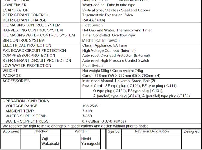
4 I. SPECIFICATIONS 1. SPECIFICATIONS [a] KMD-201AA (air-cooled) 1
![[b]](/docs-images/71/65813772/images/5-0.jpg)
5 [b] KMD-201AWA (water-cooled) 2
 Spray Tube Hot Gas Valve Condenser Thermistor Access Valve (Low Side) Expansion Valve")
6 II. GENERAL INFORMATION 1. CONSTRUCTION [a] KMD-201AA Water Supply Tube Spray Guide Drain Valve Water Supply Inlet Access Valve (High Side) Spray Tube Hot Gas Valve Condenser Thermistor Access Valve (Low Side) Expansion Valve Fan Motor Compressor Cube Guide Water Tank Pump Motor Float Switch Control Box Harvest Water Valve Fill Water Valve Control Switch Service Switch Fuse Holder (Fuse) Drier Bin Control Switch 3
![[b] KMD-201AWA Water Supply Tube Spray Guide Drain Valve Water Supply Inlet Access Valve (High Side) Spray Tube Hot Gas Valve Water Regulator Thermistor Access Valve (Low Side) Expansion](/docs-images/71/65813772/images/7-1.jpg "Valve Condenser Compressor Cube Guide Drier Water Tank Pump Motor Float Switch Control Box Harvest Water Valve Fill Water Valve Control Switch Service Switch Fuse Holder (Fuse) Bin Control")
7 [b] KMD-201AWA Water Supply Tube Spray Guide Drain Valve Water Supply Inlet Access Valve (High Side) Spray Tube Hot Gas Valve Water Regulator Thermistor Access Valve (Low Side) Expansion Valve Condenser Compressor Cube Guide Drier Water Tank Pump Motor Float Switch Control Box Harvest Water Valve Fill Water Valve Control Switch Service Switch Fuse Holder (Fuse) Bin Control Switch 4
8 2. SEQUENCE OF OPERATION The steps in the sequence are as outlined below. When power is supplied, a 5 second delay occurs at startup. Note that the order of the LEDs from the outer edge of the board is 5, 6, 8, 9, 4, 7. [a] ONE MINUTE FILL CYCLE LED 8 is on. HWV opens and the fill period begins. After 1 minute, the board checks for a closed LF/S. If LF/S is closed, the harvest cycle begins. If not, HWV will remain energized through additional 1 minute cycles until water enters the sump and LF/S closes. This serves as a low water safety to protect the water pump. [b] INITIAL HARVEST CYCLE LEDs 5, 6, and 8 are on. HWV remains open, Comp energizes, HGV opens, and harvest begins. As the evaporator warms, the thermistor located on the suction line checks for a 9 C temperature. When 9 C is reached, a 3.9 kω signal turns the harvest over to the adjustable harvest timer which is factory set for normal conditions. The timer has settings of 60, 90, 120, and 180 seconds (S1 dip switch 1 & 2). When the harvest timer completes its count down, the harvest cycle is complete and the freeze cycle starts. The minimum total time allowed by the board for a complete harvest cycle is 2 minutes. HWV is open during harvest for a maximum of 6 minutes or the length of harvest minus 0, 10, 30, or 50 seconds (adjustable by S1 dip switch 7 & 8), whichever is shorter. LED 8 goes off when HWV closes. PM energizes and runs for the last 0, 10, 30, or 50 seconds of harvest depending on S1 dip switch 7 & 8 setting. LED 7 comes on when PM energizes. At the end of harvest, the control board checks the position of LF/S and proceeds to the freeze cycle if it is closed or calls for a 1-minute fill if it is open. [c] FREEZE CYCLE LEDs 5 & 7 are on. Comp continues to run, PM and FMS energize, HGV closes and the freeze cycle starts. For the first 5 minutes after the thermistor temperature reaches 2 C, the control board will not accept a signal from LF/S and UF/S. This minimum freeze period acts as a short cycle protection. At the end of this period, LF/S and UF/S assumes control. As ice builds on the evaporator the water level in the sump lowers and LF/S opens, FWV opens (LED 9 is on when FWV is open). The refill will last until UF/S closes or for 60 seconds, whichever is shorter. After UF/S closes, FWV closes 3 seconds later. KMD-201 refills 1 time. After the refill, the freeze continues until LF/S opens again and terminates ice production. [d] DRAIN CYCLE LEDs 4, 5, 6, and 7 are on. Comp continues to run, HGV opens, FMS de-energizes. PM stops for 2 seconds, DV energizes, then restarts to take water from the sump and force it through DV and down the drain. When the drain timer stops counting, the drain is complete. The drain timer is 10 or 20 seconds (S1 dip switch 3 & 4). Drain cycle always occurs on the 2nd harvest after startup. Then, depending on the control board setting, drain cycle occurs every cycle, or every 2nd, 5th, or 10th cycles (S1 dip switch 5 & 6). 5
9 [e] NORMAL HARVEST CYCLE LEDs 5, 6, and 8 are on. Comp continues to run, HGV remains open and HWV opens. As the evaporator warms, the thermistor reaches 9ºC. The control board then receives the thermistor s 3.9kΩ signal and starts the harvest timer. HWV is open during harvest for a maximum of 6 minutes or the length harvest minus 0, 10, 30, or 50 seconds (adjustable by S1 dip switch 7 & 8), whichever is shorter. LED 8 goes off when HWV closes. PM energizes and runs for the last 0, 10, 30, or 50 seconds of harvest depending on S1 dip switch 7 & 8 setting. LED 7 comes on when PM energizes. At the end of harvest, the control board checks for the position of LF/S and proceeds to the freeze cycle if it is closed or calls for a 1-minute fill if it is open. The unit continues to cycle through [c], [d], and [e] sequence until the bin control is activated and shuts the unit down. When the bin control is activated, the POWER OK LED flashes. Note: To prevent incomplete batches of ice from foaming on the evaporator, the control board will only shut down the machine within the first 5 minutes of the freeze cycle after the thermistor temperature reaches 2 ºC. If ice pushes the bin control actuator in (open) after this minimum freeze period, the control board will allow the machine to complete the freeze cycle and the following harvest cycle before shutting down the machine. Legend: Comp compressor; DV drain valve; FMS self-contained fan motor; FWV fill water valve; HGV hot gas valve; HWV harvest water valve; LF/S lower float switch contacts; UF/S upper float switch contacts; PM pump motor 6


10 KMD-201AA, 201AWA Maximum harvest water valve time: 6 minutes (HWV time is 6 minutes of the length of harvest minus 0, 10, 30, or 50 sec. (S1 dip switch 7 & 8), whichever is shorter. PM energizes and runs for the last 0, 10, 30, or 50 sec. of harvest.) Maximum harvest time: 20 minutes 0, 0,30, or 50 sec H board will have 5 second delay HWV energized COMP energized HGV energized HWV continues FWV de-energized DV de-energized Legend: COMP - compressor DV drain valve FMS self-contained fan motor FWV fill water valve HGV hot gas valve HWV harvest water valve LF/S lower float switch contacts PM pump motor UF/S upper float switch contacts Minimum freeze time: 5 minutes Maximum freeze time: freeze time setting Lower float switch used to initiate water Tank refill (1 refill for KMD-201) Upper float switch used to terminate water tank refill (1 minute maximum fill time) COMP continues PM continues FWV energized/ de-energized for refill only FMS energized HGV de-energized 4. Drain Cycle Factory set for every 10 th cycle (S1 dip Switch 5 & 6) Pump motor stops for 2 sec. and then runs for 10/20 sec. (S1 dip switch 3 & 4) PM de-energizes 0/2 sec., energizes for 10/20 sec. COMP continues DV energized/ HGV energized FMS de-energized 7
11 3. CONTROL BOARD * A HOSHIZAKI exclusive solid-state control is employed in KMD-201AA and KMD-201AWA Crescent Cubers. * All models are pretested and factory-adjusted. 1. Fragile, handle very carefully. 2. A control board contains integrated circuits, which are susceptible to failure due to static discharge. It is especially important to touch the metal part of the unit when handling or replacing the board. 3. Do not touch the electronic devices on the board or the back of the board to prevent damage to the board. 4. Do not change wiring and connections. 5. Always replace the whole board assembly if it goes bad. 6. Do not short out power supply to test for voltage. 8
![[a] CONTROL BOARD LAYOUT #4 Harvest Water](/docs-images/71/65813772/images/12-0.jpg "Valve #5 Freeze Water Valve #1, 2, 3 Float")
12 [a] CONTROL BOARD LAYOUT #4 Harvest Water Valve #5 Freeze Water Valve #1, 2, 3 Float Switch 9
13 [b] FEATURES a) Maximum Water Supply Period - 6 minutes The harvest water valve will be open during harvest for 6 minutes or the length of harvest minus 0, 10, 30, or 50 seconds (adjustable by S dip switch 7 & 8), whichever is shorter. b) Harvest Backup Timer and Freeze Timer The harvest backup timer shuts down the icemaker if, for two cycles in a row, the harvest cycle takes more than 20 minutes to complete. The control board will signal this problem using 2 beeps every 3 seconds. The freeze timer shuts down the icemaker if, for two cycles in a row, the freeze cycle takes longer than the time specified to complete. The control board will signal this problem using 3 beeps every 3 seconds. The time is factory set using S1 dip switch 9 & 10. The alarm reset button on the control board must be pressed with power on to reset either of these safeties. c) High Temperature Safety The temperature of the suction line in the refrigeration circuit is limited by the high temperature safety. This protects the unit from excessively high temperatures. If the evaporator temperature rises above 53 C ± 4 C, the thermistor operates the safety. This shuts down the circuit and the icemaker automatically stops. The control board will signal this problem using 1 beep every 3 seconds. The alarm reset button on the control board must be pressed with power on to reset the safety. d) Low Water Safety The control board checks the position of the lower float switch at the end of the initial one minute water fill cycle and at the end of each harvest cycle. If the lower float switch is in the up position (electrical circuit closed), the control board changes to the next cycle. If the lower float switch is in the down position (electrical circuit open), the control board changes to additional one minute water fill cycles until water enters the sump and the float switch closes. When the float switch closes, the control board changes to the next cycle. The unit will not start without adequate water in the sump. This serves as a low water safety to protect the water pump. For water-cooled model, if the condenser water supply is shut off, the unit is protected by the high-pressure switch. e) High Voltage and Low Voltage Cut-outs The maximum and minimum allowable supply voltages of this icemaker are limited by the high voltage and low voltage cut-outs. If miswiring (especially on single 3 phase wire models) causes excessive voltage ( 294 Vac ± 5% or more) on the control board, the high voltage cut-out shuts down the circuit in 3 seconds and the icemaker automatically stops. The control board will signal this problem using 7 beeps every 3 seconds. The icemaker also automatically stops in cases of insufficient voltage (184Vac ± 5% or less). The control board will signal this problem using 6 beeps every 3 seconds. When the proper supply voltage is resumed, the icemaker automatically starts running again. 10

14 f) LED Lights and Audible Alarm Safeties The control board includes LED indicator lights, audible alarm safeties, and an output test feature. The "POWER OK" LED indicates control voltage and will remain on unless a control voltage problem occurs. The POWER OK LED flashes continuously when the bin is full and DV energizes for a maximum of 5 minutes to drain the water tank. At startup, a 5 second delay occurs to stabilize the circuit. LEDs 4 through 8 energize and sequence from initial startup as listed in the table below. Note that the order of the LEDs from the outer edge of the board is 5, 6, 8, 9, 4, 7. For more information, see "2. SEQUENCE OF OPERATION". HWV HWV, HGV, Comp 5, 7 (and 9 at refill) Comp, PM, FMS (FWV at refill) DV- drain valve; FMS-self-contained fan motor; WRV-water regulating valve; 11
![[c] CONTROLS AND ADJUSTMENTS a) Default Dip Switch Settings The dip switch is factory-adjusted to the following positions: KMD-201AA(50Hz)](/docs-images/71/65813772/images/15-2.jpg "KMD-201AA(60Hz) KMD-201AWA(50Hz) KMD-201AWA(60Hz) KMD-201AA(50Hz) KMD-201AA(60Hz) KMD-201AWA(50Hz) KMD-201AWA(60Hz) Do not adjust the S2 dip")
 Harvest Timer (S1 dip switch 1 & 2) Used for adjustment of the harvest timer.")
15 [c] CONTROLS AND ADJUSTMENTS a) Default Dip Switch Settings The dip switch is factory-adjusted to the following positions: KMD-201AA(50Hz) KMD-201AA(60Hz) KMD-201AWA(50Hz) KMD-201AWA(60Hz) KMD-201AA(50Hz) KMD-201AA(60Hz) KMD-201AWA(50Hz) KMD-201AWA(60Hz) Do not adjust the S2 dip switch. These must be left in the factory default position, or the unit will not operate properly. b) Harvest Timer (S1 dip switch 1 & 2) Used for adjustment of the harvest timer. The harvest timer starts counting when the thermistor reads a certain temperature at the evaporator outlet. 12

16 c) Drain Timer (S1 dip switch 3 & 4) Once every ten freeze cycles, the drain valve opens to drain the water tank for the time determined by the drain timer. These switches also determine the time to delay completion of a defrost cycle, i.e. the minimum defrost time. Do not change this setting, or the unit will not operate properly or produce high quality ice. T1: Time to drain the water tank T2: Harvest timer at drain Drain cycle always occurs on the 2nd harvest after startup. Then, depending on the drain frequency control setting (dip switch 5 & 6), drain cycle occurs every cycle, or every 2nd, 5th, or 10th cycle. d) Drain Frequency Control (S1 dip switch 5 & 6) The water tank drains at the frequency set by the drain frequency control. The drain frequency control is factory-adjusted to drain the water tank every 10 cycles, and no adjustment is required. However, where water quality is bad and the icemaker needs a drain more often, the drain frequency can be adjusted as shown in the table below. e) Water Saver Timer (S1 dip switch 7 & 8) The water saver timer allows the water valve to close and the pump motor to circulate water in the tank during the final part of harvest. The water valve is open during harvest for a maximum of 6 minutes or the length of harvest minus 0, 10, 30, or 50 seconds (determined by the water saver timer setting), whichever is shorter. When the water valve closes, the pump motor energizes and runs for the time determined by the water saver timer setting. The water saver timer is factory-adjusted, and no adjustment is required. 13

 (minutes) 60/60 60/50 100/70 120/100 g) Pump-Out Pump Motor Delay (S2 dip switch 1) The pump-out pump motor delay determines whether or not the pump motor de-energizes for 2 seconds")
17 f) Freeze Timer (S1 dip switch 9 & 10) The freeze timer setting determines the maximum allowed freeze time to prevent possible freeze-up issues. Upon termination of freeze timer, machine initiates the harvest cycle. After 2 consecutive timer terminations, machine will shut down, possibly indicating a problem. The freeze timer is factory adjusted, and no adjustment is required. Time(50/60Hz) (minutes) 60/60 60/50 100/70 120/100 g) Pump-Out Pump Motor Delay (S2 dip switch 1) The pump-out pump motor delay determines whether or not the pump motor de-energizes for 2 seconds before restarting at the beginning of a drain cycle. The pump-out pump motor delay is factory adjusted and no adjustment is required. h) Refill Counter (S2 dip switch 2, 3, & 4) Do not adjust. These must be left in the factory default position or the unit will not operate properly. The KMD-201AA and KMD-201AWA refill 1 time. i) Factory Use (S2 Dip Switch 5) Must remain off. j) Anti-Slush Control (S2 dip switch 6) The anti-slush control helps prevent slushing during the freeze cycle on small icemakers. It is deactivated on the KMD-201 series. When activated, the thermistor located on the suction line checks for a 34 ºF (1 ºC) temperature as the evaporator cools. When 34 ºF (1 ºC) is reached, a 5.9 kω signal causes the control board to de-energize the pump motor for 10 seconds. Do not adjust. This must be left in the factory default position or the unit will not operate properly. 14
![[d] CONTROL BOARD CHECK PROCEDURE Before replacing a control board that does not show a visible defect and that you suspect is bad, always conduct the following check procedure.](/docs-images/71/65813772/images/18-1.jpg "This procedure will help you verify your diagnosis. 1) Check the dip switch settings to assure that S1 dip switch 3, 4, 7, 8, 9, & 10 and S2 dip switch 1 through 6 are in the factory default position.")
18 [d] CONTROL BOARD CHECK PROCEDURE Before replacing a control board that does not show a visible defect and that you suspect is bad, always conduct the following check procedure. This procedure will help you verify your diagnosis. 1) Check the dip switch settings to assure that S1 dip switch 3, 4, 7, 8, 9, & 10 and S2 dip switch 1 through 6 are in the factory default position. S1 dip switch 1, 2, 5, & 6 are cleaning adjustments and the settings are flexible. 2) Move the control switch to the "ICE" position and check for proper control voltage. If the "POWER OK" LED is on, the control voltage is good. If the "POWER OK" LED is off, check the control transformer circuit. If no voltage is present, check the power supply circuit. 3) The output test button provides a relay sequence test. Make sure the control switch is in the "ICE" position, then press the "OUTPUT TEST" button. The correct lighting sequence should be 5, 6, 7, 8, 9, 4. Some components (e.g., the compressor) will cycle during the test. Each LED flashes three times in 5 seconds. LED 5 continues to flash while LED 6 flashes. Following the output test sequence, the icemaker will resume normal operation beginning with the 1 minute fill cycle. [e] CONTROL BOARD REPLACEMENT The dip switches should be adjusted to the factory default settings as outlined in this manual. S2 dip switch 5 must remain off. 4. HARVEST CONTROL THERMISTOR A thermistor (semiconductor) is used as a harvest control sensor and anti-slush sensor. The resistance varies depending on the suction line temperatures. The thermistor detects the temperature of the evaporator outlet to start the harvest timer or momentarily stop the pump motor during the freeze cycle. No adjustment is required. If necessary, check for resistance between thermistor leads, and visually check the thermistor mounting, located on the suction line next to the evaporator outlet. Check a thermistor for resistance by using the following procedure: 1) Disconnect the thermistor (orange wires) at the 2-pin connector on the control box. See Fig. 1. 2) Remove the thermistor. See "V. 17. THERMISTOR." 3) Immerse the thermistor sensor portion in a glass containing ice and water for 2 or 3 minutes. 4) Check for a resistance between thermistor leads. Normal reading is within 3.5 to 7 kω. Replace the thermistor if it exceeds the normal reading. Thermistor Connector (orange wires) Bin Control Wires (black) Float Switch Connector (red wires) 15
19 5. FLOAT SWITCH [a] EXPLANATION OF OPERATION The float operates 2 switches within the float switch. The lower switch (black and blue wires) is used for low water safety protection, initiating the freeze cycle refill and terminating the freeze cycle. The upper switch (black and red wires) is used to terminate the freeze cycle refill only. Refill will last until the upper float switch closes or the 1 minute countdown timer ends, whichever comes first. [b] CLEANING Depending on local water conditions, scale may build up on the float, float switch shaft and inside the housing. Scale on the float or shaft can cause the float to stick causing erratic operation. The float switch should be cleaned and checked before replacing. First, disconnect the float switch connector from the control box and remove the water tank and pump motor bracket together from the icemaker. Twist the mechanical lock inside of the pump motor bracket and remove the float switch. See "V. 15. FLOAT SWITCH." Remove the retainer clip from the shaft and slide the float off the shaft. Soak the switch assembly in ice machine cleaner. Wipe down the shaft, float, housing with cleaning solution. See "VI. CLEANING AND MAINTENANCE INSTRUCTIONS." [c] FLOAT SWITCH CHECK PROCEDURE Before replacing a float switch that you suspect is bad, make sure the float switch has been cleaned. This procedure will help you verify your diagnosis. The float switch has three wires. The black wire is common. The blue wire is for the lower float switch contact and the red wire is for the upper float switch contact. 1) Disconnect the black float switch connector from the control box. 2) Drain the reservoir water. 3) Turn the control switch to "ICE". 4) As water fills the reservoir, the float switch contacts should close. Check continuity of the lower float switch contacts using the black and blue wires and the upper float switch contacts using the black and red wires. With the float positioned all the way up, both float switch contacts should be closed. If either float switch contact fails, the assembly should be replaced. 5) Turn the control switch to "OFF". 6) Drain the reservoir water. 7) As water drains, the float switch contacts should open. Check continuity of the upper float switch contacts using the black and red wires and the lower float switch contacts using the black and blue wires. With the float positioned all the way down, both float switch contacts should be open. If either float switch contact fails, the assembly should be replaced. 8) Reconnect the black connector to the control box when finished. 16
20 6. BIN CONTROL This machine uses a lever-actuated proximity switch (mechanical bin control) to control the ice level in the storage bin. No adjustment is required. [a] EXPLANATION OF OPERATION The bin control is connected to the K1 connector (pins 4 & 5) on the control board. When the bin control is calling for ice (proximity switch closed; "POWER OK" LED on), the control board continues icemaking operations. When the bin control is activated in the bin full position (proximity switch open; "POWER OK" LED flashing), the control board drains and shuts down the unit. However, to prevent incomplete batches of ice from forming on the evaporator, the control board will only shut down the machine during the freeze cycle before the five minute timer expires. The five minute timer starts counting down when the thermistor temperature reaches 2 C. If, during the freeze cycle, ice pushes in the lever after the five minute timer expires, the control board will allow the machine to complete the freeze cycle and the following harvest cycle before shutting down the machine. [b] BIN CONTROL CHECK PROCEDURE 1) Clear any ice away from the bin control. 2) Make sure the control switch is in the "ICE" position. 3) Check that the "POWER OK" LED on the control board is on. 4) Activate the bin control actuator (press the actuator in). Check that the "POWER OK" LED flashes. 5) Disconnect the bin control at the 2-pin connector attached to the black wires coming from the K1 connector (pins 4 & 5) on the control board. 6) Check for continuity across the bin control leads. When calling for ice, the bin control proximity switch should be closed. If open, replace the bin control. Activate the bin control actuator (press the actuator in), check for continuity across the bin control leads. The bin control proximity switch should be open. If closed, replace the bin control. 7) Reconnect the 2-pin connector. Allow the machine to cycle into the freeze cycle. In the first 5 minutes of the freeze cycle, activate the bin control actuator (press the actuator in). The "POWER OK" LED should flash and the machine should turn off. If not, replace the control board. 17
21 7. SWITCHES Two different control switches are used for operation of KMD-201AA and KMD-201AWA. These switches are referred to as the "control switch" and the "service switch" and are located on the control box. [a] CONTROL SWITCH This switch is used to place the machine into one of three modes: OFF (center position), ICE (upper position), and SERVICE (lower position). [b] SERVICE SWITCH When the control switch is placed in the SERVICE position, power is supplied to the service switch. The service switch can be used to perform two functions: draining the tank ( DRAIN = lower position) and washing the icemaking compartment ( WASH or CIRCULATE = upper or center position). Both the WASH and CIRCULATE positions activate the same function of washing the icemaking compartment. The service switch is activated in any of the three positions when the power is supplied to the pump motor. 1) DRAIN KMD-201AA and KMD-201AWA employ the pump-out drain system. When the service switch is active and placed in the lower position, power is supplied to the pump motor and drain valve. 2) WASH or CIRCULATE When the service switch is active and placed in the upper or center position, power is supplied to the pump motor. This function is to clean the evaporator plate. 18
22 III. TECHNICAL INFORMATION 1. WATER CIRCUIT AND REFRIGERANT CIRCUIT 19
23 2. WIRING DIAGRAM 20

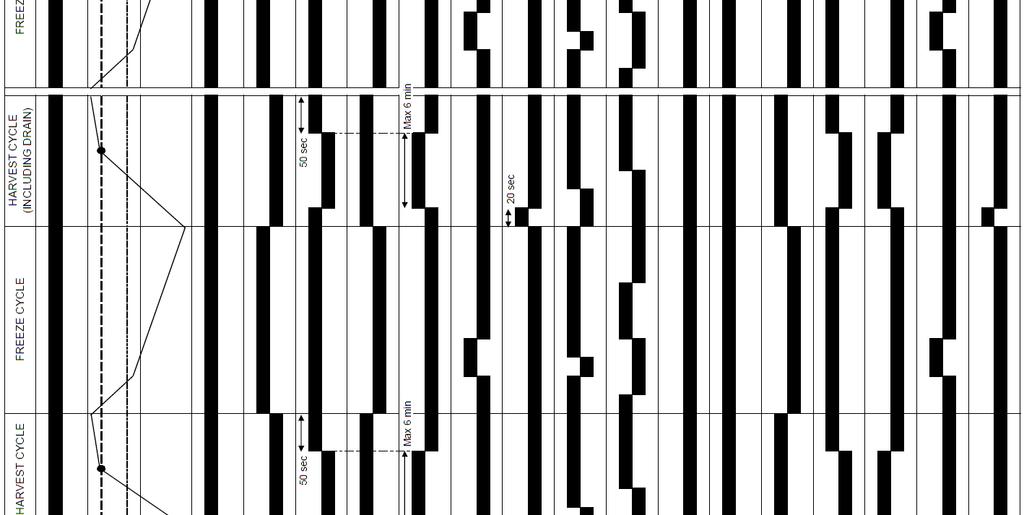
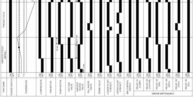
24 3. TIMING CHART 21
25 IV. SERVICE DIAGNOSIS MINUTE DIAGNOSTIC PROCEDURE The 10 minute check out procedure is basically a sequence check which can be used at unit start-up or for system diagnosis. Using this check out procedure will allow you to diagnose electrical system and component failures in approximately 10 minutes under normal operating conditions of 21 C or warmer air and 10 C or warmer water temperatures. Before conducting a 10 minute checkout, check for correct installation, proper voltage per unit nameplate and adequate water supply. As you go through the procedure, check to assure the components energize and de-energize correctly. If not, those components and controls are suspect. 1) Turn power off and access the control box. Clear any ice from the bin control actuator located in the bin. 2) Turn power on and place the control switch in the "ICE" position. A 5 second delay occurs. The "POWER OK" LED on the control board comes on. If the "POWER OK" LED is flashing (indicating a full bin), check the bin control. See "II. 6. [b] BIN CONTROL CHECK PROCEDURE." 3) One Minute Fill Cycle The harvest water valve is energized. After 1 minute, the control board checks the float switch. If the lower float switch is closed, the unit cycles to harvest. If closed, continue to step 4. If the lower float switch is open, the unit repeats the 1 minute fill cycle until water enters and the lower float switch closes (low water safety protection during initial start up and at the end of each harvest). Diagnosis: If the water valve does not open, check for no supply voltage at water valve terminals, bad coil, or plugged screen or external filter (no water flow). If unit fails to start harvest, check for open float switch or bad 1 minute timer in board. 4) Initial Harvest Cycle The harvest water valve remains energized, contactor coil energizes to start the compressor (and fan motor on a remote condenser unit), and the hot gas valve energizes. The evaporator warms and the thermistor senses 48 F (9 C). The control board then receives the thermistor's 3.9 kω signal and turns operation of harvest over to the harvest timer. The timer completes counting (1 to 3 minutes). The unit then cycles to freeze. Diagnosis: Check if compressor is running, hot gas valve is open, harvest water valve still open. Average harvest cycle at factory setting is 2 to 4 minutes. How long does initial harvest last? 1.5 minutes after initial harvest begins, touch the compressor discharge line. Is it hot? If not, check refrigerant pressures and compressor operation. If it is hot, touch the inlet line to the evaporator. Is it hot? If it is hot and the freeze cycle is not starting, check the harvest timer adjustment, the thermistor for open circuit, the discharge line temperature, compressor efficiency, and if the hot gas valve is fully open. 5) Freeze Cycle The compressor remains energized, pump motor, (line valve if applicable), and fan motor energize. The harvest water valve and hot gas valve de-energize. The unit is held in freeze by a 5 minute short cycle protection timer which starts after the thermistor temperature reaches 2 C. After this period, the freeze cycle operation is transferred to the float switch for freeze termination. The lower float switch activates (open) 2 times during the course of a freeze cycle; the first is for refill, the second is for freeze termination. After the second lower float switch activation, the control board terminates freeze and initiates harvest. 22
26 a. Lower Float Switch 1st Activation: Refill The refill can occur at any time during the freeze cycle (1 refill per cycle). As ice builds the water level drops in the reservoir and the lower float switch activates (opens). LED 5 comes on and the control board energizes the fill water valve. The fill water valve remains energized until the upper float switch closes or the 1 minute fill timer terminates, whichever comes first. b. Lower Float Switch 2nd Activation: The unit is held in freeze by a 5 minute short cycle protection timer which starts after the thermistor temperature reaches 2 C. After the 1st lower float switch activation and refill, ice continues to form and the water level drops in the reservoir. When the lower float switch activates (opens) a second time, the freeze cycle terminates (freeze can only be terminated on the second activation of the lower float switch and after the minimum freeze period). Diagnosis: During the minimum freeze period, confirm that the evaporator temperature drops, compressor, fan motors and pump motor are energized and that the hot gas valves, harvest water valve and fill water valve (except during refill) are de-energized and not bypassing. Make sure the expansion valves are operating properly and, in cold conditions. Make sure that the drain water valve is not leaking by (water flowing down the potable drain). Check for proper unit pressures, or an inoperative compressor. Disconnect the 3-pin float switch connector from the control box. 15 seconds after disconnecting the 3-pin float switch connector, LED 5 comes on and refill begins. Connect the 3-pin float switch connector back on the control box. When the refill is finished (LED 5 goes off), disconnect the 3-pin float switch connector again. If 5 or more minutes have elapsed in the freeze cycle, the unit should switch out of the freeze cycle. After the unit switches out of freeze, reconnect the 3-pin float switch connector to the control box. If the unit remains in freeze with the float switch disconnected, replace the board. To check the float switch, see "II. 5. [c] FLOAT SWITCH CHECK PROCEDURE." Note: Normal freeze cycle will last 20 to 40 minutes depending on model and conditions. Cycle times and pressures should follow performance data provided in this manual. 6) Drain Cycle The compressor remains energized, the hot gas valve energizes, the fan motor de-energizes. The drain valve and pump motor energize, allowing water to drain from the tank for 20 seconds. This removes contaminants from the water tank. Diagnosis: If the drain valve does not open, check the circuit. Check for proper voltage. If water does not drain out, check and clean the tubing at the drain valve and then check and clean the valve assembly. 7) Normal Harvest Cycle same as the initial harvest cycle Return to step 4. Note: Unit continues to cycle until bin control is satisfied or power is turned off. (The drain cycle can be adjusted to occur every cycle, or every 2, 5, or 10 cycles. The factory default is every 10 cycles.) The unit always restarts at the 1 minute fill cycle. 23
27 2. DIAGNOSTIC CHARTS [a] NO ICE PRODUCTION 2. See "II. 6. [b] Bin Control Check Procedure." 5. See chart [a] [7]. 24
28 1. See "II. 4. Harvest Control - Thermistor." 1. See "II. 3. [d] Control Board Check Procedure." 1. See "II. 3. [d] Control Board Check Procedure." 25
29 1. See "II. 3. [d] Control Board Check Procedure." 1. See "II. 3. [d] Control Board Check Procedure." 1. See "II. 3. [d] Control Board Check Procedure." 1. See "II. 3. [d] Control Board Check Procedure." 1. See "II. 3. [d] Control Board Check Procedure." 26
![1. Adjust or replace. See "V. 9. Adjustment of Water Regulating Valve." [b] EVAPORATOR IS FROZEN UP 1. See "II. 3.](/docs-images/71/65813772/images/30-1.jpg "[d] Control Board Check Procedure.\" 1. See \"V. 17. Thermistor.\" 1. See \"II. 3.")
30 1. Adjust or replace. See "V. 9. Adjustment of Water Regulating Valve." [b] EVAPORATOR IS FROZEN UP 1. See "II. 3. [d] Control Board Check Procedure." 1. See "V. 17. Thermistor." 1. See "II. 3. [c] Controls and Adjustments, b) Harvest Timer." 27
![1. See "II. 3. [d] Control Board Check Procedure.](/docs-images/71/65813772/images/31-1.jpg "\" [c] LOW ICE PRODUCTION a) See chart [b] [1] and check float switch, fill and harvest water valves, control board, water pump, spray tubes, evaporator, and expansion valve.")
31 1. See "II. 3. [d] Control Board Check Procedure." [c] LOW ICE PRODUCTION a) See chart [b] [1] and check float switch, fill and harvest water valves, control board, water pump, spray tubes, evaporator, and expansion valve. b) See chart [a] [1] and check dirty air filter or condenser, ambient or water temperature, refrigerant charge, water pressure, and condenser water regulating valve (water-cooled model only). a) See chart [b] [2] and check evaporator, water supply line, harvest water valve, ambient and/or water temperature, line valve (if applicable), thermistor, control board, and hot gas valve. [d] ABNORMAL ICE a) Ice Cube Guide, Water Tank, Deflector 28
![a) See chart [b] [1] & [3] and check float switch, fill and harvest water valves, control board, spray tubes, water system,](/docs-images/71/65813772/images/32-0.jpg "refrigerant charge, and expansion valve. [e] OTHER 1. See \"II. 6. [b] Bin Control Check Procedure.")
32 a) See chart [b] [1] & [3] and check float switch, fill and harvest water valves, control board, spray tubes, water system, refrigerant charge, and expansion valve. [e] OTHER 1. See "II. 6. [b] Bin Control Check Procedure." c) Ice Cube Guide, Water Tank, Deflector 29
33 V. REMOVAL AND REPLACEMENT 1. SERVICE FOR REFRIGERANT LINES [a] SERVICE INFORMATION 1) Allowable Compressor Opening Time and Prevention of Lubricant Mixture [R404A] The compressor must not be opened more than 15 minutes in replacement or service. Do not mix lubricants of different compressors even if both are charged with the same refrigerant, except when they use the same lubricant. 2) Treatment for Refrigerant Leak [R404A] If a refrigerant leak occurs in the low side of an ice maker, air may be drawn in. Even if the low side pressure is higher than the atmospheric pressure in normal operation, a continuous refrigerant leak will eventually lower the low side pressure below the atmospheric pressure and will cause air suction. Air contains a large amount of moisture, and ester oil easily absorbs a lot of moisture. If an ice maker charged with R404A has possibly drawn in air, the drier must be replaced. Be sure to use a drier designed for R404A. 3) Handling of Handy Flux [R404A] Repair of the refrigerant circuit requires brazing. It is no problem to use the same handy flux that has been used for the current refrigerants. However, its entrance into the refrigerant circuit should be avoided as much as possible. 4) Oil for Processing of Copper Tubing [R404A] When processing the copper tubing for service, wipe off oil, if any used, by using alcohol or the like. Do not use too much oil or let it into the tubing, as wax contained in the oil will clog the capillary tubing. 5) Service Parts for R404A Some parts used for refrigerants other than R404A are similar to those for R404A. But never use any parts unless they are specified for R404A because their endurance against the refrigerant have not been evaluated. Also, for R404A, do not use any parts that have been used for other refrigerants. Otherwise, wax and chlorine remaining on the parts may adversely affect R404A. 6) Replacement Copper Tubing [R404A] The copper tubes currently in use are suitable for R404A. But do not use them if oily inside. The residual oil in copper tubes should be as little as possible. (Low residual oil type copper tubes are used in the shipped units.) 30
34 7) Evacuation, Vacuum Pump and Refrigerant Charge [R404A] Never allow the oil in the vacuum pump to flow backward. The vacuum level and vacuum pump may be the same as those for the current refrigerants. However, the rubber hose and gauge manifold to be used for evacuation and refrigerant charge should be exclusively for R404A. 8) Refrigerant Leak Check Refrigerant leaks can be detected by charging the unit with a little refrigerant, raising the pressure with nitrogen and using an electronic detector. Do not use air or oxygen instead of nitrogen for this purpose, or rise in pressure as well as in temperature may cause R404A to suddenly react with oxygen and explode. Be sure to use nitrogen to prevent explosion. [b] REFRIGERANT RECOVERY The icemaker unit is provided with refrigerant access valves. Using proper refrigerant practices, recover the refrigerant from the access valves and store it in an approved container. Do not discharge the refrigerant into the atmosphere. [c] EVACUATION AND RECHARGE 1) Attach a vacuum pump to the system. Be sure to connect charging hoses to both high and low-side access valves. 2) Turn on the vacuum pump. Open the service manifold valves. Never allow the oil in the vacuum pump to flow backwards. 3) Allow the vacuum pump to pull down to a 760 mmhg vacuum. Evacuating period depends on pump capacity. 4) Close the low-side valve and high-side valve on the service manifold. 5) Disconnect the vacuum pump and attach a refrigerant service cylinder to the high-side line. Remember to loosen the connection and purge the air from the hose. For air-cooled and water-cooled models, see the nameplate for the required refrigerant charge. 6) A liquid charge is recommended for charging an R-404A system. Invert the service cylinder and place it on scales. Open the high-side valve on the service manifold. 7) Allow the system to charge with liquid until the proper charge weight is met. 8) If necessary, add any remaining charge to the system through the low-side. Use a throttling valve or liquid dispensing device to add the remaining liquid charge through the low-side access port with the unit running. 9) Close the service manifold valves and disconnect the service manifold hoses. 10) Cap the access valves to prevent a possible leak. 31

 Turn off the power supply.")
35 2. BRAZING Note: All brazing connections inside the bin are clear coated. Sandpaper the brazing connections before unbrazing the components. Use a good abrasive cloth to remove the coating. 3. COMPRESSOR 1) Turn off the power supply. 2) Remove the panels and water tank. See "V. 14. WATER TANK." 32
36 3) Recover the refrigerant and store it in an approved container. 4) Remove the terminal cover on the compressor and disconnect the compressor wiring. 5) Remove the hold-down bolts, washers, and rubber grommets. 6) Remove the discharge and suction pipes. 7) Remove the compressor. Unpack the new compressor package. 8) Attach the rubber grommets of the prior compressor. 9) Place the compressor in position and secure it using the bolts and washers. 10) Remove the drier, then place the new drier in position. 11) Remove plugs from the suction, discharge, and process pipes. 12) Braze all fittings while purging with nitrogen gas flowing at a pressure of 20 to 30 kpa. 13) Use an electronic leak detector or soap bubbles to check for leaks. Add a trace of refrigerant to the system (if using an electronic leak detector), and then raise the pressure using nitrogen gas (970 kpa). DO NOT use R-404A as a mixture with pressurized air for leak testing. 14) Evacuate the system, and charge it with refrigerant. For air-cooled and water-cooled models, see the nameplate for the required refrigerant charge. 15) Connect the terminals and replace the terminal cover in its correct position. 16) Replace the panels and water tank in their correct positions. 17) Turn on the power supply. Note: Hoshizaki recommends that Compressor starting electrics are always replaced at the same time as the Compressor. 4. DRIER 1) Turn off the power supply. 2) Remove the panels. 3) Recover the refrigerant and store it in an approved container. 4) Remove the Drier Holder, if any, and pull the Drier toward you for easy service. 33
 Check for leaks using nitrogen gas (970 kpa) and soap bubbles.")
![8) Evacuate the system and charge it with refrigerant (see "V. 1. [c] EVACUATION AND RECHARGE"). 9) Refit the panels in their correct positions. 10) Turn on the power supply.](/docs-images/71/65813772/images/37-1.jpg "Note: Always use a Drier of the correct capacity and refrigerant type. 5. HOT GAS VALVE 1) Turn off the power supply. 2) Remove the panels.")
37 5) Remove the Drier using brazing equipment. 6) Braze the new Drier, with the arrow on the Drier in the direction of the refrigerant flow. Use nitrogen gas at a pressure of 20 to 30 kpa when brazing tubings. Braze in an Access Valve using a tee if necessary. 7) Check for leaks using nitrogen gas (970 kpa) and soap bubbles. 8) Evacuate the system and charge it with refrigerant (see "V. 1. [c] EVACUATION AND RECHARGE"). 9) Refit the panels in their correct positions. 10) Turn on the power supply. Note: Always use a Drier of the correct capacity and refrigerant type. 5. HOT GAS VALVE 1) Turn off the power supply. 2) Remove the panels. 3) Recover the refrigerant and store it in an approved container. 4) Disconnect the Hot Gas Valve leads. 5) Remove the screw and the Solenoid Coil. 6) Remove the valve and Drier using brazing equipment. 7) Braze the new Hot Gas Valve with nitrogen gas flowing at a pressure of 20 to 30 kpa. 34
![8) Install the new Drier (see "V. 4. DRIER"). 9) Check for leaks using nitrogen gas (970 kpa) and soap bubbles. 10) Evacuate the system and charge it with refrigerant (see "V. 1. [c] EVACUATION AND RECHARGE").](/docs-images/71/65813772/images/38-0.jpg "11) Attach the Solenoid Coil to the valve body, and secure it with the screw. 12) Connect the lead wires. 13) Refit the panels in their correct positions. 14) Turn on the power supply. 6.")
 Remove the insulation and the expansion valve bulb on the suction line. 5) Remove the expansion valve cover and disconnect the expansion valve. Place the new expansion valve in position.")
38 8) Install the new Drier (see "V. 4. DRIER"). 9) Check for leaks using nitrogen gas (970 kpa) and soap bubbles. 10) Evacuate the system and charge it with refrigerant (see "V. 1. [c] EVACUATION AND RECHARGE"). 11) Attach the Solenoid Coil to the valve body, and secure it with the screw. 12) Connect the lead wires. 13) Refit the panels in their correct positions. 14) Turn on the power supply. 6. EXPANSION VALVE 1) Turn off the power supply. 2) Remove the panels. 3) Recover the refrigerant and store it in an approved container. 4) Remove the insulation and the expansion valve bulb on the suction line. 5) Remove the expansion valve cover and disconnect the expansion valve. Place the new expansion valve in position. 6) Remove the drier, then place the new drier in position. 7) Braze all fittings while purging with nitrogen gas flowing at a pressure of 20 to 30 kpa. 8) Use an electronic leak detector or soap bubbles to check for leaks. Add a trace of refrigerant to the system (if using an electronic leak detector), and then raise the pressure using nitrogen gas (970 kpa). DO NOT use R-404A as a mixture with pressurized air for leak testing. 35
39 9) Evacuate the system, and charge it with refrigerant. For air-cooled and water-cooled models, see the nameplate for the required refrigerant charge. 10) Attach the expansion valve bulb to the suction line in the same location as the previous bulb. The bulb should be at the 12 o'clock position on the tube. Be sure to secure the bulb with the clamp and holder and to insulate it. 11) Place the expansion valve cover in position. 12) Replace the panels in their correct positions. 13) Turn on the power supply. 7. EVAPORATOR 1) Turn off the power supply. 2) Remove the panels and the front and top insulation. 3) Recover the refrigerant and store it in an approved container. 4) Remove the spray tubes. Remove the insulation at the "U" shaped notch where the refrigeration tubing passes through the molded chassis. 5) Disconnect the evaporator tubing. 6) Remove the pop rivets securing the evaporator, then lift out the evaporator. 7) Install the new evaporator. 8) Remove the drier, then place the new drier in position. 9) Braze all fittings while purging with nitrogen gas flowing at a pressure of 20 to 30 kpa. 10) Use an electronic leak detector or soap bubbles to check for leaks. Add a trace of refrigerant to the system (if using an electronic leak detector), and then raise the pressure using nitrogen gas (970 kpa). DO NOT use R-404A as a mixture with pressurized air for leak testing. 11) Evacuate the system, and charge it with refrigerant. For air-cooled and water-cooled models, see the nameplate for the required refrigerant charge. 12) Replace the removed parts in the reverse order of which they were removed. 13) Replace the insulation and the panels in their correct positions. 14) Turn on the power supply. 36
40 8. WATER REGULATING VALVE WATER-COOLED MODEL ONLY 1) Turn off the power supply. 2) Remove the panels. 3) Close the condenser water supply line shut-off valve, then open the condenser water supply line drain valve. 4) Attach a compressed air or carbon dioxide supply to the condenser water supply line drain valve. 5) Open the water regulating valve by using a screwdriver to pry up on the spring retainer underneath the spring. While holding the valve open, blow out the condenser using the compressed air or carbon dioxide supply until water stops coming out. 6) Recover the refrigerant and store it in an approved container. 7) Disconnect the capillary tube at the condenser outlet. 8) Disconnect the flare-connections of the valve. 9) Remove the screws and the valve from the bracket. 10) Install the new valve. 11) Remove the drier, then place the new drier in position. 12) Braze all fittings while purging with nitrogen gas flowing at a pressure of 20 to 30 kpa.. 13) Use an electronic leak detector or soap bubbles to check for leaks. Add a trace of refrigerant to the system (if using an electronic leak detector), and then raise the pressure using nitrogen gas (970 kpa). DO NOT use R-404A as a mixture with pressurized air for leak testing. 14) Evacuate the system, and charge it with refrigerant. See the nameplate for the required refrigerant charge. 15) Connect the flare-connections. 16) Close the condenser water supply line drain valve, then open the condenser water supply line shut-off valve. 17) Check for water leaks. 18) Replace the panels in their correct positions. 37
41 19) Turn on the power supply. 9. ADJUSTMENT OF WATER REGULATING VALVE WATER-COOLED MODEL ONLY The water regulating valve (also called "water regulator") is factory-adjusted. No adjustment is required under normal use. Adjust the water regulator, if necessary, using the following procedures. 1) Prepare a thermometer to check the condenser drain temperature. Attach a pressure gauge to the high-side line of the system. 2) Five minutes after a freeze cycle starts, confirm that the thermometer reads 40 ºC to 46 ºC. If it does not, rotate the adjustment screw by using a flat blade screwdriver until the temperature is in the proper range. See Fig. below. Next, check that the reference pressure is in the range indicated in the Head Pressure table in the Performance Data section. If it is not in the proper range, verify the refrigerant charge. 3) Check that the condenser drain temperature is stable. 10. FAN MOTOR 1) Turn off the power supply. 2) Remove the panels. 3) Loosen the two screws securing the Fan Blade Cover, then remove it. 4) Disconnect the Connector of the Fan Motor lead. 5) Loosen the far side of the two screws and remove the near side of the two screws securing the Fan Motor Bracket and slide out towards you. To prevent deformation, do not hit the Fan on the Condenser or other parts. 6) Install the new Fan Motor in the reverse order of the removal procedure. 7) Replace the panels in their correct positions. 8) Turn on the power supply. 38
 Turn off the power supply. 2) Remove the panels and front insulation.")
 Remove the Hose Band connecting the Discharge Hose.")
42 Screw (Loosen) Screw (Remove) Screw Fan Motor Fan Blade Cover Fan Motor Bracket 11. PUMP MOTOR 1) Turn off the power supply. 2) Remove the panels and front insulation. 3) Disconnect the Connector of the Pump Motor lead. 4) Remove the thumbscrew securing the Pump Motor. 5) Remove the Hose Band connecting the Discharge Hose. 6) Slide the Pump Motor at right slightly and lift it up towards you. Hose Band Thumbscrew Discharge Hose Pump Motor 39
43 7) Remove the Hose Band connecting the discharge outlet and pull off the Rubber Hose. 8) Install the new motor in the reverse order of the removal procedure. 9) Replace the panels and front insulation in their correct positions. 10) Turn on the power supply. 12. WATER VALVE 1) Turn off the power supply. 2) If replacing the harvest and/or fill water valve, close the icemaker water supply line shut-off valve. Open the icemaker water supply line drain valve. 3) Remove the panels. 4) Disconnect the tubing attached to the valve. If replacing the harvest and/or fill water valve, loosen the fitting nut. Be careful not to lose the washer. 5) Disconnect the terminals from the valve. 6) Remove the bracket and valve from the unit. 7) Install the new valve. Replace the removed parts in the reverse order of which they were removed. If replacing the harvest and/or fill water valve, make sure the washer is in place in the fitting nut. 8) If replacing the harvest and/or fill water valve, close the icemaker water supply line drain valve. Open the icemaker water supply line shut-off valve. 9) Turn on the power supply. 10) Check for leaks. 11) Replace the panels in their correct positions. 13. DRAIN VALVE 1) Turn off the power supply. 2) Close the water supply tap. 3) Remove the panels. 4) Disconnect the Connector of the Drain Valve lead. 5) Remove the Hose Clamps at the inlet and outlet sides. 6) Remove the Rubber Hoses at the inlet and outlet sides. 40
 Check for leaks. 12) Refit the panels in their correct positions. 14.")
44 7) Remove the two mounting screws. 8) Install the new valve in the reverse order of the removal procedure. 9) Open the water supply tap. 10) Plug in the icemaker or connect the power source. 11) Check for leaks. 12) Refit the panels in their correct positions. 14. WATER TANK 1) Remove the front panel, then remove the front insulation 2) Loosen the two thumbscrews securing the Pump Motor Bracket 3) Move the control switch to the "SERVICE" position. Move the service switch to the "DRAIN" position. 4) Let the icemaker run for 2 minutes. 5) Move the control switch to the "OFF" position. 6) Turn off the power supply. 7) Disconnect the Pump Motor and Float Switch connector from the side of the control box. 8) Keep pushing up the snapping tab at the right side of the Pump Motor Bracket. 9) Pull out the Water Tank, Cube Guide, Pump Motor Bracket, Pump Motor and Float Switch together. 41
 Refit the panels in their correct positions. 12) Turn on the power supply. 15.")
 Pull up the Pump Motor Bracket from the Water Tank.")
45 10) Install the new water tank in the reverse order of the removal procedure. 11) Refit the panels in their correct positions. 12) Turn on the power supply. 15. FLOAT SWITCH 1) Remove the Pump Motor Bracket. See "V. 14. WATER TANK." 2) Pull up the Pump Motor Bracket from the Water Tank. 3) Flip over the Pump Motor Bracket assembly, then twist off the Float Switch and pull out towards you. 42
 Remove the Water Tank. See \"V. 14. WATER TANK.\" 2) Disconnect the Connector of the Bin Control Switch lead (black).")
46 4) Install the new float switch in the reverse order of the removal procedure. 5) Refit the panels in their correct positions. 6) Turn on the power supply. 16. BIN CONTROL SWITCH 1) Remove the Water Tank. See "V. 14. WATER TANK." 2) Disconnect the Connector of the Bin Control Switch lead (black). 3) Pull out the Bin Control Switch Tab outside and slide the Bin Control Switch towards you. Bin Control Switch Tab 4) Take out the Bin Control. 5) Install the new bin control switch. 6) Pass the bin control connector through the hole from the bottom to the top of the unit. 7) While pulling up the bin control lead, hook the bin control on the right side interior wall. Then push the bin control up against the bottom of the unit, and slide to the back until it snaps in place. Make sure the slotted holes at the right side of the bin control are securely placed on the collars at the bottom of the unit. 43
47 8) Connect the bin control connector to the side of the control box. 9) Replace the water tank, cube guide, pump motor bracket, pump motor and float switch in their correct positions until they snap in place. 10) Secure the pump motor bracket with the two thumbscrews. 11) Reconnect the pump motor connector and float switch connector. 12) Replace the front insulation and front panel in their correct positions. 13) Turn on the power supply. 17. THERMISTOR 1) Turn off the power supply. 2) Remove the panels. 3) Disconnect the Connector of the Thermistor lead (orange). 4) Remove the Ties, Insulation, Thermistor Holder, and Thermistor in this order. 5) Remove the old sealant from the Thermistor Holder and Suction Pipe. 6) Wipe off any moisture or condensation from the Suction Pipe surfaces. 7) Press a tube of the sealant KE 60RTV, manufactured by Shin-Etsu Silicones, to the recess of the Thermistor Holder. Slowly squeeze the sealant out of the tube and spread it smoothly in the recess. Do not use any sealant other than the above. 8) Attach the new Thermistor in position on the Suction Pipe and press down the Thermistor Holder over the Thermistor. Be careful not to damage the Thermistor lead. Cover the parts with the Insulation and secure them with the Ties. Keep the Thermistor inside the Thermistor Holder. After the Thermistor Holder is fitted, do not pull the Thermistor lead to move the Thermistor. 44
 Remove the one mounting screw, and pull the Control Box Cover. 4) Remove the two mounting screws, and pivot the Control Box to the left side slightly and pull the Control Box towards you if needed.")
48 9) Refit the removed parts in the reverse order of the removal procedure. 10) Turn on the power supply. 18. CONTROL BOX 1) Turn off the power supply. 2) Remove the front panel. 3) Remove the one mounting screw, and pull the Control Box Cover. 4) Remove the two mounting screws, and pivot the Control Box to the left side slightly and pull the Control Box towards you if needed. Screws Control Box Cover Control Box Screw 45

49 5) Refit the removed parts in the reverse order of the removal procedure. Note: After replacing the components inside the Control Box, connect and tie the wires properly in their correct position. Especially make sure that the Harness does not press the Push Buttons on the Control Board. Control Switch Service Switch Control Board Fuse Fuse Holder Push Buttons Transformer Starter Run Capacitor Start Capacitor Capacitor for Pump Motor Magnetic Contactor [a] CONTROL & SERVICE SWITCH 1) Disconnect the Tab Terminals and remove the Nut securing the Power Switch. 2) Install the new Switch in the reverse order of the removal procedure. 3) To prevent miswiring, check the terminal numbers and lead wire colors with the Wiring Label. [b] FUSE 1) Use a phillips head screwdriver to remove the Fuse Holder Cap and take out the Fuse. 2) Install the new Fuse in the reverse order of the removal procedure. [c] FUSE HOLDER 1) Disconnect the Tab Terminal and remove the Nut securing the Fuse Holder. 2) Install the new Fuse Holder in the reverse order of the removal procedure. 46
50 [d] CONTROL BOARD 1) Disconnect all the Connectors. 2) Remove the four Board Supports secured to the Control Box to release the Control Board. 3) Install the new Control Board in the reverse order of the removal procedure. 4) Check the Dip Switch for proper setting. 5) When reconnecting the Connectors, do not push them too hard. The Control Board may be damaged. [e] MAGNETIC CONTACTOR 1) Disconnect the Tab Terminals, remove the mounting screw or pull the tub of bracket to release the Magnetic Contactor, and lift off the Magnetic Contactor. 2) Install the new Magnetic Contactor in the reverse order of the removal procedure. [f] CONTROL BOARD TRANSFORMER 1) Disconnect the Connectors and Closed End Connectors connecting the Control Board. (The Tie securing the harness may be removed. But be careful not to break the lead wires.) 2) Remove the mounting screws. 3) Install the new Transformer in the reverse order of the removal procedure. [g] STARTER 1) Disconnect the Terminals, remove the mounting screw. 2) Install the new Starter in the reverse order of the removal procedure. 3) To prevent miswiring, check the terminal numbers and lead wire colors with the Wiring Label. [h] RUN CAPACITOR 1) Disconnect the Terminals on the Starter and remove the Nut securing the Run Capacitor. 2) Install the new Run Capacitor in the reverse order of the removal procedure. 3) To prevent miswiring, check the terminal numbers and lead wire colors with the Wiring Label. [i] START CAPACITOR 1) Disconnect the Terminals on the Starter and remove the Nut securing the Run Capacitor. 47
 Disconnect the Tab Terminals, remove the screw. 2) Install the new Capacitor in the reverse order of the removal procedure. 19.")
51 2) Install the new Run Capacitor in the reverse order of the removal procedure. 3) To prevent miswiring, check the terminal numbers and lead wire colors with the Wiring Label. [j] CAPACITOR FOR PUMP MOTOR 1) Disconnect the Tab Terminals, remove the screw. 2) Install the new Capacitor in the reverse order of the removal procedure. 19. SPRAY TUBE, WATER SUPPLY TUBE, SPRAY GUIDE 1) Turn off the power supply. 2) Remove the panels and front insulation. 3) Remove the Hose Band connecting the Hose. 4) Push the Tabs on both sides of the Spray Tube to release the Spray Tube. 5) Pull the Spray Tube towards you. Tabs Hose Band Water Supply Tube (under Spray Tube) Spray Tube Hose Hose Band 6) The Spray Tube is easily cleanable by removing the black rubber caps on the ends. 7) Remove the Hose Band connecting the Water Supply Tube. 8) Pull the Water Supply Tube towards you. 9) Remove the Top Insulation. 10) The Spray Guide is located under the Water Supply Tube. Pull off the Spray Guide from the Evaporator. 48

52 Spray Guide 11) Refit the removed parts in the reverse order of the removal procedure. Check for water leaks. 49
![VI. CLEANING AND MAINTENANCE INSTRUCTIONS 1. CLEANING [a] CLEANING PROCEDURE 1) Dilute approximately 9.5 fl. oz.](/docs-images/71/65813772/images/53-0.jpg "(281 ml) of recommended cleaner Hoshizaki Scale Away or LIME-A-WAY (Economics Laboratory, Inc.) with 1.8 gallon (6.8 lit.) of water.")
53 VI. CLEANING AND MAINTENANCE INSTRUCTIONS 1. CLEANING [a] CLEANING PROCEDURE 1) Dilute approximately 9.5 fl. oz. (281 ml) of recommended cleaner Hoshizaki Scale Away or LIME-A-WAY (Economics Laboratory, Inc.) with 1.8 gallon (6.8 lit.) of water. 2) Remove all ice from the evaporator and the storage bin/dispenser unit. Note: To remove cubes on the evaporator, turn off the power supply and turn it on after 3 minutes. The harvest cycle starts and the cubes will be removed from the evaporator. 3) Turn off the power supply. 4) Remove the front panel and move the control switch to the SERVICE position. Move the service switch to the DRAIN position. 5) Replace the front panel in its correct position and turn on the power supply for 2 minutes. 6) Turn off the power supply. 50
 In bad or severe water conditions, clean the float switch as described below. Otherwise, continue to step 9. a. Loosen the two thumbscrews securing the pump motor bracket. b. Disconnect the discharge hose.")
54 7) Remove the front panel then remove the front insulation (the large insulation panel in front of the evaporator) by lifting up the panel slightly and pulling it towards you. 8) In bad or severe water conditions, clean the float switch as described below. Otherwise, continue to step 9. a. Loosen the two thumbscrews securing the pump motor bracket. b. Disconnect the discharge hose. c. Disconnect the pump motor connector and the float switch connector from the side of the control box. d. Keep pushing up the snapping tab at the right side of the pump motor bracket. e. Pull out the water tank, cube guide, pump motor bracket, pump motor and float switch together. f. Remove the pump motor bracket securing the pump motor and the float switch. Remove the float switch from the pump motor bracket. 51
55 g. Wipe down the float switch housing, shaft and float with cleaning solution. Rinse the parts thoroughly with clean water. h. Replace the float switch in its correct position. i. Replace the removed parts in the reverse order of which they were removed. 9) Pour the cleaning solution into the water tank. 10) Move the service switch to the "WASH" position. 11) Replace the front insulation and the front panel in their correct positions. 12) Turn on the power supply to start the washing process. 13) Turn off the power supply after 30 minutes. 14) Remove the front panel. 15) Move the service switch to the "DRAIN" position. 16) Replace the front panel in its correct position and turn on the power supply for 2 minutes. 17) Turn off the power supply and remove the front panel. 18) Move the control switch to the "ICE" position. 19) Replace the front panel in its correct position. 20) Turn on the power supply to fill the water tank with water. 21) Turn off the power supply after 3 minutes. 22) Remove the front panel. 23) Move the control switch to the "SERVICE" position. Move the service switch to the "WASH" position. 24) Replace the front panel in its correct position. 25) Turn on the power supply to rinse off the cleaning solution. 26) Turn off the power supply after 5 minutes. 27) Remove the front panel. 28) Move the service switch to the "DRAIN" position. 29) Replace the front panel in its correct position and turn on the power supply for 2 minutes. 30) Turn off the power supply. 52
56 31) Remove the front panel. 32) Repeat steps 18 through 31 three more times to rinse thoroughly. Note: If you do not sanitize the icemaker, go to step 14 in "Sanitizing Procedure." [b] SANITIZING PROCEDURE FOLLOWING CLEANING PROCEDURE 1) Dilute a 5.25% sodium hypochlorite solution (chlorine bleach) with water (add approximately 0.9 fl. oz. (27 ml) to 1.8 gal. (6.8 lit.) of water). 2) Remove the front insulation. 3) Pour the sanitizing solution into the water tank. 4) Move the service switch to the "WASH" position. 5) Replace the front insulation and the front panel in their correct positions. 6) Turn on the power supply to start the sanitizing process. 7) Turn off the power supply after 15 minutes. 8) Remove the front panel. 9) Move the service switch to the "DRAIN" position. 10) Replace the front panel in its correct position and turn on the power supply for 2 minutes. 11) Turn off the power supply. 12) Remove the front panel. 13) Repeat steps 18 through 31 in "[a] CLEANING PROCEDURE" two times to rinse thoroughly. 14) Move the control switch to the "ICE" position. 15) Replace the front panel in its correct position. 16) Clean the storage bin/dispenser unit liner using a neutral cleaner. Rinse thoroughly after cleaning. 17) Turn on the power supply to start the automatic icemaking process. 2. MAINTENANCE 53
![[a] STAINLESS STEEL EXTERIOR To prevent corrosion, wipe the exterior occasionally with a clean, soft cloth. Use a damp cloth containing a neutral cleaner to wipe off oil or dirt build up.](/docs-images/71/65813772/images/57-0.jpg "[b] STORAGE BIN AND SCOOP * Wash your hands before removing ice. Use the plastic scoop provided (bin accessory). * The storage bin/dispenser unit is for ice use only.")
57 [a] STAINLESS STEEL EXTERIOR To prevent corrosion, wipe the exterior occasionally with a clean, soft cloth. Use a damp cloth containing a neutral cleaner to wipe off oil or dirt build up. [b] STORAGE BIN AND SCOOP * Wash your hands before removing ice. Use the plastic scoop provided (bin accessory). * The storage bin/dispenser unit is for ice use only. Do not store anything else in the storage bin/dispenser unit. * Clean the scoop and the storage bin/dispenser unit liner using a neutral cleaner. Rinse thoroughly after cleaning. [c] AIR FILTERS (AIR-COOLED MODEL ONLY) Plastic mesh air filters remove dirt and dust from the air, and keep the condenser from getting clogged. As the filters get clogged, the icemaker s performance will be reduced. Check the filters at least twice a month. When clogged, use warm water and a neutral cleaner to wash the filters. [d] CONDENSER (AIR-COOLED MODEL ONLY) Check the condenser once a year, and clean if required by using a brush or vacuum cleaner. More frequent cleaning may be required depending on the location. 3. PREPARING THE ICEMAKER FOR LONG STORAGE When the icemaker is not used for two or three days, it is sufficient to only move the control switch to the OFF position, unless the icemaker will be at sub-freezing temperatures. 1. On water-cooled model only, first remove the water from the water-cooled condenser: 1) Turn off the power supply and remove the front panel. 54
KM-61BAH KM-101BAH KM-151BAH
 NO. M006-749 ISSUED: FEB. 18, 2008 REVISED: JUN. 12, 2008 HOSHIZAKI SELF-CONTAINED CRESCENT CUBER MODEL KM-61BAH KM-101BAH KM-151BAH SERVICE MANUAL IMPORTANT Only qualified service technicians should attempt
NO. 15FD-742 ISSUED: AUG. 10, 2007 REVISED: SEP. 30, 2013 HOSHIZAKI SELF-CONTAINED CRESCENT CUBER KM-30A KM-35A KM-50A KM-75A MODEL SERVICE MANUAL
 NO. 15FD-742 ISSUED: AUG. 10, 2007 REVISED: SEP. 30, 2013 HOSHIZAKI SELF-CONTAINED CRESCENT CUBER MODEL KM-30A KM-35A KM-50A KM-75A SERVICE MANUAL CONTENTS PAGE I. SPECIFICATIONS--------------------------------------------------------------------------------------1
NO. F ISSUED: JUN. 18, 2008 REVISED: JUN. 17, 2011 HOSHIZAKI SELF-CONTAINED CRESCENT CUBER KM-100A KM-125A MODEL SERVICE MANUAL
 NO. F003-756 ISSUED: JUN. 18, 2008 REVISED: JUN. 17, 2011 HOSHIZAKI SELF-CTAINED CRESCENT CUBER MODEL KM-100A KM-125A SERVICE MANUAL IMPORTANT This manual should be read carefully before the icemaker is
Hoshizaki America, Inc.
 Hoshizaki America, Inc. Stackable Crescent Cuber Models KM-1800SAH/3 KM-1800SWH/3 KM-1800SRH/3 A Superior Degree of Reliability SERVICE MANUAL www.hoshizaki.com Number: 73131 Issued: 11-11-2005 Revised:
Hoshizaki America, Inc.
 Hoshizaki America, Inc. Modular Crescent Cuber Serenity Series Model KMS-1400MLH Including Condensing Unit Model SRK-14H/3 A Superior Degree of Reliability SERVICE MANUAL www.hoshizaki.com Number: 73162
HOSHIZAKI MODULAR CRESCENT CUBER MODEL KM-280MAH KM-280MWH SERVICE MANUAL
 NO. 73117 ISSUED: AUG. 15, 2004 REVISED: HOSHIZAKI MODULAR CRESCENT CUBER MODEL KM-280MAH KM-280MWH SERVICE MANUAL IMPORTANT Only qualified service technicians should attempt to service or maintain this
Hoshizaki America, Inc.
 Hoshizaki America, Inc. Modular Crescent Cuber Models KMD-901MAH KMD-901MWH KMD-901MRH A Superior Degree of Reliability SERVICE MANUAL www.hoshizaki.com Number: 73154 Issued: 3-28-2008 IMPORTANT Only qualified
Hoshizaki America, Inc.
 Hoshizaki America, Inc. Low-Profile Modular Crescent Cuber Models KML-351MAH KML-351MWH A Superior Degree of Reliability SERVICE MANUAL www.hoshizaki.com Number: 73149 Issued: 6-10-2008 IMPORTANT Only
NUMBER: ISSUED: JULY 13, /336 73/23 STACKABLE CRESCENT CUBER KM-1300SWH-E SERVICE MANUAL FOR QUALIFIED SERVICE PERSON HOSHIZAKI
 89/336 73/23 NUMBER: 73141 ISSUED: JULY 13, 2006 STACKABLE CRESCENT CUBER KM-1300SWH-E SERVICE MANUAL FOR QUALIFIED SERVICE PERSON HOSHIZAKI IMPORTANT Only qualified service technicians should attempt
Service Manual. Self-Contained Crescent Cuber Models KM-230BAJ KM-300BAJ, BWJ. hoshizakiamerica.com
 Service Manual Self-Contained Crescent Cuber Models KM-230BAJ KM-300BAJ, BWJ hoshizakiamerica.com Number: F111-1006 Issued: 03-15-2018 WARNING Only qualified service technicians should install and service
Hoshizaki America, Inc.
 Hoshizaki America, Inc. Modular Crescent Cuber Models KMD-850MAH KMD-850MWH KMD-850MRH A Superior Degree of Reliability SERVICE MANUAL www.hoshizaki.com Number: 73163 Issued: 9-3-2008 Revised: 1-9-2014
SERVICE MANUAL FOR QUALIFIED SERVICE PERSON HOSHIZAKI 89/336 73/23 SELF-CONTAINED CRESCENT CUBER KM-150BAF-E KM-150BWF-E
 89/336 73/23 NUMBER: 73108 ISSUED: APRIL 19, 2000 REVISED: JAN. 13, 2004 SELF-CONTAINED CRESCENT CUBER KM-150BAF-E KM-150BWF-E SERVICE MANUAL FOR QUALIFIED SERVICE PERSON HOSHIZAKI IMPORTANT Only qualified
Hoshizaki America, Inc.
 Hoshizaki America, Inc. Low-Profile Modular Crescent Cuber Models KML-631MAH KML-631MWH KML-631MRH A Superior Degree of Reliability SERVICE MANUAL www.hoshizaki.com Number: 73150 Issued: 5-9-2007 Revised:
Hoshizaki America, Inc.
 Hoshizaki America, Inc. Modular Crescent Cuber Serenity Series Model KMS-750MLH Including Condensing Unit Model SRK-7H A Superior Degree of Reliability SERVICE MANUAL www.hoshizaki.com Number: 73152 Issued:
Hoshizaki America, Inc.
 Hoshizaki America, Inc. Modular Crescent Cuber Model KM-600MAH A Superior Degree of Reliability SERVICE MANUAL www.hoshizaki.com 1 Number: 73167 Issued: 8-12-2008 Revised: 8-25-2008 IMPORTANT Only qualified
KM-900MAF KM-900MWF KM-900MRF KM-900MRF3
 NO.: ISSUED: REVISED: 73083 MAR. 19, 1999 DEC. 15, 2003 HOSHIZAKI MODULAR CRESCENT CUBER MODELS KM-900MAF KM-900MWF KM-900MRF KM-900MRF3 SERVICE MANUAL IMPORTANT Only qualified service technicians should
KML F SERIES KML H SERIES
 NO.: ISSUED: REVISED: 73085 AUG. 18, 1999 JAN. 13, 2004 HOSHIZAKI MODULAR CRESCENT CUBER MODELS KML F SERIES KML H SERIES SERVICE MANUAL IMPORTANT Only qualified service technicians should attempt to service
IMPORTANT. HOSHIZAKI provides this manual primarily to assist qualified service technicians in the service and maintenance of the icemaker.
 73105 IMPORTANT Only qualified service technicians should attempt to service or maintain this icemaker. No service or maintenance should be undertaken until the technician has thoroughly read this Service
KM-630MAF KM-630MWF KM-630MRF
 NO.: 73082 ISSUED: MAR. 19, 1999 REVISED: DEC. 15, 2003 HOSHIZAKI MODULAR CRESCENT CUBER MODEL KM-630MAF KM-630MWF KM-630MRF SERVICE MANUAL IMPORTANT Only qualified service technicians should attempt to
Hoshizaki America, Inc.
 Hoshizaki America, Inc. Modular Crescent Cuber Models KMD-450MAH KMD-450MWH A Superior Degree of Reliability SERVICE MANUAL www.hoshizaki.com Number: 73161 Issued: 9-3-2009 IMPORTANT Only qualified service
Hoshizaki America, Inc.
 Hoshizaki America, Inc. Stackable Crescent Cuber Models KM-1900SAH/3 KM-1900SWH/3 KM-1900SRH/3 A Superior Degree of Reliability SERVICE MANUAL www.hoshizaki.com Number: 73171 Issued: 2-9-2009 Revised:
Hoshizaki America, Inc.
 Hoshizaki America, Inc. Stackable Crescent Cuber Models KM-1601SAH/3 KM-1601SWH/3 KM-1601SRH/3 A Superior Degree of Reliability SERVICE MANUAL www.hoshizaki.com Number: 73145 Issued: 10-31-2006 Revised:
Hoshizaki America, Inc.
 Hoshizaki America, Inc. Modular Crescent Cuber Models KM-515MAH KM-515MWH KM-515MRH A Superior Degree of Reliability SERVICE MANUAL www.hoshizaki.com 1 Number: 73157 Issued: 2-1-2008 IMPORTANT Only qualified
Hoshizaki America, Inc.
 Hoshizaki America, Inc. Low-Profile Modular Crescent Cuber Models KML-451MAH KML-451MWH A Superior Degree of Reliability SERVICE MANUAL www.hoshizaki.com Number: 73143 Issued: 3-1-2007 IMPORTANT Only qualified
KM-630MAH KM-630MWH KM-630MRH
 NO.: ISSUED: 73114 JUNE 23, 2004 HOSHIZAKI MODULAR CRESCENT CUBER MODEL KM-630MAH KM-630MWH KM-630MRH SERVICE MANUAL IMPORTANT Only qualified service technicians should attempt to service or maintain this
Hoshizaki America, Inc.
 Hoshizaki America, Inc. Modular Crescent Cuber Serenity Series Model KMS-822MLH Including Condensing Unit Model SRK-10H A Superior Degree of Reliability SERVICE MANUAL www.hoshizaki.com Number: 73182 Issued:
Service Manual. Modular Crescent Cuber with G Control Board
 Service Manual Modular Crescent Cuber with G Control Board Model KMD-460MAH, MWH KMD-530MAH, MWH, MRH KML-250MAH, MWH KML-351MAH, MWH KML-451MAH, MWH KML-631MAH, MWH, MRH hoshizakiamerica.com Number: 73205
Reliability is a beautiful thing TM MODULAR CRESCENT CUBER KM-500MAH KM-500MWH KM-500MRH SERVICE MANUAL
 Reliability is a beautiful thing TM MODULAR CRESCENT CUBER KM-500MAH KM-500MWH KM-500MRH SERVICE MANUAL NUMBER: 73104 ISSUED: NOV. 7, 2002 REVISED: DEC. 16, 2003 IMPORTANT Only qualified service technicians
KM-1600MRF KM-1600MRF3
 NO.: ISSUED: REVISED: 73078 FEB. 19, 1999 DEC. 13, 2003 HOSHIZAKI MODULAR CRESCENT CUBER MODEL KM-1600MRF KM-1600MRF3 SERVICE MANUAL IMPORTANT Only qualified service technicians should attempt to service
Service Manual. Self-Contained Crescent Cuber Models KM-80BAJ KM-115BAJ KM-160BAJ, BWJ. hoshizakiamerica.com
 Service Manual Self-Contained Crescent Cuber Models KM-80BAJ KM-115BAJ KM-160BAJ, BWJ hoshizakiamerica.com Number: F116-1007 Issued: 04-16-2018 WARNING Only quali ed service technicians should install
HNC-120BE-L/R-B HNC-150BE-L/R-B HNC-180BE-L/R-B HNC-210BE-L/R-B COUNTER SHOWCASE MODEL SERVICE MANUAL HOSHIZAKI
 NO. S051-800 ISSUED: MAR. 26, 2010 REVISED: HOSHIZAKI COUNTER SHOWCASE MODEL HNC-120BE-L/R-B HNC-150BE-L/R-B HNC-180BE-L/R-B HNC-210BE-L/R-B SERVICE MANUAL IMPORTANT This manual should be read carefully
Hoshizaki America, Inc.
 Hoshizaki America, Inc. Modular Crescent Cuber Models KM-320MAH, MWH KM-340MAH, MWH KM-515MAH, MWH, MRH KM-600MAH KM-650MAH, MWH, MRH KM-901MAH, MWH, MRH/3 KM-1340MAH, MWH, MRH KM-1601MRH/3 A Superior
Hoshizaki America, Inc.
 Hoshizaki America, Inc. Modular Crescent Cuber Models KM-320MAH KM-320MWH A Superior Degree of Reliability SERVICE MANUAL www.hoshizaki.com Number: 73132 Issued: 1-24-2006 Revised: 11-30-2006 IMPORTANT
Service Manual. Modular Crescent Cuber Models KM-901MAJ, MWJ, MRJ/3 KM-1100MAJ, MWJ, MRJ KM-1340MAJ, MWJ, MRJ/3 KM-1601MRJ/3. hoshizakiamerica.
 Service Manual Modular Crescent Cuber Models KM-901MAJ, MWJ, MRJ/3 KM-1100MAJ, MWJ, MRJ KM-1340MAJ, MWJ, MRJ/3 KM-1601MRJ/3 hoshizakiamerica.com Number: 73213 Issued: 1-30-2018 Revision: 3-13-2018 WARNING
Hoshizaki America, Inc.
 Hoshizaki America, Inc. Modular Crescent Cuber Models KM-1601MRH KM-1601MRH3 A Superior Degree of Reliability SERVICE MANUAL www.hoshizaki.com Number: 73129 Issued: 6-16-2006 IMPORTANT Only qualified service
Service Manual. Modular Crescent Cuber Models KM-1301SAJ-E. hoshizakiamerica.com
 Service Manual Modular Crescent Cuber Models KM-1301SAJ-E hoshizakiamerica.com Number: 73233 Issued: 9-28-2018 WARNING Only qualified service technicians should install and service the icemaker. To obtain
Service Manual. Modular Crescent Cuber Serenity Series Model KMS-2000MLH. Including Condensing Unit Models SRK-20H/3. hoshizakiamerica.
 Service Manual Modular Crescent Cuber Serenity Series Model KMS-2000MLH Including Condensing Unit Models SRK-20H/3 hoshizakiamerica.com Number: 73188 Issued: 8-30-2011 Revised: 9-1-2016 IMPORTANT Only
Hoshizaki America, Inc.
 Hoshizaki America, Inc. Stackable Crescent Cuber Models KM-1301SAH/3, SWH/3, SRH/3 KM-1400SWH-M, SWH3-M KM-1601SAH/3, SWH/3, SRH/3 KM-1900SAH/3, SWH/3, SRH/3 KM-2100SWH3, SRH3 KM-2500SWH3, SRH3 KMH-2000SWH/3,
Hoshizaki America, Inc.
 Hoshizaki America, Inc. Modular Crescent Cuber Serenity Series Model KMS-1401MLJ Including Condensing Unit Models SRK-14J/3 A Superior Degree of Reliability SERVICE MANUAL www.hoshizaki.com Number: 73192
Hoshizaki America, Inc.
 Hoshizaki America, Inc. Modular Crescent Cuber Serenity Series Model KMS-830MLH Including Condensing Unit Models SRK-8H/3 A Superior Degree of Reliability SERVICE MANUAL www.hoshizaki.com Number: 73185
Hoshizaki America, Inc.
 Hoshizaki America, Inc. Modular Crescent Cuber Models KM-1340MAH KM-1340MWH KM-1340MRH A Superior Degree of Reliability Service Manual www.hoshizaki.com Number: 73135 Issued: 10-16-2006 Revised: 11-30-2006
Service Manual. hoshizakiamerica.com
 Service Manual Modular Crescent Cuber Models KM-1301SAJ/3, SWJ/3, SRJ/3 KM-1601SAJ/3, SWJ/3, SRJ/3 KM-1900SAJ/3, SWJ/3, SRJ/3 KM-2200SWJ3, SRJ3 KM-2600SWJ3, SRJ3 hoshizakiamerica.com Number: 73216 Issued:
Hoshizaki America, Inc.
 Hoshizaki America, Inc. Modular Crescent Cuber Serenity Series Model KMS-1401MLH Including Condensing Unit Models SRK-14H/3 A Superior Degree of Reliability SERVICE MANUAL www.hoshizaki.com Number: 73176
Service Manual. Self-Contained Cuber Models AM-50BAE AM-50BAE-DS AM-50BAE-AD AM-50BAE-ADDS. hoshizakiamerica.com
 Service Manual Self-Contained Cuber Models AM-50BAE AM-50BAE-DS AM-50BAE-AD AM-50BAE-ADDS hoshizakiamerica.com Number: 73126 Issued: 12-22-2004 Revised: 8-9-2016 WARNING Only qualified service technicians
Hoshizaki America, Inc.
 Hoshizaki America, Inc. Commercial Refrigerators & Freezers Models RR28A RR55A RF28A RF55A A Superior Degree of Reliability SERVICE MANUAL www.hoshizaki.com Number: 73139 Issued: 8-31-2006 IMPORTANT Only
Service Manual. Modular Crescent Cuber Model KMS-1402MLJ. Including Condensing Unit Models SRK-15J/3. hoshizakiamerica.com
 Service Manual Modular Crescent Cuber Model KMS-1402MLJ Including Condensing Unit Models SRK-15J/3 hoshizakiamerica.com Number: 73224 Issued: 5-16-2018 ARNING Only qualified service technicians should
Hoshizaki America, Inc.
 Hoshizaki America, Inc. Self-Contained Flaker Model F-300BAF A Superior Degree of Reliability SERVICE MANUAL www.hoshizaki.com Number: 73072 Issued: 3-2-1999 Revised: 01-25-2007 IMPORTANT Only qualified
Hoshizaki America, Inc.
 Hoshizaki America, Inc. Self-Contained Cuber Models AM-50BAE AM-50BAE-AD A Superior Degree of Reliability SERVICE MANUAL www.hoshizaki.com Number: 73126 Issued: 12-22-2004 IMPORTANT Only qualified service
HOSHIZAKI CUBELET ICE DISPENSER MODEL DCM-240BAF SERVICE MANUAL
 NO.: 73067 ISSUED: JUNE 23, 1998 REVISED: DEC. 15, 2003 HOSHIZAKI CUBELET ICE DISPENSER MODEL DCM-240BAF SERVICE MANUAL IMPORTANT Only qualified service technicians should attempt to service or maintain
Peachtree City is home office for America located about 30 miles south of the Atlanta airport this is were all KM cubers as well as Flakers are built.
 The following slides are designed to give you good understanding of the KM sequence of operation. You will find the sequence explained in two ways the first is a basic explanation that goes along with
Hoshizaki America, Inc.
 Hoshizaki America, Inc. Cubelet Icemaker/Dispenser Models DCM-270BAH(-OS) A Superior Degree of Reliability SERVICE MANUAL www.hoshizaki.com Number: 73110 Issued: 2-10-2004 Revised: 5-26-2005 IMPORTANT
Service Manual. Self-Contained Cuber Models AM-50BAJ AM-50BAJ-DS AM-50BAJ-AD AM-50BAJ-ADDS. hoshizakiamerica.com
 Service Manual Self-Contained Cuber Models AM-50BAJ AM-50BAJ-DS AM-50BAJ-AD AM-50BAJ-ADDS hoshizakiamerica.com Number: 73218 Issued: 12-18-2017 WARNING Only qualified service technicians should install
Hoshizaki America, Inc.
 Hoshizaki America, Inc. Cubelet Icemaker / Dispenser Models DCM-230HE-UK DCM-230HE-CT A Superior Degree of Reliability SERVICE MANUAL www.hoshizaki.com Number: 73175 Issued: 12-15-2009 Revised: 1-26-2012
Hoshizaki America, Inc.
 Hoshizaki America, Inc. Cubelet Icemaker/Dispenser Models DCM-751BAH(-OS) DCM-751BWH(-OS) A Superior Degree of Reliability SERVICE MANUAL www.hoshizaki.com Number: 73184 Issued: 8-31-2012 Revised: 9-24-2014
Hoshizaki America, Inc.
 Hoshizaki America, Inc. Commercial Refrigerators & Freezers Models SafeTemp A Superior Degree of Reliability SERVICE MANUAL www.hoshizaki.com Number: 73096 Issued: 10-9-2000 Revised: 3-7-2007 IMPORTANT
HOSHIZAKI AMERICA, INC. SERVICE BULLETIN
 HOSHIZAKI AMERICA, INC. SERVICE BULLETIN Subject: E SERIES CONTROL BOARD Page 1 of 4 Beginning in February, the KM Universal Alpine replacement control board part number 2U0139-01, will sub to a new Control
F-2000MLF(-C) F-2000MWF(-C) F-2000MRF(-C) F-2000MRF3(-C)
 F-2000MWF(-C) F-2000MRF(-C) F-2000MRF3(-C)") NO: 73099 ISSUED: AUG. 29, 2001 REVISED: DEC. 16, 2003 HOSHIZAKI MODULAR FLAKER MODEL F-2000MLF(-C) F-2000MWF(-C) F-2000MRF(-C) F-2000MRF3(-C) SERVICE MANUAL IMPORTANT Only qualified service technicians
NO: 73099 ISSUED: AUG. 29, 2001 REVISED: DEC. 16, 2003 HOSHIZAKI MODULAR FLAKER MODEL F-2000MLF(-C) F-2000MWF(-C) F-2000MRF(-C) F-2000MRF3(-C) SERVICE MANUAL IMPORTANT Only qualified service technicians
DCM-500BAF DCM-500BWF DCM-750BAF DCM-750BWF
 NO: 73071 ISSUED: MAR. 11, 1999 REVISED: DEC. 17, 2003 HOSHIZAKI CUBELET ICE DISPENSER MODEL DCM-500BAF DCM-500BWF DCM-750BAF DCM-750BWF SERVICE MANUAL IMPORTANT Only qualified service technicians should
Hoshizaki America, Inc.
 Hoshizaki America, Inc. Modular Flaker Models F-2000MWH(-C) F-2000MRH(-C) F-2000MRH3(-C) F-2000MLH(-C) A Superior Degree of Reliability SERVICE MANUAL www.hoshizaki.com Number: 73116 Issued: 7-16-2004
Service Manual. Self-Contained Cubelet Models C-101BAH C-101BAH-DS C-101BAH-AD C-101BAH-ADDS. hoshizakiamerica.com
 Service Manual Self-Contained Cubelet Models C-101BAH C-101BAH-DS C-101BAH-AD C-101BAH-ADDS hoshizakiamerica.com Number: 73195 Issued: 11-7-2013 Revised: 10-31-2017 WARNING Only qualified service technicians
Hoshizaki America, Inc.
 Hoshizaki America, Inc. Commercial Series Refrigerated Kitchen Equipment Model Reach-In A Superior Degree of Reliability SERVICE MANUAL www.hoshizaki.com Number: 73179 Issued: 6-18-2010 IMPORTANT Only
NO. L ISSUED: JUN. 1, 2012 REVISED: HOSHIZAKI CUBELET ICE DISPENSER DCM-60KE DCM-60KE-P DCM-120KE DCM-120KE-P MODEL SERVICE MANUAL
 NO. L009-872 ISSUED: JUN. 1, 2012 REVISED: HOSHIZAKI CUBELET ICE DISPENSER MODEL DCM-60KE DCM-60KE-P DCM-120KE DCM-120KE-P SERVICE MANUAL CONTENTS PAGE I. SPECIFICATIONS --------------------------------------------------------------------------------------
Service Manual. Self-Contained Flaker Models F-300BAJ F-500BAJ. hoshizakiamerica.com
 Service Manual Self-Contained Flaker Models F-300BAJ F-500BAJ hoshizakiamerica.com Number: 73214 Issued: 1-30-2017 WARNING Only qualified service technicians should install and service the appliance. To
FM-150KE(-N) CM-140KE FM-150KE-50(-N) FM-120KE CM-110KE-50 FM-80KE(-N)
 CM-140KE FM-150KE-50(-N) FM-120KE CM-110KE-50 FM-80KE(-N)") NO. F080-869 ISSUED: APR. 25, 2012 REVISED: APR. 25, 2014 HOSHIZAKI SELF-CONTAINED ICE MAKER MODEL FM-150KE(-N) CM-140KE FM-150KE-50(-N) FM-120KE CM-110KE-50 FM-80KE(-N) SERVICE MANUAL CONTENTS PAGE I.
NO. F080-869 ISSUED: APR. 25, 2012 REVISED: APR. 25, 2014 HOSHIZAKI SELF-CONTAINED ICE MAKER MODEL FM-150KE(-N) CM-140KE FM-150KE-50(-N) FM-120KE CM-110KE-50 FM-80KE(-N) SERVICE MANUAL CONTENTS PAGE I.
Service Manual. Counter Showcase Models HNC-120BA-L/R-S HNC-150BA-L/R-S HNC-180BA-L/R-S HNC-210BA-L/R-S. hoshizakiamerica.com
 Service Manual Counter Showcase Models HNC-120BA-L/R-S HNC-150BA-L/R-S HNC-180BA-L/R-S HNC-210BA-L/R-S hoshizakiamerica.com Number: S041-789 Issued: 2-28-2017 WARNING Only qualifi ed service technicians
Eclipse Technical Training CME686 CME810 CP686 CP886 CP1086
 Eclipse Technical Training CME686 CME810 CP686 CP886 CP1086 In This Presentation What Eclipse is Components and their functions Installation Operation Maintenance Service Diagnosis The Eclipse System The
Hoshizaki America, Inc.
 Hoshizaki America, Inc. Cubelet Icemaker / Dispenser Model DT-400BAH-OS A Superior Degree of Reliability SERVICE MANUAL www.hoshizaki.com Number: 73155 Issued: 5-8-2008 IMPORTANT Only qualified service
Hoshizaki America, Inc.
 Hoshizaki America, Inc. Modular Flaker Models F-1500MAH(-C) F-1500MWH(-C) F-1500MRH(-C) A Superior Degree of Reliability SERVICE MANUAL www.hoshizaki.com Number: 73111 Issued: 7-29-2004 Revised: 10-11-2005
NO. 24HE-632 ISSUED: JUL. 11, 2003 REVISED: AUG. 21, 2012 HOSHIZAKI CUBE ICE DISPENSER DIM-30AE DIM-30DE MODEL SERVICE MANUAL
 NO. 24HE-632 ISSUED: JUL. 11, 2003 REVISED: AUG. 21, 2012 HOSHIZAKI CUBE ICE DISPENSER MODEL DIM-30AE DIM-30DE SERVICE MANUAL CONTENTS PAGE I. SPECIFICATIONS--------------------------------------------------------------------------------------1
DCM-60KE DCM-60KE-P DCM-120KE DCM-120KE-P MODEL SERVICE MANUAL HOSHIZAKI CUBELET ICE DISPENSER
 NO. L009-872 ISSUED: JUN. 1, 2012 REVISED: JUN. 14, 2013 HOSHIZAKI CUBELET ICE DISPENSER MODEL DCM-60KE DCM-60KE-P DCM-120KE DCM-120KE-P SERVICE MANUAL CONTENTS PAGE I. SPECIFICATIONS --------------------------------------------------------------------------------------
Hoshizaki America, Inc.
 Hoshizaki America, Inc. Undercounter Refrigerator Model HR24A A Superior Degree of Reliability SERVICE MANUAL www.hoshizaki.com Number: 73187 Issued: 12-7-2011 WARNING Only qualified service technicians
FLAKER/DCM SEQUENCE OF OPERATION
 FLAKER/DCM SEQUENCE OF OPERATION H O S H I Z A K I A M E R I C A The Flaker and DCM series of ice machines use a completely different ice making process than the cuber style of icemaker. The Flaker has
Automatic Ice maker. Service manual MIM250
 Automatic Ice maker Service manual MIM250 1 Table of contents Installation Guidelines ---------------------------------------------------------3 How the Ice Maker Works ----------------------------------------------------4
Scotsman Technical Training. CU50 Cube Ice Machine
 Scotsman Technical Training CU50 Cube Ice Machine Major Topics Overview Installation Start Up Sequence of Operation Maintenance Diagnostics Service Procedures Models Two Base Models Gravity Drain Pump
Hoshizaki America, Inc.
 Hoshizaki America, Inc. Commercial Kitchen Equipment Model Refrigerated Prep Table with Raised Rail A Superior Degree of Reliability SERVICE MANUAL www.hoshizaki.com Number: 73168 Issued: 8-12-2009 Revised:
Hoshizaki America, Inc.
 Hoshizaki America, Inc. Modular Cubelet Serenity Series with "F-A" Control Board Models FS-1001MLH-C with SRC-10H FS-1022MLH-C with SRC-10H FS-1500MLH-C with SRC-14H A Superior Degree of Reliability SERVICE
Hoshizaki America, Inc.
 Hoshizaki America, Inc. Self-Contained Cubelet Models C-100BAF C-100BAF-DS C-100BAF-AD C-100BAF-ADDS A Superior Degree of Reliability SERVICE MANUAL www.hoshizaki.com Number: 73180 Issued: 10-6-2010 Revised:
Parts List. Modular Crescent Cuber. Models KM-901MAJ KM-901MWJ KM-901MRJ/3. hoshizakiamerica.com
 Parts List Modular Crescent Cuber Models KM-901MAJ KM-901MWJ KM-901MRJ/3 hoshizakiamerica.com Number: 71391 Issued: 10-23-2017 Revised: 6-8-2018 CONTENTS Auxiliary Codes... 3 Note About Ordering Parts...
Hoshizaki America, Inc.
 Hoshizaki America, Inc. Professional Series Refrigerated Kitchen Equipment Model SSE A Superior Degree of Reliability SERVICE MANUAL www.hoshizaki.com Number: 73177 Issued: 4-14-2010 Revised: 9-17-2015
Hoshizaki America, Inc.
 Hoshizaki America, Inc. Modular Crescent Cuber Serenity Series Model KMS-1400MLH Including Condensing Unit Model SRK-14H/3 A Superior Degree of Reliability INSTRUCTION MANUAL www.hoshizaki.com Issued:
Condensing Unit Installation and Operating Instructions
 Bulletin WCU_O&I 01 June 2003 Condensing Unit Installation and Operating Instructions WCU Air Cooled Condensing Unit Table of Contents Section 1. Section 2. Section 3. Section 4. Section 5. Section 6.
Technical Review. Remote Condenser Cuber. Enhanced Refrigeration and Water Systems. CM 3 Technology. of a. with. using. models included are:
 Technical Review of a Remote Condenser Cuber with Enhanced Refrigeration and Water Systems using CM 3 Technology models included are: CME1356 shown on BH900 CME456, CME1056, CME1356, CME1656 and CME2006
Some of these procedures need to be performed to conform to requirements of the Clean Air Act.
 Leak Detection, Recovery, Evacuation and Charging Four basic service procedures used to repair and maintain a mechanical refrigeration system are leak detection, evacuation, recovery, and refrigerant charging.
Table of Contents SPECIFICATIONS Page 2. FOR THE INSTALLER Page 3. FOR THE PLUMBER Page 4. INSTALLATION Page 5. INITIAL START UP Page 6
 INTRODUCTION This service manual covers the installation, operation, maintenance and service of this ice machine. Table of Contents SPECIFICATIONS Page 2 FOR THE INSTALLER Page 3 FOR THE PLUMBER Page 4
WMHP Series R410a Heat Pump INSTALLATION INSTRUCTIONS
 WMHP Series R410a Heat Pump INSTALLATION INSTRUCTIONS **WARNING TO INSTALLER, SERVICE PERSONNEL AND OWNER** Altering the product or replacing parts with non authorized factory parts voids all warranty
Prodigy Eclipse Cuber Technical Training
 Prodigy Eclipse Cuber Technical Training 600 800 1000 1200 1400 1800 2000 In This Presentation What Eclipse is Components and their functions Installation Operation Maintenance Service Diagnosis The Prodigy
Technical Training Prodigy Undercounter Cubers. Models CU1526, CU2026 and CU3030
 Technical Training Prodigy Undercounter Cubers Models CU1526, CU2026 and CU3030 List of Major Topics Introduction Installation Operation Maintenance Diagnosis Service Prodigy with a Bin 3 models CU1526
Hoshizaki America, Inc.
 Hoshizaki America, Inc. Modular Crescent Cuber Models KM-900MAH50 KM-900MRH50 A Superior Degree of Reliability INSTRUCTION MANUAL www.hoshizaki.com Issued: 6-25-2008 IMPORTANT Only qualified service technicians
HOSHIZAKI CUBELET ICE DISPENSER MODEL DCM-230FE SERVICE MANUAL
 NO: 73109 ISSUED: DEC. 23, 1998 REVISED: JAN. 13, 2004 HOSHIZAKI CUBELET ICE DISPENSER MODEL DCM-230FE SERVICE MANUAL FOREWORD IMPORTANT Only qualified service technicians should attempt to service or
Installation and User's Manual for Cuber Model CU0515
 Installation and User's Manual for Cuber Model CU0515 CU0515 INTRODUCTION This manual provides the specifications and the step-by-step procedures for the installation, startup, operation, maintenance and
HOSHIZAKI MODULAR FLAKER
 NO: 73073 ISSUED: DEC. 8, 1998 REVISED: DEC. 15, 2003 HOSHIZAKI MODULAR FLAKER MODEL F-450MAF(-C) SERVICE MANUAL IMPORTANT Only qualified service technicians should attempt to service or maintain this
Electrical Problems. Fuse(s) blow or circuit breaker trips. Does the unit use circuit breakers or fuses? Replace with correct fuse(s)
 blow or circuit breaker trips. Does the unit use circuit breakers or fuses? Replace with correct fuse(s)") Electrical Problems Fuse(s) blow or circuit breaker trips Does the unit use circuit breakers or fuses? Fuse(s) Circuit breakers Are the fuses dual element time delay? Is the circuit breaker HACR rated?
Electrical Problems Fuse(s) blow or circuit breaker trips Does the unit use circuit breakers or fuses? Fuse(s) Circuit breakers Are the fuses dual element time delay? Is the circuit breaker HACR rated?
Parts List. Stackable Crescent Cuber. Models KM-1601SAJ/3 KM-1601SWJ/3 KM-1601SRJ/3. hoshizakiamerica.com
 Parts List Stackable Crescent Cuber Models KM-1601SAJ/3 KM-1601SWJ/3 KM-1601SRJ/3 hoshizakiamerica.com Number: 71375 Issued: 5-15-017 Revised: 10-3-018 CONTENTS Auxiliary Codes... 3 Note About Ordering
Parts List. Modular Crescent Cuber. Models KM-340MAJ, MWJ. hoshizakiamerica.com
 Parts List Modular Crescent Cuber Models KM-340MAJ, MWJ hoshizakiamerica.com Number: 71389 Issued: 10-23-2017 Revised: 6-12-2018 CONTENTS Auxiliary Codes... 3 Note About Ordering Parts... 3 A. Main Assembly
Parts List. Modular Crescent Cuber. Models KM-515MAJ, MWJ, MRJ. hoshizakiamerica.com
 Parts List Modular Crescent Cuber Models KM-515MAJ, MWJ, MRJ hoshizakiamerica.com Number: 71390 Issued: 10-23-2017 Revised: 11-17-2017 CONTENTS Auxiliary Codes... 3 Note About Ordering Parts... 3 A. Main
Hoshizaki America, Inc.
 Hoshizaki America, Inc. Modular Crescent Cuber Models KM-461MAH KM-461MWH KM-461MRH A Superior Degree of Reliability INSTRUCTION MANUAL www.hoshizaki.com Issued: 2-13-2006 Revised: 1-28-2008 IMPORTANT
CS/CD/CP AIR COOLED CONDENSING UNITS (P/N E207120C R2)
") CS*/CD*/CP* Series Air Cooled Condensing Units Operating and Installation Manual CS/CD/CP AIR COOLED CONDENSING UNITS (P/N E207120C R2) TABLE OF CONTENTS I. Receipt of Equipment 2 II. Piping...4 III. System
CS*/CD*/CP* Series Air Cooled Condensing Units Operating and Installation Manual CS/CD/CP AIR COOLED CONDENSING UNITS (P/N E207120C R2) TABLE OF CONTENTS I. Receipt of Equipment 2 II. Piping...4 III. System
CM-110EE FM-80EE(-N) FM-120EE(-N) FM-120EE-50(-N) MODEL SERVICE MANUAL HOSHIZAKI SELF-CONTAINED ICE MAKER
 FM-120EE(-N) FM-120EE-50(-N) MODEL SERVICE MANUAL HOSHIZAKI SELF-CONTAINED ICE MAKER") NO. E2EB-679 ISSUED: JUN. 3, 2005 REVISED: APR. 20, 2011 HOSHIZAKI SELF-CONTAINED ICE MAKER MODEL CM-110EE FM-80EE(-N) FM-120EE(-N) FM-120EE-50(-N) SERVICE MANUAL CONTENTS PAGE I. SPECIFICATIONS--------------------------------------------------------------------------------------1
NO. E2EB-679 ISSUED: JUN. 3, 2005 REVISED: APR. 20, 2011 HOSHIZAKI SELF-CONTAINED ICE MAKER MODEL CM-110EE FM-80EE(-N) FM-120EE(-N) FM-120EE-50(-N) SERVICE MANUAL CONTENTS PAGE I. SPECIFICATIONS--------------------------------------------------------------------------------------1
Hoshizaki America, Inc.
 Hoshizaki America, Inc. Modular Crescent Cuber Models KM-1340MAH KM-1340MWH KM-1340MRH A Superior Degree of Reliability INSTRUCTION MANUAL www.hoshizaki.com Issued: 8-11-2005 IMPORTANT Only qualified service
ICE MAkEr SErvICE MAnuAl ModElS
 ICE MAker Service manual Models RF15I 1 CONTENTS Introduction 1 Unit Specifications 2 2 Serial Nameplate 2 3 Before Servicing 2 4 After Servicing 3 5 Basic Refrigeration Tools 3 6 Installation 3 7 Electrical