INSTRUCTION MANUAL & SERVICE MANUAL ORLIGNO 400
|
|
|
- Barnard Sydney Perkins
- 6 years ago
- Views:
Transcription


1 INSTRUCTION MANUAL & SERVICE MANUAL ORLIGNO 400 ISO ISO 9001
2 Content 1. Delivery Boiler view after assembly Pellet tank assembly Dimensions ORLIGNO kW ORLIGNO kW Technical data Orligno 400 package assembly Before starting of the burner Fuel characteristics Cleaning instructions Location and package installation Boiler room recommendation Ventilation Chimney system Safe distance to inflammable substances
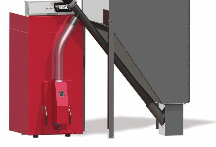
3 Thank You for choosing a ORLIGNO 400 pellet burner from Eko-Vimar Orlanski. We ask you review this operating and installation manual before you start installing your new ORLIGNO 400 pellet boiler in order to avoid harm to people and product. We recommend that the boiler is installed by a licensed plumber. This manual contains information that is protected under copyright law. 1. Delivery ORLIGNO 400 package is packed on one pallet wrapped up with foil. External elements of ORLIGNO 400 are packed in cardbox: - pellet tank with elastic pipe and clamps - auqer with motoreducer - documentation inside of the boiler - cleaning tools are attached to the pallet ORLIGNO 400 boiler Feeder Pellet tank 3


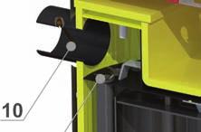


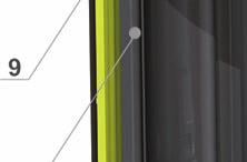


4 2. Boiler view after assembly 1. Boiler controller 2. Pellet tank 3. External auger 4. Feeding pipe 5. Burner 6. Lever for burner cleaning 7. Burner bin 8. Tube exchanger 9. Turbulators 10. Chimney flue 4
5 3. Pellet tank assembly 8 13 Bolt M8 x 1 x 1 x 1 C D D x 3 E B F 2 G 1 1 E C 4 B 3 D D F 3 I H 2 A x 34 M5 x 8 4 Bolt B x 12 M5 x 16 C x 46 M5 D x 18 M8 E x 46 M5 Bolt F x 5 M8 Washer Washer G x 1 H x 1 Nut I x 1 M8 x100 Nut Plug Clamp Bolt 5
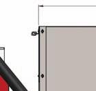
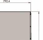
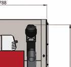

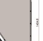
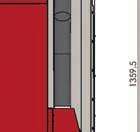
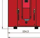
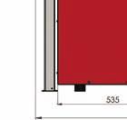
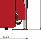
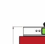
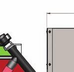
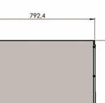
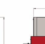
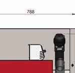
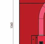
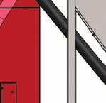

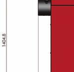

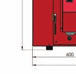
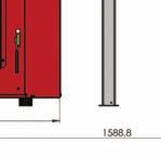
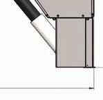
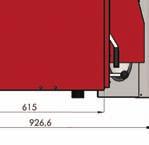
6 4. Dimensions 4.1. ORLIGNO kW 4.2. ORLIGNO kW 6
7 5. Technical data Type unit 16kW 30kW Weight kg 142,5 190 Flue mm Water outlet, return inch 1 1 Efficiency % 89,4 91,8 Power range kw 3,9-16 7,8-30 boiler class EN Required draft Pa min 10 min 10 Max working pressure Bar 2,5 2,5 Water content l Max boiler temp. C Min boiler temp. C Flue gas temp. nominal minimal C Flue gas flow nominal minimal Fuel usage nominal minimal kg/h kg/h 4 0,8 60,1 19,6 7,5 1,5 7


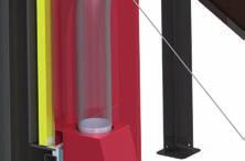
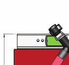
8 6. Orligno 400 package assembly Mounting external equipment: 1. Attach burner plug to the burner socket (pic 1) 2. Assemble fuel tank acc. to enclosed manual. 3. Insert external feeder in to the tank: 4. Attach the elastic pipe between external feeder and the metal connector. Tighten elastic pipe to feeder and metal connector with clamp. 5. Make sure the elastic pipe is near vertical (no bends), so the pellets drop directly into the hearth. 6. Attach the connector from the controller to feeder's motoreducer. 7. Fit the plug 230V to socket from the controller to the 230V socket. 7. Before starting of the burner it is necessary: pic Check installation condition. 2. Fill in pellet to the tank. 3. Check if fuel contains any unwanted elements ( rocks, metal elements). 4. Connect burner's and feeder's plugs. 5. Turn on controller. 6. Feed fuel (SIMPLE MENU: Feed fuel: Yes) from the tank till it shows up on a burner. ATTENTION! Elastic pipe connected between burner and feeder must be under 45 angle so that pellets drops feely to the burner! 7. Turn off fuel feed and hold ON/OFF button - boiler starts automatic lightning up. 8. Fuel characteristics - recommendations a) Pellet granulate made according to DIN granulate 5-8 mm - recommended calorific value kj/kg - ash content 1,5% - max moisture content 12% - density 1-1,4 kg/dm³ 8
, which worsen burning process and may lead to burner s failure. Eko-Vimar Orlański sp. z.o.o. is not responsible for appliance failure or improper burning process when using inappropriate fuel.")
9 ATTENTION! It is recommended to use fuel from reliable sources. Fuel should have appropriate humidity and low content of small fractions. It is necessary pay attention especially to mechanical pollution ( stones), which worsen burning process and may lead to burner s failure. Eko-Vimar Orlański sp. z.o.o. is not responsible for appliance failure or improper burning process when using inappropriate fuel. 9. Cleaning instructions Cleaning should be done regularly and as needed. The boiler should be cleaned weekly to achieve the best efficiency. This ensures the best fuel economy and operation. You increase the cleaning interval if you use the best quality of pellets. Maintenance - chamber cleaning Disconnect burner plug from the burner and take out burner. Clean burning chamber with poker from ashes. 9


10 Maintenance burner cleaning Take out the burner Remove the fixing screw holding basket to the burner Remove burner s basket Clean burner body and basket WARNING! Check permeability of basket holes. Maintenance heat exchanger s cleaning Unscrew upper cover Remove upper cover 10


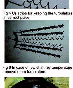
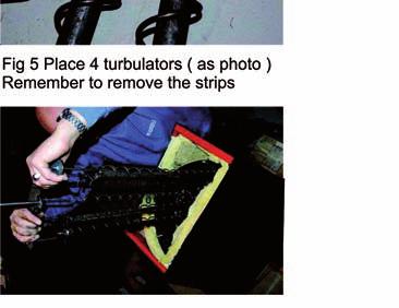
11 Unscrew upper exchanger cover Pull out all turbulators Clean heat exchanger s pipes and turbulators 11


12 WARNING! If boiler is not used for over 14 days it is necessary to empty pellet tank and feeding auger. Cleaning of pellet tank: Occasionally you have to empty the tank completely, in order to clean the area around the feeder inlet from pellet dust. The more dust there is in the tank and around the feeder inlet, may lead to fewer pills in the feeder and the boiler will come out of alignment with the risk of downtime. How often to do tank clean, depends entirely on silo design and the quality of fuel. 12


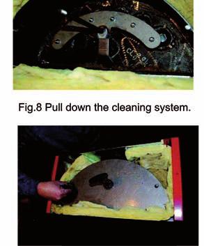
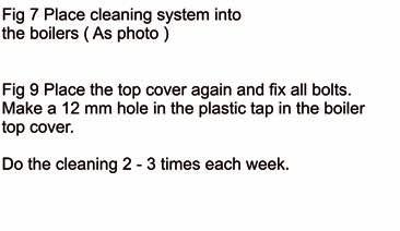
13 ASSEMBLY OF CLEANING MECHANISM - OPTION 13
14 10. Location and package installation Recommended distances to the walls in the boiler room min 500 min

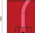
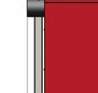
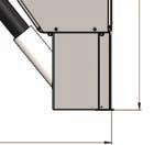
15 10.1. Boiler room recommendation - Package ( boiler, burner, tank, feeder) should be placed in separate room, centrally to heated rooms - Front door should open outside and must be made of nonflammable materials, with 0,8 width - Floor should be made of nonflammable materials or covered with 0,7 mm steel plate at minimum 0,5 m distance to door edges. Boiler should be located on a nonflammable foundation, lifted 0,05 m above floor level - Boiler room should have artificial lightning but natural light is also recommended - Distance to walls in boiler room should allow for easy access to all sides of the boiler - Minimal distance from front side of the boiler to opposite wall should be 1m - Minimal height of the boiler room: at least 2,2 m; in existing building it is allowed 1,9 m with assured supply-exhaust ventilation. - It is forbidden to install boiler and burner in damp rooms or with elevated humidity. Corrosion process may in short time damage the boiler and burner Ventilation - Boiler room should have 200 cm² supply-air duct - Exhaust duct should have at least 14x14 cm section with inlet hole under boiler room ceiling that should lead above roof and be placed near chimney. - Ventilation ducts should be made of nonflammable materials. - It is forbidden to install mechanical ventilation ATTENTION! High risk of carbon monoxide poisoning exists if boiler is located in a room with insufficient access to fresh air Chimney system Chimney draft: If the chimney draft is exceeding 15 Pa, a draft stabilizer should be mounted in the chimney. Warning! By chimney temperatue less than 180 C at rated output, you should be aware that smoke dose not condense in the chimney as it gives soot. At particularly low smoke temperature it may be necessary to put a ceramic or stainless steel sleeve in the chimney. pic. Exemplary boiler connection to stainless steel chimney 15
16 10.4. Safe distance to inflammable substances - During installation and exploitation it is advisable to maintain safe distance of 200 mm from inflammable substances - For inflammable substances with C3 grade of combustibility which rapidly and easy burn (ex. paper, cardboard, wood, plastic) distance is minimum 400 mm; - If combustibility grade is unknown safe distance should be doubled. Combustibility grade of building products A non-burning B - hard burning Building products sandstone, concrete, bricks, fire plaster, Mortar, tile, granite cement board, fiberglass, mineral insulation C1- hard burning beech tree, oak tree, plywood C2 middle burning pine, larch, spruce tree, cork, rubber floor cover C3 easy burning tarmac plywood, celuloids, polyurethane, Polystyrene, polyethylene, plastic User please remember: - Only adult person acquainted with this manual may operate the burner It is forbidden for kids to stay in close distance to burner without presence of adult person. - If inflammable gases penetrate boiler room during activities (varnishing, gluing) it is recommended to turn off the burner. - It is forbidden to use inflammable substances for lightning up the burner, burner will light up automatically. - High risk of fire exist when using open fire or inflammable substances close to installed boiler package. - Burner should be turned off during maintenance (position OFF). - Pay attention on hot burner s surfaces risk of burn. - It is forbidden to lay inflammable items on the burner or nearby. - All defects should be removed at once. - After heating season it is recommended to clean the burner and pellet tank thoroughly. - Oversee the burner during power failure - It is forbidden to manipulate with any electric parts or interfere in burner s construction. 16
17 Controller's manual Contents 11. Connection - electric scheme Overview of the basic functions Control panel The status LED Buttons Graphic display Statuses of furnace Handling Navigation in the menu Starting regulator - ON Switching off the regulator - OFF Time scheduling Service password Simple menu Simple menu screens Main menu Heating Selection of circuit State Settings Time program Service Hot water Selection of circuit State Settings Time program Service Buffer State Settings Time program Service Boiler State Settings Service
18 15.5. Settings Date and time Language General settings Service Burner State Settings Service Alarms Alarm codes Solar State Settings Service Info Expansion of the system - CAN bus Sonda Lambda Solars Specification Ending


 with a neutral (N). WARNING! Wiring must be done with the device disconnected from the power supply.")
19 11. Connection - electric scheme ORLIGNO 400 is equipped in boiler sensor. Boiler sensor is inserted into sleeve in boiler body together with STB thermal protection. Burner contains termic sensor glued to burner body as a burn-back protection. WARNING! External sensors for installation control such as hot domestic water HW1 or central heating CH1 are an option. They are not included in standard ORLIGNO 400 package. The device supply voltage is ~ 230V/50Hz. Plug the power cord to the controller in accordance with the posted signs. Attach to the controller for operating the boiler sensors and actuators as needed. The drawings shows the connection scheme of equipment. In the tables, a description of the inputs and outputs. WARNING! Under no circumstances connect the protective conductor (PE) with a neutral (N). WARNING! Wiring must be done with the device disconnected from the power supply. Connections should be exercised by a person possessing adequate powers in this regard. 19
20 INPUTS Description Tboiler Teg Tburner Thw Troom Tch Tout 12V 5V GND Explanation Boiler temperature sensor Exhaust gas temperature sensor The temperature sensor burner The temperature sensor hot water Room temperature sensor / regulator (CTP) The temperature sensor central heating Outdoor temperature sensor (CTZ) +12V output to supply optional equipment +5V output to supply optional equipment Mass electric to connect sensors OUTPUTS Description Explanation 1 (CH) Central heating circulating pump 2 (HW) Circulating pump for hot water 3 (Ign) Burner igniter 4 (Mo) Opening the central heating mixer 5 (Mc) Closing the central heating mixer 6 (Blo) Burner blower 7 (Ftan) Feeder tank, or if burning wood, it's blower 8 (Fbur) Burner feeder STB Protection STB N Neutral standing N1 Neutral separable such as by STB PE Protective Recommended burner settings in BURNER/SERVICE Type 16kW 30kW air min (20%) air max (100%) feeding max (100%) 4 7,5 photo threshold test fuel mass fuel calorific value 4,5 4,5 fuel start - dose


21 12. Overview of the basic functions Control panel The status LED Status Green light continuously Green blinks Orange light continuously Orange blinks Red light continuously Red blinks Importance Controller OFF Controller enabled, burner OFF Controller enabled, burner enabled Burner works There is an alarm to be confirmed Alarm active 21
22 Buttons Button Function Long press on the main screen (>3 seconds) changes the state of the ON/OFF (on/off). ON / OFF Quick access to the full configuration settings for the central heating. CH Quick access to the full configuration settings for hot water. HW Shows the navigation information and descriptions of the regulated parameters. INFO Back one level up in the menu, the resignation of the parameter change. ESC Up arrow Navigating through the menus, increasing the value of the parameter being edited. On main screen, enter the menu simple. Navigating through the menus, reducing the value of the parameter being edited. On main screen, enter the menu simple. Down arrow ENTER Access to the menu. Acceptance of changes in the value of the parameter being edited. Confirmation of the alarm. 22
23 Graphic display Statuses of furnace Status TURNED OFF CLEANING FIRING UP INCANDESCING POWER 1 POWER 2 MODULATION BURNING OFF Stop Description The burner is not working. Permission to work off. Cleaning the burner by strong stream of air. Firing up fuel. Providing the initial dose of fuel to run igniter and blower. When the flame in phase of the firing up is discovered, starts providing additional portions of fuel and increase the power of blower for arcing furnace. The burner works with the power first. The burner works with the power of a second. The burner works with a modulated power. Quenching of the furnace. Work of burner and blower tray until the complete disappearance of the flame. Burner does not work but it is to agree to his work. The required boiler temperature is reached. 23
24 13. Handling Navigation in the menu The device has two types of menus: simple and main menus. Simple menu allows for quick access to basic controller functions. Enter the menu is simple by pressing the up arrow or down arrow on the main screen. Description of a simple menu in chapter 11. Main menu allows you to access all the functionality of the controller (monitoring, adjustments and service settings.) Access to the main menu is done by pressing the button «Confirm, enter» on the main screen. Description of the main menu in Chapter 11. PBack to the main screen is possible from any screen by pressing the button Back, esc several times. WARNING! Access the service is intended only for qualified technical personnel. The changes may cause malfunction of the system Starting regulator - ON To run the controller (ON mode) for 3 seconds to press the ON / OFF on the screen when it is in the OFF mode Switching off the regulator - OFF To turn off the controller (OFF mode) for 3 seconds to press the ON / OFF on the screen when he is in the ON mode. WARNING! When you turn off the controller, depending on the previous state, the burner can still work (quenching), the state should not be interrupted. If the device is to be excluded from the power supply, wait quenching process, until the status of the burner is off. 24

25 13.4. Time scheduling Controller is equipped with a clock and calendar. This makes it possible to program the operation of individual circuit elements for heating depending on the time and day of week. Date and time are not reset during a power failure, because the controller is equipped with a battery that should be replaced every two years. Programming takes place in the menu of the circuit (eg, hot water, heating, buffer) and for each item carried in the same way. Selecting the day of week. Upon entry in the Programme Time day of the week flashes. Arrow buttons to select the day you want to set or just check the settings of the program. Programming. After selecting the day of week and approved ENTER, indicator being programmed hours flashes. At the same time also displays the time, and the next to it icon that represents the currently selected setting time (the symbol of the sun means comfort temperature, the moon is a symbol of the economic temperature.) To move to the next hour, press the down arrow (economy temperature) or the up arrow (comfort temperature). If the day is already programmed in accordance with our wish, press ENTER. After approved the changes (or cancellation) will blink day of the week. The figure shows an example of the preset day of the week. Temp. economy from 00:00 to 6:00 Temp. comfortable from 6:00 to 9:00 Temp. economy from 9:00 to 18:00 Temp. comfortable from 18:00 to 24:00 WARNING! Values of temperatures comfortable and economical are set in the SETTINGS menu and may be different for each of the circuits. To make the time program work, you must also enable a timed mode in the SETTINGS menu. 25
26 13.5. Service password Access to the service parameters are password protected. After entering the correct password, access will be lifted. Access to the service parameters will be locked after a period of 10 minutes without pushing buttons. Service code is a temperature of the boiler in menu BOILER / SETTINGS and 3 letters EST. Example: If the temperature of the boiler in menu BOILER / SETTINGS is 60 C, password is: 60EST. WARNING! Access the service is intended only for qualified technical personnel. The changes may cause malfunction of the system. 26
 and the")

 and the")


27 14. Simple menu Simple menu screens Screen Description Shows the current temperature of the boiler (large font) and the desired temperature (small font). After pressing the ENTER set the desired temperature of the boiler. Shows the current temperature of hot water (large font) and the desired temperature (small font). After pressing the ENTER set the desired temperature of hot water. Menu relates to the circuit No. 1 Disposable heating hot water to a comfortable temperature regardless of the program. Menu relates to the circuit No. 1 Set the mode a hot water: a. time - according to the programmed timescales b. constatant - regardless of the time intervals comfortable temperature is maintained c. disabled - off the heat Menu relates to the circuit No. 1 27


28 Shows the current temperature in the room No 1 (large font) and the value of the desired (small font). After pressing the ENTER go to set the desired temperature in the room. Menu relates to the circuit No. 1 Set the mode a heating circuit: a. time - according to preset ranges b. constant - regardless of the time intervals comfortable temperature is maintained c. disabled - off the heat Menu relates to the circuit No. 1 Allow for operation of the burner. When not consent to the burner operation, regulator controls the heatingsystem, but do not attach the burner. Manual start of the fuel feed from the tray. Useful function after the exhaustion of fuel from the cartridge. After refilling the fuel cartridge, run the enter fuel until the fuel gets into the burner. 28
29 15. Main menu


30 15.1 Heating Selection of circuit Allows you to select a number of central heating circuit. The selection of the circuit make arrows State Allows you to monitor the status of central heating system. 30
31 Settings Function Comfortable temp. Programme Temp. ekonomiczna Description Desired temperature in the room during the heating. Programs: a. time - according to preset intervals b. constant - regardless of the time intervals comfortable temperature is maintained c. disabled - off the heat d. economic - in the rooms temperature is maintained the economic Desired temperature in the room outside the period of heating Time program Used to configure the time program steering central heating.. Description of the adjustment time program refer to chapter Service WARNING! Access the service is intended only for qualified technical personnel. The changes may cause malfunction of the system. Function Comf. MAX pump temp. Econ. MAX pump temp. MIN Tch pump Source Temperature MAX Mixer time Hot water priority Pump test Mixer test Circ. name Description Maximum outdoor temperature at which the circulating pump can work in a comfortable range. Maximum outdoor temperature at which the circulating pump can work in a economic range. Minimum temperature calculated for central heating at which the circulating pump can be operated. Specifies the source of energy for central heating circuit. Maximum temperature for central heating. Time of full opening of the mixer. Priority for hot water of the heating circuit. During heating hot water the central heating pump is not working. Starts the pump regardless of other conditions. Starts the mixer motor independently of the other conditions. Gives name for the central heating circuit. 31
32 Function CH temp. for -20 C CH temp. for 0 C CH temp. for 10 C Description The point of the heating curve for -20 C. The point of the heating curve for 0 C. The point of the heating curve at 10 C. Service CH temp. for corr. factor Mode type Manual Tch Room temp. sensor CH temp. sensor Permanent pump Central heating temperature correction required the desired room temperature for 1 º C. For example, if the correction factor is set at 6 C, room temperature set at 20 C and measured in the room is 20.5 C then the temperature calculated at will be reduced by 3 C. Specifies the input mode central heating temperature: manual - the temperature of central heating inflicted manually, weather - the temperature of central heating calculated from the heating curve. The desired temperature of central heating when the mode is set to manual. Specifies whether the system uses a room sensor. Specifies whether the system uses a sensor heating. Yes - the pump runs at a given temperature in the room, reduced the temperature for heating (only with the use of a sensor for central heating and room sensor), No - after reaching the set temperature in the room the pump is turned off. 32


33 15.2 Hot water Selection of circuit Allows you to select the number of hot water circuit State Allows you to monitor the status of hot water. 33
34 Settings Function Comfortable temp. Programme Heat now Hysteresis Economical temp. Description Desired temperature of hot water during heating. Set the mode a circuit: a. time - according to preset ranges b. constant - regardless of the time intervals comfortable temperature is maintained c. disabled - off the heat. Heats hot water once to a comfortable temperature regardless of the program. The value of which can reduce the temperature of hot water. Desired temperature of hot water outside the period of heating Time program Used to configure the time steering hot water preparation. Description of the adjustment time refer to chapter Service WARNING! Access the service is intended only for qualified technical personnel. The changes may cause malfunction of the system. Source delta Source Function Description Increasing the temperature of the source of the desired temperature of hot water during heating. Specifies the source of energy for hot water. Temperature MAX Delta MIN temp. Pump test Circ. name Maximum temperature of hot water. The minimum temperature difference between the source and the hot water at which the pump can work. Starts the pump regardless of other conditions. Gives name for the hot water circuit. 34


35 15.3 Buffer (option available only with external module CAN) State Settings Function Upper set temperature Lower set temperature Programme Description Below this temperature in the upper part of the buffer starts charging. Above this temperature at the bottom of a buffer completes the process of charging. Constant - the buffer is charged regardless of the time, time - the buffer charged only at specified intervals. Intervals are set in the time program, disabled - off charging buffer Time program Used to configure time program to controlling charging buffer. Description of program adjustment time refer to chapter Service WARNING! Access the service is intended only for qualified technical personnel. The changes may cause malfunction of the system. 35
 is requested manually or automatically. Automatically based on the needs of other power consumers in the buffer. 15.4")

36 Function Minimal pump temp. Auto upper temp. Description The minimum temperature in the upper part of the buffer at which the circulating pump can work for central heating. Specifies whether the upper temperature buffer (minimum) is requested manually or automatically. Automatically based on the needs of other power consumers in the buffer Boiler State Statistics of the boiler in the past 24 hours. The graph shows the temperature of the boiler and power of burner. Hours refers to how many hours ago the boiler behaved these operating parameters. Across the screen are displayed statistics of 2 hours. Screens switching buttons up and down Settings Boiler temp. set Function Description Heating water temperature in the boiler which will be maintain the controller. Menu is active only in continuous work mode Service WARNING! Access the service is intended only for qualified technical personnel. The changes may cause malfunction of the system. 36

37 Function MIN pump temp. Mode Hysteresis MIN return temp. Return mixer time Boiler pump test Return mixer test Description The temperature above which the the controller can attach pumps. Operating mode of boiler: a. auto - temperature calculated automatically b. continuous - the temperature is kept constant The temperature of the boiler must be reduced by this value to launch the burner. Minimal return to boiler temperature maintain by mixer. Specifies the time of full opening of the return mixer. Starts boiler pump regardless of other conditions. Starts actuator of the return mixer regardless of other conditions Settings Date and time Using this menu is made to set the date and time of the driver Language Use this menu to select language of the menu General settings Alarm buzzer We define here, if the driver shall notify of alarms by acoustic signal Service WARNING! Access the service is intended only for qualified technical personnel. The changes may cause malfunction of the system. 37
38 Module configuration Menu is used to configure the CAN network. In the menu, select the modules that are connected to the system. WARNING! A detailed description of the modules and their destination are described in the manual of expansion modules. SUMMARY OF THE EXPANSION MODULES Module Description Module no. 0 3 heating circuits of the numbers 2,3,4. Outdoor temperature sensor. Module no. 1 3 heating circuits of the numbers 5,6,7. Module no.2 3 heating circuits of the numbers 8,9,10. Module no 3 3 heating circuits of the numbers 11,12,13. Module no 4 3 heating circuits of the numbers 14,15,16.. Buffer. Module no 5 Module no 6 Module no 7 Module Lambda Solar collectors. Hot water no. 2. Return temperature sensor. Not used. Not used. Module of the Lambda sensor. 38

. Specifies if in the system is installed return temperature sensor (module 5).")
39 System configuration Menu is used to configure the heating system (hydraulic). The possibility of settings is dependent of number of expansion modules connected in the system. WARNING! You must first configure the modules.. SYSTEM CONFIGURATION Function Number of CH circuits Number of HW circuits Number of buffers Outside temp. sensor Return temp. sensor Solars Description Specifies the number of heating circuits in the system. Specifies the number of hot water circuits in the system. Specifies the number of buffors in the system. Specifies if in the system is installed outside temperature sensor (module 0). Specifies if in the system is installed return temperature sensor (module 5). Specifies if the system is equipped with solar collectors Restore to factory settings This function allows the controller to restore the factory settings. WARNING! Will be restored all factory settings, which can cause your system to malfunction. After restoring the factory settings may be need to reconfigure the controller settings Burner State 39
40 Settings Function Description Feed fuel now Burner on Fuel type Starts fuel feeding screw regardless of other features. Consent to work of the burner. Specifies the type of fuel Service WARNING! Access the service is intended only for qualified technical personnel. The changes may cause malfunction of the system. Function Air MIN (20%) Air MAX (100%) Feeding MAX (100%) Power MIN (FL2) Power MAX (FL2) Modulation type Photo threshold Igniter test* Heater feeder test* Storage feeder test* Description Minimum amount of air during modulation where power of burner is 20% or power number is 1. Maximum amount of air during modulation where power of burner is 100% or power number is 2. Maximum time during fuel feeding when power of modulation is 100% or power number is 2 on every 20 seconds. Minimal burner power during modulation. Maximal burner power during modulation. Burner mode, power modulation or two power levels. Brightness in the the burner over which is recognized as a fire. Turn on igniter for testing. Turn on burner feeder for testing. Turn on storage feeder for testing. Blower test* Turn on blower for testing. Test fuel mass Fuel mass obtained during continuous fuel feeder work through 1 hour (in kg). Fuel calorific value Fuel calorific value (in kwh/kg). Lambda control Oxygen MIN (20%) Oxygen MAX (100%) Fuel start dose Determine whether regulator consider or not oxygen concentration. Oxygen target for minimal power. Oxygen target for maximal power. Feeding time in order to iqnite fuel. * testing equipment in the menu BURNER is only possible when the controller is in the OFF mode. 40

41 15.7 Alarms This menu contains a history of up to 20 alarms that occurred during the controller work. The importance of alarm codes was presented in table below Alarm codes CODE Short description Explanation 1 Processor overheating Procesor overheating. The reason may be improper installation location of the controller. 2 No fire / fuel The controller detected a lack of flame in the burner. The reason could be the end of the fuel or the flame goes out. 3 Burner overheating The temperature of the burner has reached its maximum value!ą! 4 Boiler sensor shorted The controller detected shorted boiler temperature sensor. The reason may be damaged sensor or connection cable. 5 Boiler sensor open The controller detected open boiler temperature sensor. The reason may be damaged sensor or connection cable. 6 Burner sensor shorted The controller detected shorted burner temperature sensor. The reason may be damaged sensor or connection cable. 7 Burner sensor open The controller detected open burner temperature sensor. The reason may be damaged sensor or connection cable. 8 Boiler overheating Boiler temperature has exceeded the maximum value! 9 Processor reset Probable damage the controller! Possible to loss of power supply. 10 STB 11 Communication with module 0 12 Communication with module 1 13 Communication with module 2 14 Communication with module 3 15 Communication with module 4 16 Communication with module 5 17 Communication with module 6 18 Communication with module 7 19 HW sensor shorted 41
42 CODE Short description Explanation 20 HW sensor open 21 Room temp. sensor shorted 22 Room temp. sensor shorted 23 Quenching error 24 Lambda communication 25 Solars overheating 26 Solars freezing The codes of the modules 33 Shorted IN1 Module 0 34 Shorted IN2 Module 0 35 Shortede IN3 Module 0 36 Shorted IN4 Module 0 37 Shorted IN5 Module 0 38 Shorted IN6 Module Zwarcie IN11 Module Open IN1 Module 0 46 Open IN2 Module 0 47 Open IN3 Module 0 48 Open IN4 Module0 49 Open IN5 Module 0 50 Open IN6 Module Open IN11 Module Overheating Module 0 42
43 CODE Short description Explanation 65 Shorted IN1 Module 1 66 Shorted IN2 Module1 67 Shorted IN3 Module 1 68 Shorted IN4 Module 1 69 Shorted IN5 Module 1 70 Shorted IN6 Module Open IN1 Module1 78 Open IN2 Module 1 79 Open IN3 Module 1 80 Open IN4 Module 1 81 Open IN5 Module 1 82 Open IN6 Module Overheating Module 1 97 Shorted IN1 Module 2 98 Shorted IN2 Module 2 99 Shorted IN3 Module ShortedIN4 Module2 101 Shorted IN5 Module Shorted IN6 Module
44 CODE Short description Explanation Open IN1 Module Open IN2 Module Open IN3 Module Open IN4 Module Open IN5 Module Open IN6 Module Overheating Module Shorted IN1 Module Shorted IN2 Module Shorted IN3 Module Shorted IN4 Module Shorted IN5 Module Shorted IN6 Module Open IN1 Module Open IN2 Module Open IN3 Module 3 44
45 CODE Short description Explanation 144 Open IN4 Module Open IN5 Module Open IN6 Module Overheating Module Shorted IN1 Module Shorted IN2 Module Shorted IN3 Module Shorted IN4 Module Shorted IN5 Module Shorted IN6 Module Open IN1 Module Open IN2 Module Open IN3 Module Open IN4 Module Open IN5 Module Open IN6 Module
46 CODE Short description Explanation Overheating Module Shorted IN1 Module Shorted IN2 Module5 195 Shorted IN3 Module5 196 Shorted IN4 Module Shorted IN6 Module Shorted IN7 Module Shorted IN8 Module Shorted IN9 Module Overheating Module 5 46


]. Over this hot water temp. solar pump is turn off. Maximal temp. of solar collector.")
47 15.8 Solar (option available only with external module CAN) State Settings Function Description Turn on delta Turn off delta Temp. difference between solar and accumulator needed for solar pump turn on. Temp. difference between solar and accumulator needed for solar pump turn off Service Function Description Schematic Flow [l/min] Fluid specific heat MAX HW temp. Solar alarm temp. MAX Solar alarm temp MIN Solar pump test Solar system schematic. Heating fluid flow in l/min. Specific heat of heat-transfer fluid [kj/ (kg*k)]. Over this hot water temp. solar pump is turn off. Maximal temp. of solar collector. Alarm and damage preservation procedure are taken over this temp. Minimal temp. of solar collector. Alarm and antifreeze procedure are taken under this temp. Allow for solar pump testing. 47


48 15.9 Info There you will find useful information about the controller, including the version of software. 16. Expansion of the system - CAN bus The controller is equipped with a high bandwidth CAN bus used to communicate with the modules. Thanks to the well-known for their reliability, widely used in automotive bus system is expandable to the highest level. Use of CAN bus carries several advantages. Gain above all the possibility of using broadband Lambda oxygen sensor and the using additional of expansion modules rozszerzeniowych I / O we can install throughout the system: to 16 are heating circuits, 2 circuits of hot water, heat storage tank (buffer), solar system (solars). 48
49 Socket CAN bus is on the left side of the device. Connecting cable must be connected according to the following designation. Cable connection: L line LOW (white) H line HIGH (brown) GND ground (grey) For connections on the CAN bus should be only used cable LiYCY 2x0,25. Only this type of cable gives the proper work of devices. Connections perform in a serial manner, this represents a figure below. Plugging in expansion modules you need to remember to correctly set the terminator, which should be attached only at the last module throughout the system, even if the module is the only one. After performing all the connections you must configure the module settings. Make this by selecting the modules that are connected to the network. More about the configuration each of expansion modules can be found in chapter and instruction of the enlargement module I/O. After finishing configuration of expansion modules to do remains only a change the system settings. Menu is used to configuration the heating system and the possibility of settings is dependent of number of arranged expansion modules. The table describing the functions refer to chapter On the next page is a sample diagram of the system. Please Warning that this is only overhead view, not containing all the elements of the system. 49
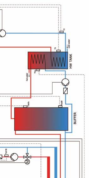
50 50
51 16.1 Sonda Lambda Lambda sensor we can connect to the system in two ways: directly to the controller, if the entire system with CAN bus module will only use Lambda oxygen sensor, through enlargement module I/O with the number 5, if in the system there are other modules enlargement. After connecting the module configure the controller yet. For this purpose, proceed as explained below. From the main menu select SETTINGS Then in the mode SERVICE enter the access code After inputting the correct code, run the MODULES CONFIGURATION 51


52 Find Lambda Module and turn it on by changing the option to YES At this point, turned on the module Lambda. The second step is a change the configuration settings for the burner. From the main menu by selecting BURNER we get to the settings. Here you can again enter the mode SERVICE and if required, enter the access code. In the list, you can locate the position Lambda control, which switches on YES. It is also possible working with switched off Lambda control mode. Then Lambda oxygen sensor module will be responsible only for displaying the measurements. 52


53 16.2 Solars Solar collectors are supported only by enlargement module I/O number 5th. After performing all the connections you must configure the controller to work with collectors proceed as described below. The first step is to enable module number 5. From the main menu select SETTINGS Then in the mode SERVICE enter the access code After inputting the correct code, run the MODULES CONFIGURATION Find Module 5 and activate it by changing the settings to YES Now enable the solar handling. As the main menu select SETTINGS and then enter the access code in the SERVICE mode 53

54 Now enable the solar handling. As the main menu select SETTINGS and then enter the access code in the SERVICE mode After entering the code run SYSTEM CONFIGURATION Find the position Solars and activate them by changing the settings to YES After finishing configuration the controller we can start to change the adjustment and settings for Solars. Description of the configuration these elements can be found in chapter
55 17. Specification Technical data Module supply voltage ~230V/50Hz ±10% Power input (module) <6VA Temperature measurement accuracy ±4ºC NTC 10kΩ B25/85=3877K±0,75% Sensors VISHAY BC components Ambient temperature 0-60 C Moisture 5-95% non-condensing Software class A Module output load capacity CH pump 100W HW pump 100W Igniter 400W Blower 150W Burner feeder 150W Feeder tank 150W 18. Ending Present appliance is marked according to European Directive 2002/96/EC on waste electrical and electronic equipment. Symbol placed on the components or attached documents means that appliance is not classified as a household waste. Scrapping should take place in special collection point in order to reuse electrical and electronic components. 55


56 EKO-VIMAR ORLAŃSKI Sp. z o.o Otmuchów, ul. Nyska 17b POLSKA / woj. opolskie T , F , E biuro@orlanski.pl IO_ORLIGNO_400_ _EN
INSTRUCTION MANUAL & SERVICE MANUAL ORLIGNO 400
 INSTRUCTION MANUAL & SERVICE MANUAL ORLIGNO 400 Content 1. Delivery...3 2. Installation and assembly...3 3. Boiler view after assembly...6 4. Pellet tank assembly...7 5. Dimensions...8 5.2. ORLIGNO 400
INSTRUCTION MANUAL & SERVICE MANUAL ORLIGNO 400
 INSTRUCTION MANUAL & SERVICE MANUAL ORLIGNO 400 Content 1. Delivery......................................................................... 3 2. Installation and assembly.........................................................
BOILER CONTROLLER COMPACT
 BOILER CONTROLLER COMPACT page 2 Index Index 1 General information 5 1.1 Introduction 5 1.2 Features 5 1.3 Safety precautions 7 1.4 Disposal of old equipment 8 2 Connecting to the system 9 2.1 General
MANUAL AND SERVICE MANUAL ORLIGNO 100
 MANUAL AND SERVICE MANUAL ORLIGNO 100 Content 1. Boiler application...3 2. Installation...4 2.1. Ventilation...4 2.2. Supply-air ventilation...4 2.3. Exhaust ventilation...4 2.4. Chimney connection...4
PELLETS BURNER 15-60kW MOC
 PELLETS BURNER 15-60kW MOC. Please read those documentation before first start up the unit. Improper burner start may lead to its damage and may create a danger for end user! Table of Contents: 1. Admission
Eco Angus Wood Pellet Boilers
 Eco Angus Wood Pellet Boilers ISO 9001 ISO 14001 1 Contents 3 Our product philosophy 3 Our approach 3 Manufacturing credentials 4 Orligno 400 4 Boiler construction 5 Boiler description 5 Burner 6 Technical
INSTRUCTION MANUAL & SERVICE MANUAL ORLIGNO 500
 INSTRUCTION MANUAL & SERVICE MANUAL ORLIGNO 500 MANUAL INSTRUCTION CONTENTS 1. Boiler application...3 2. Description of the controller...3 2.1. Lightning up...........................................................
PELLUX INSTALLATION AND MAINTENANCE INSTRUCTIONS PELLUX 100 H AP
 MOS GB 1411-1 331139 INSTALLATION AND MAINTENANCE INSTRUCTIONS H AP Table of Contents For Home Owners General System description Area of use 3 Product description 3 Heating 3 Hot water heating 3 System
Operating manual. Pellet boiler. Orlan Pellet ISO 9001
 Operating manual Pellet boiler Orlan Pellet ISO 9001 Contens 1. Boiler s use...................................................................... 3 2. Boiler s way of working...........................................................
PELLUX 100/20 PELLUX 100/30
 24/02/2015 24148 INSTALLATION & OPERATING MANUAL PELLUX 100/20 PELLUX 100/30 AP H To Users Information for the User Information for the User We recommend the following steps after the consumption of 300
INSTALLATION AND MAINTENANCE INSTRUCTIONS PELLUX PELLUX 100 H AP
 MOS GB 1248-1 231259 INSTALLATION AND MAINTENANCE INSTRUCTIONS H AP Table of Contents For Home Owners General System description Area of use 3 Product description 3 Heating 3 Hot water heating 3 System
ISO 9001 TUV CERT CE
 ISO 9001 TUV CERT CE INSTRUCTION MANUAL CONTENT 2 1. Boiler application 2. Principle of work 3. Description of the controller 3.1. Front panel of EKOSTER 2 3.2. Main functions of EKOSTER 2 4. Gasification
natural warmth of the house A compact boiler designed to combust ecological fuel- pellet ORLIGNO 500 Compliant with EN norm
 natural warmth of the house A compact boiler designed to combust ecological fuel- pellet ORLIGNO 500 Compliant with EN 330-5 norm Biomass - the curse of energetics or the only fuel of the future? The real
Electronic Pellet Burner Controller NPBC-V3-1
 Electronic Pellet Burner Controller NPBC-V3- SOFTWARE VERSION 3.2/3. page of 3 CHANGES IN THE TECHNICAL AND USER GUIDE OR IN THE SOFTWARE VERSION Technical and User Guide's version Changes Page 2.8. The
OPERATION MANUAL RK-2006LPP AUGER FITTED SOLID FUEL BOILER TEMPERATURE CONTROLLER. Version DC19
 OPERATION MANUAL RK-2006LPP AUGER FITTED SOLID FUEL BOILER TEMPERATURE CONTROLLER Version DC19 1. Application. Controller RK-2006LPP is designed for temperature control of solid fuel fired water boilers
NEW LINE BOILER CONTROLLERS
 BOILER CONTROLLERS IGNEO NEW LINE BOILER CONTROLLERS We are pleased to present a new versatile line of boiler controllers from IGNEO with new unprecedented capabilities. The IGNEO family of controllers
Electronic Pellet Burner Controller NPBC-V3M
 Electronic Pellet Burner Controller NPBC-V3M SOFTWARE VERSION 3.3a/3.2 page of 27 CHANGES IN THE USER MANUAL OR IN THE CONTROLLER'S SOFTWARE Version of the user manual Changes Page 2.2. The software version
PELMAX HEATING BOILER FOR SOLID FUEL
 PELMAX HEATING BOILER FOR SOLID FUEL INSTALLATION, SERVICE AND MAINTENANCE MANUAL OF THE BOILER Member of the NIBE Group 21683 Issue 06.2012 Changes reserved Installation, service and maintenance manual
Heating, Air Conditioning, Ventilation. Отопление-Кондиционеры-Вентиляция. MTM 8-30 kw UNIVERSAL OIL HEATER OPERATING MANUAL
 Heating, Air Conditioning, Ventilation Отопление-Кондиционеры-Вентиляция MTM 8-30 kw UNIVERSAL OIL HEATER OPERATING MANUAL 1. Usage MTM 8-30 universal oil heater is designed for heating commercial rooms
GH10PA USER MANUAL. Program version 01 MANUAL FOR CONTROLLER FOR CONTROLLING CENTRAL HEATING BOILERS FIRED WITH PELLETS AND OATS
 MANUAL FOR CONTROLLER GH10PA FOR CONTROLLING CENTRAL HEATING BOILERS FIRED WITH PELLETS AND OATS Program version 01 USER MANUAL We request that users carefully study applicable Instructions before connecting
PELLET BURNER PV 350
 PELLET BURNER PV 350 INSTRUCTION MANUAL v1.1 1 PRODUCT DESCRIPTION...3 2 SAFETY RULES...3 3 WARNINGS...4 4 INSTALLATION INSTRUCTIONS...5 4.1 BOILER REQUIREMENTS...5 4.2 PELLET CONTAINER...6 4.3 INSTALLATION
INSTRUCTIONS FOR USE OF COMBINED BOILER INTENDED FOR COMBUSTION OF BOTH PELLETS AND SOLID FUEL ABC COMBO
 INSTRUCTIONS FOR USE OF COMBINED BOILER INTENDED FOR COMBUSTION OF BOTH PELLETS AND SOLID FUEL ABC COMBO .Technical specifications Boiler power DESCRIPTION Water content in a boiler Required draft Supply
Operation and maintenance manual for the. KSP Spark. series boilers equipped with feeders
 Operation and maintenance manual for the KSP Spark series boilers equipped with feeders Thank you for purchasing PEREKO heating boiler. This documentation applies to the KSP Pelet boilers with fuel feeder
ecomax 200 W Boiler regulator FOR SOLID FUEL BOILERS WITH A FAN OPERATION AND MAINTENANCE MANUAL ISSUE:
 Boiler regulator ecomax 200 W FOR SOLID FUEL BOILERS WITH A FAN OPERATION AND MAINTENANCE MANUAL ISSUE: 1.3 APPLICABLE TO SOFTWARE 10.034 10.035 10.036 2010-04-14 TABLE OF CONTENTS 1 Safety... 4 2 General
INSTRUCTION MANUAL & SERVICE MANUAL ORLIGNO 200
 INSTRUCTION MANUAL & SERVICE MANUAL ORLIGNO 200 CE INSTRUCTION MANUAL Content 1. Boiler application...3 2. Principle of work...3 3. Description of the controller...4 3.1. Front panel of EKOSTER 2...4 3.2.
INSTRUCTION MANUAL & SERVICE MANUAL ORLAN 96 SUPER ORLAN 130 SUPER
 INSTRUCTION MANUAL & SERVICE MANUAL ORLAN 96 SUPER ORLAN 130 SUPER INSTRUCTION MANUAL Content 1. Boiler application...3 2. Principle of work...3 3. Description of the controller...4 3.1. Front panel of
INSTRUCTION FOR THE USER THC V E OIL BLU
 INSTRUCTION FOR THE THC V E OIL BLU CONTENTS General safety information 4 Precautions 4 Control panel 5 Mode selection 8 User levels 10 Start-up 12 Temporary shutdown 15 Preparing for extended periods
USER MANUAL 9kW LILLY PELLET STOVE
 USER MANUAL 9kW LILLY PELLET STOVE Table of Contents.Overview of Stove Parts... 2.Technical Characteristics... 3 3.Important Information... 4 4.Pellet Specification...5 5.Technology... 6 6.Installation...
USE AND MAINTENANCE. Cm Pelet-set (60-90 kw) TECHNICAL INSTRUCTIONS
 TECHNICAL INSTRUCTIONS") CENTROMETAL d.o.o. Glavna 12 40306 Macinec Croatia tel: +385 40 372 600; fax : +385 40 372 611 TECHNICAL INSTRUCTIONS USE AND MAINTENANCE Cm Pelet-set (60-90 kw) For boilers: EKO-CK P 70-110 TUPS-90K-09-2015-E-N-eng
CENTROMETAL d.o.o. Glavna 12 40306 Macinec Croatia tel: +385 40 372 600; fax : +385 40 372 611 TECHNICAL INSTRUCTIONS USE AND MAINTENANCE Cm Pelet-set (60-90 kw) For boilers: EKO-CK P 70-110 TUPS-90K-09-2015-E-N-eng
Service Manual. Unit: Pellet burner. Type: ROT-POWER. Models: kw, kw
 Service Manual Unit: Pellet burner Type: ROT-POWER Models: 15-70 kw, 20-100 kw BTI GUMKOWSKI Sp. z o.o. Sp. k. ul. Obornicka 71, 62-002Suchy Las Phone +48 606-936-692, +48 61-811-70-37 biuro@kipi.pl update:
TECHNICAL AND OPERATIONAL DOCUMENTATION
 METAL AND BOILER FACTORY 28-100 Busko-Zdrój, Owczary, ul Przemysłowa 3 Tel No +4841 378 46 19, fax +4841 370 83 10 TECHNICAL AND OPERATIONAL DOCUMENTATION SAS MULTI FLAME BURNER ADAPTED FOR BURNING OF
TECHNICAL INSTRUCTIONS USE AND MAINTENANCE
 TECHNICAL INSTRUCTIONS USE AND MAINTENANCE Cm Pelet-set For boilers CentroPlus 25/35 and CentroPlus-B 25/35 (solid fuel and wood pellets fuel firing) TUPSCP-K-11-2016-ENG CONTENTS 1.Introduction 2. Status
SWEBO Bioenergy Manual pellet burner PB50 Rev no. Date Page PBM1: (37) Installation and maintenance instructions
 Installation and maintenance instructions") PBM1:12 2008-10-16 1 (37) Installation and maintenance instructions PBM1:12 2008-10-16 2 (37) TABLE OF CONTENTS 1 GENERAL INFORMATION... 5 1.1 PELLET STORAGE... 6 1.2 CONSTRUCTION AND FUNCTION... 7 1.2.1
PBM1:12 2008-10-16 1 (37) Installation and maintenance instructions PBM1:12 2008-10-16 2 (37) TABLE OF CONTENTS 1 GENERAL INFORMATION... 5 1.1 PELLET STORAGE... 6 1.2 CONSTRUCTION AND FUNCTION... 7 1.2.1
Pellet burner PV 180a. User manual
 Pellet burner User manual Table of content Table of content...2 Description...5 Fuel...7 Installation...7 Boiler requirements...8 Pellet container...11 Burner...12 External auger...20 Electrical connections...21
USERS MANUAL FOR GAS BOILERS
 USERS MANUAL FOR GAS BOILERS PLEASE READ THE MANUAL CAREFULLY: IT CONTAINS IMPORTANT INFORMATION REGARDING SAFETY, INSTALLATION, USE AND MAINTENANCE OF THE APPLIANCE MODELS: NOVADENS 24 NOVADENS 24C NOVADENS
USE AND MAINTENANCE. Cm Pelet-set TECHNICAL INSTRUCTIONS. (14-35 kw) For boilers: EKO-CK P (EKO-CK 20-40) EKO-CKB P (EKO-CKB 20-40)
 For boilers: EKO-CK P (EKO-CK 20-40) EKO-CKB P (EKO-CKB 20-40)") TECHNICAL INSTRUCTIONS USE AND MAINTENANCE Cm Pelet-set (14-35 kw) For boilers: EKO-CK P 20-40 (EKO-CK 20-40) EKO-CKB P 20-40 (EKO-CKB 20-40) TUPS-K-02-2011-E-N-ENG CONTENTS 1. Introduction....... 2. Status
TECHNICAL INSTRUCTIONS USE AND MAINTENANCE Cm Pelet-set (14-35 kw) For boilers: EKO-CK P 20-40 (EKO-CK 20-40) EKO-CKB P 20-40 (EKO-CKB 20-40) TUPS-K-02-2011-E-N-ENG CONTENTS 1. Introduction....... 2. Status
Declaration of Conformity No. 27/2008
 ST-44 USER S MANUAL ST-45 User's Manual Declaration of Conformity No. 27/2008 Hereby, we declare under sole responsibility that the ST-45 230V 50Hz thermoregulator manufactured by TECH, ul. St. Batorego
1 DOCUMENT REVISION CONTROL ELEMENTS... 9
 CONTENTS Contents 1 DOCUMENT REVISION... 8 2 SOFTWARE VERSION... 8 3 BASIC DESCRIPTION... 8 4 CONTROL ELEMENTS... 9 4.1 BASIC DISPLAYS...10 4.2 CONTROL KEYS...11 4.2.1 Rotary button (Press / Turn)...11
Unit: Pellet burner Type: ROT-POWER
 Service Manual Unit: Pellet burner Type: ROT-POWER Models: 4-16 kw, 5-20 kw, 6-26 kw, 8-36 kw, 10-50 kw. BTI GUMKOWSKI Sp. z o.o. Sp.k. ul. Obornicka 71, 62-002Suchy Las Tel. +48 606-936-692, +48 61-811-70-37
ST 53.1 User s manual
 Tech - 1 - ST 53.1 User s manual Table of contents I. Safety... 3 II. Description... 4 III. Installation... 4 IV. Operating the Controller... 6 IV.a) Principle of Operation... 6 IV.b) Control... 6 V. Controller
Pellet burner PELETIX II+ Operating and assembly manual VER_EN_2.0_2015
 Pellet burner EN PELETIX II+ Operating and assembly manual VER_EN_2.0_2015 5. Installation... 8 Table of content 1. Introduction... 3 2. Safety... 3 2.1. Regulations and standards... 3 2.2. Precautions
BIX B-One 100 kw INSTALLATION GUIDE
 BIX B-One 100 kw INSTALLATION GUIDE Dear Customer, We thank you for choosing our product. The Bix B-One 100 Kw is a burner of advanced concept and technology, with a high reliability and construction quality.
Room panel. for ecomax800 R or T regulators. OPERATION AND MAINTENANCE MANUAL ISSUE: 1.3 APPLICABLE TO SOFTWARE: v , v , v08.21.
 Room panel ecoster 200 for ecomax800 R or T regulators OPERATION AND MAINTENANCE MANUAL ISSUE: 1.3 APPLICABLE TO SOFTWARE: v08.21.014, v08.21.015, v08.21.016 2010-08-31 TABLE OF CONTENTS 1. SAFETY...
TECHNICAL AND MAINTENANCE DOCUMENTATION OPERATION AND MAINTENANCE MANUAL WARRANTY
 Pellet Comfort water boiler with nominal heat capacity of: 7, 10, 16 and 25 kw with automatic solid fuel feeding, using pellet. Page 1 TECHNICAL AND MAINTENANCE DOCUMENTATION OPERATION AND MAINTENANCE
ARITERM OY. Arimatic 500. User manual
 ARITERM OY Arimatic 500 User manual Table of contents 1. General information... 3 2. Transport, storage and package opening... 3 3. Warranty... 3 4. Installation and commissioning... 4 5. System description...
STILE BEAUTY AND TECHNOLOGY
 STILE BEAUTY AND TECHNOLOGY STILE, in line with your style Designer White Bordeaux Silver Grey MODEL Nominal input kw Nominal output kw Output to the water min. / max. kw HYDRONIC PELLET FIRE SPACE HEATING
REGULATOR TIS TRONIC 496P
 REGULATOR TIS TRONIC 496P FOR SOLID FUEL ATOMATIC BOILERS WITH THE LIGHTER TIS TRONIC 297* TIS TRONIC 281* TIS TRONIC 501* econet.apk www.econet24.com functions available for an additional module TIS TRONIC
Cm Pelet-set TECHNICAL INSTRUCTIONS FOR THE COMMISSIONING AND ADJUSTMENT. (14-35 kw) For boilers: EKO-CKB P (EKO-CKB 20-40)
 For boilers: EKO-CKB P (EKO-CKB 20-40)") TECHNICAL INSTRUCTIONS FOR THE COMMISSIONING AND ADJUSTMENT Cm Pelet-set (14-35 kw) For boilers: EKO-CK P 20-40 (EKO-CK 20-40) EKO-CKB P 20-40 (EKO-CKB 20-40) TUPS-M-11-2015-E-N-ENG CONTENTS 1. Introduction.....
TECHNICAL INSTRUCTIONS FOR THE COMMISSIONING AND ADJUSTMENT Cm Pelet-set (14-35 kw) For boilers: EKO-CK P 20-40 (EKO-CK 20-40) EKO-CKB P 20-40 (EKO-CKB 20-40) TUPS-M-11-2015-E-N-ENG CONTENTS 1. Introduction.....
Cm Pelet-set (60-90 kw)
") CENTROMETAL d.o.o. Glavna 12 40306 Macinec Croatia tel: +385 40 372 600; fax : +385 40 372 611 TECHNICAL INSTRUCTIONS FOR THE COMMISSIONING AND ADJUSTMENT Cm Pelet-set (60-90 kw) For boilers: EKO-CK P
CENTROMETAL d.o.o. Glavna 12 40306 Macinec Croatia tel: +385 40 372 600; fax : +385 40 372 611 TECHNICAL INSTRUCTIONS FOR THE COMMISSIONING AND ADJUSTMENT Cm Pelet-set (60-90 kw) For boilers: EKO-CK P
SOLID FUEL HEATING UNIT TYPES NPS 35 AND NPS 70 ORIGINAL INSTRUCTION MANUAL
 SOLID FUEL HEATING UNIT TYPES NPS 35 AND NPS 70 ORIGINAL INSTRUCTION MANUAL 1. General information The Original Instruction Manual constitutes an integral and material part of the product, and is to be
PER-EKO type KSW & KSW PLUS Instruction Manual
 TABLE OF CONTENTS INTRODUCTION..... 3 1. GENERAL INFORMATION..... 3 1.1. Application.. 3 1.2. Fuel..... 3 1.3. Dimensions & technical parameters........ 4 2. BOILER TECHNICAL SPECIFICATION...... 4 2.1.
Electronic pellet burner controller - NPBC-V3M. Electronic Pellet Burner Controller NPBC-V3M
 Electronic Pellet Burner Controller NPBC-V3M page 1 of 11 INTRODUCTION NPBC-V3M is an advanced, functionally completed controller for pellet burners. All the mechanisms and sensors of the burner, as well
SWEBO Bioenergy Manual pellet burner PB20 Rev no. Date Page PBM1: (36) Installation and maintenance instructions
 Installation and maintenance instructions") PBM1:12 2018-01-22 1 (36) Installation and maintenance instructions PBM1:12 2018-01-22 2 (36) TABLE OF CONTENTS 1 GENERAL INFORMATION... 5 1.1 PELLET STORAGE... 5 1.2 CONSTRUCTION AND FUNCTION... 6 1.2.1
PBM1:12 2018-01-22 1 (36) Installation and maintenance instructions PBM1:12 2018-01-22 2 (36) TABLE OF CONTENTS 1 GENERAL INFORMATION... 5 1.1 PELLET STORAGE... 5 1.2 CONSTRUCTION AND FUNCTION... 6 1.2.1
STREBEL S-CB + Cascade Kits
 STREBEL S-CB + Cascade Kits Models + 60 - + 80 - + 100 - + 120 PX 120 - + 10 - + 180 Installation & Operating Manual 2x60 up to 12x180 Please read and understand before commencing installation and leave
TermEfekt USER S MANUAL AIR HEATER. Model PGA 14
 Przedsiębiorstwo Produkcyjno-Wdrożeniowe ARAJ sp. z o.o. 55-080 Kąty Wrocławskie, ul. Mireckiego 30 POLAND USER S MANUAL AIR HEATER TermEfekt Model PGA 14 Kąty Wrocławskie, 2004 Product identification
Operating instructions
 Operating instructions For the operator Operating instructions ecotec plus Gas-fired wall-hung high-efficiency boiler GB, IE Publisher/manufacturer Vaillant GmbH Berghauser Str. 40 D-42859 Remscheid Telefon
INSTALLATION AND OPERATING INSTRUCTIONS BIOCLASS HM OD (FOR EXTERNAL USE)
") INSTALLATION AND OPERATING INSTRUCTIONS BIOCLASS HM OD (FOR EXTERNAL USE) Thank you for choosing a DOMUSA TEKNIK heating boiler. Within the product range offered by DOMUSA TEKNIK you have chosen BioClass
INSTALLATION AND OPERATING INSTRUCTIONS BIOCLASS HM OD (FOR EXTERNAL USE) Thank you for choosing a DOMUSA TEKNIK heating boiler. Within the product range offered by DOMUSA TEKNIK you have chosen BioClass
INSTALLATION AND OPERATING INSTRUCTIONS BIOCLASS HM
 INSTALLATION AND OPERATING INSTRUCTIONS BIOCLASS HM Thank you for choosing a DOMUSA TEKNIK heating boiler. Within the product range offered by DOMUSA TEKNIK you have chosen BioClass HM model. With a suitable
CentroPelet ZV14 TECHNICAL INSTRUCTIONS HEATING TECHNIQUE. for regulation, use and maintenance of pellet stove
 HEATING TECHNIQUE Centrometal d.o.o. - Glavna 12, 40306 Macinec, Croatia, tel: +385 40 372 600, fax: +385 40 372 611 TECHNICAL INSTRUCTIONS for regulation, use and maintenance of pellet stove CentroPelet
ir-range 8G /03.15 Changes reserved.
 U s e r m a n u a l ic-range is-range ir-range 8G.52.80.00/03.15 Changes reserved. Contents 1. Introduction...3 2. Safety...5 3. Boiler description...6 4. Display and functions...7 4.1 DHW and Heating
Weekly thermostat for boilers Galan - regulator for management of heating elements and circuit SolarSentinel-DBTW Users guide.
 Weekly thermostat for boilers Galan - regulator for management of heating elements and circuit SolarSentinel-DBTW Users guide. SHORT DESCRIPTION: 1. Device is applicable to: - Burners; - Electric boiler;
Declaration of Conformity no. 56/2012
 tech -1- ST 280 Instructions manual Declaration of Conformity no. 56/2012 We, TECH Sp.j., with our registered company office at Wieprz 1047A, 34-122 Wieprz, Poland declare under our full responsibility
TECHNICAL PASSPORT INSTALLATION AND MAINTENANCE MANUAL
 Pellet boiler TECHNICAL PASSPORT INSTALLATION AND MAINTENANCE MANUAL SAFETY 1.1. Notes about this instruction This manual contains important information about proper installation, testing, use and maintenance
ecomax 800, model R1 Boiler regulator Dzia Zintegrowanego Systemu Zarz dzania version: ec FOR SOLID FUEL-FIRED BOILERS WITH FEEDING SCREW
 Boiler regulator ecomax 800, model R1 version: ec Dzia Zintegrowanego Systemu Zarz dzania FOR SOLID FUEL-FIRED BOILERS WITH FEEDING SCREW SERVICE AND ASSEMBLY MANUAL ISSUE: 1.2 APPLICABLE TO SOFTWARE:
Electronic Pellet Burner Controller NPBC-V3C-K NPBC-V4C-K
 Electronic Pellet Burner Controller FOR DRY PELLET STOVE NPBC-V3C-K NPBC-V4C-K SOFTWARE VERSION 46/2 CHANGES IN MANUAL FOR THE WORK AND THE SOFTWARE OF THE CONTROLLER User Manual version 3.2 Changes 3.3
Quickheat 30 weather compensated boiler control
 Quickheat 0 weather compensated boiler control A compact and sophisticated heating controller The compact KM controller is designed for the control of fan assisted boilers with modulating burners. The
Operating manual. Wood gasification boiler at kw. Orlan STANDARD, SUPER IRL
 Operating manual Wood gasification boiler at 18-80 kw Orlan STANDARD, SUPER IRL ISO 14001 ISO 9001 Contents 1. Boiler s use...3 2. Procedure rule...4 3. Installation...4 3.1. Diagram of chimney choice
TABLE OF CONTEST. page 1
 TABLE OF CONTEST Introduction 2 Boiler Application 3 Boiler Construction 4 The pattern of Boiler FUWI on Biomass 5 Boiler Technical Data 6 Exploitation of Boiler in Automatic Mode 7 Pattern of Controller
USE AND MAINTENANCE. Cm Pelet-set TECHNICAL MANUAL. CENTROMETAL d.o.o. Glavna Macinec Croatia tel: ; fax :
 CENTROMETAL d.o.o. Glavna 12 40306 Macinec Croatia tel: +385 40 372 600; fax : +385 40 372 611 TECHNICAL MANUAL USE AND MAINTENANCE Cm Pelet-set TUPS-3-2008-eng-E-N CONTENT 1. Introduction.. 2. Delivery
Planning and installation guide HDG Compact 50/65 with HDG Hydronic
 Planning and installation guide HDG Compact 50/65 with HDG Hydronic HDG Bavaria GmbH November 2006 HDG Compact - Version - en Planning and installation guide HDG Compact - Content Content Notes on this
Installation and operation manual for pellet boiler TANGRA HP 30. Manufactured in accordance with standard: - EN Rev.
 Installation and operation manual for pellet boiler TANGRA HP 30 Manufactured in accordance with standard: - EN 303-5 Rev. 04-2014-03-28 User manual TANGRA HP30 - Rev. 04-2014-03-28 2 Content 1. Introduction...
Residential Gas Condensing Boiler Greenstar ZBR16/21/28/35/42-3A... ZWB28/35/42-3A...
 70 80 99-00-O Residential Gas Condensing Boiler ZBR//8/35/4-3A... ZWB8/35/4-3A... 70 80 993 (03/03) CA/US Operating Instructions Contents Contents Key to symbols and safety instructions............................
WHE 2.24 / WHE 2.24 FF
 EN Wall-hung gas boilers WHE 2.24 WHE 2.24 FF User Guide 300011777-001-C . Contents 1 Introduction.............................................................................3 1.1 Symbols used...........................................................................................3
Boiler controller S-Tronic Plus
 Operating Instructions Boiler controller S-Tronic Plus Version 50.0 - Build 05.0 Translation of the original German operating instructions for technicians and operators Read and follow the instructions
MCL-BIO. Fuels. Main features. multifuel biomass boiler. group of companies
 multifuel biomass boiler group of companies is an automatic pelletbiomasswood boiler for industrial use (811.16 kw). Thanks to its special design, it can function on multiple fuels without any change on
THERMAX Efficiency Monitor
 INSTALLATION & OPERATION INSTRUCTIONS THERMAX Efficiency Monitor Oil & Gas Fired Heating Equipment Efficiency Monitoring Instrument Important Safety Instructions Read and safe these instructions before
OPERATION AND MAINTENANCE MANUAL and WARRANTY
 Orte Power Pellet Air Heater CONTENTS I. Operating and maintenance manual OPERATION AND MAINTENANCE MANUAL and WARRANTY Device version: 03/2012 Document version: 36/2016/JK Orte Polska Sp. z o.o. Groblowa
USER S MANUAL LINCOLN PF Manufactured by: Planika Sp. z o.o. ul. Bydgoska Brzoza Poland
 USER S MANUAL LINCOLN PF-0917-0075-000 Manufactured by: Planika Sp. z o.o. ul. Bydgoska 38 86-061 Brzoza Poland Edition i1266#00 as of 25.04.2017 Serial number greater than P5660 17 IT IS OBLIGATORY TO
Monitoring Software for NPBC-V3M-1 User Manual
 Monitoring Software for NPBC-V3M-1 User Manual User Manual ver 1.5 page 1 of 14 Contents: 1. Introduction... 3 2. Requirements... 3 3. Installing the software... 4 4. Connecting the devices... 4 5. Updating
Air Comfort. Installation instructions (English) A
 A") Air Comfort Installation instructions (English) WWW.BRINKAIRFORLIFE.NL 614788-A This appliance may be used by children as of 8 years of age, persons of reduced mental or physical capacities and those of
Air Comfort Installation instructions (English) WWW.BRINKAIRFORLIFE.NL 614788-A This appliance may be used by children as of 8 years of age, persons of reduced mental or physical capacities and those of
Operation and installation manual
 1 Operation and installation manual. 2015.12.07 ORIGINAL MANUAL part 1/2 Dear User, To fully understand the principles of proper and economical operation of the boiler and to make it comfortable and safe,
MANUAL. Page 1/44
 MANUAL FOR INSTALLATION AND OPERATION OF A HEATING SYSTEM, CONSISTING OF HOT WATER WOOD PELLET BOILER FROM SERIES PELLETHERM V4 AND AUTOMATED WOOD PELLET BURNER FROM SERIES GP IV http:// www.greenecotherm.eu
Sensor Control Panel
 USER S MANUAL PU SENS 01 Sensor Control Panel V55-6EN-03(SENS).indd 1 18.08.2015 10:37:16 2 PU SENS 01 CONTENTS Safety Requirements 2 Main Technical Data 3 Control Panel Mounting 3 Control Panel Operation
E-COMPACT TWIST kW HE Condensing Pellet Boiler
 E-COMPACT TWIST 25 100kW HE Condensing Pellet Boiler UIN-UK201505.06 INSTALLATION, OPERATION AND MAINTENANCE MANUAL Please read these instructions carefully before installing and/or lighting the appliance
EUROSTER 11W CENTRAL HEATING SYSTEM CONTROLLER
 1 EUROSTER 11W CENTRAL HEATING SYSTEM CONTROLLER MANUFACTURER: P.H.P.U. AS, Polanka 8a/3, 1-131 Poznań, POLAND 1 INTRODUCTION Carefully study this user manual to learn how to correctly operate the EUROSTER
1 DOCUMENT REVISION SOFTWARE VERSION BASIC DESCRIPTION BASIC OVERVIEW OF HYDRAULIC DIAGRAMS HYDRAULIC DIAGRAMS...
 User Manual Contents 1 DOCUMENT REVISION... 4 2 SOFTWARE VERSION... 4 3 BASIC DESCRIPTION... 4 4 BASIC OVERVIEW OF HYDRAULIC DIAGRAMS... 5 4.1 BOILER NOT CONTROLLED BY THE CONTROLLER:... 5 4.2 BOILER CONTROLLED
Boiler controller Lambdatronic S 3200
 Operating Instructions Boiler controller Lambdatronic S 3200 Version 50.04 - Build 05.04 Translation of the original German operating instructions for technicians and operators Read and follow the instructions
Operating Instructions
 Operating Instructions P4 Pellet 8-60 Read and follow the operating instructions and safety information. Subject to technical change. July 2009 Fröling Heizkessel- und Behälterbau Ges.m.b.H, Industriestrasse
Service Settings. EASY PFA Universal Biomass Heating System Controller. Technical Documentation
 Service Settings EASY PFA Universal Biomass Heating System Controller Technical Documentation Safety Precautions Caution! Schock Hazard! Risk of electrical schock which may cause serious injuries or death.
PV500 PELLET BURNER DK9591A1 USER MANUAL
 PV500 PELLET BURNER DK9591A1 USER MANUAL PV500 pellet burner p 1/ 45 Table of contents Table of contents... 2 Safety precautions... 4 Warnings... 4 Notice... 4 1 Set of components... 5 2 General description...
PV1000agri pellet burner
 PV1000agri pellet burner User manual POOLELI - DRAFT PV1000agri pellet burner p 1/ 50 Description Main components 1 Contents 2 Description... 4 2.1 Main components... 5 2.2 Specifications... 7 3 Installation...
BW Type Solid Fuel Boilers Installation and Maintenance Instructions
 BW Type Solid Fuel Boilers Installation and Maintenance Instructions This Installation and Maintenance Instructions contain important information for the safe and correct installation, start-up and trouble-free
Burner Controller S.Control
 Burner Controller S.Control FOR BOILERS FUELLED WITH PELLETS * functions available in additional module B ** functions available in additional module MX.03 *** room panel ecoster200/ecoster TOUCH and WiFi
TERMO-Blok TERMO-Extra TERMO-Blok PTV
 ELECTRIC BOILERS FOR CENTRAL HEATING TERMO-Blok TERMO-Extra TERMO-Blok PTV Contents 1. Introduction... 1 1.1. Applicable documents... 1 1.2. Retention of documents... 1 1.3. Introduction... 1 1.4. Heating
TECHNICAL MANUAL BIOTEC 25 AND BIOTEC 40
 TECHNICAL MANUAL BIOTEC 25 AND BIOTEC 40 2 INDEX INDEX Safety information.......4 Technical data...5 Boiler features...6 Technical information........7 Fuel...... 8 Construction and function...... 9 Hydraulic
TECHNICAL MANUAL. Multifuel Stove Model EW1MF. To be retained by the user for future reference. Serial Number. Document EW1MF 0209
 TECHNICAL MANUAL Multifuel Stove Model EW1MF To be retained by the user for future reference Serial Number. Document EW1MF 0209 Thank you for purchasing an ACR Heat Products stove. The Earlswood stove
OSC... INSTRUCTION MANUAL - KITCHEN EXTRACTOR HOOD
 OSC... INSTRUCTION MANUAL - KITCHEN EXTRACTOR HOOD EN min 450mm Electrical cookers min 650mm Gas cookers min 650mm Gas cookers 1a 1b 1c 2a 2b ELECTRICAL / GAS - 650mm 3a 3b 2 2 x 8 3c 3d 3e 3 0 1 2 3 L
BIOMASS BOILER ATTACK PELLET 30 AUTOMATIC PLUS
 BIOMASS BOILER ATTACK PELLET 30 AUTOMATIC PLUS W W W. A T T A C K. S K MODEL STRUC TURE OF THE AT TACK BOILERS THE NEW LINE OF ATTACK BOILERS FOR WOOD AND PELLETS 3000 000 6000 4 ATTACK FD PELLET yattack
DEVIreg Opti Electronic Timer Thermostat fulfilling Eco Design Directive
 DEVIreg Opti Electronic Timer Thermostat fulfilling Eco Design Directive www.devi.com Table of Contents 1. Introduction..................................... 2 2. Technical Specifications.........................
OUMAN EH-800 Heating controller USER MANUAL
 OUMAN EH-800 Heating controller USER MANUAL 1 EH-800 is a heating controller for private homes and business facilities having heating systems with circulating water. An extension unit can be obtained as