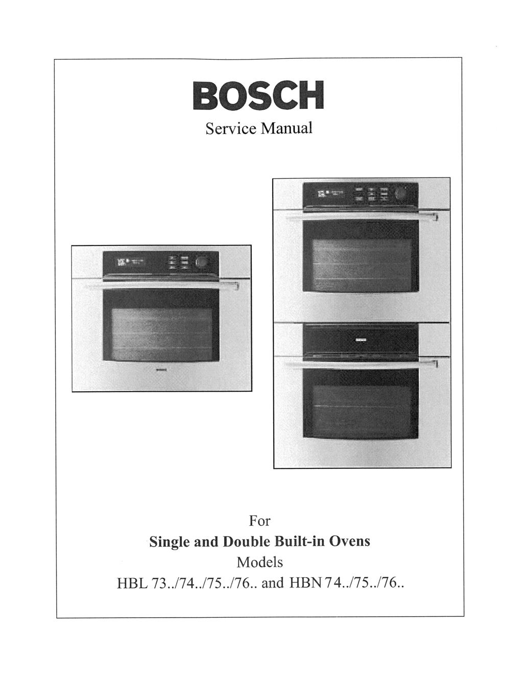
Heating elements BSH/series 700 -convection system- FULGOR. SpA ELETTRODOMESTICI
|
|
|
- June Parsons
- 6 years ago
- Views:
Transcription
1
2
3
4 Heating elements BSH/series 700 -convection system- FULGOR ELETTRODOMESTICI SpA
5 The following illustrations give an overview of what happens in the oven with each mode setting. The arrows represent the location of the heat source during specific modes. The lower element is concealed under the oven floor. Oven Modes CONVECTION ROAST Convection Roast uses the top element, bottom element and convection fan. BAKE and WARMING Baking is cooking with heated air. Both the upper and lower element cycle to maintain the oven temperature. In the Warming mode, the oven will use the lower element to maintain a low temperature to keep food at serving temperature. BROIL Broiling uses intense heat radiated from the upper element. CONVECTION BAKE and DEHYDRATE Convection Bake cooks with heat from a third element behind the back wall of the oven. The heat is circulated throughout the oven by the convection fan. Dehydrating is similar to convection cooking and holds an optimum low temperature while circulating the heated air to remove moisture slowly for food preservation. CONVECTION BROIL Convection Broil combines the intense heat from the upper element with the heat circulated by the convection fan.
6 Double Oven Control Panel Upper Cancel Light Time 3 4 Cooking Mode Temperature Lower Cancel Upper / Lower Start
7 Single Oven Control Panel 1 Light Time Cancel Cooking Mode Temperature Start
8
9 Setting the Clock The time of day is displayed in hours and minutes. Always set the clock immediately after installation or after a power failure. Once power returns to the oven, the clock displays the time of day when the power was turned off or lost. The clock time will appear during all oven operations except when the timer or a timed cooking operation is running. The oven is preset to a 12-hour clock and indicates AM and PM. TO SET THE CLOCK: 1. Touch TIME. The display will begin flashing TIMER. 7:21 PM TIMER 2. Turn rotary knob once to the right or left and CLOCK will flash in display. 7:21 PM CLOCK 3. Touch TIME again. ENTER TIME will appear in the display and clock time will flash. ENTER TIME 4. Turn the knob to the right or left to quickly move the clock time forward or backward by 10-minute increments. Continue to rotate knob until correct AM or PM is selected. 5. After the initial move of the knob to either the right or left, turn the knob in the opposite direction to change the time by 1-minute increments. 6. Touch START. The clock is now set. If operation is not completed, the oven will beep periodically as a reminder to set clock time. Touch START. To cancel the CLOCK selection, touch CANCEL at any time when setting the clock. 7:21 PM
10 TO SET THE TIMER: 1. Touch TIME once. Display timer will begin flashing and TIMER will appear in display. Using Oven Timer TO CHANGE THE TIMER: 1. Touch TIME 2 times. Display timer will begin flashing and CHANGE TIMER will appear in display. 9:31 AM TIMER 2. Touch TIME again and TIMER will appear in display (below clock time). Oven timer will begin flashing. 0:00 HR:MIN TIMER TIMER 3. Turn knob to the right to increase set time. 4. Turn knob to the left to decrease set time. 5. If the knob is turned too far to the left past zero, then the time will roll over to 59 hr 59 min. 0:34 CHANGE TIMER HR:MIN TIMER 2. Turn knob to change set time. 0:30 CHANGE TIMER HR:MIN TIMER 3. Touch START. 4. If START is not touched, oven will begin beeping, timer display will begin flashing and PRESS START will appear in display. TO CLEAR THE TIMER: 1. Touch TIME once. Display will begin flashing CHANGE TIMER. 0:35 HR:MIN TIMER TIMER 0:24 HR:MIN TIMER CHANGE TIMER 6. Touch START. If START is not touched, oven will beep as a reminder and PRESS STARTwill appear in display and time will flash. 0:35 PRESS START HR:MIN TIMER 7. END will appear in display when time ends. Reminder beeps will sound for up to fifteen minutes or until any pad is touched. A single light pad activates the lights in either oven. If LIGHT pad is touched when both ovens are off, lights in both the upper and lower oven will turn on. Touch LIGHT pad again, and both oven lights will turn off. Oven lights turn on and off automatically when the door is opened and closed. When an oven is in use, oven lights turn on automatically when a mode is selected and START Using Oven Lights 2. Turn knob once to right and CLEAR TIMER will flash in display. 0:24 CLEAR TIMER HR:MIN TIMER 3. Touch TIME. 4. Timer is now cleared and clock time appears in display. 5. If TIME pad is not touched, oven will beep and CLEAR TIMER will continue to flash in display. is touched. Oven lights will turn off automatically when the oven mode is cancelled. The lights do not operate in the Self-Clean mode. To manually control the interior oven lights in either the upper or lower oven if one or both ovens are in use: 1. Touch UPPER/LOWER. The display will indicate which oven is selected. 2. Touch UPPER/LOWER to highlight the other oven. Touch LIGHT to turn lights on or off.
11 Selecting the Oven Mode The following oven modes will appear in the display when COOKING MODE is touched and the knob is turned: BAKE BROIL CONVECTION BAKE CONVECTION BROIL CONVECTION ROAST CLEAN WARMING FAST PREHEAT BAKE FAST PREHEAT CONVECT BAKE DEHYDRATE SABBATH (optional) When the oven is operating, the selected cooking mode will be displayed. The oven temperature will appear in the dispaly. TO SET A COOKING MODE: 1. For double ovens, touch UPPER/LOWER to select the upper oven or lower oven. The selected oven will be highlighted in the display. 2. Touch COOKING MODE. 3. The last mode used will flash in the display. The default temperature for that mode will also be displayed. 5. To select a different mode, turn the knob to the right or left. 6. The selected mode will appear in the display, along with the default temperature for that mode. 7. To select a different temperature, touch TEMPERATURE and turn knob to the right or left. Temperature can be changed by 5 F. 8. If START is not touched, oven will beep as a reminder and PRESS STARTwill appear in display and temperature will flash. 350º F 7:09 PM BAKE PRESS START 9. Touch START. 10. Oven will begin to heat and oven light will turn on. The temperature display shows the actual temperature, beginning with 100ºF. The actual temperature counts up in 5ºF increments until set temperature is reached. 11. In modes that require preheat, PREHEAT is displayed. When oven has preheated, oven will beep and PREHEAT disappears from display. 12. To change temperature during cooking, simply touch TEMPERATURE. Turn the knob to select new temperature and press START. 13. Once cooking has been completed, touch UPPER CANCEL or LOWER CANCEL to turn off oven. 350º F BAKE 7:09 PM 4. If no further setting is made, display will disappear. Example: 350º f 6:35 PM BAKE PREHEAT Upper Cancel Lower Cancel Light Time Upper Lower Cooking Mode Temperature Start +
12 In double oven models, both ovens can be set independently to operate a timed mode. Be sure that the time-of-day clock is displaying the correct time. The timed mode turns off the oven at the end of the cook time. TO SET TIMED MODE: Time Oven Mode Operation 1. Select oven by touching UPPER/LOWER. 2. Touch COOKING MODE. The last cooking mode used will flash in display. To select a different cooking mode, turn the knob. If necessary, change the default temperature at this time by touching TEMPERATURE. Turn knob to select different temperature. 3. Touch TIME two times. COOKTIME will appear in the display and time display will begin flashing. 400ºF CONVECTION ROAST 0:00 COOK TIME 4. Turn knob to enter cooking time. Keep in mind that the time required for the oven to reach temperature must be included in the set cooking time. 5. Touch START. 6. At the end of the programmed cooking time, the oven will automatically turn off. 3. Use knob to enter the time of day the oven will stop cooking or turn off. 400ºF CONVECTION ROAST 8:30 AM STOPTIME 4. Touch START. 5. The clocktime will be displayed and DELAY appears in the display. CONVECTION ROAST 7:10 AM DELAY 6. The clock automatically calculates the time of day at which the mode starts and stops. The displayed cooking time counts down by the minute. The oven turns on and heats to the temperature selected for the number of hours and minutes needed. 400ºF CONVECTION ROAST 7. At the end of the programmed cooking time, the oven will automatically turn off. Display will show OFF and the oven will beep. Reminder beeps will sound for up to fifteen minutes until any pad is touched. 8. To check the cooking time and stop time after a delay has been set, touch COOKING MODE. TO DELAY THE START OF A TIMED MODE: 1. Follow steps 1 through 4 above. 2. Touch TIME again and STOPTIME will appear in display and clock time display will begin flashing. 400º F CONVECTION ROAST 7:09 PM STOPTIME 0:35 CONVECTION ROAST The cooking mode will flash in the display and the set cooking time will be displayed. Touch TIME three times and STOP TIME will appear in display and the time-of-day the oven will stop cooking can be seen. Touch START to return to DELAY display.
13 Special Features The Special Features function can be used to select the following 10 special oven features: 1. LOCK KEYS (Child Lockout) 2. SABBATH MODE (for religious faiths with no work requirements on the Sabbath) 3. OVEN OFFSET 1 (upper oven used to calibrate the oven temperature) 4. OVEN OFFSET 2 (lower oven used to calibrate the oven temperature) 5. LANGUAGE (select English, Spanish, or French) 6. SELECT UNITS (switch temperature scale to Fahrenheit or Centigrade) 7. CLOCK FORMAT (12 hr or 24 hr) 8. BEEP VOLUME (decrease or increase loudness of oven beeps) 9. VIEW CLOCK (yes or no) 10. DEFAULT DATA (change all feature settings back to original factory settings) To select special features, follow the steps below: a. Touch and hold COOKING MODE for 3 seconds. b. Clock time disappears and display screen clears. c. The four display screen messages shown below will automatically appear, one after the other. OVEN SETTINGS HELP SCREENS PLEASE READ TO EXIT AND LOSE CHANGES PRESS CANCEL TO EXIT AND KEEP CHANGES PRESS START TO BEGIN TURN KNOB THANK YOU Tips on Using Special Features: There will be a slight delay before each message (or feature) can be seen in the display. Turn knob slowly, one click then wait approximately one second for display to show next feature. Turn knob one more click and pause for next feature. When selecting a feature, the display will read PRESS MODE TO SELECT. To move through the feature menu, slowly turn the knob clockwise one click after each feature appears. FEATURE #1 LOCK KEYS (YES or no) 1. Select Special Features. 2. Turn knob clockwise slowly until LOCK KEYS is displayed. 3. Touch COOKING MODE. 4. Turn knob once and YES will appear in screen. 5. Touch COOKING MODE to hold new selection. 6. Touch START to accept new setting. 7. If a pad is now touched, display will read KEYS LOCKED. 8. To unlock keypads, touch COOKING MODE and hold for 5 seconds. Display will now read KBD UNLOCKED (keypads unlocked). This feature can be used as the child lock-out feature. no LOCK KEYS
14 TO SET THE SELF-CLEAN MODE: Setting the Self-Clean Mode 1. Touch UPPER/LOWER to select oven to be cleaned. 2. Touch COOKING MODE. 3. Rotate knob until CLEAN mode appears. The number of cleaning hours is displayed automatically. CLEAN 3:00 TIME 4. To change the setting from 3 hours, select either 2 hours for light soil or 4 hours for heavy soil immediately before starting. To change hours, touch TIME twice. Number of hours to clean will flash in display. 4:00 CLEAN 3:00 TIME Rotate knob to select number of hours. CLEAN 4:00 TIME 5. Touch START pad and REMOVE RACKS appears in the display as a reminder to remove oven racks. REMOVE RACKS 6. Touch START again. Do not attempt to open the door while the door is locking. Lock symbol will appear after a short delay. When the lock symbol is displayed, the door cannot be opened. Confirm that the door locks and will not open before starting Self-Clean mode. CLEAN 3:00 TIME If door does not lock, press UPPER CANCEL or LOWER CANCEL and do not self-clean; phone 800/ for service (see Page 39 for obtaining service). If the door is in the open position when this mode is selected, CLOSE DOOR will appear in display. 7. At the end of the programmed cleaning time, the oven will automatically turn off. 8. To cancel or stop the mode after the lock symbol is displayed, touch UPPER CANCEL or LOWER CANCEL. TO DELAY THE START OF THE MODE: 1. Follow steps 1 through 4 above. 2. Touch TIME pad again and clock time will begin flashing and STOPTIME will appear in display. CLEAN 5:51 STOPTIME 3. Use knob to enter a Stoptime. 4. Touch START once and display will remind you to remove oven racks. 5. Touch START to set the Delay mode. CLEAN 5:51 DELAY 6. Oven door will lock and display shows DELAY. 7. At the end of the programmed cleaning time, the oven will automatically turn off. 8. To cancel or stop the mode after the lock ( ) symbol is displayed, touch UPPER CANCEL or LOWER CANCEL. TO CHECK CLEAN TIME FOR DELAYED SELF-CLEAN: 1. Touch TIME one time. TIMER will flash in display. 2. Turn knob slowly to the right and TIME will flash in display. 3. Touch TIME again and the actual clean time will appear in display. 4. After a short pause, the oven will automatically revert to the DELAY message in the display. TO CHECK STOP TIME FOR DELAYED SELF-CLEAN: 1. Touch TIME one time. TIMER will flash in display. 2. Turn knob slowly to the left and STOPTIME will flash in display. 3. Touch TIME again and the actual stop time will appear in display. 4. After a short pause, the oven will automatically revert to the DELAY message in the display.
15 BSH wall ovens Series 700 Maintaining And Cleaning To clean the cavity and the inner door never use any metal tool. After the Pyrolytic Cleaning process use only a damped cloth or sponge with dish soap for final cleaning of the surfaces. Grids and cookie sheets must always be removed before using the Selfcleaning mode. Otherwise chromed metal grids wiii be discolored and not be shiny anymore. The cleaning time can be chosen between 2-4 hours depending on the Ievel of soil the cavity has collected. If the door gasket has become dirty it should only be cleaned very carefully with a damped and soaped rag. Consider that the Selfcleaning process wili not clean the gasket. Particles or dust between the glass Iayers of the door window can only be cleaned after disassembling of the complete door. This operation should only be done by an authorized service technican. The front surface of the unit should be cleaned only with soapy water and a rag or sponge. 7. Stainless steel panels must be carefully cleaned with a soft damped rag or sponge and dish soap. Never use any rubbing materials Iike metal wool, abrasive sponges or scouring pads of any type. This wiii create shiny marks or scratches which never can be repaired and wiii remain. Clean the stainless steel panels always only in one direction and follow the satinated structure on the panels. FULGOR - Training
16 MEAT PROBE COOKING ************* - Temperature probe range is 130 F to 210 F (55 C to 100 C), while the default setting is 170 F (77 C). - Maximum cavity temperature when using meat probe is 475 F (245 C). ************* 1. Insert the probe inside the thickest portion of meat. 2. Plug the meat probe in its receptacle and check that the probe icon is displayed. 3. Press [Cooking Mode] key to select the desired cooking mode. Only some of the cooking modes are available for probe cooking: a. BAKE b. CONVECTION BAKE c. CONVECTION ROAST d. FAST PREHEAT BAKE e. FAST PREHEAT CONVECTION BAKE 4. Press once [Temperature] key to change the probe temperature setpoint, twice to change the cavity temperature set-point. The icon is flashing while the probe temperature is in edit mode. Set the desired values, by rotating the knob CW or CCW, then press [Start] to accept the cooking mode. 5. As soon as the meat probe reaches its set point temperature, the icons turn off. The control displays OFF to indicate probe cooking complete and cancels the cooking activity. 6. The icon is still displayed until the probe is removed. *************
17 OVEN REGULATION PARAMETERS FOR COOK MODES Serial # Cooking Function Conv Fan Speed Default Temperature C / F Elements used during Preheat Operation Fullpower On-Time (1) (in seconds) period in seconds Lower Upper Ring Additional 1 Bake (3) / Convection Preheat cycle Full Bake Normal cook cycle Reduced 160 / Dehydrate Low Power Convect Bake Full 60 / Convection Preheat cycle Full Roast Normal cook cycle Reduced 160 / LEVEL 1 = 11sec. LEVEL 2 = 21sec. 5 Broil - Level LEVEL 3 = 31 sec. LEVEL 4 = 42sec. LEVEL 5 = 52sec Convection Preheat cycle Full Broil Normal cook cycle Reduced 245 / Self-Clean Full (2) 8 Warming Low Power Bake (3) - 75 / Fast Preheat Preheat cycle Full 175 / Bake Normal cook cycle / Fast Preheat Preheat cycle Full 160 / Convection Bake Normal cook cycle Reduced 160 / NOTE 1: The control will follow the on time ratio for the particular cookmode when cooking. NOTE 2: The additional element in a Self-Clean will only be used when the Voltage service to the oven is 208VAC. NOTE 3: For Bake and Warming modes, period and element times are divided in half for control temperatures lower than 250 F. NOTE 4: In any cooking mode, the associated element icon and fan will always be ON in the display when the cooking mode is active. In Fast Preheat Bake, the icon will switch to bake state at steady conditions.
18 Comparison between Bake and Fast Preheat Bake 00:00:00 00:13:20 00:01:40 00:03:20 00:05:00 00:06:40 00:08:20 00:10:00 00:11:40 00:15:00 00:16:40 00:18:20 00:20:00 00:21:40 00:23:20 00:25:00 00:26:40 00:28:20 00:30:00 00:31:40 00:33:20 00:35:00 00:36:40 00:38:20 00:40:00 00:41:40 00:43:20 00:45:00 00:46:40 BakeCentre BakeSensor FPBakeCentre FPBakeSensor Setpoint time (hr:min:sec) Temperature ( C)
19 SABBATH MODE ************* - To select Sabbath mode, press [Cooking Mode] key for some seconds while in stand-by to enter the user options menu and select the item. - Sabbath is actually a bake mode, with additional no work requirements due to religious faith. - To start a Sabbath in one cavity, select it by pressing [cooking mode] key and rotating the knob, then pressing [start] key, as usual. - To start a Sabbath in both cavities, in a double oven, first start a Bake in the lower one, then start Sabbath in the upper one. Both will run Sabbath mode. - When Sabbath is running, no work requirements are: 1. Working fan is disabled. 2. Light switching is not possible even when opening the door. 3. Latch motor is disabled. 4. No beep tones are allowed. 5. The display is prevented from changing messages, flashing, etc. 6. Keys are disabled with the exception of [Cancel] for single oven and [Upper Cancel, Lower Cancel] for the double. 7. Timed and delayed cooking are not allowed. 8. Minute minder is disabled too. 9. Probe cooking is not available. Press the correspondent [Cancel] key to stop Sabbath. *************
20 SYSTEM PARTS 1. DISPLAY BOARD. It s mounted on the front panel, it s the oven brain. It handles the user interface (display, keyboard and knob), receives inputs and send information to drive all outputs through the Power Board. 2. POWER BOARD. It s mounted on the cooling channel, it provides the Display Board with all its power lines. It manages the latch, the heaters, the auxiliary loads following the Display Board indications. It measures the temperature read by the sensor. 3. HEATING ELEMENTS (nominal power at 240V). a. UPPER ELEMENT 3500W b. LOWER ELEMENT 3000W c. RING ELEMENT 2500W d. ADDITIONAL ELEMENT 1000W 4. AUXILIARY RELAY BOARD. It s mounted on the front panel. It provides the working fan dual speed (only double oven) and the Double Line Break feature (only for Canadian requirements).
21 5. SAFETY THERMOSTATS. The oven is provided with two safety thermostats. They simply cut off L2 when temperature inside gets too high. The high temperature one (165 C) is always in series with the heaters, the low temperature (110 C) is by-passed during self-clean. They are mounted together, behind the cooling fan. 6. KLIXON RELAY BOARD. It s mounted on the cooling channel, to by-pass the low temperature safety thermostat during self-clean. 7. TOUCH KEYBOARDS. They can be 6 pads (single oven) or 8 pads (double oven). They are glued on the front panel glass. 8. ROTARY SWITCH. It s activated through the knob on the front panel. The control detects rotation verse and number of ticks. 9. TEMPERATURE SENSORS. They are mounted inside the cavity, fixed from the outside, on the rear wall. The only mean to measure oven temperature. 10. LATCH MECHANISM. To lock the door when self-clean is running, until the cavity cools down. 11. AUXILIARY LOADS. Working and cooling fans, oven lights, for both cavities.
22 12. MEAT PROBE. The oven is provided with a meat probe, which needs only to be plugged in its receptacle on the cavity left side wall.
23 IMPORTANT WARNINGS 1. LATCH AUTO-TEST. At power-up, the control runs a latch mechanism self-test. The display shows the message UNLOCKING DOOR until both cavities have completed their lock/unlock cycle. This allows the user to restore the latch position, in case of any problem: turn off the main power supply and wait for a few minutes before re-powering. Each latch takes about 30sec. to run the test. If the control can t complete this test, power down the oven, search for a hardware fault and remove it. 2. BY-PASSING LATCH TEST. If there is any reason to by-pass the latch test, at power-up, simply keep the [Start] key pressed until the clock is displayed. 3. OVEN MODEL SELECTION OR MANUAL TEST. If you intend to enter this special sections, never press [Cooking Mode] key before doing it because the two features will be disabled. In any case, both features must be accessed within 5 minutes from the power-up.
24 OVEN MODEL SELECTION This operation is normally executed at the manufacturer facilities. If the display board has to be replaced, the oven model must be reconfigured. At first power-up, the Double Oven is always configured as a 30 both multifunction cavities. MANUAL TEST ACCESS PROCEDURE: 1. Press CANCEL key. 2. Turn the knob 4 detents CW. 3. Turn the knob 6 detents CCW. 4. Press START key. 5. The writing MANUAL TEST is displayed. To reconfigure the oven model as a different double: 1. Press [Cooking Mode] key. 2. Turn the knob to select the correct oven model. N MOD DISPLAY OVEN MODEL 1 C 30 CONVECT 2 30 DOUBLE OVEN MULTIFUNCTION/MULTIFUNCTION 3 D 30 THERMAL 2 30 DOUBLE OVEN MULTIFUNCTION/THERMAL 5 G 27 CONVECT 2 27 DOUBLE OVEN MULTIFUNCTION/MULTIFUNCTION 7 H 27 THERMAL 2 27 DOUBLE OVEN MULTIFUNCTION/THERMAL 3. Press [Start] key to accept the new selection, the control sounds a tone. 4. Press [Cooking Mode] key again to quit the oven model menu and going back to manual test procedure.
25 OVEN MODEL SELECTION SINGLE OVEN This operation is normally executed at the manufacturer facilities. If the display board has to be replaced, the oven model must be reconfigured. There is only one single part number for the display board then, after having replaced it, also a single oven is configured as a double oven 30 Multifunction/Multifunction. IMPORTANT: ALWAYS KEEP PRESSED START KEY AT FIRST POWER-UP ON A SINGLE OVEN, UNTIL THE CLOCK IS DISPLAYED. Otherwise, the control will try to run the latch auto-test but, missing one cavity, it will never be able to complete it. At first power-up, the control realizes that one cavity is missing: the display shows a calibration error message. Ignore it and proceed with the MANUAL TEST ACCESS PROCEDURE 1. Press CANCEL key. 2. Turn the knob 4 detents CW. 3. Turn the knob 6 detents CCW. 4. Press START key. 5. The writing MANUAL TEST is displayed.
26 To reconfigure the oven model as a single: 1. Press [Cooking Mode] key. 2. Turn the knob to select the correct oven model. N MOD DISPLAY OVEN MODEL 0 A 30 CONVECT 1 30 SINGLE MULTIFUNCTION 2 B 30 THERMAL 1 30 SINGLE THERMAL 4 E 27 CONVECT 1 27 SINGLE MULTIFUNCTION 6 F 27 THERMAL 1 27 SINGLE THERMAL 3. To confirm the selection: a. If the Display Board is still configured as a double, KEEP THE [START] KEY PRESSED UNTIL THE CLOCK APPEARS ON THE DISPLAY. The control resets itself. b. If the Display Board is already configured as a single, press the [Start] key to accept the new selection, the control sounds a tone. Press then [Cooking Mode] key again to quit the oven model menu and going back to manual test procedure.
27 POWER SUPPLY SELECTION The oven provides a 208V power supply option, for areas where the standard 240V is not available. First connect the oven to power then, to access this option, follow the procedure below: 240V/208V POWER SELECTION: 1. Open the oven door (upper oven for double). 2. Turn the knob 6 detents CW. 3. Turn the knob 9 detents CCW. 4. Press [Start] key SELECTED is displayed (or 208 SELECTED). 6. Press [Cooking Mode] key to change selection. 7. Touch [Start] key to confirm the new selection.
28 MANUAL TEST The scope of the test is to check all the control outputs independently. Turn the knob CW to proceed with the following steps. Single oven has only step 1 to 8. N CAVITY DISPLAY ACTIVATED OUTPUT 1 UPPER UPPER ELEMENT 2 UPPER LOWER ELEMENT 3 UPPER RING ELEMENT 4 UPPER ADDITIONAL ELEMENT Upper element (3500W at 240V). Lower element (3000W at 240V). Ring element (2500W at 240V). Additional element (1000W at 240V). 5 UPPER LIGHT Oven lights are activated. 6 UPPER CONV. FAN LO 7 UPPER CONV. FAN HI 8 UPPER COOLING FAN Working fan at low speed. Working fan at high speed. Cooling fan at ordinary speed.
29 In a double oven, steps 1 to 8 are for upper cavity, steps 9 to 16 are for the lower one. 9 LOWE R 10 LOWE R 11 LOWE R 12 LOWE R 13 LOWE R 14 LOWE R 15 LOWE R 16 LOWE R UPPER ELEMENT LOWER ELEMENT RING ELEMENT ADDITIONAL ELEMENT LIGHT CONV. FAN LO CONV. FAN HI COOLING FAN Upper element (3500W at 240V). Lower element (3000W at 240V). Ring element (2500W at 240V). Additional element (1000W at 240V). Oven lights are activated. Working fan at low speed. Working fan at high speed. Cooling fan at ordinary speed.
30 OPERATIONS TO CHECK REMAINING FUNCTIONALITIES 1. Latch mechanism and cooling fan high speed. Press [Cooking Mode] key then turn the knob CW until the CLEAN mode is found. Press [Start] key once and again when the writing REMOVE RACKS appears. The control runs the latch until the door is locked. Just a while before the lock symbol is displayed, the cooling fan switches to high speed. Check that the door is actually fully locked. To unlock the door, press [Cancel] key and wait for the lock symbol on the display disappear. Now the door has to be fully unlocked. 2. Door switches and cavity lights. Open the door, if the cavity lights turn on it means that the control has detected a change. Close the door, the lights must turn off. If the lights don t turn on, try to press the [Light] key and be sure to hear a key pressed tone. If the lights still remain off, they are probably broken. If no tone is heard, then the [Light] key is not working. 3. Keyboard and thermal cavities. Select the lower cavity by pressing [Upper/Lower] key, until the box is displayed in the lower oven position (only for double oven). Press [Cooking Mode] key, BAKE will flash. Turn the knob CW until BAKE mode is found again. If the cavity is set as thermal, only BAKE, BROIL CLEAN and WARMING must be available. Press [Temperature] key and see that the displayed temperature is flashing. Press [Start] to run the cooking mode then [Lower Cancel] (simply [Cancel] for a single oven) to stop it.
31 4. Meat probe. Plug the meat probe in its receptacle, on the left side in the cavity. In a double oven only the upper cavity can be used for probe cooking. The probe icon on the display must be shown whenever the probe is inserted. If it blanks or flashes a problem in the connection may exist. Only BAKE, CONVECTION BAKE, CONVECTION ROAST, FAST PREHEAT BAKE and FAST PREHEAT CONVECTION BAKE must be available for cooking. When probe cooking is running or before starting, press [Temperature] key: a. Once, to edit the probe temperature edit state (probe icon and temperature flash). b. Twice, to edit the cavity temperature (temperature flashes). When probe cooking is running, the actual probe temperature is displayed. 5. [Time] key + knob. Press [Time] key, TIMER is displayed. Press it once again, in the time area 0:00 starts flashing. Turn the knob 5 detents CW and check that time increments by one each detent until 0:05 is displayed, then turn 5 detents CCW and check that time decrements by 1 each detent until the timer is back to 0:00. Press [Time] key again to display the clock again. NOTE: This last five actions allows to check all the devices which haven t been tested yet during the Manual Test, including the keyboard and the rotary switch.
32 Tuesday, June 18, 2002 ELETTRODOMESTICI VIA CHECCHI 98 I GALLARATE ITALY BOSCH 700 SERIES: SERVICE INSTRUCTIONS FOR OVEN TESTING AND BASIC TROUBLESHOOTING SYSTEM PARTS 1. DISPLAY BOARD. Mounted on the front panel, it s the oven brain. It manages the user interface (VFD display, selection knob and keyboard), receives inputs (directly from the field or by means of the Power Board) and sends information to the Power Board to drive all outputs (heaters and auxiliary loads). 2. V.F.D. (Vacuum Fluorescent Display). It s mounted on the Display Board and is used to display information for users and technical operators. 3. POWER BOARD. It s mounted on the cooling channel; it provides the Display Board with all its power lines. It manages the latch mechanism, the heaters, the oven lights and the fans, according to the Display Board indications. It measures the temperatures read by the RTD sensors in the cavities. 4. AUXILIARY RELAY BOARD. It s mounted on the front panel. It provides the Double Line Break feature for Canadian requirements and, for the double oven only, the working fan high speed ND THERMOSTAT RELAY BOARD. It s mounted on the cooling channel, to by-pass the low temperature safety thermostat during self-clean. See electric schematics to see how it works. 6. TOUCH KEYBOARDS. There are two different keyboard models, providing the single oven with 6 pads and the double with 8 pads. They are glued on the front panel glass. 7. HEATING ELEMENTS (nominal power at 240V). a. UPPER ELEMENT 3500W b. LOWER ELEMENT 3000W c. RING ELEMENT 2500W d. ADDITIONAL ELEMENT ~1000W (Actually its nominal value is 775W at 208V) Page 1 of 28
33 Tuesday, June 18, 2002 ELETTRODOMESTICI VIA CHECCHI 98 I GALLARATE ITALY BOSCH 700 SERIES: SERVICE INSTRUCTIONS FOR OVEN TESTING AND BASIC TROUBLESHOOTING 8. SAFETY THERMOSTATS. The oven is provided with two safety thermostats, mounted together, behind the cooling fan. The high temperature one (165 C) is always connected in series with the heaters, the low temperature (110 C) is by-passed during self-clean. They open L2 circuit when temperature gets too high. 9. ROTARY SWITCH. By means of the knob placed on the front panel, the user activates this electronic device. The control counts the detents and is also able to distinguish if the rotation verse is clockwise or counterclockwise. 10. RTD TEMPERATURE SENSORS. They are mounted inside the cavity (one per cavity), fixed from the outside, on the rear wall. They are the only means to measure oven temperature. 11. LATCH MECHANISM. A motor is activated to lock the door as soon as self-clean starts. When clean stops, the control wait for the cavity cooling down below the temperature threshold. The same motor moves to unlock the door. 12. COOLING FAN. It works at two different speeds, in self-clean and ordinary cooking modes. A resistor in series reduces the voltage on the fan motor and consequently it lowers the fan speed. When the door is locked in self-clean, the resistor is bypassed by a latch contact, in order to run the fan at full speed. 13. CONVECTION FAN. It works at reduced speed in preheat phase and at full speed at steady conditions. Clean always work at full speed. A resistor in series with the fan coil reduces the speed, a relay driven by the control by-passes this resistor when requested. 14. OVEN LIGHTS. Halogen 12V lamps, powered by a 4VA transformer, fused on its secondary winding. 15. MEAT PROBE. The oven is provided with a meat probe, which needs only to be plugged in its own receptacle on the cavity left side. In the double oven, only the upper cavity is provided with the meat probe. Page 2 of 28
34 Tuesday, June 18, 2002 ELETTRODOMESTICI VIA CHECCHI 98 I GALLARATE ITALY BOSCH 700 SERIES: SERVICE INSTRUCTIONS FOR OVEN TESTING AND BASIC TROUBLESHOOTING USEFUL INFORMATION ABOUT THE ELECTRONIC CONTROL: 1. SHORT POWER OFF. In case of power loss for a short time, the control saves the currently active settings in its memory. It fetches all these values as soon as power recovers. The oven comes back to the same working condition it was before the power drop. Such a time is variable, more or less a few dozens of seconds, depending on the tolerances of some components on the electronic boards. 2. LONG POWER OFF. When the time expires, the control forgets the former working condition and, as soon as power recovers, it performs a complete reset. It shows the SW code numbers and the writing UNLOCKING DOOR, while the power-up latch auto-test is running. The control is now in a stand-by state; the clock is blinking, waiting for a new user operation. This means that, in case of problems with the latch positioning, the best thing to do is turn off the oven, wait at least for one minute before re-powering the unit, to cause a system reset and run a complete latch lock/unlock cycle. 3. AVOIDING LATCH AUTO-TEST AT POWER-UP. For whatever reason, if the technician prefers to skip the latch auto-test at power-up, he just needs to keep the [START] key pressed while supplying the oven with power, until the clock is displayed again. 4. PERSISTING FAULTS OR INHIBITED FUNCTIONS. When the control detects a fault, fist the cause needs to be removed. Sometimes, for safety reason after a fault, self-clean or even all cooking modes are disabled. Once the fault cause has been removed, if the disabling condition persists, keep the [START] key pressed for one minute, until the F121 fault occurs then press [CANCEL]. 5. WARNING: At every power-down, the control saves the time in its memory but sometimes it doesn t succeed in writing the right checksum value. At the next power-up, the F155 fault code is displayed. Press [Cancel] key to reset the fault, the oven will work correctly. If F155 is displayed when starting a cooking mode, it means that the Display Board must be replaced, having corrupted parameters in memory. Page 3 of 28
35 Tuesday, June 18, 2002 ELETTRODOMESTICI VIA CHECCHI 98 I GALLARATE ITALY BOSCH 700 SERIES: SERVICE INSTRUCTIONS FOR OVEN TESTING AND BASIC TROUBLESHOOTING OVEN MODEL SELECTION This operation is normally executed at the manufacturer facilities. When a Display Board needs to be replaced in the field, Service Technicians must take care of it. One single part number exists for the Display Board: its default configuration is: 30 Double Oven - Upper Multifunction Cavity / Lower Multifunction Cavity After installing a new Display Board, at first power-up, the action must be: SELECT THE CORRECT OVEN MODEL Two different kinds of transition exist: DBL=>DBL DBL=>SGL The DBL=>SGL transition occurs only once. The transition SGL=>DBL is never allowed. Once a Display Board has been already reconfigured as a SGL, the transition SGL=>SGL is also possible. WARNING ALWAYS KEEP PRESSED [START] KEY WHEN YOU FIRST POWER-UP THE OVEN, UNTIL THE CLOCK IS DISPLAYED. Single Oven: this action prevents the control from running the power-up latch auto-test and it s absolutely important when a Display Board is installed in a Single Oven for the first time. Being still configured as a DBL, the control can t perform successfully the latch test. If this event occurs unintentionally, remove power and repeat the procedure after a few minutes. Double Oven: the latch test can be performed correctly, even before configuring the oven model. Keeping pressed [START] key just allow the operator to save time. Wait for the clock to appear, before releasing the [START] key. Page 4 of 28
36 Tuesday, June 18, 2002 ELETTRODOMESTICI VIA CHECCHI 98 I GALLARATE ITALY BOSCH 700 SERIES: SERVICE INSTRUCTIONS FOR OVEN TESTING AND BASIC TROUBLESHOOTING WARNINGS DON T PRESS [COOKING MODE] KEY BEFORE ENTERING MANUAL TEST. THE PROCEDURE WILL BE DISABLED. MANUAL TEST CAN BE ACCESSED WITHIN 5 MINUTES AFTER POWER-UP. MANUAL TEST QUITS AFTER A 4 MINUTES TIME-OUT IF IDLE. The control is still configured as a double, at this point. Only on a single oven, missing the lower cavity, the following error messages will be displayed: POWER UP SEE CAL VAL ERROR (CONDITION) SLV_EE CHIP/ CKT BAD OR RTDS NOT CAL DO NOT USE OVEN CALL SERVICE Ignore it and enter the MANUAL TEST through the following procedure: MANUAL TEST ACCESS PROCEDURE (both for DBL and SGL): 1. Press [CANCEL] key. 2. Turn the knob 4 detents CW. 3. Turn the knob 6 detents CCW. 4. Press [START] key. The writing MANUAL TEST is displayed. Now press [Cooking Mode] key, the control will recognize automatically if the oven is a single or a double. Turn the knob to select the correct oven model. Page 5 of 28
37 Tuesday, June 18, 2002 ELETTRODOMESTICI VIA CHECCHI 98 I GALLARATE ITALY BOSCH 700 SERIES: SERVICE INSTRUCTIONS FOR OVEN TESTING AND BASIC TROUBLESHOOTING The tables below show the two different sets of options when entering the oven model selection menu for the double or single oven: N MOD DISPLAY DOUBLE OVEN MODELS 1 C 30 CONVECT 2 30 DOUBLE OVEN MULTIFUNCTION/MULTIFUNCTION 3 D 30 THERMAL 2 30 DOUBLE OVEN MULTIFUNCTION/THERMAL 5 G 27 CONVECT 2 27 DOUBLE OVEN MULTIFUNCTION/MULTIFUNCTION 7 H 27 THERMAL 2 27 DOUBLE OVEN MULTIFUNCTION/THERMAL N MOD DISPLAY SINGLE OVEN MODELS 0 A 30 CONVECT 1 30 SINGLE MULTIFUNCTION 2 B 30 THERMAL 1 30 SINGLE THERMAL 4 E 27 CONVECT 1 27 SINGLE MULTIFUNCTION 6 F 27 THERMAL 1 27 SINGLE THERMAL KEEP THE [START] KEY PRESSED DBL=>SGL transition: the Display Board resets itself. Wait for the clock on the display. DBL=>DBL or SGL=>SGL transition: the control accepts the new selection, sounds a tone and updates the letter in the _0047 code displayed. The Display Board doesn t reset. Press [Cooking Mode] key again to quit the oven model selection menu and go back to Manual Test. Page 6 of 28
38 Tuesday, June 18, 2002 ELETTRODOMESTICI VIA CHECCHI 98 I GALLARATE ITALY BOSCH 700 SERIES: SERVICE INSTRUCTIONS FOR OVEN TESTING AND BASIC TROUBLESHOOTING After a system reset, the following writings are displayed: V0515 C0047 F000 C2K2EAC They indicate: 1. The SW flash program code V The EEPROM file number C0047, whereas the C red letter indicates the oven model (A, B, E, F for the single oven, C, D, G, H for the double oven). 3. The last saved fault number, whereas F000 means no faults saved. 4. C2K2EAC means Copyright 2002 Emerson Appliance Controls. POWER SUPPLY SELECTION The oven provides a 208V power supply option, for areas where the standard 240V is not available. First connect the oven to power then, to access this option, follow the procedure below: 240V/208V POWER SELECTION: 1. Open the oven door (upper oven for double). 2. Turn the knob 6 detents CW. 3. Turn the knob 9 detents CCW. 4. Press [Start] key SELECTED is displayed (or 208 SELECTED). 6. Press [Cooking Mode] key to change selection. 7. Touch [Start] key to confirm the new selection. Page 7 of 28
39 Tuesday, June 18, 2002 ELETTRODOMESTICI VIA CHECCHI 98 I GALLARATE ITALY BOSCH 700 SERIES: SERVICE INSTRUCTIONS FOR OVEN TESTING AND BASIC TROUBLESHOOTING BASIC TROUBLESHOOTING CHECK CONNECTIONS MEANS: 1. ALL CONNECTIONS MUST CORRESPOND TO THE ELECTRIC SCHEMATICS. EXCHANGING CONNECTIONS CAN DAMAGE THE BOARDS. 2. SHORT OR OPEN CIRCUIT DETECTION. 3. BAD CONNECTOR ASSEMBLING OR HEADER JOINTS WELDING ON THE ELECTRONIC BOARDS. 4. LOOSE CONTACTS OR CONNECTOR TERMINALS INCORRECT INSERTION IN THE HOUSING. 5. REVERSE PIN-TO-PIN CABLES, 1POS SHIFTED CONNECTORS. 6. WIRES CUT OR PINCHED TO DEAD METAL PARTS. FAULT CAUSE ACTION F31 F32 F41 UPPER OR SINGLE OVEN TEMPERATURE SENSOR FAILURE. LOWER OVEN TEMPERATURE SENSOR FAILURE. UPPER OR SINGLE OVEN LATCH WILL NOT LOCK. 1. Check connections between P4 on the Power Board and the RTD sensor. 2. Unplug the sensor connector and check its resistance (approximately 1080 ohms at room temperature with connector removed). Remember to reconnect it. 3. Replace Power Board. 1. Check connections between P24 on the Power Board and the RTD sensor. 2. Unplug the sensor connector and check sensor resistance (approximately 1080 ohms at room temperature with connector removed). Remember to reconnect it. 3. Replace Power Board. 1. Check connections between P4 connector on the Power Board and the latch switches. Page 8 of 28
40 Tuesday, June 18, 2002 ELETTRODOMESTICI VIA CHECCHI 98 I GALLARATE ITALY BOSCH 700 SERIES: SERVICE INSTRUCTIONS FOR OVEN TESTING AND BASIC TROUBLESHOOTING F42 F43 F44 LOWER OVEN LATCH WILL NOT LOCK. UPPER OR SINGLE OVEN LATCH WILL NOT UNLOCK. LOWER OVEN LATCH WILL NOT UNLOCK. 2. Ensure door latch switches are operating properly. 3. Check connections between P10 connector on the Power Board and the latch motor. 4. Replace Power Board. 1. Check connections between P24 connector on the Power Board and the latch switches. 2. Ensure door latch switches are operating properly. 3. Check connections between P10 connector and the latch motor. 4. Replace Power Board. 1. Check connections between P4 connector on the Power Board and the latch switches. 2. Ensure door latch switches are operating properly. 3. Check connections between P10 connector on the Power Board and the latch motor. 4. Replace Power Board. 1. Check connections between P24 connector on the Power Board and the latch switches. 2. Ensure door latch switches are operating properly. Page 9 of 28
41 Tuesday, June 18, 2002 ELETTRODOMESTICI VIA CHECCHI 98 I GALLARATE ITALY BOSCH 700 SERIES: SERVICE INSTRUCTIONS FOR OVEN TESTING AND BASIC TROUBLESHOOTING F45 F46 UPPER OR SINGLE OVEN LATCH BOTH LOCKED AND UNLOCKED. LOWER OVEN LATCH BOTH LOCKED AND UNLOCKED. 3. Check connections between P10 connector and the latch motor. 4. Replace Power Board. 1. Check connections between P4 connector on the Power Board and the latch switches. 2. Ensure door latch switches are operating properly. 3. Check connections between P10 connector on the Power Board and the latch motor. 4. Replace Power Board. 1. Check P24 connector on the Power Board. 2. Ensure door latch switches are operating properly. 3. Check that neither latch switch nor common wires are pinched to the appliance chassis. 4. If F46 persists, replace Power Board. F111 UPPER OR SINGLE OVEN 650 F RUNAWAY CONDITION 1. Oven too hot. Allow oven to cool down <650 F before turning power on. 2. Bad RTD sensor or bad connection. Check P4 connector on the Power Board. 3. Unplug the upper (or single) oven sensor connector and check sensor resistance (approximately 1080 ohms at room temperature with connector removed). 4. Check wiring to heating element. If OK, replace Power Board. Page 10 of 28
42 Tuesday, June 18, 2002 ELETTRODOMESTICI VIA CHECCHI 98 I GALLARATE ITALY BOSCH 700 SERIES: SERVICE INSTRUCTIONS FOR OVEN TESTING AND BASIC TROUBLESHOOTING F112 LOWER OVEN 650 F RUNAWAY CONDITION 1. Allow oven to cool to <650 F before turning power on. 2. Check P24 connector on the Power Board. 3. Unplug the sensor connector and check lower sensor resistance (approximately 1080 ohms at room temperature with connector removed). 4. Check wiring to heating element. If OK, replace Power Board. F113 UPPER OR SINGLE OVEN 950 F RUNAWAY CONDITION 1. Check P4 connector on the Power Board. 2. Unplug the upper (or single) oven sensor connector and check sensor resistance (approximately 1080 ohms at room temperature with connector removed). F114 LOWER OVEN 950 F RUNAWAY CONDITION 3. Check wiring to heating element. If OK, replace Power Board. 1. Check P24 connector on the Power Board. 2. Unplug the sensor connector and check lower sensor resistance (approximately 1080 ohms at room temperature with connector removed). 3. Check wiring to heating element. If OK, replace Power Board. F121 STUCK KEYBOARD KEY 1. Check all connections between the display head (P5) and the keyboard (J1). 2. Make sure that there are no objects in close proximity to the front and back sides of the keypads. 3. Replace Display Board or keyboard or both. F123 KEYBOARD DISCONNECTED 1. Check all connections between keyboard (J1) and Display Board (P5). Page 11 of 28
43 Tuesday, June 18, 2002 ELETTRODOMESTICI VIA CHECCHI 98 I GALLARATE ITALY BOSCH 700 SERIES: SERVICE INSTRUCTIONS FOR OVEN TESTING AND BASIC TROUBLESHOOTING 2. If OK, replace keyboard or Display Board or both. F125 F126 F127 UPPER OR SINGLE CANCEL KEY CIRCUIT PROBLEM LOWER CANCEL KEY CIRCUIT PROBLEM CANCEL KEY REDUNDANT RETURN PROBLEM 1. Check all connections between keyboard (J1) and Display Board (P5). 2. If OK, replace keyboard or Display Board or both. 1. Check all connections between keyboard (J1) and Display Board (P5). 2. If OK, replace keyboard or Display Board or both. 1. Check all connections between keyboard (J1) and Display Board (P5). 2. If OK, replace keyboard or Display Board or both. F141 SLAVE MICRO NOT FUNCTIONING 1. Check power and Display Board connectors P1B and associated wiring. 2. If OK, replace Power Board. 3. If fault persists, replace Display Board. F143 F145 VCC OPEN CIRCUIT ON SLAVE MICRO TEMPERATURE SENSOR INPUTS SHORTED TOGETHER (DOUBLE OVEN) 1. Check power and Display Board connectors P1B and associated wiring. 2. If OK, replace Power Board. 3. If fault persists, replace Display Board. Replace Power Board. F147 GND OPEN CIRCUIT ON SLAVE Replace Power Board. Page 12 of 28
44 Tuesday, June 18, 2002 ELETTRODOMESTICI VIA CHECCHI 98 I GALLARATE ITALY BOSCH 700 SERIES: SERVICE INSTRUCTIONS FOR OVEN TESTING AND BASIC TROUBLESHOOTING F151 F153 MICRO EEPROM FAILURE OR COMMUNICATION CIRCUIT ERROR CONTROL CALIBRATION VALUES OUT OF RANGE 1. Check power and Display Board connectors P1B and associated wiring. 2. If OK, replace Display Board. 3. If fault persists, replace Power Board. 1. Check power and Display Board connectors P1B and associated wiring. 2. If OK, replace Power Board. 3. If fault persists, replace Display Board. F155 CORRUPTED EEPROM 1. If the fault message is displayed at power-up, ignore it. Sometimes at power down, the control saves the current time but fails to calculate and write the checksum in its memory. At the following power-up, a fault occurs due to this failure. 2. If F155 appears when starting a cooking mode, it means that the cooking parameters in the control memory are corrupted. Replace immediately the Display Board. Page 13 of 28
45 Tuesday, June 18, 2002 ELETTRODOMESTICI VIA CHECCHI 98 I GALLARATE ITALY BOSCH 700 SERIES: SERVICE INSTRUCTIONS FOR OVEN TESTING AND BASIC TROUBLESHOOTING ITEM ANOMALY ACTION MEAT PROBE ICON LOCK SYMBOL The icon is displayed when the probe is not plugged in. The icon isn t displayed when the probe is plugged in. The icon is blinking irregularly regardless of the probe. The symbol is always displayed. The symbol is displayed when the door is fully unlocked. The symbol isn t displayed when the door is fully locked. The symbol is blinking irregularly, regardless of the latch position. 1. Check connections, P2 on the display board. 2. Check the connection terminals on the socket mounted on the cavity left sidewall. They may be shorted (for example, through the aluminum foil around the insulating material) or have a loose contact. 1. Check connections between the latch switches and the Power Board P4 (upper or single cavity) and P24 (lower cavity). 2. Replace the Power Board. TOUCH PADS Some of the keys are not working. 1. Check connections, referring to the Display Board Keyboard cable table. 2. Replace the Display Board. 3. Replace the Keyboard. Page 14 of 28
46 Tuesday, June 18, 2002 ELETTRODOMESTICI VIA CHECCHI 98 I GALLARATE ITALY BOSCH 700 SERIES: SERVICE INSTRUCTIONS FOR OVEN TESTING AND BASIC TROUBLESHOOTING BUZZER It never beeps. 1. Check connections, referring to P1A cable shown in the Display Board Power Board table. 2. Replace the Display Board. KNOB A lot of detents are not recognized by the control. Increment and decrement rotations are reversed. 1. Check connections between P8 on the Display Board and the knob. 2. Replace the knob. 3. Replace the Display Board. Check connections between P8 on the Display Board and the knob. OVEN LIGHTS Lights never turn on 1. Check connections, P11 on the Power Board. 2. Check the transformer, particularly the fuse on the secondary winding. 3. Check the lamps themselves. 4. Replace the Power Board. COOLING FAN It works even if no cooking modes are running and the cavity is cool. 1. Check the RTD connections. If the circuit is opened, the control sees high temperature. 2. Check the connections between the cooling fan and the Power Board (P10, P19 for SGL or P11 for DBL). 3. Replace the Power Board. Page 15 of 28
47 Tuesday, June 18, 2002 ELETTRODOMESTICI VIA CHECCHI 98 I GALLARATE ITALY BOSCH 700 SERIES: SERVICE INSTRUCTIONS FOR OVEN TESTING AND BASIC TROUBLESHOOTING It doesn t work or the high speed doesn t work. 1. Check the connections between the cooling fan and the Power Board (P10, P19 for SGL or P11 for DBL). WORKING FAN HEATERS It doesn t work or the high speed doesn t work. All the heaters in one cavity never turn on. 2. Check R1 (78Ohms) resistor in series with the fan coil. 3. Replace the Power Board. 1. Check the connections between the cooling fan and P10 (also P19 for SGL) on the Power Board. 2. Check R2 (39Ohms) resistor in series with the fan coil. 3. Check the connections with the Auxiliary Relay Board P2. 4. Replace the Auxiliary Relay Board or the Power Board if relay outputs don t work. 1. Check connections, particularly the safety thermostats circuit in series with L2 (black wire) and the common L1 red wire on the top of relays. 2. Check the P1B Display Board Power Board cable and refer to the table to detect the heaters relay enable lines. 3. Check connections with the DLB relay on the Auxiliary Relay Board, if present. Check, the relay outputs before replacing the Auxiliary Relay Board. 4. If relay outputs don t work, replace the Power Board. Page 16 of 28
TABLE OF CONTENTS ELECTRIC BUILT-IN OVEN. Model No. HL-BD82S. Canada
 Order Number MENO121101CE ELECTRIC BUILT-IN OVEN Model No. HL-BD82S Canada TABLE OF CONTENTS PAGE 1 Safety Precautions----------------------------------------------- 2 2 Service Navigation -----------------------------------------------
! WARNING To avoid risk of electrical shock, personal injury or death; disconnect power to oven before servicing, unless testing requires power.
 Technical Information Electric Slide-In Range JES8850ACB/S/W JES9750ACB/W JES9800ACB/S/W JES9860ACB/S/W Due to possibility of personal injury or property damage, always contact an authorized technician
! WARNING To avoid risk of electrical shock, personal injury or death; disconnect power to range before servicing, unless testing requires power.
 Technical Information Electric Downdraft Slide-In Range JES9800BA* JES9900BA* Due to possibility of personal injury or property damage, always contact an authorized technician for servicing or repair of
! WARNING To avoid risk of electrical shock, personal injury or death; disconnect power to oven before servicing, unless testing requires power.
 Electric Wall Oven Technical Information JJW8527DDB/W/Q/S JJW9527DDB/W/S JJW8530DDB/W/Q/S JJW9530DDB/W/S Refer to Service Manual 16022506 for detailed installation, operating, testing, troubleshooting,
! WARNING To avoid risk of electrical shock, personal injury or death; disconnect power to range before servicing, unless testing requires power.
 Technical Information Electric Slide-In Range JES9750BA* JES9860BA* Due to possibility of personal injury or property damage, always contact an authorized technician for servicing or repair of this unit.
! WARNING To avoid risk of electrical shock, personal injury or death; disconnect power to range before servicing, unless testing requires power.
 Technical Information Electric Slide-In Range JES8850BC* JES9900BC* JES9860BC* Due to possibility of personal injury or property damage, always contact an authorized technician for servicing or repair
Technical Seminar HL-BD82S. Electric Built-In Oven. Panasonic Canada 2013
 Technical Seminar Electric Built-In Oven HL-BD82S Panasonic Canada 2013 Agenda 1. Specification & Operation 2. Parts name 3. Circuit diagram 4. Troubleshooting 5. Disassembly & Assembly FEATURES Specification
! WARNING To avoid risk of electrical shock, personal injury or death; disconnect power to oven before servicing, unless testing requires it.
 Electric Wall Oven Technical Information JJW8627DD*, JJW8630DD*, JJW9627DD*, JJW9630DD*, JJW9827DD*, JJW9830DD* Refer to Service Manual 16022506 for detailed installation, operating, testing, troubleshooting,
Products documentation (REVISION DATE: 03/10/2011) OMFP6010 (60cm PIROLITIC OVEN)
 OMFP6010 (60cm PIROLITIC OVEN)") Products documentation (REVISION DATE: 03/10/2011) OMFP6010 (60cm PIROLITIC OVEN) Ovens Service Manual Models OMFP6010 CONTENTS This document has been published to be used for service only. The contents
Products documentation (REVISION DATE: 03/10/2011) OMFP6010 (60cm PIROLITIC OVEN) Ovens Service Manual Models OMFP6010 CONTENTS This document has been published to be used for service only. The contents
WFR 2460 Service Tips -- Test Program
 WFR 2460 Service Tips -- Test Program The last 8 fault codes are stored & displayed! HINT: # of errors reads 0 for faults which didn t occur. Look at # of errors, not error #, to see if faults occurred.
Dacor Technical Service
 Attention: This manual is just a section from the complete Wall Oven Service Manual. If you find that you require the complete service manual, which includes exploded views and parts, use and care information
C Series Oven Training Program
 C Series Oven Training Program Features and Operation Model Numbers Warranty Component Description and Access Error Codes How the Oven Works Service Tips Features and Operation All C series ovens have
The Information Contained in this Document is Proprietary and should only be used for Service or Training of Authorized Blodgett Servicers who will
 The formation Contained in this Document is Proprietary and should only be used for Service or Training of Authorized Blodgett Servicers who will be working on the Blodgett XR8 Oven. All other uses are
Note: The oven function will not work if the time of day clock is not set. Pad- Used to to start all oven. Timer or Oven Light. Timer On/Off.
 ELECTRONIC OVEN CONTROL Control Pad Functions Read the instructions carefully before using the oven. For satisfactory use of your oven, become familiar with the various functions of the oven as described
NOTICE . SAFE SERVICING PRACTICES. Electric Wall Oven with Electronic Oven Control
 SERVICE DATA SHEET 318047418 (0504) Rev. A Electric Wall Oven with Electronic Oven Control NOTICE This service data sheet is intended for use by persons having electrical and mechanical training and a
KITCHENAID CONSUMER SERVICES Technical Training Department
 KITCHENAID CONSUMER SERVICES Technical Training Department Failure Codes & Wiring Diagrams for KitchenAid Freestanding & Slide-In Ranges And Built-In Ovens All rights reserved. No portion of this document
Spa Touch Control Panel with BP2100, BP6013 spa controllers. (Spa Owner s Manual insert)
") Spa Touch Control Panel with BP2100, BP6013 spa controllers. (Spa Owner s Manual insert) P.N. 7876C (export) February 12, 2015 For Spas equipped with BP2100, BP6013 controllers and Spa Touch panel. Spa
Spa Touch Control Panel with BP2100, BP6013 spa controllers. (Spa Owner s Manual insert) P.N. 7876C (export) February 12, 2015 For Spas equipped with BP2100, BP6013 controllers and Spa Touch panel. Spa
User Manual. Dryer Controller M720
 User Manual Dryer Controller M720 Hardware version 1.00 Software version 1.00 Preliminary version Manual M720 Dryer controller Page 1 of 42 Document history Preliminary version: - Created in April, 2009
Spa Touch Control Panel with 2000, 2100 controllers. (Spa Owner s Manual insert)
") Spa Touch Control Panel with 2000, 2100 controllers (Spa Owner s Manual insert) P.N. 7876B February 11, 2015 For Spas equipped with BP2000, BP2100 controllers and Spa Touch panel. Spa Touch Control Panel
Spa Touch Control Panel with 2000, 2100 controllers (Spa Owner s Manual insert) P.N. 7876B February 11, 2015 For Spas equipped with BP2000, BP2100 controllers and Spa Touch panel. Spa Touch Control Panel
Instruction Manual for Electric Ovens OO757X OO986X
 Instruction Manual for Electric Ovens OO757X OO986X 1 2 DEAR CUSTOMER, We thank you and congratulate you on your choice. This new carefully designed product, manufactured with the highest quality materials,
Dryer Controller M720
 User Manual Dryer Controller M720 Hardware version 2.00 Software version 2.00 Manual M720 Dryer controller Page 1 of 60 Document history Preliminary version: - Created in April, 2009 Hardware Version 2.00,
User s Manual
 997-060180-4e User s Manual 8403-060 Menu Driven Display 1120-445 I. CONTROLLER OPERATION ADJUSTING TEMPERATURE (Temporary Override when in Programmable mode) 1. Before you can adjust the temperature,
SERVICE DATA SHEET (9704) Rev. D
 Rev. D") SERVICE DATA SHEET 318047401 (9704) Rev. D Electric Wall Ovens with Electronic Oven Control (ERC III - 318010700 & 318010900) NOTICE This service data sheet is intended for use by persons having electrical
SERVICE DATA SHEET 318047401 (9704) Rev. D Electric Wall Ovens with Electronic Oven Control (ERC III - 318010700 & 318010900) NOTICE This service data sheet is intended for use by persons having electrical
Installation Instructions / User s Manual TSTAT0406 and TSTAT0408
 997-060180-5 Installation Instructions / User s Manual TSTAT0406 and TSTAT0408 4 HEAT 2 COOL DUAL FUEL TSTAT0406 & TSTAT0408-4 WIRE CAPABLE THERMOSTAT (NAXA00201DB Daughter Board sold separately) LEFT
SERVICE MANUAL VC3ED FULL SIZE ELECTRIC CONVECTION OVEN - NOTICE -
 SERVICE MANUAL VC3ED FULL SIZE ELECTRIC CONVECTION OVEN VC3ED ML-137013 - NOTICE - This Manual is prepared for the use of trained Vulcan Service Technicians and should not be used by those not properly
INSTRUCTIONMANUAL PYROLYTIC OVENS OO6A2X
 INSTRUCTIONMANUAL PYROLYTIC OVENS OO6A2X TABLE OF CONTENTS SAFETY INSTRUCTIONS... 2 INSTALLATION OF THE OVEN... 3 Electricals... 3 Connection to the electrical power mains... 5 INSTRUCTIONS FOR USE...
GAS RACK OVENS WITH ELECTRONIC OVEN CONTROL
 GAS RACK OVENS WITH ELECTRONIC OVEN CONTROL MODELS DRO2G DRO2GH GAS GAS 701 S. RIDGE AVENUE TROY, OHIO 45374-0001 937-332-3000 www.hobartcorp.com FORM 19202 Rev. D (Dec. 2003) IMPORTANT FOR YOUR SAFETY
WSK300 Multifunction Wall Control
 WSK300 Multifunction Installation & Operating Instructions WARNING Hearth & Home Technologies disclaims any responsibility for, and the warranty will be voided by, the following actions: Installation and
SERVICE MANUAL. for Thermador Professional Series Built-in Wall Ovens. Models: PO301, POD301, PO302, POD302, PODC302, POM301, POMW301
 SERVICE MANUAL for Thermador Professional Series Built-in Wall Ovens This manual contains information that is necessary for servicing the following Thermador electric built-in wall ovens: P0301, POD301,
Fire Command Keypad. XR5 User s Guide
 Fire Command Keypad XR5 User s Guide Silencing an Alarm While the fire alarm horns, strobes, or sirens are sounding use one of the following methods to silence the alarm depending on which type of keypad
CommStat 4. Controller for Redundant Telecom HVAC Systems PRODUCT DATA SHEET. Features and Benefits
 CommStat 4 PRODUCT DATA SHEET Controller for Redundant Telecom HVAC Systems General Description The CommStat 4 is an HVAC controller designed specifically for controlling two redundant air conditioners,
CommStat 6. Controller for Redundant HVAC Systems PRODUCT DATA SHEET
 CommStat 6 Controller for Redundant HVAC Systems PRODUCT DATA SHEET General Description The CommStat 6 HVAC controller is designed for controlling up to six redundant air conditioners in an E-House or
Table of Contents 1. OVERVIEW SYSTEM LAYOUT SPECIFICATIONS FUNCTION... 11
 Table of Contents 1. OVERVIEW... 3 2. SYSTEM LAYOUT... 4 3. SPECIFICATIONS... 8 3.1 SYSTEM COMPONENTS...9 3.2 PLC INPUTS AND OUTPUTS...9 3.3 FUNCTION KEYS...10 3.4 DEFAULT SET POINTS AND TIMERS...10 4.
CommStat 4 Controller
 CommStat 4 Controller CommStat 4 Telecom HVAC Controller The CommStat 4 is an HVAC controller designed specifically for controlling two redundant air conditioners, heat pumps and air conditioners with
- Data Brochure Steam Control 279
 - Data Brochure Steam Control 279 D 279 12/07 The tekmar Steam Control 279 can operate a single on-off steam boiler or an on-off steam valve using outdoor reset. The control determines the on time of the
DPC-1 Programmable digital thermostat with communication Versión 2.0. Technical Information. Ref: N
 DPC-1 Programmable digital thermostat with communication Versión 2.0 Ref: N-27360 1108 Technical Information I S O 9 0 0 1 ER-0028/1991 Johnson Controls Manufacturing España, S.L. is participating in the
INSTALLATION, OPERATION and MAINTENANCE MANUAL for Cres Cor Undercounter AquaTemp HUMIDITY OVENS and CONVECTION OVENS 2000 WATTS
 Rev. (/) Page of INSTALLATION, OPERATION and MAINTENANCE MANUAL for Cres Cor Undercounter AquaTemp HUMIDITY OVENS and CONVECTION OVENS 000 WATTS COXUADE0 COXUADX0 COX8DE0 COX8DX0 COXWUADE0 COXWUADX0 Rev.
DX2002 OPERATING AND PROGRAMMING INSTRUCTIONS
 DX2002 OPERATING AND PROGRAMMING INSTRUCTIONS The four pushbuttons located at the bottom right of the circuit board are used to do all programming. Each button has more than one function. Alternate Settings
Use and Care Manual. Gas Free-Standing Ranges with European Convection
 Use and Care Manual Gas Free-Standing Ranges with European Convection Table of Contents About This Manual............................................... 1 How This Manual Is Organized.........................................................
Safety & Installation Instructions
 Model 8800 Universal Communicating Thermostat Safety & Installation Instructions READ AND SAVE THESE INSTRUCTIONS Table of contents Installation Installation location recommendations... 2 Thermostat mounting...
SERVICE MANUAL. Kleenmaid SMART oven OMFHS6010
 SERVICE MANUAL Kleenmaid SMART oven OMFHS6010 2 Contents 1. Product identification 4 2. DEMO mode (showroom operation) 5 3. Child Lock 6 4. Automatic power cut-off 7 5. Error Codes 8 6. Door assembly 9
Instruction manual for pyrolytic oven
 Instruction manual for pyrolytic oven Model code: C2480 Contact Caple on 0844 800 3830 or for spare parts www.4caple.co.uk CONTENTS GB Safety instructions... 2 Installing the oven... 3 Electrical details...3
INSTALLATION, OPERATION and MAINTENANCE MANUAL for Cres Cor RADIANT OVENS
 FL--D 595 Heisley Road Mentor, OH 440-8 Rev. 0 (5/) Page of INSTALLATION, OPERATION and MAINTENANCE MANUAL for Cres Cor RADIANT OVENS 000-CH-SS-D 000-CH-AL-D 000-CH-SS-SPLIT-D 000-CH-AL-SPLIT-D 000-CH-SS-SPLIT-D0
Model OD302 Model OS302 MODELS A
 Model OD302 Model OS302 OD302US OD302MUS OD302MNZ OD302EU MODELS OS302US OS302MUS OS302MNZ OS302EU 546596A Manual 546596A June 2005 Reprint: June 2005 The specifications and servicing procedures outlined
T-32-TS Touchscreen Thermostat. Installation Manual
 T-32-TS Touchscreen Thermostat Installation Manual TABLE OF CONTENTS Introduction...4 Getting Started...5 Installing the Thermostat...6, 8 Disassembly...6 Thermostat Location...6 Mounting the Subbase...6,
Autofire Express Ramp/Hold Controller Instruction Guide
 ra1 = 0250 F 1 = 0750 HLd1 = 00.00 ra2 = 0900 F 2 = 1425 HLd2 = 00.30 ra3 = FULL F 3 = 1050 HLd3 = 00.00 ra4 = 0150 F 4 = 0750 HLd4 = 00.00 ra5 = 0000 4. The display shows Strt after the final entry above.
Version 1.03 January-2002 USER S MANUAL
 Version 1.03 January-2002 1 USER S MANUAL 2 Version 1.03 January-2002 System Details CUSTOMER:...... PHONE:... FAX:... INSTALLED BY:...... PHONE:... FAX:... MAINTENANCE & SERVICE:...... PHONE:... FAX:...
BS-316. Gas detection control panel up to 16 inputs. Installation operation manual
 BS-316 Gas detection control panel up to 16 inputs Installation operation manual Page 1 from 21 Contents 1 Operation instructions--------------------------------------------------------------------------------------------------------------------3
For Quick Set-Up go to Page 14
 Talking Thermostat Model VT3000 Guide SmartWay Solutions, Inc. US Patent 6,608,560 & 7,62,253 For Quick Set-Up go to Page 4 Model VT3000, a universal thermostat for use on most Gas or Electric, Conventional
Introduction... 3 Setup & Suggestions... 4 Basic Use... 4 Setting Time... 4 Setting Temperature... 5 Setting Height / Pressure...
 Table of of Contents Contents... 2 Introduction... 3 Setup & Suggestions... 4 Basic Use... 4 Setting Time... 4 Setting Temperature... 5 Setting Height / Pressure... 6 Aligning the pedestal... 6 Guidelines
Instruction Guide: Thermostat Operation
 Instruction Guide: Elite Communicating Thermostats TPCM32U03*/TPCM32U04* (*GSR, GSM, TRN, AST) INSTRUCTION GUIDE: ELITE COMMUNICATING THERMOSTAT Thermostat Operation NOTE: These communicating thermostats
C2 Compact Range Installation & Programming Manual
 C2 Compact Range Installation & Programming Manual Page 1 Onsite training is available and telephone technical support with optional remote access for further assistance is all part of the support we can
FOR SERVICE TECHNICIAN S USE ONLY
 Tech Sheet FOR SERVICE TECHNICIAN S USE ONLY Do not discard DANGER WARNING Electrical Shock Hazard Only authorized technicians should perform diagnostic voltage measurements. After performing voltage measurements,
ComfortSense 7500 Commercial Thermostat. User Guide
 ComfortSense 7500 Commercial Thermostat User Guide 507505-02 6/2018 Supersedes 5/2017 Table of Contents Features...2 Home Screen Temperature Indicator...2 Home Screen Information...3 Operating Mode Selection...5
Smart Temp. Model
 Smart Temp Model 42-160 SINGLE STAGE PROGRAMMABLE THERMOSTAT 1 Heat / 1 Cool Single Stage Thermostat. 5+2 Programmable, Compatible with Gas Heat & Heat Pump System Installation and Operation Manual SPECIFICATIONS:--------------------------------------------------------------------------------
XR401. Comfort Control TCONT401AN21MA. Owner s Manual. your local dealer (distributor) For more information contact. Tyler, Texas 75711
 For more information contact. Tyler, Texas 75711") XR401 Comfort Control $ Fan Mode TCONT401AN21MA Comfort Control Owner s Manual Trane 6200 Troup Highway Tyler, Texas 75711 For more information contact your local dealer (distributor) Table Of Contents
XR401 Comfort Control $ Fan Mode TCONT401AN21MA Comfort Control Owner s Manual Trane 6200 Troup Highway Tyler, Texas 75711 For more information contact your local dealer (distributor) Table Of Contents
30 Electric Self Cleaning Double Wall Oven
 30 Self Clean Double Wall Oven Stainless steel Electronic controls with intuitive and easy access to oven s cooking functions Pyrolytic Self Cleaning with auto door latch 12 Cooking Functions including
Installation Instructions
 TB --- PAC01 --- A TB --- PHP01 --- A Base Series Programmable Thermostats Installation Instructions Designed and Assembled in the USA. US patents: US20060165149 A1, USD578026 SI, US6205041 B1 A07107 Base
WARM/CANCEL button While the cooker is in standby mode, press WARM/CANCEL button to start the keep warm function.
 Product introductions 1. Detachable steaming valve and inner cover for easy clean 2. Aluminum alloy inner pot with non-stick coating 3. Safety protection for high temperature 4. LED digital display Knowing
TCONT402AN32DA. Owner s Manual. Comfort Control XR402. Pub. No Fan Mode. Filter/OD
 XR402 Comfort Control $ Fan Mode TCONT402AN32DA Comfort Control Owner s Manual Trane 6200 Troup Highway Tyler, Texas 75711 For more information contact your local dealer (distributor) Table Of Contents
Phone-A-Stat. MODEL Command Center With Thermostat Operation, Maintenance & Installation Manual. Introduction.
 Introduction The UL listed Phone-A-Stat (model # 7632 ) is designed and approved for the safe operation of remotely controlling four independent loads, such as a sprinkler system or a water heater via
OWNER S MANUAL DLFCAB / DLFCHB / DLFDAB / DLFDHB High Wall Ductless System Sizes 09 36
 OWNER S MANUAL DLFCAB / DLFCHB / DLFDAB / DLFDHB High Wall Ductless System Sizes 09 36 TABLE OF CONTENTS PAGE SAFETY PRECAUTIONS... 2 GENERAL... 2 INDOOR UNIT PART NAMES... 3 REMOTE CONTROL PART NAMES...
Operating manual. Wascator FOM71 CLS
 Operating manual Wascator FOM71 CLS Operating manual in original language 438 9200-91/EN 2010.05.03 Register now And be able to join the Wascator FOM 71 CLS web site where you can find: General information
Comfort System T-21-P Touchscreen Thermostat Installation Manual
 Comfort System T-21-P Touchscreen Thermostat Installation Manual Version 1.40 INTRODUCTION The Comfort System T-21-P is a feature-rich touchscreen thermostat that can be battery powered or hardwired to
ComfortSense 7500 Thermostat. User Guide
 ComfortSense 7500 Thermostat User Guide 507503-02 6/2018 Supersedes 5/2017 Table of Contents Features...2 Home Screen Temperature Indicator...3 Home Screen Information...3 Operating Mode Selection...6
OPERATING INSTRUCTIONS
 COMFORT CONTROL CENTER 2 THERMOSTAT OPERATING INSTRUCTIONS PROGRAMMABLE THERMOSTAT MODEL 3314080.000 BLACK 3314080.015 WHITE USA SERVICE OFFICE Dometic Corporation 1120 North Main Street Elkhart, IN 46514
CONTROL PANEL INTERFACE ACTIVATE THE GENERATOR DISPLAY INTERFACE MENUS. Control Panel USING THE AUTO/OFF/MANUAL SWITCH
 CONTROL PANEL INTERFACE USING THE AUTO/OFF/MANUAL SWITCH With the switch set to AUTO, the engine may crank and start at any time without warning. Such automatic starting occurs when utility power source
System. For a better understanding of this product, please read this user manual thoroughly before using it.
 GSM Alarm System User s Manual For a better understanding of this product, please read this user manual thoroughly before using it. Chapter 1. Features Chapter 2. Control Panel Introduction Chapter 3.
GSM Alarm System. User s Manual. Profile. MOBILE CALL GSM Alarm System
 MOBILE CALL GSM Alarm System GSM Alarm System System disarmed 11/26/2013 User s Manual Profile For a better understanding of this product, please read this user manual thoroughly before using it. CONTENTS
Owner s Manual. Part Number 33CSCPACHP-01
 Comfort Pro Programmable Commercial Thermostat Owner s Manual Part Number 33CSCPACHP-01 SAFETY CONSIDERATIONS Read and follow manufacturer instructions carefully. Follow all local electrical codes during
TECH SHEET - DO NOT DISCARD PAGE
 TECH SHEET - DO NOT DISCARD PAGE 1 3. If this test mode has been entered successfully, all indicators on the console are illuminated for 5 seconds with 8:88 showing in the Estimated Time Remaining three-digit
Heat Pump Defrost Board Replacement Kit
 Bard Manufacturing Company, Inc. Bryan, Ohio 43506 8620-223 Heat Pump Defrost Board Replacement Kit KIT FEATURES This kit is made up of the current defrost control board 8201-129 and a new defrost sensor.
SAS6000UTK-7 UNIVERSAL THERMOSTAT
 SAS6000UTK-7 UNIVERSAL THERMOSTAT Used with Single Stage, Multi-Stage, Heat pump Installation and operation instructions SPECIFICATION: Power Supply Dual Power 24VAC (18-30VAC,50/60Hz) or Battery Powered
PR-L2466W- PA. Operating Instructions. High Performance Refrigerator PR-L2466W-PA
 Operating Instructions High Performance Refrigerator PR-L2466W- PA PR-L2466W-PA Please read these instructions carefully before using this product, and save this manual for future use. See page 11 for
EMERSON BLUE Wireless Comfor t Inter face 1F98EZ-1621 HOMEOWNER USER GUIDE
 EMERSON BLUE Wireless Comfor t Inter face 1F98EZ-1621 HOMEOWNER USER GUIDE Emerson Blue Wireless Comfort Interface - Homeowner User Guide Message to Homeowners Congratulations on choosing the Emerson Blue
Owner s Manual GEMINI PETIT CHEF MULTIFUNCTION THERMOFAN
 Owner s Manual GEMINI PETIT CHEF MULTIFUNCTION THERMOFAN EYE LEVEL OVEN CONTENTS 2 Introduction 2 Unpacking 2 Cupboard Design 2 Safety Advice 3 Installation 3 Electrical Installation 4 The Control Panel
Refrigerated air dryers
 Refrigerated air dryers OPERATING AND MAINTENANCE MANUAL Original instructions 38178800319 OPERATING AND MAINTENANCE MANUAL - Contents 1 CONTENTS CONTENTS... 1 Chapter 1 IDRY ELECTRONIC CONTROLLER...
Commercial Touchscreen Thermostat
 55,13M 1/27 Supersedes 12/25 Commercial Touchscreen Thermostat 25 Lennox Industries, Inc. Dallas, Texas, USA APPLICATION Page 1 INSTALLATION INSTRUCTIONS The Lennox Commercial Touchscreen Thermostat provides
SAT-3 Room Temperature Controller
 SAT-3 Room Temperature Controller USER S OPERATING INSTRUCTIONS Contents Introduction 5 Features Summary 5 Operation 7 On/Off 7 Room Temperature Adjustment 7 Operating Mode Selection 8 Fan Speed Selection
Technical Service Guide
 GE Consumer & Industrial Technical Service Guide June 2008 31-9163 27-in. Built-In Wall Ovens JKS10 JKP30 JKP35 JKP55 JKP70 JKP75 JKP90 PK916 PK956 ZEK938 ZEK958 GE Appliances General Electric Company
Operating Instructions
 Operating Instructions Electronic timer H818 E To prevent accidents and machine damage, read these instructions before installation or use. UV M.-Nr. 03 359 590 2 Operation Important To operate the combi-oven
Installation Instructions
 T2 -PAC01 -A, T2 -NAC01 -A T2 -PHP01 -A, T2 -NHP01 -A LEGACYt SERIES THERMOSTATS Installation Instructions A07047 Legacy Series Programmable Thermostat A07046 Legacy Series Non-Programmable Thermostat
TECHNICAL INFORMATION MasterChef Ovens
 TECHNICAL INFORMATION MasterChef Ovens 2011 Miele USA Table of Contents 1.0 Construction and Design... 6 1.1 Summary of Model Numbers... 6 1.1.1 H 39x MasterChef Ovens... 6 1.1.2 H 39x MasterChef Warming
SC Installation, Operation & Application Guide
 SC 5211 2-Stage Heat Pump Auto Changeover Hardwire Programmable Electronic Thermostat 7-Day, 5-2-Day or 5-1-1-Day Programmable Configurable 2-Stage Heat Pump Systems Large Display With Backlight Selectable
User Guide. Color Touchscreen Programmable Residential Thermostat. ComfortSense Model: 13H /2015 Supersedes 7/2015
 User Guide Color Touchscreen Programmable Residential Thermostat ComfortSense 7500 Model: 13H14 507503-01 10/2015 Supersedes 7/2015 TABLE OF CONTENTS Features... 2 Temperature Dial Indicator... 3 Home
SERVICE MANUAL COOKING
 SERVICE MANUAL COOKING COMPETENCE Comfort/Top-class AEG Hausgeräte GmbH Muggenhofer Straße 135 D-90429 Nürnberg Germany Publ.-Nr.: 599 50 93 79 685 EN Fax +49 (0)911 323 1420 TSE - N Edition: 01.01 Table
S Series Ovens. Thermador Field Service
 S Series Ovens Thermador Field Service Introduction Features and Operation Model Numbers Warranty Component Description Error Codes How The Oven Works Hints & Tips Features Field Sensor touch control Digi-pad
Electric Slide-In Range JES8750BA* JES8850BA* JES8850BC* JES9750BA* JES9800BA* JES9860BA* JES9860BC* JES9900BA* JES9900BC*
 Service This manual is to be used by qualified appliance technicians only. Maytag does not assume any responsibility for property damage or personal injury for improper service procedures done by an unqualified
INSTALLATION AND TROUBLE SHOOTING MANUAL for all Models of Nova Kool AC/DC and DC only Refrigerators and Freezers.
 INSTALLATION AND TROUBLE SHOOTING MANUAL for all Models of Nova Kool AC/DC and DC only Refrigerators and Freezers. Thank you for choosing Nova Kool for your refrigeration needs. For over 20 years we have
Refrigeration Controller Operator s Manual (HRC) PO Box 6183 Kennewick, WA
 PO Box 6183 Kennewick, WA") Refrigeration Controller Operator s Manual (HRC) PO Box 6183 Kennewick, WA 99336 www.jmcvr.com 1-509-586-9893 Table of Contents TABLE OF FIGURES...1 OVERVIEW OF THE HRC CAPABILITIES...2 INSTALLATION AND
Refrigeration Controller Operator s Manual (HRC) PO Box 6183 Kennewick, WA 99336 www.jmcvr.com 1-509-586-9893 Table of Contents TABLE OF FIGURES...1 OVERVIEW OF THE HRC CAPABILITIES...2 INSTALLATION AND
prestige Control Application Supplement - TriMax
 prestige Control Application Supplement - TriMax L I S T E D WARNING This document is intended to be used by a factory trained and qualified heating contractor or service technician only. Read all instructions
Installation, Start-Up, and Operating Instructions
 Installation, Start-Up, and Operating Instructions CONTENTS Page SAFETY CONSIDERATIONS...1 GENERAL...1 INSTALLATION...1-5 Install Batteries...1 Select Transmitter Location (Optional)...1 Mount Transmitter
USER'S MANUAL PU SENS 01 (A11) PU SENS 01 (A19) Sensor Control Panel
 PU SENS 01 (A19) Sensor Control Panel") USER'S MANUAL PU SENS 01 (A11) PU SENS 01 (A19) Sensor Control Panel PU SENS 01 CONTENTS Safety requirements... 3 Purpose... 4 Technical data... 4 Overall dimensions [mm]... 4 Mounting and set-up... 5
USER'S MANUAL PU SENS 01 (A11) PU SENS 01 (A19) Sensor Control Panel PU SENS 01 CONTENTS Safety requirements... 3 Purpose... 4 Technical data... 4 Overall dimensions [mm]... 4 Mounting and set-up... 5
VIDEO CONTROLS LIMITED
 VIDEO CONTROLS LIMITED MAXCOM PRO SERIES TELEMETRY CONTROL SYSTEMS Operation Guide for use with MaxCom 3V, MaxCom 3VE, MaxCom 4V and MaxCom4VE Document Code number - CI431V2 Table of Contents Safety Instructions
Smart Temp. ApolloP/n Installation Manual. Version 1.0
 Smart Temp ApolloP/n 44-800 Installation Manual Version 1.0 TABLE OF CONTENTS Introduction...6 Getting started...7 Installing the thermostat...8 Disassembly...8 Thermostat location...8 Mounting the subbase...8,
1F97-51 OPERATION GUIDE WHITE-RODGERS. Operator: Save this booklet for future use! 7-Day Programmable Electronic Digital Thermostat
 OPERATION GUIDE 1F97-51 7-Day Programmable Electronic Digital Thermostat WHITE-RODGERS Operator: Save this booklet for future use! About Your New Thermostat... Your new White-Rodgers Digital Thermostat
INTRODUCTION Thank you for purchasing your new Comfort-Set 90 Series thermostat. Your new White-Rodgers Thermostat uses solid state microcomputer
 INTRODUCTI Thank you for purchasing your new Comfort-Set 90 Series thermostat. Your new White-Rodgers Thermostat uses solid state microcomputer technology to provide precise time/temperature control. This
Installation Instructions
 Installation Instructions DIGITAL THERMOSTAT 53DFS250-SL Cooling Only, Heat Cool, and Heat Pump B. Assemble tools: o AUTO COOL HEAT o MULTI-STAGE SEVEN DAY PROGRAMMABLE Table of Contents STEP #1 PREPARATION
Using Your. Security System With LED Keypad S5030, S5031, S5032
 Using Your Security System With LED Keypad S5030, S5031, S5032 Contents 1 Overview Your Security System... 1 How Your Security System Works... 2 Your System's Programming... 3 Getting Used to Your System...
INSTRUCTION MANUAL FOR BUILT-IN OVEN MODEL: ILO691XP
 INSTRUCTION MANUAL FOR BUILT-IN OVEN MODEL: ILO691XP OPEN 24/7 ILVE ACCESSORIES ONLINE SHOP TABLE OF CONTENTS GB SAFETY INSTRUCTIONS... 2 INSTALLATION OF THE OVEN... 3 Electricals... 3 Connection to the