Multiple Boilers Electro TS Series Application EB-C-STG5
|
|
|
- Cameron Baker
- 6 years ago
- Views:
Transcription
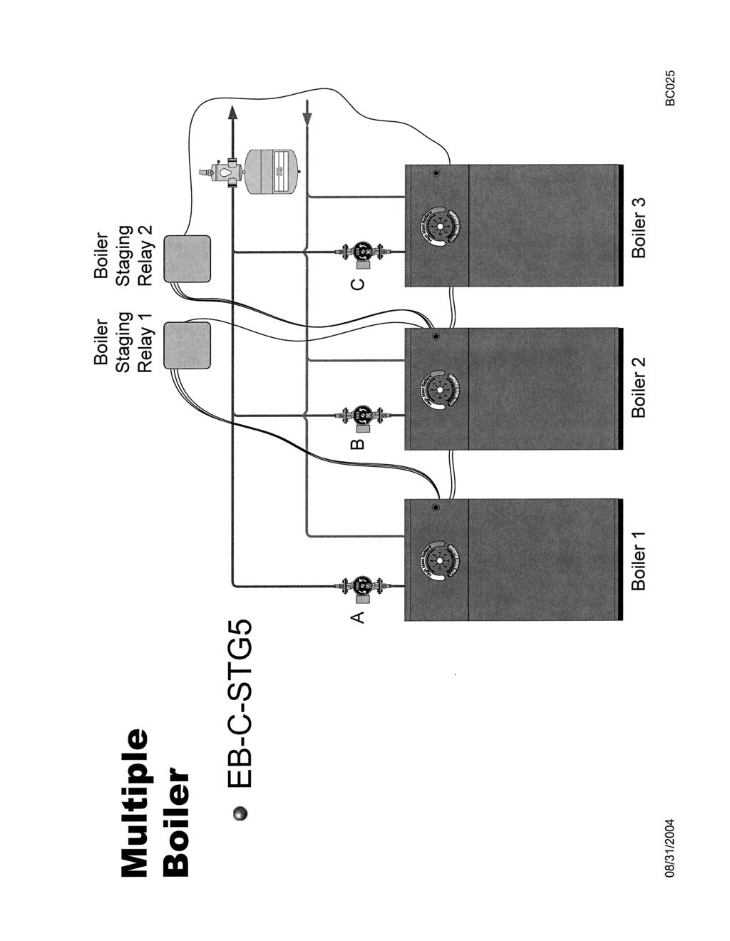
1 Multiple Boilers Electro TS Series Application EB-C-STG5 Drawings: BC025 BX404 BH504 XX017 Information All Electro-Boilers, except Mini-Boiler, have the same control board (EB5623**). The plug-in control chip (software) determines how this control board is used or configured for each product model number. There are three basic types or programs: EB-S-**, EB-MS-**, EB-C+-** control supply temperature is based upon a full stage (or element) switching on and off. EB-WA-**, EB-MA-** control supply temperature is based upon modulation of electric element to more accurately maintain the dial set supply temperature. EB-WO-**, EB-MO-** in addition to the above modulation control, the outdoor sensor provides for the WarmFlo concept which starts at a minimum or floor supply temperature and ramps up to a set point referencing 0 F. Additional definition or mix the commercial series (EB-C-**) uses staging and set-temperature concept. But with an option EB-CO-KIT it is also WarmFlo outdoor sensing (outdoor reset), see note below. Configuration 1. Attached BC025 illustrates the concept for parallel boilers. 2. The first or master boiler must have WarmFlo temperature set, modulation, capability (WA, MA, or EBCA), etc. Note: The EB-C-**-** series has factory shipped or default chip code EBCA to comply with this recommendation. However, if it was determined that this master boiler is outdoor reset, separate line item EB-CO-KIT will apply. 3. Using the above recommended model for the master boiler also provides built-in standby boiler capability, if needed. 4. Consecutive (slave) boilers can be S, MS, or C. However, WA or MA will provide less stage hunting and smoother operation for these consecutive boilers. 5. Utility load control is connected to the master boiler only. The slave boilers (second and consecutive) do not need a load control connection because these units cannot turn on when the master is in standby (SB mode). However, the slave boilers will continue to show the EL MODE amber LED on. Perhaps this may be interpreted as a conflict, but in this arrangement it represents the best and simplest hardware condition and presumably is acceptable. 6. The roomstat or control device is connected to the master boiler only. 7. One EB-C-STG5 (this option item) is required to link the master boiler to the next consecutive. A second and so on is needed for consecutive boilers. 8. If the installation is a single large zone, all operation is through the master unit R and W. Zone Configuration 1. A typical system arrangement is one or two large zones and the multiple boilers are typically sized to satisfy these large zones. However, there may also be several small zones (15,000, 30,000 Btu, etc.) which have individual room thermostats/pumps or zone valve and they do not require full boiler system capacity. In fact, they may not even require the full capacity of the master boiler. For this arrangement it is strongly recommended the Electro Industries zone controller be added to the system. a. EB-Z*A-* provides a configuration for zone pumps. 04/14/ BI505
 must be tied to zone input 2 or 3 or 4. 3. The zone controller capacity size dial switch must be set to F or G or H.")
2 b. EB-Z*S-* provides arrangement for zone valves at each zone. c. If there is more than one smaller zone, add-on EB-ZEA-2 or EB-ZES-2 will allow for additional small zones. 2. With this arrangement the large zone (main heating system) must be tied to zone input 2 or 3 or The zone controller capacity size dial switch must be set to F or G or H. These setting tell the multiple boiler system that the dial switch associated with large zone arrangements have no meaning. But the dial switch setting for zone 1 and the second zone board unit (-2 zones 5 through 8) will control the master boiler at the capacity setting for each specific zone (1, 5, 6, 7, 8). a. F zone 4 is large. b. G zone 3 or 4 are large c. H zone 2 or 3 or 4 are large. Installation Mechanical BX Boilers are plumbed in parallel. The master boiler unit should be closest to manifolds and distribution point. 2. Each boiler must have its own pump in its own pipe leg, before the paralleling connection. 3. The sum of these pumps can be viewed as the primary loop main pump. However, if this multiple boiler arrangement is for one large single zone, installer must discern that these pumps or even the first pump from the master boiler has adequate capacity. 4. Single expansion tank is adequate, but must be rated for the total system capacity. 5. Reference previous page on zone controller configuration and add appropriate zone controller. Installation Electrical 1. Element power is wired as specified in each individual boiler installation manual and drawings. 2. Each pump is wired and operated from its appropriate boiler as described in each boilers installation manual and drawing BH501, BH509, BH510, or BH Mount each EB-C-STG5 special relay next to main control board, within the length of the provided 3-wire pigtail cable. Do not extend this interconnect pigtail cable. 4. On the boiler main control board (door opened), approximately center left, are three small pins (marked J6 ). The special relay pigtail cable plugs into these three pins. Polarity is not required; simply make sure the header covers all three pins. 5. Reference drawing BH504, connect an additional wire from master unit W to the special relay W-IN and a separate wire from W-OUT to the next consecutive boiler W. 6. Reference drawing BH504, all commons from all boilers must be tied together. 7. Room thermostat or controlling device and utility load management are connected to the master boiler only as described in its installation manual. 8. Reference page 1 zone controller paragraph, use the installation manual associated with the specific zone controller and wire in the individual thermostats, pump/zone valves, etc. Note: Size switch is set to H for zone 4 handling of the main or large zone. Note: The 24-volt transformer within each boiler must have its primary wires connected to the control board with the same wire color or polarity for all units. This should be blue at the bottom or common and yellow at the 24VAC tab. It is important to recheck this factory assembly wiring or connection. 04/14/ BI505
3 WARNING DO NOT, UNDER ANY CIRCUMSTANCES, SIMPLY JUMPER ANY ONE OF THE BOILERS R TO W TO OPERATE AS A HOT BOILER SYSTEM. WARNING THE E TAB OR SENSOR BYPASS FUNCTION IS LIVE AND AVAILABLE ON EACH INDIVIDUAL BOILER. THIS IS INDEPENDENT AND HAS NOTHING TO DO WITH THIS STAGING ARRANGEMENT. THE TEST OR TROUBLESHOOTING E FUNCTION CAN BE USED ON ANY ONE OF THE BOILERS TO VERIFY ITS OPERATION, BUT DO NOT LEAVE A UNIT UNATTENDED WITH THE E TAB AT 24 VOLTS. Setup 1. See operations manual for each individual boiler and its setup requirements. 2. The master boiler should set for the best operating temperature associated with the smaller zones or any office usage from this system. 3. The consecutive boilers should all be set at the same temperature and typically select the temperature which would be required for the large zone or large heating capacity. Operating Sequence 1. The system is turned on with the thermostat or controlling device closing R to W on the master boiler only. If using EB-Z**-1 zone controller sending W-OUT to the master boiler, W will turn the system on. 2. The master stages up and controls its supply water temperature based upon its preset value. 3. If the master unit has all four stages on for 5 continuous minutes, it provides a W signal to the next consecutive boiler, via the EB-C-STG5 special relay. 4. The consecutive boiler stages up and controls its water supply temperature according to its program and its set value. 5. If the consecutive boiler has all four stages on for 5 minutes, it provides a W signal, via the second EB-C-STG5 special relay, to the next consecutive unit. 6. Steps 3, 4, and 5 repeat until the last boiler is on. 7. Utility load control performs its normal function (blue and blue/white wires) to the master unit only. With the load control in interrupt state, all consecutive boilers as well as the master boiler go into an interrupt mode. 8. Each boiler operates as described within its individual installation/operating manual. 9. If using EB-Z**-* zone controller, it operates as described in its appropriate installation/operating manual. See page 1, zone controller paragraph, in relation to large zone and setting the SIZE dial switch. 04/14/ BI505
4
5
6
7
8 Electro Industries, Inc. Limited Product Warranty Effective February 5, 2009 Electro Industries, Inc. warrants to the original owner, at the original installation site, for a period of two (2) years from date of installation, that the product and product parts manufactured by Electro Industries are free from manufacturing defects in materials and workmanship, when used under normal conditions and when such product has not been modified or changed in any manner after leaving the plant of Electro Industries. If any product or product parts manufactured by Electro Industries are found to have manufacturing defects in materials or workmanship, such will be repaired or replaced by Electro Industries. Electro Industries shall have the opportunity to directly, or through its authorized representative, examine and inspect the alleged defective product or product parts. Electro Industries may request that the materials be returned to Electro Industries at the owner s expense for factory inspection. The determination as to whether product or product parts shall be repaired, or in the alternative replaced, shall be made by Electro Industries or its authorized representative. Electro Industries will cover reasonable labor costs to repair defective product or product parts for ninety (90) days after installation. TWENTY YEAR (20) LIMITED WARRANTY ON BOILER ELEMENTS AND VESSELS Electro Industries, Inc. warrants that the boiler elements and vessels of its products are free from defects in materials and workmanship through the twentieth year following date of installation. If any boiler elements or vessels are found to have a manufacturing defect in materials or workmanship, Electro Industries will replace them. TWENTY YEAR (20) LIMITED WARRANTY ON SPIN FIN ELEMENTS Electro Industries, Inc. warrants that the spin fin elements of its products are free from defects in materials and workmanship through the twentieth year following date of installation. If any spin fin elements are found to have a manufacturing defect in materials or workmanship, Electro Industries will replace them. FIVE YEAR (5) LIMITED WARRANTY ON OPEN WIRE ELEMENTS Electro Industries, Inc. warrants that the open wire elements of its products are free from defects in materials and workmanship through the fifth year following date of installation. If any open wire elements are found to have a manufacturing defect in materials or workmanship, Electro Industries will replace them. Page 1 of 2 XX017
9 THESE WARRANTIES DO NOT COVER: 1. Costs for labor for removal and reinstallation of an alleged defective product or product parts, transportation to Electro Industries, and any other materials necessary to perform the exchange, except as stated in this warranty. Replacement material will be invoiced to the distributor in the usual manner and will be subject to adjustment upon verification of defect. 2. Any product that has been damaged as a result of being improperly serviced or operated, including, but not limited to, the following: operated with insufficient water or airflow, allowed to freeze, subjected to flood conditions, subjected to improper voltages or power supplies, operated with airflow or water conditions and/or fuels or additives which cause unusual deposits or corrosion in or on the product, chemical or galvanic erosion, improper maintenance or subject to any other abuse or negligence. 3. Any product that has been damaged as a result of natural disasters, including, but not limited to, the following: lightning, fire, earthquake, hurricanes, tornadoes or floods. 4. Any product that has been damaged as a result of shipment or handling by the freight carrier. It is the receiver s responsibility to claim and process freight damage with the carrier. 5. Any product that has been defaced, abused, or suffered unusual wear and tear as determined by Electro Industries or its authorized representative. 6. Workmanship of any installer of the product. This warranty does not assume any liability of any nature for unsatisfactory performance caused by improper installation. 7. Transportation charges for any replacement part or component, service calls, normal maintenance; replacement of fuses, filters, refrigerant, etc. CONDITIONS AND LIMITATIONS: 1. If at the time of a request for service the original owner cannot provide an original sales receipt or a warranty card registration then the warranty period for the product will have deemed to begin thirty (30) days after the date of manufacture and NOT the date of installation. 2. The product must have been sold and installed by a licensed electrical contractor, a licensed plumbing contractor, or a licensed heating contractor. 3. The application and installation of the product must be in compliance with Electro Industries specifications as stated in the installation and instruction manual, and all state and federal codes and statutes. If not, the warranty will be null and void. 4. The purchaser shall have maintained the product in accordance with the manual that accompanies the unit. Annually, a qualified and licensed contractor must inspect the product to assure it is in proper working condition. 5. All related heating components must be maintained in good operating condition. 6. All lines must be checked to confirm that all condensation drains properly from the unit. 7. Replacement of a product or product part under this limited warranty does not extend the warranty term or period. 8. Replacement product parts are warranted to be free from defects in material and workmanship for ninety (90) days from the date of installation. All exclusions, conditions, and limitations expressed in this warranty apply. 9. Before warranty claims will be honored, Electro Industries shall have the opportunity to directly, or through its authorized representative, examine and inspect the alleged defective product or product parts. Remedies under this warranty are limited to repairing or replacing alleged defective product or product parts. The decision whether to repair or, in the alternative replace, products or product parts shall be made by Electro Industries or its authorized representative. THESE WARRANTIES DO NOT EXTEND TO ANYONE EXCEPT THE ORIGINAL PURCHASER AT RETAIL AND ONLY WHEN THE PRODUCT IS IN THE ORIGINAL INSTALLATION SITE. THE REMEDIES SET FORTH HEREIN ARE EXCLUSIVE. ALL IMPLIED WARRANTIES, INCLUDING WARRANTIES OF MERCHANTABILITY AND FITNESS FOR A PARTICULAR PURPOSE, ARE HEREBY DISCLAIMED WITH RESPECT TO ALL PURCHASERS OR OWNERS. ELECTRO INDUSTRIES, INC. IS NOT BOUND BY PROMISES MADE BY OTHERS BEYOND THE TERMS OF THESE WARRANTIES. FAILURE TO RETURN THE WARRANTY CARD SHALL HAVE NO EFFECT ON THE DISCLAIMER OF THESE IMPLIED WARRANTIES. ALL EXPRESS WARRANTIES SHALL BE LIMITED TO THE DURATION OF THIS EXPRESS LIMITED WARRANTIES SET FORTH HEREIN AND EXCLUDE ANY LIABILITY FOR CONSEQUENTIAL OR INCIDENTAL DAMAGES RESULTING FROM THE BREACH THEREOF. SOME STATES DO NOT ALLOW THE EXCLUSION OR LIMITATION OF INCIDENTAL OR CONSEQUENTIAL DAMAGES, SO THE ABOVE LIMITATIONS OR EXCLUSIONS MAY NOT APPLY. PRODUCTS OR PARTS OF OTHER MANUFACTURERS ATTACHED ARE SPECIFICALLY EXCLUDED FROM THE WARRANTY. THIS WARRANTY GIVES YOU SPECIFIC LEGAL RIGHTS, AND YOU MAY HAVE OTHER RIGHTS WHICH VARY UNDER THE LAWS OF EACH STATE. IF ANY PROVISION OF THIS WARRANTY IS PROHIBITED OR INVALID UNDER APPLICABLE STATE LAW, THAT PROVISION SHALL BE INEFFECTIVE TO THE EXTENT OF THE PROHIBITION OR INVALIDITY WITHOUT INVALIDATING THE REMAINDER OF THE AFFECTED PROVISION OR THE OTHER PROVISIONS OF THIS WARRANTY. Page 2 of 2 XX017
BASIC INSTALLATION AND OPERATION MANUAL
 BASIC INSTALLATION AND OPERATION MANUAL EMDI ** *5 * Size H = 8W x 10D L = 8W x 16D kw Stages 10 = 9.6 kw 2 = 2 15 = 14.4 kw 3 = 3 20 = 19.2 kw NOTE: This Duct Heater may have various installation applications.
WF-DFSLT Dual Fuel Kit
 WF-DFSLT Dual Fuel Kit Trane/American Standard ComfortLink System and/or Roomstat 900 Controller Installation & Operating Instructions Reference WarmFlo Select plenum heater product EM-WU(WD)***D*-SLT
Electro Industries Make-Up Air II
 --------------------------------------------------------------------------------------- Installation & Operating Manual ---------------------------------------------------------------------------------------
ELECTRIC MAKE-UP AIR
 ELECTRIC MAKE-UP AIR WITH WARMFLO CONTROLLER EM-WM**3** 15 = 15 kw 20 = 20 kw 11 = 10 kw, 3-phase 5 = Single phase, 5 kw per stage 4 = 3-phase, 3-stage 6 = 3-phase, 3-stage H = 8w x 10d L = 8w x 16d Specific
First Year Limited Warranty for Residential Use Condensing Water Boilers (Includes Heat Exchanger and Component Parts)
") THIS GIVES THE ORIGINAL PURCHASER ONLY SPECIFIC LEGAL RIGHTS AND YOU MAY ALSO HAVE OTHER LEGAL RIGHTS WHICH VARY FROM STATE-TO-STATE AND -TO- Our Warranty By this warranty statement ( Limited Warranty
THIS GIVES THE ORIGINAL PURCHASER ONLY SPECIFIC LEGAL RIGHTS AND YOU MAY ALSO HAVE OTHER LEGAL RIGHTS WHICH VARY FROM STATE-TO-STATE AND -TO- Our Warranty By this warranty statement ( Limited Warranty
Whirlpool Bathtub Model Number: MT618
 INSTALLATION AND OWNER'S MANUAL Whirlpool Bathtub Model Number: MT618 Please carefully read these instructions before you begin to install the products. 07/11 Rev A P/N:100056-03 Thank you for purchasing
CONDENSING WATER BOILERS. (Models VLT , Q VX ,
 Our Warranty By this warranty statement ( Limited Warranty ), ECR International, Inc. ( ECR ) issues limited warranties from the date of installation of the applicable Dunkirk Boiler ( Boiler ) to the
INSTALLATION & OPERATING INSTRUCTIONS
 ELECTRO-BOILER TS Series INSTALLATION & OPERATING INSTRUCTIONS Model EB-S-13 EB-S-18 EB-S-23 EB-S-27 APPLICATION: This Electro-Boiler series is factory equipped with outlet temperature sensing and a smart
ELECTRO-BOILER. Commercial Series. INSTALLATION & OPERATING INSTRUCTIONS Model EB-C* Series
 ELECTRO-BOILER Commercial Series INSTALLATION & OPERATING INSTRUCTIONS Model EB-C* Series LOCATE EXACT NUMBER ON NAMEPLATE, LOCATE LINE ITEM ON PAGE 1 APPLICATION: This Electro-Boiler is factory equipped
INSTALLATION, OPERATION AND MAINTENANCE
 INLINE HEATER INSTALLATION, OPERATION AND MAINTENANCE MODELS: ILS SERIES 1.5kW 120V SINGLE PHASE BEFORE YOU BEGIN CHECK ALL ELECTRICAL CONNECTIONS TO ALL COMPONENTS WITHIN THE HEATER FOR TIGHTNESS. CONNECTIONS
WMWLB / WMWFM / WTWLB / WTWFM Series Hydronic Heating Unit
 January 2008 WMWLB / WMWFM / WTWLB / WTWFM Series Hydronic Heating Unit Installation Operation Maintenance The units are designed for permanent up flow, counter flow, or horizontal left or right airflow
Thermostat Remote Control & Receiver
 OWNER S MANUAL P/N 33CSIRRCVR-01 Thermostat Remote Control & Receiver Allows remote control operation of basic thermostat functions Unique Warmer & Cooler commands Compatible with thermostat models: 33CS450-01,
Spa Control System OWNER S MANUAL
 LIMITED WARRANTY ONE YEAR LIMITED WARRANTY: UNITED SPAS, INC. warrants, to the original purchaser, the Spa Equipment against defects in materials or workmanship for a period of one year from date of purchase.
Sentry LIQUID LEVEL CONTROLLER MODEL 120 OPERATING MANUAL.
 Sentry LIQUID LEVEL CONTROLLER MODEL 120 OPERATING MANUAL www.aquaticsentry.com TABLE OF CONTENTS 1. SAFETY PRECAUTIONS... 3 2. APPLICATION... 3 2.1 HIGH AND LOW LEVEL ALARM 2.2 PUMP DOWN CONTROLLER 2.3
be liable for any other loss or damage, whether direct, indirect, incidental or consequential.
 Integrated HydroStat 3200-Plus for Slant Fin Boilers Part No. 48-3200-03 and 48-3200-04 120 VAC Input / 24 VAC Burner Circuit PATENT S. 8.391,708; 7,891,572; 8,844,834; Others Pending INSTALLATION INSTRUCTIONS
ELECTRO-BOILER Commercial Series
 ELECTRO-BOILER Commercial Series INSTALLATION & OPERATING INSTRUCTIONS Model EB-CX Series APPLICATION: This Electro-Boiler is factory equipped with WarmFlo smart controller. WarmFlo automatically regulates
User s Manual and Warranty Information ThyssenKrupp Access
 User s Manual and Warranty Information ThyssenKrupp Access Welcome to your Destiny ThyssenKrupp Access would like to thank you for choosing the Destiny. You have purchased one of the finest residential
A2Z Ozone, Inc. PRODUCT MANUAL
 A2Z Ozone, Inc. PRODUCT MANUAL INSTALLATION & OPERATION MANUAL CE www.a2zozone.com Rev. 02142018 CONTENTS Page Important Safety Instructions... Specifications... Installation Instructions... 3 4 5 Troubleshooting...
Next Generation Corona Discharge Auto Voltage Sensing Installation Manual
 Next Generation Corona Discharge Auto Voltage Sensing Installation Manual 4-2122-01 Rev.B IMPORTANT SAFETY INSTRUCTIONS When installing and operating the Spa Eclipse ozone generator, basic precautions
DECORATIVE GAS LOG PLACEMENT INSTRUCTIONS
 DECORATIVE GAS LOG PLACEMENT INSTRUCTIONS REVOLUTION L-360-CD & L-420-CD SERIES If for any reason, you cannot follow these instructions, FOR ANY REASON WHATSOEVER, just return the product to your dealer,
User s Manual and Warranty Information for Counterweighted Chain Drive ThyssenKrupp Access
 II User s Manual and Warranty Information for Counterweighted Chain Drive ThyssenKrupp Access Part #2139703 Rev. G II Table of Contents Introduction...3 Elevator Overview...4 Description of Features...5-7
OPERATION & INSTALLATION MANUAL
 OPERATION & INSTALLATION MANUAL Model: SIO 14 & SIO 18 Electric Tankless Hot Water Generators Table of Contents SAFETY INFORMATION... 1 INTRODUCTION... 2 Unit Operation:... 2 Unit Freezing:... 3 Maintenance:...
INSTALLATION INSTRUCTIONS and OPERATING MANUAL. *Aquastat is a registered trademark of Honeywell International, Inc.
 MODEL 3200-Plus Temp Limit / LWCO Control with Thermal Targeting for Water Boilers 120 VAC Input / 24 VAC Burner Circuit PATENT. 8,931,708; 8,844,834; 7,891,572; others pending INSTALLATION INSTRUCTIONS
Carrier NON-PROGRAMMABLE DIGITAL THERMOSTAT. Dual Setpoint Thermoglow Backlight No Batteries Required Auto Changeover Locking Keypad
 Carrier Heating & Cooling TSTATCCNB00 NON-PROGRAMMABLE DIGITAL THERMOSTAT USER INFORMATION MANUAL FOR THE OPERATION AND MAINTENANCE OF YOUR NEW THERMOSTAT NON-PROGRAMMABLE DIGITAL THERMOSTAT AUTO 74 Dual
Installation and Owner Man u al
 T H R E E P H A S E Evaporator Fan Control System Installation and Owner Man u al WARNING The installation of this device should be done only by competent personnel, experienced in electrical wiring, and
5+2 DAY. OWNER S MANUAL Venstar Inc. 05/08
 Digital Thermostat residential THERMOSTAT 5+2 DAY PROGRAMMABLE up to 1-heat & 1-cool PUMP Stages: 1-Heat, 1-Cool Battery or System Powered Back-Lit Digital Display Fahrenheit or Celsius Service Filter
M1200 Series Limited Warranty Dependability Promise
 M1200 Series Limited Warranty Dependability Promise Warranty effective for equipment manufactured after January 1, 2011 Dear Customer, Congratulations on your decision to purchase the most reliable heating
Installation Instructions PP-AS20 Anti-Scale System
 Installation Instructions PP-AS20 Anti-Scale System THIS UNIT MUST BE INSTALLED BY A LICENSED PLUMBER TO VALIDATE THE WARRANTY. COMPONENTS PP-AS20 Filter Housing PP-AS20R Filter Cartridge Installation
INSTALLATION INSTRUCTIONS and OPERATING MANUAL. *Aquastat is a registered trademark of Honeywell International, Inc.
 MODEL 3200-Plus Temp Limit / LWCO Control with Thermal Targeting for Water Boilers 120 VAC Input / 24 VAC Burner Circuit PATENT. 7,891,572 INSTALLATION INSTRUCTIONS and OPERATING MANUAL Saves Fuel Features
Safety, Installation, and Operation Manual
 Automatic Steam Humidifier Control Safety, Installation, and Operation Manual READ COMPLETE INSTALLATION INSTRUCTIONS BEFORE STARTING. WARNING This product must be installed by a qualified heating and
Sentry LIQUID LEVEL GAUGE MODEL 200 or 200C OWNER MANUAL REV 1.7 SEPT08 PAGE 1 OF 12
 PAGE 1 OF 12 TABLE OF CONTENTS PAGE 1. SAFETY PRECAUTIONS 1.1. Electrical shock 3 2. APPLICATION 3 3. INSTALLATION 3.1. Mount indoor alarm display 3.2. Mount the outdoor junction box 3.3. Install interconnecting
VENSTAR T1070 FAN COIL THERMOSTAT PROGRAMMABLE 2 OR 4 PIPE SYSTEMS OWNER S MANUAL AND INSTALLATION INSTRUCTIONS
 VENSTAR FAN COIL THERMOSTAT FAN COIL THERMOSTAT T1070 NON- PROGRAMMABLE 2 OR 4 PIPE SYSTEMS Remote sensor ready 3 speed fan control Self-prompting adjustment Auto 2-pipe changeover when used with ACC-SENFC
Ion Genesis II Pump Controller Digital Level Control with Pump Alternation and High Water Alarm
 Page 1 of 8 General Overview Thank you for purchasing an Ion Genesis controller. Take the time to read the instructions carefully before using this appliance. We strongly recommend that you keep this instruction
Humidity Module OWNER S MANUAL. Complete Control from
 OWNER S MANUAL P/N 33CSHUMID-01 When installed, the thermostat may have* the ability to: Control a compatible humidifier Display relative humidity level as measured at the thermostat Dehumidify (Cool to
LV-5 Direct Contact Low Voltage Detector and LV-5/K01 Kit including LV-PT Tester, Holster and Available Accessories
 LV-5 Direct Contact Low Voltage Detector and LV-5/K01 Kit including LV-PT Tester, Holster and Available Accessories Operating & Instruction Manual 1475 Lakeside Drive Waukegan, Illinois 60085 U.S.A. 847.473.4980
Electro-HELPS XV ELECTRO-BOILER SPECIFICATIONS. A complete product line to fi t all your application needs. Made in USA
 Electro-HELPS XV Made in USA ELECTRO-BOILER SPECIFICATIONS A complete product line to fi t all your application needs The Electro-Boiler has been heating America s homes and businesses since 980. We take
IAQ Series. Bosch IAQ Photo Catalytic Oxidizer (PCO) Residential Application. Installation Manual and Owner s Guide
 Residential Application. Installation Manual and Owner s Guide") Installation Manual and Owner s Guide IAQ Series Bosch IAQ Photo Catalytic Oxidizer (PCO) Residential Application PCOB-09012-0--A - 9" PCO BULB PCOB-14024-0--A - 14" PCO BULB 67202220344 Revised 07-12
Installation Manual and Owner s Guide IAQ Series Bosch IAQ Photo Catalytic Oxidizer (PCO) Residential Application PCOB-09012-0--A - 9" PCO BULB PCOB-14024-0--A - 14" PCO BULB 67202220344 Revised 07-12
Sentry LIQUID LEVEL ALARM MODEL 100 OPERATING MANUAL.
 Sentry LIQUID LEVEL ALARM MODEL 100 OPERATING MANUAL www.aquaticsentry.com TABLE OF CONTENTS 1. SAFETY PRECAUTIONS... 3 2. APPLICATION... 3 2.1 HIGH Liquid Level Alarm 2.2 LOW Liquid Level Alarm 3. INSTALLATION...
PIR Sensor. User s Guide
 User s Guide 2760347 PIR Sensor Thank you for purchasing your PIR Sensor from RadioShack. Please read this user s guide before setting up and using your new sensor. Attention: Observe precautions for handling
FOR EASY, FAST INSTALLATION AND FOR RESULTS
 Page 1 INSTALLATION & OPERATING INSTRUCTIONS FOR FEDERAL FLOOR FURNACE OFB-100 AND OFB100L UNPACK SHIPMENT CAREFULLY AND INSPECT FOR DAMAGE. ALL GOODS ARE CAREFULLY MANUFACTURED, INSPECTED, CHECKED, AND
DIGITAL STEEL FIRE & SECURITY
 Models 2111-2115 DIGITAL STEEL FIRE & SECURITY Read this manual carefully and never store it inside the safe! Digital Steel Fire & Security Safe Models 2111-2115 PACKAGE CONTENTS 1 Digital Steel Fire &
Operation & Installation Guide
 ENGLISH Operation & Installation Guide Office / Security Safes with Key Lock DUPLICATE KEYS ARE NOT AVAILABLE FOR THESE SAFES Models 5410, 5440, 5445, 5465 Read this manual carefully and never store it
Ion Endeavor Pump Controller Digital Level Control with Pump Alternation and High Water Alarm
 Ion Endeavor Controller Digital Level Control with Alternation Page 1 of 8 General Overview The Ion Endeavor is a pump controller that senses a water level of up to 72", has a configurable water level/pump
INSTALLATION INSTRUCTIONS
 INSTALLATION INSTRUCTIONS FOR AQUECOIL HYDRONIC HEATING UNITS GENERAL INFORMATION The AQUECOIL Hydronic Heating Unit is offered in many different capacities and physical configurations in order to match
Installation and Operations Manual
 Installation and Operations Manual H-IM-LLC February 2018 Part No. 25092501 Replaces H-IM-LLC (01/2014) Lead Lag Control System Table of Contents General Safety Information 2 Inspection 2 Warranty Statement
Thin Window FAN With Comfort Control Thermostat. Instruction Leaflet. pure indoor living MODEL: BWF0522M-CN
 pure indoor living Thin Window FAN With Comfort Control Thermostat MODEL: BWF0522M-CN Instruction Leaflet Read instructions before operating. Retain for future reference. Questions? Comments? Call 1-800-253-2764
AUTO SPEED BLENDER INSTRUCTION MANUAL MODEL: BLCLMB1
 AUTO SPEED BLENDER INSTRUCTION MANUAL MODEL: BLCLMB1 1 TABLE OF CONTENTS IMPORTANT SAFEGUARDS 3 POLARIZED PLUG 4 PRODUCT DIAGRAM 5 USAGE INSTRUCTIONS PREPARING YOUR AUTO SPEED BLENDER FOR USE 6 HOW TO
ELECTRIC FIREPLACE OWNER S MANUAL
 ELECTRIC FIREPLACE OWNER S MANUAL MODELS EL1346C 4001358 WARNING: If the information in this manual is not followed exactly, a fire or electrical shock may result causing property damage, personal injury
Easy installation in both new construction and retrofit. ZB90C ZB110C X2 Multi-Speed Ventilation Fan INSTALLATION GUIDE
 READ AND SAVE THESE INSTRUCTIONS Installer: leave this guide with homeowner. Register your product online at www.broan.ca/register.asp. ZB90C ZB0C X Multi-Speed Ventilation Fan INSTALLATION GUIDE Easy
Thermostat Series. Installation Manual TSTBM-RRS--TW-A Revised 02-13
 Installation Manual Thermostat Series TSTBM-RRS--TW-A Remote Temperature Sensor (Requires TSTBM3H2CPH6W-A) TSTBM-RRS--TW-A 2 TSTBM-RRS--TW-A Table Of Contents Table of Contents Thermostat Quick Reference...
OWNER'S MANUAL T0140. Contents Page #
 Digital Thermostat residential THERMOSTAT T0140 NON- PROGRAMMABLE up to 2-heat & 1-cool PUMP Stages: 2-Heat, 1-Cool Battery or System Powered Auxiliary Heat Indicator Fahrenheit or Celsius Bi-Color LED
Ella Gel Coat Walk In Tub E SERIES OWNER'S MANUAL
 Ella Gel Coat Walk In Tub E SERIES OWNER'S MANUAL REPRESENTING THESE MODEL NUMBERS: 26 x 52 E2645SL / E2645SR SOAKING E2645AL / E2645AR AIR MASSAGE E2645DL / E2645DR DUAL MASSAGE 30 x 48 E3048SL / E3048SR
DIGITAL STEEL FIRE & SECURITY
 Models 2111-2115 DIGITAL STEEL FIRE & SECURITY Read this manual carefully and never store it inside the safe! Digital Steel Fire & Security Safe Models 2111-2115 PACKAGE CONTENTS 1 Digital Steel Fire &
MDV. Mixing Degas Vessel. For Spa Ozone Generators Installation & Operations Manual Rev.C
 MDV Mixing Degas Vessel For Spa Ozone Generators Installation & Operations Manual 4-0642 Rev.C Table of Contents SECTION 1 General Information... 1 SECTION 2 Mounting the MDV and GAC Cartridge... 1 SECTION
MODEL TSTATBBPB101 PROGRAMMABLE DIGITAL THERMOSTAT. Heat Pump & Heat Cool. Meets California Title 24 Residential USERS INFORMATION MANUAL
 USERS INFORMATION MANUAL Heating & Cooling Systems L TSTATBBPB101 PROGRAMMABLE DIGITAL THERMOSTAT NOTE TO INSTALLER: This manual must be left with the equipment user. AUTO Heat Pump & Heat Cool Dual Setpoint
TC --- NHP, TC --- NAC Comfort Series Non---Programmable Thermostat. Owner s Manual
 TC --- NHP, TC --- NAC Comfort Series Non---Programmable Thermostat Owner s Manual YOU WILL LOVE THIS THERMOSTAT. This Comfortt non -programmable thermostat is an easy to use model that provides the most
5+2 DAY PROGRAMMABLE DIGITAL THERMOSTAT
 Heating & Cooling TSTATCCPQ501 PROGRMABLE DIGITAL THERMOSTAT USER INFORMATION MANUAL FOR THE OPERATION AND MAINTENANCE OF YOUR NEW THERMOSTAT SINGLE STAGE HEAT & COOL THERMOSTAT 72 Tu I2:00 72 prog 5+2
ELECTRO-BOILER. Midsize INSTALLATION & OPERATING INSTRUCTIONS
 ELECTRO-BOILER Midsize INSTALLATION & OPERATING INSTRUCTIONS Model EB-MO-10 EB-MO-15 EB-MO-20 APPLICATION: This Electro-Boiler is factory equipped with WarmFlo smart controller. WarmFlo automatically regulates
Safety & Installation Instructions
 Model 6303 & 6302 Zoned Comfort Control Safety & Installation Instructions READ AND SAVE THESE INSTRUCTIONS 61001212A 6302-6303 Zoned Comfort Control Install.indd 1 TABLE OF CONTENTS SAFETY INSTRUCTIONS..........................................
Safety & Installation Instructions
 Model 6203 & 6202 Zoned Comfort Control Safety & Installation Instructions READ AND SAVE THESE INSTRUCTIONS 61001213A 6202-6203 Zoned Comfort Control Install.indd 1 TABLE OF CONTENTS SAFETY INSTRUCTIONS..........................................
20 INCH ELECTRIC GRIDDLE
 20 INCH ELECTRIC GRIDDLE USER GUIDE Now that you have purchased a Chefman product you can rest assured in the knowledge that as well as your 3-year parts and labor warranty you have the added peace of
14+ SEER R-410a AIR CONDITIONERS. Aluminum Coil Series. Efficiencies up to 14+ SEER/12 EER. Nominal Sizes Ton. Capacities 16.
 14+ SEER R-410a Coil Company, L.P AIR CONDITIONERS UNITED STATES PATENT #D557,394S #D557,395S R-410A Aluminum Coil Series Efficiencies up to 14+ SEER/12 EER Nominal Sizes 1.5-5 Ton Capacities 16.6 to 56
SPA BLOWER OWNER'S MANUAL XXXX, XXXX, XXXX, XXXX, XXXX, XXXX fax
 SPA BLOWER OWNER'S MANUAL 80015-XXXX, 80016-XXXX, 80017-XXXX, 80018-XXXX, 80019-XXXX, 80020-XXXX fax 888.610.3839 2015 323300-015 6/15 THIS PAGE INTENTIONALLY LEFT BLANK. 2 Operating Instructions and Parts
INSTALLATION & OPERATION MANUAL
 INSTALLATION & OPERATION MANUAL Model TME- * * Balance of model number is determined by customer specifi ed limits and Setbacks. AUTOMATIC SETBACK THERMOSTAT LIGHT SENSING OR CONTACT CLOSURE FOR LOW VOLTAGE
Instruction Leaflet. Read instructions before operating. Retain for future reference.
 pure indoor living Mini TOWER FAN MODEL: BT014 Series Instruction Leaflet Read instructions before operating. Retain for future reference. Questions? Comments? Call 1-800-253-2764 in North America or visit
OPERATING INSTRUCTIONS
 OPERATING INSTRUCTIONS FLOSENTRY 3 MFFS3 PVC & CPVC FLOW METER (877) 356-5463 (p) 330-331-7331 (f) 330-331-7172 www.flo-corp.com 2017 FLO-CORP REVA 1116 1 DESCRIPTION Compatible with most MEMFlo meters,
MCD. Corona Discharge Ozone Generators MANUFACTURED BY Bullock Lane San Luis Obispo, CA
 MCD Corona Discharge Ozone Generators MANUFACTURED BY 3428 Bullock Lane San Luis Obispo, CA 93401 4-0622 Copyright 2005 DEL Ozone, Inc. IMPORTANT SAFETY INSTRUCTIONS When installing and using DEL Models
Non-Programmable Digital Thermostat
 OWNER'S MANUAL MODEL P474-0140 Non-Programmable Digital Thermostat HEAT PUMP THERMOSTAT 2 HEAT, 1 COOL emergency aux. heat normal energy save Fan On Fan Auto Millivolt Compatible Battery or System Powered
Carbon Monoxide (CO) Detecting Ventilation Fan Controller Model 120VC Single Relay (100/25 PPM) (200/35 PPM)
 Detecting Ventilation Fan Controller Model 120VC Single Relay (100/25 PPM) (200/35 PPM)") Carbon Monoxide (CO) Detecting Ventilation Fan Controller Model 120VC Single Relay 905-0005-01 (100/25 PPM) 905-0005-02 (200/35 PPM) 1. INTRODUCTION Your COSTAR VC carbon monoxide detecting ventilation
Carbon Monoxide (CO) Detecting Ventilation Fan Controller Model 120VC Single Relay 905-0005-01 (100/25 PPM) 905-0005-02 (200/35 PPM) 1. INTRODUCTION Your COSTAR VC carbon monoxide detecting ventilation
Easy installation in both new construction and retrofit
 READ AND SAVE THESE INSTRUCTIONS Installer: leave this guide with homeowner. Register your product online at www.broan.com/register. XB50L XB80L XB0L X Single-Speed Ventilation Fan with Light and Night
Digital Refrigerator/Freezer Thermometer model 00986
 Instruction Manual Digital Refrigerator/Freezer Thermometer model 00986 CONTENTS Unpacking Instructions... 2 Package Contents... 2 Product Registration... 2 Features & Benefits: Sensors... 2 Features &
User s guide RUH series Economical unit heater Replacement component list included
 www.stelpro.com User s guide RUH series Economical unit heater Replacement component list included This unit complies with the CSA and UL standards For further information or to consult this guide on line,
BIONAIRE HEATER. Instruction Leaflet. pure indoor living MODEL: BCH4130. Read instructions before operating. Retain for future reference.
 pure indoor living BIONAIRE HEATER MODEL: BCH4130 Instruction Leaflet Read instructions before operating. Retain for future reference. Questions? Comments? Call 1-800-253-2764 in North America. PLEASE
Programmable 5-2 Day Digital Thermostat
 Programmable 5-2 Day Digital Thermostat 1 STAGE HEAT COOL THERMOSTAT TOTALINE 72 72 prog run off set Tu Heat I2:00 next SINGLE STAGE HEAT PUMP COMPATIBLE (Does not control auxiliary heat) Separate programs
MaxLite LED Vapor Tight Linear Fixture
 General Safety Information To reduce the risk of death, personal injury or property damage from fire, electric shock, falling parts, cuts/abrasions, and other hazards read all warnings and instructions
OPERATION, SERVICE & PARTS MANUAL
 OPERATION, SERVICE & PARTS MANUAL BROASTER 620NXP & 621 EASY BREADER Be sure ALL installers read, understand, and have access to this manual at all times. MODEL 620NXP MODEL 621 Genuine Broaster Chicken,
Panel Mounted Heat Exchangers by Dantherm, Inc.
 Panel Mounted Heat Exchangers by Dantherm, Inc. PRODUCT INFORMATION MANUAL C0028 003 Pinnacle OM Manual Rev AB Page 1 of 14 Dantherm, Inc. 110 Corporate Drive, Suite K Spartanburg, SC 29303 Tel # +1 864
Projection Alarm Clock USER GUIDE
 Projection Alarm Clock USER GUIDE Jazwares, Inc. 2012 CONTENTS Please read the instructions along with the Alarm Clock carefully before you use it, so that you can operate it conveniently. WELCOME, Warnings
INSTALLATION INSTRUCTIONS and OPERATING MANUAL. *Aquastat is a registered trademark of Honeywell International, Inc.
 MODEL 3200-Plus Temp Limit / LWCO Control with Thermal Targeting for Water Boilers 120 VAC Input / 24 VAC Burner Circuit PATENT. 8,931,708; 8,844,834; 7,891,572; others pending INSTALLATION INSTRUCTIONS
Installation Operating Maintenance
 PROFILE SERIES PSU10, PSU15, PSU23, PSU30 PSU40 Installation Operating Maintenance Please read these instructions thoroughly before beginning your installation! The Profile series fan convectors are designed
Installation Manual. Expansion Module 0100 Version 1.0 EXP HBX Control Systems Inc.
 Installation Manual 000 Version.0 EXP-000 HBX Control s Inc. Control s Inc. HBX EXP 000 Version.0 HBX EXP-000 EXPANSION MODULE INTRODUCTION The EXP-000 is designed to be integrated with the HBX CPU-000
5+2 DAY. Digital Thermostat. residential. & 1-cool. up to 2-heat PROGRAMMABLE THERMOSTAT. Venstar Inc. 05/08
 Digital Thermostat residential THERMOSTAT 5+2 DAY PROGRAMMABLE up to 2-heat & 1-cool HEAT PUMP Stages: 2-Heat, 1-Cool Battery or System Powered Auxiliary Heat Indicator Back-Lit Digital Display Fahrenheit
I2:00 Mo MODEL TSTATBBPB501 PROGRAMMABLE DIGITAL THERMOSTAT. Heat Pump & Heat Cool. Meets California Title 24 Residential USERS INFORMATION MANUAL
 USERS INFORMATION MANUAL Heating & Cooling Systems L TSTATBBPB501 PROGRAMMABLE DIGITAL THERMOSTAT NOTE TO INSTALLER: This manual must be left with the equipment user. Mo 72 74 AUTO HEAT 70 Heat Pump &
Fan Speed. Auto Swing. Timer. Power. Mode. Fan. Only. Saver. Temp. Dry. Fan. Speed. Auto Swing. Timer. Power. Mode. Saver. Only. Temp.
 Mode 0F Cool Dry Temp Fan Speed Timer 0n/0ff Money Saver Mode 0F hr Fan Cool Only Dry Temp Auto Swing Power Fan Speed hr Timer 0n/0ff Money Saver Fan Only Auto Swing Power For inner cleaning, contact
SFH136-CN TRUSTED FOR OVER 100 YEARS. Sunbeam Heater. Instruction Leaflet PLEASE READ AND SAVE THESE IMPORTANT INSTRUCTIONS
 TRUSTED FOR OVER 100 YEARS SFH136-CN Sunbeam Heater Instruction Leaflet PLEASE READ AND SAVE THESE IMPORTANT INSTRUCTIONS PLEASE READ AND SAVE THESE IMPORTANT SAFETY INSTRUCTIONS When using electrical
FLCH4R Garage and Utility Electric Heater
 FLCH4R Garage and Utility Electric Heater Installation, Operation & Maintenance Instructions Model No. Volts Amps Watts BTU/HR Phase High Low High Low High Low Min Fuse Size* FLCH4R 208 17.3 8.66 3600
IW-25-2 Dehumidifier Installation & Operations. Manual
 IW-25-2 Dehumidifier Installation & Operations Installation and Operation Manual Manual IW-25-1 Dehumidifier Please Read and Save These Instructions Please Read and Save These Instructions Innovative Dehumidifier
Installation Instructions
 EZXCAB Sizes 016 and 020 High Efficiency Air Filtration System Installation Instructions JAN High Efficiency Air Filtration System Fig. 1 - EZXCAB C04001 NOTE: Read the entire instruction manual before
WIRING DIAGRAMS R410A MODELS PAC 2OAC/2OACH CAC OWC PWC
 WIRING DIAGRAMS R410A MODELS 2OAC/2OACH PAC CAC PWC OWC WIRING 02172017 TABLE OF CONTENTS PAGE 2OACH Deluxe Portable Air-cooled Heat Pump Electronic Controller... 2-3 Piping Schematic... 4 Single Phase
INTELLICRISP WAFFLE MAKER INSTRUCTION MANUAL MODEL: CKCLWF1. Calphalon_WaffleMaker_IB_SPEC_DarkGrey_CKCLWF1_19EM1.indd 1 1/25/19 09:30
 INTELLICRISP WAFFLE MAKER INSTRUCTION MANUAL MODEL: CKCLWF1 1 Calphalon_WaffleMaker_IB_SPEC_DarkGrey_CKCLWF1_19EM1.indd 1 1/25/19 09:30 TABLE OF CONTENTS IMPORTANT SAFEGUARDS 3 POLARIZED PLUG 4 PRODUCT
RATIO:GUARD Model E-1S EC Monitor
 EC probe Probe tees Probe retention clips Temperature probe E-1S monitor box UNPACKING Please open and inspect your package upon receipt. Your package was packed with great care and all the necessary packing
C L E A N I N G / M A I N T E N A N C E WA R R A N T Y I N F O R M AT I O N CLEANING/MAINTENANCE FAN STORAGE 3 YEAR LIMITED WARRANTY INSTRUCTIONS
 pure indoor living 16-INCH (41 CM) STAND FAN MODEL: BSF1016RT-CN Instruction Leaflet Read instructions before operating. Retain for future reference. Questions? Comments? Call 1-800-253-2764 in North America.
AG Series Electric Heaters
 AG Series Electric Heaters Auxiliary Electric Heat Installation, Operation & Maintenance Instructions 97B0005N04 Table of Contents Overview 3 Vertical Upflow or Downflow Installation - Internal 3 Vertical
Installation Manual. Detector Bases: PAD100-IB, PAD100-RB & PAD100-SB
 - + - + - + 1. Description This document provides instructions for mounting and wiring the Detector Bases PAD100-, PAD100-RB and PAD100-SB. The following detectors are compatible with Detector Bases PAD100-,
Compact Equipment Warranty Policy
 006 07.15 Compact Equipment Warranty Policy 07/2015 Table of Contents Preface Page 1 Distributor s Warranty Responsibilities Page 1 Standard Warranties Page 2 Warranty Coverage Page 2 Warranty Limitations
IN-GROUND SUBWOOFER INSTRUCTION MANUAL LS12T SUB LS15T SUB
 IN-GROUND SUBWOOFER INSTRUCTION MANUAL LS12T SUB LS15T SUB Introduction Thank you for purchasing a SLS Subwoofer. When properly installed, this subwoofer will provide you with years of outdoor entertainment
Owner s Manual. Digital. Heat Pump. 5+2 Day Programmable. Model S1-THEH21P5S HVAC SERVICE PARTS TM
 Owner s Manual Model S1-THEH21P5S HVAC SERVICE PARTS TM Heat Pump 5+2 Programmable Digital T h e rm ostats t a t BACKLIT DISPLAY Use with most Heat Pump systems: 1-Heat, 1-Cool 2-Heat, 1-Cool Control up
Air Pump Up to 800 gallons
 Air Pump Up to 800 gallons REMINDER CALL 1-888-755-6750 BEFORE RETURNING TO STORE. PACKAGE CONTENTS ITEM #PBPAPK40W Questions, problems, missing parts? Before returning to your retailer, call our customer
Installation and Service Manual. In-Floor Warming Module external desuperheater for 3rd party air source heat pumps
 Installation and Service Manual IFM-Series In-Floor Warming Module Model Size 48 In-Floor Warming Module external desuperheater for 3rd party air source heat pumps Maritime Geothermal Ltd. P.O. Box 2555
INSTALLATION & OPERATING INSTRUCTIONS MODEL #17900 KEGERATOR MANUAL
 INSTALLATION & OPERATING INSTRUCTIONS MODEL #17900 KEGERATOR MANUAL TABLE OF CONTENTS PAGE # SAFETY INSTRUCTIONS......... 2 INSTALLATION INSTRUCTIONS................... 3 CABINET LOCATION GUIDELINES...