Synco 900 Operating instructions
|
|
|
- Melvin Welch
- 6 years ago
- Views:
Transcription


1 Synco 900 Operating instructions Edition 2.0 Controller series B CE1B2707en
2
3 We congratulate you on the selection of the Siemens Synco 900 system and thank you for your purchase of the central apartment unit! The present Operating Instructions describe how to operate the central apartment unit and the other system components. Symbols used The symbols appearing on the display of the central apartment unit are explained in section Symbols on the display on page 18. In addition, the following symbols are used in this document: This symbol draws your attention to important information which must be observed to ensure safe operation of plant. The info symbol refers to additional information, notes and practical tips regarding settings and operation of the various units and the system. This symbol refers to disposal notes. Siemens Schweiz AG Building Technologies Group International Headquarters Gubelstrasse 22 CH-6301 Zug Tel Fax Siemens Switzerland Ltd Subject to change 3/80 Building Technologies
4 Contents Safety notes...8 System overview...9 System functions...9 Central unit...9 Heating control...9 DHW heating...10 Release of ventilation...10 Weather station...11 Light and blinds control...11 Supervisory functions...12 Alarms...12 Supervision of devices...12 System components...13 Central apartment unit QAX Operating elements...15 Display...17 Operation...20 Quiescent picture...20 Info pages...20 Menu level...21 Setting principle...21 Access levels...23 Settings...24 General...24 Absence...24 Supervision...25 Heating...26 Apartment timer function...26 Apartment operating mode...26 Apartment operating mode switch...27 Summer operation of heating...27 State of winter operation / summer operation...27 Beginning of summer / end of summer...28 Summer / winter changeover temperature...28 Antilime function...28 Room operating modes...29 State of room operating mode...29 Reason for room operating mode...29 Room operating mode during absence...30 Room temperature setpoints /80 Building Technologies Contents
5 Readjustment of room unit...31 Setting the time switch of a room...31 Actual value of the room temperature...33 Room temperature setpoint...33 Setpoint limitation...33 Valve position...33 Apartment timer influence...34 Optimum start / stop control...34 Room temperature supervision...35 Window airing function...36 Silent mode...36 Actuator calibration...37 Sensor readjustment...37 DHW...38 DHW operating mode...38 Forced DHW charging...38 State of DHW operating mode...38 Reason for DHW operating mode...38 DHW operating mode during absence...39 DHW temperature setpoint...39 DHW time switch...39 Actual value of the DHW temperature...40 DHW temperature setpoint...40 Operating state of charging pump and electric immersion heater...40 Plant operation...40 Reason for DHW plant operation...40 Limitation of charging time...40 Changeover to electric immersion heater...41 Supervision of the DHW temperature...41 Switching groups...41 Operating the switching groups...41 Scenes...42 Triggering switching groups via an event...43 Time switch for switching groups...45 Time switch release...45 Time switch for simulation of presence...46 Activating simulation of presence...46 Holidays/special days...49 Setting holidays / special days...49 Holidays and absence simultaneously...50 Room operating mode during holidays...50 DHW operating mode during holidays /80 Building Technologies Contents
6 Time settings...51 Date / time of day...51 Faults...51 Error / fault status messages...51 Fault status messages bus...51 Acknowledging faults...52 Inputs / outputs...52 Displaying input signals...52 Displaying output states...52 Settings...53 Language...53 Elevation above sea level...53 Time-of-day format...53 Backlit display / display contrast...53 Display format...54 Temperature display...54 Password for the service level...55 Direct selection of info pages...55 Fault inputs Fault outputs 1 and Supervision delay...58 Release of supervision...58 Event buzzer and status output...61 Signal duration...61 Plant name...62 Room names Switching group names Door names Lamp names Info lines...62 Room unit QAW Operation...63 Room operating modes...63 Room timer function...64 Readjustment of the room temperature setpoint...65 Display...65 Error messages...67 Maintenance...68 Monitor batteries...68 Room unit QAW Door / window contact wave AP DELTA reflex smoke detector /80 Building Technologies Contents
7 Manual capacity check...68 Replace batteries...69 Room unit QAW910, room sensor QAA910 and meteo sensor QAC Radiator control actuator SSA Door / window contact wave AP 260 and DELTA reflex smoke detector...71 Binding tests...72 Function button on the room unit, room sensor, meteo sensor, radio repeater and radiator control actuator72 Function button on the heating circuit controllers RRV912 and RRV Maintenance and cleaning...73 Disposal...73 Index /80 Building Technologies Contents
8 Safety notes Product liability The products may only be used in building services plant and only on the applications described Local safety regulations (installation, etc.) must be complied with Do not open the devices. If not observed, warranty by Siemens becomes void If a device is defective or damaged, immediately disconnect it from power and replace it Application-related technical data are only guaranteed in connection with the Siemens Synco 900 system. When using products of other manufacture not specified by Siemens, functionality must be ensured by the user. In that case, Siemens will not render any services and will not provide any warranty 8/80 Building Technologies Safety notes
9 System overview System functions The Synco 900 system offers you a host of choices. In addition to room climate and DHW heating control, the system enables you to control lights and blinds and to monitor fire detectors and door / window contacts. Central unit Central apartment unit QAX910 The heart of the system is the QAX910 central apartment unit. It facilitates operation of the entire system and ensures communication between the different devices. Heating control The central apartment unit has 12 individually adjustable 7-day time switches which are used to operate up to 12 different rooms. Each of these time switches can be programmed for operation at 3 different levels (Comfort, Precomfort and Economy) with 6 switching times. All rooms are combined to one apartment for which the operating mode and a holiday / special day program can be set. The central apartment unit collects the heat requests from the various rooms to deliver the total heat request to the heat generation controller. It transmits the actual values of the room temperatures and the room temperature setpoints to the heating circuit controllers and radiator control actuators which then calculate the positioning signals required for the actuators. The positioning signals for the multifunctional relays of the heating circuit controllers are generated by the central apartment unit. For room temperature control, the following system components are available: Room unit QAW910 On the room unit, the required room operating mode can be selected, the room setpoint temperature readjustment can be made, and the room timer function can be set. The room unit also acquires the current room temperature. All data are transmitted to the central apartment unit via radio. Room temperature sensor QAA910 The sensor acquires the room temperature and sends it to the central apartment unit via radio signal. 9/80 Building Technologies System overview

10 Heating circuit controllers RRV912 and RRV918 The controllers receive the setpoints and actual values of the various rooms from the central apartment unit (via radio signal) and forward the resulting positioning signals to the wirebound actuators. They also facilitate the direct connection of an apartment pump and of DHW heating. Radiator control actuator SSA955 The actuator receives the setpoint and the actual value (provided a room sensor or room unit is present) of the respective room from the central apartment unit via radio signal and readjusts the radiator valve accordingly. If no room sensor or room unit is installed, the radiator control actuator uses its own measured value of the room temperature as the actual value. Door / window contact wave AP 260 When a door or window is left open, the stroke of the radiator valves in the respective room is limited to the current position in order not to waste energy. The function acts on the wirebound actuators used with the RRV912 / RRV918 heating circuit controllers and the wireless SSA955 radiator control actuators. DHW heating The central apartment unit controls DHW heating of a locally connected DHW storage tank or facilitates remote operation of a DHW storage tank connected to the heat generation controller or some other central apartment unit. For that purpose, the central apartment unit is equipped with a DHW 7-day time switch with 6 switching times for changeover between Normal mode and Reduced mode. The central apartment unit can also be used for triggering manual forced charging of the DHW storage tank. The current DHW temperature appears on the display of the central apartment unit. Release of ventilation Relays can be used to enable or disable ventilation stages. Ventilation is enabled with the help of switching groups. 10/80 Building Technologies System overview
11 Weather station The central apartment unit receives the outside temperature and the atmospheric pressure from the meteo sensor. Meteo sensor QAC910 The meteo sensor acquires the outside temperature and the absolute atmospheric pressure and transmits both via radio signal to the central apartment unit. The current measured values of outside temperature and atmospheric pressure as well as the pressure trend can be shown in the quiescent picture. The change of atmospheric pressure over the last 3 hours is displayed with an arrow. In addition, based on the changes and the absolute value of the atmospheric pressure, the weather trend (sunny, partly cloudy, rainy) is determined and shown with a symbol in the quiescent picture. The progression of outside temperature and atmospheric pressure over the last 24 hours can be made to appear on 2 info pages. Light and blinds control Light control Connected lamps can be dimmed and switched either via the central apartment unit or external switches (transmitters). All the various light settings can be stored as a scene and retrieved at a later point in time, if required. In addition to manual light settings, the settings can also be made via the built-in time switch, presence simulation or events. Blind control Using the central apartment unit or external switches (transmitters), blinds can be adjusted in steps, or they can be fully closed or opened by pressing a button. All blind positions (fully open or fully closed) can be stored as a scene and retrieved at a later point in time, if required. In addition to manual blind settings, the settings can also be made via the built-in time switch or events. The light settings and blind positions can be jointly stored as a scene or jointly readjusted when calling up a scene. Operation of lights and blinds The lights and blinds can be controlled with the central apartment unit s softkeys. Prerequisite for this operation is that the light and blind actuators used have a binding facility for KNX-RF (Siemens GAMMA wave or Hager tebis TX Funk) or KNX TP1. 11/80 Building Technologies System overview
12 Supervisory functions The central apartment unit monitors the connected window contacts, door contacts and smoke detectors. Door / window contact wave AP 260 The door / window contacts detect an open door or open window and transmit this information via radio signal to the central apartment unit. They can also be used as detached digital inputs (e.g. for monitoring the door of a domestic freezer). DELTA reflex smoke detector with smoke detector module wave UNI M 255 The smoke detector detects instantly the smoke generated by a fire and sets off an alarm (flashing LED and acoustic signal on the device, smoke signal via radio to the central apartment unit). Alarms If a fault occurs (smoke detector, window contact, heating, etc.), it is shown on the display of the central apartment unit. In addition, the central unit can generate an acoustic signal and forward it via bus (KNX TP1), or it can close a contact for activating an external signal source. Supervision of devices The connected wireless, communicating devices are monitored at regular intervals. When there is no transmit signal or when batteries are close to exhaustion, an error message will appear on the display of the central apartment unit. 12/80 Building Technologies System overview

13 System components The following components can be used in the Synco 900 system or can be combined with it: Synco QAX910 Central apartment unit QAW910 Room unit QAA910 Room temperature sensor QAC910 Meteo sensor RRV918 RRV912 SSA955 Heating circuit controller, controls up to eight 2-position actuators Heating circuit controller, controls one 3-position or two 2-position controllers Radiator control actuator ERF910 RF repeater (retransmitter) 13/80 Building Technologies System overview
.")
14 GAMMA wave DELTA reflex smoke detector with smoke detector module wave UNI M 255 Door and window contact wave AP260 (wireless) GAMMA wave light and blind actuators, switchable sockets and handheld transmitters can also be used Hager tebis TX Funk Light and blind actuators from Hager can be used The central apartment unit can also control light and blind actuators via KNX TP1 (S-Mode). In that case, configuration with the ETS (EIB tool software) is required. 14/80 Building Technologies System overview
, and for manually triggering one-time forced charging")
15 Central apartment unit QAX910 Operating elements All operating elements are located on the front of the unit. The buttons and softkeys provide the following functions: DHW button For selecting the DHW operating mode (Auto / Normal / Reduced / Protection), and for manually triggering one-time forced charging of the DHW storage tank (long push). Absence / Supervision button The Absence / Supervision button allows you to set absence (present / absent) and the supervision type (inactive / partly monitored / all monitored). For details, see pages 24 and 25 (Absence, supervision). Apartment timer button For selecting and activating the timer function for specific rooms. During the periods of time the timer function is active, the rooms are heated to the Comfort setpoint. Mode button For selecting the heating mode for the apartment (Auto / Comfort / Precomfort / Economy / Protection). Info button For scrolling through the info pages, and for calling up Help text on the menu level. Arrow up button For navigating upward within a menu level, for scrolling backward on the info pages, and for setting (increasing) values. 15/80

, or for calling up predefined info pages.")
16 Arrow down button For navigating downward within a menu level, for scrolling forward on the info pages, and for setting (decreasing) values. Esc button For navigating backward to the next higher menu level, for quitting the main menu, and for canceling entry of a value. Menu / ok button For entering the main menu, for navigating to a lower menu level, and for confirming entry of a value. Pair of softkeys 1-4 For triggering the switching group functions defined during commissioning (e.g. switching or dimming lights), or for calling up predefined info pages. 1A, 1B Softkeys 1A and 1B 2A, 2B Softkeys 2A and 2B 3A, 3B Softkeys 3A and 3B 4A, 4B Softkeys 4A and 4B 16/80
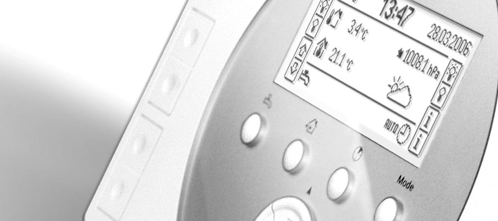
17 Display Backlit display When pressing any of the buttons, the backlit display is switched on for a certain period of time. When pressing the Esc button, the Menu / ok button, the Arrow button or Info button, the backlit display is switched on with no impact on the display itself. The brightness of the backlit display can be adjusted to suit individual needs (refer to page 53). Display The display offers a choice of presentations. The example below shows a menu. Menu symbol: Indicates the menu on which you are Menu title: Indicates the menu on which you are Main menu Heating Switching groups Holidays/special days Time of day/date Access level: The symbol indicates the access level on which you are Scroll bar: Shows the position on the menu list Cursor position: Appears as a black bar with inverse text Extension: Further entries follow 17/80
18 Navigating on the display / information about paths Navigation is made possible with the 2 Arrow buttons, the Menu / ok button and the Esc button (refer to description of the operating elements on page 15). In the description of functions, the location of the function is given in Italics in the form of a path. Example: Main menu > Time of day/date To reach the function from the quiescent picture, press the Menu / ok button first (you reach the main menu). Then, select menu entry Time of day / date with the Arrow buttons and press the Menu / ok button. You are now in function Time of day / date and you can select the parameter to be changed (time of day, date, year) using the Arrow buttons. The parameter setting principle is described on page 21 ff. You return to the quiescent picture by pressing the Esc button several times. Symbols on the display Heating states / cooling mode Comfort mode Precomfort mode Economy mode Protection Apartment timer function active Setpoint limitation Automatic operation Manual operation Summer operation Cooling mode Apartment pump in operation DHW operating states Normal operation Reduced operation DHW Protection DHW heating enabled Automatic operation Manual operation Flashing: Manual forced charging of DHW active Other operating states Fault Flashing: Fault, acknowledgement required Holiday mode Absent Present Special day 18/80
19 Supervision Door open Flashing: Supervised door opened Windows / doors Partly monitored Window open Flashing: Supervised window opened Windows / doors All monitored Temperatures, atmospheric pressure and weather trend Room temperature Outside temperature Weather trend: Sunny Weather trend: Partly cloudy Weather trend: Rainy Atmospheric pressure steady Atmospheric pressure rising Atmospheric pressure strongly rising Atmospheric pressure falling Atmospheric pressure strongly falling The symbols used for the weather trend only indicate the direction in which the weather will change. Assignment of softkeys Switching group on Switching group off Scene Selection of info pages Light on / brighter Light off / darker Blinds opening Blinds closing Device directory Device in order Battery low Device faulty Menu levels Main menu Heating DHW Switching groups Holidays / special days Time of day / date Faults Inputs / outputs Settings Device information Data backup Commissioning Access levels Service level Expert level 19/80
20 Operation Quiescent picture The display shows the quiescent picture as long as no button is pressed. There are 6 formats of quiescent pictures with different degrees of detail available. The settings required for the desired quiescent picture format are described on page 54 ff. Info pages The info pages give an overview of the plant s most important data. Values cannot be readjusted on the info pages. The info pages can be called up with the Info button. Each time the Info button is pressed the next info page appears. The Arrow buttons can be used to scroll forward and backward. To return to the quiescent picture, press the Esc button. When you are on the info level, the respective symbol appears in the corner at top left. At top right, the current info page plus the total number of available info pages are displayed. The following info pages are available: Windows / doors (configurable) Progression of outside temperature (configurable) Progression of atmospheric pressure (configurable) Light state (configurable) Apartment Room (configurable) DHW (configurable) Business card (configurable) Assignment of buttons (always, except when quiescent picture format = 5) Device state Fault status message bus (configurable) The type and number of available info pages depend on your plant (number of rooms, switching groups, etc.). The info pages can also be called up via appropriately assigned softkeys (refer to page 41). 20/80
21 Menu level Press the Menu / ok button to go from the quiescent picture or the info page to the menu level (main menu). Press the Esc button to return to the quiescent picture. Main menu Heating Switching groups Holidays/special days Time of day/date Heading Main menu with the associated symbol appears, followed by the list with the available menus. Setting principle General rules Values are always readjusted in an additional window on the display (edit pop-up). The range of action (cursor) always appears inverse. Readjustments are made in individual steps with the Arrow buttons (up / down). Longer pushes on the buttons speed up the process. Confirm the setting by pressing the Menu / ok button. To cancel the process or to navigate back to the next higher menu level, press the Esc button. The following examples illustrate the different setting choices. Setting a numerical value Comfort With numerical values, the setting range is shown on the left (upper and lower limit). The current setting value appears inverted on the right. 21/80
22 Selecting the selection list Apartment operating mode Auto Comfort Precomfort Selecting options Supervision release Room 1 Room 2 Room 3 For a number of functions, a selection list is available. The selection made is identified by a tick. Only one element of the list can be activated at a time. On the option list, one or several options can be marked with a cross by pressing the Menu / ok button. When pressing the Esc button, a final dialog appears to store the new value (Menu / ok button) or to cancel the setting (Esc button). Creating / editing text Room 1 Use the Arrow buttons to select the individual characters from the character set and the 4 permanently displayed special fields. To confirm the characters or special fields, press the Menu / ok button. The special fields have the following functions: Scrolls the character set upward by 9 characters DEL Deletes the last character in the current text Inserts a blank Scrolls the character set downward by 9 characters When pressing the Esc button, a final dialog appears to store the new text (Menu / ok button) or to cancel the text (Esc button). Setting values and predefined settings When commissioning the system, the activated parameters are loaded in the form of predefined settings. The documentation differentiates between guide values and factory settings. Guide value Setting recommended for most types of plant. Factory setting Setting that should be adapted depending on user- or plant-specific requirements. Use the predefined fields for entering your own settings. 22/80

23 Access levels To select the access level, press the Esc button and the Menu / ok button simultaneously. A pop-up window appears. Press the Arrow buttons to select the required access level and confirm the selection with the Menu / ok button. User level The user level shows the settings most frequently used. Normally, these settings are sufficient for operating the plant. Service level This operating level contains extended settings that are only rarely used. For changing to the service level, a password is required, if such a password has been assigned (refer to page 55). Confirm entry of your password with the Menu / ok button. Expert level The settings of the expert level can only be accessed after entry of a password. For a description of the functions, refer to document Mounting and Commissioning (CE1C2707en). If no button is pressed on the expert level for a certain period of time, the central apartment unit will automatically return to the user level. Keep the passwords of the service and expert level in a safe place where you can easily find them again. Should you lose the service password, you need to contact the expert. Loss of the expert password necessitates a new configuration of the central apartment unit, or a service visit! 23/80
24 Settings The settings described below are to be made only after the Synco 900 system has been commissioned by the expert. The operating lines actually displayed are dependent on the plant s basic configuration. Operating lines that are not required for the configured plant is hidden. If, with a selected parameter, the Info button is pressed, the path and full text of the respective parameter will appear. General Absence If you leave the house for a few hours, you can press the Absence / Supervision button to inform the central apartment unit about your departure. Shortly pressing the Absence / Supervision button opens the presence window which allows you to enter the desired state "Absent" or "Present" via the Arrow buttons or the Absence / Supervision button. If supervision functions are configured, the supervision window opens immediately after the absence window to allow you to enter the desired supervision pattern (see next page). If "Absent" is entered, only the absence symbol appears on the display. Pressing the Absence / Supervision button again opens the absence window, and selecting "Present" deactivates the absence function and the related impact. Your absence has the following impact on the system: During the period of absence, space heating and DHW is controlled in accordance with the operating mode selected for absence A presence simulation program if selected is started Switching groups set for the event Absence on (= going) will operate accordingly (switching / dimming, blinds open / closed, scenes) For additional descriptions, refer to the following pages: Heating mode during absence (page 30). DHW operating mode during absence (page 39). Presence simulation for switching groups (page 46). Triggering a switching group via an event (page 43). 24/80
25 Supervision Briefly pressing the Absence / Supervision button opens the absence window followed immediately by the supervision window. Press the Absence / Supervision button longer than 0.4 s to open the supervision window immediately. This window allows you to select between the following supervision patterns by pressing the Absence / Supervision button or the Arrow buttons: Inactive Partly monitored All monitored The supervision function is inactive. The windows (rooms) and doors selected in the "Partly monitored" option lists are supervised. The windows (rooms) and doors selected in the option lists "All monitored" are supervised. The supervision window appears only if windows or doors are enabled for supervision. See "Release of supervision page 58. When supervised windows and doors are open and when supervision is activated, an associated display appears and a constant signal is sounded. During the set supervision delay, you can close the corresponding doors and windows. After all supervised windows are closed, the constant signal sound turns into a beep whose interval doubles during the last 15 seconds of the set supervision delay. If a supervised window or door is opened during the supervision period, an associated fault message is triggered and other predefined actions are initiated (with an adjustable message delay for doors). Detailed descriptions: Trigger a switching group via an event page 43. Set the supervision delay page 58. Event buzzer and status output page 61. Setting the supervision release (page 58). Setting the message delay (page 60). 25/80
26 Heating Apartment Apartment timer function By pressing the Apartment timer button ( ), you can force the heating system to maintain the Comfort temperature for an adjustable period of time. When pressing the button, the apartment timer window opens. Use the Arrow buttons or the Apartment timer button to set the required period of time for Comfort mode. For each room you can select whether the apartment timer function should be performed (refer to Apartment timer influence on page 34). The apartment timer function can also be selected via the following operating line: Main menu > Heating > Apartment > Apartment operating mode > Apartment timer: If you want to switch off the apartment timer before the adjusted period of time has elapsed, press again the Apartment timer button and set the time to In the case of a manual change of operating mode via the Mode button, the apartment timer function will also be deactivated. Apartment operating mode When pressing the Mode button, an additional window appears (Mode pop-up). Now, you can select the required apartment operating mode (heating) with the Arrow buttons or the Mode button. The apartment operating mode can also be selected via the following operating line: Main menu > Heating > Apartment > Apartment operating mode > Preselection: Auto Comfort Precomfort Economy Protection The room control loops maintain their setpoints in accordance with the respective operating modes. The associated time programs and the holiday / special day program are active. All heating circuits maintain their respective Comfort setpoints. All heating circuits maintain their respective Precomfort setpoints. All heating circuits maintain their respective Economy setpoints. All heating circuits maintain their respective Protection setpoints. The individual room operating modes only act in apartment operating mode Auto. 26/80
27 Apartment operating mode switch You can select the heating mode to which the controller should change when the external operating mode switch closes its contact (e.g. teleswitch for remote control via the telephone). Operating mode changeover via the external switch overrides all other preselected operating modes. Input function Heating mode must be appropriately configured when commissioning the plant. Main menu > Heating > Apartment > Apartment operating mode > Optg mode contact: Factory setting Your setting Protection Comfort Precomfort Economy Protection Summer operation of heating Select the point in time your heating system should switch to summer mode. In summer mode, all room operating modes switch to Protection, the valves travel to the position defined for summer operation and DHW heating switches to the electric immersion heater, if installed. In the case of summer changeover via the external switch, this parameter has no impact (hidden). Input function Summer operation must be appropriately configured when commissioning the plant. Main menu > Heating > Apartment > Summer operation > Preselection: Auto Winter Summer Automatic summer / winter changeover when the summer / winter changeover temperature is attained (refer to page 28) or the date (beginning of summer, end of summer, refer to page 28) is reached. Continuous winter operation Continuous summer operation Factory setting Your setting Auto Auto Winter Summer State of winter operation / summer operation The current operating state of the heating system (summer / winter operation) can be queried: Main menu > Heating > Apartment > Summer operation > State: 27/80
28 Beginning of summer / end of summer From the beginning to the end of summer, the heating system maintains summer operation, provided heating mode has been set to Auto (refer to page 27) and no other changeover criterion (e.g. summer / winter changeover temperature) has become active. Main menu > Heating > Apartment > Summer operation > Summer start: Main menu > Heating > Apartment > Summer operation > Summer end: Beginning of summer End of summer Factory setting (inactive) (inactive) Your setting If the date settings for the beginning and the end of summer coincide, there is no date-dependent changeover to summer operation. Summer / winter changeover temperature The central apartment unit compares the attenuated outside temperature with the adjusted summer / winter changeover temperature and changes the heating mode accordingly, provided no other changeover criterion (e.g. beginning of summer / end of summer) has become active. Main menu > Heating > Apartment > Summer operation > Su/Wi changeover: Factory setting Your setting ---- (inactive) Antilime function To prevent valves and pumps from seizing, the controller periodically drives all valves to their fully open positions and activates all connected pumps in a stepwise fashion at predefined points in time. Main menu > Heating > Apartment > Antilime > Antilime function: Main menu > Heating > Apartment > Antilime > Weekday: Main menu > Heating > Apartment > Antilime > Time of day: Antilime function Weekday Time of day Guide value All-year Monday 10:00 Your setting --- (never) All-year In winter operation In summer operation Monday Tuesday Wednesday Thursday Friday Saturday Sunday : 28/80
29 Rooms 1 12 Room operating modes In addition to the operating mode for the entire apartment, each room has its own operating mode which you can select to suit your needs. Main menu > Heating > Room X > Room operating mode > Preselection: Auto Comfort Precomfort Economy Protection The room is controlled in accordance with the time program and the holiday / special day program. The room is maintained at the Comfort setpoint. The room is maintained at the Precomfort setpoint (for short periods of absence, e.g. when shopping). The room is maintained at the Economy setpoint (e.g. for night setback). The room is maintained at the Protection setpoint (for longer periods of absence, e.g. during holidays). The individual room operating modes are only active in apartment operating mode Auto. State of room operating mode The state of the current room operating mode can be displayed. Main menu > Heating > Room X > Room operating mode > State: Reason for room operating mode If the current room operating mode of a specific room does not satisfy your needs, you can have the reason for the operating mode displayed: Main menu > Heating circuit > Room X > Room operating mode > Cause: The following functions and situations can have an impact on the operating mode of the room: Commissioning Absence / holidays / special day Time switch Room operating mode / apartment operating mode / operating mode switch Room timer / apartment timer Summer Optimum start control / optimum stop control 29/80
30 Room operating mode during absence The room operating mode required during absence (refer to page 24) can be selected for each room. Main menu > Heating > Room X > Room operating mode > Optg mode absence: Room number Room name Factory setting Setting Room number Room name Factory setting Setting = no impact (according to the time program) = Comfort = Precomfort = Economy = Protection Changeover of the respective room operating mode takes place only if the room operating mode during absence is set to a lower level than the room operating mode for normal operation. Room temperature setpoints You can adjust the room temperature setpoint for each individual room (Comfort, Precomfort, Economy, Protection). The central apartment unit maintains the respective setpoint, depending on the selected apartment / room operating mode and / or time program. Main menu > Heating > Room X > Room setpoints >... 30/80
31 Operating mode Comfort Precomfort Economy Protection Guide values 21 C 20 C 15 C 12 C Room 1 Room 2 Room 3 Room 4 Room 5 Room 6 Room 7 Room 8 Room 9 Room 10 Room 11 Room 12 When adjusting the Protection setpoint, give consideration to domestic animals and delicate materials or objects in the house (plants, paintings, etc.). Extremely low room temperatures can cause damage beyond repair! Too high room temperatures lead to higher heating costs. Readjustment of room unit The room temperature setpoint readjustment (+/- 3 K) made on the room unit can be displayed on the central apartment unit for each room: Main menu > Heating > Room X > Room setpoints > Readjustm room unit: The readjustment made on the room unit only acts on the Comfort and the Precomfort setpoint. Setting the time switch of a room In automatic mode, the central apartment unit controls the heating of the individual rooms based on the respective room operating mode and / or the time switch, the holiday or special day program. Selecting the weekday If you wish to set the time switch, first select the weekday for the respective room for which the settings should apply: Main menu > Heating > Room X > Room time switch > Weekday: Room time switch Monday In addition to the weekdays (Mo - Su), a special day is made available. Use the Arrow buttons for navigation. 31/80
32 Displaying switching times At the required weekday, press the Menu / ok button to display the associated switching times and setpoints. Monday From 06:00 Comf Use the Arrow buttons to change between the individual switching points. The factory settings of the switching times of all weekdays are 06:00 (changeover to Comfort mode) and 22:00 (changeover to Economy mode). Copying switching times When you scroll to the end of the switching point list, option Copy to: will appear. Monday Copy to: You can copy the switching times of the respective day to any other weekday (including the special day) or to a number of weekdays (Mo Fr or Mo Su). Setting new switching points For every weekday and the special day, you can set and define up to 6 switching points where the room temperature setpoint should change. Monday - - : To define a new switching point, press the Arrow down button until an empty switching point appears (--:--, after the existing switching points). Now, press the Menu / ok button. Monday Ab 06:00 Comf Use the Navigation buttons to set a value between 00:00 and 23:59. Confirm the setting with the Menu / ok button. Monday From 06:00 Comf Komf Now, adjust the room temperature setpoint (Comfort, Precomfort or Economy) that should apply after this switching time. 32/80
33 Monday From 06:00 Comf To complete the setting, press again the Menu / ok button. The display returns to the menu. Adapting and deleting switching points Monday From 06:00 06:00 Comf To change an existing switching point, select it with the Arrow buttons and then press the Menu / ok button. Use the Arrow buttons to change the value. Monday From :00 : - - Comf To delete a switching point, press the Arrow buttons until - - : - - appears (before 00:00 and after 24:00). Actual value of the room temperature The central apartment unit can display the actual value of the room temperature: Main menu > Heating > Room X > Room state > Act val room temp: Room temperature setpoint The present room temperature setpoint can be queried: Main menu > Heating > Room X > Room state > Current RT setpoint: Setpoint limitation This operating line shows you whether a setpoint limitation is currently acting on the room (triggered by the central communication unit and transmitted via wire-bound bus). Main menu > Heating > Room X > Room state > Setpoint limitation: Valve position The current valve position in each room can be queried: Main menu > Heating > Room X > Room state > Valve position: 33/80
34 Apartment timer influence Define whether or not the apartment timer function of the central apartment unit (refer to page 26) should act on the selected room. Main menu > Heating > Room X > Room settings > Ap timer influence: Room number Room name Factory setting Yes Yes Yes Yes Yes Yes Setting No Yes No Yes No Yes No Yes No Yes No Yes Room number Room name Factory setting Yes Yes Yes Yes Yes Yes Setting No Yes No Yes No Yes No Yes No Yes No Yes Optimum start / stop control Optimum start / stop control brings forward in time changeover of the operating level against the programmed times, which means that consideration is given to the house s thermal dynamics (heating up and cooling down times). This ensures that the required temperature level is reached at exactly the programmed time (e.g. at the end of the holiday period). If that is not the case (too early or too late), a new changeover time is calculated, which is used on the next day. Optimum start / stop control acts between all operating levels, except when switching between Precomfort and Comfort: Comfort mode Precomfort mode Economy mode Protection 34/80
35 The optimization time (forward shift) can be limited to a maximum value, separately for optimum start and optimum stop control (optimum start control 48 hours / optimum stop control hh.mm). When setting the optimization time to ---- or 00.00, the function is deactivated. Main menu > Heating > Room X > Room settings > OptStartCtrl max: Main menu > Heating > Room X > Room settings > OptStopCtrl max: Room number Room name Factory setting Opt start Opt stop Room number Room name Factory setting Opt start Opt stop Room temperature supervision The controller is capable of continuously monitoring the individual room temperatures. If the room temperature exceeds Max temp alarm (0..35 C) or falls below Min temp alarm (0..35 C), an error message is displayed. Setting ---- deactivates temperature supervision of the respective room. Main menu > Heating > Room X > Room settings > Max temp alarm: Main menu > Heating > Room X > Room settings > Min temp alarm: Room number Room name Factory setting Max temp. alarm Min temp. alarm Room number Room name Factory setting Max temp. alarm Min temp. alarm 35/80
36 Window airing function As soon as the central apartment unit detects an open window, the window airing function is activated. In that case, the radiator control valve is limited to its current travel, even if the room temperature drops. The window airing function is aborted as soon as all window contacts in the respective room have closed again, or after the maximum time of the window airing function has elapsed. The required maximum time of the window airing function ( hh.mm) can be defined for each room. On completion of the period of time set, the window airing function is canceled, even if a window contact of the respective room is still open. Main menu > Heating > Room X > Room settings > Window airing: Setting deactivates the window airing function. Room number Room name Factory setting Setting Room number Room name Factory setting Setting Silent mode The SSA955 radiator control actuator can also be operated in silent mode when used in noise-sensitive rooms (e.g. in the sleeping room). Silent mode increases the actuator s power consumption, thus reducing battery life. Main menu > Heating > Room X > Room settings > Silent mode: Room number Room name Factory setting Off Off Off Off Off Off Setting Off On Off On Off On Off On Off On Off On Room number Room name Factory setting Off Off Off Off Off Off Setting Off On Off On Off On Off On Off On Off On 36/80
37 Actuator calibration The radiator control actuators are automatically calibrated when commissioning the plant or when changing batteries. If desired, calibration can also be triggered via the following operating line: Main menu > Heating > Room X > Room settings > Actuator calibration: Actuator calibration is started within 5 minutes after manual triggering. Sensor readjustment In case your room temperature sensor is installed in an unfavorable location, you can match it to the specific room conditions via sensor readjustment ( K). Main menu > Heating > Room X > Room settings > Sensor readjustment: Room number Room name Factory setting Readjustment Room number Room name Factory setting Readjustment 37/80
38 DHW DHW operating mode To change the DHW operating mode, press the DHW button on the central apartment unit. In the DHW pop-up window, you can now select the required DHW heating mode: Auto Normal Reduced Protection DHW is heated up to the Normal setpoint, the Reduced setpoint or the Protection setpoint in accordance with the DHW time program or the holiday program. The DHW temperature is maintained at the Normal setpoint. The DHW temperature is maintained at the Reduced setpoint. The DHW temperature is maintained at the frost Protection setpoint. The selection can also be made via the menu: Main menu > DHW > Operating mode > Preselection: Forced DHW charging With a long push on the central apartment unit s DHW button, one-time forced charging of the DHW storage tank to the Normal setpoint is triggered. During the time forced charging is active, the DHW symbol on the display flashes. Manual forced charging of the DHW storage tank can also be triggered via the following operating line: Main menu > DHW > Operating mode > Forced charging man: State of DHW operating mode The present state of the DHW operating mode can be displayed (Auto, Normal, Reduced, Protection). Main menu > DHW > Operating mode > State: Reason for DHW operating mode If the current DHW operating mode does not satisfy your needs, the reason for the operating mode can be displayed: Main menu > DHW > Operating mode > Cause 38/80
39 Possible reasons for the current operating state: Commissioning Electrical heating Forced charging DHW charging lock Legionella program DHW operating mode (if not Auto ) Special day / holidays / absence DHW time switch Summer operation DHW operating mode during absence The DHW operating mode required during absence can be selected: Main menu > DHW > Operating mode > Optg mode absence: Factory setting --- Your setting --- (no impact, according to time program) Normal Reduced Protection DHW temperature setpoint If the DHW temperature is too high or too low, you can change the setpoint: Main menu > DHW > Setpoints > Normal setpoint: Main menu > DHW > Setpoints > Reduced setp: Normal setpoint Reduced setpoint Factory setting 55 C 40 C Your setting DHW time switch In DHW operating mode Auto, the central apartment unit controls DHW charging in accordance with the DHW time program. Main menu > DHW > Time switch > Weekday X: You can set up to 6 switching points for each weekday plus one special day. You can also define the DHW temperature setpoint (Normal or Reduced) to be used at each switching point. The switching points can be set, deleted or copied to some other weekday. The settings are made analogously to the room time switch settings (refer to page 31). The central apartment unit is supplied with the following factory settings for all weekdays: 05:00 for changeover to the Normal setpoint, 22:00 for changeover to the Reduced setpoint. 39/80
40 Actual value of the DHW temperature The actual value of the DHW temperature can be displayed: Main menu > DHW > DHW state > Act val DHW temp: DHW temperature setpoint The current DHW temperature setpoint can be queried: Main menu > DHW > DHW state > DHW temp setpoint: Operating state of charging pump and electric immersion heater The current operating state of the charging pump and the electric immersion heater can be displayed: Main menu > DHW > DHW state > Charging pump: Main menu > DHW > DHW state > El immersion heater: Plant operation The current operating state of DHW heating (Off / Ready / Charging) can be displayed: Main menu > DHW > DHW state > Plant operation: Reason for DHW plant operation The reason for the current DHW plant operation can be displayed (commissioning / frost / legionella function / time switch): Main menu > DHW > DHW state > Cause: Limitation of charging time This display shows whether limitation of the charging time is currently inactive or active. The maximum permissible charging time was preset when the plant was commissioned. Main menu > DHW > DHW state > Charging time limit: 40/80
41 Changeover to electric immersion heater Select whether in summer operation the DHW should be heated by the electric immersion heater. Yes No When the plant switches to summer operation (refer to page 27), the DHW is heated by the electric immersion heater. This means that heat generation can be switched off in the summer. DHW is heated by the heat source in the summer also. This means that heat generation in the summer remains in operation (emergency operation). If no charging pump is defined, the electric immersion heater is always released (no charging via the heat source). Main menu > DHW > Settings > Change el imm heat: Factory setting Your setting Yes No Yes Supervision of the DHW temperature The controller is capable of continuously monitoring the DHW temperature. If the DHW temperature exceeds Max temp alarm, or falls below Min temp alarm, an error message is displayed. When using setting ----, temperature supervision is deactivated. Main menu > DHW > Settings > Max temp alarm: Main menu > DHW > Settings > Min temp alarm: Max temp alarm Min temp alarm Factory setting ---- (inactive) ---- (inactive) Your setting Switching groups Operating the switching groups Switching groups 1 4 can be operated via the 4 pairs of softkeys on the central apartment unit. The functions of the switching groups (e.g. switching or dimming lights, opening or closing blinds, calling up info pages or scenes) were defined when the plant was commissioned. Switching groups 5 8 have no buttons for direct access. Manual triggering of these switching group functions is only possible via the respective operating lines on the central apartment unit. 41/80
42 The selected function of the pairs of softkeys is displayed in the form of a symbol. Switching group function Switch When pressing the key at the top or bottom, the light is switched on or off. Switching group function Dim Pressing the key at the top or bottom briefly switches the light on or off. Pressing the keys for > 0.4 seconds increases or decreases the intensity of light. Switching group function Blind Pressing the keys briefly adjusts the blinds in steps. Pressing the keys for > 0.4 seconds fully opens or closes the blinds. Switching group function Scene When pressing the keys for < 0.4 seconds, all actuators are driven to the positions set for the respective scene (A or B). The key at the top is used for scene A, the key at the bottom for scene B. When pressing the keys for > 3 seconds, the current positions of the actuators are stored under the respective scene (A or B). Storage is confirmed by a short acoustic signal. Switching group function Info When pressing the key at the top or bottom, the info page assigned to the key is displayed. The switching groups can also be triggered via the operating lines. You operate a switching group configured for Switch, Dim or Blind under: Main menu > Switching groups > Switching group X > Trigger: You operate a switching group defined as Scene under: Main menu > Switching groups > Switching group X > Scene A or B > Trigger scene: The text displays for scenes A and B can be adjusted to suit your needs (refer to page 43). Scenes When commissioning the plant, the softkeys of the central apartment unit (switching groups 1 4) can be programmed for triggering scenes (scene symbol appears on the display of the key assignment). Scenes can be used to store certain states of all actuators involved and to retrieve them again, if desired. One example would be the differently dimmed lights and the blind positions that you would consider adequate for a certain event / at certain times. 42/80
43 Creating scenes For the switching groups, a scene A and scene B can be created. Enter the required name of the scene at the central apartment unit: Main menu > Switching groups > Switching group X > Scene A or B > Scene A or B: Then, use local actuator control to drive all actuators to the required position. After that, store the scene by pressing the respective softkey for at least 3 seconds. Storage is confirmed by the central apartment unit in the form of a short acoustic signal. You trigger the stored scenes by a short push on the respective softkey. The scenes can also be stored and retrieved via operating parameters: Main menu > Switching groups > Switching groups X > Scene A or B > Trigger scene: Triggering switching groups via an event In addition to manual triggering, the function of a switching group can be automatically triggered via one or several events. Select the event (or the events) that triggers a switching group configured for Switch or Dim: Main menu > Switching groups > Switching group X > Events on cmd: Main menu > Switching groups > Switching group X > Events off cmd: Select the event (or the events) that triggers a switching group configured for Blind: Main menu > Switching groups > Switching group X > Events up cmd: Main menu > Switching groups > Switching group X > Events down cmd: Select the event (or the events) that triggers a switching group configured for Scene: Main menu > Switching groups > Switching group X > Scene A or B > Events scene: 43/80
44 The following events are available for triggering switching group functions: No. Designation Meaning 1 Absence ON Execution of command when changing from "Absence OFF to "Absence ON (= going). 2 Absence OFF Execution of command when changing from "Absence ON to "Absence OFF (= coming). 3 Twilight switch dark 4 Twilight switch bright 5 Twilight switch dark + absent 6 Twilight switch bright + absent Execution of command when the twilight switch changes from BRIGHT to DARK. Execution of command when the twilight switch changes from DARK to BRIGHT. Execution of command when the twilight switch changes from BRIGHT to DARK and when "Absence ON, or when changing from "Absence OFF to "Absence ON and twilight switch signals DARK. Execution of command when the twilight switch changes from DARK to BRIGHT and when "Absence ON. 7 Smoke Execution of command when the smoke detector detects smoke. 8 Window / door supervision Execution of command when window / door supervision is triggered (see page 58). 9 Fault input 1 Execution of command when an event is detected at fault input 1 (contact not in the normal position). 10 Fault input 2 Execution of command when an event is detected at fault input 2 (contact not in the normal position). 11 Fault input 3 Execution of command when an event is detected at fault input 3 (contact not in the normal position). 12 Fault input 4 Execution of command when an event is detected at fault input 4 (contact not in the normal position). 44/80
45 Time switch for switching groups Control of the individual switching groups takes place either manually or according to the associated time switch. Available for each switching group are 7 weekdays and one special day, each with up to 8 switching points. The time switch settings are made analogously to those of the room time switch (refer to page 31). Main menu > Switching groups > Switching group X > Time switch > Time switch release Define for each switching group if the time switch is to be enabled always or only for absence. Main menu > Switching groups > Switching group X > Time switch release: Always The time switch of the switching group is always considered. If absent The time switch of the switching group is considered only for absence. Switching group Factory setting Always Always Always Always Your setting Always If absent Always If absent Always If absent Always If absent Switching group Factory setting Always Always Always Always Your setting Always If absent Always If absent Always If absent Always If absent Abs Time switch The setting "If absent "allows you to prevent from being locked out by automatically closing blinds when you are sitting on the balcony or in the yard for example. 45/80
46 Simulation of presence Time switch for simulation of presence During absence (absence function activated), you can control the switching groups via a special time switch (T swi) in a way that presence is simulated. When presence simulation is activated, the switching groups are switched on and off randomly in dependence of the selected function (Random / Continuously On). This function is only available with switching groups that afford Switch or Dim. The time program defines the periods of time during which presence simulation is active. Available are 7 weekdays and one special day, each with up to 6 switching points. Main menu > Switching groups > Time swi presence simulation > The central apartment unit is supplied with the following factory-set switching times for all weekdays: 06:00 (start of presence simulation), 08:00 (end of presence simulation), and 17:00 (start of presence simulation), 23:00 (end of presence simulation). Using the special day, define whether and for what periods of time during holidays and special days you want presence simulation. The periods of time defined apply jointly to all switching groups. Activating simulation of presence The effect of presence simulation (release and function) can be set individually for each switching group: Release Release allows you to control switching groups in dependence of a time switch or as a combination of time switch and twilight switch. Main menu > Switching groups > Switching group X > Presence simulation > Release: The following settings are available: --- Inactive no presence simulation for this switching group With time switch (T swi) Presence simulation enabled according to Time swi presence simulation With time swi + twilight Presence simulation enabled swi (T swi + twil) according to Time swi presence simulation and twilight switch signals DARK 46/80
47 Switching group Factory setting Your setting --- T swi T swi+ twil --- T swi T swi+ twil --- T swi T swi+ twil --- T swi T swi+ twil Switching group Factory setting Your setting --- T swi T swi+ twil --- T swi T swi+ twil --- T swi T swi+ twil --- T swi T swi+ twil T swi Twil Time switch Twilight switch Example of release according to the time switch: A On Off B2707Z01 B On Off C On Off A B C D E F t A B C t Time program presence simulation (On, Off) Absence (On, Off) Release of simulation (On, Off) Time Example of release according to the time switch and the twilight switch: A On Off B2707Z02 B On Off C DA BR D On Off A B C D E F G t A B C D t Time program presence simulation (On, Off) Absence (On, Off) Twilight (DA = DARK, BR = BRIGHT) Release of simulation (On, Off) Time 47/80
48 Function Function allows you to control switching groups by at random or constant switch-on of a switching group. The setting is effective only if the presence simulation of the corresponding switching group as described above is enabled. Main menu > Switching groups > Switching group X > Presence simulation > Function The following settings are available: Random Continuously On (Contin on) The switching group actors are switched on or off within the set period at random intervals of 3 to 30 minutes. The first switch-on of each switching group also is at random. The switching points of the individual switching groups differ. The switching group is switched on constantly. This allows you to ensure that at least one light is on during the presence simulation. Switching group Factory setting Random Random Random Random Your setting Random Contin on Random Contin on Random Contin on Random Contin on Switching group Factory setting Random Random Random Random Your setting Random Contin on Random Contin on Random Contin on Random Contin on The settings Release and Function become effective as soon as the central apartment unit is set to "Absent" via Absence / Supervision button : On Off On Off On Off On Off B2707Z04a A On Off Min Min B On Off C On Off t A B C t Simulation release (On, Off) Light (On, Off) with function "Random" Light (On, Off) with Function "Contin on" Time The presence simulation is ended as soon as the central apartment unit is set to "Present". 48/80
49 Holidays / special days Calendar Setting holidays / special days If you are absent for one or several days, or if your occupancy pattern is different on certain days (e.g. on public holidays), you can define a holiday period or a special day. For each of the 16 entries made, start, end and the reason (holidays or special day) can be entered. In that case, you can also define whether the event is repeated every year (* with entry of year), or whether it should be deleted again after the event took place (entry with indication of year). Every entry can be deleted. Main menu > Holidays/special days > Calendar > Entry X: During holiday periods, the selected room operating mode and the holiday DHW operating mode apply. For a description of the room operating mode settings required and the DHW operating mode during holidays, refer to page 50. During special days, the special day time program of the respective rooms and of DHW is used. The special days with room and DHW time switches can be used for programming public holidays that fall on working days (Mo Fr), for example. For such days, you probably wish to use a temperature profile similar to Sundays. With the special day of the switching group time switches, it is possible to determine which functions should be triggered during special days and holidays. Main menu > Heating > Room X > Room time switch > Special day: Main menu > DHW >Time switch > Special day: Main menu > Switching groups > Switching group X > Time switch > Special day: If the supervisory functions, presence simulation, etc., should be available during the holiday period / special days, the absence function must also be activated (refer to the following section). 49/80
50 Holidays and absence simultaneously The holiday program only acts on the space heating and the DHW operating mode. Also press the Absence button if, in addition to the holiday program, you want to take advantage of the absence functions (presence simulation, supervisory function, etc.). When the holiday and absence functions are simultaneously active, the central apartment unit controls space heating and DHW heating in accordance with the holiday operating mode. At the end of the holiday period / special day, room and DHW operating mode will switch from Holidays to Absence. This means that on return from holidays, the absence function must be deactivated again by pressing the Absence button. During absence, ensure that the temperature level will not be too low ( Precomfort or no impact ) to make certain that on completion of the absence period the Comfort setpoint is quickly reached again. Slow heating systems (e.g. underfloor heating systems) require more time until the desired room temperature is reached. Holiday operating mode Room operating mode during holidays Select the required room operating mode for the apartment during the holiday period: Main menu > Holidays/special days > Rm optg mode holid.: Guide value Economy Your setting Economy Protection DHW operating mode during holidays Select the required DHW operating mode for the holiday period or the special day: Main menu > Holidays/special days > DHW optg mode holid: Guide value Your setting Protection --- (no impact) Normal Reduced, Protection 50/80
51 Time settings Date / time of day You can make the settings for the date and the time of day by using the following paths: Main menu > Time of day/date > Time of day: Main menu > Time of day/date > Date: Main menu > Time of day/date > Year: Faults Error / fault status messages The central apartment unit stores up to 10 current fault status messages according to priority. They can be retrieved at any time. The lowest fault status message number represents the fault with the highest priority. If priorities are equal, the faults are listed in chronological order. Both the central apartment unit s internal faults and the faults of the other devices contained in the system are taken into consideration. Each device only transmits its most severe fault to the central apartment unit. As soon as that fault has been rectified, the next fault is transmitted. The faults acquired are written to the Current list of faults. Main menu > Faults > Faults current > Fault X: With each fault status message, a fault number and fault text are displayed. The faults can be linked to internal or external fault relays. The relevant relay is energized when the fault occurs (refer to page 57). Fault status messages bus The fault that occurred last on the wire-bound bus is saved with the fault number, fault text and the associated device address. These fault status messages are only visible if they were enabled at the time of configuration: Main menu > Faults > Fault status message bus: 51/80
52 Acknowledging faults The current fault status messages can be jointly acknowledged. Main menu > Faults > Acknowledge faults: A fault that has not yet been acknowledged appears on the display with a flashing fault symbol. As soon as the fault is acknowledged, the fault symbol will stop flashing. Inputs / outputs Displaying input signals The current input signals can be displayed via the following operating line: Main menu > Inputs / Outputs > Inputs > The following values if available are displayed: Actual value of the outside temperature DHW temperature sensor Heating mode Summer operation H/C changeover Absence Twilight Fault input X (per fault input 1-4) Displaying output states The states of the outputs can be displayed via the following operating line: Main menu > Inputs / Outputs > Outputs > The following values if available are displayed: DHW pump / valve Electric immersion heater Switching group X (relay per switching group 1-8) Fault output X (per fault output 1 and 2) Heat demand relay Heat demand DC V Apartment pump Summer operation Status output Window / door state 52/80
53 Settings Device Language The unit is supplied with English preselected as the operator s language. You can select the language you prefer: Main menu > Settings > Device > Language: Then, the path can be reached in the language selected by you. Elevation above sea level To ensure display of accurate weather forecasts in the quiescent picture, the absolute atmospheric pressure acquired by the meteo sensor is converted to pressure at sea level. For this reason, the plant s location above sea level must be known. Enter the plant s elevation above sea level on the following operating line: Main menu > Settings > Device > El above sea level: Factory setting Your setting 0 m above sea level Time-of-day format The format for display of the time of day can be selected (24 h or 12 h am / pm): Main menu > Settings > Device > Time format: Factory setting Your setting 24 h 12 h 24 h Backlit display / display contrast Adjust the brightness of the backlit display and the display contrast to suit your needs: Main menu > Settings > Device > Backlit display: Main menu > Settings > Device > Display contrast: Backlit display Display contrast Factory setting 100 % 50 % Your setting 53/80
54 Quiescent picture Display format You can select the display format required for the quiescent picture. Main menu > Settings > Quiescent picture > Display format: The following display formats are available: Display format 0 Display format 1 Tuesday Tuesday 01: C 1013 hpa 5 C Display format 2 Display format 3 Tuesday 01: Tuesday 01: C 1013 hpa 20 C 1013 hpa 5 C 5 C Display format 4 Display format 5 Tuesday 01: Tuesday 01: C 5 C 1013 hpa Living Living Eating Outside temp. Atm. pressure Factory setting Display format 4 Your setting Temperature display Select the room (rooms 1 12) whose temperature should be displayed in the quiescent picture. Main menu > Settings > Temp display: Factory setting Room 1 Your setting 54/80
55 Passwords Password for the service level The unit comes supplied with no password protection on the service level. Password protection is available as an option (1 9999). Use the following path to enter your password and confirm it by pressing the Menu / ok button: Main menu > Settings > Passwords > Service: Factory setting --- Your setting For more information about the various access levels, refer to page 23. Info page selection Direct selection of info pages When commissioning the plant, the softkeys of the central apartment unit (switching groups 1 4) can be programmed for the display of info pages (the info symbol appears on the display of the key assignments). Note that the number of info pages and thus the info page number of a certain component / function is dependent on the configuration of the central apartment unit. You can see the current numbering of the info pages when scrolling with the Info button. For numbering the softkeys (switching groups 1 4), refer to the following illustration: 1A, 1B Softkeys of switching group 1 2A, 2B Softkeys of switching group 2 3A, 3B Softkeys of switching group 3 4A, 4B Softkeys of switching group 4 With the softkeys defined as info pages, you can select the info pages that should be displayed when pressing the keys. 55/80
56 Main menu > Settings > Info page selection > Info page button 1A: Main menu > Settings > Info page selection > Info page button 1B: Main menu > Settings > Info page selection > Info page button 2A: Main menu > Settings > Info page selection > Info page button 2B: Main menu > Settings > Info page selection > Info page button 3A: Main menu > Settings > Info page selection > Info page button 3B: Main menu > Settings > Info page selection > Info page button 4A: Main menu > Settings > Info page selection > Info page button 4B: Faults Fault inputs 1 4 Faults of external plant components can be communicated to the central apartment unit by closing a contact. There are 4 fault inputs available. The fault inputs must have been activated when commissioning the plant, and the required input must be connected to the central apartment unit so that the settings described here can be made. For the relevant descriptions, refer to document Mounting and Commissioning (CE1C2707en). For each fault input, following can be selected or set: Fault text (text that should be displayed at the respective fault input when the fault occurs) Fault priority (urgent or Not urgent) Fault release (always or only during absence) Fault status message delay (time span m.s., until a pending fault generates a fault status message) Normal position: It can be selected here whether an open or closed contact should be used to indicate a faulty condition. Normally open means that an open contact is considered to indicate normal operation Main menu > Settings > Faults > Fault input X > Fault text: Main menu > Settings > Faults > Fault input X > Fault priority: Main menu > Settings > Faults > Fault input X > Fault release: Main menu > Settings > Faults > Fault input X > Fault stat mess dly: Main menu > Settings > Faults > Fault input X > Normal position: 56/80
57 Fault input FS fault text Fault inp 1 Fault inp 2 Fault inp 3 Fault inp 4 Fault text FS fault priority Not urgent Not urgent Not urgent Not urgent Fault priority Urgent N. urg. Urgent N. urg. Urgent N. urg. Urgent N. urg. FS fault release Always Always Always Always Fault release Always DA Always DA Always DA Always DA FS fault stat mess dly Fault status message delay FS normal position Open Open Open Open Normal position FS Factory setting N. urg. Not urgent DA During absence Fault outputs 1 and 2 Open Closed Open Closed Open Closed Open Closed To forward fault status messages or to indicate them on the control panel with a lamp, for instance, 2 fault outputs can be configured. The fault outputs must have been activated when commissioning the plant, and the required relay output must be connected to the central apartment unit so that the settings described here can be made. For the relevant descriptions, refer to document Mounting and Commissioning (CE1C2707en). Main menu > Settings > Faults > Fault output X > Fault priority: Main menu > Settings > Faults > Fault output X > Fault source: For each fault output, the following settings can be made: Fault priority: The priority (urgent or Not urgent) with which the relay should be energized can be selected here Fault source: Defines whether the relay should respond only in the case of internal faults or only in the case of external faults (faults transmitted via bus) Maximum one bus fault status message can be handled. If both relays are set as bus relays with different priorities, only one of them can be energized at a time, even if several faults with different priorities are pending on the bus! It is therefore recommended to configure only one relay as a bus fault relay. Fault relay 1 2 FS fault priority All All Fault priority Urgent Not urgent All Urgent Not urgent All FS fault source Internal Bus FS Fault source Factory setting Internal Bus Internal Bus The fault relay remains energized until the fault is acknowledged. 57/80
58 Supervision of doors and windows Supervision delay You can set a supervision delay to avoid generating a message upon supervision activation and simultaneously open window / door. If supervised windows are open when supervision is activated, a constant beep is sounded. The Info page Windows / Doors provides information on which rooms contain open windows or doors. Any open windows and doors can now be closed. After you close the supervised window, the constant signal becomes a beep that doubles in the last 15 seconds of supervision delay. The remaining supervision delay time is also displayed on the central apartment unit. You can set the desired delay time ( m/s) via the following command sequence: Main menu > Settings > Supervision > Supervision delay: The set delay time applies to all windows and doors. Factory setting Your setting m.s You can set the volume of the signal / beep as desired (0..100%). While you adjust the volume, a constant beep is sounded at the selected volume. Main menu > Settings > Supervision > Volume supervis dly: Factory setting 15 % Your setting Setting 0 % deactivates the signal sound / beep during supervision delay. Release of supervision Indicate in the central apartment unit the doors and windows that are to be "partly monitored" or "all monitored". These two functions provide for two different types of supervision, e.g. for short absences when you want to keep open some windows for ventilation and thus exclude them from supervision. And for longer absences (e.g. vacation) when you want to supervise all windows and doors. Windows The option list contains all rooms. Select the rooms with windows to be supervised. If a supervised window is opened, the message "Window open" appears. In addition, the buzzer, the status output, and a switching group function can be activated. 58/80
59 The "Window open" fault message remains active until supervision is changed, even after all supervised windows are closed. Main menu > Settings > Supervision > Windows > Rel "Partly monit": Room number Room name Factory setting No No No No No No Setting No Yes No Yes No Yes No Yes No Yes No Yes Room number Room name Factory setting No No No No No No Setting No Yes No Yes No Yes No Yes No Yes No Yes Main menu > Settings > Supervision > Windows > Rel. "All monit ": Room number Room name Factory setting No No No No No No Setting No Yes No Yes No Yes No Yes No Yes No Yes Room number Room name Factory setting No No No No No No Setting Doors No Yes No Yes No Yes No Yes No Yes No Yes You can supervise up to two doors. The doors you want to supervise can be selected in the option list. Main menu > Settings > Supervision > Doors > Rel "Partly monit": Door number 1 2 Door name Factory setting No No Your setting No Yes No Yes Main menu > Settings > Supervision > Doors > Rel "All monit": Door number 1 2 Door name Factory setting No No Your setting No Yes No Yes 59/80
60 Message delay IF a supervised door is opened, the fault message "Door open" appears only after expiration of a set message delay time. In addition, the buzzer, status output and a switching group function can be activated. The "Door open" fault message remains active until supervision is changed, even after all supervised doors are closed. You can set the duration of the message delay time ( m/s): Main menu > Settings > Supervision > Doors > Message delay: Factory setting Your setting m.s You must deactivate supervision before the message delay time has expired to avoid the fault message "Door open" and the alarm sound. To do this, set the message delay time to ensure that you have sufficient time to go to the central apartment unit and deactivate supervision when returning home. See page 60. When a supervised door is opened, a beep is sounded whose frequency doubles in the last 15 seconds of the message delay time. You can set the volume of the beep (0..100%) or deactivate it by entering setting 0%. When you set the volume, a permanent beep is sounded at the corresponding volume. Main menu > Settings > Supervision > Doors > Volume mess delay Factory setting 15 % Your setting If event "Window / door supervision" is active at the buzzer (see parameter below), the actual alarm is sounded 60/80
61 Event buzzer and status output Decide with which event the buzzer and / or the status output is to be activated (smoke, window / door supervision or fault input 1 4). It is possible to select several simultaneous events: Main menu > Settings > Supervision > Signaling > Events buzzer: Main menu > Settings > Supervision > Signaling > Events status outp: Events buzzer Events status output Factory setting Smoke Window / door supervision Smoke Window / door supervision Setting Smoke Window / door supervision Fault input 1 Fault input 2 Fault input 3 Fault input 4 Smoke Window / door supervision Fault input 1 Fault input 2 Fault input 3 Fault input 4 Signal duration Signal duration for the buzzer and the status output can be selected (1 60 minutes, --- unlimited). When the set signal time has elapsed, the buzzer stops and the status output s relay drops out again, even if the triggering event is still pending. Main menu > Settings > Supervision > Signalization > Signal duration: Factory setting Your setting 3 minutes As soon as one of the buttons on the central apartment unit is pressed, both buzzer and status output will immediately be deactivated again independent of the set signal duration. 61/80
62 Texts Plant name Assign the plant or the apartment a self-explanatory name, e.g. Main street 22 : Main menu > Settings > Text > Plant name: Room names 1 12 Assign the rooms self-explanatory names, e.g. Living, Eating, Parents, Children, Bathroom, etc.: Main menu > Settings > Text > Rooms > Room X: Switching group names 1 8 Assign the switching groups self-explanatory names, e.g. Living, Eating, Parents, Children, Bathroom, etc. Main menu > Settings > Text > Switching groups > Switching group X: Door names 1-2 Assign a meaningful name to the doors, e.g. entry door, garage door, etc. Main menu > Settings > Texts > Doors > Door X: Lamp names 1 4 Assign the lamps self-explanatory names, e.g. Living, Eating, etc.: Main menu > Settings > Text > Light state > Lamp X: Info lines The central apartment unit provides information for readout: Main menu > Device information > Plant name: Main menu > Device information > File name: Main menu > Device information > Device type: Main menu > Device information > Software version: Main menu > Device information > Hardware version: 62/80

63 Room unit QAW910 Operation All operating elements are arranged on the front of the unit. The function button is located in the battery compartment. The room unit communicates via radio signals and has no connection terminals. The settings made on the room unit only have an impact on the room to which the room unit is assigned. They have no influence on any other rooms. The settings made on the room unit are automatically synchronized with the settings of the central apartment unit. Room operating modes By pressing the Mode button, you can select the required room operating mode. The display shows the hourglass symbol which disappears again as soon as the central apartment unit and the room unit have adopted the new settings. AUTO MAN MAN MAN MAN The room is controlled in accordance with the time program and the special day program. The room is maintained at the Comfort setpoint. The room is maintained at the Precomfort setpoint. The room is maintained at the Economy setpoint. The room is maintained at the Protection setpoint. Overriding by the central apartment unit to maintain the Comfort setpoint. Overriding by the central apartment unit to maintain the Precomfort setpoint. Overriding by the central apartment unit to maintain the Economy setpoint. Overriding by the central apartment unit to maintain the Protection setpoint. 63/80 Building Technologies Room unit QAW
64 The time program and the special day program are set on the central apartment unit. In the case of overriding by the central apartment unit, the display shows the symbol of the central apartment unit and the symbol of the active operating level. Room timer function Using the Room timer button ( ), you can force the heating system to maintain the Comfort temperature for an adjustable period of time. When pressing the button, the room timer symbol, the symbol of the Comfort setpoint and the duration of the selected Comfort mode (00:00) will appear on the display. With every push on the Room timer button, the duration of Comfort mode is extended by 30 minutes. Pressing the button speeds up the setting. If no button is pressed for 4 seconds, the setting is adopted and Comfort mode is displayed. The display shows the hourglass symbol which disappears again as soon as the central apartment unit has adopted the settings made on the room unit. When the room timer function is active and the Room timer button is pressed, the timer s remaining time is displayed. It can be set to 30 minutes by pressing again the Room timer button and each additional push of the button extends the time by another 30 minutes. An active room timer function can be aborted by setting the extension time to 00:00, or by pressing the Mode button. For the room timer function to be activated, the apartment operating mode must be set to Auto. In addition, no absence or holiday function for the apartment may be active. 64/80 Building Technologies Room unit QAW

65 Readjustment of the room temperature setpoint Room temperature setpoint readjustments by a maximum of +/- 3 K can be made with the setting knob. When turning the knob one step, the display shows the current room temperature setpoint readjustment. Each step represents another readjustment of 0.5 K. The readjustments made on the individual room units can be displayed on the central apartment unit (refer to page 31). The room temperature setpoint readjustment is displayed with a readjustment bar. When controlling to the Precomfort or Comfort setpoint, the readjustment bar continues to be displayed also after leaving the room temperature setpoint readjustment. The room temperature setpoint readjustment made only acts on the Comfort or the Precomfort setpoint. Display Full display When commissioning the unit, the full display appears for 2 seconds, enabling you to check it. 65/80 Building Technologies Room unit QAW
Synco 900 Operating Instructions. Edition 1.0 Controller series 1 CE1B2707en Building Technologies HVAC Products
 Synco 900 Operating Instructions Edition 1.0 Controller series 1 CE1B2707en 19.07.2006 Building Technologies HVAC Products We congratulate you on the selection of the Siemens Synco 900 system and thank
Synco living Operating Instructions. Edition 3.0 Controller series C CE1B2707en Building Technologies
 s Synco living Operating Instructions Edition 3.0 Controller series C CE1B2707en 23.08.2008 Building Technologies Congratulations on choosing the Siemens Synco living system and thank you for purchasing
Synco living Operating instructions. Building Technologies
 s Synco living Operating instructions Edition 1.0 QAX9x3 Series A CE1B2740en 13.12.2010 Building Technologies Congratulations on choosing the Siemens Synco living system and thank you for purchasing the
Central apartment unit
 s 2 707 Synco living Central apartment unit QAX910 Series C Management of room control for one apartment including precontrol of heating for 2 room groups Management of ventilation plant Management of
Central apartment unit with QAX913 consumption data acquisition
 s 2 740 Synco living Central apartment unit with QAX913 consumption data acquisition Series A Heating and cooling control management for an apartment including precontrol for 2 room groups Ventilation
Synco living. Train the Tainer. Functions & Operation Safety & Security. Spring 2008 Page 1/32 Train the Trainer - Spring 2008
 Synco living Train the Tainer Functions & Operation Safety & Security Spring 2008 Page 1/32 Train the Trainer - Spring 2008 Settings Absence & supervision Window / door supervision Signaling (buzzer /
RVP360 and RVP361 Heating controllers for 2 heating circuits and d.h.w. Basic Documentation
 RVP360 and RVP361 Heating controllers for 2 heating circuits and d.h.w. Basic Documentation Edition 1.0 Controller series A CE1P2546en 15.03.2011 Building Technologies Siemens Switzerland Ltd Industry
Heating and D.h.w. Controller RVL482 Basic Documentation
 Heating and D.h.w. Controller RVL482 Basic Documentation Edition: 1.0 Controller series: A CE1P2542en 20.05.2008 Building Technologies Siemens Switzerland Ltd Building Technologies Group International
Synco living. Train the Trainer. Commissioning Safety & Security. Spring 2008 Page 1/21 Train the Trainer - Spring 2008
 Synco living Train the Trainer Commissioning Safety & Security Spring 2008 Page 1/21 Train the Trainer - Spring 2008 Introduction Procedure to be followed when commissioning safety and security: 1. Make
Synco-GAMMA Application Guide. School building class room. Answers for infrastructure.
 Synco- Application Guide School building class room Answers for infrastructure. More efficiency in schools with Synco and building control Requirements Single source Objective of this document School
Saving energy with Synco
 Saving energy with Synco Tips and hints for installers Answers for infrastructure. Content Massive savings made easy... 4 Synco controller: Our response to energy efficiency... 5 Operation... 6 Operating
RVP340 Heating controller for 1 heating circuit RVP350 and RVP351 Heating controllers for 1 heating circuit and d.h.w. Basic Documentation
 RVP340 Heating controller for 1 heating circuit RVP350 and RVP351 Heating controllers for 1 heating circuit and d.h.w. Basic Documentation Edition 2.0 Controller series A CE1P2545en 2018-07-27 Building
RVS43.. RVS63.. AVS75.. AVS37.. QAA75.. QAA78.. QAA55.. Albatros2 Boiler controllers User manual. Building Technologies HVAC Products
 Albatros2 Boiler controllers User manual Edition 2.0 Controller series B CE1U2354en 11. May 2007 RVS43.. RVS63.. AVS75.. AVS37.. QAA75.. QAA78.. QAA55.. Building Technologies HVAC Products 2/156 HVAC Products
USER MANUAL S203. Controller for three circuits. - control for 2 heating circuits - 1 domestic hot water control. Saving energy, creating comfort
 USER MANUAL S203 Controller for three circuits - control for 2 heating circuits - 1 domestic hot water control Saving energy, creating comfort This user manual consists of two parts. Issues that are intended
PRELIMINARY EDITION
 3 131 PRELIMINARY EDITION 14.01.2003 Synco 700 Heating Controllers Heating controller for medium-size and large buildings. The is used as a heating circuit or primary controller. The controller is supplied
Operating Instructions Heating Controllers RVL479, RVL480, RVL481, RVL482
 Operating Instructions Heating Controllers RVL479, RVL480, RVL481, RVL482 Content Overview, display, and symbols... 4 Info button... 7 Operating modes... 8 Switching the heating ON... 9 D.h.w. heating...
Albatros2 Boiler Controllers User Manual RVS13.. RVS53.. Siemens Schweiz AG HVAC Products. Edition 1.0 Controller series A CE1P2383en
 Albatros2 Boiler Controllers User Manual Edition 1.0 Controller series A CE1P2383en 01.05.12005 RVS13.. RVS53.. Siemens Schweiz AG HVAC Products 2/89 HVAC Products 6. June 2005 Contents 1 Summary...7 1.1
RVL471 Heating and Domestic Hot Water Controller Basic Documentation
 RVL471 Heating and Domestic Hot Water Controller Basic Documentation Edition: 2.2 Controller series: C CE1P2524E 23.10.2002 Siemens Building Technologies HVAC Products 2/118 HVAC Products 23.10.2002 Contents
RVL481. Heating Controller. including d.h.w. heating
 2 541 Heating Controller including d.h.w. heating RVL481 Multifunctional and communicating heating controller for use in residential and non-residential buildings. Suited for heating circuit control with
RVL472. Heating Controller. Building Technologies HVAC Products. Series C. including d.h.w. heating
 2 526 Heating Controller including dhw heating Series C RVL472 Multifunctional heating controller for use in residential and non-residential buildings Suited for: Heating zone control with or without room
RVS46.. AVS75.. AVS37.. QAA75.. QAA78.. QAA55.. Albatros 2 Zone controller User Manual. Building Technologies HVAC Products
 Albatros 2 Zone controller User Manual RVS46.. AVS75.. AVS37.. QAA75.. QAA78.. QAA55.. Edition 3.0 @@@@ CE1U2353en 02.06.2009 Building Technologies HVAC Products 2/135 HVAC Products 02.06.2009 Contents
RVL479. Heating Controller. for use with a partner unit
 2 543 Heating Controller for use with a partner unit RVL479 Communicating heating controller for use in residential and non-residential buildings. For exclusive use on the bus together with heating controllers
RVL471. Heating controller. G2524en. Installation Instructions. 1 Installation. 2 Commissioning
 G2524en Heating controller Installation Instructions RVL471 1 Installation 1.1 Place of installation In a dry room, e.g. the boiler room Mounting choices: In a control panel (on the inner wall or on a
HMC300. Control unit. Operating Instructions. EMS plus (2014/10) O
 O") HMC300 Control unit EMS plus 6 720 808 471-00.1O Operating Instructions 6 720 813 192 (2014/10) Contents Contents Key to symbols and safety instructions................3 1.1 Key to symbols...........................
HMC300 Control unit EMS plus 6 720 808 471-00.1O Operating Instructions 6 720 813 192 (2014/10) Contents Contents Key to symbols and safety instructions................3 1.1 Key to symbols...........................
Heating Controller SDC. District Heating Controller DHC 43 OPERATING INSTRUCTIONS
 Heating Controller SDC District Heating Controller DHC 43 OPERATING INSTRUCTIONS Copyright 2002 Honeywell Inc. EN2H-0220 GE51 R0802 SDC / DHC 43 Operating Instructions EN2H-0220 GE51 R0802 Contents SDC
REA22 Room Temperature Controller
 REA22 Room Temperature Controller Basic Documentation Issue: 2.0 Controller series: A CE1P2276E 31.03.1999 Siemens Building Technologies Landis & Staefa Division Siemens Building Technologies Ltd. Landis
Room Unit for Boiler Control QAA User manual. Building Technologies. With OpenTherm Interface
 s Room Unit for Boiler Control With OpenTherm Interface User manual QAA73.210 Edition 1.0 Device series A CE1U2283en 16.08.2010 Building Technologies Siemens Switzerland Ltd Industry Sector Building Technologies
RVL480. Heating Controller
 2 540 Heating Controller RVL480 Multifunctional and communicating heating controller for use in residential and non-residential buildings. Suited for heating circuit control, boiler temperature control
Use of the application program. Functional description. instabus EIB Application program description. October CO Touch-Manager wave
 Use of the application program Product family: Product type: Manufacturer: Display Display units Siemens Name: Touch-Manager wave UP 582 silver, with monochrome display Order no.: 5WG3 582-2AB71 Name:
Modulating clock thermostat
 EN Digital timer thermosatat Modulating clock thermostat Installation and Service Manual 123189-AB Contents 1 Preface...4 1.1 General...4 2 Location of the installation...5 2.1 Position of the regulator...5
Operating Instructions
 Operating Instructions Heating Controller SIGMAGYR RVL47 Overview... 2, 3 Symbols used... 4 Info button... 5 Operating modes... 6 Switching the heating on... 7 Room temperature is not correct... 8 Departing
RVP310. Heating Controller. Building Technologies HVAC Products
 2 475 Heating Controller RVP310 Multifunctional heating controller for use in residential and non-residential buildings; suitable for weather-dependent flow temperature control of heating zones with or
Climapro 2. User manual. wireless room thermostat without receiver. To be left with the user.
 Climapro 2 User manual To be left with the user wireless room thermostat without receiver www.glow-worm.co.uk table of contents READ CAREFULLY BEFORE USING 1 Introducing your Climapro 2... 3 1.1 Description...
District heating controller
 2 515 District heating controller for 2 heating circuits and d.h.w., communicating RVD260 Multifunctional heating controller for district heat transfer stations and plants with LPB and M-bus communication.
OUMAN EH-800 Heating controller USER MANUAL
 OUMAN EH-800 Heating controller USER MANUAL 1 EH-800 is a heating controller for private homes and business facilities having heating systems with circulating water. An extension unit can be obtained as
G a
 G2474 74 319 0081 0 a en Installation Instructions Heating controllers RVP3... Installation Place of installation In a dry room, e.g. in the boiler room Mounting choices: Control cabinet (in the front,
RVS13... RVS53... AVS75... AVS37... QAA75... QAA78... QAA55... Albatros2 Boiler controllers User Manual. Building Technologies HVAC Products
 lt o V.5 1 2 0 N O Albatros2 Boiler controllers User Manual Edition 2.1 Controller series B CE1U2357en 6. July 2006 RVS13... RVS53... AVS75... AVS37... QAA75... QAA78... QAA55... Building Technologies
District heating controller for two heating circuits and d.h.w. according to Siemens specifications:
 4 319 2984 0 G2384en en Installation Instructions District heating controller for two heating circuits and d.h.w. RVD240 Installation Place of installation In a dry room, e.g. in the heat exchanger room
RVS43.. RVS63.. AVS75.. AVS37.. QAA75.. QAA78.. QAA55.. Albatros2 Boiler controller User Manual. Building Technologies HVAC Products
 Albatros2 Boiler controller User Manual Edition 3.0 Controller series B CE1U2354en 23. August 2007 RVS43.. RVS63.. AVS75.. AVS37.. QAA75.. QAA78.. QAA55.. Building Technologies HVAC Products 2/180 HVAC
RVL470. Heating Controller. Use. Functions. Series B
 2 522 Heating Controller Series B RVL470 Multifunctional heating controller for use in residential and non-residential buildings; suitable for weather-dependent flow temperature control of heating zones
District heating controller
 2 513 District heating controller for 1 heating circuit and d.h.w., communicating RVD250 Multifunctional heating controller for district heat transfer stations and plants with LPB and M-bus communication.
ROOM THERMOSTATS KNX BASIC DOCUMENTATION
 ROOM THERMOSTATS KNX BASIC DOCUMENTATION Contents 2 2 2 2 ABOUT THIS DOCUMENT Document use / request to the reader Target audience, prerequisites Glossary 59 59 60 62 63 HANDLING Mounting and installation
Tebis application software
 5 Tebis application software STG51x Radio smoke detector STG54x Radio heatstroke Electrical / Mechanical characteristics: see product information Product reference Designation ETS version TP device RF
Installation Guide. ECL Comfort 210, application A Table of Contents
 1.0 Table of Contents 1.0 Table of Contents... 1 1.1 Important safety and product information..................... 2 2.0 Installation... 4 2.1 Before you start.....................................................
1 DOCUMENT REVISION CONTROL ELEMENTS... 9
 CONTENTS Contents 1 DOCUMENT REVISION... 8 2 SOFTWARE VERSION... 8 3 BASIC DESCRIPTION... 8 4 CONTROL ELEMENTS... 9 4.1 BASIC DISPLAYS...10 4.2 CONTROL KEYS...11 4.2.1 Rotary button (Press / Turn)...11
Synco-GAMMA Application Guide. Hotel buildings. Answers for infrastructure.
 Synco-GAMMA Application Guide Hotel buildings Answers for infrastructure. Enhanced comfort and energy efficiency in hotels with Synco and GAMMA building systems Requirements Single source Types of integration
Product Announcement
 s HVAC Products Product Announcement We are pleased to announce new products of the Synco living range. Release of the products is scheduled for June 2009 KIT911 starter kit Room unit with 1 radiator control
Synco-Gamma Application Guide. Retirement and nursing homes.
 Synco-Gamma Application Guide Retirement and nursing homes www.siemens.com/bt/integrated-applications Enhanced energy efficiency in retirement and nursing homes with Synco and GAMMA building systems Requirements
Table of Contents. Product Image 1 Locking/Unlocking the neoair 24 Table of Contents 2 Frost Protection 25 What is a Programmable Room Thermostat?
 Table of Contents Product Image 1 Locking/Unlocking the neoair 24 Table of Contents 2 Frost Protection 25 What is a Programmable Room Thermostat? 3-4 Power ON/OFF 26 Holiday Programming 27 Installation
Room thermostat with KNX communications RDG100KN
 s Room thermostat with KNX communications RDG100KN Basic Documentation Edition: 1.0 CE1P3191en 22 Jun 2010 Building Technologies Contents 1. About this document...4 1.1 Revision history...4 1.2 Reference
Self-learning Room Temperature Controller
 2 257 Self-learning Room emperature Controller 5 operating modes and menu selection via roller selector REV16 Mains-independent room temperature controller Straightforward, self-explanatory menu selection
RVD120, RVD140 Controllers for district heating and d.h.w. Basic Documentation
 RVD120, RVD140 Controllers for district heating and d.h.w. Basic Documentation Edition 2.0 Controller series A, C CE1P2510en 2018-04-30 Building echnologies Published by: Siemens Switzerland Ltd. Building
ZX1e ZX2e ZX5e. Document No Issue 01 user manual
 ZX1e ZX2e ZX5e Document No. 996-130 Issue 01 user manual MORLEY-IAS ZX2E/ZX5E Fire Alarm Control Panels Table of Contents 1 INTRODUCTION... 4 1.1 NOTICE... 4 1.2 WARNINGS AND CAUTIONS... 4 1.3 NATIONAL
Table of Contents. Product Image Table of Contents What is a Programmable Room Thermostat? Installation Procedure
 1 Model: 1 Table of Contents Product Image Table of Contents What is a Programmable Room Thermostat? Installation Procedure 1 2 3-4 5-6 Mode Select Pairing the ProTouch iq Hub Pairing the ProTouch iq What
Tebis application software
 5 Tebis application software STCC530E 2-channel presence detector 360 A faire Product reference Description TP device RF devices TCC530E Bi-zone presence detector TCC530E Output module: Dimmer Loads connected
Application description
 Application description Application description Hersteller KNX Touch Control Hager Displays Touch Displays ETS Touch Control Order number Product designation Application programme TP product SWDT03 WDT030
Operating and Installation Manual VRC 430f. Weather compensator controller with radio transmission. For the operator / for the heating engineer
 For the operator / for the heating engineer Operating and Installation Manual VRC 430f Weather compensator controller with radio transmission GB VRC 430f For the operator Operating instructions VRC 430f
Installer Manual KNX Touchscreen Thermostat
 Installer Manual 02952 KNX Touchscreen Thermostat Index GENERAL FEATURES AND FUNCTIONALITY from page 5 ETS PARAMETERS AND COMMUNICATION OBJECTS from page 7 COMMUNICATION OBJECTS GENERAL FEATURES AND FUNCTIONALITY
Version 1.03 January-2002 USER S MANUAL
 Version 1.03 January-2002 1 USER S MANUAL 2 Version 1.03 January-2002 System Details CUSTOMER:...... PHONE:... FAX:... INSTALLED BY:...... PHONE:... FAX:... MAINTENANCE & SERVICE:...... PHONE:... FAX:...
12V. Model: Available in : Sapphire Black and Glacier White. 2 Series
 Model: Available in : Sapphire Black and Glacier White 2 Series Table of Contents Product Image 1 Locking/Unlocking the neostat 19 Table of Contents 2 Frost Protection 20 What is a Programmable Room Thermostat?
1 DOCUMENT REVISION SOFTWARE VERSION BASIC DESCRIPTION BASIC OVERVIEW OF HYDRAULIC DIAGRAMS HYDRAULIC DIAGRAMS...
 User Manual Contents 1 DOCUMENT REVISION... 4 2 SOFTWARE VERSION... 4 3 BASIC DESCRIPTION... 4 4 BASIC OVERVIEW OF HYDRAULIC DIAGRAMS... 5 4.1 BOILER NOT CONTROLLED BY THE CONTROLLER:... 5 4.2 BOILER CONTROLLED
50110_HM-neoStat-2014_Layout 1 31/10/ :33 Page 1 neo
 neo Model: Available in : Sapphire Black and Glacier White 1 Wavin neo Table of Contents Product Image 1 Optional Features 19-22 Table of Contents 2 Re-calibrating the Thermostat 23 What is a Programmable
Condensing Boiler RS100 Controller Training Program
 Condensing Boiler RS100 Controller Training Program Training Program #501102A 062311 www.rinnai.us 2009 Rinnai America Corporation Features and Benefits The RS100 connects directly to the boiler and acts
Operating Instructions
 Operating Instructions Heating Controller Landis & Staefa RVL469 Overview... 2, 3 Symbols used... 4 Info button... 5 Operating modes... 6 Switching the heating on... 7 Room temperature is not correct...
BURGLAR ALARM PANEL BS-468
 BURGLAR ALARM PANEL BS-468 Contents 1. Description... 3 2. Instructions for the user... 4 2.1Basic operations... 4 Complete system.... 4 Split system.... 4 2.2 Armed system indication... 5 2.3 Advanced
RVP331. Heating Controller for 2 heating circuits, d.h.w. and boiler. Building Technologies HVAC Products
 2 478 Heating Controller for 2 heating circuits, d.h.w. and boiler RVP331 Multi-functional heating controller for use in residential and non-residential buildings Suitable for weather-compensated flow
multimatic Operating instructions AT, BE (de), CH (de), DE VRC 700f/4
, CH (de), DE VRC 700f/4") Operating instructions multimatic VRC 700f/4 AT, BE (de), CH (de), DE Publisher/manufacturer Vaillant GmbH Berghauser Str. 40 D-42859 Remscheid Tel. +49 21 91 18 0 Fax +49 21 91 18 2810 info@vaillant.de
Operating instructions multimatic VRC 700f/4 AT, BE (de), CH (de), DE Publisher/manufacturer Vaillant GmbH Berghauser Str. 40 D-42859 Remscheid Tel. +49 21 91 18 0 Fax +49 21 91 18 2810 info@vaillant.de
danfoss Heating Solutions 5
 4. Technical settings...22 4.1 Deactivating automatic daylight saving time...22 4.2 Adjusting to radiator/room...23 4.3 Deactivating intelligent control...23 4.4 Technical specifications...24 5. Safety
ProCon 16, 31, 47 & 75. RVA 63 Boiler and Circuit Controller Commissioning Data.
 ProCon 16, 31, 47 & 75. RVA 63 Boiler and Circuit Controller Commissioning Data. The RVA63 controller can be utilized to control the following system configurations via LPB communication. Equipment Required
Operation manual. Daikin Altherma ground source heat pump EGSQH10S18AA9W. Operation manual Daikin Altherma ground source heat pump.
 English Table of contents Table of contents About this document About the system. Components in a typical system layout... 3 Operation 3 3. Overview: Operation... 3 3. The user interface at a glance...
Operation manual. Daikin Altherma Low temperature split EHBH04CBV EHBH08CBV EHBH11CBV EHBH16CBV
 EHBH04CBV EHBH08CBV EHBH11CBV EHBH16CBV EHVH04S18CBV EHVH08S18CBV EHVH08S26CBV EHVH11S26CBV EHVH16S26CBV English Table of contents Table of contents 1 About this document 2 2 About the system 2 2.1 Components
Drayton Digistat +3RF
 Drayton Digistat +3RF Programmable Room Thermostat Wireless 5-2 Day / 7 Day Model: RF701/22092 Power Supply: Battery - Thermostat Mains - Digistat SCR Invensys Controls Europe Customer Service Tel: 0845
EXcon zone control. Control for up to 4 individual zones _ fm. EXHAUSTO A/S Odensevej 76 DK-5550 Langeskov
 3005925_2018-02-05.fm EXcon zone control Control for up to 4 individual zones EXHAUSTO A/S Odensevej 76 DK-5550 Langeskov Tel. +45 65 66 12 34 Fax +45 65 66 11 10 exhausto@exhausto.dk www.exhausto.dk OJ-Air2
ECL Comfort 210 / 296 / 310
 User Guide ECL Comfort 210 / 296 / 310 English version www.danfoss.com Safety Note Necessary assembly, start-up, and maintenance work must be performed by qualified and authorized personnel only. 2 Danfoss
DC 60 & DM 60 displays
 USER MANUAL DC 60 & DM 60 displays BALTIC FLEXAIR ENERGY AIRCOOLAIR COMPACTAIR FLATAIR (& Inverter) AQUALEAN DC60-DM60-IOM-1310-E www.lennoxemea.com Summaries 1 Display DC60 1.1 Introduction... 2 1.2
Table of Contents. Model: Series. Available in : Sapphire Black and Glacier White. Product Image. 20 Table of Contents.
 1 Model: Available in : Sapphire Black and Glacier White Table of Contents Product Image 1 Frost Protection 20 Table of Contents 2 Power ON/OFF 21 What is a Programmable Room Thermostat? Installation Procedure
MAKING MODERN LIVING POSSIBLE. TP7001 Range Electronic 7 Day Programmable Room Thermostat. User Guide. Danfoss Heating
 MAKING MODERN LIVING POSSIBLE TP7001 Range Electronic 7 Day Programmable Room Thermostat Danfoss Heating User Guide TP7001 Electronic 7 Day Programmable Room Thermostat For a large print version of these
Heating Controller for 2 heating circuits, d.h.w. and boiler, communicating
 2 477 Heating Controller for 2 heating circuits, dhw and boiler, communicating RVP330 Multi-functional heating controller for use in residential and non-residential buildings Suitable for weather-compensated
Operation manual. Daikin Altherma Low temperature split EHBH04CB EHBH08CB EHBH11CB EHBH16CB EHBX04CB EHBX08CB EHBX11CB EHBX16CB
 EHBH04CB EHBH08CB EHBHCB EHBH6CB EHBX04CB EHBX08CB EHBXCB EHBX6CB EHVH04S8CB EHVH08S8CB EHVH08S6CB EHVHS8CB EHVHS6CB EHVH6S8CB EHVH6S6CB EHVX04S8CB EHVX08S8CB EHVX08S6CB EHVXS8CB EHVXS6CB EHVX6S8CB EHVX6S6CB
Operation manual. Daikin Altherma low temperature monobloc EBLQ05CAV3 EBLQ07CAV3 EDLQ05CAV3 EDLQ07CAV3
 EBLQ05CAV3 EBLQ07CAV3 EDLQ05CAV3 EDLQ07CAV3 English Table of Contents Table of Contents 1 About this document 2 2 About the system 2 2.1 Components in a typical system layout... 2 3 Operation 3 3.1 Overview:
Operating instructions. For the operator. Operating instructions VRT 350. Room temperature-controlled controller GB, IE
 Operating instructions For the operator Operating instructions VRT 350 Room temperature-controlled controller GB, IE Legal information Document type: Product: VRT 350 Target group: Language: Operating
Building Technologies. FDUL221 en Line tester operating instructions for electricians
 FDUL221 en Line tester operating instructions for electricians 1. Intended use The FDUL221 line tester is used to diagnose an addressed detector line in FDnet/C-NET. During diagnosis, the detector line
Albatros 2 CHP Controller User Manual RVC Siemens Schweiz AG HVAC Products. Edition 0.15 Controller series Z CE1UsManCHP1en 16 September 2008
 Albatros 2 CHP Controller User Manual RVC32.410 Edition 0.15 Controller series Z CE1UsManCHP1en 16 September 2008 Siemens Schweiz AG HVAC Products 2/135 Siemens Schweiz AG User Manual CE1 UsManCHP1en HVAC
Albatros 2 Solar compact controller User manual RVA Building Technologies
 s Albatros 2 Solar compact controller User manual RVA78.690 CE1U2396en 18.08.2010 Building Technologies Siemens Switzerland Ltd Industry Sector Building Technologies Division Gubelstrasse 22 6301 Zug Switzerland
- Brochure D 542. Introduction. Features. tekmarnet 4 Thermostat /05. 5 Data Brochure Control settings wiring instructions
 - Brochure tekmarnet 4 Thermostat 542 D 542 06/05 1 Information Brochure Choose controls to match application Application Brochure Design your mechanical applications 2 3 Rough In Wiring Rough-in 4 Wiring
AGC 200 Advanced Gen-set Controller OPERATOR S MANUAL
 Advanced Gen-set Controller OPERATOR S MANUAL Display readings Push-button functions Alarm handling Log list Document no.: 4189340607A SW version 3.5X.X or later Table of contents 1. ABOUT THIS DOCUMENT...3
KNX module for smoke alarm devices Dual/VdS and Q-Label (Order no )
") Product definition KNX module for smoke alarm devices Dual/VdS and Q-Label (Order no 2343 00) Art. no 2343 00 Page 1 of 22 Product definition Table of contents 1 Product definition... 3 1.1 Product catalogue...
Product definition KNX module for smoke alarm devices Dual/VdS and Q-Label (Order no 2343 00) Art. no 2343 00 Page 1 of 22 Product definition Table of contents 1 Product definition... 3 1.1 Product catalogue...
Operating instructions
 Operating instructions Control unit - CGL Zone 0.0 C Friday 3/0/08 : 6 Wolf GmbH Postfach 380 D-84048 Mainburg Tel. +49 (0)875/74-0 Fax +49 (0)875/74600 Internet: www.wolf-heiztechnik.de Document no.:
Digital Thermostat Models: VS30W and VS30B
 it600 VS30W - VS30B Installer - User Manual 015_Layout 1 28.07.2014 10:28 Digital Thermostat Models: VS30W and VS30B INSTALLER / USER MANUAL it600 VS30W - VS30B Installer - User Manual 015_Layout 1 28.07.2014
QAA Room Unit for Boiler Control with OpenTherm Interface Basic Documentation. Siemens Building Technologies Landis & Staefa Division
 QAA73.110 Room Unit for Boiler Control with OpenTherm Interface Basic Documentation Edition 1.0 Device series A CE1P2284en 07.05.2001 Siemens Building Technologies Landis & Staefa Division 2/64 Landis
Model: Available in : Sapphire Black and Glacier White. 1 Series
 Model: Available in : Sapphire Black and Glacier White 1 Series Table of Contents Product Image 1 Frost Protection 20 Table of Contents 2 Power ON/OFF 21 What is a Programmable Room Thermostat? Installation
Lyric T6 & T6R Smart Thermostat
 Lyric T6 & T6R Smart Thermostat EN User Guide Lyric T6 Programmable Thermostat Lyric T6R Wireless Programmable Thermostat Lyric T6 & T6R Smart Thermostat Features Connects to the Internet so you can control
OJ Waterline control system
 OJ Waterline control system THERMOSTATS FOR COMFORT HEATING AND SNOW MELTING Product presentation Mk3 It s all about Room Temperature Control! The essential main goals are: Comfort Flexibility Reliability
CM707. Programmable Room Thermostat with Optimum Start, Optimum Stop and Delayed Start. User Guide
 CM707 Programmable Room Thermostat with Optimum Start, Optimum Stop and Delayed Start User Guide WHAT IS A PROGRAMMABLE ROOM THERMOSTAT? An explanation for householders... A programmable room thermostat
Operation manual. Daikin Altherma ground source heat pump EGSQH10S18AA9W. Operation manual Daikin Altherma ground source heat pump.
 EGSQH0S8AA9W English Table of contents Table of contents About this document About the system Components in a typical system layout Operation Overview: Operation The user interface at a glance Buttons
BURGLAR ALARM PANEL BS-468/A
 BURGLAR ALARM PANEL BS-468/A Contents 1. Description... 4 2. User instructions... 5 2.1. Basic operations... 5 Complete System... 5 Split System... 5 2.2. Armed system indication... 6 2.3. Advanced operations...
4 in 1 Digital Thermostat Control
 4 in 1 Digital Thermostat Control Models: VS10W and VS10B INSTALLER / USER MANUAL Contents Contents Box contents Introduction Product Compliance System options overview Installation Parameter Settings
Model: 1 Series 12V. Available in: Sapphire Black and Glacier White
 Model: Available in: Sapphire Black and Glacier White 1 Series Table of Contents Product Image Table of Contents What is a Programmable Room Thermostat? Installation Procedure Mode Select Pairing the neohub
Connections, displays and operating elements C D E G H. Installing the control unit
 1 2 3 GB Control unit 0-10 V REG-K/3-gang with manual mode Operating instructions Art. no. MTN646991 ¼ DANGER Risk of fatal injury from electrical current. All work on the device should only be carried
SCAN200E USER S MANUAL
 SCAN200E USER S MANUAL Code No. 2071 1052 rev. 1.4 Code No. 2071 1052 Rev. 1.4 Page 2/16 SCAN200E User s Manual Foreword This manual is for SCAN200E Controller running software version 2.03 or later. We