Dry Ice Expanded Tobacco. The DIET Process
|
|
|
- Rudolf Watkins
- 6 years ago
- Views:
Transcription

1 Dry Ice Expanded Tobacco Airco DIET was one of the originally inventors of the DIET process and the first Airco DIET plants were sold in Now 30 years later close to 50 Airco DIET plants have been installed around the globe! DIET Infeed Tobacco The DIET Process DIET Product Dry Ice Expanded Tobacco improves smoking quality and is the most effective tool for tar and nicotine reduction in cigarettes using tobacco lamina. DIET also reduces the bulk density of the cigarette blend which significantly reduces the cost of manufacturing. The DIET Process uses the unique thermal and physical properties of carbon dioxide to expand tobacco. Cut tobacco is submerged in liquid carbon dioxide under high pressure conditions in a pressure vessel known as an impregnator. After a brief soak period, the liquid carbon dioxide is drained to the process tank and used again. Carbon dioxide gas remaining in the impregnation vessel is recovered by compression and condensation and returned to the process tank to be used again. When the pressure in the impregnator is reduced to atmospheric, the residual liquid carbon dioxide in the tobacco cells turns to dry ice. The frozen tobacco is fed to a declumper to produce a flowing constituent that is metered into the re-circulating hot gasses of the sublimator tower. When heated, the frozen carbon dioxide in the tobacco cells sublimes and increases in volume more than 100,000 times. The resulting internal pressures inflate the tobacco cells to provide a volume increase. The expanded tobacco is removed from the sublimator by a tangential separator and reordered to restore the moisture to target. A net volume increase of about 100% to 140% at target moisture is realized with the DIET process. Airco DIET s continues technical development program provides process innovations for economic production of high quality expanded tobacco with minimal Tobacco degradation, high preservation of particle size and low dust generation. Plant safety is given the highest priority! Airco DIET feature intensive training of operators, supervisors and engineers. All equipment is designed with the best possible safeguard and all potential high risk areas are hard wired interlocked. In addition a highly sophisticated and well proven PLC programming is constantly monitoring the complete DIET plant.
2 DIET Process in detail The following description applies to Airco DIET s Standard 2400 kg/hr DIET (Dry Ice Expanded Tobacco). (It is however also identical to the process for the smaller plants except for the double A & B equipment.) It includes five sections: I. INTRODUCTION II. INFEED SYSTEM III. COLD END SYSTEM IV. HOT END SYSTEM V. REORDERING I. INTRODUCTION A. Dry Ice Expanded Tobacco The Dry Ice Expanded Tobacco (DIET) process treats cut filler by impregnation of the cell structure with liquid carbon dioxide under pressure. Excess liquid and gaseous carbon dioxide are recovered for reuse by staged pressure release. The carbon dioxide within the tobacco solidifies to dry ice. The impregnated tobacco is then rapidly expanded in a stream of hot gas and, is reordered to acceptable moisture for required for the final product. The DIET product may be packaged or stored. The DIET process uses liquid carbon dioxide to achieve approximately % expansion of cut filler, thus, generating extra filling power in cigarette making. Expanded tobacco is a key factor in the design of low yield cigarettes and the increased filling power significantly reduces unit production cost in cigarettes. DIET processing is a parallel operation that is easily coordinated with other production steps. DIET treated tobacco is blended back into your line after reordering at any convenient step in the process. DIET use allows custom production of cigarettes with specific quality characteristics.
3 B. Airco DIET Production Line The Airco DIET Line proposed is highly automated. It includes an Infeed System, Cold End System, Hot End System and Controls & Instrumentation. From the start, the Infeed System handles the cut filler tobacco from the Primary Line and prepares the tobacco for the Cold End System. After processing the cut filler tobacco with the Cold End System, CO 2 or dry ice impregnated tobacco is formed. This impregnated tobacco is then introduced into the Hot End System for rapid tobacco expansion. At the end of the Hot End System, with the proper moisture recovery, >100% expanded tobacco product is discharged and ready to be used or formulated for cigarette making. A sophisticated and well-proven Controls & Instrumentation package is selected for the DIET Line. It is fully integrated into various parts of the plant. It allows the DIET Line to be highly automated, user-friendly, easy-to-diagnose and safe. There are four diagrams attached at the end of this section to assist one while reading this proposal: (1) Expanded Tobacco Flow Block Diagram (2) Tobacco Process Flow Diagram (3) DIET Cold End Process Flow Diagram (4) DIET Hot End Process Flow Diagram In Diagram (1), the flow of the tobacco is described in easy to follow blocks. Diagram (2) also depicts the tobacco flow while illustrating it with the DIET equipment. Diagram (3) depicts the Cold End CO 2 flow and the Recovery Loop, and diagram (4) shows the Hot End System with the Process Heater / Heat Exchangers.
4 Tobacco Flow Diagram Double Imprenator DIET Plant Silo Pinfeeder Weighing Conveyor Holding Conveyor Shuttle Conveyor Choke Tube Active Storage Bin Declumper A Declumper B Transfer Chute A Transfer Chute B Impregnator A Impregnator B Metering Conveyor Inlet Rotary Airlock Sublimator Tangential Separator Outlet Rotary Valve Belt Coneyor Moisture Meter Reordering Cylinder Belt Coneyor Vibrating conveyors Silo
5 Tobacco from Storage Bin BC-30 Impregnators Tobacco Process Flow Diagram Shuttle Conveyor V-23A V-23B Transfer Chute TC-40 DC-41 Tangential Separator Declumpers Storage Bin Metering Conveyor AB-44 AB-44 SL-50 TS-51 RV-52 Outlet Rotary Valve Cooling Conveyors Re-Ordering Cylinder Inlet Rotary Valve MC-45 RV-46 VC-71 Sublimator BC-72 BC-73 RC-80 Venturi Expanded Tobacco to Boxing Station Airco DIET Cold End Equipment Hot End Equipment
6 DIET Cold End Process Flow Diagram High Pressure Recovery Tank Low Pressure Recovery Tank Impregnators Pressurization Tank T-19 HE-1104 CP-11 CP-09 T-10 T-08 V-23A HE-0906 V-23B CO2 Supply truck P-28A P-28B CO 2 Storage Tanks V-18A V-18B HE-12 High Pressure Compressor CP-14 Low Pressure Compressor Refrigeration Compressor Hydraulic system Hydraulic system Impregnator- Seal Compressor CP-24 HE-14 CO 2 Condenser P-21A Supply Pumps P-21B V-20 Process Pump Process Tank Airco DIET P-22 Larger size Equipment CO 2 Piping System High Pressure Compressed Air Refrigerant 404A Cooling Water
7 Tobacco from Storage Bin BC-30 Shuttle Conveyor V-23A V-23B Impregnators Transfer Chute Tangential Separator Process Fan Dry Ice Expansion Process TC-40 Declumpers CS-53 PF-55 Storage Bin DC-41 RV-52 Outlet Rotary Valve Cyclone Separator AB-44 TS-51 Dual airlocks Metering Conveyor MC-45 SL-50 RV-54 Inlet Rotary Valve RV-46 Sublimator Expanded Tobacco to Boxing Station Stack Venturi HE-62 Hood Gas Fan HE-61 HF-57 Process Heater Fuel IN-60 Waste Gas Fan Steam Tobacco Airco DIET Cold End Equipment Hot End Equipment WF-56
8 II. INFEED SYSTEM A. Process Description The Primary Line supplies cut lamina to the Airco DIET Line. The capacity of the Primary Line must be sized, in such that the Infeed System will have consistent and sufficient cut tobacco when running the DIET Line. The Infeed System is the equipment components after the Primary Line and before the Cold End System, which is described in the next section. The Infeed System handles cut tobacco prior to expansion in the DIET Line and creates the tobacco batching for the Cold End. The equipment components are Pin Feeder (PC-29), Weigh Conveyor (WC-30), transferring Belt Conveyor (BC-31), dual speed Belt Staging Conveyor (BC-32) and the Pivoting Shuttle Band Conveyor (BC-33). The Primary Line will prepare freshly cut tobacco between 20% ~ 26% of moisture. The tobacco density estimates tend to be around 160 kg/m 3. This tobacco is fed to Airco s Infeed System. This Infeed System starts with a Pin Feeder (PC-29) allowing some freshly cut tobacco to be accumulated. Then, there will be an Infeed System control signal coming approximately every 7.5 minutes from the downstream Cold End System when a demand for tobacco impregnation is requested. When the DIET Cold End Operator is ready to accept a batch of cut tobacco for one of the two Impregnator, V23A or V-23B, he/she simply presses a key Process Continue on an Operator Interface (OI) to activate an automatic V-23 tobacco loading procedure. At this time, the Impregnator bottom lid is closed and the top lid is fully opened. The Shuttle Band Conveyor (BC-33) will automatically pivot itself towards the designated Impregnator and extend from its home position onto the top of the Impregnator (V-23). After BC-33 is fully extended, a telescopic chute will be let down to minimize tobacco dust from discharging outside the Impregnator. BC-33 conveyor belt will start. Sequentially Belt Staging Conveyor (BC-32), which is now loaded with cut tobacco will advance at a high speed and dump the load into the Shuttle Band Conveyor (BC-33), which will then feed the entire batch of tobacco into the Impregnator (V- 23). After the Staging Belt Conveyor (BC-32) is empty it continues to run empty for a few more seconds, then it automatically stops. Then, the Shuttle Band Conveyor (BC-33) will reverse its function by stopping the belt, lifting the telescopic chute and retracting back to its home position. Now that the Staging Belt Conveyor (BC-32) is empty, it must be refilled with cut tobacco and be ready for the next cycle. Via the PLC, BC-32 sends signal to BC-31 and the Weigh Conveyor (WC-30) to startup the refill process. The Weigh Conveyor (WC-30) will activate and request to be fed. The Pin Feeder (PC-29) then will start and allow tobacco to be fed onto the Weigh Conveyor. A preset amount, around 350 kg/batch, of cut tobacco will be measured by WC-30 and to be loaded, via the transferring Belt Conveyor BC-31, onto the Belt Staging Conveyors BC- 32, which is running at a slow speed mode. When the required amount of tobacco is accumulated or batched on BC-32, BC-31 and WC-30 will stop, thus, stopping PC-29 from feeding onto WC-30. At this moment, BC-32 will send a signal to the OI to announce that Tobacco is Ready again for the next batch. Under normal operating condition, the operator will select to alternate the use of Impregnators in order to meet the production capacity. BC-33 will pivot the opposite direction and load the tobacco into the second Impregnator. Therefore, the tobacco loading activity must occur in 6-minute cycle time. Cold End System will process the tobacco from that point onwards.
9 B. Equipment Description 1. Pin Feeder PC-29 The Pin Feeder PC-29 receives freshly cut filler tobacco from the conveyor with 20% ~ 26% of moisture. It will be designed for de-lamination with a minimum of degradation. The unit will be sized sufficiently to queue and supply cut tobacco to the Weigh Conveyor WC-30, which requires 350 kg every batch within a 6-minute cycle loading time. 2. Weigh Conveyor WC-30 When cut filler tobacco is demanded by the Belt Staging Conveyors (BC-32), the Weigh Conveyor receives cut filler tobacco from the Pin Feeder PC-29. WC-30 weighs and totalizes the amount of tobacco while the tobacco is passing through its weighing rollers. When the set totalized batch weight is reached, WC-30 will stop the conveyor belt and stop the Pin Feeder from feeding. It will send the batch weight data to the DIET Operator Interface (OIs). 3. Belt Conveyor BC-31 The Belt Conveyor BC-31 receives cut filler tobacco from Weigh Conveyor (WC-30), then transfer and discharge the tobacco onto the Belt Staging Conveyor (BC-32). 4. Belt Staging Conveyor BC-32 The Belt Staging Conveyor BC-32 receives cut filler tobacco from Belt Conveyor (BC-31) and accumulate or batch the tobacco in 6 minutes on its belt. Then it discharges the tobacco onto the Shuttle Band Conveyor (BC-33) when load tobacco request is initiated by the DIET Operator via the Operator Interface (OI). It is capable of two speeds, a staging-slow speed and a loading-high speed 5. Pivoting Shuttle Band Conveyor BC-33 One slider bed type Pivoting Shuttle Band Conveyor BC-33 is supplied with a telescopic chute mounted at the discharge end. Since this conveyor is mounted on a pivoting mechanism, it is able to provide tobacco loading from the Belt Staging Conveyor BC-32 into two Impregnators, V-23A or V-23B, in an alternating fashion. When the operator requests for tobacco to be loaded into a designated Impregnator, the Pivoting Shuttle Band Conveyor will pivot horizontally and line up with the centerline of the designated Impregnator. The Impregnator will be in its ready to load position with the
10 bottom lid closed and the top lid open, the Shuttle Band Conveyor mounted on a powered trolley, extends and positions itself over the Impregnator. The telescopic chute then lowers into the impregnator. When the telescopic chute is fully extended, the conveyor belts starts to run and the tobacco is discharging into the Impregnator V-23. BC-33 s telescopic chute retracts when the loading is completed and BC-33 returns to the home position clearing of the Impregnator lid. III. COLD END SYSTEM A. Process Description Immediately following the Infeed System is the Cold End System. The Cold End process consists of two phases, (1) Impregnation of cut tobacco with liquid CO 2, and (2) Recovery of CO 2 from the impregnation process. Also, (3) Liquid CO 2 Storage, which is part of the Cold End equipment, is briefly described in this section. 1. Impregnation Tobacco Impregnation is a batch process performed in the Impregnator (V-23), a vertical pressure vessel with hinged top and bottom lids. The impregnation process involves the use of CO 2 at a pressure of 30 Bar(g) and an impregnation cycle time, including the loading and, finally, unloading of the Impregnator (V-23) with cut filler tobacco, not to exceed 15 minutes. In 2,280 kg/hr DIET Production Line, some Cold End equipment is doubled so that capacity requirement can be met with consideration of safety, operability, space constrain and economics. In the Cold End System, under Impregnation, there are two Impregnators (V-23A & V-23B), two Transfer Chutes (TC-40A & TC-40B) and two Declumpers (DC-41A & DC-41B). The Stream A equipment, i.e. V-23A TC-40 A DC-40A, function identically to Stream B, and they are used in an alternating fashion with a 7.5-minute off-phase. Impregnation At the start of the cycle, the Impregnator lids are positioned as required for loading tobacco, with the top lid open and the bottom lid closed. Prior to loading, the tobacco is weighed to insure proper batch size, and then held on a batch conveyor. The batch conveyor feeds the tobacco onto the Shuttle Band Conveyor (BC- 33) during the loading step. The Shuttle Band Conveyor (BC-33) equipped with a telescopic chute indexes over the Impregnator (V-23) and 350 kg of cut tobacco at 20% ~ 26% moisture is loaded into the Impregnator (V-23). The tobacco fills approximately 70% of the shell height of the Impregnator (V-23). Once the Impregnator (V-23) is filled with tobacco, the top lid is closed and locked. The top and bottom lid seals are then pressurized to allow full pressurization of V-23.
11 To remove air, which would have an adverse affect on CO 2 recovery, the Impregnator (V- 23) is purged with CO 2 gas from the High Pressure Recovery Tank (T-10). Once approximately three volumes of purge gas have passed through the Impregnator (V-23), the atmospheric vent valve is closed allowing the Impregnator (V-23) pressure to be equalized with T-10. The valves between the Impregnator (V-23) and T-10 are closed and the valves between the Impregnator (V-23) and the Pressurization Tank (V-19) are opened. When V-23 pressure equalizes to the Process Tank (V-20), the V-23 / V-19 passage is closed and the valves between V-23 and V-20 are opened. The impregnator (V-23) is now ready to be filled with liquid CO 2. The CO 2 gas, in the Impregnator (V-23), is then displaced by some of the liquid CO 2 accumulated in the Process Tank (V-20) via the Process Pump (P-22). The Impregnator (V-23) is filled to 80% of its shell height, completely immersing the tobacco. After the tobacco is briefly soaked, the excess CO 2 liquid is drained back to the Process Tank (V- 20). Once the CO 2 liquid is recovered, the Impregnator (V-23) is ready to be depressurized and the CO 2 gas recovered. The CO 2 gas recovery and de-pressurization occurs in two stages. The Impregnator (V- 23) is vented to the High Pressure Recovery Tank (T-10) in the first stage and then to the Low Pressure Recovery Tank (T-08) in the second stage. Any remaining low pressure CO 2 is then vented to the atmosphere. When the Impregnator (V-23) has achieved atmospheric pressure, the bottom lid is opened and the tobacco is discharged through a Transfer Chute to the Declumper (DC- 41) and then to the Active Storage Bin (AB-44) where a buffer of impregnated tobacco is stored. This process requires a cycle time of 15 minutes. Since there is another Impregnator running at a 7.5-minute off-phase, it means that there is a batch of impregnated tobacco being discharged every 7.5 minutes in the 2,280 kg/hr DIET Production Line. Impregnator Discharge and Declumping Once the impregnation process is completed, the bottom lid of the Impregnator opens and the batch of CO 2 impregnated cut tobacco is discharged by gravity into the Transfer Chute which directs the batch of frozen tobacco, now consisting of clumps of tobacco loosely bound by solid CO 2, to the Declumper (DC-41). This process occurs every 15 minutes for each Impregnator The tobacco is now frozen at a temperature of -79 C and contains approximately 8% solid CO 2. The Transfer Chute encloses the bottom portion of the Impregnator and directs the tobacco flow to the Declumper (DC-41). The Transfer Chute also contains the CO 2 vapor and tobacco dust generated when the frozen batch of tobacco is discharged from the Impregnator. Provision is made to connect an exhaust fan and ducting to the Transfer Chute to facilitate the removal of any residual CO 2 vapor. The Declumper contains a series of counter-rotating shafts with pins mounted in a radial direction. The pins break-up any clumps in the batch so that the tobacco can be conveyed as a free flowing mass. The tobacco passes through the Declumper in approximately 15 seconds, and is discharged by gravity via a Y Funnel into a common Active Storage Bin (AB-44). Keep in mind that the other opening of the Y Funnel directs the impregnated tobacco falling from the other stream of Impregnator-Transfer Chute- Declumper and merging the tobacco into the same Active Storage Bin. Once the tobacco has passed through the Declumper, a platform door in the Transfer Chute (TC-40) opens to allow the operator to clean the bottom lid and seal of the Impregnator before the lid is closed again and the next cycle started.
12 Storage and Metering To ensure that there are no interruptions of tobacco flow to the expansion process, the Active Storage Bin (AB-44) serves as a reservoir for the impregnated tobacco. The Active Storage Bin therefore converts the process from a batch to a continuous process. The Active Storage Bin receives the impregnated tobacco from the Declumper, and has a storage capacity of approximately 4 batches of impregnated tobacco. The Active Storage Bin is a cylindrical bin with a vibrating cone bottom. The bin is double-walled insulated, so it can maintain the product at the correct temperature. The outlet of the cone has a choke tube discharge nozzle. The impregnated tobacco, from the Active Storage Bin, discharges onto Weighing Conveyor (WC-45), which enables precise control of the tobacco, flow to the expansion process. The Weighing Conveyor discharges into the Inlet Rotary Airlock (RV-46) that feeds into the Sublimator (SL-50). 2. Recovery The CO 2 Recovery System operates on a continuous cyclic fashion, which repeats every 7.5 minutes. CO 2 gas from the Impregnator (V-23) is recovered during de-pressurization to the two recovery tanks; it is then compressed, liquefied and stored in the Process Tank (V-20). The CO 2 gas from the Low Pressure Recovery Tank (T-08) is compressed by the Low Pressure Recovery Compressor (CP-09) and transferred to the High Pressure Recovery Tank (T-10). The CO 2 gas from T-10 is compressed by the High Pressure Recovery Compressor (CP-11) and discharged into the Pressurization Tank (V-19). When the V-19 tank pressure exceeds the preset operating pressure, an automatic control valve opens and allows the excess pressure to be channeled into the Process Tank V-20. The automatic control valve closes when V-19 pressure drops down to its operating set point. V-20 operates at a lower pressure than V-19, since CO 2 vapor in V-20 is being chilled and liquefied by the CO 2 Condenser (HE-12), which is connected above the Process Tank (V-20). Liquid CO 2, the condensate, is then being collected in V-20 for reuse. The Refrigeration System is a closed system using 404A as the coolant. The refrigeration compressor CP-14 compresses the coolant. The hot 404A gas is liquefied in the Refrigerant-Condenser HE-14 by cooling water. A constant level is maintained in the CO 2 Condenser HE-12 by measuring the liquid level in Level Controller LC The coolant is expanded into the CO 2 Condenser HE-12 and finally returned through the Refrigeration Compressor CP Liquid CO 2 Storage Liquid CO 2 is supplied to the V-20 Process Tank via the CO 2 Supply Pump P-21 from one or two Liquid CO 2 Storage Vessels (V-18).
13 B. Equipment Description All high-pressure vessels, valves and piping will be designed and built to local/national codes and regulations using Lloyds or TUV as approval agency. 1. Impregnators V-23A & V-23B (with Swivel Arms) Impregnator The Impregnator is a vertical pressure vessel having quick opening, hinged lids at the top and bottom. The lids utilize a breech lock principle with rotating locking rings, and a pressure relieving safety lock. The Impregnator impregnates cut tobacco with liquid CO 2, processing a batch every 15 minutes. Upon de-pressurizing the Impregnator to atmospheric pressure the tobacco cells are impregnated with solid CO 2 (dry ice). The impregnated tobacco is discharged from the Impregnator for subsequent processing. Swivel Arms There are four identical Swivel Arms assemblies, two per Impregnator. The main component of each Swivel Arms is the swivel joints. The Swivel Arms are the piping connection between the top and bottom, hinged lids of the Impregnator vessel and the stationary process piping. This enables CO 2 liquid and gas flow to the Impregnator when the lids are closed but also allows the lids to open for tobacco entry and exit. 2. Transfer Chutes TC-40A & TC-40B Each of the Transfer Chutes receives frozen CO 2 impregnated cut filler tobacco from the Impregnator vessel located directly above. The bottom lid of the Impregnator opens and discharges the mass of frozen tobacco every 15 minutes. The upper portion of the Transfer Chute encloses the bottom lid of the Impregnator and houses the bottom Swivel Arm assembly. The bottom of the Transfer Chute is attached to the top of a Declumper, DC-41, which loosens the frozen mass of tobacco, and allows it to pass to the Storage Bin via gravity for further processing. The Transfer Chute contains all of the CO 2 vapor generated by the frozen tobacco discharged from the Impregnator. A ventilation-ducting opening is provided at the chute for exhausting during tobacco dumping. The Transfer Chute has doors that provide access for cleaning and maintenance of both the Impregnator and Declumper. 3. Declumpers DC-41A and DC-41B
14 Every 15 minutes a mass of frozen tobacco is discharged onto each Declumper from the Impregnator. The Declumper loosens the mass of cut tobacco, which has previously been impregnated with CO 2 liquid and transfers the tobacco by gravity to the Active Storage Bin, AB Active Storage Bin AB-44 and Y Funnel The bottom of the two Declumpers are connected to a Y Funnel. This allows the frozen tobacco discharged from each Declumper to merge by gravity into one large Active Storage Bin AB-44. The Active Storage Bin that receives and stores cut, CO 2 impregnated, tobacco from a batch process and subsequently transforms the batch process to a continuous process by discharging the impregnated tobacco at a continuous rate of flow into the Sublimator System in the Hot End. 5. Weighing Conveyor WC-45 The Weighing Conveyor receives CO 2 impregnated tobacco (cut filler), which is metered from the Active Storage Bin through a choke tube onto the conveyor. A constant mass flow of tobacco is feed into the Inlet Rotary Valve (RV-46) of the Expansion 6. Pressurization Tank V-19 The four main Pressure Vessels are: Pressurization Tank (V-19), Process Tank (V-20), Low Pressure Recovery Tank (T-08), and High Pressure Recovery Tank (T-10). The Pressurization Tank V-19 is a vertical vessel that is utilized during the Impregnation and Recovery process. In Impregnation, it acts as an intermediate vapor buffer for V-20. In one of the Impregnation sequence, pressure in V-23 is opened to V-19. When V-23 pressure equalizes to V-20, the V-23 / V-19 passage is closed and V-23 / V-20 passage is opened for liquid CO 2 addition. In Recovery, V-19 accumulates the high-pressure CO 2 gas discharging from the High Pressure Recovery Compressor CP-11. When the tank pressure exceeds the preset operating pressure, an automatic control valve opens and allows the excess pressure to be channeled into the Process Tank V-20. The automatic control valve closes when V-19 pressure drops down to its operating set point. 7. Process Tank V-20 The Process Tank V-20 is a horizontal vessel that supplies consumable liquid CO 2 to the Impregnation process. The Process Tank receives vapor CO 2 from V-19. After the vapor is chilled by a refrigeration system, its condensate, liquid CO 2, flows by gravity and accumulates at the bottom of the tank. Also, V-20 holds the replenishments of liquid CO 2 pumped from the Storage Tank V-18.
15 The Refrigeration System and bayonet type electric heaters help to maintain the pressure / temperature in the Process Tank. 8. Low Pressure Recovery Tank T-08 The Low Pressure Recovery Tank receives the second stage of depressurization from the impregnation process, and delivers CO 2 gas to the suction of the Low Pressure Recovery Compressor CP High Pressure Recovery Tank T-10 The High Pressure Recovery Tank receives the first stage of depressurization from the impregnation process, and delivers CO 2 gas to the suction of the High Pressure Recovery Compressor CP-11. This tank also provides the purge and first stage of pressurization to the impregnation process. 10. CO 2 Condenser HE-12 The CO 2 Condenser (HE-12) is a horizontal shell-and-tube type unit installed in an incline. It condenses CO 2 gas received from the recovery system and returns the CO 2 condensate to the Process Tank. The shell side is single-pass with a transfer medium of Freon 404A and CO 2 is condensed on the tube side. 11. Low Pressure Recovery Compressor CP-09 The Low Pressure Recovery Compressor CP-09 compresses CO 2 gas from the Low Pressure Recovery Tank and discharges the CO 2 gas to the High Pressure Recovery Tank. CP-09 is controlled according to pressure in the Low and High Pressure Recovery Tanks. 12. High Pressure Recovery Compressor CP-11 The High Pressure Recovery Compressor CP-11 compresses CO 2 gas from the High Pressure Recovery Tank, and discharges the CO 2 gas to the Pressurization Tank V-19.
16 13. Refrigeration System CP-14 and HE-14 This close-loop Refrigeration System provides cooling capacity to the CO 2 Condenser (HE-12) to condense gaseous CO 2 recovered from the impregnation cycle. When refrigeration is required at the CO 2 Condenser, liquid Freon is flashed to a low pressure and temperature. The 404A refrigerant is supplied to the shell side of the CO 2 Condenser, and heat from the warm CO 2 gas in the tubes is transferred to the cool 404A in the shell side, thus vaporizing the A404. The Refrigeration Compressor then compresses this 404A to high pressure and the water-cooled 404A Condenser (HE-14) condenses 404A back to liquid state. A liquid 404A level is maintained in the 404A Receiver (V-14) ensuring ample supply of liquid 404A when required. The Refrigeration Compressor CP-14 is a multi-capacity type unit. Its variable cooling demand is controlled by the pressure signal from the Process Tank (V-20). As the CO 2 pressure in V-20 gets higher, more cooling capacity will be required, thus, more compression cylinders will be at work. 14. Process Pump P-22 The Process Pump is a centrifugal pump that provides a positive force when transfers liquid CO 2 from the Process Tank to the Impregnator to submerge the tobacco in liquid CO 2. Liquid CO 2 is returned to the Process Tank via gravity from the Impregnator after soaking the tobacco. 15. Silencer S-26 The stainless steel Silencer reduces the noise generated by the depressurization of a pressure vessel to the atmosphere. It will be mounted outdoors and operates at atmospheric pressure, and is therefore not classified as a pressure vessel. 16. Connecting Piping & Components All Cold End equipment is connected with pressure rated stainless steel pipes. All pre fabricated pressure pipes are X-rayed and pressure tested. All field performed pipe welds are X-rayed and pressure tested according to Airco DIET standard and local code. All components, such as, valves, safety relief valves, pressure gauges, transmitters and etc., in CO 2 service are rated for low temperature. 17. Liquid CO 2 Storage Vessel V-18 with Refrigeration System Liquid CO 2 Storage Vessel V-18 provides the liquid CO 2 for the Process Tank V-20. V-18 is with load-cells as weight indicator. The vessel is vacuum jacketed to reduce heat gain or pressure build-up. An automatic Refrigeration System insures no loss of CO 2 even during long shut-*downs.
17 18. Liquid CO 2 Supply Pump P-21 The Liquid CO 2 Supply pump P-21 transfers the CO 2 liquid from the bottom of the Storage Vessel V-18 to the top of Process Tank V-20. The suction pressure is ~18 Bar(g) and discharge is ~29 Bar(g). IV. HOT END SYSTEM A. Process Description After the cut tobacco is impregnated with CO 2 in the Cold End System, it is The Hot End process consists of two phases, (1) Expansion and (2) Reordering. Expansion of the tobacco occurs by rapid heating and resultant drying of tobacco previously treated with carbon dioxide (CO 2 ). Reordering is the restoration of moisture in the previously expanded and dried tobacco, making it acceptable for blending with other tobacco components. 1. Expansion The Hot End process begins at the Rotary Airlock (RV-46). The Rotary Airlock (RV-46) feeds tobacco at a temperature of -78 C continuously from the Active Storage Bin (AB- 44) into the Sublimator (SL-50) where it is immediately entrained in the hot gas stream at approximately C. Expansion takes place in the Expansion Loop s Sublimator, which consists of a vertical S-shaped section of round duct. A percentage of the moisture and CO 2 entrapped in the tobacco is released into the gas stream. After expansion, the tobacco and process gas mixture enters the Tangential Separator (TS-51) where the expanded tobacco is separated from the gas stream and is continuously discharged from the bottom of TS-51 via the Discharge Rotary Valve (RV-52). The temperature of the discharged expanded tobacco is about C and the moisture content is approximately 1-10%. The process gas exits TS-51 from a side discharge and continues on in the Expansion Loop. The hot process gas entrained with dust flows to the Cyclone Separator (CS-53) where the fine dust particles are separated and discharged to a bin via the double Rotary Valve (RV-54). Much heat is still contained in the process gas, thus, it is to be recycled. The process gas then passes through the Main Process Gas Fan (PF-55) that provides the motive force for the process gas in the Expansion Loop. Since the process gas is cooled by the dry ice in the tobacco and replenished air introduced into the Loop, much of it must be reheated for it to be useful in the Sublimator. Therefore, from PF-55, the process gas flows to the Process Gas Heater (HE-61). The process gas flows through the tubes of HE-61 and flue gas from the Incinerator (IN-60) flows through the shell side, thus heating the process gas and cooling the flue gas. Process gas exits HE-61 at 600 C maximum. A variable bypass of the recycled process gas around HE-61allows the non-reheated recycled process gas to be mixed with the reheated process gas, thus, controls the final
18 temperature of the process gas. Process gas then flows to the Sublimator (SL-50), completing the Expansion Loop. Tail gas is removed from the Expansion Loop to suppress dust and volatile organic compounds from accumulating and to balance the pressure in the Sublimator. The Waste Gas Fan (WF-56) draws the tail gas off the recycled process gas stream prior to HE-61 The tail gas and the fume laden air from the Moisture stations is injected into the Incinerator (IN-60) for incineration. 2. Reordering The expanded tobacco discharges from the Tangential Separator via RV-52 onto the Vibrating Conveyor (VC-70). VC-70 is a flow splitting conveyor and discharges an equal flow of expanded tobacco to the Vibrating Conveyors VC-71 A & B. The vibrating motion of these conveyors evenly spreads the tobacco on the conveyor allowing for maximum cooling and release of fumes. Both VC-71 A & B are equipped with a trap door which will remove any burning or smoldering tobacco which may be located in the expanded tobacco. The burning tobacco is detected by a spark detector installed on VC-70. VC-71 A & B then discharges the tobacco onto Band Conveyors BC-72 A & B which both discharge the tobacco onto Band Conveyor BC-73. BC-73 carries the tobacco to the Reordering Cylinder which feeds the Classifying System which removes off spec product such as stem. Fumes emitted from the hot, dry tobacco while on conveyors VC-70, VC-71 A & B, BC-72 A & B and BC-73 are exhausted through the conveyor fume. The Hood Fan (HF-57) draws the fumes from the hoods and sends it to the incinerator burner, via HE-62. The expanded tobacco, at 1 to 10% moisture, is by BC-73 into the Reordering Cylinder (RC-80). The Reordering Cylinder is a horizontal, rotary cylinder with internal flights which serve to tumble the tobacco as it is conveyed to the discharge of the cylinder. Three zones of air atomizing water spray nozzles are inside the cylinder to apply moisture to the tumbling tobacco. The moisture content of the tobacco is brought back to the level desired for blending. The expanded tobacco exits the Reordering Cylinder at 11 to 12% moisture at a rate of 2280 kg/hr. A moisture meter is mounted the conveyor unloading the tobacco from the Reordering Cylinder, and senses the moisture of the tobacco exiting the Reordering Cylinder. A PID loop in the meter is used to adjust the amount of water added in the zones of the Reordering Cylinder to maintain correct moisture content.
19 B. Equipment Description The Hot End equipment includes, the Sublimator SL-50 with the Expansion Loop, Incinerator IN- 60 with Heat Exchanger HE-61, Process Gas Fan PF-55, Waste Gas Fan WF-56, Hood Fan HF- 57, Tangential Separator TS-51, Cyclone Separator CS-53, Inlet Rotary Airlock RV-46, Outlet Rotary Air-Lock RV-52, Dual Cyclone Rotary Air-Lock RV-54, Vibrating conveyors VC-71A/B Belt conveyor BC-72 & 3, and RC-80 Reordering Cylinder 1. Sublimator SL-50, Expansion Loop and Auxiliary The Sublimator expands the impregnated tobacco by contacting it with a high temperature stream for a short period of time. This is accomplished within a high velocity section of ductwork that consists of an Inlet Rotary Airlock RV-46, a vertical run of duct, and ending at the Tangential Separator TS-51. Tobacco is separated from the gas stream in the Tangential Separator and exits through a second rotary valve, RV-52. The Expansion Loop returns the hot gases (after re-heating) back to the beginning of the Sublimator. Auxiliary Ductwork brings moisture and fumes given off by the tobacco after expansion to the Incinerator IN-60 via the Hood Fan HF Incinerator IN-60 w/ Direct Fired Heat Exchanger HE-61 The incinerator system consists of one Incinerator, IN-60, and with one Direct Fired Heat Exchanger HE-61. The Incinerator with Heat Exchangers heats or re-heats a process gas stream, heats a waste gas, and incinerates the waste gas stream. The waste gas stream is composed of CO 2, tobacco dust, and volatile organic compounds. The Incinerator with Heat Exchanger is a complete unit with; Fuel Train The Fuel Train is part of the Incinerator IN-60. It supplies the main fuel for the combustion and controls the temperature inside the Incinerator by modulating the fuel quantity from the fuel supply. Burner The burner will be the Airco DIET standard design. A pilot is initiated by a sparkplug, gaseous fuel and compressed air. After it is confirmed lit, then fuel is added. It is the customer s choice to select either a fuel oil or gas-burning incinerator. When town gas or natural gas is selected, the Fuel Train will manifold the gas into a multi-nozzle gas burner. At the same time, waste process and hood air is forced around the nozzles and becomes the combustion air for the gas. When fuel oil is selected, the fuel oil will be pumped into fuel gun and atomized by compressed instrument air into the oxidizer chamber. Waste process air and hood air is forced into the combustion chamber as the catalyst for combustion Incineration Chamber The incinerator oxidizes tobacco organics and other hydrocarbons in the waste gas stream. To ensure thermal oxidation of the gas stream,
20 the residence time of the waste gas can be up to 1-2 seconds at a temperature of C. The chamber design ensures well mixing of the gas phase. Process Gas Heater HE-61 HE-61 is a double or single pass shell and tube crossflow heat exchanger. Process gas is heated on the tube side by flue gas from the incinerator on the shell side. By-Pass Duct A variable by-pass of the process gas around the HE-61 heat exchanger controls the process gas temperature during tobacco expansion. This is achieved by a temperature feedback loop, which controls the opening and closing of a dual-damper motor/actuator unit. 3. Process Gas Fan PF-55 The Process Gas Fan PF-55 is a centrifugal type fan. It circulates hot gas through a loop in which tobacco is processed. PF-55 discharges to the Process Gas Heater HE-61 where the gas is heated and then ducted to the point where tobacco enters the loop. The hot gas conveys the tobacco to the Tangential Separator where it is separated from the gas stream and discharged. The gas is first ducted to the Cyclone Separator where fine dust is removed and then to the suction side of the fan completing the loop. Suction dampers having double surface air foil blades are supplied with actuators and adjustable mechanical stops to control the velocity of the gas flow. 4. Waste Gas Fan WF-56 The Waste Gas Fan WF-56 is a centrifugal type fan. WF-56 draws a side stream, approximately 5% ~ 20%, from the main process gas stream to maintain a balance of flow in and out of the expansion loop. The waste gas is channeled to the Incinerator combustion chamber for incineration. 6. Hood Fan HF-57 The Hood Fan HF-57 is also a centrifugal type fan. HF-57 draws contaminated air and moisture the cooling conveyors. The air is injected into the Incinerator combustion chamber for incineration. Make-up air is added to the suction side of HF-57 as required to provide sufficient air for combustion. 7. Tangential Separator TS-51
21 The Tangential Separator TS-51 extracts tobacco from the process gas/tobacco mixed stream from the Sublimator and discharges the tobacco to atmosphere via a rotary valve, supplied by others, for further processing 8. Cyclone Separator CS-53 The Cyclone Separator CS-53 extracts entrained particles from a process gas stream after it is discharge from a Tangential Separator. The particles of dust are discharged via a double rotary air lock to a bin for subsequent disposal 9. Inlet Rotary Airlock Valve RV-46 The Rotary Airlock function is to continuously feeding of tobacco in to the Sublimator. The tobacco at this point is -78 C and the process gas in the Sublimator is at ~ C. 10. Outlet Rotary Air-Lock Valve RV-52 Outlet Rotary Valves RV-52 discharges tobacco from the Tangential Separator TS-51. The tobacco at this point is at 75 C when discharged for conveying and further processing. 11. Dual Cyclone Rotary Air-Lock Valve RV-54 RV-54 consists of two (2) rotary valves bolted together in series. RV-54 discharges very fine dust from the Cyclone Separator, CS-53. A dual rotary valve insures minimized air leakage into the system. 12. Vibrating Conveyors VC-70 and 71A/B The Vibrating Conveyors VC70 And VC71 Cools the expanded tobacco discharges from RV-52 VC-70 is a flow splitting conveyor and discharges an equal flow of expanded tobacco to the Vibrating Conveyors VC-71 A & B for maximum cooling and release of fumes. Both VC-71 A & B are equipped with spark detector and trap door. The Conveyors are equipped with hood to capture fumes relase from the expanded tobacco. 13. Band Conveyors BC-72A/B &73 Band Conveyors BC-72 A & B and 73receives the expanded tobacco from the Vibrating Conveyors and provides the last amount of cooling before the tobacco enters the Reordering Cylinder (RC-80)
22 14. Reordering Cylinder RC-80 The Reordering Cylinder received the expanded tobacco cut filler from the Band Conveyor BC 73 Atomized water is added to achieve a target moisture at the discharge %. The reordering Cylinder is equipped with Nozzle spray system and controls, internal flights and angle adjustment. The internal nozzle spray system adds moisture to the expanded tobacco as it is tumbled through the cylinder. The nozzles deliver water atomized by compressed air. Spray nozzles are rack-mounted through the interior length of the cylinder. V. CONTROLS & INSTRUMENTATION A. Controls The Airco DIET Control System always stays at the forefront in the Tobacco Industry. This is achieved by utilizing leading-edge state-of-the-art technology that offers the most reliability, flexibility and the most advanced process control. The System is designed with a high degree of automation to eliminate human errors and thus ensure a high degree of safety. Programmable Logic Controllers (PLC) is the heart of the Control System. They scan the incoming analog and digital signals from field instruments via an elaborate software program. After this data is manipulated in the software, signals are generated from the PLCs. Data is displayed in legible form on graphic Operator Interface (OI) monitors. Also, commands will be executed from the PLCs to automatically actuate field equipment so that processing conditions of the DIET System are satisfied. User-friendly Windows based Operator Interface stations are an inseparable part of the DIET System. Besides providing the communication vehicle to execute commands to the PLCs or the field equipment, the OIs also allow operators to diagnose the problems if they arise in the DIET System. When abnormal process conditions or extreme control limits occur, audible alarms will sound. At the same time, the alarm condition will be displayed on the OIs, so that actions will be taken by workers to remedy the alarm condition. The control software is written, such that, troubleshooting functions are built into the Control System. Soft interlocks are written into the program for maintaining the process integrity and safety. Hardwire interlocks are also implemented to ensure personnel security and safety. 1. Hardware Electrical hardware, including the PLCs, SMCs, relays, transformers, etc., are housed in lockable electrical panels or Motor Control Centers (MCC). Motor Control Center (MCC)
23 consists of modular component system that is very easy to apply for controlling and protecting motors. The MCC also offers maximum flexibility for future system expansion, space-saving installation, simple troubleshooting and reliable performance. The MCCs are dust tight IP65 rated and meets IEC and NEC Electrical Codes. Reliable Programmable Logic Controllers (PLCs), PC-based Operator Interface stations (OI s) with large size graphic monitors, and touch-screen mini-panels. The OIs and minipanels are connected to the PLCs via a high-speed communication network. 2. Software Microsoft Windows based software is used. The PLC program is written in ladder logic format. The OIs run WinCC or Wonderware s Intouch software as a SCADA system to provide real time and historical data throughout the plant floor and for upper management. For security, four (4) operating security levels are designed into the system. Each higher security level gives added capability to the user so that the Engineer has full capability. Airco DIET employs the most up-to-date technology in instrumentation to complement the Control System. 25 years of experience in tobacco expansion with ongoing process improvement has ensured our controls/instrumentation selection to guarantee smooth plant operation. Airco DIET provides advanced and high accuracy instrumentation for the measurement of process data such as Temperature, Pressure, Velocity, Moisture, Level, Weight, Mass Flow and etc. All inline instruments, which constantly experience pressure, particularly in the CO 2 piping, can be isolated and serviced without depleting the pressure of the line. D. CO 2 Safety System All precautions are taken for the very unlikely event of a CO 2 leak. CO 2 detectors are strategically placed around the plant to detect the presence of CO 2. The detectors are powered from the factory electric service, but should also be backed up by a factory-provided UPS (Uninterruptible Power Supply) which will keep the alarm system active, even if there is an overall power failure. The monitors warn if a threshold level of CO 2 is detected. The first signal is a yellow alarm light and the common DIET plant alarm; this is a warning of high CO 2 level. It starts the emergency exhaust fans that are rated at 25 room volumes and removes the CO 2 from the building. It also tells the operator to investigate the cause. The second signal is both a red light and a very loud emergency horn indicating a dangerous situation exists and the building must be evacuated. ADVANTAGES OF DIET OVER WHOLE BLEND EXPANSION
24 Vastly Superior Expansion Capability - Depending on the lamina used, the DIET process achieves 80 to 140% expansion compared to less than 20% for most expansion dryers. Better preservation of leaf flavor and chemistry Whole blend expansion exposes all tobaccos to extraordinarily high temperatures which could result in taste and chemistry change and inconsistency. Using a typical Virginia blend with 112% expansion using the DIET process, the same blend filling capacity can be achieved with 18% inclusion of DIET in the final blend as with expansion drying of 100% of the blend at 20% expansion. This allows selection of the most stable tobaccos for the DIET process while preserving the quality of the more volatile tobaccos. DIET is less vulnerable to inconsistent infeed Tobaccos can be highly variable with regard to filling value, particularly across different tobacco types. With whole blend expansion this infeed variability can translate to inconsistent filling capacity of the finished blend which can lead to higher maker weight-related rejects and substandard quality product. The DIET process can be adjusted to maintain a stable and consistent finished filling capacity for a variety of infeed tobaccos. Assurance of meeting desired Cigarette Tar is higher with DIET Cigarette tar is a function of mass, burn rate and construction parameters such as ventilation. Variable blend filling capacity can result in inconsistent weight and burn rate which will impact delivery to the consumer. DIET with its more stable finished filling capacity can minimize rod variability which affects tar. DIET inclusion can be easily adjusted in the blend to help achieve desired targets. DIET is truly a product development tool where whole blend expansion is primarily a process enhancement DIET provides product designers and developers a true tool in which to achieve desired cigarette taste, quality and delivery properties. The primary purpose of a cutfiller dryer is moisture control which is also a critical element of cigarette taste and quality. With the challenge to produce superior tasting and performing products in a cost sensitive environment, DIET and whole blend expansion should compliment, not compete with each other. Whole blend expansion can help lower leaf costs but DIET provides greater control over critical finished cigarette parameters and provides taste benefits that cannot be achieved with the use of expanded stems.

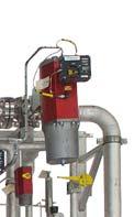
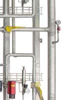
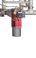
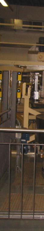
25 DIET Picture DIET Infeed Tobacco DIET Product


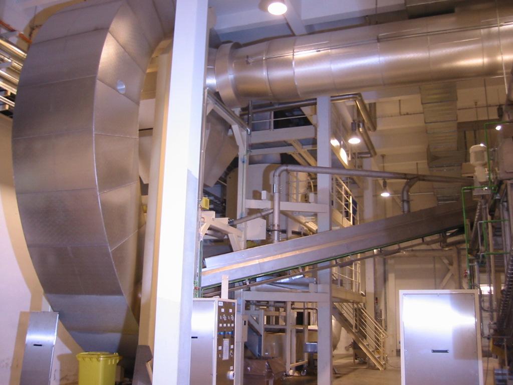
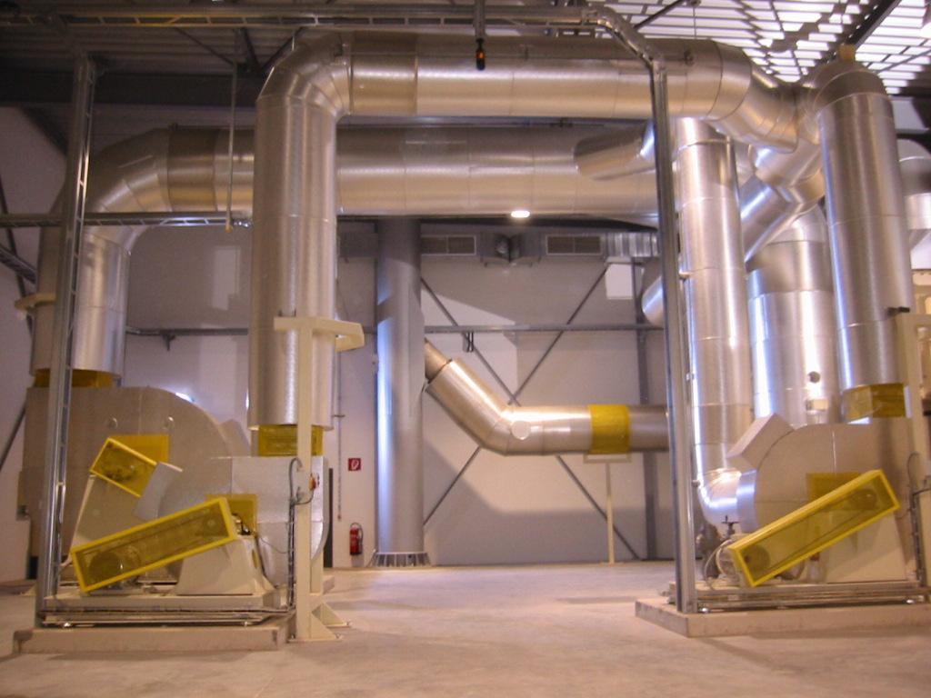
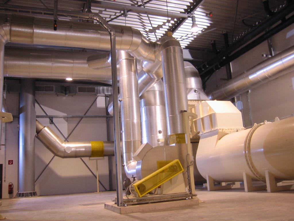
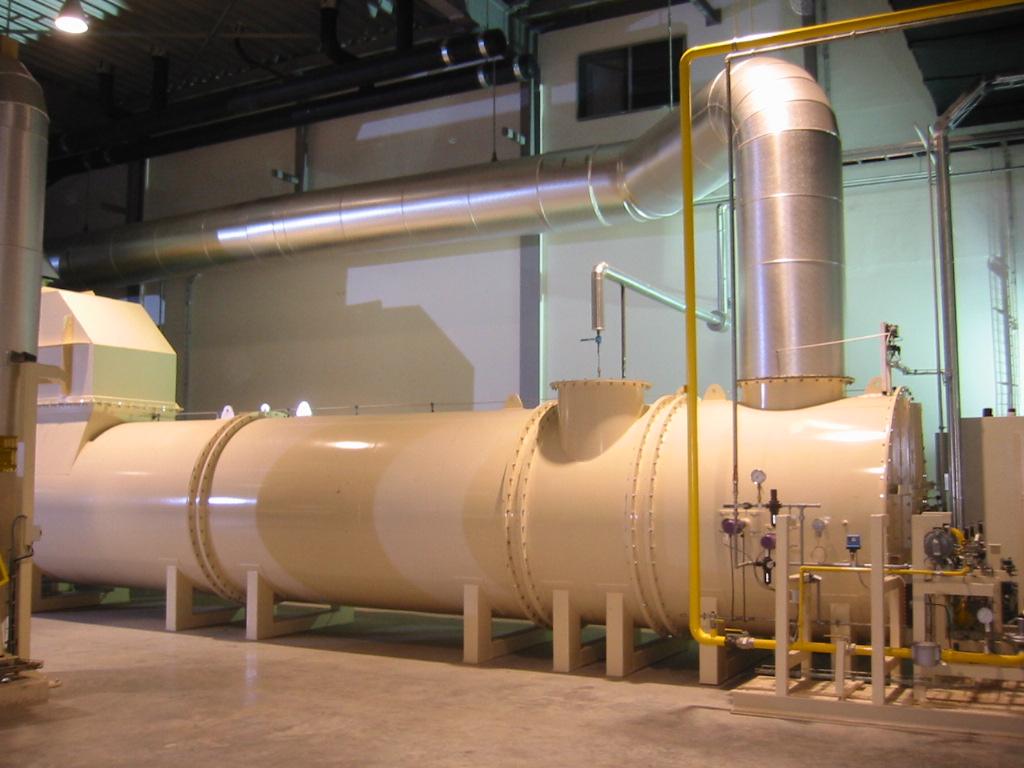
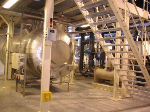
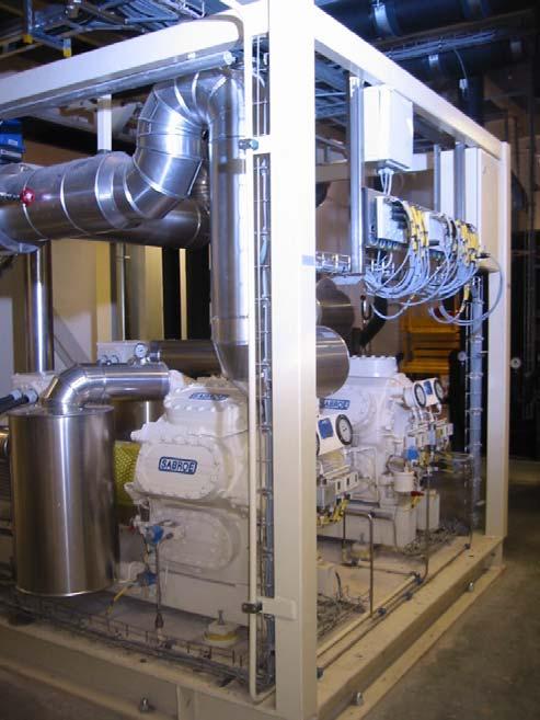
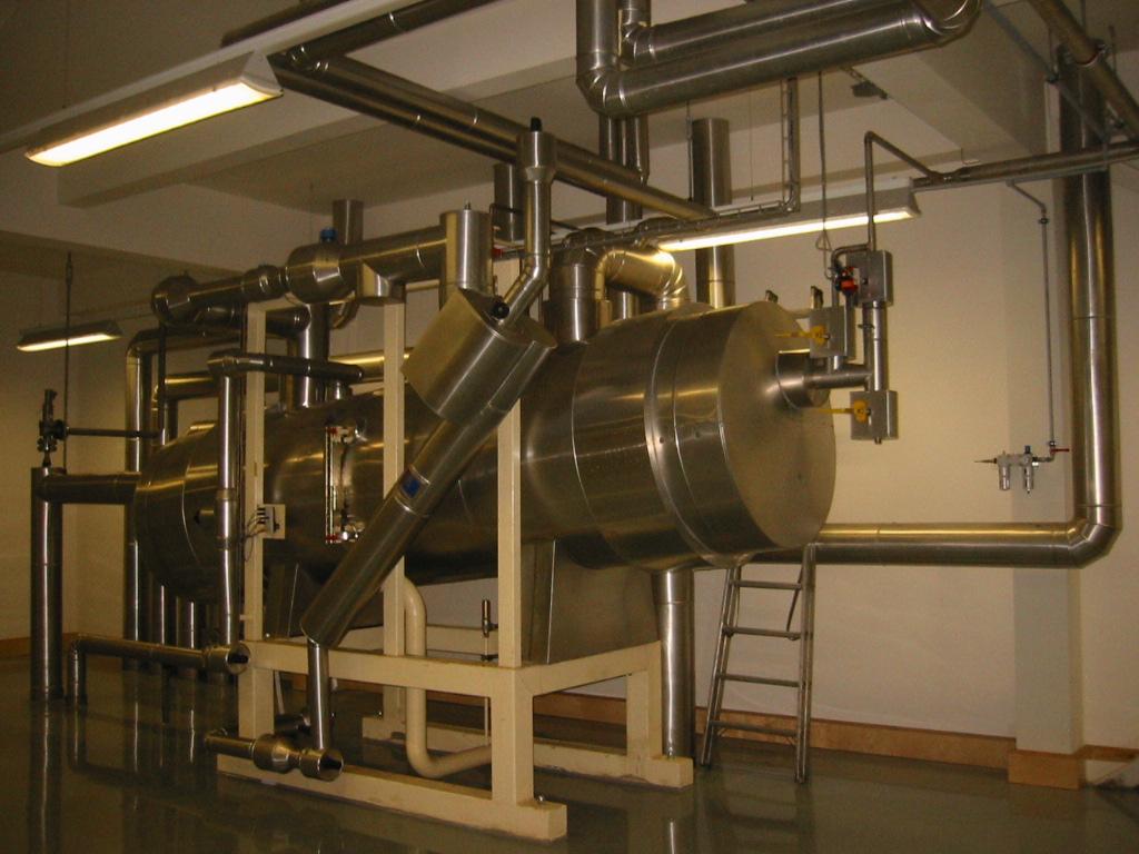
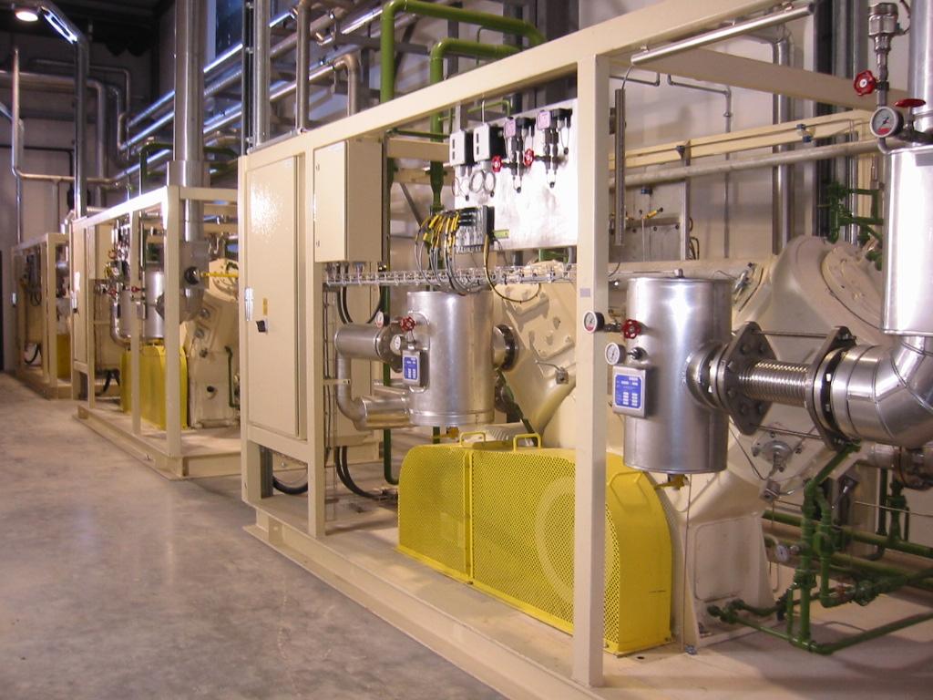
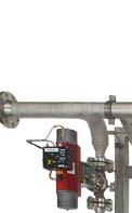
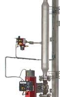
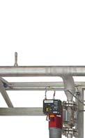
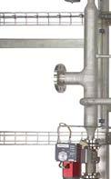
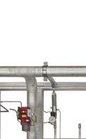
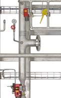
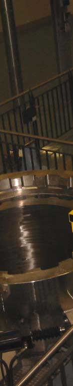
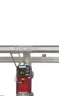
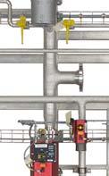
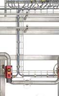
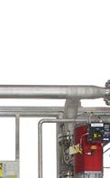
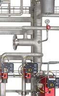
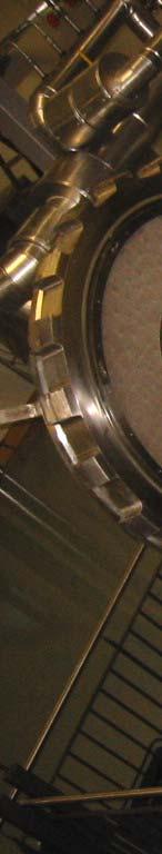
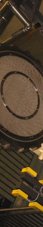
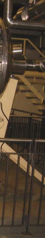
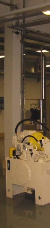
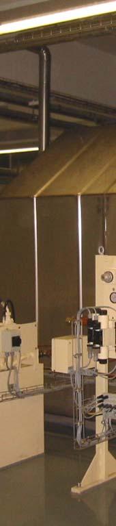
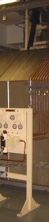
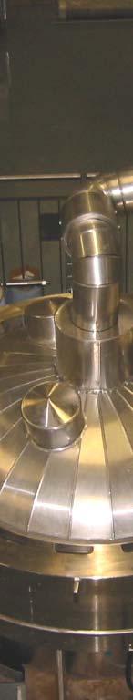
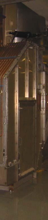
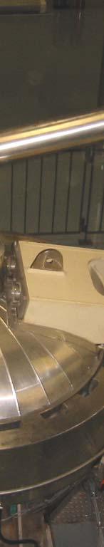
26 Pictures from Airco DIET installations:
27
28
29


30


31


32
ADVANCED Series 15P1 17P2 19P2
 A WIRTGEN GROUP COMPANY Continuous Mobile Asphalt Plants ADVANCED Series 15P1 17P2 19P2 02 03 The Advanced plants line combines the maximum portability of a continuous production plant with the quality
Pulse Jet Baghouse ASTEC PULSE JET BAGHOUSE. for Asphalt Facilities
 Pulse Jet ASTEC PULSE JET BAGHOUSE for Asphalt Facilities ASTEC PULSE JET BAGHOUSE FOR ASPHALT MIXING PLANTS Astec baghouses deliver superior performance and efficiency, while helping your plant meet
ROTARY DRYER CONSTRUCTION
 ROTARY DRYER The Rotary Dryer is a type of industrial dryer employed to reduce or to minimize the liquid moisture content of the material it is handling by bringing it into direct contact with a heated
HOW TO SELECT AN INDIRECT THERMAL TECHNOLOGY FOR INDUSTRIAL MATERIALS PROCESSING
 white paper HOW TO SELECT AN INDIRECT THERMAL TECHNOLOGY FOR INDUSTRIAL MATERIALS PROCESSING Better Thermal Processing Results Begin with Selecting the Right Technology Authored by Rob Grady Director of
2How does a vibratory fluid-bed dryer work?
 As appeared in April 2011 PBE Copyright CSC Publishing www.powderbulk.com Answers to five common questions about vibratory fluid-bed dryers Doug Schieber Carrier Vibrating Equipment A vibratory fluid-bed
Industrial Dust Aspiration Solutions. For optimal protection of plant and environment.
 Bühler GmbH DE-92339 Beilngries Deutschland T + 49 8461 701 0 F +49 8461 701 133 grain-logistics@buhlergroup.com Buhlergroup.com/grain-logistics GL_CB_Dust_Aspriation_Systems_EN_14004_02 Dust Aspiration
ANNEXURE-A SPECIFICATIONS FOR HOT MIX PLANT
 ANNEXURE-A SPECIFICATIONS FOR HOT MIX PLANT COLD AGGREGATE BIN FEEDER FEEDING HOPPERS Four Nos. Cold aggregates hopper with a heaped capacity of approx. 52 T. Wide opening bin width to accommodate different
CLEACOM Engineered System Solutions. Established 24/7 technology for the separation of dust and fume during compounding processes
 CLEACOM Engineered System Solutions Established 24/7 technology for the separation of dust and fume during compounding processes Reduced consumption of resources with dry separation. Wet separation with
ASPHALT PLANT. atlasindustries.in
 ASPHALT PLANT Available as stationary and mobile. STATIONARY VARIANTS: DM 45 (40-60 tph), DM 50 (60-90 tph), DM 60 (90-120 tph) MOBILE VARIANTS: MDM 45 (40-60 tph), MDM 50 (60-90 tph), MDM 60 (90-120 tph)
DM 45 (40-60 TPH) ASPHALT DRUM MIX PLANT - DM 50 (60-90 TPH) I TECHNICAL SPECIFICATIONS DM 60 ( TPH) COLD AGGREGATE FEEDER.
 ASPHALT DRUM MIX PLANT - DM 50 (60-90 TPH) I TECHNICAL SPECIFICATIONS DM 60 ( TPH) COLD AGGREGATE FEEDER.") DM 45 (40-60 TPH) ASPHALT DRUM MIX PLANT - DM 50 (60-90 TPH) I TECHNICAL SPECIFICATIONS DM 60 (90-120 TPH) ROAD BUILDING COLD AGGREGATE FEEDER Stationary four bin cold aggregate feeder unit is with each
DM 45 (40-60 TPH) ASPHALT DRUM MIX PLANT - DM 50 (60-90 TPH) I TECHNICAL SPECIFICATIONS DM 60 (90-120 TPH) ROAD BUILDING COLD AGGREGATE FEEDER Stationary four bin cold aggregate feeder unit is with each
ASPHALT DRUM MIX PLANT - MDM 25 (20-30 TPH) I TECHNICAL SPECIFICATIONS COLD AGGREGATE FEEDER
 I TECHNICAL SPECIFICATIONS COLD AGGREGATE FEEDER") ASPHALT DRUM MIX PLANT - MDM 25 (20-30 TPH) I TECHNICAL SPECIFICATIONS ROAD BUILDING COLD AGGREGATE FEEDER 2 x 2 bin aggregate feeder unit is with total capacity of 20 T. Gathering cum slinger conveyor
ASPHALT DRUM MIX PLANT - MDM 25 (20-30 TPH) I TECHNICAL SPECIFICATIONS ROAD BUILDING COLD AGGREGATE FEEDER 2 x 2 bin aggregate feeder unit is with total capacity of 20 T. Gathering cum slinger conveyor
ASPHALT PLANT. atlastechnologiesindia.com. MOBILE VARIANTS: MDM 45 (40-60 tph), MDM 50 (60-90 tph), MDM 60 ( tph)
, MDM 50 (60-90 tph), MDM 60 ( tph)") ASPHALT PLANT Available as stationary and mobile. STATIONARY VARIANTS: DM 45 (40-60 tph), DM 50 (60-90 tph), DM 60 (90-120 tph) MOBILE VARIANTS: MDM 45 (40-60 tph), MDM 50 (60-90 tph), MDM 60 (90-120 tph)
ASPHALT PLANT Available as stationary and mobile. STATIONARY VARIANTS: DM 45 (40-60 tph), DM 50 (60-90 tph), DM 60 (90-120 tph) MOBILE VARIANTS: MDM 45 (40-60 tph), MDM 50 (60-90 tph), MDM 60 (90-120 tph)
Ashirwad Carbonics (India) Private Limited
 Private Limited") Ashirwad Carbonics (India) Private Limited Co2 Production Plant Technical Literature Our precision engineered range of CO2 Generation Plant is available in various capacities and models as per the clients
Ashirwad Carbonics (India) Private Limited Co2 Production Plant Technical Literature Our precision engineered range of CO2 Generation Plant is available in various capacities and models as per the clients
ASPHALT PLANT. atlastechnologiesindia.com
 ASPHALT PLANT MOBILE PLANT VARIANT: MDM 25 (20-30 tph) atlastechnologiesindia.com AGGREGATE FEEDING CONVEYOR AGGREGATE FEEDER In our mobile asphalt drum mix plant all the four bins are fitted with individual
CPVS PRODUCT DESCRIPTION
 CPVS 20 30 PRODUCT DESCRIPTION The CHICAGO PNEUMATIC CPVS 20-30 compressor is a quiet, complete and ready-for-use unit for the production of compressed air for light and medium industrial applications.
Komline-Sanderson Paddle Dryer. Drying technology for biosolids, sludges and by-products
 Komline-Sanderson Paddle Dryer Drying technology for biosolids, sludges and by-products Why dry? There are economic and environmental benefits to drying biosolids, sludges and by-products. In municipal
ASPHALT PLANT. AtlasTechnologiesIndia.com
 ASPHALT PLANT Available as stationary and semi-mobile. VARIANTS: ABP 80 (80 tph), ABP 120 (120 tph), ABP 160 (160 tph) Capacities above 160 tph are tailor made. AtlasTechnologiesIndia.com AGGREGATE FEEDER
SAMPLE SPECIFICATION FOR RIELLO ARRAY MODULATING BOILER
 SAMPLE SPECIFICATION FOR RIELLO ARRAY MODULATING BOILER PART 1 GENERAL 1.01 RELATED DOCUMENTS A. ANSI Z21.13 American National Standard for Gas-Fired Low Pressure Steam and Hot Water Boilers B. ASME Section
ecodry Figure 1 - Process Diagram ecodry B General Process Description
 ecodry The process principal of the ecodry system is centered around the concept of drying in a closed steam loop, with a process-integrated thermal oxidation. The separation of flue gas from the drying
ASPHALT DRUM MIX PLANT - MDM 25 (20-30 TPH) I TECHNICAL SPECIFICATIONS COLD AGGREGATE FEEDER. Gathering cum slinger conveyor 500 mm x 7.
 I TECHNICAL SPECIFICATIONS COLD AGGREGATE FEEDER. Gathering cum slinger conveyor 500 mm x 7.") ASPHALT DRUM MIX PLANT - MDM 25 (20-30 TPH) I TECHNICAL SPECIFICATIONS ROAD BUILDING COLD AGGREGATE FEEDER 2 x 2 bin aggregate feeder unit is with total capacity of 20 T. Gathering cum slinger conveyor
ASPHALT DRUM MIX PLANT - MDM 25 (20-30 TPH) I TECHNICAL SPECIFICATIONS ROAD BUILDING COLD AGGREGATE FEEDER 2 x 2 bin aggregate feeder unit is with total capacity of 20 T. Gathering cum slinger conveyor
ASPHALT PLANT. MOBILE VARIANTS: MDDM 45 (40-60 tph), MDDM 50 (60-90 tph), MDDM 60 ( tph) atlasindustries.in
, MDDM 50 (60-90 tph), MDDM 60 ( tph) atlasindustries.in") ASPHALT PLANT Available as stationary and mobile. STATIONARY VARIANTS: DDM 45 (40-60 tph), DDM 50 (60-90 tph), DDM 60 (90-120 tph) MOBILE VARIANTS: MDDM 45 (40-60 tph), MDDM 50 (60-90 tph), MDDM 60 (90-120
ASPHALT PLANT Available as stationary and mobile. STATIONARY VARIANTS: DDM 45 (40-60 tph), DDM 50 (60-90 tph), DDM 60 (90-120 tph) MOBILE VARIANTS: MDDM 45 (40-60 tph), MDDM 50 (60-90 tph), MDDM 60 (90-120
Refrigerated Compressed Air Dryers
 Refrigerated Compressed Air Dryers 5-6,000 scfm.14-170 m 3 /min Refrigerated Non-Cycling Refrigerated Cycling Refrigerated High Temperature OWS - 210 Sullair Capabilities Sullair Leadership Since 1965,
DIRECTIVE NO: D-B
 DIRECTIVE NO: D-B6 100604 1 LOW PRESSURE THERMAL FLUID PLANT AUTOMATED CONTROL SYSTEMS Date of Issue: June 4, 2010 General Details This directive is being issued to owners, licensed contractors, consulting
BLAST-IT-ALL BUMPER BLASTER
 LARRY HESS AND ASSOCIATES, INC 185 PIPER LANE / SALISBURY, NC 28147 PHONE: 1-800-535-2612 / FAX: 1-704-638-9311 WWW.BLAST-IT-ALL.COM BLAST-IT-ALL BUMPER BLASTER SUCTION BLAST CABINET NOTE: It is the responsibility
CPF PRODUCT DESCRIPTION
 CPF 175 340 PRODUCT DESCRIPTION The CHICAGO PNEUMATIC CPF 175-340 compressor is a quiet, complete and ready-for-use unit for the production of compressed air in industrial applications. OVERVIEW The CHICAGO
ASPHALT PLANT. atlastechnologiesindia.com. MOBILE VARIANTS: MDDM 45 (40-60 tph), MDDM 50 (60-90 tph), MDDM 60 ( tph)
, MDDM 50 (60-90 tph), MDDM 60 ( tph)") ASPHALT PLANT Available as stationary and mobile. STATIONARY VARIANTS: DDM 45 (40-60 tph), DDM 50 (60-90 tph), DDM 60 (90-120 tph) MOBILE VARIANTS: MDDM 45 (40-60 tph), MDDM 50 (60-90 tph), MDDM 60 (90-120
ASPHALT PLANT Available as stationary and mobile. STATIONARY VARIANTS: DDM 45 (40-60 tph), DDM 50 (60-90 tph), DDM 60 (90-120 tph) MOBILE VARIANTS: MDDM 45 (40-60 tph), MDDM 50 (60-90 tph), MDDM 60 (90-120
Installation Summary - Dairy Plant
 Installation Summary - Dairy Plant Project Summary: Logicon provided an combined automation system for re-automation of 2 Large Milk dryers, replacing existing obsolete systems. Each system was built using
Boiler Basics. Design and operation
 Boiler Basics Design and operation A boiler is an enclosed vessel that provides a means for combustion heat to be transferred into water until it becomes heated water or steam. The hot water or steam under
CPC PRODUCT DESCRIPTION
 CPC 40 60 PRODUCT DESCRIPTION The CHICAGO PNEUMATIC CPC 40-60 compressor is a quiet, complete and readyfor-use unit for the production of compressed air in industrial applications. OVERVIEW The CHICAGO
SPRAY DRYING SYSTEMS INC.
 SPRAY DRYING SYSTEMS INC. Spray Drying Systems, Inc. Cover photos: (large photo) This co-current, parallel flow spray dryer produces a 300 micron average particle size with no buildup. This demonstrates
Quality Construction Equipment
 Quality Construction Equipment ASPHALT BATCH MIX PLANT ANP Series - 60 to 240 tph ASPHALT BATCH MIX PLANT Apollo has always been proactive in rising to customer demands and expectations by providing quality
Acrison. Polymair. Model 500 Polyelectrolyte Preparation System. For Dry and Liquid Polymers. Industrial and municipal chemical feed equipment.
 Acrison Bulletin 500 Polymair Model 500 Polyelectrolyte Preparation System For Dry and Liquid Polymers Industrial and municipal chemical feed equipment. Acrison Polymair Model 500 Acrison Polyelectrolyte
Improved Dryer Control
 Improved Dryer Control Kenneth C. Hill President Kadant Johnson Systems Division David Vijh Senior Process Control Engineer Technical White Paper Series EXECUTIVE SUMMARY Significant improvements in dryer
Acrison. Model 515 Polyelectrolyte Preparation Module. For Dry and Liquid Polymers. Industrial and municipal chemical feed equipment.
 Acrison Bulletin 515 Model 515 Polyelectrolyte Preparation Module For Dry and Liquid Polymers Industrial and municipal chemical feed equipment. Acrison Model 515 Acrison Packaged Polyelectrolyte Acrison
CENTRIFUGAL PUMPS. STATE the purposes of the following centrifugal pump components:
 Pumps DOE-HDBK-1018/1-93 CENTRIFUGAL PUMPS CENTRIFUGAL PUMPS Centrifugal pumps are the most common type of pumps found in DOE facilities. Centrifugal pumps enjoy widespread application partly due to their
REFRESH, UPGRADE, PERFORM. Revamping Kits and Digital Solutions for quality improvement and energy savings
 Revamping Kits and Digital Solutions for quality improvement and energy savings Burners Sacmi for energy savings Complete range of burners for all fuel types. Heads specially designed for different capacities
SEMICONDUCTOR FABRICATION FACILITIES
 CHAPTER 18 SEMICONDUCTOR FABRICATION FACILITIES SECTION 1801 GENERAL 1801.1 Scope. Semiconductor fabrication facilities and comparable research and development areas classified as Group H-5 shall comply
TMCI Padovan Evaporators
 TMCI Padovan Evaporators Evaporators Our range includes 4 types of evaporators: Forced Circulation Falling Film Evaporators Plates Thin Film Concentration systems Evaporator choosing criteria: product
Boiler Technical Specifications (2013)
") ACT Bioenergy Boiler Dimensions 0.5-0.85 Million Btu/h (150-250kW) Model CP500 CP600 CP750 CP850 Heat Output in MBtu/h (kw) 510 (150) 610 (180) 750 (220) 850 (250) Height ft (mm) 6 1 (1855) 6 1 (1855)
ACT Bioenergy Boiler Dimensions 0.5-0.85 Million Btu/h (150-250kW) Model CP500 CP600 CP750 CP850 Heat Output in MBtu/h (kw) 510 (150) 610 (180) 750 (220) 850 (250) Height ft (mm) 6 1 (1855) 6 1 (1855)
BlendingLine. MINICOLOR V MINICOLOR G GRAVICOLOR Dosing and mixing units. smart solutions
 BlendingLine smart solutions MINICOLOR V MINICOLOR G GRAVICOLOR Dosing and mixing units Excellent mixing quality with highest repeatability are demanding requirements when dosing additives and regrind
Refrigerated Compressed Air Dryers 5-6,000 scfm
 Refrigerated Compressed Air Dryers 5-6,000 scfm Refrigerated Non-Cycling Refrigerated Cycling Refrigerated High Temperature OWS - 210 Sullair Capabilities Sullair Leadership Since 1965, Sullair has been
AMERICAN EQUIPMENT SYSTEMS A Division Of Trevor-Martin Corporation th Terrace North Clearwater, Florida 33762
 AMERICAN EQUIPMENT SYSTEMS A Division Of Trevor-Martin Corporation 4151 112 th Terrace North Clearwater, Florida 33762 COMMERCIAL REFRIGERANT DESUPERHEATER WASTE HEAT RECOVERY INSTALLATION/OPERATION/MAINTENANCE
A Design for True Performance and Energy Savings In Refrigerated Compressed Air Dryers The Digital Scroll Dryer
 A Design for True Performance and Energy Savings In Refrigerated Compressed Air Dryers The Digital Scroll Dryer Introduction By Timothy J. Fox, P.E. Hankison, an SPX Brand Canonsburg, Pennsylvania Refrigerated
TOWER DRYERS TOTA TOT L VA AL V LUE. TOTA ALUE. TOT L SYSTEMS. AL SYSTEMS.
 TOWER DRYERS TOTAL VALUE. TOTAL SYSTEMS. 1 GSI FEATURES 1 Gravity inlet does not require leveling auger, reducing the number of moving parts. 2 3 2 Self cleaning cushion box on plenum roof reduces grain
Division III Process Gas Treatment Equipment
 ASME AG-1 Committee on Nuclear Air and Gas Treatment Division III Process Gas Treatment Equipment Chairman, SC Gas Process Treatment August 2008 - p 1 ASME AG-1 Division I General Requirements Division
For inspection purposes only.
 Attachment F.1 Neutralisation System Process Description The CPG process generates both acid and caustic waste water from the acid/base leaching processes. This waste water will be collected in dedicated
Operator s Manual. Linear Asphalt Compactor. Jesse D. Doyle Isaac L. Howard, PhD Mississippi State University. January 2010 CMRC M 10-1 Version 1
 Operator s Manual Linear Asphalt Compactor Mississippi Department of Transportation Jesse D. Doyle Isaac L. Howard, PhD Mississippi State University An Industry, Agency & University Partnership January
FS 231: Final Exam (5-6-05) Part A (Closed Book): 60 points
 Part A (Closed Book): 60 points") Name: Start time: End time: FS 231: Final Exam (5-6-05) Part A (Closed Book): 60 points 1. What are the units of the following quantities? (10 points) a. Enthalpy of a refrigerant b. Dryness fraction of
Name: Start time: End time: FS 231: Final Exam (5-6-05) Part A (Closed Book): 60 points 1. What are the units of the following quantities? (10 points) a. Enthalpy of a refrigerant b. Dryness fraction of
CHAPTER 2 EXPERIMENTAL APPARATUS AND PROCEDURES
 CHAPTER 2 EXPERIMENTAL APPARATUS AND PROCEDURES The experimental system established in the present study to investigate the transient flow boiling heat transfer and associated bubble characteristics of
New rotary batch blender cleans up company's testing process
 DRY BULK BLENDING EQUIPMENT Rotary Batch Mixers Ribbon/Paddle/ Plow Blenders Rotary Continuous Blenders High Intensity Continuous Blenders Vee-Cone Blenders Fluidized Bed Mixers SIZE REDUCTION EQUIPMENT
IRD INFRARED ROTARY DRUM HEATING. DRYING. CRYSTALLIZING. COATING.
 IRD INFRARED ROTARY DRUM HEATING. DRYING. CRYSTALLIZING. COATING. MINIMAL PROCESSING TIMES HIGH FLEXIBILITY LOW ENERGY CONSUMPTION KREYENBORG is a leading provider of solutions in the field of bulk material
HIGH CAPACITY PRODUCT LINE
 HIGH CAPACITY PRODUCT LINE Highest Quality, Best Service Manufacturing chlorination equipment and related products since 1978 PROUDLY MADE IN USA 600 Emlen Way, Telford, PA 18969 Telephone: (215) 799-0980
INSTALLATION, OPERATING & MAINTENANCE INSTRUCTIONS FOR 350 SERIES CIRCULATION HEATERS
 INDEECO Circulation Heaters are designed to provide years of trouble free operation if properly installed and maintained. Please read and follow these instructions for installing and maintaining the heater.
UNIVERSAL SERIES COMBINATION SHREDDER-FEEDER-EXTRUDER X:GRAN.
 UNIVERSAL SERIES COMBINATION SHREDDER-FEEDER-EXTRUDER X:GRAN > ONE-STEP technology > Process bulky plastic scrap > One-button automatic On/Off control > DUMP and RUN operation www.ngr.at TECHNOLOGY THE
1.1 This section applies to air handling units for HVAC Systems.
 AIR HANDLING UNITS GENERAL INFORMATION 1.1 This section applies to air handling units for HVAC Systems. DESIGN REQUIREMENTS 2.1 Design Criteria a. The decision to use modular central station air handling
By Authority Of THE UNITED STATES OF AMERICA Legally Binding Document
 By Authority Of THE UNITED STATES OF AMERICA Legally Binding Document By the Authority Vested By Part 5 of the United States Code 552(a) and Part 1 of the Code of Regulations 51 the attached document has
PURGER INSTALLATION AND OPERATION BULLETIN PUR-SB17-02 SERVICE BULLETIN
 VALVES VESSELS SYSTEMS CONTROLS PURGER INSTALLATION AND OPERATION BULLETIN PUR-SB17-02 SERVICE BULLETIN System drawings shown in this bulletin are for illustration purposes only. Refrigeration systems
Part I Extraction Process Equipment
 745 West Colfax Avenue Denver, CO 80204 p: 720.913.3474 f: 720.913.3596 www.denvergov.org/fire MARIJUANA EXTRACTION GUIDELINE FOR COMMERCIAL / LICENSED FACILITIES The information contained within this
Climate Control System
 Page 1 of 13 SECTION 412-00: Climate Control System General Information DESCRIPTION AND OPERATION 1998 Mark VIII Workshop Manual Climate Control System Cautions and Warnings WARNING: To avoid accidental
Asphalt plants Soil stabilization plants Cold asphalt plants Concrete plants
 Asphalt plants Soil stabilization plants Cold asphalt plants Concrete plants QUALITY, RELIABILITY AND SAFETY More than 50 years of experience M-260 asphalt plant. index The Company 4 Batch type asphalt
Experienced Worker Assessment Blueprint HVAC - Heating, Ventilation and Air Conditioning
 Blueprint HVAC - Heating, Ventilation and Air Conditioning Test Code: 0144 / Version: 02 Specific Competencies and Skills Tested in this Assessment: Electricity Demonstrate understanding of basic AC/DC
Power Flame Incorporated
 Power Flame Incorporated SUGGESTED SPECIFICATION FOR MODEL NVC ULTRA LOW NOx GAS BURNERS SUB 9 PPM NOx THE POWER TO MANAGE ENERGY 2001 South 21st Street, Parsons, Kansas 67357 Telephone: 620-421-0480,
OPERATION OF LAFER SOLVENT SCOURING PLANT
 OPERATION OF LAFER SOLVENT SCOURING PLANT INDEX Operation principle... page 2 Machine attachments... page 3 Plant service s... page 4 Machine start-up and stop... page 5 Safety systems of plant... page
Direct Fired Heater Model AD Specification
 Direct Fired Heater Model AD Specification Description A Direct-fired gas heating and ventilating unit(s), as indicated on the drawings shall be furnished. Unit(s) shall be tested in accordance with ANSI
HIGH CAPACITY PRODUCT LINE
 HIGH CAPACITY PRODUCT LINE Highest Quality, Best Service Manufacturing chlorination equipment and related products since 1978 PROUDLY MADE IN USA 600 Emlen Way, Telford, PA 18969 Telephone: (215) 799-0980
Woody Biomass Fuel Drying
 Information Sheet 12 Woody Biomass Fuel Drying Introduction Extracting useful heat energy from wood involves processing the wood in a combustor or a gasifier. Prior to combustion it can be left to dry
Cone Calorimeter. (ISO 5660 ASTM E 1354) The most comprehensive bench scale fire test THE BENCHMARK IN FIRE TESTING
 The most comprehensive bench scale fire test THE BENCHMARK IN FIRE TESTING") Cone Calorimeter (ISO 5660 ASTM E 1354) The most comprehensive bench scale fire test THE BENCHMARK IN FIRE TESTING Cone Calorimeter (ISO 5660 ASTM E 1354) The most comprehensive bench scale fire test The
Cone Calorimeter (ISO 5660 ASTM E 1354) The most comprehensive bench scale fire test THE BENCHMARK IN FIRE TESTING Cone Calorimeter (ISO 5660 ASTM E 1354) The most comprehensive bench scale fire test The
OPERATING AND MAINTENANCE MANUAL FOR PLATE HEAT EXCHANGER INDIRECT FIRED WATER HEATER. Electric Heater Company Base Model "BWXP"
 OPERATING AND MAINTENANCE MANUAL FOR PLATE HEAT EXCHANGER INDIRECT FIRED WATER HEATER Electric Heater Company Base Model "BWXP" HUBBELL ELECTRIC HEATER COMPANY P.O. BOX 288 STRATFORD, CT 06615 PHONE: (203)
Beneficial Use of Landfill Gas for Leachate Evaporation and Power Generation
 Beneficial Use of Landfill Gas for Leachate Evaporation and Power Generation Efficient use of Energy Turning waste to energy, liabilities to assets and visions into reality. Table of Contents BENEFICIAL
Internal ridged board 1" x 1.5 foil face installation shall be installed on roof, walls and base of casing.
 A-D WITH MPU SPECIFICATION WRITTEN SPECIFICATION Description A Modular Packaged Heating, Cooling and ventilating unit(s), as indicated on the drawings shall be furnished. Direct Fired Gas Unit(s) shall
EN l Senking Batch Transfer Drying Tumbler DT Senking Batch Transfer Drying Tumbler DT High performance with less energy
 EN l Senking Batch Transfer Drying Tumbler DT 60 240 Senking Batch Transfer Drying Tumbler DT 60 240 High performance with less energy Single dryer with loading belt. directly side by side. The dryers
AQUA LOW-MEDIUM SPEED BOTTLE WASHER
 AQUA LOW-MEDIUM SPEED BOTTLE WASHER BOTTLEWASHER AQUA WASHING CYCLE THE WASHING CYCLE CONSISTS OF FOUR DISTINCT PHASES. Pre-wash The pre-soaking stage takes place in one or two stages; after leaving the
ClearFire Economizer Model ECF Integral or External. Addendum to manuals CFH and CFV
 ClearFire Economizer Model ECF Integral or External Addendum to manuals 750-295 CFH and 750-269 CFV CB-8466 08/2011 1-GENERAL The Model ECF economizer is a stainless steel coil tube arrangement using
ALDRICH COMPANY THREE PASS FIRETUBE BOILER CLASSIC SERIES OPERATING & MAINTENANCE MANUAL
 ALDRICH COMPANY THREE PASS FIRETUBE BOILER CLASSIC SERIES OPERATING & MAINTENANCE MANUAL ALDRICH COMPANY 341 EAST WILLIAMS ST WYOMING, IL 61491 PH: 309-695-2311 FAX: 309-695-5779 1 General Information:
LMV52 Control. Specifications. Document No. LV February 3, Product Description. Sample Specification
 LMV52 Control Product Description February 3, 2017 The LMV52 is a microprocessor-based burner management system with matching system components for the control and supervision of forced draft burners.
2x58 MW Coal Fired Power Plant at Mauritius
 2x58 MW Coal Fired Power Plant at Mauritius The coal-fired power plant produces electricity by the burning of coal and air in a Circulating Fluidized Bed Combustion Boiler (CFBC), where it heats water
WASHING CYCLE. In the most sophisticated machine Version (DH 3), all the following steps are included.
, all the following steps are included.") HYDRA BOTTLE WASHER HYDRA The Hydra bottle washer has been designed for mediumhigh speed production (from 30,000 bph up to 120,000 bph 500 ml bottles) and particularly for those clients who are better
HYDRA BOTTLE WASHER HYDRA The Hydra bottle washer has been designed for mediumhigh speed production (from 30,000 bph up to 120,000 bph 500 ml bottles) and particularly for those clients who are better
B. Use UT Austin specifications and equipment schedule format for HVAC equipment where available.
 PART 1: GENERAL 1.01 General Requirements A. This standard is intended to provide useful information to the Professional Service Provider (PSP) to establish a basis of design. The responsibility of the
SECTION AIR COMPRESSORS AND ACCESSORIES
 PART 1 GENERAL 1.01 WORK INCLUDED SECTION 11370 AIR COMPRESSORS AND ACCESSORIES A. This specification includes air compressors with air dryers. B. Furnish, install, start-up, and test air compressors and
International Reactor Bulletin 1100 Corporation. Standard and Custom Reactors for the Chemical Process Industries
 International Reactor Bulletin 1100 Corporation Standard and Custom Reactors for the Chemical Process Industries 2 International Reactor Corporation 521 Kiser Street Dayton, Ohio 45404-1641 Phone: 937-224-4444
Vacuum System Troubleshooting Author: Keith Webb, P.E. Application Engineering Manager
 INTRODUCTION The science of creating vacuum is often misunderstood and when the desired vacuum condition is not being achieved in a manufacturing setting this usually means production comes to a halt and
Pneumatic Vacuum Conveyors for the Highest Standards Transportation of bulk materials in the pharmaceutical and chemical industries
 Pneumatic Vacuum Conveyors for the Highest Standards Transportation of bulk materials in the pharmaceutical and chemical industries VOLKMANN Inc. In process technology there is a frequent requirement for
This series is utilized for waste streams which are not prone to hardening in the presence of liquid solvent, and provides ease of residue removal.
 The SRV-Series is designed for system sizes handling 25-250 gallons per hour and is the simplest and highest performance system design in its price range. It is composed of a non-scraped vessel with a
E-16 Main Engine Remote Control System
 Guideline No.E-16 (201510) E-16 Main Engine Remote Control System Issued date: 20 October, 2015 China Classification Society Foreword This Guide is a part of CCS Rules, which contains technical requirements,
DUST COLLECTION TRAINING. Revision 2013
 DUST COLLECTION TRAINING Revision 2013 TOPICS 1. Why does a school need a dust collector? 2. What is a dust collection system? 3. What are the maintenance requirements? 4. What are the hazards? WHY NFPA
OCEANO BOTTLE WASHER
 OCEANO BOTTLE WASHER OCEANO In the effort to reduce the environmental impact of waste from industrial production, there is an increasingly deeplyfelt need to recover empty containers, such as glass or
SEMICONDUCTOR FABRICATION FACILITIES
 CHAPTER 18 SEMICONDUCTOR FABRICATION FACILITIES SECTION FC 1801 GENERAL 1801.1 Scope. This chapter shall govern the design, installation, operation and maintenance of semiconductor fabrication facilities
AEC Sales & Support Research Equipment Phone Fax East Main Street
 Research Equipment Research Accessories and Equipment COB INCLINE CONVEYOR AND COB BIN - Incline belt conveyors are designed to transfer cobs into a cob bin for convenient disposal. Cob incline conveyor
When did this technology start?
 When did this technology start? ACB, a French shipbuilding company, developed the continuous technology in the early 70 s when they were asked to design a sterilization solution on board a fishing ship.
Technique and common sense to the expertise
 Textile catalogue Technique and common sense to the expertise For more than 30 years, TECHNIC ONE is specialized in the realization of turn-key projects. Our philosophy is to support you throughout your
I&C Upgradation and Modernization at CHASNUPP 1 & 2. Presented By: Waseem Uddin Farooqi PAEC, Pakistan
 I&C Upgradation and Modernization at CHASNUPP 1 & 2 Presented By: Waseem Uddin Farooqi PAEC, Pakistan Contents of Presentation Nuclear Power in Pakistan I&C Overview of CHASNUPP-1 & 2 (C-1 & C-2) I&C Upgradation
Wallace & Tiernan Gas Feed Systems V2000 Chlorinator
 Wallace & Tiernan Gas Feed Systems V2000 Chlorinator Introduction Siemens Water Technologies chlorination equipment has the benefit of 100 years of experience in gas feed technology. V2000 chlorinators
Refrigeration air dryer
 Principle of refrigeration air dryer Pneumatic circuit (System diagram) Warm wet water is precooled by compressed air chilled and dehumidified by air balancer (A) (precooler). Precooled compressed air
MINIMUM TANK GAP. Greater of 3 or one-sixth of sum of adjacent tank diameters. one-half of sum of adjacent tank diameters 20
 Piping Layout Design Introduction The performance requirements of the equipment are developed by design teams which normally include members from the different departments such as process, engineering,
SEMICONDUCTOR FABRICATION FACILITIES
 CHAPTER 18 SECTION 1801 GENERAL 1801.1 Scope. Semiconductor fabrication facilities and comparable research and development areas classified as Group H-5 shall comply with this chapter and the International
Handling Petroleum Products & Static Ignition Hazards Introduction
 Handling Petroleum Products & Static Ignition Hazards Introduction Static electricity in one form or another is a phenomenon of nature and often results in electrostatic discharges that can cause fires
Revitalize Building Mechanical Systems (4619)
") SECTION 235216 FIRE-TUBE CONDENSING BOILERS PART 1 - GENERAL 1.1 RELATED DOCUMENTS A. Drawings and general provisions of the Contract, including General and Supplementary Conditions and Division 01 Specification
SECTION 235216 FIRE-TUBE CONDENSING BOILERS PART 1 - GENERAL 1.1 RELATED DOCUMENTS A. Drawings and general provisions of the Contract, including General and Supplementary Conditions and Division 01 Specification
SECTION PACKAGED, OUTDOOR, CENTRAL-STATION AIR-HANDLING UNITS
 SECTION 237413 - PACKAGED, OUTDOOR, CENTRAL-STATION AIR-HANDLING UNITS PART 1 - GENERAL 1.1 SUMMARY A. This Section includes packaged, outdoor, central-station air-handling units (rooftop units) with the
PRE-BATCHER UNIT DRYER UNIT. Model: RM 350. Year of construction: Composed of:
 Asphalt Plant INTRAME 350 RM Alicante, 24.10.2017 Asphalt Plant INTRAME 350 RM Offer number: A-160509-1994-01 Brand: INTRAME Model: RM 350 Capacity: 350 t/h Year of construction: 1994 Refurbished: 2004
Pneumatic Vacuum Conveying: an Easy Clean, Efficient, and Safe Mode of Transfer for Difficult or Harmful Pharmaceutical Powders
 Pneumatic Vacuum Conveying: an Easy Clean, Efficient, and Safe Mode of Transfer for Difficult or Harmful Pharmaceutical Powders Introduction Powder transfer by pneumatic vacuum conveying has become one