Bulletin (Jan 2011) And User s Guide
|
|
|
- Trevor Mills
- 6 years ago
- Views:
Transcription


1 Bulletin (Jan 2011) Unichiller Installation And User s Guide
2 Customer Service If you have questions about Installation, operation and Maintenance of the Unichiller or would like to order replacement parts please use the following contact information. Customer Service and Technical Support (7 A.M. to 5 P.M. Central Time) Phone: Fax: Web Site Visit to find information about Unico Products 2009 Unico Inc. All rights reserved This document is subject to change without notice 7401 Alabama Ave., Saint Louis, MO
3 Contents General Instructions 1 Placement of the Unichiller 2 Location 2 Clearances 2 Roof Run off 2 Equipment Pad 2 Lawn Irrigation 2 Installations Near Salt Water 3 Electrical 3 Piping 3 Chiller Pump Characteristics 3 Effect Of Water Temperature On Pressure Drop 5 Use of Propylene or Ethylene Glycol 5 Installation 6 Connecting Chiller to Water Circuit 6 Chiller Pump Characteristics 6 Electrical 6 Water Side Only Start up 6 Digital Temperature Controller (DTC) 7 Programming the DTC 7 DTC Trouble Shooting and Error Messages 8 Full System Start up 9 Chiller Maintenance 10 Trouble shooting Guide 11 Chiller Wiring Diagrams 12
4 General Instructions The Unichiller is manufactured to meet US and European electrical requirements. Installation and service must be performed by qualified installer or service agency, and must conform to all national, state, and local codes of the country where it is to be operated. Unichillers have self contained factory charged and tested refrigeration systems containing either R 22 or R407C refrigerants. The type of refrigerant and quantity is listed on the factory information label located on the back panel. It is not necessary to access the refrigeration system for system installation and start up. All Unichillers are tested through a full cooling and heating cycle prior to shipment from the factory. Before operating, be sure the unit is properly grounded to prevent injury or death from electrical shock! Disconnect electrical supply before wiring unit to prevent injury or death from electrical shock! Do not handle the top half of the scroll compressor as it operates at a temperature high enough to cause serious injury.operation of the chiller without proper freeze protection shall void the warranty. Do not operate this system for long periods of time with water alone. A minimum of 10% propylene or ethylene glycol is essential to prevent freezing. Higher concentrations of glycol are required to prevent heat exchanger from rupturing in cold climates. Recommended operating temperatures are 115 F for hot water and 40 F for chilled water. Contact Customer Service if you wish to operate at water temperatures outside of the recommended range. Do not use any liquid solution other than the solution of water and propylene or ethylene glycol in the piping system. The solution must be mixed in accordance with the guidelines in the Unichiller Design Manual. Pump must be primed (free of air and suction pipe full of liquid) before starting. If pump is run dry, rotating parts will seize and mechanical seal will be damaged. All electrical wiring should be in accordance with all local codes and regulations. A field provided electrical disconnect shall be installed. The units are safety certified to safety codes of the country they are sold in (refer to Unichiller Specifications Bulletin for further details). All piping must be in accordance with all local codes and ordinances. Installation should be in accordance with all local codes and regulations. These units are designed to operate with R 22 or R 407C in a self contained, pre charged refrigerant system. Do not access the closed refrigerant system for any reason other than after sale, after installation component replacement. Such service is to be conducted by qualified personnel only. 1
5 Placement of the Unichiller Location Always locate the chiller outdoors. Never install inside a room. Installing the unit in a pit will reduce performance Locate chiller so that ground water will not enter cabinet. In areas with heavy snow fall it is recommended that the unit be elevated. Do not attach duct work to the chiller. If air deflectors are necessary contact Unico Customer Service for instructions. Clearances The chiller must be placed to provide clearances on all sides for maintenance and inspection. TOP VIEW FRONT VIEW 12 inches (0.3 m) air inlet 12 inches (0.3 m) air inlet 6 inches (0.15 m) minimum or 24 inches (0.6 m) for service service access side Overhang 24 inches (0.6 m) 12 inches max (0.3 m) 60 inches (1.5 m) air discharge shrubs or porous wall Maximum height of wall is 4.5 ft (1.4 m) Figure 1: Unichiller Clearances 1. At least 24 must be available on the side of the chiller that accesses the control box, pump and compressor. See Figure Allow at least 60 on the fan side. 3. The remaining two sides should have a minimum clearance of 12 Roof Run off The Unichiller should not be located where large amounts of water may run off from a roof onto or into the unit. Best practices dictate that the chiller be protected from large amounts of run off. Equipment Pad Place the chiller on a flat solid surface such as a concrete or fabricated slab. The slab should be slightly tilted so that condensation from the chiller will run off the slab and not pool around the chiller. Lawn Irrigation Make sure that there are absolutely no sprinkler heads near enough to the chiller that will spray water directly on or into the unit. Keep in mind that prevailing winds may carry mist from sprinklers into the chiller causing damage to electrical connections and mechanical parts. 2
6 Installations Near Salt Water When installing the chiller in coastal areas near salt water it is best to install the chiller so that the building is between the shore and the unit. To improve the lifetime it is best to request a technicoat condenser coil. Electrical All electrical connections supplied to the chiller must meet National and local codes. Check for proper line voltage for the chiller and blower modules if used. Low line voltages may require the use of a soft start upgrade. Check with Customer Service to determine whether or not a soft start upgrade will be necessary. Piping Make sure all pipe sizing conforms to flow requirements. Recommended chiller piping connections is 1 minimum. Air in the piping system can damage the pump seals. Make sure that in the case of a non sealed water storage system that air separators or air vents are placed in inlet side of the piping system. Chiller Pump Characteristics The chiller can be ordered with or without an internal water pump. When installing the chiller to the existing water circuit it may be necessary to trouble shoot the water circuit. Figure 2 outlines important data regarding chiller characteristics with and without the pump to aid in the trouble shooting process. GPM ft.water kpa PSI Pump Curve 30 External Static Pressure (UniChiller with pump) Internal Pressure Drop (UniChiller without pump) UniChiller models UCHR Pressure Difference UCH(R)0604 1,2 2. UCH(R) UCH(R)0604 6,7,8 4. UCH(R)0364 1,2 5. UCH(R) UCH(R)0364 6,7,8 1/60/230V 1/60/264V 1/50/260V GPM L/s Water Flow Rate R0843: Catalog4 6/3/2009 Figure 2. Water flow and pressure differentials for various chiller models. 3
7 Additional information regarding pump characteristics are given in Table 1. Table 1. Pump characteristics based on flow rates and voltage for each of the chiller models. Bolded lettering indicates optimum system values. (English Units) UCHR0364 Options: **0 1*2, 230V 265V 6*2, 7*2, 240V GPM ISP (psi) ESP (psi) SP(psi) Watts Amps ESP (psi) SP(psi) Watts Amps ESP (psi) SP(psi) Watts Amps UCHR0604 Options: **0 1*2, 230V 265V 6*2, 7*2, 240V GPM ISP (psi) ESP (psi) SP(psi) Watts Amps ESP (psi) SP(psi) Watts Amps ESP (psi) SP(psi) Watts Amps (SI Units) UCHR0364 Options: **0 1*2, 230V 265V 6*2, 7*2, 240V L/s ISP (kpa) ESP (kpa) SP(kPa) Watts Amps ESP (kpa) SP(kPa) Watts Amps ESP (kpa) SP(kPa) Watts Amps UCHR0604 Options: **0 1*2, 230V 265V 6*2, 7*2, 240V L/s ISP (kpa) ESP (kpa) SP(kPa) Watts Amps ESP (kpa) SP(kPa) Watts Amps ESP (kpa) SP(kPa) Watts Amps
8 Effect of Water Temperature on Pressure Drop The temperature of the water can affect the pressure drop on the chiller system Table 2 lists the coefficients used to calculate pressure drop due to temperature. Table 2. Pressure Drop Correction Factor Based on Temperature (for water) Temperature F C (0) (4.4) (10) (15.6) (20) (32.2) (37.8) (43.3) (48.9) (54.4) Factor Use of Propylene or Ethylene Glycol The Chiller can reach water temperatures well below freezing. Therefore it is recommended that the water system be charged with a minimum 10% glycol solution. Higher percentages of glycol will be necessary when the chiller is operated in regions of the country where outdoor temperatures fall below freezing. Table 3 gives the recommended glycol percentages depending on the expected low temperatures for the region. Table 3. Percentage of propylene glycol solution necessary to protect chiller system in cold weather. % Propylene Glycol 10% 20% 30% 40% 50% Minimum F Ambient Temperature C The percentage of propylene glycol can affect the pressure drop on the system. Table 4 lists the correction factors recommend to calculate pressure drop based on the percentage of glycol in the system. Table 4. Pressure Drop Correction Factor Based on Percentage of Glycol % Glycol Propylene Glycol Ethylene Glycol
9 Chiller Installation Connecting the chiller to installed plumbing Make sure all pipe sizing conforms to flow requirements. 1. Chiller Piping connections: a. Supply 1 NPT b. Return 11/4 NPT 2. Units without pumps are provided with a flow meter. 3. When attaching piping to chiller double wrench to prevent damage to chiller. 4. Install strainer (supplied to chiller) into return line. 5. Install full port isolation valves in supply and return piping. 6. On multiple chiller installations, install a check valve in supply lines of each chiller. 7. Install all piping valves flow regulators, pumps and storage tanks per system design. 8. Locate all vents at high points of piping system for easy venting. 9. Make accommodations for filling system and adding glycol to system 10% glycol minimum required. Electrical Installation 1. Install line voltage wiring including manual disconnect at unit per local code. 2. See wiring diagram on unit or in documentation packet for specific connection information. 3. Install low voltage control wiring per code. See wiring diagram on unit or in documentation packet for specific information. There are many possible control wiring variations. Consult wiring diagrams in back of bulletin for most common hook ups. Additional wiring information can be obtained by calling Unico customer service at Water Side Only Start Up 1. Remove Service access panel from chiller. Remove chiller top panel. 2. Disconnect orange Jumper from terminal S1 to S1 on the printed circuit control board. This will disable the compressor control circuit. 3. Fill system with water only. Do not use a glycol solution. You may need to drain the system to repair leaks which would mean having to recover the glycol. 4. Check for leaks. 5. Turn chiller pump on using the ON/AUTO switch on the control board. 6. Bleed air out of the system and adjust flow rates. Use the charts below to set flow rate by measuring pump current draw. Design flow rate for 3 Ton chillers is 7.2 gpm and 5 Ton chillers are 12.0 gpm. If there is no flow meter in the hydronic system flow rate can be determined by the current draw on the pump. Refer to table x for amp draw on various chille models at the recommended flow rates. 7. Check secondary pump operation and flow rates if applicable. 8. Check for leaks. 9. It is recommended that system be leak tight prior to starting full operation. 10. Once water system is free of leaks the system should be drained and the water replaced with a minimum 10% glycol mixture. Table 3 lists the percentage of propylene glycol solution recommended based on minimum ambient temperatures expected in the area the unit is installed. Unico recommends thoroughly mixing the propylene glycol with water before adding to the system. 11. Insulate piping to limit heat loss and sweating 12. Restart system and vent air. 6
10 Digital Temperature Controller (DTC) Programming the DTC 1. Press Set key to enter program mode. 2. Annunciator will display either an F for Fahrenheit or a C for Celsius. Use the up or down arrow keys to toggle between the two selections. Press Set when the desired temperature scale has been selected. Press Set key to input the scale and move to the next setting. 3. Annunciator will now display S1 heating set point. Use the up or down arrow keys to change the set point. Reccomended heating set point for start up purposes is 115 F. Press set key to input desired temperature value and move to next setting. 4. Annunciator will now display a blinking DIF 1 the heating differential temperature setting. Recommended setting is 10. Use the up and down arrow keys to set to 10. Press set key to input desired temperature value and move to next setting. 5. Annunciator will now display C1/H1 Cooling or Heating mode. Use up or down arrow keyto toggle between C1 and H1. Choose H1. Press Set key. 6. Annunciator will now display a blinking S2 Cooling set point. Use up and down arrow keys to select the desired temperature. Recommended cooling temperature at start up is 44 F. Press set key to input desired temperature value and move to next setting. 7. Annunciator will now display a blinking DIF 2 Cooling Differential Temperature. Recommended setting is 10. Use the up and down arrow keys to set to 10. Press set key to input desired temperature value and move to next setting. 8. Annunciator will now display C2/H2 Cooling or Heating mode. Use up or down arrow key to select C2. Press set key to input desired temperature value. and move to next setting. 9. DTC will now be in operating mode and will display current water temperature. 7
11 DTC Trouble Shooting and Error Messages When not working properly, the DTC will display error codes on the annunciator. A description of the error codes, what condition may cause the code to come up and how to clear the error are listed in table 5. Table 5. DTC Troubleshooting Error Messages Display Message E1 E2 EP EE CL Description Appears when either the up or down key is pressed when not in the programming mode. Appears if the control settings are not properly stored in memory. Appears when the probe is open, shorted or sensing a temperature that is out of range. Appears if the EEPROM data has been corrupted. Appears if calibration mode has been entered. To Correct If the E1 message appears even when no keys are being pressed, replace the control. Check all settings and correct if necessary. Check to see if the sensed temperature is out of range. If not, check for probe damage by comparing it to a known ambient temperature between 30 F and 220 F. Replace the probe if necessary. This condition cannot be field repaired. Replace the control. Remove power to the control for at least five seconds. Reapply power. If the CL message still repairs, replace the control. 8
12 Full System Start Up 1. Shut down main power to chiller, 2. Reconnect orange wire to terminals S1 and S1 on control board. 3. Turn on main power to chillers, Air Handlers, Pumps and Controls. 4. Use Run/Auto switch on chiller control board to operate chiller. 5. Using Table 6 determine the correct switch positions for the desired chiller operation. Table 6. Chiller operation as determined by control board switch positions. Run/ Auto Switch Heat /Cool Switch Position Position Resulting Chiller Operation Run Heat Heating mode only. Water temperature controlled by DTC. Run Cool Cooling Mode only. Water temperature controlled by DTC. Auto Heat Externally controlled heating only. Auto Cool Externally controlled heating and cooling. 6. Check flow rates through system and adjust as necessary. 7. During normal operation there should be a 8 10F temperature difference between water going into the chiller and water coming out. Temperature differences greater or less than 8 10 may indicate a water flow problem. 8. After 24 hours run time remove strainer and clean filter screen of dirt and debris. The screen can be removes but should be retained incase it is necessary to do any major repairs or upgrades on the water system. 9. Accessing refrigerant system is not necessary under normal circumstances. 10. Fill out bulletin unichiller service report. Leave a copy with the customer and retain one for your files. 11. If chiller does not operate properly, refer to the trouble shooting guide in this manual or contact Unico Customer service at
13 Unichiller Maintenance The following are the periodic maintenance requirements of Unichillers 1. Clean the coil surfaces at least twice a year or when visibly dirty by hosing the coil with water. Using a coil cleaner is optional. Do not use high pressure sprayer to clean the coil as this may damage or flatten the fins. 2. If there is the proper level of freeze protection in the lines, there is no need to drain the system if it will not be run over the winter months. Unico recommends using propylene glycol for freeze protection. Refer to Table 3 for required percentages of propylene glycol. To measure the freeze protection level in the system take a sample of the fluid through the drain or storage tank and use an anti freeze tester or an anti freeze refractometer that is suitable for the glycol (ethylene or propylene) that is used in the system. 3. If the chiller is to be drained over the winter months it is important that all water is removed from the heat exchanger. Drain system from the Inlet connection. Use a wet/dry vacuum to remove residual water. Or blow the excess water out from the output water connection. 4. The Unichillers are pre charged with R 22 or R 407C refrigerants. Only experienced licensed refrigerant service personnel should check the charge and repair leaks should they occur. 10

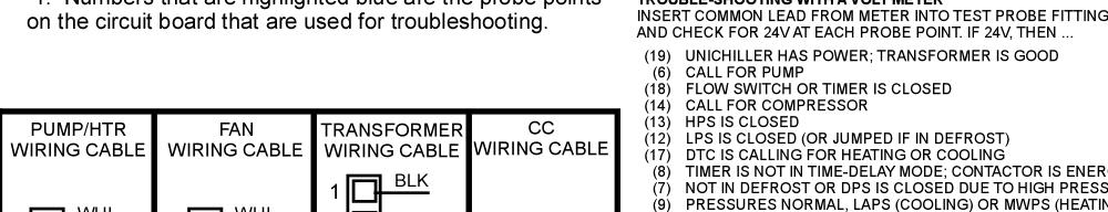
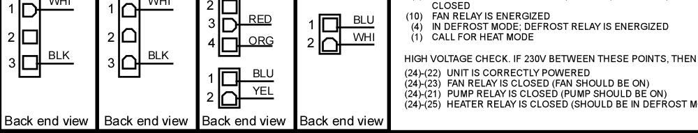
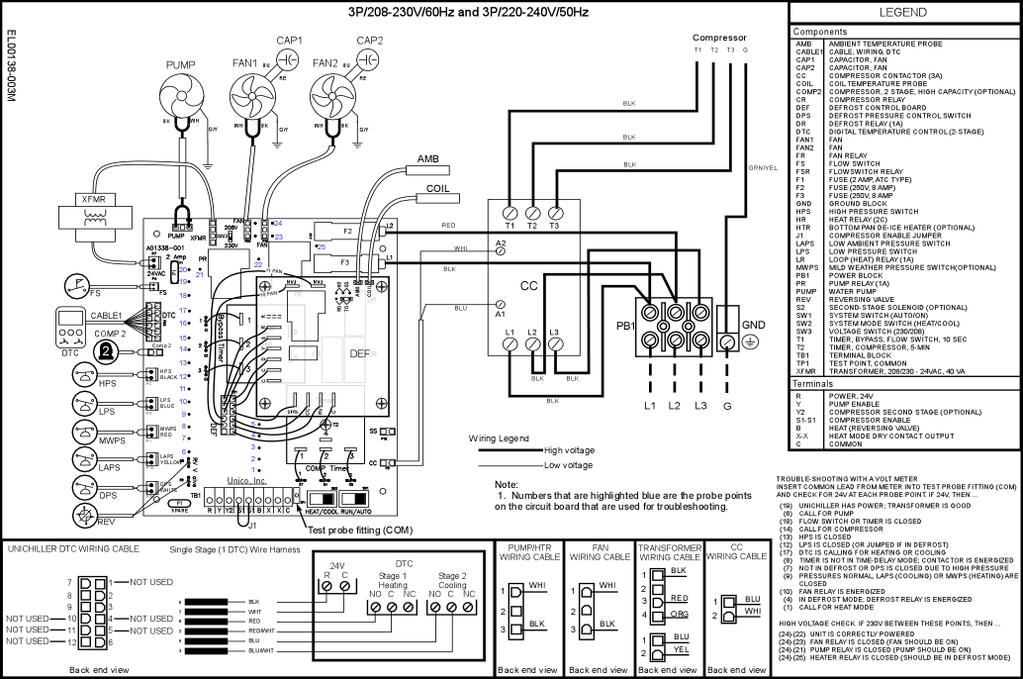
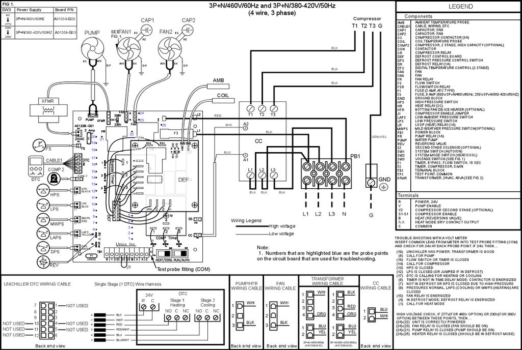
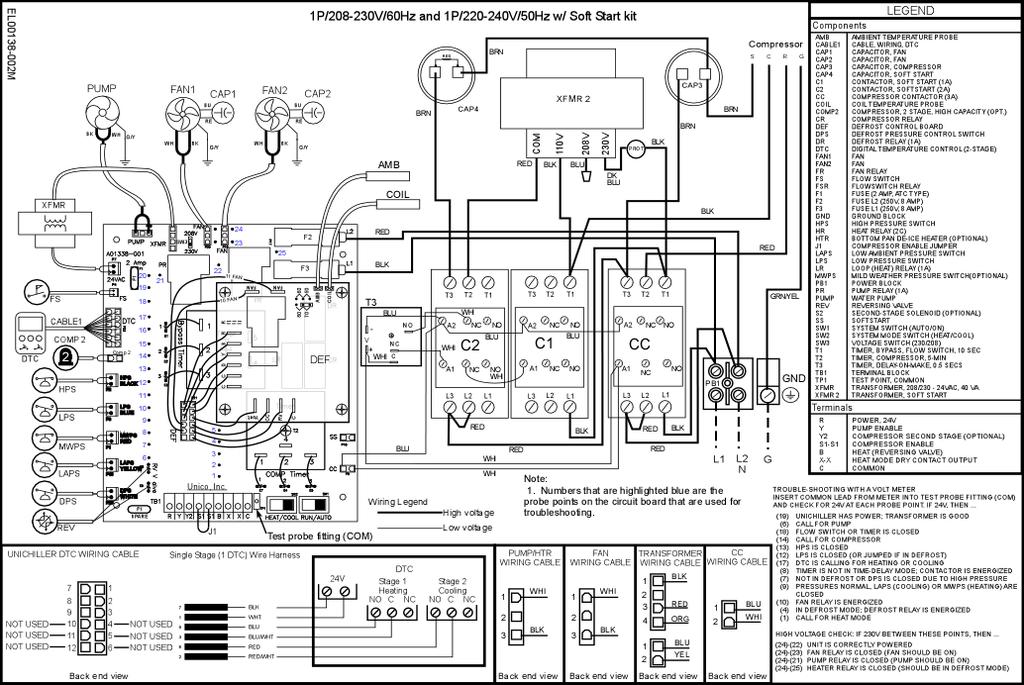
14 Troubleshooting Guide The printed circuit board has test points which can be used for trouble shooting. When trouble shooting insert the common probe of the volt meter into the COM terminal on the circuit board and probe the test points for voltage readings. Table 7 lists common trouble shooting test points and what it means when they read 24V+/ 2 volts. Socket For Common Probe From Volt Meter Figure 4. Close up of lower left Hand corner of printed circuit board showing some test pins common probe socket. Table 7. Low Voltage Test Pins at 24V AC Test Pin A reading of 24V from the test pin listed to common indicates the following: Number 19 Chiller has power; Transformer connected and good 6 External call for chiller; enable pump 18 Flow switch or timer is closed 14 External call for compressor 13 High Pressure Switch is closed 12 Low Pressure Switch is closed (or defrost relay is energized if in defrost) 17 Digital Temperature Controller Calling for Heating or Cooling 8 Timer Is Not In Time Delay Mode; Contactor Is Energized 7 Not in Defrost Or Defrost Pressure Switch (DPS) Is Closed Due To High Pressure Pressures Normal, Low Ambient Pressure Switch (if cooling) Mild Weather Pressure 9 Switch (if heating) are closed; Fan relay is energized 10 Fan Relay Is Energized 4 In Defrost Mode; Defrost relay is energized 1 External Call For Heat Mode Table 8. High Voltage Test Pins 22 and 24 Unit is correctly Powered 22 and 23 Fan Relay Is Closed (Fan Should Be On) 22 and 21 Pump Relay is Closed (Pump Relay Should be On) 22 and 26 Heater Relay Is Closed (Should Be In Defrost Mode) 11
15 The following table is to be used for troubleshooting problems that may occur with the chiller. This table should be used only if there are no modifications to the controls. Table 9a: Unichiller Troubleshooting Chart Main Problem Probable Cause Corrective Action Upon start up nothing happens Power not getting to the chiller or the control board. Check power coming into the unit. Confirm Auto/Run Switch is set to Run. Test for 230V between TP 22 and TP V for 3p/460V chillers unit is correctly powered. Check circuit board terminal block for 24 volts between R and C Board powered up. Pump does not come on. Pump does not stay on Unichiller shuts down completely (including the pump). Bypass Timer Bad Water flow restricted, defective flow switch, pump relay not closed No water in the system. Water temperature set point is too high/low. Faulty temperature controller. No Low voltage Open flow switch (Liquid solution is interrupted or air in the system). See pump troubleshooting. Put water in the system. Adjust the temperature controller set point (no lower than 38 F for cooling, no higher than 125 F for heating). Check the operation of the temperature controller. If faulty, replace. Check for 24V on transformer. Fuse on control board Check for air or debris in the system. Table 9b: Unichiller Troubleshooting Chart Compressor Problem Probable Cause Corrective Action Compressor and fan motors shut down before the set water temperature is reached. Open low pressure switch. Open Compressor time delay Bad Defrost Board Bad DTC Open high pressure switch. Check for a refrigerant leak, inoperative thermal expansion valve, low liquid solution control setting, low ambient operation, or low liquid solution flow. Check for a dirty condenser, inoperable fan motor(s), or the re circulation of condenser air. 12
16 Table 9c: Unichiller Troubleshooting Chart Pump Problem Probable Cause Corrective Action Pump shuts off shortly after the power is applied from the circuit breaker with switch turned to cool or heat position. Air in the system or lack of water in the system. Low water flow. Faulty flow switch. Table 9d: Unichiller Troubleshooting Chart Other Purge the air in the system by opening the vent plug on the pump. Install auto air vent. Check wye strainer. Check pipe sizing and operation of the pump. Flow switch will open at flow rates less than 3gpm. Check continuity of the flow switch. If faulty, replace. Problem Probable Cause Corrective Action Air in the system or lack of water in the system. Water leak. Check for cracked pipe or loose fittings. Repair, if necessary. 13
17 This Page Is Intentionally Left Blank 14
18 14
19 15
20 16
21 17
22 18
23 19
24 20
25 21
Surna 25-Ton Chiller Operating & Maintenance Manual
 www.surna.com 303.993.5271 Surna 25-Ton Chiller Operating & Maintenance Manual Models: 300F3-3. 300F4-3, 300FW-3 Revised: July 2015 Table of Contents Warranty Information 4 Limited Warranty 4 Limitation
OWNER S MANUAL. Models: AC110, AC125, AC150 made from 2003 through Proudly Made in the USA
 OWNER S MANUAL Models: AC110, AC125, AC150 made from 2003 through 2010 Proudly Made in the USA support@aquacomfort.com www.aquacomfort.com/service-and-support/ (888) 475-7443 Manufacturing High Quality,
MACH N-407 Heat Pump Air-Cooled Chiller
 MACH060-01-N-407 Heat Pump Air-Cooled Chiller Heat Pump Air-Cooled Chillers for Global Residential and Light Commercial Microclimates MACH NOMENCLATURE BREAKDOWN MACH-060-01 - N - 407 Refrigerant Type
OWNER S MANUAL. Vintage Classic HEAT COOL models. Proudly Made in the USA
 OWNER S MANUAL Vintage Classic HEAT COOL models Proudly Made in the USA support@aquacomfort.com www.aquacomfort.com/service-and-support 888-475-7443 Manufacturing High Quality, High Efficiency Heat Pump
AQUA LOGIC S MULTI-TEMP Water-Cooled Marine Duty Series chiller
 AQUA LOGIC S MULTI-TEMP Water-Cooled Marine Duty Series chiller INSTALLATION & OPERATING INSTRUCTIONS Effective 8-19-15 Thank you for purchasing an Aqua logic chiller. It has been designed and built to
Table of Contents. Page 2 of 28
 Rev. 1.1 Table of Contents Page Introduction 3 System Description 4 Electrical & Physical Data 5-6 Description of Electrical Controls 7-8 Chiller Controls Sequence of Operation 9 System Faults 10 Refrigeration
CROWN. Boiler Co. Santa-Fe Series. Hydronic Air Handlers INSTALLATION, OPERATION & MAINTENANCE INSTRUCTIONS
 CROWN Boiler Co Santa-Fe Series Hydronic Air Handlers INSTALLATION, OPERATION & MAINTENANCE INSTRUCTIONS These instructions must be affixed on or adjacent to the air handler Models: SAC049A20 SAC059A25
Prime Chiller Modular Upgradable Chiller
 Prime Chiller Modular Upgradable Chiller Instructions for Models Single Stage Thermostat #2604, 2606 Dual Stage Thermostat #2614, 2616 Single Stage Thermostat w/ TXV #2626, 2627 Warning and Safety Instructions...
Rev B, 9/2/2009. Kodiak Chiller Overview
 930-0001 Rev B, 9/2/2009 Kodiak Chiller Overview Presentation Outline Phone: 781-933-7300 Lytron Technical Support Contact Information 3 Introduction 4 Part I: Unpacking 5 Part II: Installation 7 Part
Multiaqua Chiller Manual
 Rev. 1.1 Multiaqua Chiller Manual The Multiaqua Chiller System is the only air conditioning/refrigeration system of its kind in the world today offering the degree of application flexibility described
HOMEADVANTAGE II IMPORTANT SAFETY INFORMATION
 INSTALLATION INSTRUCTIONS & HOME OWNERS MANUAL HOMEADVANTAGE II HA008240 HA011240 HA013240 HA018240 HA024240 HA027240 HA036240 IMPORTANT SAFETY INFORMATION When installing or using any high voltage electrical
SWIMMING POOL HEAT PUMP UNIT ECO - series. Installation & Instruction manual
 SWIMMING POOL HEAT PUMP UNIT ECO - series Installation & Instruction manual Rev. 1.00 28.11.2007 Contents SWIMMING POOL HEAT PUMP UNIT 1 CONTENTS 2 1. PREFACE 3 2. SPECIFICATIONS 4 2.1 Performance data
MAC N-407 Air-Cooled Chiller
 MAC036-01-N-407 Air-Cooled Chiller Air-Cooled Chillers for Global Residential and Light Commercial MicroClimates MAC036 NOMENCLATURE BREAKDOWN MAC036-01 - N - 407 Refrigerant Type Air-Cooled Chiller 036=
Operation and Maintenance Haskris LX-Series, R-Series, WW-Series, OPC-Series
 Section 1: Temperature Control Your Haskris will have one of three different types of controller. Use table 1-1 to identify the relevant controller. The controller may appear different than examples. Contact
TWLC - Tempered Water Logic Controller. The Intelligent Control
 TWLC - Tempered Water Logic Controller The Intelligent Control Chiller Controls Features: Up to six (6) stages: individual board for each stage maximizes redundancy. Menu driven access and programming.
INSTALLATION INSTRUCTIONS & HOME OWNERS MANUAL ECO 18 ECO 24 ECO 27 IMPORTANT SAFETY INFORMATION
 INSTALLATION INSTRUCTIONS & HOME OWNERS MANUAL ECO 18 ECO 24 ECO 27 IMPORTANT SAFETY INFORMATION As when installing or using any high voltage electrical appliance, basic safety precautions should always
CH750, CH751 & CH951 CHILLERS
 CH750, CH751 & CH951 CHILLERS Operator s & Installation Manual Release Date: April 19, 2002 Publication Number: 91256 Revision Date: March 25, 2014 Revision: F Visit the Cornelius web site at www.cornelius.com
SYSTEM DESIGN REQUIREMENTS
 P a g e 1 SYSTEM DESIGN REQUIREMENTS WFC-S SERIES WATER-FIRED SINGLE-EFFECT ABSORPTION CHILLERS / CHILLER-HEATERS Yazaki WFC-S Series water-fired chillers and chiller-heaters are available with nominal
CH250 AND CH251 CHILLERS
 CH250 AND CH251 CHILLERS Operator s & Installation Manual Release Date: April 19, 2004 Publication Number: 620914801 Revision Date: May 15, 2015 Revision: G Visit the Cornelius web site at www.cornelius.com
PDF Created with deskpdf PDF Writer - Trial ::
 Instruction Manual Index Introduction Uncrating and Checking for Damage Locating Your Unit Installation Fill Tank Process Connections Pre Startup Startup Sequence Trouble Shooting Chart Operating Lights
PRO SERIES IMPORTANT SAFETY INFORMATION
 INSTALLATION INSTRUCTIONS & HOME OWNERS MANUAL PRO SERIES IMPORTANT SAFETY INFORMATION When installing or using any high voltage electrical appliance, basic safety precautions should always be followed.
DUCTED AIR CONDITIONER. Owner s Manual. KD Series KD24. Kaden Owner s Manual 1
 DUCTED AIR CONDITIONER Owner s Manual KD Series KD24 Kaden Owner s Manual 1 Table of Contents 1. Safety Precautions 4 2. Indoor Unit Parts and Major Functions 6 3. Care and Maintenance 8 4. Troubleshooting
KITS COMMON TO HEATING AND COOLING EQUIPMENT 504,652M 03/04. Supersedes 503,249M
 2004 Lennox Industries Inc. Dallas, Texas KITS COMMON TO HEATING AND COOLING EQUIPMENT 504,652M 03/04 Supersedes 503,249M Litho U.S.A. COMPRESSOR REPLACEMENT KIT INSTALLATION INSTRUCTIONS FOR COMPRESSOR
Heat Pump Water Heater. Table of Contents
 Table of Contents INTRODUCTION... 3 SAFETY... 3 Electrical... 3 R410a Refrigerant... 3 Scalding... 3 Flammable Vapors... 3 COMPONENT PARTS OF THE HEAT PUMP WATER HEATER... 4 TOOLS... 10 OPERATIONAL MODES...
SWIMMING POOL & SPA HEAT PUMPS OWNERS OPERATIONAL MANUAL
 SWIMMING POOL & SPA HEAT PUMPS OWNERS OPERATIONAL MANUAL MODEL AT105 AT115 AT130 with Titanium Heat Exchanger 2213 Andrea Lane Ft. Myers FL 33912 888-297-3826 941-482-0606 www.aquathermheatpumps.com DIGITAL
Instruction manual Harmo PAC ZVWX1017/1022/1032/1041/1055/1056/1061
 Instruction manual Harmo PAC ZVWX1017/1022/1032/1041/1055/1056/1061 Imported by: Zwembad BVBA Industrieweg 9 3190 Boortmeerbeek België www.harmopool.eu 0 Table of content Introduction... 2 Safety instructions...
INSTALLATION INSTRUCTIONS AND OWNER S MANUAL FOR
 INSTALLATION INSTRUCTIONS AND OWNER S MANUAL FOR ELECTRIC ON-DEMAND TANKLESS WATER HEATERS: SpecAdvantage with PhD Technology SafeAdvantage with PhD Technology 208 and 480 VAC three phase 32 144 kw 600
Operation Manual SCT14B and SCT18B. Inspection. 3 General Description. 3 General Requirements. 3 Standard Features.
 Spot Cooling Systems, Inc. 120 Century Drive Suite 00 Carrollton, TX 7006 00-6-776 Operation Manual SCT1B and SCT1B Warning! Improper installation, adjustment, alteration, service, or maintenance can cause
π H-6621 INDUSTRIAL DEHUMIDIFIER WARNINGS SPECIFICATIONS uline.com WATER REMOVAL ELECTRICAL REQUIREMENTS BUILT-IN ELECTRICAL SAFETY
 π H-6621 INDUSTRIAL DEHUMIDIFIER 1-800-295-5510 uline.com WARNINGS Plug into a grounded 3 prong outlet. Do not remove ground prong. Do not use an adapter. Do not use an extension cord if possible. Failure
OWNER S MANUAL. Vintage Signature Series models: AC750, AC1050, AC1100, AC1250, AC1500, AC1750. Proudly Made in the USA.
 OWNER S MANUAL Vintage Signature Series models: AC750, AC1050, AC1100, AC1250, AC1500, AC1750 Proudly Made in the USA support@aquacomfort.com 888-475-7443 Manufacturing High Quality, High Efficiency Heat
Installation, Operation, and Maintenance Manual RTE14S & RTE14S-2. For the Taco Bell "Rethermalizer" Model Numbers
 Installation, Operation, and Maintenance Manual For the Taco Bell "Rethermalizer" Model Numbers RTE14S & RTE14S-2 NOTICES There are three different types of notices that you should be familiar with, a
OPERATIONS AND MAINTENANCE MANUAL FOR THE 8-TON TURF CART ENVIRONMENTAL CONTROL UNIT (ECU) PART NUMBER
 PART NUMBER") OPERATIONS AND MAINTENANCE MANUAL FOR THE 8-TON TURF CART ENVIRONMENTAL CONTROL UNIT (ECU) PART NUMBER 2001927 Prepared by: 860 Douglas Way PO Box 530 Natural Bridge Station, VA 24579 1 1.0 SCOPE: This
OPERATIONS AND MAINTENANCE MANUAL FOR THE 8-TON TURF CART ENVIRONMENTAL CONTROL UNIT (ECU) PART NUMBER 2001927 Prepared by: 860 Douglas Way PO Box 530 Natural Bridge Station, VA 24579 1 1.0 SCOPE: This
INSTALLATION AND OPERATING INSTRUCTIONS (2 Through 10-ton Air Cooled Single Stage Chillers)
") INSTALLATION AND OPERATING INSTRUCTIONS (2 Through 10-ton Air Cooled Single Stage Chillers) PORTABLE WATER CHILLERS COLD SHOT CHILLERS MARRONE & CO., INC. 14020 INTERDRIVE WEST HOUSTON, TEXAS 77032 TEL:
INSTALLATION AND OPERATING INSTRUCTIONS (2 Through 10-ton Air Cooled Single Stage Chillers) PORTABLE WATER CHILLERS COLD SHOT CHILLERS MARRONE & CO., INC. 14020 INTERDRIVE WEST HOUSTON, TEXAS 77032 TEL:
Installation Instructions
 Installation Instructions PAM3 SERIES PACKAGE AIR CONDITIONERS TABLE OF CONTENTS SAFETY LABELING AND SIGNAL WORDS... 2 UNIT DIMENSIONS... 3 SAFE INSTALLATION REQUIREMENTS... 3 LOCATING THE UNIT... 3 CLEARANCES...
CHILLERS. Operator s & Installation Manual
 CHILLERS MODELS: CH750, CH751 & CH951 Operator s & Installation Manual Release Date: April 19, 2002 Publication Number: 91256 Revision Date: May 5, 2010 Revision: D Visit the IMI Cornelius web site at
LZP-2 ZONE CONTROL PANEL
 2004 Lennox Industries Inc. Dallas, Texas, USA ZONING SYSTEM 504,926M 5/2004 Litho U.S.A. LZP-2 ZONE CONTROL PANEL INSTALLATION INSTRUCTIONS FOR ZONE CONTROL PANELS USED WITH LENNOX HEATING AND COOLING
SERVICE MANUAL FOR 6795B,C,D SERIES PACKAGED AIR CONDITIONERS
 SERVICE MANUAL FOR 6795B,C,D SERIES PACKAGED AIR CONDITIONERS TABLE OF CONTENTS 1. Warnings.................................................................. 2 2. Unit Dimensions And Specifications............................................
ENVIRONMENTAL CONTROL UNIT (ECU) PART NUMBER OPERATIONS AND MAINTENANCE MANUAL
 PART NUMBER OPERATIONS AND MAINTENANCE MANUAL") ENVIRONMENTAL CONTROL UNIT (ECU) PART NUMBER 2001829 OPERATIONS AND MAINTENANCE MANUAL Prepared by: 860 Douglas Way PO Box 530 Natural Bridge Station, VA 24579 1.0 SCOPE: This Operations and Maintenance
ENVIRONMENTAL CONTROL UNIT (ECU) PART NUMBER 2001829 OPERATIONS AND MAINTENANCE MANUAL Prepared by: 860 Douglas Way PO Box 530 Natural Bridge Station, VA 24579 1.0 SCOPE: This Operations and Maintenance
Parts Diagram. Up button. Down button. Right (fan) button. Left (system) button. RC/RH Jumper. Field programming pins
 button. Left (system) button. RC/RH Jumper. Field programming pins") Table of Contents Parts Diagram........................................................... 1 Icon Descriptions......................................................... 2 Specifications...........................................................
Table of Contents Parts Diagram........................................................... 1 Icon Descriptions......................................................... 2 Specifications...........................................................
Electrical Problems. Fuse(s) blow or circuit breaker trips. Does the unit use circuit breakers or fuses? Replace with correct fuse(s)
 blow or circuit breaker trips. Does the unit use circuit breakers or fuses? Replace with correct fuse(s)") Electrical Problems Fuse(s) blow or circuit breaker trips Does the unit use circuit breakers or fuses? Fuse(s) Circuit breakers Are the fuses dual element time delay? Is the circuit breaker HACR rated?
Electrical Problems Fuse(s) blow or circuit breaker trips Does the unit use circuit breakers or fuses? Fuse(s) Circuit breakers Are the fuses dual element time delay? Is the circuit breaker HACR rated?
EBAC MODEL WM150 INDUSTRIAL DEHUMIDIFIER OWNER S MANUAL
 EBAC MODEL WM150 INDUSTRIAL DEHUMIDIFIER OWNER S MANUAL WM150 OWNERS MANUAL Page 1 of 9 INTRODUCTION Designed for a wide range of applications, the WM150 is a rugged, industrial unit, which utilizes an
1025, BOUL. MARCEL-LAURIN INSTRUCTION MANUAL FOR WATER COOLED ENVIROCHILL CHILLER. Prepared par Claude Gadoury, P. Eng MTL TECHNOLOGIES INC.
 WYETH-AYERST CANADA INC. 1025, BOUL. MARCEL-LAURIN S T - L A U R E N T, Q U É B E C INSTRUCTION MANUAL FOR WATER COOLED ENVIROCHILL CHILLER MODEL P448800LT--55WC--22C66S Prepared par Claude Gadoury, P.
INSTALLATION AND OPERATING INSTRUCTIONS (2 Through 10-ton Air Cooled Single Stage Chillers)
") INSTALLATION AND OPERATING INSTRUCTIONS (2 Through 10-ton Air Cooled Single Stage Chillers) PORTABLE WATER CHILLERS COLD SHOT CHILLERS MARRONE & CO., INC. 14020 INTERDRIVE WEST HOUSTON, TEXAS 77032 TEL:
INSTALLATION AND OPERATING INSTRUCTIONS (2 Through 10-ton Air Cooled Single Stage Chillers) PORTABLE WATER CHILLERS COLD SHOT CHILLERS MARRONE & CO., INC. 14020 INTERDRIVE WEST HOUSTON, TEXAS 77032 TEL:
Instruction Manual for HX-DX and HX-DXHP Heat Exchangers 3 / 2017
 Instruction Manual for HX-DX and HX-DXHP Heat Exchangers 3 / 2017 Model No. HX-36DX Model No. HX-120DX Check packing slip and product to see if they match. If not, contact Aqua Logic immediately!! Important:
CHILLER. Model CH3000. Operator s & Installation Manual
 CHILLER Model CH3000 Operator s & Installation Manual Release Date: February 14, 2011 Publication Number: 620054173OPR Revision Date: May 08, 2014 Revision: B Visit the Cornelius web site at www.cornelius.com
Operator: Save these instructions for future use!
 WHITE-RODGERS 1F83-51 Non-Programmable Electronic Digital Multi-Stage Thermostat INSTALLATION AND OPERATION INSTRUCTIONS Operator: Save these instructions for future use! FAILURE TO READ AND FOLLOW ALL
MAC-120HE-03 Air-Cooled Chiller
 MAC-120HE-03 Air-Cooled Chiller 10 Ton / 120,000 BTUH Air-Cooled Chiller 380/415/460-3-50/60 1 HVAC Guide Specifications Air-Cooled Liquid Chiller Nominal Size: 10 Tons Multiaqua Model Number: MAC-120HE-03
TECHNICAL GUIDE DESCRIPTION SPLIT-SYSTEM AIR-COOLED CONDENSING UNITS MODELS: HF-07 FEATURES B-0703
 TECHNICAL GUIDE SPLIT-SYSTEM AIR-COOLED CONDENSING UNITS MODELS: HF-07 DESCRIPTION These Sunline 2000 units are completely assembled, piped and wired at the factory to provide one-piece shipment and rigging.
MODEL SCM INSTALLATION, OPERATION & MAINTENANCE MANUAL
 SCM2-0118 W30-WG0593 MODEL SCM INSTALLATION, OPERATION & MAINTENANCE MANUAL Air-To-Water Reverse Cycle Heat Pumps 3 and 5 Ton SECTION 1: READ BEFORE PROCEEDING Model SCM overview... 2 SECTION 2: SCM FIELD
INSTRUCTION MANUAL INSTALLATION OPERATION MAINTENANCE
 I.O.M. #123 updated 03/28/2016 INSTRUCTION MANUAL INSTALLATION OPERATION MAINTENANCE Covering models From 5 to 40 tons With M1 Instruments & Scroll Compressors Model: Serial Number : 525 East Stop 18 Road
Owner s Manual Refrigerated Compressed Air Dryers Model F-100
 Owner s Manual Refrigerated Compressed Air Dryers Model F-100 Read carefully before attempting to assemble, install, operate or maintain the product described. Protect yourself and others by observing
WMHP Series R410a Heat Pump INSTALLATION INSTRUCTIONS
 WMHP Series R410a Heat Pump INSTALLATION INSTRUCTIONS **WARNING TO INSTALLER, SERVICE PERSONNEL AND OWNER** Altering the product or replacing parts with non authorized factory parts voids all warranty
Swimming Pool Heat pump Instruction manual Harmo PAC series (Type ZVWX1017, ZVWX1023, ZVWX1033, ZVWX1042, ZVWX1052, ZVWX1057, ZVWX1062)
") Swimming Pool Heat pump Instruction manual Harmo PAC series (Type ZVWX1017, ZVWX1023, ZVWX1033, ZVWX1042, ZVWX1052, ZVWX1057, ZVWX1062) Imported by : Zwembad BVBA Industrieweg 9 3190 Boortmeerbeek België
Swimming Pool Heat pump Instruction manual Harmo PAC series (Type ZVWX1017, ZVWX1023, ZVWX1033, ZVWX1042, ZVWX1052, ZVWX1057, ZVWX1062) Imported by : Zwembad BVBA Industrieweg 9 3190 Boortmeerbeek België
USERS INFORMATION MANUAL
 MODULAR DX OR CHILLED WATER COOLING WITH ELECTRIC OR HOT WATER HEATING MODELS: US, UM SERIES USERS INFORMATION MANUAL For Installation In: 1. Modular Homes & Buildings 2. Residential Homes LIST OF SECTIONS
MAC120 Air-Cooled Chiller
 MAC120 Air-Cooled Chiller Air-Cooled Chillers for Global Residential and Light Commercial MicroClimates 9 MAC120 NOMENCLATURE BREAKDOWN MAC120 - XX - X - R407 10-Ton Air-Cooled Chiller Accessory Options
USER MANUAL. Portable Air Conditioner and Heater With Heat Pump Technology PAC18. Please read this manual carefully prior to operating the product.
 USER MANUAL Portable Air Conditioner and Heater With Heat Pump Technology PAC12 PAC15 PAC18 Please read this manual carefully prior to operating the product. TABLE OF CONTENTS INTRODUCTION... 3 IMPORTANT
REFRIGERATED CONDIMENT RAIL
 REFRIGERATED CONDIMENT RAIL MODEL RCR-4 Installation and Operation Instructions 2M-Z19984 Rev. - 2/13/15 RCR-4 SAFETY SYMBOL These symbols are intended to alert the user to the presence of important operating
USER S, MAINTENANCE and SERVICE INFORMATION MANUAL
 CONTENTS SAFETY INFORMATION................ 2 FOR YOUR SAFETY....................... 2 SYSTEM OPERATION.................. 2 THERMOSTATS.......................... 2 INTERMITTENT IGNITION DEVICE...........
SERVICE MANUAL FOR 6537 & 6538 SERIES TWO TON HIGH EFFICIENCY PACKAGED HEAT PUMPS
 SERVICE MANUAL FOR 6537 & 6538 SERIES TWO TON HIGH EFFICIENCY PACKAGED HEAT PUMPS TABLE OF CONTENTS 1. Warnings.................................................................. 2 2. Accessibility Of Appliance....................................................
T-Series Air Conditioner T15 Model
 INSTRUCTION MANUAL T-Series Air Conditioner T15 Model Protecting Electronics. Exceeding Expectations. McLean Cooling Technology 11611 Business Park Blvd N Champlin, MN 55316 USA Tel 763-323-8200 Fax 763-576-3200
Product Catalogue CG-PRC002E-EN. CGAD Liquid Chillers Air-Cooled Scroll Compressor 20 to 150 Tons. July Models: 50 / 60 Hz
 Product Catalogue CGAD Liquid Chillers Air-Cooled Scroll Compressor 20 to Tons Models: 50 / 60 Hz CGAD CGAD CGAD CGAD CGAD CGAD CGAD CGAD CGAD CGAD CGAD CGAD July 2012 CG-PRC002E-EN Introduction IMPORTANT:
PACKAGED AIR COOLED Product Data Catalog
 PACKAGED AIR COOLED Product Data Catalog MODELS ASP-10A ASP-15A ASP-20A ASP-00P ASP-00F ASP-00G A MEMBER OF MARDUK HOLDING COMPANY, LLC The Leader in Modular Chillers ETL and CSA Approved CHILLER MODULES
USER S, MAINTENANCE and SERVICE INFORMATION MANUAL
 CONTENTS SAFETY INFORMATION................ 2 FOR YOUR SAFETY...................... 2 SYSTEM OPERATION.................. 2 THERMOSTATS.......................... 2 INTERMITTENT IGNITION DEVICE..........
TCA-9102 Series Surface Mount Temperature Controllers with High and Low Alarm
 TCA-9102 Series Surface Mount Temperature Controllers with High and Low Alarm General Description & Applications The TCA-9102 Series Temperature Controller with Alarm offers a versatile solution for a
MARINE FAN COILS INSTALLATION MANUAL
 MARINE FAN COILS INSTALLATION MANUAL MARINE CHILLED WATER FAN COILS INSTALLATION MANUAL Models : CFPG05 CFPG09 CFPG12 CFPG16 CFPG24 INTRODUCTION 3 SAFETY PRECAUTIONS TECHNICAL PARAMETERS INSTALLATION OVERVIEW
TITAN SERIES Complete Central Chiller & Pump Tank Package 20 to 70 Tons 20 F to 70 F
 Temperature Control Units Water & Oil - F Portable Chillers Air & Water-Cooled - 7 F Central Chillers Air & Water-Cooled Packages & Modules - 7 F Pump Tank Stations Chilled or Tower Water - gallons Cooling
Glass Door Refrigerators
 To better help you obtain assistance or service should you ever need it, write down the following information about the product. This information is on the identification label located on the left hand
USER S MANUAL AND INSTALLATION INSTRUCTIONS IMPORTANT
 USER S MANUAL AND INSTALLATION INSTRUCTIONS P3BD Series 13 SEER Single Package Air Conditioner IMPORTANT Read this owner information to become familiar with the capabilities and use of your appliance.
Contents. Specifications. Description SV HP 55 SV HP 90. Specifications Warnings Introduction Overview... 4
 Contents Specifications Specifications... 1 Warnings... 2 Introduction... 3 Overview... 4 Installation Instructions... 5 Cable Connections... 6 Plumbing Diagram... 7 Electrical Wiring Diagram... 8 SV System
Quick Start Guide. For product manuals and further installation / operation procedures visit
 Quick Start Guide For product manuals and further installation / operation procedures visit www.aquacal.com Important Read This Guide Before Installing or Operating Heat Pump LTP0093 Rev 1 03/21/2014 Page
Condensing Unit Installation and Operating Instructions
 Bulletin WCU_O&I 01 June 2003 Condensing Unit Installation and Operating Instructions WCU Air Cooled Condensing Unit Table of Contents Section 1. Section 2. Section 3. Section 4. Section 5. Section 6.
UNDERCOUNTER LABORATORY REFRIGERATORS and FREEZERS Installation, Operation and Maintenance Instructions
 UNDERCOUNTER LABORATORY REFRIGERATORS and FREEZERS Installation, Operation and Maintenance Instructions INSPECTION When the equipment is received, all items should be carefully checked against the bill
OWNERS MANUAL YEAR LIMITED WARRANTY READ ALL INSTRUCTIONS BEFORE PROCEEDING. Store this booklet for future reference
 3100 Premier Series Non-Programmable 2 Heat / 2Cool & Heat / Cool Digital Thermostat OWNERS MANUAL Compatible with low voltage multi-stage heat / cool systems with up to two stages of heating and two stages
IMPORTANT SAFETY INSTRUCTIONS READ AND FOLLOW ALL INSTRUCTIONS SAVE THESE INSTRUCTIONS. Table of Contents WARNING.
 Eagle Pump Owners Manual IMPORTANT SAFETY INSTRUCTIONS READ AND FOLLOW ALL INSTRUCTIONS SAVE THESE INSTRUCTIONS Table of Contents SECTION I. INSTALLATION... 2 SECTION II. OPERATION & MAINTENANCE... 2 SECTION
Owner s Manual PRINTED IN CANADA 05/2009
 Owner s Manual PRINTED IN CANADA 05/2009 Table of contents Introduction 2 General Safety Instructions 4 Installation Instructions Location 6 Water piping 7 Electrical 7 Bonding 8 Bonding and plumbing
EBAC MODEL CD30 INDUSTRIAL DEHUMIDIFIER OWNER S MANUAL
 EBAC MODEL CD30 INDUSTRIAL DEHUMIDIFIER OWNER S MANUAL Ebac Industrial Products 704 Middle Ground Boulevard Newport News, VA 23606 Tel: 757 873 6800 Fax: 757 873 3632 Website: www.ebacusa.com UNPACKING
INSTRUCTION MANUAL Portable Refrigerator Units MODEL 15-LITER Including the Standard Battery Backup System (BBS)
") 1 INSTRUCTION MANUAL Portable Refrigerator Units MODEL 15-LITER Including the Standard Battery Backup System (BBS) SECTION TITLE PAGES 1 Introduction and Basic Operation 2-3 2 Cleaning & Storing 4 3 Basic
1 INSTRUCTION MANUAL Portable Refrigerator Units MODEL 15-LITER Including the Standard Battery Backup System (BBS) SECTION TITLE PAGES 1 Introduction and Basic Operation 2-3 2 Cleaning & Storing 4 3 Basic
EARTHLINKED GEOTHERMAL RENEWABLE ENERGY SYSTEMS MAINTENANCE GUIDE
 EARTHLINKED GEOTHERMAL RENEWABLE ENERGY SYSTEMS MAINTENANCE GUIDE This guide is directed at EarthLinked trained and authorized technicians servicing and maintaining the system and should be left with the
DOM MODEL SERIAL NUMBER VOLTAGE/HERTZ/PHASE
 DOM MODEL SERIAL NUMBER VOLTAGE/HERTZ/PHASE DON T JUST DO IT! Make sure the chiller you buy has been ETL listed as a complete unit. Intertek Testing Services, testing is your only assurance that your chiller
HP727S. Single speed swimming pool heat pump controller Operation manual TABLE OF CONTENTS
 HP727S Single speed swimming pool heat pump controller Operation manual TABLE OF CONTENTS 1. General Description 2. Specifications 3. Installation Instructions 4. Electrical Wiring 5. Instrument Wiring
Tempered Water Logic Control OPERATION l TROUBLE SHOOTING
 Tempered Water Logic Control OPERATION l TROUBLE SHOOTING English For MPE Multiple Chiller Units Control Panel TEMPERED WATER SYSTEMS L-2199 Rev. 20080223 Revision: L-2199 20101104 *** IMPORTANT NOTICE
347002K/177002K/34900
 Service Manual Models: 347002K/177002K 34900/347012K Manifold Block Style Recovery/Recycling/Recharging Unit For R-12 or R-134a Only TABLE OF CONTENTS: Theory of Operation and Safety Precautions... 2 Depressurizing
Owner s Manual. Middle Static Pressure Duct Type MEU-18MPH2 MEU-24MPH2 MEU-36MPL2 MEU-48MPL2 MIDDLE STATIC PRESSURE DUCT TYPE AIR CONDITIONER
 MIDDLE STATIC PRESSURE DUCT TYPE AIR CONDITIONER Owner s Manual Middle Static Pressure Duct Type MEU-18MPH2 MEU-24MPH2 MEU-36MPL2 MEU-48MPL2 IMPORTANT NOTE: Read this manual carefully before installing
INSTRUCTION MANUAL INSTALLATION OPERATION MAINTENANCE
 I.O.M. #075 updated 11/01/2016 INSTRUCTION MANUAL INSTALLATION OPERATION MAINTENANCE Covering models From 5 to 40 tons With CF Instruments & Scroll Compressors Model: Serial Number : 525 East Stop 18 Road
SC Installation, Operation & Application Guide
 SC 5211 2-Stage Heat Pump Auto Changeover Hardwire Programmable Electronic Thermostat 7-Day, 5-2-Day or 5-1-1-Day Programmable Configurable 2-Stage Heat Pump Systems Large Display With Backlight Selectable
SMART. 4,9 49,5 kw. Air cooled liquid chillers and heat pumps equipped with scroll compressor and axial fans T_SMT_0609_GB
 T_SMT_0609_GB 4,9 49,5 kw Air cooled liquid chillers and heat pumps equipped with scroll compressor and axial fans INDEX SERIES IDENTIFICATION... 3 MODEL IDENTIFICATION... 3 CE CONFORMITY... 3 WORKING
INSTALLATION INSTRUCTIONS
 INSTALLATION INSTRUCTIONS T CLASS TPA Series HEAT PUMPS 7.5 TO 10 TONS 506148 01 12/08 Litho U.S.A. RETAIN THESE INSTRUCTIONS FOR FUTURE REFERENCE IMPORTANT The Clean Air Act of 1990 bans the intentional
HT-2 / 9600 Series Control Contents
 HT-2 / 9600 Series Control Contents Tools & Parts Tools Required Parts Required Error Messages 3 Flashing Dots Pressure or Flow Switch Not Activated Pressure or Flow Switch Activated Temperature Sensor
INSTALLATION AND OPERATING INSTRUCTIONS
 INSTALLATION AND OPERATING INSTRUCTIONS HIGH-EFFICIENCY CONDENSING UNITS RAWD- 6 1 2 & 7 1 2 TON RAWE - 6 1 2 & 7 1 2 TON! RECOGNIZE THIS SYMBOL AS AN INDICATION OF IMPORTANT SAFETY INFORMATION!! WARNING
EEMAX ProAdvantage Series 1
 EEMAX ProAdvantage Series 1 ELECTRIC INSTANTANEOUS WATER HEATER INSTALLATION GUIDE AND OWNER S MANUAL MODELS COVERED: PA004120T 1Φ 120V PA008208T 1Φ 208V PA005240T 1Φ 240V PA007240T 1Φ 240V PA010240T 1Φ
WARNING Important Safety Information
 1 Specifications Premier Series Non-Programmable Thermostats MODEL 3000 MODEL 3200 1 2 3 4 5 Specifications Installation Testing Your New Thermostat Programming User Settings Temperature Adjustment WARNING
Owner s Manual Refrigerated Compressed Air Dryers Models F-3528, F-3529, F-3530, F-3531 & F-3532
 Owner s Manual Refrigerated Compressed Air Dryers Models F-3528, F-3529, F-3530, F-3531 & F-3532 Read carefully before attempting to assemble, install, operate or maintain the product described. Protect
QUICK REFERENCE GUIDE P.C. BOARD/WALL THERMOSTAT FOR 6536A891, 6536B891 & 6536C891 TWO TON PACKAGED HEAT PUMPS
 QUICK REFERENCE GUIDE P.C. BOARD/WALL THERMOSTAT FOR 6536A891, 6536B891 & 6536C891 TWO TON PACKAGED HEAT PUMPS Note: This manual may also be used for 6536-871 series heat pumps if the 6535-3209 Replacement
EEMAX HOME ADVANTAGE
 EEMAX HOME ADVANTAGE ELECTRIC INSTANTANEOUS WATER HEATER INSTALLATION GUIDE AND OWNERS MANUAL MODELS COVERED:- SS015240TC 208-240V SS019240TC 208-240V READ THE GENERAL SAFETY SECTION BEGINNING ON THE INSIDE
Owner s Manual Super-Slim Four-Way Cassette
 CASSETTE- TYPE AIR CONDITIONER Owner s Manual Super-Slim Four-Way Cassette IMPORTANT NOTE: Read this manual carefully before installing or operating your new air conditioning unit. Make sure to save this
Table of Contents. Service Procedures. Service Procedures. Measuring Superheat (4) Measuring Subcooling (5) Airflow Calculation (6-8)
 Measuring Subcooling (5) Airflow Calculation (6-8)") Table of Contents Refrigeration Cycle Service Procedures Measuring Superheat (4) Measuring Subcooling (5) Airflow Calculation (6-8) Solving Problems Identifying Low System Charge (9-11) Identifying High
Table of Contents Refrigeration Cycle Service Procedures Measuring Superheat (4) Measuring Subcooling (5) Airflow Calculation (6-8) Solving Problems Identifying Low System Charge (9-11) Identifying High
INSTALLATION INSTRUCTIONS AND OWNER S MANUAL
 INSTALLATION INSTRUCTIONS AND OWNER S MANUAL ELECTRIC INSTANTANEOUS WATER HEATERS WITH PhD 208 and 480 VAC three phase 32 144 kw 600 VAC three phase 130 / 150 kw BEFORE ATTEMPTING ANY INSTALLATION OR SERVICE
INSTALLATION & OPERATION MANUAL
 DC INVERTER AIR TO WATER HEAT PUMP AC series Heating & Cooling series CX30 INSTALLATION & OPERATION MANUAL Version 1.5 1 Table of Contents Safety Precautions... 3 Components... 4 Hydronic piping and design
CHGV AIR COOLED WATER CHILLER WITH HYDRAULIC EQUIPMENT AIR / WATER 21 to 39 kw
 TECHNICAL INSTRUCTIONS CHGV AIR COOLED WATER CHILLER WITH HYDRAULIC EQUIPMENT AIR / WATER 21 to 39 kw CHGV 22 CHGV 2 CHGV 32 CHGV 40 PHRV heat pump model also available September 2007 10 12 11 - GB - 02
CHGV AIR COOLED WATER CHILLER WITH HYDRAULIC EQUIPMENT AIR / WATER 47 to 78 kw
 TECHNICAL INSTRUCTIONS CHGV AIR COOLED WATER CHILLER WITH HYDRAULIC EQUIPMENT AIR / WATER 47 to 78 kw CHGV 50 CHGV 64 CHGV 72 CHGV 80 PHRV heat pump model also available November 2007 10 12 167 - GB -