Record of System Specifications 2 Product Dimensions 3 Pre-Installation Checklist 4 System Installation 5-9 Installation Notice, Unit location,
|
|
|
- Alice Howard
- 6 years ago
- Views:
Transcription
1
2 Record of System Specifications 2 Product Dimensions 3 Pre-Installation Checklist 4 System Installation 5-9 Installation Notice, Unit location, Plumbing Setup, Control Valve Installation Instructions 5 System Sizing, Bypass Installation Instructions 6 Plumbing Connections, Drain Line Installation, Brine Line Installation 7 Brine Tank Installation 8 System Installation Chart 9 HD Valve Programming Sanitizing Procedure 15 Water Flow Diagram Assembly Drawings and Parts List HD-SMM & HD-FTC Valve Drive Assembly and Parts List HD Valve Body Assembly and Parts List Meter Assembly, Parts List, & Wiring Diagram 25 Bypass and Bypass Mixing Valve Assembly Service Instructions Replacing Brine Valve, Injectors, and Screen 28 Replacing Timer 29 Replacing Piston Assembly 30 Replacing Seals and Spacers 31 Replacing Meter 32 Replacing Meter Cover and Impeller 33 Trouble Shooting Softener System Trouble Shooting Filter System Trouble Shooting 37 Warranty 38 Contact Information 39
3 Fill in the content below for future reference. Installer Name: Address: City/State: Phone: Install Date: Softener System Configuration Tank Size: Dia. in Height in Resin Volume: cu/ft. Brine Tank Capacity: 85L 100L 130L Media: Control Valve Serial Number: (label located on valve body front) Valve Style: HD-FTC HD-SMM Day/Time of Regeneration: Drain Line Flow Control (DLFC): gpm Brine Line Flow Control (BLFC): gpm Injector Size: Salt Setting: Meter Gallon Setting: gal Water Conditions and Quality Total Hardness: grains Iron (Fe): ppm Acid (ph): TDS: ppm Pressure of Inlet Water: PSI Other: Water Source: Well Water City Water Other:
4 HD-SMM Standard Digital Meter Control Valve Dimensions Product Dimensions - HD Control Valves Length(max) Width(max) Height (max) Regeneration Mode Down-flow Inlet Port Outlet Port Drain Port Brine Port Base Riser Pipe 3/4 3/4 1/2 NPTF 3/8 2.5 NPSM 1.05 The valve dimensions are for reference only. Plumbing Rough-ins - HD Control Valves Bypass Tank center to end of bypass Inlet/Outlet Center Inlet/Outlet Height 9x48 Tank Inlet/Outlet Height 10x44 Tank Inlet/Outlet Height 10x54 Tank Inlet/Outlet Height 12x52 Tank Inlet/Outlet Height 13x54 Tank 1 Metal Bypass 5-3/ /8 56-3/4 54-7/8 56-7/8 ¾ Metal Bypass 5-1/ /8 56-3/4 54-7/8 56-7/8 Plastic Bypass 6-3/ /8 56-3/4 54-7/8 56-7/8 The dimensions are for reference only.
5 Before installation, read through this manual thoroughly. Then obtain all materials and tools needed for installation. This softening system will operate at maximum efficiency when the following conditions are considered. Required Operating Conditions: Working Conditions Working Environment Working Pressure 25psi~120psi Water Temperature 40 F~100 F Environment Temperature 40 F~100 F Relative Humidity 95% Power Source AC100~240V/50~60Hz All plumbing and electrical work should be performed by an accredited professional to ensure all local, state, and municipal guidelines are met. An uninterrupted alternating current (A/C) supply is required. Please make sure voltage supply is compatible with unit before installation. Conditions of existing plumbing should not be clogged with lime or iron build-up. Replace piping that has heavy lime and/or iron build-up. If there is an iron concern, install an iron filter unit ahead of the water softener. Plumbing that has heavy lime and iron buildup inhibits the operation of softening system. When there is moderate to high turbidity, a filter should be installed on the inlet before the water softening system. If the water pressure exceeds 120psi, a pressure reducing valve must be installed before the water inlet. If the water pressure exceeds 80 psi, installing a pressure reducing valve before the water inlet is highly recommended. If the water pressure is under 25psi, a booster pump must be installed before the water inlet. Ensure there is salt in the brine tank at all times when this valve is used for softening. The brine tank should contain clean water and softening salt only, at least 99.5% pure. Do not use small grain salt. Always install a bypass valve. Replacement parts for the valve should only be purchased through Hankscraft H20 Products resellers. Regular interval monitoring of the water quality and work environment is recommended to insure proper operation of the valve and system. CAUTION Do not exceed 120 psi water pressure. Do not exceed 40 C / 100 F water temperature. Do not subject unit to freezing conditions. ***Failure to use this product within the described conditions may void the warranty***
6 Installation Notice Before installation, read through this manual thoroughly and obtain all materials and tools needed for installation. All plumbing and electrical work should be performed by an accredited professional to ensure all local, state, and municipal guidelines are met. During cold weather it is recommended that the installer warm the valve to room temperature before operating. Unit Location Locate the filter or softener close to a clean working floor drain away from direct sunlight and any heat sources. This will minimize consumer impact in the event of malfunction. Ensure the unit is installed with enough space for operation and maintenance. The installation surface should be clean, level and stable for both the pressure tank and brine tank. Plumbing and Mechanical Setup 1. Complete all plumbing according to local, state, and federal plumbing codes. a. A ½ (13mm) minimum drain pipe should be used. However, if the backwash flow rates exceed 7gpm or the length exceeds 20 feet (6m) then a ¾ (19mm) drain pipe should be used. b. There must be an air gap between the drain line and the drain to prevent siphoning of contaminated water back into the resin tank. 2. Use only Teflon tape on the drain fitting. 3. Solder joints should be completed prior to connecting piping to the valve. Solder joints near the drain must be done before connecting the Drain Line Flow Control fitting (DLFC). Leave at least 6 (152mm) between the DLFC and solder joints when soldering pipes that are connected on the DLFC. Failure to do this could cause interior damage to valve. The valve manufacturer is not responsible for damage incurred during installation. 4. When turning threaded pipe fittings onto plastic fitting, take precaution not to cross thread or over tighten. Control Valve Installation 1. Cut the 1 (25mm) distributor tube (1.050 O.D.) flush with the top of the tank. Take care to keep foreign material out of mineral tank. If purchased as a complete system, the tube has already been cut and installed. 2. Insert distributor tube with lower basket into the center of the pressure tank. 3. Plug the riser pipe and fill the pressure tank with resin. If purchased as a complete system from Hankscraft H2O Products the media has been installed. Media quantity is relative to desired capacity and tank size. 4. Lubricate the valve center hub O-ring with silicone lubricant only. 5. Install the upper basket with a twist and lock action to center hub of the valve. 6. Lubricate, with silicone lubricant, and install the valve base O-ring around the neck of the valve. 7. Place valve on tank with the distributor tube inserted down the middle of the upper basket. Twist the valve on to the tank to secure valve to tank.
7 System Sizing Chart Tank Size Injector Slow 40 psi Brine 40 psi ¹ BLFC ²DLFC 9 #1 White.45 gpm.28 gpm.25 gpm 2.0 gpm 10 #1 White.45 gpm.38 gpm.5 gpm 2.4 gpm 12 #2 Blue.84 gpm.56 gpm 1.0 gpm 3.5 gpm 13 #2 Blue.84 gpm.56 gpm 1.0 gpm 4.0 gpm 14 #4 Green 1.0 gpm.63 gpm 1.0 gpm 5.0 gpm 16 #4 Green 1.0 gpm.63 gpm 1.0 gpm 7.0 gpm Note: Due to varying water conditions, tank sizes, and water pressures, use the above settings as guidelines only. ¹BLFC (Brine Line Flow Control), refill rate for filling brine tank. ²DLFC (Drain Line Flow Control), backwash and rapid rinse flow rates. Bypass Installation Plastic Bypass 1606P Grease bypass O-rings and press onto valve. Secure with clips. Grease and install spools into the bypass. Attach yoke to bypass. Stainless Steel Bypass 1606K/1606KB Grease bypass O-rings and press onto valve. Secure with clips. Before running the valve for the first time, flush out the water line and bypass. 1. Be sure the bypass is closed. 2. Turn the water source on at the inlet to the house. 3. Disconnect the bypass from the valve. 4. Put a container under the bypass and open the bypass to remove any foreign material out of the water lines. 5. Close the bypass. 6. Re-connect the bypass to the valve. 7. Open the bypass slowly, to avoid water hammering. 8. Let water flow into the pressure tank. When water flow stops, slowly open a cold water tap nearby and let water run until it runs clear and air is purged from the unit. Then close tap. 9. Check for and repair any leaks. 10. Start-up procedures are shown on the following pages for each different valve type. Locate your valve type and follow the start-up procedures listed.


8 Plumbing Connections As figure shows, 1. Connect inlet pipe with inlet connector of bypass. 2. Connect outlet pipe with outlet connector of bypass. Drain Line Installation As figure shows, 1. Install drain line with an air gap to the floor drain. Valve drain hose not supplied. An air gap is required between the drain line and the drain (sewer). This avoids a syphon effect and reverse contamination. Brine Line Installation As figure shows, 1. Slide brine nut onto the 3/8 brine tubing. 2. Install the filter screen into the ferrule and insert the ferrule into the end of brine tube. 3. Insert tube into brine connector and secure brine nut to the brine connector.


9 Brine Tank Installation 1. Remove cap from brine well. Remove overflow nut and float from the well. 2. Adjust the float to the desired salt line. Use a twist and pull action to slide upper rubber stopper to desired position. Note: Hold float rod securely to not pull from air check assembly. Repeat with lower rubber stopper to secure float in position. Refer to Figure 3 9x48 to white tape or above 10x44 to blue tape or above 10x54 to blue tape or above 12x52 to green tape or above 3. Secure brine well to brine tank with the overflow elbow and nut using the lower hole. Refer to Figure 1 4. Replace brine float into brine well. 5. Insert brine line tubing through the upper hole of tank and well. Refer to Figure 2 6. Slide brine line nut onto brine line, insert line into well, and secure nut to well. 7. Replace brine well cap. 8. Attach a drain tube to the overflow elbow. Maintain an air gap between the tube and floor drain. 9. Place approximately 1 (25mm) of water above the grid plate. If a grid is not utilized, fill to the top of the air check in the brine well. Note: Do not add salt to the brine tank at this time. Figure 1 Figure 2 Figure 3
10 System Installation Chart

11 HD Standard Digital Meter Control Valve Programming, Installation, and Start-up Procedures Time of Day Day of Week Water Treatment Capacity Up Button Right Button Setting Button Setting Button 1. Press for 5 seconds to enter Programming Mode. 2. When the valve is in Programming Mode, Press to confirm the setting and enter into next menu. Right Button 1. Press for 5 seconds to start immediate manual regeneration. 2. Press during a Regeneration Cycle to immediately advance the valve to the next cycle position. 3. When the valve is in Programming Mode, press to move the cursor. Up Button 1. Press for 5 seconds to display existing configured parameters. 2. When the valve is in Programming Mode, press to adjust settings.


12 HD Standard Digital Meter Control Valve Factory Default Settings Parameter Unit Default Control Type Meter Delayed Time of Day 24 Hour Clock 08:00am Day of Week Sunday Days Override Days 30 Time of Regeneration 24 Hour Clock 2:00 Unit Mode Gallons/Liters Gallons Feed Water Hardness Grains 10 Number of People 4 Reference Setting On or Off On Water Treatment Capacity Grains 32,000 grains Backwash Time Minutes 10 Brine Draw Time Minutes 60 Rapid Rinse Time Minutes 10 Water Refill Time Minutes 12 To reset valve to factory settings valve must be unplugged. Press and hold while plugging valve back in. The valve is now restored to factory settings. Programming the Control Valve 1. Time of Day/Day of Week Press and hold (setting button) for 5 seconds to enter the Programming Mode. Set the Time of Day and Day of Week. Use the to adjust the hour. Press to move to the minute, adjust using the. Press to move to the day and adjust using the. Press to accept and advance to next screen. 2. Control Type Use the to select Control Type. TC-Time Clock, MD-Meter Delayed, MI-Meter Immediate, or DW-Day(s) of Week. Meter Delayed is set as the default. Press Time Clock Meter Delayed Meter Immediate Day(s) of Week to accept and advance to next screen.


13 3. Unit Mode - Gallon or Liter Gallon is set as the default. If you want to change to Liter, press. Press to accept and advance to next screen. 4. Feed Water Hardness 10 grains hardness is set as the default. To change the Hardness, press until desired hardness is reached. The hardness range is 1-50 grains. Press to accept and advance to next screen. Note: To convert ppm hardness to grains hardness divide by 17.1; this will give you water hardness in grains. 5. Number of People 4 people is set as the default. To change the number of people, press until correct number of people in home is reached. People range is 1-10 people. Press 6. Reference - On or Off to accept and advance to next screen. Reference On will calculate the capacity automatically based on system size. Reference Off allows you to set the capacity manually. Default is set as Reference On. To change the Reference, press. Press to accept and advance to next screen. Note: Reference settings change to the correct cycle times, however, the BLFC, DLFC, throat and nozzles will need to be changed for the systems larger than 32,000. Refer to the sizing chart on page Water Treatment Capacity (Reference On) Reference On Capacity default is set at 32K. To change the system capacity, press until desired capacity is reached. 32,000 grains (32K), 40,000 grains (40K), 48,000 grains (48K), 64,000 grains (64K) Press to accept and advance to next screen. Reference Backwash (BW) Brine Slow Rinse (BSR) Fast Rinse (FR) Brine Refill (BR) 32K 10 minutes 60 minutes 10 minutes 12 minutes 40K 10 minutes 60 minutes 10 minutes 14 minutes 48K 10 minutes 60 minutes 10 minutes 8 minutes 64K 10 minutes 60 minutes 10 minutes 10 minutes


.")


14 8. Water Treatment Capacity (Reference Off) User-Defined Capacity default is set at 32,000. Turning the reference off allows you to manually adjust the system capacity. Press until desired capacity is reached. Range 8,000-99,999 grains. Press to accept and advance to next screen. You will now be able to manually adjust each cycle time. 9. Day Override Day Override default is set at 30 days. To change the number of days, press the desired number of days is reached. Range is 1-99 days/off Press to accept and advance to next screen. until 10. Day of Week to Regenerate Used only when DW-Day(s) of Week Control Type is selected. There are 7 days. Use the to select day and the to move to the next day. Repeat until the desired schedule is reached. Press to accept and advance to next screen. 11. Regeneration Time Default is set for 2:00am (24 hour clock). To change the time of regeneration, press until the desired time of regeneration is reached. Press to accept and advance to next screen. 12. Regeneration Cycle Times Note: The cycle times are adjustable only when the reference setting has been turned off. When the reference setting is on, the times are automatically set for you. Defaults: Backwash-10 min Brine Slow Rinse-1hour Fast Rinse-10 min Brine Refill-12 min HD-FTC Reference Chart Sand Filter Sediment Turbidity Mild Average Extreme Activated Carbon Filters Taste and Odor Mild Average Extreme Iron Filters PPM Ironx1 PPM Manganesex1 PPM Sulfurx1 No. Of People Calendar Clock Regeneration Frequency Number Of Tab Pulls Filter Timer Regeneration Reference Chart
15 Capacity Reference Chart Hardness PPM (GPG) Hardness PPM (GPG) Capacity 18,000 Capacity 36,000 85(5) 171(10) 256(15) 342(20) 513(30) 684(40) 855(50) 85(5) 171(10) 256(15) 342(20) 513(30) 684(40) 855(50) 1 2,100 1,725 1, ,100 2,100 2,100 1,725 1, ,100 1,650 1, ,100 2,100 2,100 1,650 1, No. of 3 2,100 1, No. of 3 2,100 2,100 2,100 1, People 4 2,100 1, People 4 2,100 2,100 2,100 1, ,100 1, ,100 2,100 2,025 1, ,100 1, ,100 2,100 1,950 1, Hardness PPM (GPG) Hardness PPM (GPG) Capacity 24,000 Capacity 40,000 85(5) 171(10) 256(15) 342(20) 513(30) 684(40) 855(50) 85(5) 171(10) 256(15) 342(20) 513(30) 684(40) 855(50) 1 2,100 2,100 1,525 1, ,100 2,100 1,925 1, ,100 2,100 1,450 1, ,100 2,100 1,850 1, No. of 3 2,100 2,100 1, No. of 3 2,100 2,100 1,775 1, People 4 2,100 2,100 1, People 4 2,100 2,100 1,700 1, ,100 2,025 1, ,100 2,100 1,625 1, ,100 1,950 1, ,100 2,100 1,550 1, Hardness PPM (GPG) Hardness PPM (GPG) Capacity 30,000 Capacity 48,000 85(5) 171(10) 256(15) 342(20) 513(30) 684(40) 855(50) 85(5) 171(10) 256(15) 342(20) 513(30) 684(40) 855(50) 1 2,100 2,100 1,925 1, ,100 2,100 2,100 1,725 1, ,100 2,100 1,850 1, ,100 2,100 2,100 1,650 1, No. of 3 2,100 2,100 1,775 1, No. of 3 2,100 2,100 2,100 1, People 4 2,100 2,100 1,700 1, People 4 2,100 2,100 2,100 1, ,100 2,100 1,625 1, ,100 2,100 2,025 1, ,100 2,100 1,550 1, ,100 2,100 1,950 1, Hardness PPM (GPG) Hardness PPM (GPG) Capacity 32,000 Capacity 64,000 85(5) 171(10) 256(15) 342(20) 513(30) 684(40) 855(50) 85(5) 171(10) 256(15) 342(20) 513(30) 684(40) 855(50) 1 2,100 2,100 1,525 1, ,100 2,100 2,100 2,100 1,525 1, ,100 2,100 1, ,100 2,100 2,100 2,100 1,450 1, No. of 3 2,100 2,100 1, No. of 3 2,100 2,100 2,100 2,100 1, People 4 2,100 2,100 1, People 4 2,100 2,100 2,100 2,100 1, ,100 2,025 1, ,100 2,100 2,100 2,025 1, ,100 1,950 1, ,100 2,100 2,100 1,950 1,
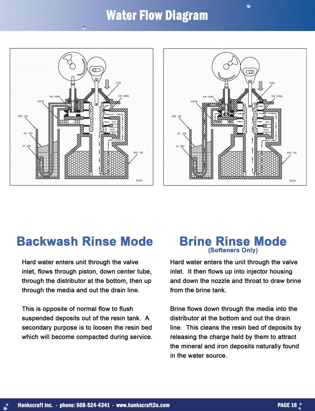
16 Sanitizing Procedure At the start up or after a period of one week the following procedure is recommended to remove the possibility of bacterial growth or contamination within the system. This procedure relates only to the original description of equipment and options described for this system. Any alterations to the configuration would require evaluation by a trained water professional. Remove the brine tank cover and locate the brine well. Remove the brine well cap. Pour 1/3 cup of unscented bleach into the brine well. Place cap back on brine well and cover back on brine tank. The system must now be regenerated. At the control valve turn the knob clockwise until the indicator shows Regen. Allow approximately 2 hours for the valve to complete its regeneration cycle and to return to service mode.
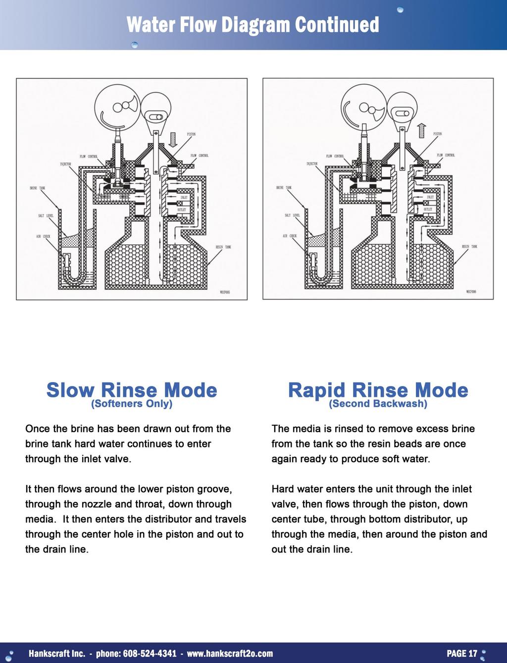
17
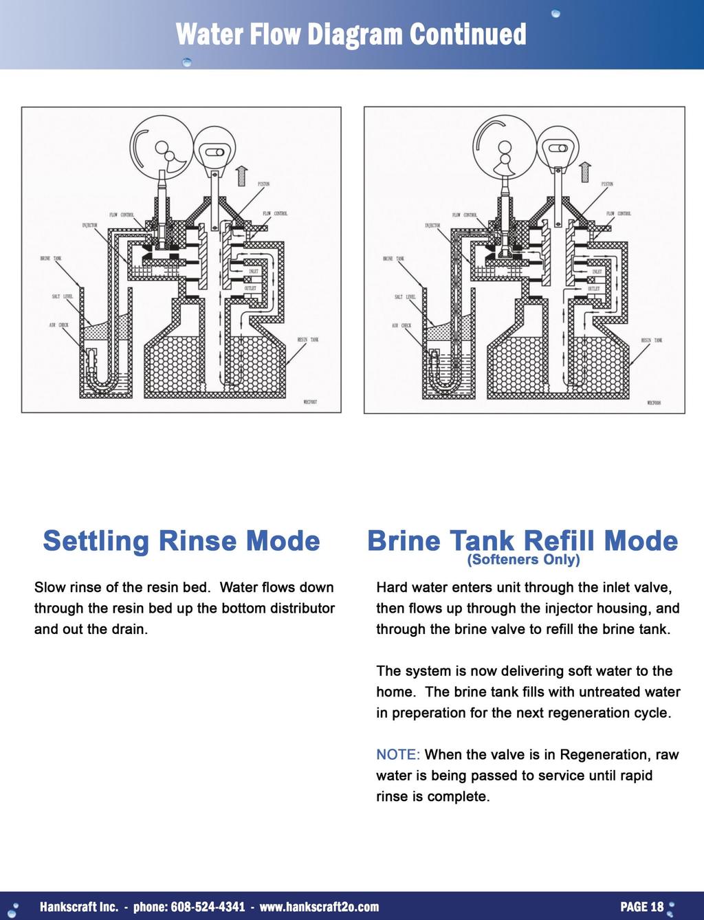
18
19
20 HD-SMM DIGITAL MECHANICAL CONTROL VALVE ASSEMBLY
21 HD-SMM Digital Mechanical Control Valve Assembly Parts List Item No. Description Quantity Item No. Description Quantity 1 Screw 2 14 Back Cover 1 2 Bracket 1 15 Gasket 1 3 Pin 1 16 Brine Cam 1 4 Pinion 1 17 Gasket 1 5 Main Drive Gear & Shaft 1 18 Ball 2 6 Spring 1 19 Spring 2 7 Idler Gear 1 20 Cycle Actuator Arm 1 8 Drive Gear 1 21 Circuit Board Assembly 1 9 Motor Mounting Plate 1 22 Front Cover 1 10 Screw Panel Label 1 11 Motor 1 24 Transformer 1 12 Screw 2 25 Connector Assembly 1 13 Wire Connector 2 26 Strain Relief 1
22 HD-FTC DIGITAL FILTER CONTROL VALVE ASSEMBLY
23 HD-FTC Digital Filter Control Valve Assembly Parts List Item No. Description Quantity Item No. Description Quantity 1 Digital Bracket Frame 1 19 Gear, Passive 1 2 Label, Tested 1 20 Gear, Main Driving 1 3 Seal 2 21 Spring, Button 1 4 Indicator 1 22 Button, White 1 5 Magnet, Meter 1 23 Pin, Motor 1 6 Screws Screws, Front Cover 2 7 PCB, HD 1 25 Gear, Brine Piston 1 8 Cover, Front 1 26 Washer 1 9 Label, Front 1 27 Clip Pad 1 10 Label, Flow 1 28 Cord Clip 1 11 Label, Logo 1 29 Power Cable 1 12 Label, Serial # 1 30 Spring, Main Piston Gear 2 13 Label, Back 1 31 Ball 2 14 Cover, Back 1 32 Gear, Main Piston 1 15 Wire Connectors 2 33 Screw, Main Piston Gear 1 16 Screws, Motor 2 34 Zip Tie 1 17 Motor 1 35 Power Adaptor 1 18 Motor Mount Plate 1
24 HD Valve Body Assembly
25 HD Valve Body Parts List Item No. Description Quantity Item No. Description Quantity 1 Retainer Ring 1 26 Drain Elbow Barb 1 2 Washer 1 27 O-Ring 1 3 Brine Valve Stem 1 28 Bushing 1 4 Spring 1 29 DLFC Button 1 5 Brine Valve Cap 1 30 O-Ring 1 6 O-Ring 2 31 O-Ring 1 7 Brine Valve Spacer 1 32 Adaptor Coupling 2 8 O-Ring 2 33 O-Ring 4 9 Brine Valve Seat 1 34 Yoke 1 10 Air Disperser 1 35 Screw 2 11 O-Ring 1 36 Clip 1 12 O-Ring 2 37 Valve Body 1 13 Softener Injector Body 1 38 Spacer 4 14 Injector Throat 1 39 Seal 5 15 Injector Nozzle 1 40 Piston 1 16 Injector Filter Screen 1 41 Piston Retainer 1 17 O-Ring 1 42 O-Ring Retainer 1 18 Injector Cover 1 43 End Plug 1 19 Screw 2 44 Piston Rod 1 20 Fitting Nut 1 45 Pin 1 21 BLFC Fitting 1 46 Drive Link 1 22 BLFC Button 1 47 End Plug Retainer 1 23 BLFC Button Retainer 1 48 Screw 3 24 O-Ring 1 49 Filter Injector Body 1 25 Retainer Latch 1 50 Screw 2
26 HD - Flow Meter Assembly Item No. Description Quantity 1 Harness Assembly 1 2 Screw 2 3 Flow Straightener 1 4 O-Ring 4 5 Meter Body Assembly 1 6 Clip 2 HD Wiring Diagram


27 Plastic Bypass (yoke required with bypass, available in ¾ & 1 ) Stainless Bypass (available in ¾ & 1 )
28 Bypass and Bypass Mixing Valve FLOW RATE 16 POSITION GPM 8 GPM 4 GPM 2.6 GPM 1.3 GPM.5 GPM 29% 31% 35% 39% 47% 65% 23% 26% 29% 31% 40% 57% 16% 17% 19% 22% 29% 42% 9% 11% 12% 14% 18% 32%
29 Replace Brine Valve, Injectors, and Screen 1. Unplug electrical cord from outlet. 2. Turn off water supply to system. 3. Relieve water pressure in the valve by advancing it to Backwash position momentarily. Return the valve to the In Service position. 4. Disconnect brine tube and drain line connections at the injector body. 5. Remove the two injector body mounting screws. The injector and brine module can now be removed from the control valve. Remove and discard valve body O-Rings. 6. Replace brine valve. a. Pull brine valve from injector body, also remove and discard O-Ring at bottom of brine valve hole. b. Apply silicone lubricant to new O-Ring and reinstall at bottom of brine valve hole. c. Apply silicone lubricant to O-Ring on new valve assembly and press into brine valve hole. The shoulder on bushing should be flush with the injector body. 7. Replace injectors and screen. a. Remove injector cap and screen, discard O-Ring. Unscrew injector nozzle and throat from injector body. b. Screw in new injector throat and nozzle, be sure they are seated tightly. Install a new screen. c. Apply silicone lubricant to new O-Ring and install around oval extension on injector cap. 8. Apply silicone lubricant to three new O-Rings and install over three bosses on injector body. 9. Insert screws with washers through injector cap and injector. Place this assembly through hole in timer housing and into mating holes in the valve body. Tighten screws. 10. Reconnect brine tube and drain line. 11. Return bypass to In Service position. Water pressure automatically builds in the system. Note: Be sure to shut off any bypass line. 12. Check for leaks at all seal areas. Check drain seal with the valve in the Backwash position. 13. Plug electrical cord into outlet. 14. Set time of day. Be sure to return the control valve to the In Service position. 15. Make sure there is enough brine in the brine tank. 16. Rotate program wheel counterclockwise until it stops at regeneration position. 17. Start regeneration cycle manually if water is hard.
30 Replace Timer 1. Unplug electrical cord from outlet. 2. Turn off water supply to system. 3. Relieve water pressure in the system by putting the valve in the Backwash position momentarily. Return the valve to the In Service position. 4. Pull cable out of meter cover. Remove the valve back cover. 5. Remove screw and washer at drive yoke. Remove timer mounting screws. The entire timer assembly now lifts off easily. 6. Put new timer on top of valve. Be sure drive pin on main gear engages slot in drive yoke (rotate control know if necessary). 7. Replace timer mounting screws. Replace screw and washer at drive yoke. 8. Return bypass to normal In Service position. Water pressure automatically builds in the system. Note: Be sure to shut off any bypass line. 9. Plug electrical cord into outlet. 10. Set time of day. Be sure to return the control valve to the In Service position. 11. Replace the control valve back cover. Be sure grommet at cable hole is in place. 12. Make sure there is enough brine in the brine tank. 13. Rotate program wheel counterclockwise until it stops at Regeneration position. 14. Start regeneration cycle manually if water is hard. 15. Plug cable into meter cover. Rotate cable to align drive flat if necessary.
31 Replace Piston Assembly 1. Unplug electrical cord from outlet. 2. Turn off water supply to system. 3. Relieve water pressure in the system by putting the valve in the Backwash position momentarily. Return the valve to the In Service position. 4. Pull cable out of meter cover. Remove the valve back cover. 5. Remove screw and washer at drive yoke. Remove timer mounting screws. The entire timer assembly now lifts off easily. Remove end plug retainer plate. 6. Pull upward on end of piston yoke until assembly is out of valve. 7. Inspect the inside of the valve to make sure that all spacers and seals are in place, and that there is no foreign matter that would interfere with the valve operation. 8. Take new piston assembly as furnished and push piston into valve by means of the end plug. Twist yoke carefully in a clockwise direction to properly align it with drive gear. Replace end plug retainer plate. 9. Place timer on top of valve. Be sure drive pin on main gear engages slot in drive yoke (rotate control knob if necessary). 10. Replace timer mounting screws. Replace screw and washer at drive yoke. 11. Return bypass to normal In Service position. Water pressure automatically builds in the system. Note: Be sure to shut off any bypass line. 12. Plug electrical cord into outlet. 13. Set time of day. Be sure to return the control valve to the In Service position. 14. Replace the control valve back cover. Be sure grommet at cable hole is in place. 15. Make sure there is enough brine in the brine tank. 16. Rotate program wheel counterclockwise until it stops at Regeneration position. 17. Start regeneration cycle manually if water is hard. 18. Plug cable into meter cover. Rotate cable to align drive flat if necessary.
32 Replace Seals and Spacers 1. Unplug electrical cord from outlet. 2. Turn off water supply to system. 3. Relieve water pressure in the system by putting the valve in the Backwash position momentarily. Return the valve to the In Service position. 4. Pull cable out of meter cover. Remove the valve back cover. 5. Remove screw and washer at drive yoke. Remove timer mounting screws. The entire timer assembly now lifts off easily. Remove end plug retainer plate. 6. Pull upward on end of piston rod yoke until assembly is out of valve. Remove and replace seals and spacers with fingers. 7. Place timer on top of valve. Be sure drive pin on main gear engages slot in drive yoke (rotate control knob if necessary). 8. Replace timer mounting screws. Replace screw and washer at drive yoke. 9. Return bypass to normal In Service position. Water pressure automatically builds in the system. Note: Be sure to shut off any bypass line. 10. Plug electrical cord into outlet. 11. Set time of day. Be sure to return the control valve to the In Service position. 12. Replace the control valve back cover. Be sure grommet at cable hole is in place. 13. Make sure there is enough brine in the brine tank. 14. Rotate program wheel counterclockwise until it stops at Regeneration position. 15. Start regeneration cycle manually if water is hard. 16. Plug cable into meter cover. Rotate cable to align drive flat if necessary.
33 Replace Meter 1. Unplug electrical cord from outlet. 2. Turn off water supply to system. 3. Relieve water pressure in the system by putting the valve in the Backwash position momentarily. Return the valve to the In Service position. 4. Pull cable out of meter cover. 5. Remove two screws and clips at bypass valve or yoke. Pull resin tank away from plumbing connections. 6. Remove two screws and clips at control valve. Pull meter module out of control valve. 7. Apply silicone lubricant to four new O-rings and assemble to four ports on new meter module. 8. Assemble meter to control valve. Note: Meter portion of module must be assembled at valve outlet. 9. Attach two clips and screws at control valve. Be sure clip legs are firmly engaged with lugs. 10. Push resin tank back to the plumbing connections and engage meter ports with bypass valve or yoke. 11. Attach two clips and screws at bypass valve or yoke. Be sure clip legs are firmly engaged with lugs. 12. Return bypass to normal In Service position. Water pressure automatically builds in the system. Note: Be sure to shut off any bypass line. 13. Check for leaks at all seal areas. 14. Plug electrical cord into outlet. 15. Set time of day. Be sure to return the control valve to the In Service position. 16. Replace the control valve back cover. Be sure grommet at cable hole is in place. 17. Make sure there is enough brine in the brine tank. 18. Rotate program wheel counterclockwise until it stops at Regeneration position. 19. Start regeneration cycle manually if water is hard. 20. Plug cable into meter cover. Rotate cable to align drive flat if necessary.
34 Replace Meter Cover and/or Impeller 1. Unplug electrical cord from outlet. 2. Turn off water supply to system. 3. Relieve water pressure in the system by putting the valve in the Backwash position momentarily. Return the valve to the In Service position. 4. Pull cable out of meter cover. 5. Remove four screws on cover. Lift cover off of meter module, discard O-ring. 6. Remove and inspect impeller for gear or spindle damage, replace if necessary. 7. Apply silicone lubricant to new O-ring and assemble to the smallest diameter on meter cover. 8. Assemble cover to meter module. Be sure impeller spindle enters freely into cover. Press firmly on cover and rotate if necessary to assist in assembly. Replace four screws and tighten. 9. Return bypass to normal In Service position. Water pressure automatically builds in the system. Note: Be sure to shut off any bypass line. 10. Check for leaks at all seal areas. 11. Plug electrical cord into outlet. 12. Set time of day. Be sure to return the control valve to the In Service position. 13. Rotate program wheel counterclockwise until it stops at Regeneration position. 14. Start regeneration cycle manually if water is hard. 15. Plug cable into meter cover. Rotate cable to align drive flat if necessary.
35 Problem Cause Correction 1. Softener Fails to Regenerate 2. Softener Delivers Hard Water 3. Unit uses too much salt. 4. Loss of water pressure. A. Electrical service to unit has been interrupted. B. Timer is not operating properly. C. Defective valve drive motor. D. Timer programmed incorrectly. A. Bypass valve is open. B. No salt in brine tank. C. Injectors or screen plugged. D. Insufficient water flowing into brine tank. E. Hot water tank hardness. F. Leak at distributor tube. G. Internal valve leak. H. Flow meter jammed. I. Flow meter cable disconnected or not plugged into meter. J. Programmed incorrectly. A. Improper salt setting. B. Excessive water in brine tank. C. Programmed incorrectly. A. Iron buildup in line to water conditioner. B. Iron buildup in water conditioner. C. Inlet of control plugged due to foreign material broken loose from pipes by recent work done on plumbing system. A. Assure permanent electrical service, check fuse, plug, switch, etc. B. Replace timer. C. Replace drive motor. D. Check programming and reset as needed. A. Close bypass valve. B. Add salt to brine tank and maintain salt level above water level. C. Replace injectors and screens. D. Check brine tank fill time and clean brine line flow control if plugged. E. Drain the hot water tank. F. Make sure distributor tube is not cracked. Check O-ring and tube pilot. G. Replace Seals and spacers and/or piston. H. Remove obstruction from flow meter. I. Check meter cable connection to timer and meter. J. Reprogram the control to the proper regeneration type, inlet water hardness, capacity of flow meter size. A. Check salt usage and salt setting. B. See problem 7. C. Check programming and reset as needed. A. Clean line to water conditioner. B. Clean control and add resin cleaner to resin bed. Increase frequency of regeneration. C. Remove piston and clean control.
36 Problem Cause Correction 5. Softener Fails to Regenerate 6. Softener Delivers Hard Water 7. Unit uses too much salt. 8. Loss of water pressure. E. Electrical service to unit has been interrupted. F. Timer is not operating properly. G. Defective valve drive motor. H. Timer programmed incorrectly. K. Bypass valve is open. L. No salt in brine tank. M. Injectors or screen plugged. N. Insufficient water flowing into brine tank. O. Hot water tank hardness. P. Leak at distributor tube. Q. Internal valve leak. R. Flow meter jammed. S. Flow meter cable disconnected or not plugged into meter. T. Programmed incorrectly. D. Improper salt setting. E. Excessive water in brine tank. F. Programmed incorrectly. D. Iron buildup in line to water conditioner. E. Iron buildup in water conditioner. F. Inlet of control plugged due to foreign material broken loose from pipes by recent work done on plumbing system. E. Assure permanent electrical service, check fuse, plug, switch, etc. F. Replace timer. G. Replace drive motor. H. Check programming and reset as needed. K. Close bypass valve. L. Add salt to brine tank and maintain salt level above water level. M. Replace injectors and screens. N. Check brine tank fill time and clean brine line flow control if plugged. O. Drain the hot water tank. P. Make sure distributor tube is not cracked. Check O-ring and tube pilot. Q. Replace Seals and spacers and/or piston. R. Remove obstruction from flow meter. S. Check meter cable connection to timer and meter. T. Reprogram the control to the proper regeneration type, inlet water hardness, capacity of flow meter size. D. Check salt usage and salt setting. E. See problem 7. F. Check programming and reset as needed. D. Clean line to water conditioner. E. Clean control and add resin cleaner to resin bed. Increase frequency of regeneration. F. Remove piston and clean control.
37 9. Loss of resin through drain line. 10. Iron in conditioned water. 11. Excessive water in brine tank. 12. Salt water in service line. 13. Softener fails to draw brine. 14. Control cycles continuously. 15. Drain flows continuously. A. Air in water system. B. Drain line flow control is too large. A. Fouled resin bed. B. Iron content exceeds recommended parameters. A. Plugged drain line flow control. B. Brine valve failure. C. Improper programming. A. Plugged injector system. B. Timer not operating properly. C. Foreign material in brine valve. D. Foreign material in brine line flow control. E. Low water pressure. F. Improper programming. A. Drain line flow control is plugged. B. Injector is plugged. C. Injector screen plugged. D. Line pressure is too low. E. Internal control leak. F. Improper programming. G. Timer not operating properly. A. Time not operating properly. B. Faulty micro switches and or harness. C. Faulty cycle cam operation. A. Foreign material in control. B. Internal control leak. C. Control valve jammed in brine or backwash position. D. Timer motor stopped or jammed. E. Timer not operating properly. A. Assure that well system has proper air eliminator control check for dry well condition. B. Ensure drain line flow control is sized correctly. A. Check backwash, brine draw and brine tank fill. Increase frequency of regeneration. Increase backwash time. B. Add iron removal filter or system. A. Clean flow control. B. Replace brine valve. C. Check programming and reset as needed. A. Clean injector and replace screen. B. Replace timer. C. Clean or replace brine valve. D. Clean brine line flow control. E. Raise water pressure. F. Check programming and reset as needed. A. Clean drain line flow control. B. Clean or replace injectors. C. Replace screen. D. Increase line pressure (line pressure must be at least 25 psi at all times.) E. Change seals and spacers and/or piston assembly. F. Check programming and reset as needed. G. Replace timer. A. Replace timer. B. Replace faulty micro switch or harness. C. Replace cycle cam or reinstall. A. Remove piston assembly, inspect and remove foreign material. B. Replace seals and/or piston assembly. C. Replace piston and seals and spacers. D. Replace timer motor, check for missing teeth on gears. E. Replace timer.
38 Problem Cause Correction 1. Filter fails to backwash 2. Filter bleeds iron 3. Loss of water pressure 4. Loss of filter media through drain line 5. Drain flows continuously A. Electrical service to unit has been interrupted. B. Timer is defective. C. Power failure. A. Bypass valve is open. B. Excessive water usage. C. Hot water tank rusty. D. Leak at distributor tube. E. Fouled filter media bed. F. Inadequate backwash flow rate. A. Iron or turbidity build-up in water filter. B. Inlet plugged due to foreign material broken loose from pipes. A. Broken or missing upper or lower basket. A. Foreign material in control. B. Internal control leak. C. Control valve jammed in rinse or backwash. A. Assure permanent electrical service (check fuse, plug, pull chain or switch). B. Replace timer. C. Reset time of day. A. Close bypass valve. B. Increase days between regenerations (see timer instructions), make sure that there is not a leaking valve in the toilet or sinks. C. Flush out the hot water tank. D. Verify distributor tube is not cracked, check O-rings and tube pilot. E. Replace bed. F. Make sure filter has correct DLFC. Be sure flow control is not clogged or drain line restricted. Be sure water pressure has not dropped. A. Reduce days between backwashing so filter backwashes more often, make sure filter is sized large enough to handle water usage. B. Remove piston and clean control. A. Replace install or replace basket. A. Remove piston assembly and inspect bore, remove foreign material and check control in various cycle positions. B. Replace seals and/or piston assembly. C. Replace piston, seals and spacers (and drive motor if necessary).
, warrants its products are free from defects in material and workmanship only, when properly installed, operated, and maintained.")

39 As described herein, Hankscraft Inc., d/b/a H20 Products ( Hankscraft ), warrants its products are free from defects in material and workmanship only, when properly installed, operated, and maintained. This warranty is subject to the exceptions herein. Hankscraft warrants to the original owner that the items listed below, excluding but not limited to wear parts like O-rings, gaskets and seals, will be free from defects in materials and workmanship for the period of time specified below from the original purchase date. Control valves and all internal valve parts and the salt storage tank FIVE YEARS Mineral tank TEN YEARS Any other component ONE YEAR Ceramic disc for rotary valve (applicable to RevV series valves only) LIFETIME RO and UF Filter Systems- ONE YEAR Media/resin is not warrantied due to water supply quality differences Any parts used for replacement are warrantied for the remainder of the original warranty period applicable to the part from the date of manufacture so long as the parts are installed by a Hankscraft factory trained and authorized installer. Hankscraft s obligation by this Limited Warranty, at is option, is to repair or replace any warrantied product only. Labor for repair or replacement is not included as part of this warranty. Prior to returning the product to Hankscraft, a valid return materials authorization number must be obtained from Hankscraft. Any product returned to Hankscraft without a valid return authorization number will be rejected. Any product found to be defective will, at the sole discretion of Hankscraft, be repaired or replaced. Hankscraft is not responsible for shipping cost to the repair facility. This section lists the sole remedies for any valid warranty claim. This warranty does not apply to defects reported to Hankscraft outside of the warranty period. This warranty does not apply to defects caused by installing, operating, servicing, modifying, repairing or maintaining (or lack of maintaining) the product outside of Hankscraft s recommendations. Filters, membrane elements and flow restrictors that become fouled or plugged due to excessive turbidity, dissolved solids, or microorganisms are not covered by this warranty. This warranty does not apply to defects caused by damage during shipment, neglect, misuse, modification, accident, noncompliance with local codes and ordinances, hot water, frozen water, sediment, corrosive liquids, gases, chemicals, bacteria, animals, sand, salt, flood, wind, fire, outdoor installations where the product is not reasonably covered, pneumatic use, natural disasters, war, terrorism or acts of God. No other person is authorized to make any other warranty on behalf of Hankscraft either during or after the applicable warranty period. Hankscraft assumes no liability for determining the proper products and equipment or installation necessary to meet the requirements of the user of the product, and Hankscraft does not authorize others to assume such liability on its behalf. THE WARRANTIES AND REMEDIES HEREIN ARE EXCLUSIVE AND IN LIEU OF ANY AND ALL OTHER WARRANTIES OR REMEDIES EITHER EXPRESSED OR IMPLIED, HEREIN OR ELSEWHERE, INCLUDING WITHOUT LIMITATION WARRANTIES OF MERCHANTABILITY, FITNESS FOR ANY PARTICULAR PURPOSE, NON-INFRINGEMENT OR WARRANTIES RESULTING FROM COURSE OF PERFORMANCE, COURSE OF DEALING OR FROM USAGE OF TRADE. HANKSCRAFT HEREBY DISCLAIMS ALL OTHER WARRANTIES. HANKSCRAFT S LIABILITY SHALL NOT EXCEED THE COST OF THE PRODUCT. HANKSCRAFT IS NOT RESPONSIBLE FOR INCIDENTAL OR CONSEQUENTIAL DAMAGES OR EXPENSES OF ANY KIND WHATSOEVER, INCLUDING LOSS OF PROFITS, UNDER ANY CIRCUMSTANCES AND REGARDLESS OF WHETHER HANKSCRAFT WAS AWARE OF THE POSSIBILITY OF ANY SUCH LOSS.
40 Thank you for choosing this Hankscraft H20 PRODUCTS water treatment system. Please contact us with questions. Hankscraft H2O Products 300 Wengel Drive Reedsburg, WI (608) Updated May 2015
HD / HDL Valves & Systems Service Manual
 Innovative Solutions for Your Water HD / HDL Valves & Systems Service Manual Hankscraft Runxin, LLC 300 Wengel Drive Reedsburg, WI 53959 608.524.9465 sales@hrh2o.com hrh2o.com 2 Table of Contents 1. Introduction...
This unit is superb for commercial applications where soft water is required 100% of the time.
 Model 9000 water softener Rayne Infinity Water Softener This image portrays the locations the 9000 water softner unit is best suited; a car wash; laundry; motel and restaurants. This model 9000 water softener
Owner's Manual. WS Series. Water Softener
 Owner's Manual WS-165-150 Series Water Softener Table of Contents WHAT'S INCLUDED 3 OPERATING CONDITIONS 4 ASSEMBLY INSTRUCTIONS 6 FLUSHING THE WATER LINES 13 MASTERPROGRAMMING 14 PROGRAMMING KEYAND GENERAL
1850 Series TRIPLE TREAT Operation Manual
 1850 Series TRIPLE TREAT Operation Manual BRINE TANK RESIN TANK CARBON TANK System shown with optional tank jackets. Note: 1. Read all instructions carefully before operation. 2. Avoid pinched o-rings
RevV4 Valves & Systems Service Manual. Innovative Solutions for Your Water
 Innovative Solutions for Your Water RevV4 Valves & Systems Service Manual Hankscraft Runxin, LLC 300 Wengel Drive Reedsburg, WI 53959 608.524.9465 sales@hrh2o.com hrh2o.com 2 Table of Contents 1. Introduction...
6700 Valve Downflow. Automatic Water Softeners Operation Manual. Read all instructions carefully before operation. #51431 Rev.
 6700 Valve Downflow Automatic Water Softeners Operation Manual Read all instructions carefully before operation. #51431 Rev. 11/08 US Performance and Specifications Downflow Capacity at Various Salt Dosages
NovoSoft 465 Series SIM Water Softener Operation Manual
 NovoSoft 465 Series SIM Water Softener Operation Manual Note: 1. Read all instructions carefully before operation. 2. Avoid pinched o-rings during installation by applying (provided with install kit) NSF
541D19 SERIES. Technical Manual. A Division of Aquion Partners L.P.
 541D19 SERIES Technical Manual A Division of Aquion Partners L.P. Table of Contents Introduction... Page 1 Technical Specifications... Page 2 Flow Diagrams... Page 3 Injector & Flow Control Selection Injector...
6700 Valve Upflow. Automatic Water Softeners Operation Manual. Read all instructions carefully before operation. #57341 Rev.
 6700 Valve Upflow Automatic Water Softeners Operation Manual Read all instructions carefully before operation. #57341 Rev. 11/08 US Performance and Specifications Upflow Capacity at Various Salt Dosages
Installation & Service Manual
 Installation & Service Manual Table of Contents Unpacking & Inspection... 2 Basic Guidelines... 2 Specifications... 3 Before Starting Installation Where to install the filter... 4 Tools, pipe, fittings
6700XTR Valve Downflow
 6700XTR Valve Downflow Automatic Water Softeners Operation Manual Read all instructions carefully before operation. #51545 Rev. 11/08 US Performance and Specifications Downflow Capacity at Various Salt
Model NFF Iron, Manganese, Hydrogen Sulfide Reduction
 Super Filter Model NFF Iron, Manganese, Hydrogen Sulfide Reduction Operating and Maintenance Manual Page 1 of this manual contains operating conditions. 57055 9/07 Enjoy clean, stain-free laundry and dishes...
Metermatic Water Softener. Operation Manual
 Metermatic Water Softener Operation Manual Page 5 of this manual contains important maintenance procedures for the continued proper operation of your unit. These MUST be performed regularly for your guarantee
MP-MBA-45T-1/60T-1 / 75T-1
 MASTER Water Conditioning Corp. www.masterwater.com Installation and Operation Manual MP-MBA-45T-1/60T-1 / 75T-1 with the 268/762 Logix Control Valve July 2006 Table of Contents Page No. Topic Description
Water Softener Installation / Operation Manual
 Water Softener Installation / Operation Manual BrassMaster and BrassMaster Plus Technical Video Library: http://watercontrolinc.com/residential-technical-support/residential-technical-videos BrassMaster
TITAN VI High Efficiency Water Conditioner Installation and Operation Manual
 TITAN VI High Efficiency Water Conditioner Installation and Operation Manual Manufacturer s Warranty Holts Water Conditioning 369 South Mountainway Drive Orem, UT 84058 801-426-9243 To the original purchaser,
Plumbline 2000 Series Metered Softeners Owners Manual Water Softener Models
 Plumbline 2000 Series Metered Softeners Owners Manual Water Softener Models PS2000M PS2500M PS2700M PS2900M Table of Contents How to Use Soft Water 3 Product Line Overview 5 System Operation 6 System Maintenance
Econoflo SXT Automatic Meter Initiated Water Softener
 Econoflo SXT Automatic Meter Initiated Water Softener Operating and Maintenance Manual Page 5 of this manual contains important maintenance procedures for the continued proper operation of your unit. These
6700XTR Upflow Valve. Water Softener Operation Manual. Read all instructions carefully before operation. #51548 Rev. 2/09
 6700XTR Upflow Valve Water Softener Operation Manual Read all instructions carefully before operation. #51548 Rev. 2/09 Performance and Specifications Item Model Capacity at regeneration salt levels Service
MASTER. Water Conditioning Corp. MP-TS-10T/20T with the 255/762 Logix Control Valve With Vortech. Installation and Operation Manual
 MASTER Water Conditioning Corp. www.masterwater.com Installation and Operation Manual MP-TS-10T/20T with the 255/762 Logix Control Valve With Vortech February 2010 Table of Contents Page No. Topic Description
Plumbline 1000 Series Timered Softeners Owners Manual Water Softener Models
 Plumbline 1000 Series Timered Softeners Owners Manual Water Softener Models PS1000T PS1500T Table of Contents How to Use Soft Water 3 Product Line Overview 5 System Operation 6 System Maintenance and Install
TITAN Pro-Max High Efficiency Upflow Water Conditioner Installation and Operation Manual
 TITAN Pro-Max High Efficiency Upflow Water Conditioner Installation and Operation Manual TITAN VI Pro-Max Manufacturer s Warranty Holts Water Conditioning 369 South Mountainway Drive Orem, UT 84058 801-426-9243
Installation and Operation Manual
 Installation and Operation Manual NOTE: RISER / DISTRIBUTOR PIPE SHOULD BE CUT 1/2 BELOW THE TOP SURFACE OF THE TANK INSERT. MTS 95 System REVISION # 3 REVISION DATE SEPTEMBER 12, 2013 2 Table of Contents
7000 Meter Initiated Valve
 7000 Meter Initiated Valve Water Softener Operation Manual Read all instructions carefully before operation. #51400 Rev. 2/09 Performance and Specifications Item Model Capacity at regeneration salt levels
High Flow 7000 SXT Water Softener
 High Flow 7000 SXT Water Softener Operating and Maintenance Manual WQA Tested and Certified against CSA B483.1 Read all instructions carefully before operation. #54736WQA 3/11 ii Performance Data Sheet
Water Softener Installation Guide Effective for all Softeners from our Range
 Water Softener Installation Guide Effective for all Softeners from our Range Planning Your Installation Always observe the water byelaws. Ensure there is only one rising main, that you have allowed space
Sanitizer Series. Water Conditioners
 Sanitizer Series Water Conditioners TABLE OF CONTENTS Installation Instructions..........................................3-4 Start-up Procedures.............................................5-6 Programming
High Flow 7000 SXT Series Water Softeners
 High Flow 7000 SXT Series Water Softeners Operating and Maintenance Manual Read all instructions carefully before operation. #54736 12/08 Performance and Specifications Model Capacity - Grains Flow Rates
Green Water Systems OWNERS MANUAL. Includes: Installation Procedures, Warranties, Service & Operation Guidelines.
 Green Water Systems OWNERS MANUAL Includes: Installation Procedures, Warranties, Service & Operation Guidelines. GS Elite GS PRO GS1 1 Cu. Ft. S. C. S. GS1.5 1 Cu. Ft. S. C. S. GS2 2 Cu. Ft. S. C. S. 7000
The Inlet and Outlet should be as per below illustration. This will ensure that water will flow through the filter in an upflow configuration
 Owners Manual The Inlet and Outlet should be as per below illustration. This will ensure that water will flow through the filter in an upflow configuration INLET OUTLET NRV Filter FOLLOWTHE INSTALLATION
Owner's Manual. Whole House Water Softener with Triton Electronic Control Valve. or call
 Owner's Manual SoftMAX Whole House Water Softener with Triton Electronic Control Valve ACTIVATE YOUR WARRANTY BY REGISITERING YOUR PRODUCT AT WWW.WATERTECH.COM or call 888-254-8412 Dealer Contact and Product
Fully Automatic Water Softeners
 OWNERS GUIDE TO INSTALLATION AND OPERATION Fully Automatic Water Softeners SINGLE TANK CABINET MODELS TWO TANK MODELS Read the instructions carefully and learn the specific details regarding installation
Installation, Operation and Maintenance Manual. Infusion Residential Water Softener 169-ISF-1C 169-ISF-2C 169-ISF-3C 169-ISF-4C
 Installation, Operation and Maintenance Manual Infusion Residential Water Softener Calcium, magnesium removal system 169-ISF-1C 169-ISF-2C 169-ISF-3C 169-ISF-4C US Water Systems, Inc. 1209 Country Club
Water Softener & Single Tank Triple Treat System Installation Overview. Using 1850 Metered Valves
 Water Softener & Single Tank Triple Treat System Installation Overview Using 1850 Metered Valves System Installation CAUTION: Do not use systems on untreated well water that is microbiologically unsafe.
GRANT-DILLING-HARRIS INC. WATER SOFTENER THEORY OF OPERATION
 GRANT-DILLING-HARRIS INC. WATER SOFTENER THEORY OF OPERATION WATER SOFTENER: The Water Softener requires a 120VAC 2 AMP electrical service and the Water lines in and out need to be sized to the Softener.
Fleck 2510 Softener Installation & Start Up Guide
 Clean Water Made Easy www.cleanwaterstore.com Fleck 2510 Softener Installation & Start Up Guide Thank you for purchasing a Clean Water System! With proper installation and a little routine maintenance
FLECK 5600 WATER SOFTENER INSTALLATION
 FLECK 5600 WATER SOFTENER INSTALLATION Discount Water Softeners recommends using a licensed plumber to install your water softener. The following installation instructions are for use with the water softener
MKTF CRO-Series 5-Stage Reverse Osmosis System Installation and Maintenance Manual
 MKTF - 215 CRO-Series 5-Stage Reverse Osmosis System Installation and Maintenance Manual Please fill out the following information at the time of installation. Save for future reference. Model: Date Code:
Clean Water Made Easy
 Clean Water Made Easy http://www.cleanwaterstore.com Pro-OX 1650 Iron Filter Installation & Start-Up Guide Thank you for purchasing a Clean Water System! With proper installation and a little routine maintenance
FULLY AUTOMATIC WATER SOFTENER
 OWNERS GUIDE TO INSTALLATION AND OPERATION Section: 6.10.130 FM2035 0302 Supersedes 0102 FULLY AUTOMATIC WATER SOFTENER MODEL 340 SAFETY INFORMATION Read the instructions carefully and learn the specific
Fully Automatic Water Softeners
 OWNERS GUIDE TO INSTALLATION AND OPERATION Fully Automatic Water Softeners FW0782 0211 Supersedes 0410 Models S15DC29DR and S15DC39DR SAFETY INFORMATION Read the instructions carefully and learn the specific
Clean Water Made Easy. Fleck 7000 Tannin Filter Installation & Startup Guide. Questions?
 Clean Water Made Easy www.cleanwaterstore.com Fleck 7000 Tannin Filter Installation & Startup Guide For Tannin Filters with Vortech Distributor Screen Thank you for purchasing a Clean Water System! With
Installation Instructions and Owner s Manual. CITY Series Water Softening and Filter System
 Installation Instructions and Owner s Manual CITY Series Water Softening and Filter System First Sales, LLC 12630 US Highway 33 N Churubusco, IN 46723 Phone (260) 693-1972 Fax (260) 693-0602 CITY Series
FUSION PROFESSIONAL-GRADE METERED NITRATE REMOVAL SYSTEM
 Visit us online at www.uswatersystems.com FUSION PROFESSIONAL-GRADE METERED NITRATE REMOVAL SYSTEM Owners Manual Models: 086-FNLT-XXX-NT REVISION # 1.0 REVISION DATE : September 18, 2018 US Water Systems
Installation & Service Guide
 Reverse Osmosis Ontario Soft Water.ca Kitchener, Canada 519-579-0500 Installation & Service Guide Pentair 75 gpd Encapsulated Membrane System Standard System 75gpd Membrane Your New Reverse Osmosis System
ProFlo SXT Valve Downflow / Upflow
 ProFlo SXT Valve Downflow / Upflow Automatic Water Softeners Operation Manual Read all instructions carefully before operation. #54719 Rev. 1/09 US Performance and Specifications Downflow Upflow Capacity
89 BIF/BAF USER MANUAL
 89 BIF/BAF USER MANUAL Owners Manual 1. Read all instructions carefully before operation. 2. Avoid pinched o-rings during installation by applying (provided with install kit) NSF certified lubricant to
Installation Instructions PP-AS20 Anti-Scale System
 Installation Instructions PP-AS20 Anti-Scale System THIS UNIT MUST BE INSTALLED BY A LICENSED PLUMBER TO VALIDATE THE WARRANTY. COMPONENTS PP-AS20 Filter Housing PP-AS20R Filter Cartridge Installation
Clean Water Made Easy. CWS Time Clock Softener Installation & Start Up Guide. Questions?
 Clean Water Made Easy www.cleanwaterstore.com CWS Time Clock Softener Installation & Start Up Guide Thank you for purchasing a Clean Water System! With proper installation and a little routine maintenance
Kinetico 2060f OD Sulfur Guard Installation Instructions
 SAFETY GUIDELINES Read all steps, guides, and rules carefully before installing and using the Kinetico 2060f OD Sulfur Guard. Check your local building and sanitation codes for installation compliance.
Autotrol Performa FA Valve
 Autotrol Performa FA Valve With 400 Series Control Water Conditioning Control System Dealer Installation, Operation, and Maintenance Manual Table of Contents Installation................................
Tier1 Water Home Filtration System
 Tier1 Water Home Filtration System Carbon+KDF Series OWNERS MANUAL BEFORE YOU BEGIN INSTALLATION, READ THIS ENTIRE MANUAL. FOLLOW THE INSTALLATION INSTRUCTIONS CAREFULLY. 1. Avoid pinched o-rings during
GROWMAX WATER Perfect Water for Plants and Gardens
 GROWMAX WATER Perfect Water for Plants and Gardens WATER SYSTEMS FOR HYDROPONICS AND GARDENING GROWMAX 3000 Ultra-Pure Reverse Osmosis Water System Up to 3000 L/D of Pure Water Don't forget to register
Fully Automatic Water Filters
 INSTALLATION INSTRUCTIONS Fully Automatic Water Filters INSTALLATION INFORMATION Model No. Unit Date Code Date Installed WATER ANALYSIS RECORD Hardness GPG Sulfur PPM Iron PPM ph Manganese PPM Tannins
OWNER S MANUAL. Premium Series Two Tank 1-PLUS-1 Water Conditioner & Whole House Filters
 OWNER S MANUAL Premium Series Two Tank 1-PLUS-1 Water Conditioner & Whole House Filters Congratulations! You ve selected our Premium Series Two Tank 1-PLUS-1 water conditioner and whole house filter for
765 Valve Filters (Taste & Odor, Nextsand, Multimedia, Neutralizer)
") 765 Valve Filters (Taste & Odor, Nextsand, Multimedia, Neutralizer) Owners Manual FOLLOWTHE INSTALLATION INSTRUCTIONS CAREFULLY. FAILURE TO INSTALL THE UNIT PROPERLY VOIDS THE WARRANTY. BEFORE YOU BEGIN
765 Valve Filters (Taste & Odor, Nextsand, Multimedia, Neutralizer) Owners Manual FOLLOWTHE INSTALLATION INSTRUCTIONS CAREFULLY. FAILURE TO INSTALL THE UNIT PROPERLY VOIDS THE WARRANTY. BEFORE YOU BEGIN
565 TLC Softener & Tannins Reduction System
 565 TLC Softener & Tannins Reduction System Owners Manual 1. Read all instructions carefully before operation. 2. Avoid pinched o-rings during installation by applying (provided with install kit) NSF certified
Spectrum TM. Installation, Service & Operation Manual O FLO. SoftH 2. Water Softener. Table of Contents
 Installation, Service & Operation Manual SoftH 2 O FLO Water Softener Table of Contents 1. Description & Equipment Adjustments p.2 2. Components, Features & Functions p.3 3. Valve User Interface p.4 4.
The WateRx Plant. Features/Benefits. Applications (for municipal water usage) Great water throughout the home or office. Automatic weekly backwash
 Great water throughout the home or office. Automatic weekly backwash") The WateRx Plant Features/Benefits Great water throughout the home or office Automatic weekly backwash Simple media recharge each year Direct drop ship to customer via UPS Easily tailored to meet specific
The WateRx Plant Features/Benefits Great water throughout the home or office Automatic weekly backwash Simple media recharge each year Direct drop ship to customer via UPS Easily tailored to meet specific
Installation and Operation Manual
 Installation and Operation Manual 95 BIF / BAF Filter Manual NOTE: 1.5 RISER / DISTRIBUTOR PIPE SHOULD BE CUT 1/2 BELOW THE TOP SURFACE OF THE TANK INSERT. 1. Read all instructions carefully before operation.
Clean Water Made Easy
 Clean Water Made Easy http://www.cleanwaterstore.com Pro-OX 5700-E Iron Filter Installation & Start-Up Guide Thank you for purchasing a Clean Water System! With proper installation and a little routine
Installation Instructions and Owner s Manual. FSN Series. Nitrate Removal Water Softening System
 Installation Instructions and Owner s Manual FSN Series Nitrate Removal Water Softening System First Sales, LLC 12630 US Highway 33 N Churubusco, IN 46723 Phone (260) 693-1972 Fax (260) 693-0602 FSN Series
Commercial Water Softener
 Commercial Water Softener Owners Manual 1. Read all instructions carefully before operation. 2. Avoid pinched o-rings during installation by applying (provided with install kit) NSF certified lubricant
Installation Instructions and Owner s Manual. FS, FSM, & FES Series. Water Softening System
 Installation Instructions and Owner s Manual FS, FSM, & FES Series Water Softening System MODEL NUMBERS: Time Clock Mechanical Metered FSL Series FSLM Series FS Series FSM Series High Efficiency High Efficiency
Installation Manual & Owner s Guide
 Installation Manual & Owner s Guide Table of Contents Benefits of Iron Shield +... 1 How Iron Shield + Works... 2 Unpacking & Inspection... 3 Basic Guidelines... 3 Specifications... 4 Regeneration Schedules...
Installation Instructions and Owner s Manual. N, NMS, NES, & INT2 Series. Water Softening Systems
 Installation Instructions and Owner s Manual N, NMS, NES, & INT2 Series Water Softening Systems MODEL NUMBERS: Time Clock Mechanical Metered NC Series NMCS Series N Series NMS Series High Efficiency High
Owner s Manual / 5600 Econominder
 5600 / 5600 Econominder Owner s Manual For questions or in case of emergency, please call your local service technician (preferably the one who installed the system). Product Features, Benefits, & Job
765 IS Greensand Filter. Proud member of Canadian Institute of Plumbing & Heating. Proud member of Canadian Water Quality Association.
 765 IS Greensand Filter Proud member of Canadian Institute of Plumbing & Heating. Owners Manual Proud member of Canadian Water Quality Association. 1. Read all instructions carefully before operation.
ispring Whole House Water Filter Systems USER S MANUAL
 ispring Whole House Water Filter Systems USER S MANUAL Version 2014-5 Introduction Congratulations on your purchase of the ispring Whole House Water Filter system. Featuring a three-stage filtration process,
AUTOTROL 363TC AUTOMATIC FILTER VALVE SERVICE MANUAL
 AUTOTROL 363TC AUTOMATIC FILTER VALVE SERVICE MANUAL 2013 Pentair Residential Filtration, LLC www.pentairaqua.com/pro TABLE OF CONTENTS MANUAL OVERVIEW... 2 SAFETY INFORMATION... 2 TYPICAL TOOLS AND FITTINGS
5700-E Sediment Filter Installation & Start-Up Guide
 Clean Water Made Easy www.cleanwaterstore.com 5700-E Sediment Filter Installation & Start-Up Guide Thank you for purchasing a Clean Water System! With proper installation and a little routine maintenance
Fleck 7000 Sediment Filter Installation & Start-Up Guide
 Clean Water Made Easy www.cleanwaterstore.com Fleck 7000 Sediment Filter Installation & Start-Up Guide Thank you for purchasing a Clean Water System! With proper installation and a little routine maintenance
7800 Neutralizer Installation & Start-Up Guide
 Clean Water Made Easy www.cleanwaterstore.com 7800 Neutralizer Installation & Start-Up Guide Thank you for purchasing a Clean Water System! With proper installation and a little routine maintenance your
IMPORTANT! ank You! Model: Twist-In 100 GPD, 3-Stage RO Unit. Installation, Operation & Maintenance Guide
 Twist-In 00 GPD, 3-Stage RO Unit WARNING: Please read carefully before proceeding with installation. Your failure to follow any attached instructions and operating parameters may lead to the product s
PRF-RO Pentair Reverse Osmosis System Installation and Maintenance Manual SAFETY GUIDES THE BASIC REVERSE OSMOSIS SYSTEM. Tools and Materials Required
 PRF-RO Pentair Reverse Osmosis System Installation and Maintenance Manual SAFETY GUIDES Read and follow all steps and guides carefully before installing and using your reverse osmosis system. Do not use
Tier1 Water Home Filtration System
 Tier1 Water Home Filtration System Salt-Free Softener OWNERS MANUAL BEFORE YOU BEGIN INSTALLATION, READ THIS ENTIRE MANUAL. FOLLOW THE INSTALLATION INSTRUCTIONS CAREFULLY. 1. Avoid pinched o-rings during
Fleck 5600 SXT. Installation Guide. Make a list of all of the plumbing fittings needed to install; a typical list looks like this:
 Installation Guide Before you assemble your new system, be sure that the following conditions have been met for placement of your softener: Getting Started Level, firm surface, such as concrete, on which
475 PRO SERIES Reverse Osmosis System Installation & Operation Manual
 PLEASE READ ALL INSTRUCTIONS BEFORE INSTALLING AND USING THIS SYSTEM 475 PRO SERIES Reverse Osmosis System Installation & Operation Manual Model STAGE 1 STAGE 2 STAGE 3 STAGE 4 OUTPUT 475 SEDIMENT CARBON
5900S Softener Installation & Start-Up Guide
 Clean Water Made Easy www.cleanwaterstore.com 5900S Softener Installation & Start-Up Guide Thank you for purchasing a Clean Water System! With proper installation and a little routine maintenance your
565IS Greensand Filter. Proud member of Canadian Institute of Plumbing & Heating. Proud member of Canadian Water Quality Association.
 565IS Greensand Filter Proud member of Canadian Institute of Plumbing & Heating. Owners Manual Proud member of Canadian Water Quality Association. 1. Read all instructions carefully before operation. 2.
Installation, Operation, and Maintenance Manual. Waterlogix Metered Residential Water Softener
 Installation, Operation, and Maintenance Manual Waterlogix Metered Residential Water Softener Waterlogix WLS-075 Waterlogix WLS-075C Waterlogix WLS-100 Waterlogix WLS-100C Waterlogix WLS-150 Waterlogix
INSTALLATION & SERVICE MANUAL
 INSTALLATION & SERVICE MANUAL Countertop Reverse Osmosis Systems Series CT System Tested and Certified by WQA against NSF/ANSI Standard 58 for the reduction of Arsenic, Barium, Cadmium, Copper, Cyst, Hexavalent
Installation, Operation, and Maintenance Manual
 Installation, Operation, and Maintenance Manual Product Preservers Anti-Scale System Chemical-Free, Salt-Free Scale Prevention Introduction The Product Preservers Anti-Scale System will condition the tap
785 Upflow Water Softener
 Owners Manual 785 Upflow Water Softener WQA Tested and Certified according to NSF/ANSI 44 for effective reduction of hardness (calcium and magnesium) as verified and substantiated by test data. Tested
INSTALLATION INSTRUCTIONS. Cubix Widespread Faucet Part #: 3204, 5204, 3304, 5304 HANDLE STYLES
 INSTALLATION INSTRUCTIONS Cubix Widespread Faucet Part #: 04, 04, 04, 04 Confidence from start to finish. HANDLE STYLES 04 04 jaclo industries Dermody Street Cranford, NJ 001 p 0..44 00..0 f 0..11 00..4..1
Table of Contents. List of Figures
 1 P a g e Table of Contents Introduction. 3 Receiving....4 Description Model G3 & G4...5/6 Water Production Flow Chart...7 Positioning the Cooler...8 Water Cooler Connections..9 Feed Water Connection....10
CWS Plus Sediment Filter Installation & Start Up Guide
 Clean Water Made Easy www.cleanwaterstore.com CWS Plus Sediment Filter Installation & Start Up Guide Thank you for purchasing a Clean Water System! With proper installation and a little routine maintenance
Econoflo Water Conditioner. Installation and Maintenance Instruction Manual
 Econoflo Water Conditioner Installation and Maintenance Instruction Manual Tested and Certified by the Water Quality Association to CSA B483.1. Owners Manual FOLLOWTHE INSTALLATION INSTRUCTIONS CAREFULLY.
B.I.C.A Built-In Coffee Appliance
 B.I.C.A Built-In Coffee Appliance Automatic Coffee Brewer Parts & Service Models: 1033510, 1033510S & 1033511 3828 S. Main St. Los Angeles, CA 90037-1491 800-421-6860 310-787-5444 Fax 310-787-5412 e-mail:
Owner s Manual. Pelican Custom Premium WHWF 1354/1665
 Owner s Manual Pelican Custom Premium WHWF 1354/1665 Page 2 Copyright 2013 Enviro Water Solutions Inc. All rights reserved. All information contained herein is the property of Pelican Water Systems. Pelican
DO NOT RETURN WATER SOFTENER TO STORE
 1 DO NOT RETURN WATER SOFTENER TO STORE If you have any questions or concerns when installing, operating or maintaining your water softener or if there are any missing parts or damage, call our toll free
165 Series Iron Filter Valve Manual
 165 Series Iron Filter Valve Manual Note: 1. Read all instructions carefully before operation. 2. Avoid pinched o-rings during installation by applying (provided with install kit) NSF certified lubricant
Model 7000SXT. Service Manual. IMPORTANT: Fill in Pertinent Information on Page 3 for Future Reference
 Model 7000SXT Service Manual IMPORTANT: Fill in Pertinent Information on Page 3 for Future Reference Table of Contents Job Specification Sheet... 3 Installation Instructions... 4 Start-Up Instructions...
1 P a g e. G4 Counter Top OPERATION MANUAL
 1 P a g e G4 Counter Top OPERATION MANUAL Table of Contents Introduction. 3 Receiving....4 Description Model G3 & G4...5/6 Water Production Flow Chart...7 Positioning the Cooler...8 Water Cooler Connections..9
US Water Ultimate Dual Tank Superfilter
 US Water Ultimate Dual Tank Superfilter Owners Manual 1. Read all instructions carefully before operation. 2. Avoid pinched o-rings during installation by applying (provided with install kit) NSF certified
Model 7000SXT. Service Manual. IMPORTANT: Fill in Pertinent Information on Page 3 for Future Reference
 Model 7000SXT Service Manual IMPORTANT: Fill in Pertinent Information on Page 3 for Future Reference Table of Contents Job Specification Sheet... 3 Installation Instructions... 4 Start-Up Instructions...
Fleck 2510 SXT Catalox Installation & Start Up Guide
 Fleck 2510 SXT Catalox Installation & Start Up Guide For Catalox Filters with PotPerm Bleach Solution Tank Thank you for purchasing a Clean Water System! With proper installation and a little routine maintenance
MODEL F40 Service Manual
 Service Manual IMPORTANT: Fill in pertinent information on page for future reference. Job Specification Sheet * JOB NO. * MODEL NO. * WATER TEST * CAPACITY PER UNIT * MINERAL TANK SIZE DIA. HEIGHT * BRINE
EVOLIO-560 Water Softener System
 EVOLIO-560 Water Softener System Operations manual IT FR DE ES MODELS: EVOLIO-560 8 - EVOLIO-560 15 - EVOLIO-560 20 - EVOLIO-560 30 EVOLIO-560 Demand Water Softener Installation and Operating Instructions
Hybrid Water Softener
 Hybrid Water Softener Owners Manual 1. Read all instructions carefully before operation. 2. Avoid pinched o-rings during installation by applying (provided with install kit) NSF certified lubricant to