TRAUMA RECON SYSTEM (TRS) Battery-driven Power System designed for traumatology and arthroplasty
|
|
|
- Michael Elliott
- 6 years ago
- Views:
Transcription

")


1 TRAUMA RECON SYSTEM (TRS) Battery-driven Power System designed for traumatology and arthroplasty Instruments and implants approved by the AO Foundation. This publication is not intended for distribution in the USA. INSTRUCTIONS FOR USE
2
3 Table of Contents Introduction General Information 3 Explanation of Symbols Used 6 General Information on Power Tools 7 Starting the System 8 TRS Battery Modular Power Tool 15 Functions of the Lid for TRS Battery Modular 17 Attachments for TRS Battery Modular 19 TRS Recon Sagittal Saw Power Tool 34 Functions of the Lid for TRS Recon Sagittal Saw 36 Working with the TRS Recon Sagittal Saw 37 Care and Maintenance General Information 39 Preparation prior to Cleaning 40 a) Manual Cleaning Instruction 41 b) Mechanical /Automated Cleaning Instruction 45 with Manual Pre-cleaning Maintenance and Lubrication 50 Inspection and Function Test 52 Packaging, Sterilization and Storage 53 Repairs and Technical Service 54 Disposal 55 Trauma Recon System Instructions for Use DePuy Synthes 1
4 Table of Contents Troubleshooting Handpiece and Lid 56 Power Module 59 Attachments and Cutting Tools 60 Technical Data Duty Cycle 62 Machine Specifications 63 Environmental Conditions 64 Applicable Standards 65 Electromagnetic Compatibility Accompanying 68 documents in accordance with EN/IEC , clause Ordering Information 72 2 DePuy Synthes Trauma Recon System Instructions for Use
5 Introduction General Information Intended use The Trauma Recon System (TRS) is a battery-driven power tool system intended for use during general orthopedic procedures to drill, saw and ream hard tissue or bone and soft tissue. Safety instructions The Trauma Recon System is only to be used for patient treat ment after careful consultation of the instructions for use. It is recommended that an alternative system is available to use during application, as technical problems can never be completely ruled out. The Trauma Recon System is designed for use by physicians and trained medical personnel. DO NOT use any component if damage is apparent. DO NOT use any component if the packaging is damaged. DO NOT use this equipment in presence of oxygen, nitrous oxide or a mixture consisting of flammable anesthetic and air. To ensure proper operation of the tool, use only Synthes original accessories. Before the first and every subsequent use, power tools and their accessories/attachments except the Power Module have to run through the complete reprocessing procedure. Protective covers and foils must be fully removed before sterilization. For the tool to function properly, Synthes recommends that it is cleaned and serviced after each use in accordance with the process recommended in the chapter Care and Maintenance. Compliance with these specifications can considerably extend the service life of the tool. Only use Synthes oil ( ) to lubricate the tool. Efficiently working cutting tools are the basis for successful surgery. Therefore, it is mandatory to check used cutting tools after every use for wear and/or damage and to replace them if necessary. We recommend using new Synthes cutting tools for every surgery. Cutting tools must be cooled with irrigation liquid to prevent heat necrosis. The user of the product is responsible for proper use of the equipment during surgery. If the Trauma Recon System is used in conjunction with an implant system please consult the corresponding Technique Guide. For important information regarding electromagnetic compatibility (EMC) please refer to the chapter Electromagnetic Compatibility in this manual. The tool is classified as type BF against electrical shock and leakage current. The tool is suitable for use on patients in accordance with IEC Unusual Transmissible Pathogens Surgical patients identified as at-risk for Creutzfeldt-Jakob disease (CJD) and related infections should be treated with single-use instruments. Dispose of instruments used or suspected of use on a patient with CJD after surgery and/or follow current national recommendations. Note: To ensure proper operation of the tool, annual maintenance by a Synthes Service Center is necessary. The manufacturer shall assume no responsibility for damage resulting from improper operation, neglected or unauthorized maintenance of the tool. Trauma Recon System Instructions for Use DePuy Synthes 3
6 Introduction Precautions: Always wear personal protective equipment (PPE) including safety goggles when handling the TRS system. To avoid injuries, the locking mechanism of the tool has to be activated before every manipulation and before placing the tool back down, i.e. the mode switch has to be in the LOCK positon. The tool may only be operated with a fully charged power module. We recommend that the power module is replaced into the charger immediately after surgery. The power module must not be sterilized, washed, rinsed or dropped. This would destroy the power module with possible secondary damage. Only place the tool in an upright position when changing attachments or cutting tools during surgery. The handpiece must be laid on its side when not in use in order to avoid the risk of being dropped or contaminating other instruments. If the machine has been dropped it should be checked carefully for damage. In case that any damage is visible, do not use it anymore and send it to the Synthes Service Center. Never place the TRS into a magnetic environment since the machine might start unintentionally. If a product drops on the floor, fragments may split off. This represents a danger for the patient and user as: These fragments may be sharp. Unsterile fragments may enter the sterile field or hit the patient. Should the system have corroded parts, do not use it anymore and send it to the Synthes service center. Accessories/scope of delivery The Trauma Recon System consists of two handpieces with corresponding lids, one or several power modules (battery, motor and elec tronics) and a range of attachments designed for the TRS Battery Modular. To charge the power module, please only use the corresponding Synthes Universal Battery Charger II ( ). For the system to operate properly only Synthes cutting tools should be used. Special auxiliaries such as cleaning brushes and Synthes oil are available for cleaning and servicing the system. No oils from other manufacturers may be used. Only Synthes oil ( ) may be used. Lubricants with other compositions can cause jamming, can have a toxic effect or can have a negative impact on the sterilization results. Only lubricate the power tool and the attachments when clean. Synthes recommends using specifically designed washing basket ( with lid ) to wash, sterilize and store the system. The following components are essential to ensure proper operation: Main system components TRS Battery TRS Recon Modular Sagittal Saw Battery Handpiece Lid for Battery Handpiece Power Module Sterile Cover Universal Battery Charger II Attachment option Yes No Please refer to the end of these instructions for use for an overview of components for the system. 4 DePuy Synthes Trauma Recon System Instructions for Use
7 Storage and transport Please use the original packaging for dispatch and transport. If this is no longer available, please contact the Synthes o f fi c e. The same environmental conditions apply for transport as for storage, see page 62. Warranty/Liability The warranty for the tools and accessories does not cover damage of any kind resulting from wear, improper use, improper reprocessing and maintenance, damaged seal, use of non Synthes cutting tools and lubricants or improper storage and transport. The manufacturer shall assume no liability for damage resulting from improper use, neglected or unauthorized maintenance or servicing of the tool. Synthes warranty does not cover the function and results from using tools from other manufacturers. For further information on the warranty, please contact your local Synthes office. Locating of the instrument or fragments of instruments Synthes instruments are designed and manufactured to perform within the scope of their intended use. However, if a Power Tool or accessory/attachment breaks during use, a visual inspection or a medical imagine device (e.g. CT, Radiation Devices, etc.) can aid in locating the fragments and/or components of the instrument. Trauma Recon System Instructions for Use DePuy Synthes 5
8 Introduction Explanation of Symbols Used The following symbols are applied to the device or individual components Caution. Read the provided instructions for use before operating the device. Read the provided instructions for use before operating the device. Do not immerse device in liquids. Turn the lid in this direction for closing the handpiece. Lid is unlocked and can be attached or removed. Locked symbol. Drive Unit is off for safety. Li-Ion The device is classified as type BF against electrical shock and leakage current. The device is suitable for use on patients according to the standards defined by UL /CAN/CSA C22.2 No and IEC IEC :2005, ANSI/AAMI ES (2005), CAN/CSA-C22.2 No (2008) The European Battery Directive 2006/66/ EC applies to this device. See section Disposal on page 53. This device con tains LithiumIon batteries that should be disposed of in accordance with environ ment protection requirements. S9 Information button on the power module Charge status display on power module Service indicator on power module Duty cycle type according to IEC PB 0123 Trauma Recon System With respect to electrical shock, fire and mechanical hazards only in accordance with UL /CAN/CSA C22.2 No IEC :2005, ANSI/AAMI ES (2005), CAN/CSA-C22.2 No (2008) The device meets the requirements of directive 93 /42/EEC for medical devices. It is authorized by an independent named site for which it bears the CE symbol. IPX4 Ingress protection rating according to IEC Temperature Relative humidity Atmospheric pressure non sterile Non sterile Manufacturer Do not use if package is damaged. Date of manufacture 6 DePuy Synthes Trauma Recon System Instructions for Use

 4 UNLOCK position 5 LOCK position 6 Mode(s) for dedicated")
 1 Information button (when pressed, the charge status display and/or service")

9 General Information on Power Tools Handpiece ( / ) 1 Trigger(s) 2 Lid 3 Mode switch (integrated onto lid) Lid ( / ) 4 UNLOCK position 5 LOCK position 6 Mode(s) for dedicated applications Power module ( ) 1 Information button (when pressed, the charge status display and/or service indicator illuminate for a few seconds) 2 Charge status display 3 Service indicator (when LED illuminates the power module must immediately be sent to the nearest Synthes service center) 4 Lever to remove the power module from the handpiece Trauma Recon System Instructions for Use DePuy Synthes 7

 and checks if it is seated correctly.")
.")

.")
.")
10 Introduction Starting the System Inserting the power module To ensure sterility, the power module is inserted into the sterile housing of the handpiece by two people, one of whom is wearing sterile garments: 1. The person wearing the sterile garments holds the open, sterile handpiece with the open side up (Fig. 1). 2. The person wearing the sterile garments places the sterile cover on the handpiece (Fig. 2) and checks if it is seated correctly. The sterile cover ensures that the unsterile power module does not contact the outside of the sterile handpiece. 3. The person not wearing sterile garments carefully guides the unsterile power module through the sterile cover into the handpiece (Fig. 3). Press firmly onto the power module to ensure that it is correctly seated in the handpiece (Fig. 4). During insertion ensure that the power module is properly aligned and that the person not wearing sterile garments does not touch the outside of the sterile handpiece. 4. The person not wearing sterile garments grasps the flanges on the sterile cover and removes it from the handpiece (Fig. 5). 5. The person wearing the sterile garments places the sterile lid on the handpiece (Fig. 6). It is essential to ensure that the sterile lid does not touch the unsterile power module. Ensure the correct alignment of the markings on the outside of the handpiece and the lid (Fig. 1 on the next page). Twist the lid clockwise to lock the handpiece (Fig. 2 on the next page) and check if the lid is seated correctly by gently pulling on it. Secure by turning the mode switch to LOCK (Fig. 3 on the next page). 6. The desired mode can now be selected. Please find detailed information about the different modes in the chapters TRS Battery Modular and TRS Recon Sagittal Saw. Fig. 1 Fig. 2 Fig. 3 Fig. 4 Fig. 5 Fig. 6 8 DePuy Synthes Trauma Recon System Instructions for Use


11 Precautions: To avoid injuries, the locking mechanism of the tool has to be activated before every manipulation and before placing the tool back down, i.e. the mode switch has to be in the LOCK positon. Always check correct functioning before use on patient. Always have a back-up system to prevent problems in case of deficient system. Pay particular attention to all the instructions in the individual sections that are identified with Precaution. The lid has to be properly attached to the handpiece. Therefore, step 5 on the previous page has to be carefully followed. The tool should only be operated with a fully charged power module. We recommend that the power module is replaced into the charger immediately after surgery. To ensure aseptic conditions the power module must not be removed from the handpiece until the end of surgery. The power module has enough battery capacity for the entire surgery. Sterilize the sterile cover after each use to ensure aseptic conditions when inserting the unsterile power module into the sterile handpiece. Fig. 1 Fig. 2 How to proceed if the power module is exposed to a light mechanical shock 1. Check the power module for signs of mechanical damage, tears, etc. Damaged power modules must not be used and have to be sent to be repaired. 2. Press the information button briefly to check the state of charge and the service indicator. If the service indicator illuminates the power module may not be used and has to be sent in to be repaired. 3. Press the information button for approximately 7 seconds until the motor starts and the power module performs a self-test. If this is completed and the service indicator does not illuminates, the power module can be used. If the power module does not function properly after the self-test has been carried out, it needs to be sent in to be repaired. Fig. 3 Trauma Recon System Instructions for Use DePuy Synthes 9
.")
 so that the Power Module does not drop to the floor. Fig. 1 Fig.")
12 Introduction Removing the power module Simultaneously press the safety button of the mode switch and turn to UNLOCK (Fig. 1). Turn the lid counterclockwise to open the handpiece and remove the lid. Then pull the power module using the lever (Fig. 2). Finally insert the power module back into the battery charger. Precaution: The power tool has to be kept upright (Fig. 2) so that the Power Module does not drop to the floor. Fig. 1 Fig DePuy Synthes Trauma Recon System Instructions for Use
13 Available battery capacity A fully charged power module has sufficient capacity to carry out long and complex surgeries without needing recharging. The state of charge of the power module can be checked before inserting or after removing the power module from the handpiece Precautions: The tool must only be operated with a fully charged power module. We recommend that the power module is replaced into the charger immediately after surgery. If in doubt press the information button before using the power module to check the state of charge. Do not use a faulty power module (service indicator illuminates). It should be sent in to the nearest Synthes service center for servicing. To ensure aseptic conditions, the power module must not be removed from the handpiece until the end of surgery. Power module overheat protection Generally, medical power tools can heat up if in constant use. The cool down times should be observed, cf. chapter Duty Cycle on page 60 to prevent from exceeding the acceptable surface temperature of the tool. A safety system prevents defects of the battery and the motor by thermal overload: If the battery or the motor become too hot during use, initially the power is automatically cut and the speed is reduced. Although it is still possible to work with the tool, it is not recommended. In a second step, the tool automatically switches off and cannot be operated until the battery and the motor have cooled down. Energy saving function If the tool with inserted power module is not used for approximately two hours the power module switches itself off automatically. It is only possible to continue working if the mode switch is first set to the LOCK position and then back to the desired mode (DRILL/REAM, SAW, OSC DRILL). Trauma Recon System Instructions for Use DePuy Synthes 11

14 Introduction Charging and storing the power module The power module contains the motor, the battery and the electronics and should therefore be handled with care. To ensure that the tool operates properly, please observe the following points: Charging Fully charge the power module before use. Charge the power module within an ambient temperature range of 10 C to 40 C. Storage Never expose the power module to temperatures over 55 C for a maximum of 72 hours. The battery cells of the power module do not discharge if not used. Before using the power module it is important to check if it is fully charged by pressing the information button and reading the state of charge LED. For further information on the battery charger please consult the relevant instructions for use or your local Synthes office. Precautions: Do not wash rinse sterilize drop or apply force to the power module (Fig. 1). This would destroy it with possible secondary damage. Only use the Synthes Universal Battery Charger II ( ) to charge the power module. The use of other power sources can damage the power module. Do not use faulty power modules. These should be sent to your local Synthes service center. Only use the power module in the designated handpiece. The power module may only be opened by the original manufacturer or an authorized Synthes office. Unauthorized opening voids the warranty. Fig DePuy Synthes Trauma Recon System Instructions for Use
15 State of charge and service indicator of the power module The power module has an information button. After briefly pressing the information button, the LED of either the state of charge or the service indicator illuminates for approximately 5 seconds. If the service indicator or none of the LEDs illuminates, the power module needs to be sent in for repair. State of charge (Fig. 1) All four LEDs illuminate: The power module is fully charged. State of charge Three or fewer LEDs illuminate: The power module is not fully charged. The state of charge may suffice, depending on the state of charge and the surgery. It is, however, recommended that the power module is fully charged. Bottom LED flashes: The power module is fully discharged. Fig. 1 Service indicator (Fig. 2) The LED lights red: The power module is faulty. It is blocked for further use and has to be sent to be repaired. Service-LED Notes: The service indicator does not illuminate constantly. It only illuminates if the information button is pressed first and maintenance is required. The indicator lamp goes out after a few seconds to save the battery. If the service indicator does not illuminate this does not necessarily mean that the power module is fully functional. Fig. 2 Trauma Recon System Instructions for Use DePuy Synthes 11
16 Introduction What to do if the power module is exposed to a light mechanical shock 1. Check the power module for signs of mechanical damage, tears, cracks, etc. Damaged power modules must not be used and have to be sent to the Synthes service center to be repaired. 2. Press the information button briefly to check the state of charge and the service indicator. If the service indicator illuminates the power module may not be used and has to be sent to be repaired. 3. Press the information button for approximately 7 seconds until the motor starts and the power module performs a self-test. If this is completed and the service indicator does not illuminate, the power module can be used. If the power module does not function properly after the self-test has been carried out, it needs to be sent in to be repaired. Cleaning, care and maintenance The tool and all accessories should be cleaned immediately after use. Detailed cleaning instructions can be found from page 39 forward. Displays when the power module is in the battery charger The state of charge display (or service indicator if faulty) also illuminates if the power module is in a charging bay of the switched on battery charger. In this case, the LEDs illuminate constantly. For further information on the battery charger please consult the relevant instructions for use or your local Synthes office. 11 DePuy Synthes Trauma Recon System Instructions for Use
 1 Release sleeve for attachment 2 Trigger for speed regulation 3 Trigger for switching to reverse (DRILL/REAM mode) or to oscillating drilling (OSC DRILL mode); the trigger has no function in")
17 TRS Battery Modular Power Tool Handpiece ( ) 1 Release sleeve for attachment 2 Trigger for speed regulation 3 Trigger for switching to reverse (DRILL/REAM mode) or to oscillating drilling (OSC DRILL mode); the trigger has no function in the SAW mode. 4 Lid 5 Mode switch (integrated onto lid) Fig. 1 Lid ( ) 1 Mode switch 2 Safety button for mode switch (prevents inad vertent opening of the lid; only press to set to UNLOCK ) 3 UNLOCK position 4 LOCK position 5 DRILL/REAM position 6 SAW position 7 OSC DRILL position Fig. 2 7 Trauma Recon System Instructions for Use DePuy Synthes 11
 1 Information button (when pressed, the charge status display and/or service indicator illuminates for a few seconds) 2 Charge status display 3 Service indicator (when LED illuminates the power")
18 TRS Battery Modular Power module ( ) 1 Information button (when pressed, the charge status display and/or service indicator illuminates for a few seconds) 2 Charge status display 3 Service indicator (when LED illuminates the power module immediately must be sent to the nearest Synthes service center) 4 Lever to remove the power module from the handpiece DePuy Synthes Trauma Recon System Instructions for Use
19 Functions of the Lid for TRS Battery Modular Mode switch The mode switch on the lid for TRS Battery Modular ( ) can be set to 5 different positions UNLOCK position 2 LOCK position 3 DRILL/REAM position 4 SAW position 5 OSC DRILL position The lid for TRS Battery Modular ( ) only fits onto the TRS Battery Modular handpiece ( ) UNLOCK position In this position, the lid can be attached and removed. In all other positions the lid is secured so that it cannot inadvertently disengage during surgery. To position the mode switch to UNLOCK, press the safety button on mode switch (see Fig. 2 on page 15) at the same time. This prevents inadvertent switching the mode switch to UNLOCK and opening of the handpiece. It is not necessary to press the safety button to turn the mode switch to any other position. LOCK position In this position, the tool is secured and cannot operate. Precautions: To avoid injuries, the mode switch has to be in LOCK position when inserting/removing attachments or cutting tools and when placing the tool down. When preparing the tool for surgery, once the power module has been inserted the lid should be attached and tightened and then the mode switch should be set to LOCK. This prevents the handpiece being opened inadvertently. When the tool is not in use during the surgery, set the handpiece on its side to ensure that it does not fall over due to instability. Only place the power tool in an upright position on the sterile table to insert/remove attachments and cutting tools. While switching from LOCK to one of the other positions (DRILL/REAM, SAW, OSC DRILL), a trigger delay of 1 2 seconds will occur for reasons of safety. Trauma Recon System Instructions for Use DePuy Synthes 11
20 TRS Battery Modular DRILL/REAM, SAW and OSC DRILL positions Before working on the patient, ensure that the correct mode has been selected, e.g. by operating the tool in the air. DRILL/REAM mode This mode is suitable for all rotating attachments: Drill attachments (blue color marking and DRILL) Ream attachments (red color marking and REAM) Screw attachment (red color marking and SCREW) DHS/DCS quick coupling Kirschner wire attachment Torque limiter Adapter for radiolucent drive The attachments are described in detail from page 22 forward. The rotating attachments are most effective in the DRILL/REAM mode. They are much slower and less efficient in the SAW mode. When using rotating attachments in SAW mode, no reverse mode is available. Working in DRILL/REAM mode The bottom trigger gradually controls the forward speed. If the top trigger is also pressed the tool immediately switches to reverse. When the bottom trigger is released, the tool immediately stops. SAW mode This mode is designed for saw attachments and the reciprocating saw attachment. The attachments are described in detail from page 26 forward. Working in SAW mode The bottom trigger gradually controls the speed. The top trigger has no function in SAW mode, i.e. there is no effect if the top trigger is pressed. When the bottom trigger is released, the tool immediately stops. OSC DRILL mode The oscillating drilling movement in oscillating mode prevents tissue and nerves from wrapping around the drill. This can considerably improve the operating results. This mode is therefore suitable for drill attachments ( , , , , and ). An oscillating insertion of Kirschner wires is also possible with the Kirschner wire attachment ( ). Working in OSC DRILL mode Pressing the bottom trigger by itself causes the tool to rotate clockwise as usual. Simultaneously pressing the top and bottom triggers causes the tool to immediately switch to oscillating mode. The clamped cutting tool oscillates clockwise/counterclockwise. The speed can be changed by means of the bottom trigger. After the top trigger is released, the tool returns to normal clockwise rotation. Precautions: Use all saw attachments only in SAW mode. Using the incorrect mode will effect performance and wear. When using rotating attachments in SAW mode, no reverse mode is available. You can only switch to reverse by turning the mode switch to DRILL/REAM position. The maximum cutting speed of an attachment is less in OSC DRILL mode than in DRILL/REAM mode. Only use oscillation mode with the above mentioned attachments. While switching from LOCK to one of the modes a trigger delay of 1 2 seconds will occur for reasons of safety. To avoid injuries, the mode switch has to be in LOCK position when inserting / removing attachments or cutting tools and when placing the tool down. 11 DePuy Synthes Trauma Recon System Instructions for Use

21 Attachments for TRS Battery Modular Important notes The following applies to all attachments: Precautions: Always secure (LOCK ) the tool when connecting/ disconnecting attachments and cutting tools. After inserting a cutting tool, always check that it is properly seated by pulling it. Only use original Synthes attachments and cutting tools. Damage that arises from using attachments and cutting tools by other manufacturers is not covered by the warranty. The use of irrigation fluid is recommended in order to cool the cutting tools and prevent heat necrosis. Check the cutting tools for wear and/or damage after each use, and replace if necessary. Synthes recommends that cutting tools are only used once. Always use the attachments in the correct mode (DRILL/ REAM, SAW, OSC DRILL). Use all saw attachments only in SAW mode. Using the incorrect mode will effect performance and wear. When using rotating attachments in SAW mode, no reverse mode is available. Color marking on the attachments Some rotating attachments are available in two speeds: Drilling and reaming speed. The attachments are marked accordingly (Fig. 1 and 2): Drill attachments (approximately 1450 rpm idle speed): blue color marking and DRILL Ream attachments (approximately 330 rpm idle speed): red color marking and REAM Fig. 1: Chuck with drilling speed (text DRILL and blue color marking) The screw attachment is specially coded so that it can easily be recognized: Screw attachment (approximately 330 rpm idle speed): red color marking and SCREW. Fig. 2: Chuck with reaming speed (text REAM and red color marking) Trauma Recon System Instructions for Use DePuy Synthes 11
 until it engages (Fig. 1), so that it jumps forwards slightly.")

. Once it is connected check if the attachment is seated correctly by gently pulling on it. Fig. 1 Reset the mode switch to the desired mode (DRILL/REAM, SAW, OSC DRILL).")
22 TRS Battery Modular Mounting the attachments The attachments can be connected in 8 different positions (45 increments). To mount, turn the release sleeve for the attachments clockwise (see arrow on the release sleeve) until it engages (Fig. 1), so that it jumps forwards slightly. The yellow marking on the sleeve is then visible. Insert the attachment in the selected position into the release sleeve from the front and press it lightly against the handpiece (Fig. 2). The attachment automatically engages. If the release sleeve inadvertently automatically closes before the attachment has engaged, it is also possible to couple the attachment by pushing and turning the attachment clockwise against the sleeve (Fig. 3). Once it is connected check if the attachment is seated correctly by gently pulling on it. Fig. 1 Reset the mode switch to the desired mode (DRILL/REAM, SAW, OSC DRILL). The tool is ready to use. Before working on the patient again, ensure that the correct mode has been selected, e.g. by operating the device in the air. Changing cutting tools on attachments See detailed explanations about each attachment from page 22 forward. Fig. 2 Switching the mode Stop the tool (release the bottom trigger) and remove it from the patient. Then turn the mode switch to the desired position. Before working on the patient again, ensure that the correct mode has been selected, e.g. by operating the device in the air. Precautions: Do not operate the mode switch when the device is on. To avoid injuries, the locking mechanism of the tool has to be activated before every manipulation and before placing the tool back down, i.e. the mode switch has to be in the LOCK positon. Only use original attachments and tools from Synthes. Damage that arises from using attachments and tools made by other manufacturers is not covered by the warranty. Fig. 3 Original attachments refer to warranty/liability. 22 DePuy Synthes Trauma Recon System Instructions for Use
.")
23 Removing the attachments Stop the tool (release the bottom trigger) and set the mode switch to LOCK. Place the power tool on the sterile table in an upright position for easier handling. Then hold the handpiece in one hand and with the other hand turn the release sleeve clockwise until the attachment is released (Fig. 4). Tilt the attachment slightly upwards so that it does not fall down. Place the released attachment aside. Precaution: To avoid injuries, the mode switch has to be in LOCK position when inserting/removing attachments or cutting tools and when placing the tool down. Fig. 4 Trauma Recon System Instructions for Use DePuy Synthes 22
.")
 should be used to insert screws (see page 24). After inserting a cutting tool, always check that it is properly engaged by pulling it.")
 Speed: approx. 1450 rpm (05.001.206) approx. 330 rpm (05.001.207) Chucking range: 0.5 7.3 mm Cannulation: 4.")
24 TRS Battery Modular Rotating attachments All Trauma Recon System Reaming Attachments provide an approximate maximal torque of 13 Nm. AO/ASIF Quick Coupling ( ) Speed: approx rpm Cannulation: 2.1 mm Inserting and removing cutting tools To fit the cutting tool, insert into the attachment from the front applying slight pressure and turning slightly (Fig. 1). It is not necessary to operate the coupling sleeve of the attachment. Fig. 1 To remove, push the coupling sleeve of the attachment back and remove the cutting tool (Fig. 2). Precautions: The special screw attachment ( ) should be used to insert screws (see page 24). After inserting a cutting tool, always check that it is properly engaged by pulling it. Check the cutting tools for wear and/or damage after each use, and replace if necessary. Synthes recommends that cutting tools are only used once for patient safety. Fig. 2 Drill Chucks with key ( and ) Speed: approx rpm ( ) approx. 330 rpm ( ) Chucking range: mm Cannulation: 4.1 mm Inserting and removing cutting tools Open the jaws of the chuck with the provided key ( ) or by hand by turning the two moving parts clockwise against each other (Fig. 3). Insert/remove the cutting tool. Lock the chuck by turning the two moving parts counterclockwise and tighten the chuck with the key. Fig DePuy Synthes Trauma Recon System Instructions for Use
 and turn the front part of the attachment in")
. Fig.")
 Speed: approx. 330 rpm Cannulation: 4.")
. Fig. 3 To remove a tool, first pull back the movable ring on the attachment (Fig. 4) and then remove the tool.")
25 Drill Chuck, keyless ( ) Speed: approx rpm Chucking range: mm Cannulation: 4.1 mm Inserting and removing cutting tools To open the chuck, pull the coupling sleeve back (marking release and arrow) and turn the front part of the attachment in direction to open P (Fig. 1). Insert/remove the cutting tool. To lock, turn both parts of the attachment clockwise. When the tool is fitted, the coupling sleeve engages audibly with a click. Turn again to tighten the chuck (Fig. 2). Fig. 1 Precautions: Never close the attachment by using the machine. After inserting a cutting tool, always check that it is properly engaged by pulling it. Fig. 2 Attachment for Acetabular and Medullary Reaming ( ) Speed: approx. 330 rpm Cannulation: 4.1 mm Inserting and removing cutting tools To fit a cutting tool, insert it into the opening of the attachment and bring both parts together until they engage (Fig. 3). Fig. 3 To remove a tool, first pull back the movable ring on the attachment (Fig. 4) and then remove the tool. Precaution: The attachment for acetabular and medullary reaming allows reverse mode. Only use reverse mode with tools that are approved for such use. The tool could otherwise break with consequential damage. Fig. 4 Trauma Recon System Instructions for Use DePuy Synthes 22
. Fig.")
.")

26 TRS Battery Modular Quick Coupling for DHS/DCS Triple Reamers ( ) Speed: approx. 670 rpm Cannulation: 4.1 mm Inserting and removing cutting tools Pull the coupling sleeve forward and then introduce/remove the cutting tool while turning slightly (Fig. 1). Fig. 1 Screw Attachment, with AO/ASIF Quick Coupling ( ) Speed: approx. 330 rpm Cannulation: 2.1 mm Inserting and removing a screwdriver shaft To fit the screwdriver shaft, insert into the attachment from the front applying slight pressure and turning slightly (Fig. 2). It is not necessary to operate the coupling sleeve of the attachment. Fig. 2 To disconnect, pull the coupling sleeve of the attachment back and remove the screwdriver shaft (Fig. 3). Precautions: Care should be taken when inserting screws with the drive unit. Never fully insert screws with the drive unit. The last turns or locking should always be done manually. Always use an appropriate torque limiting attachment ( / ) when putting locking screws into a locking plate. Theoretically, it is also possible to use the AO/ASIF Quick Coupling ( ) to insert screws. The Screw Attachment ( ) does, however, have a lower rpm speed and a higher torque and is therefore more suitable. Screws with a large diameter may not be able to be inserted with the AO/ASIF Quick Coupling as the torque may not suffice. After inserting a cutting tool, always check that it is properly engaged by pulling it. Check the cutting tools for wear and/or damage after each use, and replace if necessary. Synthes recommends that cutting tools are only used once for patient safety. Fig DePuy Synthes Trauma Recon System Instructions for Use
 Speed: approx. 330 rpm Cannulation: 4.1 mm Fig. 1 Trinkle Quick Coupling (Drilling Speed) (05.001.219) Speed: approx. 1450 rpm Cannulation: 4.1 mm Trinkle Quick Coupling (Reaming Speed) (05.")
27 Quick Couplings for cutting tools from other manufacturers Hudson Quick Coupling (Drilling Speed) ( ) Speed: approx rpm Cannulation: 4.1 mm Hudson Quick Coupling (Reaming Speed) ( ) Speed: approx. 330 rpm Cannulation: 4.1 mm Fig. 1 Trinkle Quick Coupling (Drilling Speed) ( ) Speed: approx rpm Cannulation: 4.1 mm Trinkle Quick Coupling (Reaming Speed) ( ) Speed: approx. 330 rpm Cannulation: 4.1 mm Trinkle Quick Coupling (Drilling Speed), modified ( ) Speed: approx rpm Cannulation: 4.1 mm Trinkle Quick Coupling (Reaming Speed), modified ( ) Speed: approx. 330 rpm Cannulation: 4.1 mm Inserting and removing cutting tools Pull the coupling sleeve back and completely introduce/ remove the tool while turning slightly (Fig. 1). These instructions apply for all attachments on this page. Precautions: During reaming procedure, high torque values must be provided by the power tool to the reaming head to allow efficient bone removal. In cases where the reaming head is suddenly blocked, these high torque values can be transferred onto the user s hand, wrist and/or the patient s body. In order to prevent injuries it is therefore essential that: the power tool is held in an ergonomic position with a firm grip. if the reamer head blocks, the speed trigger is released immediately. the correct function of the speed trigger (immediate stop of the system when the trigger is released) is to be checked before the reaming process. Trauma Recon System Instructions for Use DePuy Synthes 22
28 TRS Battery Modular Saw attachments Working with saw attachments Allow the unit to start up before placing it on the bone. Avoid excess pressure on the saw blade so as not to jam it. The best sawing performance is achieved by moving the tool slightly back and forth in the plane of the saw blade so that the blade can go a bit beyond the bone on both sides. Very precise cuts can be made when the saw blade is guided steadily. Imprecise cuts indicate worn saw blades, excessive pressure or jamming of the saw blade due to tilting. Instructions for handling saw blades For best results, Synthes recommends using a new saw blade for each operation. This ensures that the saw blade is optimally sharp and clean. The following risks are associated with used blades: Necrosis caused by excessive heat build-up Infection caused by residue Extended cutting time from poor sawing performance Noise and vibration values can differ significantly when: working with other than typical saw blades sawing vertically working with poorly maintained tools working with saw blades from a different supplier not working in SAW mode Saw blades must be cooled with irrigation liquid to prevent heat necrosis. Precaution: Use all saw attachments only in SAW mode. Using the incorrect mode will effect performance and wear. Saw blades labeled Single Use should not be reused. 22 DePuy Synthes Trauma Recon System Instructions for Use
 Changing the saw blades Only use original Synthes saw blades. These are optimized to meet the specific requirements of the tool.")
29 Sagittal Saw Attachment, long ( ) For large bone heavy duty trauma applications and total joint replacement Frequency: approx. 11,000 osc/min Deflection: approx. 4.5 (approx on each side) Changing the saw blades Only use original Synthes saw blades. These are optimized to meet the specific requirements of the tool. Generic products can considerably reduce the life time of the system. 1. Lock the machine. 2. Open the saw blade screw coupling by turning the key ( ) counterclockwise. 3. Lift and remove the saw blade. 4. Insert a new saw blade and move it into the desired position. The saw blade can be locked in eight different positions. 5. Lock the saw blade coupling by turning the key clockwise and make sure that the screw is firmly tightened. Otherwise the screw can loosen during use causing the saw blade to vibrate. Precaution: Use all saw attachments only in SAW mode. Using the incorrect mode will effect performance and wear. Trauma Recon System Instructions for Use DePuy Synthes 22
 Changing the saw blades Only use original Synthes saw blades. These are optimized to meet the specific requirements of the tool.")
. 4. Insert a new saw blade and move it into the desired position. The saw blade can be locked in five different positions. 5.")
30 TRS Battery Modular Sagittal Saw Attachment ( ) For large bone heavy duty trauma applications Frequency: approx. 11,000 osc/min Deflection: approx. 4.5 (approx on each side) Changing the saw blades Only use original Synthes saw blades. These are optimized to meet the specific requirements of the tool. Generic products can considerably reduce the life time of the system. 1. Lock the machine. 2. Open the saw blade quick coupling by rotating the locking knob counter-clockwise (Fig. 1). 3. Lift and remove the saw blade (Fig. 2). 4. Insert a new saw blade and move it into the desired position. The saw blade can be locked in five different positions. 5. Lock the saw blade coupling by tightening the fixation knob clockwise. Make sure that the fixation knob is firmly tightened. Otherwise the screw can loosen during use causing the saw blade to vibrate. Fig. 1 Fig. 2 Precaution: Use all saw attachments only in SAW mode. Using the incorrect mode will effect performance and wear. 22 DePuy Synthes Trauma Recon System Instructions for Use


. Make sure that the Top for Sternum is seated well.")
31 Reciprocating Saw Attachment ( ) Frequency: approx. 11,000 osc/min Stroke: approx. 4 mm Changing the saw blades Only use original Synthes saw blades. These are optimized to meet the specific requirements of the tool. Generic products can considerably reduce the life time of the system. 1. Lock the machine. 2. Turn the lock knob in the direction of the arrow until the saw blade jumps forward approx. 1 mm (Fig. 1). 3. Remove the saw blade (Fig. 2). 4. Insert a new saw blade until the locking knob clicks back into the locking position. 5. Check if the saw blade is seated tightly by pulling in a lengthwise direction. Fig. 1 Fig. 2 Top for Sternum for Reciprocating Saw Attachment ( ) Mounting and removing the attachment Use the Top for Sternum together with the Reciprocating Saw Attachment ( ). To fit, the Top for Sternum can be placed on the Reciprocating Saw Attachment and tightened with the provided Allen Key (Fig. 3). Make sure that the Top for Sternum is seated well. To remove, release with the Allen Key and remove from the Reciprocating Saw Attachment. Fig. 3 Changing the saw blades Use the same procedure as for the Reciprocating Saw Attachment ( ). Precautions: Only use the Saw Blade for the Top for Sternum Attachment. The length of this saw blade is adapted to the Top for Sternum Attachment. Use all saw attachments only in SAW mode. Using the incorrect mode will effect performance and wear. Trauma Recon System Instructions for Use DePuy Synthes 22
.")
, and press the bottom (forward) trigger.")
32 TRS Battery Modular Quick Coupling for Kirschner Wires ( ) Maximum speed: approx rpm Cannulation: 4.0 mm (fully open) To insert/remove Kirschner wires, mm diameter (any length). Insert a Kirschner wire into the attachment Set the adjusting sleeve at the end of the attachment to the appropriate diameter of the Kirschner wire (Fig. 1). Insert the Kirschner wire into the front of the attachment. The Kirschner wire is lightly held in the selected position (Fig. 2). Fig. 1 Insert a Kirschner wire into bone Grasp the Kirschner wire by pulling the lever against the handpiece (Fig. 3), and press the bottom (forward) trigger. Release the lever to reposition the attachment on the wire, if required. Fig. 2 Remove a Kirschner wire from bone Set the appropriate diameter on the attachment adjusting sleeve. Slide the drive unit and coupling over the Kirschner wire. Grasp the wire by pulling the lever toward the handpiece and press both triggers (reverse) simultaneously to remove the wire from the bone. Fig DePuy Synthes Trauma Recon System Instructions for Use
 as far as it will go over the adapter (Fig. 1), and rotate it into the desired working position. Support the drive with your free hand (Fig. 2). Fig.")
.")

33 Radiolucent Drive Adapter for Radiolucent Drive ( ) Speed: approx rpm Coupling the Radiolucent Drive to the power tool Mount the adapter for Radiolucent Drive on the handpiece. Push the radiolucent drive ( ) as far as it will go over the adapter (Fig. 1), and rotate it into the desired working position. Support the drive with your free hand (Fig. 2). Fig. 1 For removal, follow the same procedure in reverse. Inserting and removing drill bits To insert the drill bit, pull the ring on the attachment forward, and push the drill bit into the coupling as far as it can go while rotating it slightly (Fig. 3). Engage the ring on the attachment back to fix the drill bit. Check if the drill bit is seated correctly by gently pulling on it. Fig. 2 To remove the drill bit follow the same procedure in reverse. Precautions: Grip the coupled Radiolucent Drive tightly when the tool is held downwards. Only special 3-flute spiral drill bits can be used. Your Synthes representative will provide you with additional drill bit information. Handle the Radiolucent Drive with great care. Do not allow contact between the drill bit and the medullary nail. Depending on the setting of the image intensifier, a zone may appear in the rear of the Radiolucent Drive that is not radiolucent. However, this does not inhibit aiming and working with the device. To protect the gears, the Radiolucent Drive is equipped with a slip clutch that disengages in case of an overload and emits an audible rattling. The following may cause an overload: Correction of the drilling angle when the cutting edges of the drill bit are completely in the bone. Running into a nail with the drill bit. Fig. 3 Drilling can be continued after making the following corrections: Correction of the drilling angle: Remove the drill bit until the flutes are visible, and restart drilling. Hitting a nail: Remove the drill bit until the flutes are visible, and re-aim the drill bit or exchange the drill bit if necessary. Trauma Recon System Instructions for Use DePuy Synthes 33
.")
.")
34 TRS Battery Modular Using the Radiolucent Drive Before positioning the Radiolucent Drive, align the image intensifier until the distal locking hole of the medullary nail is round and easily visible (Fig. 1). After the incision, position the Radiolucent Drive and center the drill bit tip over the locking hole (Fig. 2). Swing the drive up and center it precisely so that the drill bit appears as a round point and the locking hole is visible around it (Fig. 3). The target rings also assist centring. The locking hole can now be drilled directly. Fig. 1 Fig. 2 Fig DePuy Synthes Trauma Recon System Instructions for Use
.")

35 Torque limiters Torque Limiter 1.5 Nm ( ) and Torque Limiter 4.0 Nm ( ) Speed: approx. 330 rpm Inserting and removing a screwdriver shaft Insert the screwdriver shaft while rotating it slightly until it locks into place (Fig. 1). To remove it, pull back the unlocking ring, and pull out the screwdriver shaft (Fig. 2). Using the Torque Limiters Pick up a screw from the corresponding screw/plate system with the screwdriver shaft, and insert it in the desired plate hole. To insert the screw, start the power tool slowly, increase the speed and then reduce it again before the screw is fully tightened. The torque is automatically limited to 1.5 or 4.0 Nm. When this limit is reached, you will hear a distinct clicking. Stop the tool immediately, and pull the tool away from the screw. Fig. 1 Fig. 2 Follow the surgical technique of the respective screw/plate system. Precautions: Only use in connection with screw plate systems with angular stable locking. Observe the recommended torque of the screw. The Torque Limiters must be annually serviced and recalibrated by Synthes. Observe the information on the test certificate in the packaging. The user is responsible for following the calibration schedule. Trauma Recon System Instructions for Use DePuy Synthes 33
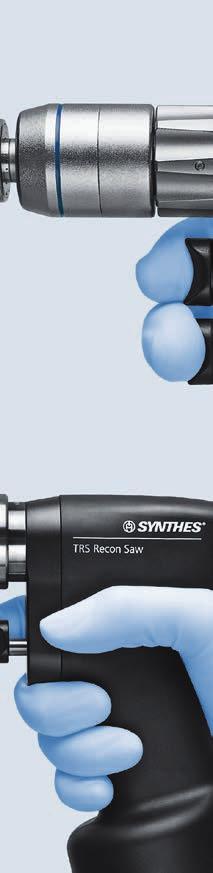
36 TRS Recon Sagittal Saw Power Tool Handpiece ( ) 1 Saw blade screw coupling 2 Sliding sleeve for positioning saw head 3 Trigger for speed regulation 4 Lid 5 Mode switch (integrated onto lid) Fig. 1 Lid ( ) 1 Mode switch 2 Safety button for mode switch (prevents inad vertent opening of the lid; only press to set to UNLOCK ) 3 UNLOCK position 4 LOCK position 5 SAW position Fig DePuy Synthes Trauma Recon System Instructions for Use
 1 Information button (when pressed, the charge status display and/or service indicator illuminates for a few seconds) 2 Charge status display 3 Service indicator (when LED illuminates the power")
37 Power module ( ) 1 Information button (when pressed, the charge status display and/or service indicator illuminates for a few seconds) 2 Charge status display 3 Service indicator (when LED illuminates the power module immediately must be sent to the nearest Synthes service center) 4 Lever to remove the power module from the handpiece Trauma Recon System Instructions for Use DePuy Synthes 33
38 TRS Recon Sagittal Saw Functions of the Lid for TRS Recon Sagittal Saw Mode switch The mode switch on the lid for TRS Recon Sagittal Saw ( ) can be set to 3 different positions UNLOCK position 2 LOCK position 3 SAW position The lid for TRS Recon Sagittal Saw ( ) only fits onto the TRS Recon Sagittal Saw handpiece ( ). UNLOCK position In this position, the lid can be attached and removed. In all other positions the lid is secured so that it cannot inadvertently disengage during surgery. To position the mode switch to UNLOCK, press the safety button for mode switch (see Fig. 2 on page 34) at the same time. This prevents inadvertent switching of the mode switch to UNLOCK and opening of the handpiece. It is not necessary to press the safety button to turn the mode switch to any other position. LOCK position In this position, the tool is secured and cannot operate. SAW mode This mode is designed for working with the TRS Recon Sagittal Saw. Working in the SAW mode The trigger gradually controls the speed. When the trigger is released, the tool immediately stops. Precautions: When the tool is not in use during the surgery, set the handpiece on its side to ensure that it does not fall over due to instability. Only place the power tool in an upright position on the sterile table to insert/remove attachments and cutting tools. While switching from LOCK to SAW, a trigger delay of 1 2 seconds will occur for reasons of safety. To avoid injuries, the mode switch has to be in LOCK position when inserting/removing cutting tools and when placing the tool down. 33 DePuy Synthes Trauma Recon System Instructions for Use
. Positioning the saw head The saw head can be locked into 8 different positions in 45 increments. Fig.")
39 Working with the TRS Recon Sagittal Saw Operating the TRS Recon Sagittal Saw Turn the mode switch to the SAW position. The single variable-speed trigger allows control of the oscillating frequency. When the trigger is released, the tool immediately stops. (Control elements see page 34). Positioning the saw head The saw head can be locked into 8 different positions in 45 increments. Fig. 1 To set the desired position, pull the sliding sleeve back for positioning the saw head and turn the saw head to the selected position. Release the sliding sleeve. Turn the saw head slightly to the left or to the right. It automatically locks into place once the exact position is found. Precautions: To position the saw head, turn the mode switch on the lid to LOCK. Always position the saw head with the fitted saw blade away from the body in order to avoid injury (Fig. 1). Trauma Recon System Instructions for Use DePuy Synthes 33
40 TRS Recon Sagittal Saw Changing the saw blades Only use original Synthes saw blades. These are optimized to meet the specific requirements of the tool. Generic products can considerably reduce the life time of the system. 1. LOCK the machine. 2. Open the saw blade screw coupling by turning the key ( ) counterclockwise. 3. Lift and remove the saw blade. 4. Insert a new saw blade and move it into the desired position. The saw blade can be locked in eight different positions. 5. Lock the saw blade coupling by turning the key clockwise and make sure that the screw is firmly tightened. Otherwise the screw can loosen during use causing the saw blade to vibrate. Working with the TRS Recon Sagittal Saw Allow the unit to start up before placing it on the bone. Avoid excess pressure on the saw blade so as not to jam it. The best sawing performance is achieved by moving the tool slightly back and forth in the plane of the saw blade so that the blade can go a bit beyond the bone on both sides. Very precise cuts can be made when the saw blade is guided steadily. Imprecise cuts indicate worn saw blades, excessive pressure or jamming of the saw blade due to tilting. Instructions for handling saw blades For best results, Synthes recommends using a new saw blade for each operation. This ensures that the saw blade is optimally sharp and clean. The following risks are associated with used blades: Necrosis caused by excessive heat build-up Infection caused by residue Extended cutting time from poor sawing performance Noise and vibration values can differ significantly when: working with other than typical saw blades sawing vertically working with poorly maintained tools working with saw blades from a different supplier not working in SAW mode Saw blades must be cooled with irrigation liquid to prevent heat necrosis. 33 DePuy Synthes Trauma Recon System Instructions for Use
41 Care and Maintenance General Information Power tools and attachments are frequently exposed to high mechanical loads and shocks during use and should not be expected to last indefinitely. Proper handling and maintenance help extend the useful life of surgical instruments. Frequent reprocessing does not have a great effect on the life of the unit and attachments. Gentle care and maintenance with proper lubrication can substantially increase the reliability and life of the system components. Synthes power tools must be serviced and inspected annually by the original manufacturer or an authorized site. Yearly maintenance will ensure that the equipment maintains the highest standard of performance and will prolong the life of the system. The manufacturer assumes no warranty for damages arising from improper use, neglected or unauthorized servicing of the tool. For more information about Care and Maintenance, please refer to the TRS Care and Maintenance Poster ( ). Precautions: Reprocessing must be performed immediately after each use. Cannulations, unlocking sleeves and other narrow sites require special attention during cleaning. Cleaners with a ph are recommended. The use of cleaners with higher ph-values can depending on the cleaner cause a dissolution of the surface of aluminum and its alloys, plastics or compound materials, they should only be used considering the data regarding material compatibility according to its data sheet. At ph values higher than 11 also the surfaces of stainless steel can be affected. For detailed information about material compatibility, see Material Compatibility of Synthes Instruments in Clinical Processing at Follow the enzymatic cleaner or detergent manufacturer s instructions for use for correct dilution concentration, temperature, exposure time and water quality. If temperature and time are not provided, follow Synthes recommendations. Devices should be cleaned in a fresh, newly-made solution. Detergents used on the products will contact the following materials: stainless steel, aluminum, plastic, and rubber seals. Synthes recommends using new sterile cutting tools for each operation. Refer to Clinical Processing of Cutting Tools for detailed clinical processing instructions. Do not immerse the handpiece, power module, lid or attachments in aqueous solutions or in an ultrasonic bath. Do not use pressurized water as this will cause damage to the system. Synthes recommends using new sterile cutting tools for each operation. Refer to Clinical Pro cessing of Cutting Tools ( ) for detailed clinical processing instructions. Unusual Transmissible Pathogens Surgical patients identified as at-risk for Creutzfeldt-Jakob disease (CJD) and related infections should be treated with single-use instruments. Dispose of instruments used or suspected of use on a patient with CJD after surgery and/or follow current national recommendations. Note The clinical processing instructions provided have been validated by Synthes for preparing a non-sterile Synthes medical device; this instruction is provided in accordance with ISO 17664:2004 and ANSI/AAMI ST81:2004. Consult national regulations and guidelines for additional information. Compliance is additionally required with internal hospital policies and procedures and recommendations of manufacturers of detergents, disinfectants, and any clinical processing equipment. Cleaning Agent Information: Synthes used the following cleaning agents during validation of these reprocessing recommendations. These cleaning agents are not listed in preference to other available cleaning agents which may perform satisfactorily neutral ph enzymatic detergents (e. g. Prolystica 2X Concentrate Enzymatic Cleaner). It remains the responsibility of the processor to ensure that the processing performed achieves the desired result using the appropriate properly installed, maintained and validated equipment, materials and personnel in the processing unit. Any deviation by the processor from the instructions provided should be properly evaluated for effectiveness and potential adverse consequences. Trauma Recon System Instructions for Use DePuy Synthes 33

 after each use. Precaution: The power module must not be washed, rinsed, disinfected or sterilized.")
 of TRS Recon Sagittal Saw (05.001.")
 manual cleaning or b) automated cleaning with manual pre-cleaning.")
42 Care and Maintenance Preparation prior to Cleaning Disassemble Disassemble device if applicable, make sure that all movable parts are open and remove the power module from the handpiece. Power modules and charger may be wiped with a cloth (Figs 1 and 2). Return power modules to Universal Battery Charger II ( ) after each use. Precaution: The power module must not be washed, rinsed, disinfected or sterilized. Do not immerse the handpiece, lid or attachments in aqueous solutions or in an ultrasonic bath as this could decrease the service life of the system. Figure 1 Screw coupling (Fig. 4) of TRS Recon Sagittal Saw ( ) and Sagittal Saw Attachment long for TRS Battery Modular ( ) need to be removed for separate cleaning. Power tools and attachments may be processed using a) manual cleaning or b) automated cleaning with manual pre-cleaning. Figure 2 Note: Clean all movable parts in opened position. Figure 3 Figure 4 44 DePuy Synthes Trauma Recon System Instructions for Use
43 a) Manual Cleaning Instruction 1 Remove debris Rinse device under running cold tap water for a minimum of 2 minutes. Use a sponge, soft lint-free cloth and/or softbristled brush to assist in the removal of gross soil and debris. Clean all cannulations (handpieces and attachments) with the cleaning brush ( ). 2 Manipulate moving parts Manipulate all moving parts such as the triggers, release sleeves for attachments, mode switch, etc. under running cold tap water to loosen and remove gross debris. Notes: Do not use pointed objects for cleaning. Brushes and other cleaning tools shall be either single use items or, if reusable, be decontaminated at least daily using a solution as detailed in section 3. Spray and wipe. Brushes shall be inspected before daily use and discarded if they have degraded to the point where they may scratch instrument surfaces or be ineffective due to worn or missing bristles. (310 mm) (78 mm) (55 mm) Cleaning brush ( ) (B 4.7 mm) Trauma Recon System Instructions for Use DePuy Synthes 41


44 Care and Maintenance 3 Spray with solution Spray and wipe device using a enzymatic cleaner or detergent solution or foam spay for a minimum of 2 minutes. Follow the enzymatic cleaner or detergent manufacturer s instructions for use for correct temperature, water quality and concentrations/dilution. 4 Rinse with tap water Rinse device with cold tap water for a minimum of 2 minutes. Use a syringe or pipette to flush lumens and channels. 44 DePuy Synthes Trauma Recon System Instructions for Use

45 5 Clean with detergent Clean device manually under running water using an enzymatic cleaner or detergent for a minimum of 5 minutes. Manipulate all moving parts under running water. Use a soft-bristled brush and/or soft lint-free cloth to remove all visible soil and debris. Clean screw coupling for TRS Recon Sagittal Saw ( ) and Sagittal Saw Attachment long for TRS Battery Modular ( ) ultrasonically for a minimum of 15 minutes at 40 C. Follow the enzymatic cleaner or detergent manufacturer s instructions for use for correct temperature, water quality and concentrations/dilution. 6 Rinse with tap water Rinse device thoroughly using running cool to lukewarm water for a minimum of 2 minutes. Use a syringe or pipette to flush lumens and channels. Actuate joints, handles and other movable device feature in order to rinse thoroughly under running water. 7 Visually inspect device Inspect the cannulations, coupling sleeves, etc for visible soil. Repeat Steps 1 6 until no visible soil remains. Trauma Recon System Instructions for Use DePuy Synthes 44


46 Care and Maintenance 8 Finale rinse with de-ionized/purified water Finale rinse with de-ionized or purified water for a minimum of 2 minutes. 9 Dry Dry device using a soft lint-free cloth or clean compressed air. 44 DePuy Synthes Trauma Recon System Instructions for Use
 have not been validated by Synthes.")
47 b) Mechanical /Automated Cleaning Instruction with Manual Pre-cleaning Important Manual pre-cleaning prior to mechanical/automated cleaning/disinfection is important to ensure cannulations and other difficult to access areas are clean. Alternative cleaning/disinfection procedures other than in the procedure described below (including manual pre-cleaning) have not been validated by Synthes. 1 Remove debris Rinse device under running cold tap water for a minimum of 2 minutes. Use a sponge, soft lint-free cloth and/or softbristled brush to assist in the removal of gross soil and debris. Clean all cannulations (handpieces and attachments) with the cleaning brush ( ). 2 Manipulate moving parts Manipulate all moving parts such as the triggers, release sleeves for attachments, mode switch, etc. under running cold tap water to loosen and remove gross debris. Notes: Do not use pointed objects for cleaning. Brushes and other cleaning tools shall be either single use items or, if reusable, be decontaminated at least daily using a solution as detailed in section 3. Spray and wipe. Brushes shall be inspected before daily use and discarded if they have degraded to the point where they may scratch instrument surfaces or be ineffective due to worn or missing bristles. (310 mm) (78 mm) (55 mm) Cleaning brush ( ) (B 4.7 mm) Trauma Recon System Instructions for Use DePuy Synthes 45

48 Care and Maintenance 3 Spray with solution Spray and wipe device using a enzymatic cleaner or detergent solution or foam spay for a minimum of 2 minutes. Follow the enzymatic cleaner or detergent manufacturer s instructions for use for correct temperature, water quality and concentrations/dilution. 4 Clean with detergent Clean device manually under running water using a enzymatic cleaner or detergent for a minimum of 5 minutes. Manipulate all moving parts under running water. Use a soft-bristled brush and/or soft lint-free cloth to remove all visible soil and debris. Clean screw coupling for TRS Recon Sagittal Saw ( ) and Sagittal Saw Attachment long for TRS Battery Modular ( ) ultrasonically for a minimum of 15 minutes at 40 C. Follow the enzymatic cleaner or detergent manufacturer s instructions for use for correct temperature, water quality and concentrations/dilution. 44 DePuy Synthes Trauma Recon System Instructions for Use
49 5 Rinse with tap water Rinse device thoroughly using running cool to lukewarm water for a minimum of 2 minutes. Use a syringe or pipette to flush lumens and channels. Actuate joints, handles and other movable device feature in order to rinse thoroughly under running water. 6 Visually inspect device Repeat Steps 1 5 until no visible soil remains. Manual pre-cleaning as described above must be followed by the mechanical/automated cleaning procedure. Trauma Recon System Instructions for Use DePuy Synthes 44
, if applicable, are positioned vertically, i.e., in an upright position as shown. This will ensure that the water can flow off any surfaces.")
50 Care and Maintenance 7 Load washing basket Place devices in the specially designed tray for machine washing supplied by Synthes ( ). Ensure that all cannulations (handpiece and attachments), if applicable, are positioned vertically, i.e., in an upright position as shown. This will ensure that the water can flow off any surfaces. Damage due to improper reprocessing is not covered by the warranty. Notes: A lid ( ) is available for the washing basket. This can be used for sterilization, but is not required for machine washing. Do not wash the system in the Synthes Vario Cases ( , ). Dimensions of the Washing Basket (Length Width Height): Washing Basket without Lid: mm Washing Basket with Lid: mm 8 Automated cleaning cycle parameters Note: The washer/disinfector should fulfill requirements specified in ISO Step Duration (minimum) Cleaning Instructions Rinse 2 minutes Cold tap water Pre-wash 1 minutes Warm water ( 40 C); use detergent Cleaning 2 minutes Warm water ( 45 C); use detergent Rinse 5 minutes Rinse with de-ionized (DI) or purified water (PURW) Thermal disinfection 5 minutes Hot DI water, 93 C Dry 40 minutes 90 C 44 DePuy Synthes Trauma Recon System Instructions for Use
51 9 Inspect device Remove all devices from washing basket. Inspect the cannulations, coupling sleeves, etc. for visible soil. If necessary, repeat the manual pre-clean/automated cleaning cycle. Especially check sealings in the TRS lids and for damage after cleaning. Devices must be properly lubricated and regularly send to be serviced (at least once per year). Confirm that all parts are completely dry. Precaution: Mechanical cleaning is an additional stress for power equipment, especially for seals and bearings. Therefore, devices must be properly lubri cated after automated cleaning. Furthermore, the device must be serviced at least once per year as specified under the section Repair and Technical Services on page 52. Trauma Recon System Instructions for Use DePuy Synthes 44


52 Care and Maintenance Maintenance and Lubrication The power tools and attachments should be regularly lubricated to ensure a long service life and smooth operation. It is recommended that the accessible moving parts of the handpieces, the lids and attachments are lubricated with 1 2 drops of Synthes special oil ( ) and distribute the oil by moving the components. Wipe off excess oil with a cloth. The following individual parts must be lubricated: For detailed information please refer to the TRS Care and Maintenance Poster ( ) Handpieces and lids Trigger shafts Release sleeve for attachments/attachment coupling Sliding sleeve for positioning saw head Safety button for mode switch The connection of the power module in the inside of the handpiece does not have to be lubricated. Also the inner side of the lid does not have to be lubricated. Attachments All moving parts of all attachments. Exception: the Radiolucent Drive ( ) does not have to be lubricated. 55 DePuy Synthes Trauma Recon System Instructions for Use
Trauma Recon System (TRS). Battery-driven Power System designed for traumatology and arthroplasty.
. Battery-driven Power System designed for traumatology and arthroplasty.") Trauma Recon System (TRS). Battery-driven Power System designed for traumatology and arthroplasty. Instructions for Use This publication is not intended for distribution in the USA. Instruments and implants
Trauma Recon System (TRS). Battery-driven Power System designed for traumatology and arthroplasty. Instructions for Use This publication is not intended for distribution in the USA. Instruments and implants
Instructions for Use. Air Power Line II. Power tools for endoprosthetics and traumatology.
 Instructions for Use Air Power Line II. Power tools for endoprosthetics and traumatology. Contents Introduction General information 3 Startup of the Air Power Line system 5 Working with the Air Power
User s Manual. Small Electric Drive. Compact and powerful system for use in hand and foot surgery.
 User s Manual Small Electric Drive. Compact and powerful system for use in hand and foot surgery. Table of Contents Introduction General Information 1 Consoles General Description 4 Set-up 6 Small Electric
Air-driven Universal Power Tool System for Traumatology, Endoprosthetics, and Spine. Compact Air Drive II. Instructions for Use
 Air-driven Universal Power Tool System for Traumatology, Endoprosthetics, and Spine Compact Air Drive II Instructions for Use Contents Introduction General Information 2 Explanation of symbols used 4
ComPact Air Drive II USER S MANUAL
 ComPact Air Drive II USER S MANUAL R Original Instruments and Implants of the Association for the Study of Internal Fixation AO ASIF TABLE OF CONTENTS Page ComPact Air Drive II Specifications... 2 Attachments...
AS Medizintechnik GmbH Sattlerstrasse 15, Tuttlingen, Germany Tel 07461/ Fax 07461/
 General Information Use The Air drill System is a pneumatic powered system used for many applications orthopedic and trauma surgery. To ensure proper operation of the air drill, use only original attachment
Table of Contents. English
 OM-E0799E 000 English Thank you for purchasing VIVA ace Motor Kit. Please read this Operation Manual and the VIVA ace Basic Set Operation Manual carefully before use for operating instructions and care
Suits all KPF849 models
 Kambrook - Australia Ground Floor, Suite 2, 170-180 Bourke Rd Alexandria NSW 2015, Australia Locked Bag 2000 Botany NSW 1455 Customer Service Line 1300 139 798 Customer Service Fax 1800 621 337 www.kambrook.com.au
Instructions for Use Spinal Punches IFU
 Indications for use Spinal punches are manually operated instruments indicated for cutting or biting bone during surgery involving the skull or spinal column. Contraindiciations Instruments should not
Cascade Comfort Bathing Systems with Aqua-Aire Safe Operation & Daily Maintenance Instructions
 Cascade Comfort Bathing Systems with Aqua-Aire Safe Operation & Daily Maintenance Instructions PENNER PATIENT CARE, INC Box 523 / 101 Grant St. Aurora, NE 68818 560750 Revision A 12/11/15 1-866-PENNERS
Instructions for use. BA Optima. Air motors BA602 (BA640081) BA604 (BA640060)
 BA604 (BA640060)") Instructions for use BA Optima Air motors BA602 (BA640081) BA604 (BA640060) Contents 1. Introduction....3 5 2. Safety notes...6 9 3. Product description... 10 11 4. Operation... 12 13 Assembly/Removal,
Instructions for use BA Optima Air motors BA602 (BA640081) BA604 (BA640060) Contents 1. Introduction....3 5 2. Safety notes...6 9 3. Product description... 10 11 4. Operation... 12 13 Assembly/Removal,
Application Tooling Specification Sheet
 Modular Crimp Head Order No. 63827-5470 Application Tooling Specification Sheet TYPE 4A Hand Crimp Tool Order No. 63827-5400 FEATURES A full cycle ratcheting hand tool ensures complete crimps Ergonomically
your floor machine. As a shipper, we are unable to act upon any claim for concealed damage. You must originate any claim within 5 days of delivery.
 SAFETY, OPERATION AND MANUAL HIGH, DUO & VARIABLE SPEED FLOOR MACHINE This unit is intended for commercial use. READ & FOLLOW ALL, WARNINGS & CAUTIONS BEFORE USING THIS FLOOR MACHINE This floor machine
HW-17 Record Cleaning Machine Setup and Instruction Manual
 HW-17 Record Cleaning Machine Setup and Instruction Manual VPI Industries, Inc., 77 Cliffwood Ave. #3B, Cliffwood, NJ 07721 Phone: 732-583-6895, Email: Sales@vpiindustries.com http://www.vpiindustries.com
ENGLISH (Original instructions) INSTRUCTION MANUAL. Demolition Hammer HM0810TA DOUBLE INSULATION. IMPORTANT: Read Before Using.
 INSTRUCTION MANUAL. Demolition Hammer HM0810TA DOUBLE INSULATION. IMPORTANT: Read Before Using.") ENGLISH (Original instructions) INSTRUCTION MANUAL Demolition Hammer HM080TA 00079 DOUBLE INSULATION IMPORTANT: Read Before Using. ENGLISH (Original instructions) SPECIFICATIONS Model HM080TA Blows per
ENGLISH (Original instructions) INSTRUCTION MANUAL Demolition Hammer HM080TA 00079 DOUBLE INSULATION IMPORTANT: Read Before Using. ENGLISH (Original instructions) SPECIFICATIONS Model HM080TA Blows per
Instruction manual. Please keep safe for future reference
 16in / 40cm Eco Pedestal Fan with 30W DC motor, Digital Display & Remote Control Model: SFDC-40101RC WARNING: Keep Batteries Out of Reach of Children 1. Swallowing may lead to serious injury in as little
WARNING: Warns of health hazards and identifies possible risks of injury. CAUTION: Indicates possible dangers to the machine or other objects.
 VBT3ASV USER GUIDE SAFETY INFORMATION About this user guide Read this user guide completely before using the machine. Keep this user guide for reference. If you pass your machine on to third parties, it
EMAX 2 PLUS SYSTEM High speed performance and power in a variety of applications
 EMAX 2 PLUS SYSTEM High speed performance and power in a variety of applications This publication is not intended for distribution in the USA. USER S MANUAL TABLE OF CONTENTS INTRODUCTION Anspach Electric
Instruction manual EN
 Instruction manual EN Contents Introduction... 3 Keyboard /Display... 4 1. Horizontal Operation... 5 2. Rotation Speed... 5 3. Slope in Manual Mode... 5 4. Mask Mode... 6 5. Setting the Levelling Precision
ELECTRIC DRILL INSTRUCTIONS. Item #21285
 ELECTRIC DRILL INSTRUCTIONS Item #21285 The EASTWOOD ELECTRIC DRILL is great for use on virtually all metals including steel, aluminum, brass and more. The powerful 6.3 Amp motor and 1/2 capacity chuck
40cm Pedestal Fan with Remote Control
 Instruction Manual 40cm Pedestal Fan with Remote Control Model: HF40BRG READ AND SAVE THESE INSTRUCTIONS Please read and follow the instructions in this user manual even if you feel you are familiar with
Garment Steamer Model SC620
 OWNER S MANUAL Garment Steamer Model SC620 For information or assistance: EURO-PRO Corporation 178 West Service Rd. Champlain, NY 12919 1-800-798-7398 www.euro-pro.com IMPORTANT SAFETY INSTRUCTIONS When
Surgical Technique. Limited Market Release. Limited Market Release
 Surgical Technique 1 Surgical Technique for the EVOS MINI Plating System Contents Product overview...3 Indications...3 Plating options...4 Screw options...5 Plate selection...6 Plate modification...6 Plate
Instruction Manual. Self-Leveling Rotary Laser Level Model Nos and
 Self-Leveling Rotary Laser Level Model Nos. 40-6515 and 40-6516 Instruction Manual Congratulations on your choice of this Self-Leveling Rotary Laser Level. We suggest you read this instruction manual thoroughly
ATD /8 Electric Drill
 ATD-10538 3/8 Electric Drill Tool specifications: Rated Voltage: (V) 120 Rated Frequency: (Hz) 60 Rated current: (A) 3.3 No-load Speed: (RPM) 0-2700 Speed Selection: Yes Right/Left Rotation: Yes Chuck
150MM ELECTRIC EARTH BORER
 150MM ELECTRIC EARTH BORER MODEL NO: CEA150 PART NO: 3400997 OPERATING & MAINTENANCE INSTRUCTIONS GC0915 INTRODUCTION Thank you for purchasing this CLARKE Electric Earth Borer designed for boring holes
BL250. Pulse Blender OWNER S GUIDE
 BL250 OWNER S GUIDE Pulse Blender 1-877-646-5288 IMPORTANT SAFETY INSTRUCTIONS For Household Use Only WHEN USING ELECTRICAL APPLIANCES, BASIC SAFETY PRECAUTIONS SHOULD ALWAYS BE FOLLOWED, INCLUDING THE
VISION H. Instruction manual
 VISION H Instruction manual EN Contents Introduction.. 3 Keyboard / Display... 4 1. Horizontal Operation.. 4 2. Tilt Function... 4 3. Power Supply of Laser.... 5 4. Detector............. 6 TE 6... 7 TE
Dental Unit User's Guide
 Dental Unit User's Guide MDD 93/42/EEC May 1999 8200590 Quint-7000 User's Guide We reserve the right to make changes. Manufactured by: FINNDENT OY Teollisuustie 5 FIN-07230 MONNINKYLÄ Tel. +358 19 5221500
One-Touch Dispense. Multi-temp selections. 208 F For tea, coffee, instant noodle. 194 F Keep warm around 194 F. 176 F Keep warm around 176 F.
 Instruction Manual Automatic Dispensing Hot Water Pot with Multi-temperature Function Automatic Dispensing One-Touch Dispense FEATURES Reboil Function 5 Temperature Settings Image Of SP-5016 208 F For
Bagless upright. Vax Careline (UK) (ROI) vax.co.uk VS-19EC. Vax model number:
 (ROI) vax.co.uk VS-19EC. Vax model number:") Vax Careline (UK) 0844 412 8455 Bagless upright Vax model number: VS-19EC instruction manual vax.co.uk Please read carefully before using this cleaner. Always fully extend the mains cable before use. Retain
Vax Careline (UK) 0844 412 8455 Bagless upright Vax model number: VS-19EC instruction manual vax.co.uk Please read carefully before using this cleaner. Always fully extend the mains cable before use. Retain
GLC3630L.
 www.blackanddecker.com.au www.blackanddecker.co.nz GLC3630L A B C D E 2 F G H I J K L 3 M N O P Q 4 R (Original instructions) ENGLISH Intended use Your BLACK+DECKER trimmer has been designed for trimming
Manual. Belt Sander BSL 115/E. ProxxonTools.com
 ProxxonTools.com Belt Sander BSL 115/E Manual 3080767 Conforms to ANSI/UL 60745-1 ANSI/UL 60745-2-4 Certified to CAN/CSA-C22.2 No. 60745-1-04 CAN/CSA-C22.2 No. 60745-2-4-04 Fig. 1 Fig. 2 Fig. 3 Fig. 4
X99 Series. Dental Handpiece. Instruction For Use
 X99 Series Dental Handpiece Instruction For Use 0413 Table of Contents Symbols... 2 Introduction... 3-4 Before Use... 5 Product description... 6 Technical Specifications... 7 Operation... 8-11 Hygienic
Bliss Box Former Troubleshooting. 6.1 Troubleshooting Chart. Troubleshooting INTRODUCTION SAFETY PROCEDURES
 6.0 Bliss Box Former 1.0 INTRODUCTION Table 6-1 provides a logical sequence of tests that are designed to isolate problems with the Bliss Box Former machines. This table includes a list of probable causes
Power-Spin. Drain Cleaner Operator s Manual
 Drain Cleaner Operator s Manual Power-Spin! Read this Operator s Man ual carefully before using this tool. Failure to understand and follow the contents of this manual may result in electrical shock, fire
ENGLISH (Original instructions) INSTRUCTION MANUAL. Power Mixer UT2204 DOUBLE INSULATION. IMPORTANT: Read Before Using.
 INSTRUCTION MANUAL. Power Mixer UT2204 DOUBLE INSULATION. IMPORTANT: Read Before Using.") ENGLISH (Original instructions) INSTRUCTION MANUAL Power Mixer UT04 0078 DOUBLE INSULATION IMPORTANT: Read Before Using. ENGLISH (Original instructions) SPECIFICATIONS Model UT04 No load speed (min - )
ENGLISH (Original instructions) INSTRUCTION MANUAL Power Mixer UT04 0078 DOUBLE INSULATION IMPORTANT: Read Before Using. ENGLISH (Original instructions) SPECIFICATIONS Model UT04 No load speed (min - )
Penner Stationary Patient Lift Safe Operation & Daily Maintenance Instructions
 Penner Stationary Patient Lift Safe Operation & Daily Maintenance Instructions PENNER PATIENT CARE, INC Box 523 / 102 Grant St. Aurora, NE 68818 350751 Rev B 09/15/2006 1-866-PENNERS 1-866-736-6377 1-800-732-0717
Bagless upright vacuum
 U89 U90 & U91-P2 Power 2 Series User Guide V2.0:U90-P2 User Guide 13/08/2010 11:44 Page 1 Vax Careline: (UK) 0844 412 8455 (ROI) 1-800 928 308 Bagless upright vacuum Vax model number: U91-P2 Series U90-P2
Instruction Manual. Self-Leveling Rotary Laser Level Model No &
 3180H_Manuals 2/12/10 11:12 AM Page 1 Self-Leveling Rotary Laser Level Model No. 40-6527 & 40-6532 Instruction Manual Congratulations on your choice of this Self-Leveling Rotary Laser Level. We suggest
Operator s Manual. The Bullet Blender 50 BB50-AU, BB50-DX. Contents. Congratulations!
 Operator s Manual The Bullet Blender 50 BB50-AU, BB50-DX Congratulations! Congratulations on your purchase of a Bullet Blender 50 by Next Advance, Inc., for mixing, lysing, disrupting, and homogenizing
CONSTANT SUCTION UNIT
 CONSTANT SUCTION UNIT OPERATOR/MAINTENANCE M A N U A L Squire-Cogswell/Aeros Instruments Inc 1111 Lakeside Drive Gurnee, IL 60031-4099 1-800-662-5822/847-855-0800 Fax: 847-855-6218 www.aerosinstruments.com
EL400 OPERATION MANUAL
 All Titanium Body Micromotor System EL400 OPERATION MANUAL 40,000min -1 (rpm) OM-E0078E Rev.3 Please read this operation manual carefully before use and keep for future reference. Classification of equipment
POWER JUICER ELITE
 Operating Manual Contents 4 5 6 7 10 11 13 14 Important Safety Information Helpful Hints Parts/Main Unit Assembly/Main Unit Assembly/E-Z Loader Attachment Disassembly/Main Unit Cleaning Your Power Juicer
Instructions for Use. Technical and General 2 Ablion Pl. London W6 0QT, United Kingdom Rev. A. European Representative
 O B T U R A T I O N S Y S T E M Instructions for Use Manufactured for SybronEndo 1332 S. Lone Hill Avenue, Glendora, CA 91740 U.S.A. 714.516.7979 SybronEndo.com MADE IN KOREA META BIOMED CO., LTD. 270,
SERVICE PROCEDURES. Mattress 2 Pipe Overlay or Replacement
 Mattress 2 Pipe Overlay or Replacement Contents 2 pipe Mattress Mattress 3 Air Leak Test 4 Air Cell Replacement 5 Air Pipe Connector Replacement 6 Troubleshooting 7 Safety 9 Care & Cleaning 10 Definition
READ AND SAVE THESE INSTRUCTIONS
 Instruction Manual 45cm Pedestal Fan Model: PED45CG READ AND SAVE THESE INSTRUCTIONS Please read and follow the instructions in this user manual even if you feel you are familiar with the product, and
Cable Drum Machine. Operation Manual 110ES SERIES. Cleans 1 1/4" to 3" lines up to 25'
 Cable Drum Machine Operation Manual 110ES SERIES Cleans 1 1/4" to 3" lines up to 25' Used For: Sinks, Showers &Tub Drains WARNING - Read All Instructions, When Using Electric Tools, Basic Safety Precautions
ULTRASONIC HUMIDIFIER
 To Buy: Visit www.sylvane.com or call (800) 934-9194 For Product Support: Contact Sunpentown at 1-800-330-0388 ULTRASONIC HUMIDIFIER [ADORABLE MONKEY] To prolong the life of this humidifier, using distilled
OWNER S GUIDE SV
 OWNER S GUIDE SV1100 WARNINGS IMPORTANT SAFETY INSTRUCTIONS For Household Use Only WHEN USING YOUR SHARK CORDLESS VACUUM, BASIC SAFETY PRECAUTIONS SHOULD ALWAYS BE FOLLOWED, INCLUDING THE FOLLOWING: READ
OWNER S GUIDE SV
 OWNER S GUIDE SV1100 SV1100_ENG_110503_2.indd 1 WARNINGS IMPORTANT SAFETY INSTRUCTIONS For Household Use Only WHEN USING YOUR SHARK CORDLESS VACUUM, BASIC SAFETY PRECAUTIONS SHOULD ALWAYS BE FOLLOWED,
Bagless upright. vax.co.uk. Vax Careline: (UK) (ROI) VS-190 Series. Vax model number: Version 1.1
 (ROI) VS-190 Series. Vax model number: Version 1.1") VS-190 Series User Guide V1.1.qxd:VS-190 User Guide 26/1/11 10:44 Page 1 Vax Careline: (UK) 0844 412 8455 (ROI) 1-800 928 308 Bagless upright Vax model number: VS-190 Series WARNING: This cleaner has a
VS-190 Series User Guide V1.1.qxd:VS-190 User Guide 26/1/11 10:44 Page 1 Vax Careline: (UK) 0844 412 8455 (ROI) 1-800 928 308 Bagless upright Vax model number: VS-190 Series WARNING: This cleaner has a
PS /2 Inch Angle Grinder Assembly & Operating Instructions READ ALL INSTRUCTIONS AND WARNINGS BEFORE USING THIS PRODUCT.
 PS07214 4 1/2 Inch Angle Grinder Assembly & Operating Instructions READ ALL INSTRUCTIONS AND WARNINGS BEFORE USING THIS PRODUCT. This manual provides important information on proper operation & maintenance.
ELECTRIC BODY SAW INSTRUCTIONS. Item #31660
 ELECTRIC BODY SAW INSTRUCTIONS Item #31660 The EASTWOOD ELECTRIC BODY SAW is great for use on virtually all metals including steel, aluminum, brass and more. Cuts wood, fiberglass and other materials with
Instructions for the heat exchanger control system SILVER C RX, RECOnomic, sizes 100/120, RECOsorptic, sizes
 Instructions for the heat exchanger control system SILVER C RX, RECOnomic, sizes 100/120, RECOsorptic, sizes 50-120 1 General The heat exchanger control system is a control system for 380 W step motors
TECHNICAL INFORMATION Touchtronic Clothes Dryers
 TECHNICAL INFORMATION Touchtronic Clothes Dryers Includes: T1302, T1303, T1322, T1329ci T1403 & T1405 2004 Miele This page intentionally left blank. Table of Contents GENERAL INFORMATION A. Warning and
20 High velocity Air
 20 High velocity Air Circulator 66878 Set up and Operating Instructions Distributed exclusively by Harbor Freight Tools. 3491 Mission Oaks Blvd., Camarillo, CA 93011 Visit our website at: http://www.harborfreight.com
Service package PDAD- -SP (en) Assembly instructions d [ ]
![Service package PDAD- -SP (en) Assembly instructions d [ ]](/thumbs/89/100944426.jpg "Service package PDAD- -SP (en) Assembly instructions d [ ]") Service package PDAD- -SP-12000 (en) Assembly instructions 8068819 1701d [8068821] Original instructions Installation and commissioning are to be carried out only by qualified personnel in accordance with
Service package PDAD- -SP-12000 (en) Assembly instructions 8068819 1701d [8068821] Original instructions Installation and commissioning are to be carried out only by qualified personnel in accordance with
Oscillating Belt/Spindle Sander 230V
 Oscillating Belt/Spindle Sander 230V Model no: SM1300 Thank you for purchasing a Sealey product. Manufactured to a high standard, this product will, if used according to these instructions, and properly
Owner s Manual & Safety Instructions
 Owner s Manual & Safety Instructions Save This Manual Keep this manual for the safety warnings and precautions, assembly, operating, inspection, maintenance and cleaning procedures. Write the product s
OPERATIONAL & MAINTENANCE MANUAL
 Security Engineered Machinery Co., Inc OPERATIONAL & MAINTENANCE MANUAL SEM Model 0101 Hard Drive Crusher 110 volt or 220 volt (Serial Numbers 2000 and up) Contents IMPORTANT SAFETY PROCEDURES... 3 INSTALLATION
Translation of the Original Operating Instructions MAB 100 K
 Translation of the Original Operating Instructions MAB 100 K 5 6 4 7 3 2 8 1 9 11 10 General instructions Table of Contents General instructions...3 Safety...5 Components / delivery contents...9 Before
Installation and Operating Instructions DÜRR Regeneration Unit for X-ray developers XR 24, XR24 II, XR 24 Nova, XR 24 Pro
 Installation and Operating Instructions DÜRR Regeneration Unit for X-ray developers XR 24, XR24 II, XR 24 Nova, XR 24 Pro 2006/01 Content Important Information 1. Notes... 3 1.1 CE - Labeling... 3 1.2
kéìíê~=iqd=qìåöëíéå=dêáåçéê= lééê~íáçåë=j~åì~ä=
 NJUMMJVQQJOOQP ïïïk~êåjòçåékåçã kéìíê~iqdlééê~íáçåëj~åì~ä m^dbnlcnm kéìíê~iqdqìåöëíéådêáåçéê lééê~íáçåëj~åì~ä ^o`jwlkbk`lj IfåÅ. OMVNi~ëm~äã~ëaêáîÉpíÉK` `~êäëä~çi`^vomnnjnrrn qéäwtsmkvpnknrmm UMMKVQQKOOQP
Instruction Manual. Alarm Unit For Low Gas Level # Read manual before use! Observe all safety information! Keep manual for future use!
 Mess-, Regel- und Überwachungsgeräte für Haustechnik, Industrie und Umweltschutz Lindenstraße 20 74363 Güglingen Telefon +49 7135-102-0 Service +49 7135-102-211 Telefax +49 7135-102-147 info@afriso.de
MULTIWASH XL OPERATOR S MANUAL & PARTS LIST PFMW18. Save These Instructions
 OPERATOR S MANUAL & PARTS LIST MULTIWASH XL PFMW18 WARNING: OPERATOR MUST READ AND UNDERSTAND THIS MANUAL COMPLETELY BEFORE OPERATING THIS EQUIPMENT. Tacony, Inc., All rights reserved Save These Instructions
Operating instructions
 MA00929301 09/2015 Operating instructions ED10429002 ESYLUX GmbH An der Strusbek 40 22926 Ahrensburg Germany info@esylux.com www.esylux.com 1 Table of contents 1 Using the manual 8 2 Safety instructions
275HVD NON-CONTACT, HIGH VOLTAGE DETECTOR DETECTOR DE ALTA TENSIÓN SIN CONTACTO
 99 Washington Street Melrose, MA 02176 Phone 781-665-1400 Toll Free 1-800-517-8431 Visit us at www.testequipmentdepot.com 275HVD NON-CONTACT, HIGH VOLTAGE DETECTOR DETECTOR DE ALTA TENSIÓN SIN CONTACTO
User Manual. Non-contact Infrared Thermometer.
 User Manual Non-contact Infrared Thermometer www.paryvara.com info@paryvara.com Introduction Thank you for purchasing this Non-contact Infrared Thermometer. Please read the User Manual carefully to ensure
GENERAL 2004 HVAC SYSTEMS. Manual HVAC System - Sorento SPECIFICATIONS. Fig. 1: Air Conditioner Specifications Courtesy of KIA MOTORS AMERICA, INC.
 Fig. 2: Blower & Evaporator Unit Specifications 2004 HVAC SYSTEMS Manual HVAC System - Sorento GENERAL SPECIFICATIONS AIR CONDITIONER Fig. 1: Air Conditioner Specifications BLOWER AND EVAPORATOR UNIT HEATER
Instructions for Use: Endoplus Modular Handle Assemblies, Multi-Use Scissors Inserts, Reusable Inserts
 Modular Slide Lock Handle Assembly 1 Movable Handle 2 Fixed Handle 3 Handle Access For Cleaning 4 Window 5 Handle Screw 6 Keeper 7 Nonconductive Luer Port Cap (shown covering the Luer Port) 8 Shaft Insulation
Replacement Guide: TCRU/ORU Model Name: Pro C901S/Pro C901
 Replacement Guide: TCRU/ORU Model Name: Pro C90S/Pro C90 Read this manual carefully before using this machine and keep it handy for future reference. How to Read This Manual Introduction This manual contains
WELCOME BLUE - NEUTRAL BROWN LIVE GREEN AND YELLOW - EARTH
 Zephyr 16 DC FAN WELCOME Thank you and congratulation for choosing an EcoAir DC Fan to help you improve the air quality within your home. Inside you will find many helpful tips on how to use and maintain
ULTRASONIC HUMIDIFIER With Night Light and Fragrance Diffuser
 To Buy: Visit sylvane.com or call (800) 934-9194 For Product Support: Contact Sunpentown 1-800-330-0388 ULTRASONIC HUMIDIFIER With Night Light and Fragrance Diffuser SU-2550B (Blue) SU-2550P (Pink) SU-2550V
Table of Contents What to Expect with Your Installation. Ceiling Plate. Tools Needed.
 Table of Contents Congratulations on purchasing your new Casablanca ceiling fan! It will provide comfort and performance in your home or office for many years. This installation and operation manual contains
Remote alarm case VENTIremote alarm 10 m WM VENTIremote alarm 30 m WM Device description and instructions for use
 VENTIremote alarm Remote alarm case VENTIremote alarm 10 m WM 27745 VENTIremote alarm 30 m WM 27755 Device description and instructions for use Overview VENTIremote alarm 5 Stand-by indicator 1 Battery
INSTRUCTION MANUAL MODEL: 690E
 1 INSTRUCTION MANUAL ALEKO Drywall Sander MODEL: 690E READ THROUGH CAREFULLY AND UNDERSTAND THESE INSTRUCTIONS BEFORE USE Visit our web site for more great products, parts and accessories: 2 3 4 5 6 Caution!
Get Cleaning... What s your Vax s model number? User Guide. Carpet Washer Vax Careline: AU: NZ:
 User Guide Vax Careline: AU: 1300 361 505 NZ: 0800 800 900 Carpet Washer Get Cleaning... What s your Vax s model number? W8 W8 W0 W0 W0 W W W W W What s your serial number? (Located on the base of the
T R A N S F O R M I N G T E C H N O L O G I E S, L L C O U T S T A N D I N G A L T E R N A T I V E S I N S T A T I C C O N T R O L
 T R A N S F O R M I N G T E C H N O L O G I E S, L L C O U T S T A N D I N G A L T E R N A T I V E S I N S T A T I C C O N T R O L BFN 801 Ionizing Blowers Instruction Manual Contents BFN 801 Description
Digital 7 Square Plate Magnetic Stirrer
 Digital 7 Square (Hotplate) Magnetic Stirrer User Manual MS7-Pro Digital 7 Square Plate Magnetic Stirrer MS7-H550-Pro Digital 7 Square Hotplate Magnetic Stirrer Please read the User Manual carefully before
Autofill wall mounted water. boiler. Getting the best from your water. boiler. Please read and keep these instructions
 Autofill wall mounted water boiler Please read and keep these instructions For Burco wall mounted boilers 76700 (SKU 444448534), 76702 (SKU 444448546), & 76704 (SKU444448548) Getting the best from your
EMAX 2 PLUS AND XMAX CLEANING AND STERILIZATION BASKET. Mechanical/Automated Cleaning and Sterilization Guide in a Variety of Applications
 EMAX 2 PLUS AND XMAX CLEANING AND STERILIZATION BASKET Mechanical/Automated Cleaning and Sterilization Guide in a Variety of Applications TABLE OF CONTENTS MANUAL PRE-CLEANING High Speed Handpieces 2
Operating and Maintenance Instructions
 EATON Germany GmbH Werk Lohmar D-53797 Lohmar Operating and Maintenance Instructions WALFORM Machine Electronically controlled - Conforms to CE MEG-WF385X Status: Sept 2011 MEG-WF385X_Stand Sept 2011 SUITABILITY
Challenge 5 Blade Ped Fan With Remote. Simple Assembly Instructions - Please keep for future reference FS40-9HRA
 Challenge 5 Blade Ped Fan With Remote Simple Assembly Instructions - Please keep for future reference FS40-9HRA IMPORTANT SAFETY INSTRUCTIONS Read all instructions before use and keep for future reference.
CAR-MON DUST COLLECTORS SERIES 207, 2410, 3015
 INSTALLATION-OPERATION-MAINTENANCE CAR-MON DUST COLLECTORS SERIES 207, 2410, 3015 TEFC 3 phase motor Outlet duct Fan wheel housing Inlet duct connection After filter transition Optional after filter unit
Here is what comes in your box:
 Here is what comes in your box: We recommend that you pull everything out of the box and lay it out. We have grouped the drawn components below with the hardware you ll need for those parts. The screws
(3 plastic wire connectors,blade balancing kit, 2 extra mounting screws #10-32 for outlet box.)
") Excel Lighting & Manufacturing Ltd. Lifetime Limited Warranty Excel Lighting & Manufacturing Ltd. Warrants the fan motor to be free from defects in workmanship and material present at time of shipment
Excel Lighting & Manufacturing Ltd. Lifetime Limited Warranty Excel Lighting & Manufacturing Ltd. Warrants the fan motor to be free from defects in workmanship and material present at time of shipment
K Operating Instructions. Before first use of the unit read these operating instructions and act in accordance with them.
 K 1.100 Operating Instructions Before first use of the unit read these operating instructions and act in accordance with them. www.kaercher.com/register-and-win 59651430 (10/13) Contents General information..............
INSTRUCTIONS. OJ-DV-Relay-Module. OJ Drives A DRIVES PROGRAMME DEDICATED TO VENTILATION SOLUTIONS. Optional module for OJ-DV motor controller
 INSTRUCTIONS OJ-DV-Relay-Module 67439B 10/16 (OSH) 016 OJ Electronics A/S Optional module for OJ-DV motor controller OJ Drives A DRIVES PROGRAMME DEDICATED TO VENTILATION SOLUTIONS Contents 1. Product
(The chances are you re never going to read me) Owner s Manual. Model S10E.
 Owner s Manual. Model S10E.") (The chances are you re never going to read me) Owner s Manual Model S10E www.simplicityvac.com 1 Contents Getting Started Important Safety Instructions 2 Polarization Instructions 3 State of California
(The chances are you re never going to read me) Owner s Manual Model S10E www.simplicityvac.com 1 Contents Getting Started Important Safety Instructions 2 Polarization Instructions 3 State of California
Model number: ATF305 OPERATING MANUAL. 1761_Multi_Pro_Powerfloor_Manual_aw.indd 1 21/08/ :54
 Model number: ATF305 OPERATING MANUAL 1761_Multi_Pro_Powerfloor_Manual_aw.indd 1 21/08/2017 09:54 2 IMPORTANT SAFEGUARDS: IMPORTANT: READ ALL INSTRUCTIONS BEFORE USE. RETAIN INSTRUCTIONS FOR FUTURE REFERENCE.
LC Series - Light Commercial Pump Station Installation and Operation Manual
 LC Series - Light Commercial Pump Station Installation and Operation Manual Please keep this manual with the pump station Content Rain Bird LC Series Overview... Safety Instruction... Operation... 3 Pump
Flexible Nasopharyngoscope. Operator Manual. Manufactured by Henke-Sass, Wolf Distributed by Anthony Products, Inc.
 Flexible Nasopharyngoscope Operator Manual Manufactured by Henke-Sass, Wolf Distributed by Anthony Products, Inc. 1. Introduction The flexible nasopharyngoscope is sold in unsterile condition as a reusable
USER MANUAL AND TECHNICAL MANUAL
 USER MANUAL AND TECHNICAL MANUAL Kanmed Universal Warming Cabinets Kanmed Blanket Warming Cabinets Kanmed Combination Cabinet GE-2300-070 / 4 2014-05-12 NOTE: This manual contains important information
MODEL 7000 SUCTION UNIT
 MODEL 7000 SUCTION UNIT OPERATOR S MANUAL Caution Federal law restricts this device to sale by or on order of a physician, or any other practitioner licensed by the law of the State in which he practices
IMPORTANT SAFETY INSTRUCTIONS
 Power Shovel Form No. 3362-567 Rev A Model No. 38361 Serial No. 310000001 and Up Operator's Manual If you have questions or problems, call toll free 1-800-808-2963 (US) or 1-800-208-3072 (Canada) before
Coffee Machine Zia series
 Coffee Machine CoEx Brewer - Freshbrew EN Picture: Filename: Zia-6000_9CND_UserManual_5DUCNP20a_EN_v01-02.docx Disclaimer Manufacturer: Although this user manual has been put together with the utmost care,
Drywall Screwdriver INSTRUCTION MANUAL
 ENGLISH (Original instructions) INSTRUCTION MANUAL Drywall Screwdriver 68 00603 DOUBLE INSULATION WARNING: For your personal safety, READ and UNDERSTAND before using. SAVE THESE INSTRUCTIONS FOR FUTURE
Instruction Manual. For All Corning Hot Plates, Stirrers, Stirrer/Hot Plates with Digital Displays, and External Temperature Controller (6795PR)
") Instruction Manual For All Corning Hot Plates, Stirrers, Stirrer/Hot Plates with Digital Displays, and External Temperature Controller (6795PR) Corning Cat. No. 230V 230V Model No. Product Top Plate Size
Instruction Manual For All Corning Hot Plates, Stirrers, Stirrer/Hot Plates with Digital Displays, and External Temperature Controller (6795PR) Corning Cat. No. 230V 230V Model No. Product Top Plate Size
5KHB3583 W A_01_EN_Final4.indd 1 12/11/12 1:34 PM
 5KHB3583 Cordless Hand Blender INSTRUCTIONS Table of Contents Hand blender SAFETY Important safeguards... 6 Electrical requirements... 7 Electrical equipment waste disposal... 7 Disposing of KitchenAid