ST 53.1 User s manual
|
|
|
- Donna Casey
- 6 years ago
- Views:
Transcription


1 Tech - 1 -
2 ST 53.1 User s manual Table of contents I. Safety... 3 II. Description... 4 III. Installation... 4 IV. Operating the Controller... 6 IV.a) Principle of Operation... 6 IV.b) Control... 6 V. Controller Operation Modes... 7 V.a) Mode ECO PLUS... 7 V.b) Mode ECO... 7 V.c) Manual Operation... 7 V.d) Compressor Failure... 8 V.e) Anti-Legionella Mode... 8 V.f) Mode STOP... 8 V.g) Mode PARTY... 8 V.h) System Failure... 8 VI. Main Menu... 9 V.a) Party Mode... 9 V.b) LEGIONELLA Mode (Thermal Disinfection)... 9 V.c) Adjusting Current Time V.d) Setting Days of the Week V.e) Tank Pre-Set Temperature V.f) Tank Anti-Freeze V.g) Weekly Control V.h) Adjusting the Weekly Control V.i) Circulation Pump V.j) Information on Maintenance and Version V.k) Access Protection V.l) Protection Delay V.m) Language Selection VII. Servicing Settings VI.a) Manual Operation VI.b) Minimum Working Temperature VI.c) Heater Operation Below Minimum Temperature V.d) Additional Heat Source Parameters of Solar Collector Parameters of Additional Source V.e) Displaying Additional Temperatures V.f) Rozmrażanie parownika V.g) Tank Pre-Set Temperature Hysteresis V.h) Threshold Temperature ECO ECO PLUS V.i) System Protection V.j) Emergency Temperature V.k) Compressor Delay V.l) LEGIONELLA Function Temperature V.m) LEGIONELLA Function Duration V.n) LEGIONELLA Function Maximum Duration V.o) LEGIONELLA Function Reminder V.p) Adjusting Servicing Telephone Number V.r) Delete Control Temperature Alarm V.s) Adjusting Access Code V.t) Factory Settings VIII. Standby Mode IX. Protections X. Maintenance Technical data

3 Tech I. Safety Before using the device for the first time the user should read the following regulations carefully. Not obeying the rules included in this manual may lead to personal injuries and device damage. The user's manual should be stored carefully. In order to avoid accidents and errors it should be ensured that every person using the device has familiarized themselves with the principle of operation as well as security functions of the device. If the device is sold or put in a different place make sure that the user's manual is there with the device so that any potential user has access to essential information about using the device and safety. The manufacturer does not accept responsibility for any injuries or damage resulting from negligence; therefore, users are obliged to take the necessary safety measures listed in this manual to protect their lives and property. WARNING High voltage. Make sure the regulator is disconnected from the mains before performing any activities involving the power supply (plugging cables, installing the device etc.) The device should be installed by a qualified electrician. Before starting the controller, the user should measure the earthing resistance of the electric motors as well as the insulation resistance of the cables. The regulator should not be operated by children. NOTE The controller may be damaged if struck by lightning. Make sure the plug is disconnected from the power supply during storm. Any other use than specified by the manufacturer is forbidden. Before and during the heating season, the controller should be checked for condition of its cables. You should also check if the controller is properly mounted and clean it if dusty or dirty. Care for the natural environment is our priority. Being aware of the fact that we manufacture electronic devices obligates us to dispose of used elements and electronic equipment in a manner which is safe for nature. As a result, the company has received a registry number assigned by the Main Inspector of Environmental Protection. The symbol of a crossed out rubbish bin on a product means that the product must not be thrown out to ordinary waste bins. By segregating waste intended for recycling, we help protect the natural environment. It is the user's responsibility to transfer waste electrical and electronic equipment to the selected collection point for recycling of waste generated from electronic and electrical equipment

4 ST 53.1 User s manual II. Description The ST-53.1 programmer is intended for the use and operation of an air-heat water pump. The purpose of this device is to control the operation of the compressor, the pump, the fan and the heater, as well as pumping of the additional heat source. Functions performed by the controller: - fan control - pump operation control - compressor operation control - heater operation control - additional heat source pump operation control Controller equipment: - large LCD touchscreen - tank temperature sensor (DHW) - unit control temperature sensor - additional heat source temperature sensor - optional solar sensor (when using the solar collector in the system) - casing made from high-quality materials resistant to high and low temperatures III. Installation The controller should be installed by a qualified person. WARNING Risk of fatal electric shock from touching live connections. Before working on the regulator, switch off the power supply and prevent it from being switched on again. CAUTION Incorrect connection of cables may lead to regulator damage. The rear part of the controller contains couplings to which the sensors as well as devices operated by the controller should be connected


5 An exemplary diagram of installation and connections: Tech An exemplary diagram of installation and connections when a solar collector is used: Pictorial diagram it cannot replace CH installation project. Its aim is to present how the controller may be expanded. This heating installation diagram does not include protective elements which are necessary to ensure correct installation
 Principle of Operation The heat pump contains one heat generator as well as an optional electric heater by means of which heat is collected in a reservoir and heated to the pre-set temperature.")
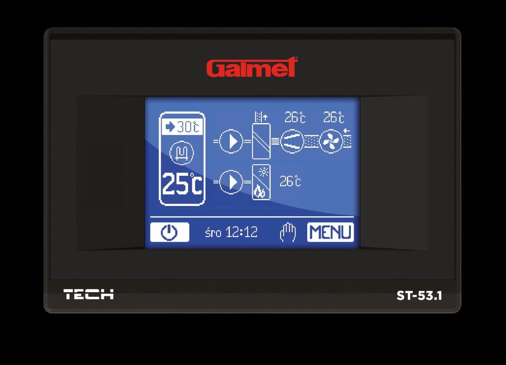
6 ST 53.1 User s manual IV. Operating the Controller IV.a) Principle of Operation The heat pump contains one heat generator as well as an optional electric heater by means of which heat is collected in a reservoir and heated to the pre-set temperature. The pump has a coil prepared for the connection of an external heat source, e.g. a CH boiler. The heat pump collects heat from the surrounding air and uses it to heat the water in the reservoir. The air and water heat pump delivers energy stored in the air and transfers it to a higher energy level. The temperature of energy collected in natural resources is too low for it to be directly used for heating. The ST-53.1 controller is adapted for the operation of a solar collector. The operation parameters regarding the solar collector are available in the controller's service menu. IV.b) Control Description of the control panel: Stand-by mode 2. Current tank temperature 3. Electrical heater 4. Pre-set tank temperature 5. Icon informing about active antifreeze function 6. Icon informing about switched on circulation pump 7. Pump 8. Exchanger 9. Compressor 10. Fan 11. Current evaporator temperature 12. Additional heat source icon visible only when an additional heat source is switched on. The graphic symbol changes when a solar collector is connected and activated. 13. Current temperature of additional heat source 14. Entering the controller's menu.
7 15. Icon informing about active operation mode or failure (symbol "!"), 16. Day of the week and hour 17. Pump of additional heat source 18. Icon informing about switched on weekly control: Tech - - Weekly control switched on, heat pump active (within the time range indicated by the weekly program). - - Weekly control switched on, heat pump not active (beyond the range indicated by the weekly program). The large touchscreen and clearly designed graphics of the ST-53.1 programmer enable the user to conveniently and almost intuitively operate a number of devices the heat pump is equipped with. The main screen graphically shows the operation of the devices of the heat pump's equipment, and as a result of this the user may directly control and supervise all basic system parameters. A moving animation of the device is a sign of its active operation. During the main screen view, by clicking on the reservoir, the user may quickly change the pre-set temperature of the tank. In a similar manner, the user may change the time and proceed to the menu. V. Controller Operation Modes The controller may operate in various operation modes. Information about the current operation mode is visible on the display (icon in the bottom part of the screen see description of the control panel in the previous chapter, number 15). V.a) Mode ECO PLUS Mode activity icon: This mode is activated automatically after the tank exceeds the ECO / ECO PLUS temperature threshold (setting in the servicing menu). The unit is then switched off, and the tank is additionally heated by the heater as well as the additional heat source (if it is switched on). V.b) Mode ECO Mode activity icon: This mode is activated automatically if the tank's temperature is lower than the value of the ECO / ECO PLUS threshold (setting in the servicing menu). Only the unit operates then, the heater does not operate. V.c) Manual Operation Mode activity icon: This mode is activated by the user in the servicing menu. After the user activates this mode and returns to the main screen, a click on the icon of a given device will activate it. The device remains switched on until the icon is touched again
8 ST 53.1 User s manual V.d) Compressor Failure Mode activity icon: This mode is activated automatically after the emergency temperature on the control sensor is exceeded. The unit is switched off. After the defect which caused the dangerous increase in temperature is repaired, the user should cancel the control temperature alarm in the servicing menu. NOTE In the case of compressor failure, the user should contact the person installing the device. V.e) Anti-Legionella Mode Mode activity icon: This mode is activated by the user in the controller's main menu. This is a mode in which the tank is thermally disinfected which process consists in increasing the tank's temperature to the value of disinfection temperature (see description in the following chapter). V.f) Mode STOP Mode activity icon: This mode is activated automatically in the case of the tank sensor's failure. In such a situation, the damaged sensor should be replaced or repaired and then the controller should be reset. V.g) Mode PARTY Mode activity icon: This mode is activated by the user in the controller's main menu. All possible sources of heat are activated in this mode so that the tank reaches the pre-set temperature as fast as possible. V.h) System Failure Mode activity icon: This mode is activated automatically in the case of the pressure switch sensor's failure. The unit is switched off. After the defect which caused damage to the pressure switch's sensor is repaired, the user should cancel the control temperature alarm in the servicing menu NOTE In the case of system failure, the user should contact the person installing the device
9 VI. Main Menu Tech After pressing the menu icon, the user proceeds to the review of cards with particular functions. The controller has five cards, each of which has no more than three functions. In order to proceed to adjusting the selected parameter, the user should touch the icon symbolizing this function. Touching the icon again moves the user to the screen enabling them to change the settings. The introduced changes are approved after the user touches any space on the screen, or the approval icon:. ICON ICON Party Mode LEGIONELLA Mode (on/off) Adjusting Current Time Parameter Card 4/5 Information on Maintenance and Software Version Access Protection (on/off) Protection Delay Setting days of the Week Tank Pre-Set Temperature Parameter Card 5/5 Language Selection Service Settings Tank Anti-Freeze Weekly Control (on/off) Adjusting the Weekly Control Circulation Pump V.a) Party Mode After switching the Party Mode on, the pump's heat tank reaches the pre-set temperature in the fastest possible time. All available heat sources operate simultaneously in this mode. V.b) LEGIONELLA Mode (Thermal Disinfection) Thermal Disinfection involves increasing the temperature to a necessary disinfection temperature of at least 60 C in the entire DHW circulation. New regulations impose the obligation to adjust the tank to periodical thermal disinfection conducted at a water temperature no lower than 60 C (recommended temperature 70 C). The ducts, fittings and technological system of hot water preparation need to comply with this condition. The boiler's disinfection is aimed to eliminate the Legionella Pneumophila bacteria which cause a reduction of the body's cell immunity. The bacteria often multiply in stagnant hot water tanks (optimum - 9 -
 and maintains this temperature for 30 minutes (factory setting) and then comes back into regular operation mode.")
10 ST 53.1 User s manual temperature 35 C), which frequently happens, e.g. in boilers. After activating the Legionella Mode, the boiler heats up to 70 C (factory setting) and maintains this temperature for 30 minutes (factory setting) and then comes back into regular operation mode. From the moment the disinfection is switched on, the temperature of 70 C needs to be reached in no longer than 90 minutes (factory setting). Otherwise, this function switches off automatically. Any changes of settings for this function are only possible in the servicing mode. V.c) Adjusting Current Time By setting the timer, the user defines the current time. Setting the time is necessary for the proper functioning of the Weekly control. V.d) Setting Days of the Week By using this function, the user sets the current day of the week. Setting the day of the week is necessary for the proper functioning of the Weekly control. V.e) Tank Pre-Set Temperature This function is used to set the pre-set tank temperature; this temperature may also be changed directly from the controller's Main Screen after clicking on the reservoir. V.f) Tank Anti-Freeze This function is used to specify anti-freeze actions used to protect the system against freezing. After the temperature drops below the specified temperature threshold (factory threshold is 5 C), the heat pump or the heater are activated permanently; they are switched off when the temperature in the circulation reaches the value of the temperature threshold plus 3 C (in the case of the factory setting, this will be 8 C). The user may select which device the anti-freeze function is to be applied to (heater or heat pump) and may also set the temperature threshold. V.g) Weekly Control This option is used to switch on / off the weekly control activity. Weekly control will operate properly after setting of the current time and day of the week. V.h) Adjusting the Weekly Control This function is used to program the heat pump's activity in a daily operation cycle for particular days of the week with accuracy to one hour. 1. After pressing the icon for adjusting the weekly control, a screen appears where the user may select the day of the week, the settings of which the user wishes to adjust: The user may change the day of the week using arrows or a slide. After selecting the day of the week the settings of which the user wishes to change, the user should click its name A screen for changing settings appears on the controller's display:
. Using the icon the user proceeds to the next settings screen with subsequent hours.")

11 Tech The user selects hours in which the heat pump is to be active (the hours: "06" and "07" are marked on the screenshot above this means that the heat pump is to be active between 06:00 and 07:59). Using the icon the user proceeds to the next settings screen with subsequent hours. After selecting the requested settings for the entire day, the user clicks the icon accepting the settings and, at the same time, proceeding to the screen for copying settings for other days. 3. The user may copy daily settings for: - business days after selecting this option, the daily settings are copied for days from Monday to Friday. - for Saturday Sunday after selecting this option, the daily settings are copied for weekends

 Circulation Pump It is possible to connect a circulation pump - with this function of the menu, the user may define particular operation parameters of this pump - operation time, pause time as")
12 ST 53.1 User s manual - for the entire week after selecting this option, the daily settings are copied for all remaining days of the week. - cancel the copying for other days of the week NOTE In order for the weekly control to be active, after selecting the settings of particular time intervals for the heat pump's activity the user should switch on the weekly control (Menu>> Weekly control>> Switch on). V.i) Circulation Pump It is possible to connect a circulation pump - with this function of the menu, the user may define particular operation parameters of this pump - operation time, pause time as well as hours and days of the week when the pump may be active. V.j) Information on Maintenance and Version After selecting this function, the display shows the logo of the heat pump's manufacturer, the software version as well as the telephone number for the device's servicing (the servicing telephone number may be changed in the servicing settings). V.k) Access Protection In order to protect the device against unwanted changes in settings, e.g. made by children, a lock has been introduced (access code) which is activated after a pre-set idle time. This function enables the user to activate this protection (switch on/ off) and enter the access code (by means of which it will be possible to activate the locked controller. V.l) Protection Delay In this setting the user declares the idle time after which the controller is locked (in seconds). In order
13 Tech to start programming the locked device, the user should press the padlock symbol on the display and enter the set access code. V.m) Language Selection This function enables the user to define the controller's language version. VII. Servicing Settings In order to start the controller's servicing menu, the user should enter a four-digit access code. The factory setting for this code is: If necessary, this code may be changed in the servicing menu. The servicing menu is operated like the main menu - after entering the servicing menu, the user proceeds to the review of cards with particular functions. The servicing menu has six cards, each of which has no more than three functions. When certain functions are switched on in the servicing menu, additional options appear - the number of cards may change. ICON ICON Parameter Card 1/7 Manual operation (on/off) Minimum Operation Temperature Heater Operation Below Minimum Temperature Parameter Card 5/7 LEGIONELLA Function Duration LEGIONELLA Function Maximum Time LEGIONELLA Function Reminder Parameter Card 2/7 Additional Heat Source (on/off) Displaying Additional Temperatures Unfreezing the Evaporator Parameter Card 6/7 Adjusting Servicing Telephone Number Delete Control Temperature Alarm Adjusting Access Code Parameter Card 3/7 Tank Pre-Set Temperature Hysteresis Threshold Temperature ECO- ECO PLUS System Protection Parameter Card 7/7 Factory Settings Parameter Card 4/7 Emergency Temperature Comressor Delay Legionella Function Temperature VI.a) Manual Operation After selecting this function, the screen view switches to the system view where the user clicks on the selected device on the display and switches it on / off in order to check the correctness of its operation
14 ST 53.1 User s manual VI.b) Minimum Working Temperature This function is used to define the minimum temperature (threshold) for the heat pump to switch on. VI.c) Heater Operation Below Minimum Temperature Using this function, the user should select whether the heater will operate (Switch on) below the minimum operation temperature, additionally heating the tank, or whether it should be switched off (Switch Off). V.d) Additional Heat Source This function is used to switch on / off the activity of the additional heat source. After pressing the icon of the additional heat source, the user changes the setting using the arrows: Switch Off After selecting this option, the controller will not operate the additional heat source. Solar Collector After selecting this option, the controller will operate the system equipped with a solar collector. Additional parameters, which will enable the user to configure the collector operation, will appear in the servicing menu. The icon of the solar collector will appear on the main screen. Additional Source After selecting this option, the controller will operate the system equipped with an additional heat source - e.g. a CH boiler. Additional parameters, which will enable the user to configure the operation of the additional source, will appear in the servicing menu. An icon for the additional source will appear on the main screen. Solar Collector Collector Switch on Delta Collector Switch Off Delta Collector Overheating Delta Additional Source Additional Source Switch on Temperature Additional Source Switch On Hysteresis Operation of Heat Source by Weekly Control Collector Overheating Temperature Maximum Collector Temperature Collector Anti-Freeze Minimum Collector Temperature Heat Pump Switch On Delay Circulation Sampling Tank Overheating Temperature Cooling Tank to Pre-Set Operation of Additional Source by Weekly Control Parameters of Solar Collector Collector Switch On Delta This function defines the difference between the temperature of the collector and the tank, at which point the pump begins to operate (it is the threshold value of pump when switched on). Collector Switch Off Delta This function defines the difference between the temperature of the collector and the tank, at which point the pump switches off (so as not to cool the tank)
15 Tech Collector Overheating Delta This parameter applies to the emergency pump switch on in the case of an excessive growth in temperature of the collector during standby mode. When the temperature rises to the value of the collector overheating temperature reduced by the value of overheating delta, the pump switches on. Collector Overheating Temperature It is the alarm collector temperature. If the collector temperature reaches the value of the collector overheating temperature reduced by the value of overheating delta, the pump is forced to switch on to cool down the solar panels. Hot water will be discharged regardless of the pre-set tank temperature. The pump will operate until its temperature drops below the alarm temperature by the value of overheating delta or until the tank reaches the maximum acceptable temperature. Maximum Collector Temperature This setting enables the user to set the value of the collector's maximum alarm temperature at which the pump may be damaged. This temperature should be set according to technical data of the owned collector. Due to the phenomenon of glycol "gelatinization" at high temperatures and the risk of damaging the solar pump, it is switched off after the maximum alarm temperature is reached (the regulator proceeds to its collector overheating mode). Collector Anti-Freeze Due to various freezing temperatures of fluids in the solar system, an anti-freeze temperature has been introduced. This parameter defines the minimum safe temperature at which the glycol liquid does not freeze (temperature measured by the collector). In the case of a significant drop in the collector's temperature (to the value of this parameter), the pump switches on and operates continuously until the collector heats up to a safe temperature. The settings range of this coefficient ranges within -50: +10 C. Minimum Collector Temperature This parameter defines the threshold value of the collector's temperature below which the pump will not switch on even if the solar pump switch on delta is reached. Heat Pump Switch On Delay When the collector's temperature drops below the tank's temperature, the heat pump is switched on with a delay as programmed in this parameter. Circulation Sampling This function enables the user to switch on (or off) circulation sampling aimed at updating the temperature reading consisting in a short activation of the collector's pump (when the regular conditions for the pump to switch on are not met). Circulation sampling may depend on the temperature (selected option Temperature Sampling) or on time (selected option Time Sampling). In the case of temperature sampling, the pump is switched on for a moment after each increase in the collector's temperature by 3⁰C. In the case of time sampling, the pump is switched on with a frequency defined by the user in the parameter Sampling Pause to a definite time in the parameter Sampling Time. Regardless of the type of sampling, it is not active if the collector's temperature drops below the sampling activation threshold value. Tank Overheating Temperature If the temperature on the solar panels increases excessively, the controller switches on the additional pump in order to cool the collector down. This pump will operate until the tank reaches the threshold value specified in this parameter. Cooling Tank to Pre-Set Cooling the tank to its pre-set temperature consists of switching on the additional pump when the tank's temperature exceeds the pre-set temperature and the solar panels are cooled down (e.g. at night). After this function is switched on, the controller switches on the additional pump in order to cool the tank down to the level of its pre-set temperature. Operation of Heat Source by Weekly Control This function defines whether the additional heat source pump will switch on simultaneously with the
16 ST 53.1 User s manual set weekly program (Switch On) or whether it will operate independently according to the set activation temperature (Switch Off). Parameters of Additional Source Activation Temperature of Additional Heat Source This option is used to set the Activation Temperature of the Additional Heat Source (it is the temperature measured on the additional source sensor). Below the pre-set temperature, the additional source pump does not operate, and above this temperature the pump is switched on until it reaches the pre-set tank temperature. Hysteresis of the Additional Heat Source Activation Temperature This option enables the user to define the temperature hysteresis of switching the additional heat source to the heat pump. It is the difference between the pre-set temperature (required on the heat pump - when the additional source pump switches off) and the temperature of activating the additional heat source pump again after the drop in temperature on the tank (for example: when the pre-set temperature has the value of 55 C and the hysteresis is 3 C. After reaching the pre-set temperature, namely 55 C, the additional source pump switches off. The additional source pump switches on again when the temperature drops to 52 C). Operation of Heat Source by Weekly Control This function defines whether the additional heat source pump will switch on simultaneously with the set weekly program (Switch On) or whether it will operate independently according to the set activation temperature (Switch Off). V.e) Displaying Additional Temperatures Activating this function will result in displaying readings from particular temperature sensors on the main screen. V.f) Evaporator defrosting This option is used for activation of the evaporator defrosting function. If the temperature of the evaporator sensor is lower than the temperature threshold set by the user, the compressor will be deactivated and the fan will work until the moment when the evaporator temperature reaches the threshold value increased by hysteresis value of the evaporator temperaturę. NOTE For the evaporator defrosting function to be possible to carry out, the external temperature must be higher than the Minimum working temperature. V.g) Tank Pre-Set Temperature Hysteresis This option enables the user to define the tank temperature hysteresis. It is the difference between the pre-set temperature (required on the boiler when the heat pump switches off) and the temperature when the heat pump returns to operation. V.h) Threshold Temperature ECO ECO PLUS The threshold ECO ECO PLUS is the tank's temperature at which the unit is switched off and further additional heating of the tank begins to proceed with the use of a heater and/or an additional heat source. V.i) System Protection The system protection's operation depends on the pressure switch, namely the pressure difference sensor. If this function is activated, the signal from the pressure switch transmitter with excessive pressure will switch off the pump and activate the alarm. V.j) Emergency Temperature Emergency temperature is a parameter protecting the compressor and the unit against overheating. If the temperature of the compressor on the control sensor increases in a hazardous manner (to the
17 Tech emergency temperature), the unit will be switched off permanently. In this case, the device may be started again only by the heat pump's manufacturer servicing crew. V.k) Compressor Delay After the heat pump is switched on, the fan and the pump are activated first and then, after several seconds, the compressor is activated. This setting regulates the compressor switch on delay time after the fan and the pump. When the pump reaches the ECO ECO PLUS threshold, first the compressor is switched off and then the fan and the pump, after the set delay. V.l) LEGIONELLA Function Temperature It is the pre-set temperature during the LEGIONELLA Function (thermal disinfection) duration. V.m) LEGIONELLA Function Duration This function enables the user to define the duration of disinfection (in minutes) in which the pre-set disinfection temperature will be kept at a permanent set level (LEGIONELLA Function Temperature). V.n) LEGIONELLA Function Maximum Duration It is the maximum total duration of disinfection (LEGIONELLA Function) from its activation (regardless of the temperature during the activation). When the tank does not reach the Pre-Set Temperature of Disinfection or does not keep the pre-set temperature during the LEGIONELLA Function Duration, then the controller will return to the basic operation mode after the Maximum Time. V.o) LEGIONELLA Function Reminder This function defines the number of days after which the controller's display will show a message with a reminder of the tank's thermal disinfection. Such reminder may be defined for no more than 90 days (factory setting - 10). If the value 0 is selected, the reminder will be disabled. V.p) Adjusting Servicing Telephone Number This setting enables the user to adjust the servicing telephone number displayed in the user's menu: Information on Maintenance and Version. V.r) Delete Control Temperature Alarm This parameter is protected with an additional code and is closely related to the function Emergency temperature. The protecting lock may be deleted only by the heat pump manufacturer's servicing crew. V.s) Adjusting Access Code This function enables the user to change the access code to the servicing menu. V.t) Factory Settings The controller is pre-configured for operation. However, the user should adjust it to their own needs. It is possible to return to factory settings at any time. When the option Factory Settings is activated, all user adjustments of the heat pump (saved in the user's menu) are lost and replaced by the manufacturer's factory settings. From this moment, the user's heat pump parameters may be defined once again. VIII. Standby Mode After pressing the button Standby Mode on the controller's main screen, the system's executive devices will be disconnected. The anti-freeze function remains active - if the temperature drops below the specified threshold, the heat pump or the heater are activated. This button is used when it is necessary to immediately switch off all devices. IX. Protections In order to ensure the maximum safe and reliable operation, the regulator has several protections. In the case of alarm, a sound signal is activated and a relevant message is shown on the display. In order for the controller to return to operation, the user should press OK on the touchscreen. In alarm, manual operation is possible, but it should be completely ensured whether the user's activities
18 ST 53.1 User s manual do not result in damage. The controller has the following alarm protections: 1. Additional sensor alarm. 2. Control sensor alarm (compressor). 3. Tank sensor alarm. 4. External sensor alarm. NOTE: higher amperage fuse should not be used. Higher amperage fuse should not be used as it may damage the controller. X. Maintenance Before and during the heating season the ST-53.1 controller should be checked for the condition of its cables. You should also check if the controller is properly mounted and clean it if dusty or dirty. Technical data Temperature Adjustment Range 30 o C : 65 o C Power Supply Voltage 230V/50Hz +/- 10% Power Consumption max. 7W Temperature Resistance of Sensors -25 o C : 95 o C Ambient Temperature 5 o C : 50 o C Compressor Output Load 1,1A Fan Output Load 0,6A Pump Output Load 0,5A Heater Output Load 2A Fuse Insert 6,3A
19 Tech Declaration of conformity No 153/2015 The company TECH, based in Wieprz 1047A, Wieprz, declares with complete liability that our temperature regulator ST V, 50Hz meets the requirements of the Regulation of the Minister of Economy, Labor and Social Policy (Journal of Laws No 155, item 1,089) dated August 21, 2007, implementing the provisions of the Low Voltage Directive (LVD) 2006/95/EC, the Act dated April 13, 2007 on electromagnetic compatibility (Journal of Laws ) implementing the provisions of Directive (EMC) 2004/108/EC, as well as the Regulation of the Minister of Economy dated May 8, 2013 "on basic requirements concerning on the restriction of the use of certain hazardous substances in electrical and electronic equipment" implementing the provisions of Directive ROHS 2011/65/EU. Harmonized standards were used to assess the conformity PN-EN :2011, PN-EN :2012. The product was marked with CE :

20 ST 53.1 User s manual
Declaration of Conformity no. 56/2012
 tech -1- ST 280 Instructions manual Declaration of Conformity no. 56/2012 We, TECH Sp.j., with our registered company office at Wieprz 1047A, 34-122 Wieprz, Poland declare under our full responsibility
Declaration of Conformity No. 27/2008
 ST-44 USER S MANUAL ST-45 User's Manual Declaration of Conformity No. 27/2008 Hereby, we declare under sole responsibility that the ST-45 230V 50Hz thermoregulator manufactured by TECH, ul. St. Batorego
TECH. Declaration of conformity no 23/2007
 ST-81 USER'S MANUAL TECH Declaration of conformity no 23/2007 We, company Tech, ul. St. Batorego 14, 34-120 Andrychów declare with full responsibility that ST-81, 230 V, 50 Hz thermo regulator that we
Room panel. for ecomax800 R or T regulators. OPERATION AND MAINTENANCE MANUAL ISSUE: 1.3 APPLICABLE TO SOFTWARE: v , v , v08.21.
 Room panel ecoster 200 for ecomax800 R or T regulators OPERATION AND MAINTENANCE MANUAL ISSUE: 1.3 APPLICABLE TO SOFTWARE: v08.21.014, v08.21.015, v08.21.016 2010-08-31 TABLE OF CONTENTS 1. SAFETY...
BIO 30, BIO 50, BIO 95
 BIO 30, BIO 50, BIO 95 STEEL BOILER FOR HEATING WITH BURNER AND AUTOMATIC FUEL FEEDER BIO 30-50 kw POWER USER MANUAL, USER GUIDE, INSTALLATION, USE AND MAINTENANCE OF THE BOILER 1. Introduction Biokaitra
SOLARCOMP 951 CONTROLLER FOR SOLAR COLLECTORS
 SOLARCOMP 951 CONTROLLER FOR SOLAR COLLECTORS Installation and Operating Instructions for model u7.x, Rev. 1, April 2014 Pb Safety Instructions Before installation read these Operation and Installation
1 DOCUMENT REVISION CONTROL ELEMENTS... 9
 CONTENTS Contents 1 DOCUMENT REVISION... 8 2 SOFTWARE VERSION... 8 3 BASIC DESCRIPTION... 8 4 CONTROL ELEMENTS... 9 4.1 BASIC DISPLAYS...10 4.2 CONTROL KEYS...11 4.2.1 Rotary button (Press / Turn)...11
Climapro 2. User manual. wireless room thermostat without receiver. To be left with the user.
 Climapro 2 User manual To be left with the user wireless room thermostat without receiver www.glow-worm.co.uk table of contents READ CAREFULLY BEFORE USING 1 Introducing your Climapro 2... 3 1.1 Description...
SD2. Differential Controller. Operating and Installation Instructions F2 72.3
 SD2 Differential Controller Operating and Installation Instructions F2 72.3 i Please follow the safety information and read these Instructions carefully before putting the system into operation. Safety
EUROSTER 11Z CENTRAL HEATING / UTILITY HOT WATER PUMP CONTROLLER
 EUROSTER 11Z USER MANUAL 1 EUROSTER 11Z CENTRAL HEATING / UTILITY HOT WATER PUMP CONTROLLER MANUFACTURER: P.H.P.U. AS, Polanka 8a/3, 61-131 Poznań, POLAND 1 INTRODUCTION Carefully study this user manual
For the owner and the heating engineer. Operating and Installation Manual VRC 400. Programmable weather compensator with separat HW time control
 For the owner and the heating engineer Operating and Installation Manual VRC 400 Programmable weather compensator with separat HW time control GB Contents Contents Notes on the documentation..... 4 Symbols
R. Room temperature controller with solar control FR 120. Operating instructions for the user (2012/02)
") 6 720 612 481-00.1R Room temperature controller with solar control FR 120 Operating instructions for the user 2 Dear Customer, The controller is the cool head of your heating system. At the factory, we
6 720 612 481-00.1R Room temperature controller with solar control FR 120 Operating instructions for the user 2 Dear Customer, The controller is the cool head of your heating system. At the factory, we
1 DOCUMENT REVISION SOFTWARE VERSION BASIC DESCRIPTION BASIC OVERVIEW OF HYDRAULIC DIAGRAMS HYDRAULIC DIAGRAMS...
 User Manual Contents 1 DOCUMENT REVISION... 4 2 SOFTWARE VERSION... 4 3 BASIC DESCRIPTION... 4 4 BASIC OVERVIEW OF HYDRAULIC DIAGRAMS... 5 4.1 BOILER NOT CONTROLLED BY THE CONTROLLER:... 5 4.2 BOILER CONTROLLED
Controller PCSol 300 FOR SOLAR COLLECTORS. INSTALLATION AND OPERATION MANUAL 62.X.2 REVISION SOFTWARE
 Controller PCSol 300 FOR SOLAR COLLECTORS www.econet24.com PUMP PUMP CIRCULATION PUMP ROTATION CONTROL CIRCULATION PROGRAM HEATER SUPPORT HEATER PROGRAM SIMPLE IN USE INTELLIGENT ALARM CLOCK 10 DAYS CLOCK
OPERATION MANUAL. Indoor unit for hot water heat pump system and options EKHBH016AB EKHBX016AB
 OPERATION MANUAL Indoor unit for hot water heat pump system and options EKHBH016AB EKHBX016AB EKHBH016AB*** EKHBX016AB*** Indoor unit for hot water heat pump system and options CONTENTS Page Introduction...1
Modulating clock thermostat
 EN Digital timer thermosatat Modulating clock thermostat Installation and Service Manual 123189-AB Contents 1 Preface...4 1.1 General...4 2 Location of the installation...5 2.1 Position of the regulator...5
TPOne-B. Electronic Programmable Room Thermostat. Installation Guide. Danfoss Heating
 TPOne-B Electronic Programmable Room Thermostat Danfoss Heating Installation Guide TPOne is an intelligent programmable heating control made easy. TPOne includes features which are designed to save energy.
PROGRAMMABLE 7-DAY THERMOSTAT
 PROGRAMMABLE 7-DAY THERMOSTAT Installation and user instruction This instructions to be retained by the user 1 Thank you for choosing Riello s weekly programmer.. This central heating control device is
Type UCG/UDG. English...1 Français...7 Español Up button. OK button. Down button
 USER MANUAL Type UCG/UDG 57116D 06/12 (MBC) 1.10 2012 OJ Electronics A/S...1 Français...7 Español... 14 Type UCG/UDG Contents Introduction...1 First Time Settings...1 Ground Fault Circuit Interrupter (GFCI)...1
INSTRUCTION FOR THE USER THC V E OIL BLU
 INSTRUCTION FOR THE THC V E OIL BLU CONTENTS General safety information 4 Precautions 4 Control panel 5 Mode selection 8 User levels 10 Start-up 12 Temporary shutdown 15 Preparing for extended periods
HMC300. Control unit. Operating Instructions. EMS plus (2014/10) O
 O") HMC300 Control unit EMS plus 6 720 808 471-00.1O Operating Instructions 6 720 813 192 (2014/10) Contents Contents Key to symbols and safety instructions................3 1.1 Key to symbols...........................
HMC300 Control unit EMS plus 6 720 808 471-00.1O Operating Instructions 6 720 813 192 (2014/10) Contents Contents Key to symbols and safety instructions................3 1.1 Key to symbols...........................
Lago SD3. Differential Controller with Speed Control. Operating and Installation Instructions
 Lago SD3 Differential Controller with Speed Control Operating and Installation Instructions Please observe the safety instructions and read through this manual carefully before commissioning the equipment.
Operation Manual NOVA LIVE S
 Operation Manual NOVA LIVE S Models: NLS 1000, NLS 1500 and NLS 2000 IMPORTANT SAFEGUARDS Before use, please read and follow these instructions carefully, even if you feel you are familiar with the product.
Field settings table [6.8.2] =... ID66F2. Applicable units *BLQ05CAV3 *DLQ05CAV3 *BLQ07CAV3 *DLQ07CAV3. Notes (*1) *B* (*2) *D* 1/8
![Field settings table [6.8.2] =... ID66F2. Applicable units *BLQ05CAV3 *DLQ05CAV3 *BLQ07CAV3 *DLQ07CAV3. Notes (*1) *B* (*2) *D* 1/8](/thumbs/95/126074615.jpg "Field settings table [6.8.2] =... ID66F2. Applicable units *BLQ05CAV3 *DLQ05CAV3 *BLQ07CAV3 *DLQ07CAV3. Notes (*1) *B* (*2) *D* 1/8") /8 [6.8.2] =... ID66F2 Applicable units *BLQ5CAV3 *DLQ5CAV3 *BLQ7CAV3 *DLQ7CAV3 Notes (*) *B* (*2) *D* 2/8 User settings Preset values Room temperature 7.4.. Comfort (heating) R/W [3-7]~[3-6], step: A.3.2.4
/8 [6.8.2] =... ID66F2 Applicable units *BLQ5CAV3 *DLQ5CAV3 *BLQ7CAV3 *DLQ7CAV3 Notes (*) *B* (*2) *D* 2/8 User settings Preset values Room temperature 7.4.. Comfort (heating) R/W [3-7]~[3-6], step: A.3.2.4
GENUS HE GENUS HE 24 GENUS HE 30 GENUS HE 38. User Manual. Condensing wall hung system boiler
 User Manual GENUS HE Condensing wall hung system boiler G.C.N : 47-116-54 (24 kw) G.C.N : 47-116-55 (30 kw) G.C.N : 47-116-56 (38 kw) GENUS HE 24 GENUS HE 30 GENUS HE 38 The code of practice for the installation,
USER MANUAL S203. Controller for three circuits. - control for 2 heating circuits - 1 domestic hot water control. Saving energy, creating comfort
 USER MANUAL S203 Controller for three circuits - control for 2 heating circuits - 1 domestic hot water control Saving energy, creating comfort This user manual consists of two parts. Issues that are intended
Sensor Cloud User Manual
 Sensor Cloud User Manual Table of Contents DEVICES TAB 4 1. DEVICE LIST 4 2. EXPAND ALL 4 3. EXPAND 4 4. STATUS 4 5. DEVICE 4 6. NAME 5 7. MONITORING INTERVAL 5 8. LAST ACTIVITY 5 9. VIEW 5 10. DELETE
Clima Infrared Radiant & Convection Panel
 Clima Infrared Radiant & Convection Panel Model S2030/1 Operating and Instruction Manual Please retain these instructions in a safe place for future reference. Ed. 05112015 cjw 1 References: n 1 min. 50cm
Condensing Boiler RS100 Controller Training Program
 Condensing Boiler RS100 Controller Training Program Training Program #501102A 062311 www.rinnai.us 2009 Rinnai America Corporation Features and Benefits The RS100 connects directly to the boiler and acts
INTRODUCTION... VI I. IOS... 1
 Contents INTRODUCTION... VI PURPOSE... VI KEY FUNCTIONS OF THE SYSTEM... VI TERMS AND ABBREVIATIONS... VII SMART HEATER APPLICATION:... X ios:... x Android:... x Windows:... x PRIVACY POLICY... XI ADAX
INTRODUCTION... VI I. IOS... 1
 Contents INTRODUCTION... VI PURPOSE... VI KEY FUNCTIONS OF THE SYSTEM... VI TERMS AND ABBREVIATIONS... VII SMART HEATER APPLICATION:... X ios:... x Android:... x Windows:... x PRIVACY POLICY... XI ADAX
User instructions DHP-AT
 User instructions DHP-AT VUGFC202 If these instructions are not followed during installation and service, Danfoss A/S liability according to the applicable warranty is not binding. Danfoss A/S retains
GA01HC-02. Service manual. Room Panel. Programme version 01a. Operating with GH07EA regulator for controlling electrode boilers
 Room Panel GA01HC-02 Operating with GH07EA regulator for controlling electrode boilers Programme version 01a Service manual We request that users carefully study applicable Instructions before connecting
REMOTE CONTROL FOR CHILLER MYCHILLER
 REMOTE CONTROL FOR CHILLER MYCHILLER GENERAL FEATURES... 3 MAIN FUNCTIONS AND EQUIPMENT:... 3 LCD DISPLAY... 4 KEYBOARD... 5 BOARD CONFIGURATION... 7 LIST OF MAIN PARAMETERS... 7 CONFIGURATION OF MAIN
Installation and user manual
 Installation and user manual Please read carefully and retain for future reference Models EcoHeat: C3, C5, C6, C8, C9, C11, C12 Rev.1_09-07-15 Page 1 Table of Contents 1 IMPORTANT: WARNINGS 1.1 GENERAL
User manual CLIMATIC 200/400 - Controller. Providing indoor climate comfort
 User manual CLIMATIC 2/4 - Controller Providing indoor climate comfort MUL35E-56 9-26 INDEX CONTENTS PAGE INDEX 1 GENERAL DESCRIPTION 2 THE KEYPAD, Climatic 2 3 THE KEYPAD, Climatic 4 4 THE KEYPAD REMOTE
OPERATION MANUAL. Daikin Altherma indoor unit EKHVMRD50ABV1 EKHVMRD80ABV1 EKHVMYD50ABV1 EKHVMYD80ABV1
 OPERATION MANUAL EKHVMRD50ABV1 EKHVMRD80ABV1 EKHVMYD50ABV1 EKHVMYD80ABV1 EKHVMRD50+80ABV1 EKHVMYD50+80ABV1 CONTENTS Page 1. Definitions... 1 2. Introduction... 2 2.1. General information... 2 2.2. Scope
Instruction manual. Aluminium radiator with ceramic heart. Smart Electric Heaters
 Instruction manual Aluminium radiator with ceramic heart Smart Electric Heaters READ THIS CAREFULLY BEFORE USING THIS DEVICE FOR THE FIRST TIME. PAY ATTENTION: to avoid overheating, do not cover the appliance.
Grant Aerona³. Air to Water High Efficiency Heat Pump Range. User Instructions
 Grant Aerona³ Air to Water High Efficiency Heat Pump Range User Instructions UK DOC 0112 Rev 1.0 April 2017 Special Tex t Formats The following special text formats are used in this manual for the purposes
USER MANUAL. OPTIMA 312 ES960C circuit board
 USER MANUAL OPTIMA 312 ES960C circuit board TABLE OF CONTENTS 1. Installation of Optima Design... 3 1.1 Installation of the Control Panel... 3 1.2 Mounting... 3 2. Control Panel... 4 3. Installation...
1/8. Field settings table. Applicable indoor units. *GSQH10S18AA9W ThermaliaC12* Notes - *GSQH10S18AA9W / ThermaliaC12* 4P C
 1/8 Applicable indoor units *GSQH1S18AA9W ThermaliaC12* Notes - *GSQH1S18AA9W / ThermaliaC12* 4P359382-1C - 214.3 2/8 3/8 User settings Preset values Room temperature 7.4.1.1 Comfort (heating) R/W [3-7]~[3-6],
OPERATION MANUAL RK-2006LPP AUGER FITTED SOLID FUEL BOILER TEMPERATURE CONTROLLER. Version DC19
 OPERATION MANUAL RK-2006LPP AUGER FITTED SOLID FUEL BOILER TEMPERATURE CONTROLLER Version DC19 1. Application. Controller RK-2006LPP is designed for temperature control of solid fuel fired water boilers
Safety. DANGER Indicates potentially fatal situations. WARNING Indicates possible danger to life and limb.
 Edition 06.14 GB Operating and installation instructions Lago FB digital remote control Translation from the German 2014 Elster GmbH Safety Please read and keep in a safe place Please read through these
R. Boiler Energy Management System FW 200. Operating Instructions for the User (2010/05)
") 720 12 481-00.1R oiler Energy Management System FW 200 Operating Instructions for the User 2 US/CA Dear Customer, The controls are the brain of your heating system. We have set it at the factory so that
720 12 481-00.1R oiler Energy Management System FW 200 Operating Instructions for the User 2 US/CA Dear Customer, The controls are the brain of your heating system. We have set it at the factory so that
THESE INSTRUCTIONS SHOULD BE READ CAREFULLY AND RETAINED FOR FUTURE REFERENCE.
 TE-700I Installation and Operating Instructions Haverland TOWELS THESE INSTRUCTIONS SHOULD BE READ CAREFULLY AND RETAINED FOR FUTURE REFERENCE. GENERAL RECOMMENDATIONS: * Please read these installation
Easy-Stat. Wireless Programmable Room Thermostat Pt No
 Easy-Stat Wireless Programmable Room Thermostat Pt No 7.2000050 1 Installing the receiver The receiver must be installed into the boiler control panel, refer to the boiler installation manual for guidance.
Inverter Swimming Pool Heat Pump
 P Inverter Swimming Pool Heat Pump Content I. Application... 2 II. Features... 2 III. Technical Parameter... 3 IV. Dimension... 4 V. Installation instruction... 5 VI. Operation instruction... 9 VII. Testing...
User s guide. Multiple programming Electronic thermostat
 SYSTÈME QUALITÉ CERTIFIÉ - REGISTERED QUALITY SYSTEM User s guide STE402P+ Multiple programming Electronic thermostat Energy Verified For further information or to consult this guide online, please visit
Operation manual. Daikin Altherma Low temperature split EHBH04CBV EHBH08CBV EHBH11CBV EHBH16CBV
 EHBH04CBV EHBH08CBV EHBH11CBV EHBH16CBV EHVH04S18CBV EHVH08S18CBV EHVH08S26CBV EHVH11S26CBV EHVH16S26CBV English Table of contents Table of contents 1 About this document 2 2 About the system 2 2.1 Components
OPERATION MANUAL RK-2001W2 SOLID FUEL FIRED BOILER TEMPERATURE CONTROLLER. Version 9A15
 OPERATION MANUAL RK-2001W2 SOLID FUEL FIRED BOILER TEMPERATURE CONTROLLER Version 9A15 1. Application. RK-2001W2 controller is a controller designed for temperature control of solid fuel fired boilers.
USERS GUIDE. Esprit eco 24, 30. For installation guide see reverse of book
 USERS GUIDE Esprit eco 24, 30 For installation guide see reverse of book When replacing any part on this appliance, use only spare parts that you can be assured conform to the safety and performance specification
EUROSTER 11E CENTRAL HEATING/UTILITY HOT WATER SYSTEM PUMP CONTROLLER
 EUROSTER 11E USER MANUAL 1 EUROSTER 11E CENTRAL HEATING/UTILITY HOT WATER SYSTEM PUMP CONTROLLER MANUFACTURER: P.H.P.U. AS, Polanka 8a/3, 61-131 Poznań, POLAND 1 INTRODUCTION Carefully study this user
HEATING REGULATOR EPC11 End user manual.
 HEATING REGULATOR EPC11 End user manual www.enerpipe.de 2 2011 ENERPIPE GmbH All rights reserved. This manual has been issued by ENERPIPE GmbH for use. ENERPIPE GmbH reserves the right to revisions and
System Installation. multi-zone heating
 System Installation multi-zone heating Table of contents INTRODUCTION 1 Instructions guidance... 2 1.1 Product documentation...2 1.2 Associated documents...2 1.3 Explanation of symbols...2 1.4 Guarantee
Alarm System SECURE AS 302
 Alarm System SECURE AS 302 Operating Manual SECURE Light app now available! Table of Contents Before You Start.................................. 4 User Information....................................4
Panel Convector Heater User Instructions
 Panel Convector Heater User Instructions LEVPH750TPR, LEVPH1250TPR, LEVPH1500TPR, LEVPH2200TPR IMPORTANT SAFEGUARDS Before use, please read and follow these instructions carefully, even if you feel you
Spa Touch Control Panel with BP2100, BP6013 spa controllers. (Spa Owner s Manual insert)
") Spa Touch Control Panel with BP2100, BP6013 spa controllers. (Spa Owner s Manual insert) P.N. 7876C (export) February 12, 2015 For Spas equipped with BP2100, BP6013 controllers and Spa Touch panel. Spa
Spa Touch Control Panel with BP2100, BP6013 spa controllers. (Spa Owner s Manual insert) P.N. 7876C (export) February 12, 2015 For Spas equipped with BP2100, BP6013 controllers and Spa Touch panel. Spa
AVANT DGi. Thermal Electric Radiator. Operating and Installation Instructions. (Read these instructions carefully and retain for future reference)
") (v13. 20180906) MODE CONFIG. PROG. AVANT DGi Thermal Electric Radiator Operating and Installation Instructions (Read these instructions carefully and retain for future reference) Models: AVANT-DGi 350
(v13. 20180906) MODE CONFIG. PROG. AVANT DGi Thermal Electric Radiator Operating and Installation Instructions (Read these instructions carefully and retain for future reference) Models: AVANT-DGi 350
multimatic Operating instructions AT, BE (de), CH (de), DE VRC 700f/4
, CH (de), DE VRC 700f/4") Operating instructions multimatic VRC 700f/4 AT, BE (de), CH (de), DE Publisher/manufacturer Vaillant GmbH Berghauser Str. 40 D-42859 Remscheid Tel. +49 21 91 18 0 Fax +49 21 91 18 2810 info@vaillant.de
Operating instructions multimatic VRC 700f/4 AT, BE (de), CH (de), DE Publisher/manufacturer Vaillant GmbH Berghauser Str. 40 D-42859 Remscheid Tel. +49 21 91 18 0 Fax +49 21 91 18 2810 info@vaillant.de
Instructions for Use. To b e l e f t w i t h t h e u s e r. Clearly Solar System. including. Fluropro. Solar Differential Controller
 Instructions for Use To b e l e f t w i t h t h e u s e r Clearly Solar System including Fluropro Solar Differential Controller 1 www.glow-worm.co.uk WARNINGS SAFETY The fluropro must be installed by a
SOTTOSTAZIONI PER TELERISCALDAMENTO DISTRICT HEATING SUBSTATIONS
 SOTTOSTAZIONI PER TELERISCALDAMENTO DISTRICT HEATING SUBSTATIONS INDEX Ed. 20150422 GENERAL INFORMATION... 2 Before installing... 2 Materials and PED (97/23/CE) Standards... 3 SKID-TYPE DISTRICT HEATING
/04.14_00. De Longhi Appliances via Seitz, Treviso Italia
 De Longhi Appliances via Seitz, 47 31100 Treviso Italia www.delonghi.com 5711010841/04.14_00 TRDS4 0820E - TRDS4 1025E DRAGON 4 OIL FILLED RADIATOR DESCRIPTION A L M B C D I F G H E N O 2 INSTRUCTIONS
INSTALLATION AND MAINTENANCE MANUAL BLITZ FD_
 INSTALLATION AND MAINTENANCE MANUAL IST 03 F 017-01 BLITZ FD_ Aluminium electric radiators with heat transfer fluid GB Dear customer, Thank you for choosing our product. Read this manual carefully before
Installation and operating instructions. Temperature difference controller 6 inputs, 3 outputs, integrated data logger for SD card
 SOLARTHERMIE - SOLAR THERMAL - SOLAR TÉRMICO - SOLAIRE THERMIQUE - SOLARE TERMICO Installation and operating instructions Temperature difference controller 6 inputs, 3 outputs, integrated data logger for
KTX 1, KTX 2, KTX 3, KTX 4. User Manual Electric Heating KTX 1, KTX 2, KTX 3, KTX 4.
 KTX 1, KTX 2, KTX 3, KTX 4. User Manual Electric Heating KTX 1, KTX 2, KTX 3, KTX 4. en Our products have been designed and manufactured in such a way to ensure that all the quality, functionality and
Control solutions Biofloor
 TEF234 Electronic room thermostat with display 230V & 24V COMAP proposes a new control system for heating and cooling underfloor. Consisting of a 6 or 10- channels controller (MCF234), analogic (TAF234)
USER MANUAL ACQUAHOME 32 B BLU
 USER MANUAL ACQUAHOME 32 B BLU Dear Customer, Thank you for preferring a T heating unit, a modern, high-quality product that is able to guarantee your maximum well-being for a long period of time, with
VIGÖR HRV PLUS AND VIGÖR ERV
 User Guide VIGÖR HRV PLUS AND VIGÖR ERV VB0147 Model no. 44202 (with top ports) VB0149 Model no. 44212 (with top ports) VB0148 Model no. 44203 (with side ports) VB0150 Model no. 44213 (with side ports)
Roth Touchline. German quality since Quick and easy user manual 1/10
 Roth Touchline Quick and easy user manual German quality since 197 1/10 230 V Pump N N L L 230 V 230 V 2 V 2 V c/o in %H c/o out c/o in Trafo out /TB in N L eco 2V CH 1 CH 2 CH 3 CH 2V 2V 2V 2V 2V Touchline,
Dohse Aquaristik GmbH & Co. KG
 A trademake of Dohse Aquaristik Instructions for use HumidityControl eco Item nr. 10896 Dohse Aquaristik GmbH & Co. KG www.dohse-terraristik.com Table of content 1. Introduction... 3 1.1 Display 1.2 Safety
Electronic Dual Cylinder Thermostat Installation Instructions
 ESCTDEB Electronic Dual Cylinder Thermostat Installation Instructions Thank you for choosing ESi Controls. All our products are tested in the UK so we are confident this product will reach you in perfect
EUROSTER 11B UTILITY HOT WATER TANK PUMP CONTROLLER
 1 EUROSTER 11B UTILITY HOT WATER TANK PUMP CONTROLLER MANUFACTURER: P.H.P.U. AS, Polanka 8a/3, 61-131 Poznań, POLAND 1 INTRODUCTION Carefully study this user manual to learn how to correctly operate the
Mounting and Operating Instructions EB 5610 EN. TROVIS 5600 Automation System TROVIS 5610 Heating and District Heating Controller
 TROVIS 5600 Automation System TROVIS 5610 Heating and District Heating Controller Mounting and Operating Instructions Electronics from SAMSON EB 5610 EN Firmware version 1.40 Edition December 2014 Controller
Semi flush-mount room thermostats
 s 1 440 RDD310/EH RDE410/EH Semi flush-mount room thermostats for control of electric floor heating systems and for hydronic zone control systems RDD310/EH RDE410/EH Key features of both types of thermostats:
Air-cooled heat pump USER MANUAL HBI IHBIFY _01
 Air-cooled heat pump USER MANUAL HBI GB IHBIFY. 0-625230_0 Index HBI control panel... 6 Control panel display... 7 HBI functioning mode... 9 COOLING Mode:... 9 HEATING Mode:... 9 DOMESTIC HOT WATER PRODUCTION
PROGRAMMABLE 7-DAY RF THERMOSTAT
 PROGRAMMABLE 7-DAY RF THERMOSTAT Installation and user instruction This instructions to be retained by the user 1 Thank you for choosing Beretta s radio frequency (RF) Radiostat. This central heating control
USERS GUIDE 24, 30. For installation guide see reverse of book
 USERS GUIDE 24, 30 For installation guide see reverse of book When replacing any part on this appliance, use only spare parts that you can be assured conform to the safety and performance specification
Dehumidifier User Manual. (For the series of DP40~DP70)
") Dehumidifier User Manual (For the series of DP40~DP70) Content I. Please read immediately... 1 II. Application... 2 III. Features... 2 IV. Technical Parameters... 3 V. Overall Dimension... 4 VI. Installation
Dehumidifier User Manual (For the series of DP40~DP70) Content I. Please read immediately... 1 II. Application... 2 III. Features... 2 IV. Technical Parameters... 3 V. Overall Dimension... 4 VI. Installation
OPERATION MANUAL. Indoor unit for air to water heat pump and sanitary warm water tank for air to water heat pump system EKHBH007A EKHBX007A
 OPERATION MANUAL Indoor unit for air to water heat pump and sanitary warm water tank for air to water heat pump system EKHBH007A EKHBX007A EKHBH007A*** EKHBX007A*** Indoor unit for air to water heat pump
User manual AG-WT10. Indoor unit air/air heat pump UHB GB
 User manual Indoor unit air/air heat pump UHB GB 1516-1 331557 Table of Contents 1 Important information Installation data Safety information Serial number an excellent choice Safety instructions Recovery
INSTRUCTION MANUAL REMOTE CONTROL DEVICE EASYREMOTE
 INSTRUCTION MANUAL REMOTE CONTROL DEVICE EASYREMOTE Technical features Guide to LCD symbols Guide to keys Technical features Supply by communication bus Number of temperature levels 2 (DAY / NIGHT) Temperature
Monitoring Software for NPBC-V3M-1 User Manual
 Monitoring Software for NPBC-V3M-1 User Manual User Manual ver 1.5 page 1 of 14 Contents: 1. Introduction... 3 2. Requirements... 3 3. Installing the software... 4 4. Connecting the devices... 4 5. Updating
OWNER S MANUAL. High-Wall Fan Coil Unit CONTENTS
 OWNER S MANUAL High-Wall Fan Coil Unit Page GENERAL 2,3 OPERATING MODES 2 REMOTE CONTROL 2 OPERATION 3-9 REMOTE CONTROL OPERATION 3 INDOOR UNIT DISPLAY 5 EMERGENCY OPERATION 5 PRESSING THE ON/OFF BUTTON
E-COMBI EVO E-SYSTEM EVO
 E-COMBI EVO E-SYSTEM EVO User s manual CONDENSING WALL-HUNG GAS BOILER G.C.N.:47-116-68 (24 kw) G.C.N.:47-116-69 (30 kw) G.C.N.:47-116-70 (38 kw) G.C.N.:41-116-39 (24 kw) G.C.N.:41-116-40 (30 kw) Country
Sensor Control Panel
 USER S MANUAL PU SENS 01 Sensor Control Panel V55-6EN-03(SENS).indd 1 18.08.2015 10:37:16 2 PU SENS 01 CONTENTS Safety Requirements 2 Main Technical Data 3 Control Panel Mounting 3 Control Panel Operation
Weekly thermostat for boilers Galan - regulator for management of heating elements and circuit SolarSentinel-DBTW Users guide.
 Weekly thermostat for boilers Galan - regulator for management of heating elements and circuit SolarSentinel-DBTW Users guide. SHORT DESCRIPTION: 1. Device is applicable to: - Burners; - Electric boiler;
Operating instructions
 Operating instructions Room controller 6 720 618 477-00.1RS Logamatic EMS RC35 programming unit For users Read carefully before use. 6 720 642 272 (10/2009) GB Overview of controls Overview of controls
User manual. CTS 602 by Nilan VPL 15 VPL 15 TOP. Version: 9.02, Software-version: 2.21
 User manual CTS 602 by Nilan VPL 15 VPL 15 TOP Version: 9.02, 19-05-2014 Software-version: 2.21 Table of contents Table of contents... 2 Figure table... 2 Introduction... 3 Types of units... 4 Review of
SAT-3 Room Temperature Controller
 SAT-3 Room Temperature Controller USER S OPERATING INSTRUCTIONS Contents Introduction 5 Features Summary 5 Operation 7 On/Off 7 Room Temperature Adjustment 7 Operating Mode Selection 8 Fan Speed Selection
GeyserWise MAX. Instruction manual. All in one hot water management
 GeyserWise MAX All in one hot water management Before operating and installation, carefully read all instructions. Do not discard this manual. DISPLAY The display is the feedback mechanism to the user
VR 90 Remote control unit
 For heating engineer/owner Operating and Installation Manual VR 90 Remote control unit Bus-modular control system GB VR 90 For the operator Operating manual VR 90 Remote control unit Bus modular control
Spa Touch Control Panel with 2000, 2100 controllers. (Spa Owner s Manual insert)
") Spa Touch Control Panel with 2000, 2100 controllers (Spa Owner s Manual insert) P.N. 7876B February 11, 2015 For Spas equipped with BP2000, BP2100 controllers and Spa Touch panel. Spa Touch Control Panel
Spa Touch Control Panel with 2000, 2100 controllers (Spa Owner s Manual insert) P.N. 7876B February 11, 2015 For Spas equipped with BP2000, BP2100 controllers and Spa Touch panel. Spa Touch Control Panel
GH10PA USER MANUAL. Program version 01 MANUAL FOR CONTROLLER FOR CONTROLLING CENTRAL HEATING BOILERS FIRED WITH PELLETS AND OATS
 MANUAL FOR CONTROLLER GH10PA FOR CONTROLLING CENTRAL HEATING BOILERS FIRED WITH PELLETS AND OATS Program version 01 USER MANUAL We request that users carefully study applicable Instructions before connecting
Digital Thermostat Models: VS30W and VS30B
 it600 VS30W - VS30B Installer - User Manual 015_Layout 1 28.07.2014 10:28 Digital Thermostat Models: VS30W and VS30B INSTALLER / USER MANUAL it600 VS30W - VS30B Installer - User Manual 015_Layout 1 28.07.2014
Air to Water Heat Pump -Mono Control Unit. user manual. imagine the possibilities
 Control Unit RC120MHXGA RC140MHXGA RC160MHXGA RC090MHXEA RC120MHXEA RC140MHXEA RC160MHXEA Air to Water Heat Pump -Mono Control Unit user manual imagine the possibilities Thank you for purchasing this Samsung
KFP-CF Series Operation Manual
 KFP-CF Series Operation Manual P/N 501-415103-2-31 REV 03.10 ISS 13NOV13 Copyright Trademarks and patents Manufacturer Version Certification European Union directives Contact information 2013 UTC Fire
Vokèra OpenTherm 711 without external sensor connected
 Vokèra OpenTherm 711 without external sensor connected Setup guide to using the OpenTherm Control without an external weather compensation sensor fitted. If you are unsure if there is an external sensor
Ultracom cxi. Instructions for Use. High Efficiency Condensing System Boilers. To b e l e f t w i t h t h e u s e r.
 Ultracom cxi High Efficiency Condensing System Boilers Instructions for Use To b e l e f t w i t h t h e u s e r WARNING GAS LEAK OR FAULT Turn off the gas emergency control valve immediately. Eliminate
CLEVER CONTROL Version: V3
 CLEVER CONTROL Version: V3 INSTALLATION AND FUNCTIONING MANUAL USER AND BASIC VERSION Please, read these instructions carefully before attempting installation SECURITY ADVISE SIMBOLS Attention, Danger,
GEYSERWISE INSTRUCTION MANUAL
 GEYSERWISE INSTRUCTION MANUAL GEYSERWISE MAX DELTA T ALL IN ONE HOT WATER MANAGEMENT Before operating and installation, carefully read all instructions. Do not discard this manual. INDEX 1. Package Contents