OPERATING MANUAL. Model 34134Z. Refrigerant Unit Recover, Recycle, and Recharge
|
|
|
- Maximilian Gibbs
- 6 years ago
- Views:
Transcription


1 OPERATING MANUAL Model 34134Z Refrigerant Unit Recover, Recycle, and Recharge
2 Recover, Recycle, and Recharge Unit Model: 34134Z Refrigerant: R-134a Voltage: 115, 60 Hz LISTED 80S2 Recycling Equipment Design Certified by Underwriters Laboratories Inc. for Compliance with SAE-J2210 (1991) for HFC-134a SAFETY DEFINITIONS: Follow all WARNING, CAUTION, IMPORTANT, and NOTE messages in this manual. These messages are defined as follows: WARNING means you may risk serious personal injury or death; CAUTION means you may risk personal injury, property damage, or serious unit damage; IMPORTANT means you may risk unit damage; and NOTEs provide clarity and helpful tips. These safety messages cover situations ROBINAIR is aware of. ROBINAIR cannot know, evaluate, and advise you as to all possible hazards. You must make sure all conditions and procedures do not jeopardize your personal safety. COPYRIGHT: No part of this manual may be reproduced, stored in a retrieval system, or transmitted in any form or by any means (electronic, mechanical, photocopy, recorded, or otherwise) without the prior written permission of ROBINAIR. DISCLAIMER: All information, illustrations, and specifications contained in this manual are based on the latest information available at the time of publication. The right is reserved to make changes at any time without obligation to notify any person or organization of such revisions or changes. Further, ROBINAIR shall not be liable for errors contained herein or for incidental or consequential damages (including lost profits) in connection with the furnishing, performance, or use of this material. If necessary, obtain additional health and safety information from the appropriate government agencies and the vehicle, refrigerant, and lubricant manufacturers. WARNINGS ALLOW ONLY QUALIFIED PERSONNEL TO OPERATE THE UNIT. Before operating the unit, read and follow the instructions and warnings in this manual. The operator must be familiar with air conditioning and refrigeration systems, refrigerants, and the dangers of pressurized components. If the operator cannot read these instructions, operating instructions and safety precautions must be read and discussed in the operator s native language. Si el operador no puede leer las instrucciones, las instrucciones de operación y las precauciones de seguridad deberán leerse y comentarse en el idioma nativo del operador. Si l utilisateur ne peut lire les instructions, les instructions et les consignes de sécurité doivent lui être expliquées dans sa langue maternelle. PRESSURIZED TANK CONTAINS LIQUID REFRIGERANT. Do not recover or charge refrigerants into non-refillable containers; use only authorized refillable containers. ALL HOSES MAY CONTAIN LIQUID REFRIGERANT UNDER PRESSURE. Contact with refrigerant may cause personal injury. Wear protective equipment, including safety goggles. Disconnect hoses with extreme caution. DO NOT BREATHE REFRIGERANT AND LUBRICANT VAPOR OR MIST. Exposure may cause personal injury, especially to the eyes, nose, throat, and lungs. Use the unit in locations with mechanical ventilation that provides at least four air changes per hour. If accidental system discharge occurs, ventilate the work area before resuming service. AVOID USING AN EXTENSION CORD. An extension cord may overheat and cause fire. If you must use an extension cord, use the shortest possible cord with a minimum size of 14 AWG. TO REDUCE THE RISK OF FIRE, do not use the unit in the vicinity of spilled or open containers of gasoline or other flammable substances. DO NOT USE COMPRESSED AIR TO PRESSURE TEST OR LEAK TEST THE UNIT OR VEHICLE AIR CONDITIONING SYSTEM. Some mixtures of air and refrigerant are combustible at elevated pressures. These mixtures are potentially dangerous and may result in fire or explosion causing personal injury or property damage. USE THIS UNIT WITH ONLY R-134a REFRIGERANT. The unit is for recovering, recycling, and recharging only R-134a refrigerant! Do not attempt to adapt the unit for another refrigerant. Do not mix refrigerant types through a system or in the same container; mixing of refrigerants will cause severe damage to the unit and the vehicle air conditioning system. HIGH VOLTAGE ELECTRICITY INSIDE THE UNIT HAS A RISK OF ELECTRICAL SHOCK. Exposure may cause personal injury. Disconnect the power before opening the back door or servicing the unit.
3 Table of Contents Safety Precautions... inside front cover Introduction... 2 General Description...2 Glossary of Terms...2 Component Identification and Location...3 Unit Front View...3 Unit Side View...3 Unit Back View...4 Vacuum Pump...4 Control Panel...5 Initial Setup... 6 Unpacking the Accessory Kit...6 Registering the Unit...6 Adding Vacuum Pump Oil...7 Adding Refrigerant to the Internal Storage Vessel...9 Drain Oil...11 Changing the Temperature Scale...12 Operation...13 Operating Guidelines...13 Recovering the A/C System Refrigerant...15 Draining the A/C System Oil...17 Evacuating the A/C System...18 Replenishing the A/C System Oil...19 Purging Air from the Internal Storage Vessel...20 Recharging the A/C System Refrigerant...21 Maintenance...23 Adding Additional Refrigerant to the Internal Storage Vessel...23 Drain Oil...24 Changing the Vacuum Pump Oil...25 Resetting Oil Time...26 Replacing the Filter-drier...27 Resetting the Filter-drier Capacity...29 Checking for Leaks...30 Calibrating the Weight Scale...31 Cleaning the Unit...31 Replacement Parts...31 R-134a Temperature / Pressure Table...32 Limited Warranty... inside back cover Manufactured under one or more of the following US patents: US 4,938,031; 5,005,369; 5,248,125; 4,261,178; 4,768,347. Other US and foreign patents pending. Recover/Recycle/Recharge Unit 1
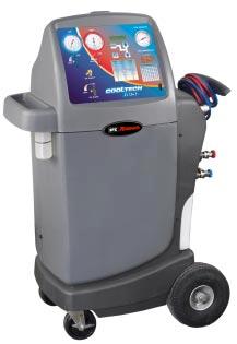
4 Introduction General Description INST0999 The 34134Z recovers, recycles, and recharges vehicle refrigerant in one hookup. It is compatible with existing service equipment and standard service procedures. Throughout this manual U.S. measurements are used with metric equivalents in parenthesis. Glossary of Terms A/C System The vehicle air conditioning system being serviced. Hose Storage Fittings When not in use, the R-134a service hose fittings can be connected to these fittings for storage purposes. Internal Storage Vessel (ISV) The refillable refrigerant storage vessel inside the unit. Panel Valves The high-side and low-side valves on the control panel, when described together. Service Couplers The couplers on the service hoses used to connect the hoses to the A/C system or to a source tank SPX Corporation
5 Introduction Component Identification and Location Unit Front View Tool Tray Control Panel Vacuum Pump Oil Inject Bottle Internal Storage Vessel Oil Drain Bottle Weight Scale INST1000 Unit Side View Hood Operating Manual Compartment Hose Storage Fittings Power Cord Service Hoses Source Tank Strap Source Tank Compartment INST1006 Recover/Recycle/Recharge Unit 3
6 Introduction Component Identification and Location contd. Unit Back View Circuit Breaker Filter-Drier INST1001 Vacuum Pump (Location shown on previous page) Oil Filler Cap and Tube (Included in accessory kit) Oil Fill Port Oil Sight Glass INST1003 Oil Drain Port SPX Corporation
7 Introduction Component Identification and Location contd. Control Panel High-Side Gauge Start/Stop Key Mode Key Display Screen Up Arrow Low-Side Gauge ISV Pressure Gauge High-Side Panel Valve (Valves shown closed) Low-Side Panel Valve Down Arrow ISV Temperature Display Temp/Pressure Chart Oil Inject Button Oil Drain Valve I O ON/OFF Power Switch Low-Side Valve controls the flow between the A/C system s low side and the unit. High-Side Valve controls the flow between the A/C system s high side and the unit. Low-Side Gauge shows the A/C system s low-side pressure. High-Side Gauge shows the A/C system s high-side pressure. Oil Inject Button injects new oil into A/C system. Display Screen displays operational information. Keypad contains the following keys for performing specific functions: MODE chooses function options. START/STOP starts, stops, or exits a function. UP/DOWN Arrows adjusts operating parameters. ISV Pressure Gauge shows the pressure inside the internal storage vessel. Oil Drain Valve drains the A/C system s oil into the oil drain bottle. ISV Temperature Display displays the temperature inside the internal storage vessel. Temp/Pressure Chart displays the pressure of a refrigerant at a given temperature. Recover/Recycle/Recharge Unit 5
8 Initial Setup WARNING This manual contains important procedures concerning the setup, operation, and maintenance of the unit. Read and follow all warnings at the beginning of this manual. Do not operate the unit until you have read and entirely understand the contents of this manual. If you do not understand any of the contents of this manual, notify your supervisor. If the operator cannot read these instructions, all instructions and safety precautions must be read and discussed in the operator s native language. Unpacking the Accessory Kit Unpack the accessory kit from the bag and remove the plastic packaging. The accessory kit consists of the following: l l l Vacuum pump oil, oil filler cap, and tube Plastic pouch containing a warranty card, applicable MSDS sheets, a service center listing, and an envelope of MACS information. Low side tank adapter Registering the Unit To comply with federal law governing A/C system service, you must complete and mail the MVAC Certification Form included in the accessory kit. You must also make sure your technicians are certified with the Mobile Air Conditioning Society (MACS). For more information, read the MACS information included in the accessory kit, or visit the MACS web site at To validate the warranty provided by SPX ROBINAIR, complete the warranty card included in the accessory kit, and mail it within ten days from the purchase date SPX Corporation
9 Initial Setup Adding Vacuum Pump Oil After registering the unit, use the following steps to add oil to the vacuum pump. IMPORTANT: For maximum unit performance, change the vacuum pump oil after every 10 hours of operation. (The unit will prompt a vacuum pump oil change after every 10 hours of operation. 1. Plug the unit s power cord into a correct voltage outlet. Oil Filler Cap and Tube (included in accessory kit) Oil Fill Port Oil Sight Glass CAUTION! Avoid using an extension cord. An extension cord may overheat and cause fire. If you must use an extension cord, use the shortest possible cord with a minimum size of 14 AWG. INST1003 Vacuum Pump 2. Remove the plastic plug from the oil fill port. 3. Attach the oil filler cap and tube to a vacuum pump oil bottle, and pour about 6 ounces (175 ml) of oil into the oil fill port. 4. Turn the unit s power switch on. 5. On the control panel, verify both panel valves are open, and verify the service couplers are disconnected from the vehicle. Screen will display: CLEAR Press Start/Stop key to start the vacuum pump. IMPORTANT! The vacuum pump is shipped without oil in the reservoir. To avoid pump damage, add oil before starting the pump. Recover/Recycle/Recharge Unit 7
10 Initial Setup Adding Vacuum Pump Oil contd. Note: The unit s weight default is in pounds. To change to kilograms: 1. Press the Up and Down arrow keys at the same time. UNITS LBS will be displayed. 2. Press the Up or Down arrow key to toggle to KG. 3. Press Mode key until display reads EXIT. NOTE: At this time, the unit is also automatically evacuating all air from the unit. 7. With the vacuum pump running, slowly add oil until the level rises to the center of the oil sight glass. 8. When the vacuum pump countdown reaches zero, the vacuum pump will stop and the unit display will change to the recover function. 9. Replace the plastic plug in the oil fill port. After adding oil to the vacuum pump, add refrigerant to the internal storage vessel. Refer to the instructions on the next page SPX Corporation
11 Adding Refrigerant to the Internal Storage Vessel Add refrigerant to the internal storage vessel (ISV) after adding oil to the vacuum pump. After the initial refrigerant fill, refill the ISV as necessary. (Refer to Adding Additional Refrigerant to the ISV in this manual.) WARNING Wear safety goggles when working with refrigerant. All hoses may contain liquid refrigerant under pressure. Disconnect hoses using extreme caution. Read and follow all warnings at the beginning of this manual before operating the unit. Initial Setup Service Hoses R-134a High-side Hose Storage Fitting R-134a Low-side Hose Storage Fitting Source Tank Compartment Source Tank Strap INST1006 Unit Components - Side View Recover/Recycle/Recharge Unit 9
12 Initial Setup Adding Refrigerant to the Internal Storage Vessel contd. 1. Connect the low-side tank adapter (from the accessory kit) to the liquid valve on the refrigerant source tank. NOTE: If using a refillable source tank, connect the tank adapter to the vapor valve. R-134a Tank Adapter 2. Connect the service coupler of the low-side hose (blue) to the refrigerant source tank. 3. Open the valve on the source tank, and place the tank upside down in the source tank compartment. Secure the source tank in place by wrapping the strap around the tank, and then fastening the strap. 4. The screen should display RECOVER XX.XXLBS. If it does not, scroll through the functions by pressing the Mode key until RECOVER XX.XXLBS is displayed. 5. Press the Arrow keys to adjust the recover weight to 15 lbs. (7 kg). 6. On the control panel, open the low-side valve; verify the high-side valve is closed. High-Side Gauge Start/Stop Key Mode Key Display Screen Up Arrow Low-Side Gauge ISV Pressure Gauge High-Side Panel Valve (Valves shown closed) Low-Side Panel Valve Down Arrow ISV Temperature Display Temp/Pressure Chart Oil Inject Button ON/OFF Power Switch Oil Drain Valve Control Panel I O SPX Corporation
13 Adding Refrigerant to the Internal Storage Vessel contd. Initial Setup 7. Press the Start/Stop key. The internal storage vessel begins filling, and the screen displays the amount of refrigerant being transferred to the internal storage vessel. 8. The unit will automatically stop when 15 lbs. (7 kg) has been transferred to the internal storage vessel. The display will flash between: RECOVER XX.XXKG and DRAIN OIL NOTE: Do not drain oil until the following steps are complete. Drain oil instructions are at the bottom of this page. 9. Unstrap the source tank, remove it from its compartment, then close the source tank valve. 10.Disconnect the hose from the tank. 11.Cap the source tank with its original tank cap. For storage, place the source tank upright in the source tank compartment. Secure the source tank in place by wrapping the strap around the tank, and then fastening the strap. 12.Do the following to clear the service hoses: a. Press Mode key to: RECOVER XX.XXLBS b. Press Start/Stop key to start hose clearing. c. Watch the low-side gauge. When the gauge pressure reaches 10 in. Hg (34 kpa) vacuum, press Start/Stop key to stop the clearing process. 13.Close the low-side panel valve. Drain Oil 1. On the control panel, open the oil-drain valve. Watch the oil drain into the oil-drain bottle. It may take 30 seconds or more for the oil to start draining. 2. When oil stops draining, close the oil-drain valve. Recover/Recycle/Recharge Unit 11
14 Initial Setup Changing the Temperature Scale (Fahrenheit or Celsius) The temperature scale is set to Fahrenheit at the factory. Use the following steps to toggle the temperature scale to Celsius. 1. Disconnect the unit s power cord from the outlet. WARNING High voltage electricity inside the unit has a risk of electrical shock. Disconnect the power before servicing the unit. 2. Remove the four screws that secure the top section of the unit s protective covering and remove the covering. 3. Locate the selector switch on the back of the tank temperature display. Selector Switch Control Panel Inside, Back View INST Change the position of the switch to change the temperature scale. 5. Replace the top section of the unit s protective covering, and replace the four screws that secure the covering SPX Corporation
15 Operation WARNING This manual contains important procedures concerning the setup, operation, and maintenance of the unit. Read and follow all warnings at the beginning of this manual. Do not operate the unit until you have read and entirely understand the contents of this manual. If you do not understand any of the contents of this manual, notify your supervisor. If the operator cannot these instructions, all instructions and safety precautions must be read and discussed in the operator s native language. Operating Guidelines For best results when operating the unit, use the following guidelines along with the operation instructions contained in this manual. The recovery compressor is not a vacuum pump. The compressor pulls the A/C system to a partial vacuum only. Use the Vacuum function for a minimum of 15 minutes to remove moisture from the A/C system. Refer to Evacuating the A/C System in the Operation section of this manual. The unit includes a 3 cfm high vacuum pump for fast, thorough evacuation. Change the vacuum pump oil after every 10 hours of vacuum pump use. The unit displays a CHANGE OIL message as a reminder. Refer to Changing the Vacuum Pump Oil in the Maintenance section of this manual. The unit is equipped with a circuit breaker button, located on the back of the unit. If the circuit breaker trips, the unit will not function correctly and will lose all power. If necessary, press the circuit breaker button to reset the unit. This unit should be operated between the ambient temperatures of F (11 49 C). At temperatures exceeding 104 F (40 C), wait 10 minutes between recovery jobs. Follow the SAE-J2211 recommended service procedure for the containment of R-134a refrigerant. During normal use, periodically inspect the unit for leaks. At a minimum, inspect the unit every three months. Refer to Checking for Leaks in the Maintenance section of this manual. Recover/Recycle/Recharge Unit 13
16 Operation Operating Guidelines contd. During operation, any of the following messages may appear on the display screen. If a message appears, immediately take the appropriate action. CHANGE FILTER This message appears after every 150 lbs. (68.0 kg) of refrigerant has been recovered, indicating that the filter-drier needs to be replaced. Refer to Replacing the Filter-Drier in the Maintenance section of this manual. NOTE: To avoid service delays, keep extra filter-driers on hand. CHANGE OIL This message appears after every 10 hours of vacuum pump use. Refer to Changing the Vacuum Pump Oil in the Maintenance section of this manual. DRAIN OIL This message appears after recovering refrigerant from an A/C system. For more information, refer to Draining the A/C System Oil in the Operation section of this manual. HIGH PRESSURE This message appears if the internal storage vessel s pressure rises to 435 psig (30 bar) or higher. Let the unit cool down for 30 minutes. Then press the Mode key and the Up arrow key to clear the message from the display screen. If the message does not clear, contact a manufacturer-authorized service technician. OVERLOAD This message appears if the weight of the internal storage vessel reaches 43 lbs. (19.5 kg), or if the unit s weight scale is damaged, disconnected, or out of calibration. Immediately remove refrigerant from the internal storage vessel. Then press the Mode key and the Up arrow key to clear the message from the display screen. If the message does not clear, contact a manufacturer-authorized service technician SPX Corporation
17 Operation Recovering the A/C System Refrigerant WARNING Wear safety goggles when working with refrigerant. All hoses may contain liquid refrigerant under pressure. Disconnect hoses using extreme caution. Read and follow all warnings at the beginning of this manual before operating the unit. Do not overfill the internal storage vessel. Overfilling may cause explosion and serious personal injury or death. If the message OVERLOAD appears in the display screen, the internal storage vessel is too full remove refrigerant. If the message HIGH PRESSURE appears in the display screen, let the unit cool down. If the message does not clear, call an authorized service technician. Do not recover or charge refrigerants into nonrefillable containers; use only authorized refillable refrigerant containers. Do not overfill refrigerant containers. Overfilling may cause explosion and serious personal injury or death. Use the unit only with R-134a refrigerant. The unit is for recovering, recycling, and recharging only R-134a refrigerant! Do not attempt to adapt the unit for another refrigerant. Do not mix refrigerant types through a system or in the same container; mixing of refrigerants will cause severe damage to the unit and the vehicle air conditioning system. Use the following steps to recover refrigerant from the vehicle s A/C system. 1. Plug the power cord into a correct voltage outlet. 2. Turn the unit on. 3. Connect the service hoses to the A/C system. IMPORTANT: Connect the red service hose to the A/C system s high side and the blue service hose to the low side. High-side Gauge Start/Stop Key Mode Key Display Screen Up Arrow Low-side Gauge ISV Pressure Gauge High-side Panel Valve (Valves shown closed) Low-side Panel Valve Down Arrow ISV Temperature Display Oil Inject Button Oil Drain Valve I O ON/OFF Power Switch Control Panel Recover/Recycle/Recharge Unit 15
18 Operation Recovering the A/C System Refrigerant contd. 4. Verify the oil drain valve is closed. 5. On the control panel, open both panel valves. 6. Press the Mode key until RECOVER X.XX LBS is displayed. (X.XX is the amount of refrigerant capacity remaining in the internal storage vessel [ISV].) Press the Start/Stop key to begin the recovery operation. Once recovery begins, the RECOVER X.XXLBS changes from the amount in the ISV to the amount being recovered. Note: Verify there is enough capacity in the ISV by comparing the amount of refrigerant in the A/C system to the amount on the display screen. The amount in the A/C system should not be greater than the amount initially displayed. If the amount is greater, charge some of the refrigerant from the ISV into another refillable refrigerant tank. IMPORTANT: The recovery compressor is not a vacuum pump. The compressor pulls the A/C system to a partial vacuum only. You must use the unit s vacuum (evacuate) cycle to remove moisture from the A/C system. 7. Watch the low-side gauge. When the pressure gauge reaches 10 in. Hg (34 kpa) vacuum, press the Start/Stop key. The display screen will indicate how much refrigerant has been recovered, and then toggle between: RECOVER XX.XXLBS DRAIN OIL and NOTE: Drain oil after the recovery is complete; refer to the next page for instructions regarding draining the oil. 8. Close both panel valves. 9. Wait 5 minutes, and then check the low-side gauge for a rise in pressure to above zero. If there is a rise in pressure, repeat steps 5 through 9 as needed until the pressure holds below zero for 2 minutes. NOTE: If the pressure does not drop to 10 in. Hg (34 kpa) vacuum or does not hold at 10 in. Hg (34 kpa) vacuum for at least 2 minutes, there was freezing in the A/C system during recovery or the A/C system requires repair. Repeat recovery or repair the A/C system as necessary. After recovering all refrigerant from the A/C system, drain the A/C system oil. Refer to the instructions on the next page. Note: The displayed recovered weight can vary, depending on ambient conditions, and should not be used as an indicator of scale accuracy SPX Corporation
19 Operation Draining the A/C System Oil After recovering the refrigerant from the A/C system, use the following steps to drain the A/C system oil into the unit s oil drain bottle. Oil Drain Valve Oil Drain Bottle INST0984 Oil Drain Bottle Location 1. Make sure the oil drain bottle is empty. Remove, empty, and replace the oil drain bottle if necessary. NOTE: Dispose of oil according to current local regulations. 2. On the control panel, open the Oil Drain valve. Watch the oil drain into the oil-drain bottle. It may take 30 seconds or more for the oil to start draining. 3. When the oil stops draining, close the Oil Drain valve. 4. Check the oil-drain bottle, and record the amount of oil removed. This is the amount of oil that must be added to the A/C system after evacuating the A/C system. Refer to step 2 in Replenishing the A/C System Oil in this manual. 5. Remove, empty, and replace the oil-drain bottle. After draining the oil, evacuate the A/C system. Refer to the instructions on the next page. Recover/Recycle/Recharge Unit 17
20 Operation Evacuating the A/C System After recovering all refrigerant from the A/C system, draining the oil from the system, and making repairs to the A/C system, use the following steps to evacuate (VACUUM) the A/C system. WARNING Wear safety goggles when working with refrigerant. All hoses may contain liquid refrigerant under pressure. Disconnect hoses using extreme caution. Read and follow all warnings at the beginning of this manual before operating the unit. 1. Verify the power cord is plugged into a correct voltage outlet, and the service hoses are correctly connected to the A/C system. Important: Connect the red service hose to the A/C system s high side, and the blue service hose to the low side. 2. On the control panel, open both panel valves. 3. Press the Mode key until the VACUUM screen displays. Press the Arrow keys to set the amount of time desired for the vacuum. Fifteen minutes is recommended, but the time may vary depending on environmental conditions. VACUUM 15:00 NOTE: The display screen shows the time as mm:ss; where mm represents minutes and ss represents seconds. Setting vacuum time to 0 (zero) will result in continuous vacuum pump operation. IMPORTANT: Check gauges to verify they are equal to or less than zero to prevent damage to the vacuum pump. 4. Press the Start/Stop key to begin the vacuum operation. Watch the vacuum time on the display. The display will count down the amount of time it will take to evacuate the A/C system. VACUUM When the evacuation is complete, the unit will automatically shut off, and INJECT OIL will display on the screen. 6. Close both panel valves on the control panel. 7. Note the pressure on the low-side gauge and then wait 5 minutes. 8. After waiting 5 minutes, check the low-side gauge for a rise in pressure. If the pressure remains stable, the evacuation is complete. If there is a rise in pressure, the A/C system may need further repairs or the evacuation may need to be repeated. Repeat the evacuation if necessary SPX Corporation
21 Operation Replenishing the A/C System Oil Before recharging the A/C system, replenish the A/C system oil. Add only the amount of oil that was removed during recovery. If no oil was removed, do not add any oil. NOTES: Refer to the A/C system manufacturer for correct oil replacement procedures and oil specifications. Replacing A/C system components may require adding more oil. Refer to component manufacturer for recommendations. 1. Refer to amount of oil that was removed during recovery (see step 4 in Draining the A/C System Oil ). 2. Fill oil inject bottle with new oil: Add 1 2 ounces (30 60 ml) more oil than was recovered. Add any additional oil required by an A/C component change. 3. Note the level of new oil in the bottle. 4. Place an o-ring around the oil inject bottle at the level the oil will be at after replenishing the system. Oil Inject Bottle O-ring Oil Drain Bottle For example, if the bottle s oil level is at 4 ounces, and you need 1/2 ounce of oil to replenish the A/C system, place the o-ring at the 3-1/2 ounce level. 5. Open the appropriate panel valve per the A/C system manufacturer s recommendations. 6. Push and hold the Oil Inject button until the system is replenished with the desired amount of oil. NOTE: To avoid getting air into the A/C system, do not remove all the oil from the oil inject bottle. To ensure the replenishment of oil into the A/C system, recharge the A/C system, leaving the panel valves in the same position as the A/C system manufacturer s recommendations. Refer to instructions on the next page to purge the air from the internal storage vessel prior to recharging. Recover/Recycle/Recharge Unit 19
22 Operation Purging Air from the Internal Storage Vessel Use the following steps to purge unwanted air from the internal storage vessel. Start/Stop Mode Display Up Key Key Screen Arrow ISV Pressure Gauge Down Arrow ISV Temperature Display Temp/Pressure Chart I O 1. On the control panel, note the internal storage vessel temperature in the ISV temperature display. NOTE: The ISV temperature display can show Fahrenheit or Celsius degrees. Refer to Changing the Temperature Scale in this manual. 2. Use this temperature to find the correct refrigerant pressure on the Temperature/Pressure Chart located in this manual or on the control panel. 3. Compare the pressure from the chart to the pressure shown on the unit s tank pressure gauge. If the pressure from the chart is lower than the gauge pressure, the internal storage vessel contains air. 4. To purge the air from the internal storage vessel, press Mode until PURGE AIR appears. 5. Press and hold the START/STOP button until the gauge pressure drops to the correct pressure from the chart. Then release the START/STOP button. 6. Wait 5 minutes to allow the temperature and pressure to stabilize. Check the temperature and pressure again. 7. If necessary, repeat the steps until the pressure is correct for the temperature. After purging the air, recharge the system SPX Corporation
23 Operation Recharging the A/C System Refrigerant WARNING Wear safety goggles when working with refrigerant. Hoses may contain liquid refrigerant under pressure; disconnect hoses using extreme caution. Read and follow all warnings at the beginning of this manual before operating the unit. After replenishing the A/C system oil as necessary and purging the A/C system, use the following steps to recharge the A/C system s refrigerant. NOTE: For maximum unit performance during recharging, make sure the refrigerant level in the source tank is at least 3 lbs. (1.4 kg) more than the amount required for recharging the vehicle being serviced. 1. Refer to the A/C system manufacturer s service manual to determine the required amount of refrigerant to recharge. 2. Verify the unit s power cord is plugged into a correct voltage outlet, and the service hoses are correctly connected to the A/C system. IMPORTANT: Connect the red service hose to the A/C system s high side and the blue service hose to the low side. 3. Verify the unit is turned on. IMPORTANT! This unit is designed for R-134a systems. Do not attempt to adapt the unit for another refrigerant system failure will result! 4. On the control panel, press the Mode key until the CHARGE XX.XX (XX.XX refers to the charge weight) screen displays. Use the Arrow keys to program how much to charge. Refer to the vehicle manufacturer s specifications on the amount to charge. 5. Open the appropriate panel valve(s) per the A/C system manufacturer s specifications. 6. Press the Start/Stop key to begin charging. The screen displays the amount of refrigerant being charged. 7. Watch the display screen. When the required amount appears, the screen will toggle between CHARGE COMPLETE and the amount that has been charged. CHARGE COMPLETE and CHARGE XX.XX 8. Close the panel valves. Recover/Recycle/Recharge Unit 21
24 Operation Recharging the A/C System Refrigerant contd. WARNING Before starting the vehicle s engine, verify the vehicle is in PARK or NEUTRAL, with the emergency brake ON. To prevent personal injury or death, never run a vehicle without adequate ventilation in the work area. 9. Start the vehicle s engine, turn the A/C system on for maximum cooling, and do the following: a. Watch the high-side and low-side gauges on the unit s control panel. Refer to the A/C system manufacturer s service manual to determine the correct pressures. b. Check the evaporator outlet temperature to be sure the A/C system is operating correctly. Refer to the A/C system manufacturer s service manual to determine the correct temperature. NOTE: If the pressures and temperature are not correct, the A/C system may still require repair. Complete the remaining steps, and then investigate and make any repairs as necessary. 10.Stop the vehicle s engine. 11.Open both panel valves until gauges equalize. 12.Close the coupler valves, and disconnect the service hoses from the A/C system. 13.Do the following to clear the service hoses: a. Press the Mode key and scroll to RECOVER XX.XX. Press the Start/Stop key. b. When the low-side gauge pressure reaches 10 in. Hg (34 kpa) vacuum, press the Start/Stop key. All refrigerant should be removed from the hoses. c. Close the panel valves SPX Corporation
25 Maintenance Adding Additional Refrigerant to the Internal Storage Vessel Periodically, the internal storage vessel (ISV) will require additional refrigerant. Use the following steps to add refrigerant to the ISV. 1. Connect the R-134a tank adapter to the liquid valve on the refrigerant source tank. 2. Connect the service coupler of the low-side hose (blue) to the adapter. NOTE: If using a refillable source tank, connect to the vapor valve. 3. Open the valve on the source tank, place the tank upside down in the source tank compartment, and secure the source tank strap around the tank. R-134a Tank Adapter 4. Press the Mode key until RECOVER XX.XXLBS (KG) is displayed. (XX.XX is the amount of refrigerant capacity remaining in the ISV.) 5. Press the Arrow keys to adjust to the desired recover weight. Note: Although the display shows the refrigerant capacity remaining in the ISV, the ISV should not be filled to this level. At least 9 lbs. (4 kg) of refrigerant capacity should be available in the ISV after filling to allow space for the next A/C recovery. Therefore, adjust the unit to fill the ISV to a level at least 9 lbs. (4 kg) less than what the display shows as the remaining refrigerant capacity. 6. On the control panel, open the low-side valve; verify the high-side valve is closed. 7. Press the Start/Stop key. The ISV begins filling, and the screen displays the amount of refrigerant being transferred to the ISV. 8. The unit will automatically stop when the desired amount has been transferred to the ISV. The display will flash between: RECOVER XX.XXLBS and DRAIN OIL NOTE: Drain oil after the internal storage vessel is filled. 9. Unstrap the source tank, remove it from its compartment, then close the source tank valve. 10.Disconnect the hose from the tank. 11.Cap the source tank with its original tank cap. For storage, place the source tank upright in the source tank compartment, and secure the source tank strap around the tank. Recover/Recycle/Recharge Unit 23
26 Operation Adding Additional Refrigerant to the Internal Vessel contd. 12.Do the following to clear the service hoses: a. Press Mode key to: RECOVER XX.XXLBS b. Press Start/Stop key to start hose clearing. c. Watch the low-side gauge. When the gauge pressure reaches 10 in. Hg (34 kpa) vacuum, press Start/Stop key to stop the clearing process. 13.Close the low-side panel valve. Drain Oil 1. On the control panel, open the oil-drain valve. Watch the oil drain into the oil-drain bottle. It may take 30 seconds or more for the oil to start draining. 2. When oil stops draining, close the oil-drain valve SPX Corporation
27 Maintenance Changing the Vacuum Pump Oil For maximum unit performance, change the vacuum pump oil after every 10 hours of operation. The unit keeps track of vacuum pump running time and will notify the user on the display screen when it is time to change oil. For optimum performance, use only Robinair Premium High Vacuum Oil. Use the following steps to change the vacuum pump oil. Oil Fill Port Sight Glass INST0983 Oil Drain Port Vacuum Pump 1. Remove the cap from the oil-drain port, and drain the oil into a suitable container (16 ounces [474 ml)] or larger) for disposal according to current federal, state, and local regulations. NOTE: Review current local, state, and federal statutes, cases, laws, and regulations to determine the correct disposal procedure for pump oil. It is the responsibility of the user to determine if a material is a hazardous waste at the time of disposal. Ensure you are in compliance with all applicable laws and regulations. 2. Replace the cap on the oil-drain port. 3. Remove oil fill cap. 4. Add 6 ounces of oil. 5. Verify panel gauges read less than Press Mode key until screen displays VACUUM XX.XX. Press Start/Stop key. 7. With the vacuum pump running, slowly add oil until the level rises to the center of the oil sight glass. 8. Press Start/Stop key. 9. Replace cap. After changing the vacuum pump oil, reset the vacuum pump oil timer. Recover/Recycle/Recharge Unit 25
28 Maintenance Resetting Oil Time Every time the vacuum pump oil is changed, the vacuum pump oil timer should be reset. Use the following steps to reset the oil timer. 1. Simultaneously press and hold the Up and Down arrow keys until the display shows UNITS LBS (KG). 2. Press the Mode key until the screen displays OIL XXX (XXX is minutes). 3. Simultaneously press and hold the Up and Down arrow keys until the screen displays OIL 600 (minutes). 4. Press Mode key until EXIT displays SPX Corporation
29 Maintenance Replacing the Filter-drier The filter-drier inside the unit removes acid, particulates, and moisture from refrigerant during the recovery function. To provide adequate contaminant and moisture removal, the filter-drier must be replaced after every 150 lbs. (68 kg) of refrigerant recovered. The following will appear in the display: CHANGE FILTER Use the following steps to replace the filter-drier. NOTE: For maximum unit performance, use only No SPX/ROBINAIR filter-drier. To avoid service delays, keep extra filter-driers on hand. Refer to the Replacement Parts section of this manual. 1. Plug the power cord into a correct voltage outlet, and turn the unit on. 2. Verify the service hoses are NOT connected to a vehicle. High-Side Gauge Start/Stop Key Mode Key Display Screen Up Arrow Low-Side Gauge ISV Pressure Gauge High-Side Panel Valve Valves shown closed Low-Side Panel Valve Down Arrow ISV Temperature Display Temp/Pressure Chart Oil Inject Button Oil Drain Valve I O ON/OFF Power Switch Control Panel 3. On the control panel, open both panel valves. 4. Press the Mode key until RECOVER XX.XX displays on the screen. 5. Press the Start/Stop key. 6. Watch the low-side gauge. When the gauge pressure reaches 10 in. Hg (34 kpa) vacuum, close both panel valves. 7. Turn the unit s power switch off. 8. Remove the unit s power cord from the outlet. Recover/Recycle/Recharge Unit 27
30 FLOW # Maintenance Replacing the Filter-drier contd. WARNING High voltage electricity inside the unit has a risk of electrical shock. Disconnect the power before opening the back door or servicing the unit. 9. Open the back door of the unit s protective covering. To unlock the door, turn the two screws 1/4 turn counterclockwise. Filter-Drier INST1001 Filter-drier Location (Back View of Unit) 10.Remove the strap, disconnect the fittings from the filter-drier, and remove the filter-drier. NOTE: Dispose of the filter-drier according to current federal, state, and local regulations. 11.Install the new filter-drier with the FLOW direction arrow pointing down, tighten the fittings, and secure with the strap. 12.Close and lock the back door of the unit s plastic covering. To lock the door, turn the two screws 1/4 turn clockwise. After replacing the filter-drier, reset the filter-drier capacity. Refer to the instructions on the next page SPX Corporation
31 Maintenance Resetting the Filter-drier Capacity The unit keeps track of the filter-drier s remaining capacity. As the unit filters refrigerant, the remaining capacity decreases from 150 lbs. (68 kg) to zero. When the capacity reaches zero, the unit will display: CHANGE FILTER Use the following steps to reset the filter-drier s capacity. 1. Plug the power cord into a correct voltage outlet, and turn the unit on. 2. Simultaneously press and hold the Up and Down arrow keys until UNITS LBS (KG) appears on the display. 3. Press the Mode key until FILTER XXX appears on the display. 4. Simultaneously press and hold the Up and Down arrow keys until FILTER 150 LBS (68 KG) appears on the display. 5. Press the Mode key until EXIT displays. 6. Press the Start/Stop key to exit the diagnostics function. The unit is now ready to begin counting down the capacity of the new filter-drier. Recover/Recycle/Recharge Unit 29
32 Maintenance Checking for Leaks Over time, fittings can loosen as the unit is used and moved. During normal use, inspect the unit for leaks at a minimum of every three months (or as specified by current federal, state, and local regulations). Use the following steps to check the unit for leaks. NOTE: The manufacturer does not reimburse for lost refrigerant. 1. Remove the power cord from the outlet. WARNING High voltage electricity inside the unit has a risk of electrical shock. Disconnect the power before opening the back door or servicing the unit. 2. Remove the four screws that secure the hood. 3. Remove the hood. 4. Open the back door of the unit s protective covering, and lift the door off the unit. To unlock the door, turn the two screws 1/4 turn counterclockwise. 5. Remove the five screws that secure the front section of the unit s protective covering, and remove the covering. 6. Use a leak detector to trace all lines, and check all connections for refrigerant leaks. Tighten any fittings or connections if a leak is indicated. WARNING DO NOT use compressed air to pressure test or leak test the unit. Some mixtures of air and refrigerant are combustible at elevated pressures. These mixtures are potentially dangerous and may result in fire or explosion. 7. Replace the unit s protective covering as follows: a. Replace the front section, and replace the five screws that secure the covering. b. Replace, close, and lock the back door. To lock the door, turn the two screws 1/4 turn clockwise. c. Replace the hood and the four screws that secure the hood SPX Corporation
33 Maintenance Calibrating the Weight Scale The unit s weight scale is calibrated at the factory and requires no further calibration. NOTE: If the message OVERLOAD appears on the display screen on the control panel, the weight of the internal storage vessel is too high, or the unit s weight scale is damaged, disconnected, or out of calibration. Call a qualified service technician. Cleaning the Unit On a regular basis, wipe off the unit with a clean cloth to remove grease, dust, or other dirt. Replacement Parts The following is a list of replacement parts and accessories for the unit. For ordering information, use the technical support telephone number listed on the back cover of this manual. Part No. Description Premium High Vacuum Pump Oil Case of 4 Gallons Premium High Vacuum Pump Oil Case of 12 Quarts Premium High Vacuum Pump Oil Case of 12 Pints Oil Drain Bottle 18191A 18190A Filter-Drier High-side Service Coupler Low-side Service Coupler Blue Service Hose Red Service Hose Recover/Recycle/Recharge Unit 31
34 R-134a Temperature / Pressure Table Conversion Table OZ. LBS lb. Temperature Pressure F C PSIG Temperature Pressure F C PSIG SPX Corporation
35 Robinair Limited Warranty Statement Rev. November 1, 2005 Limited Warranty This product is warranted to be free from defects in workmanship, materials, and components for a period of one year from date of purchase. All parts and labor required to repair defective products covered under the warranty will be at no charge. The following restrictions apply: 1. The limited warranty applies to the original purchaser only. 2. The warranty applies to the product in normal usage situations only, as described in the Operating Manual. The product must be serviced and maintained as specified. 3. If the product fails, it will be repaired or replaced at the option of the manufacturer. 4. Transportation charges for warranty service will be reimbursed by the factory upon verification of the warranty claim and submission of a freight bill for normal ground service. Approval from the manufacturer must be obtained prior to shipping to an authorized service center. 5. Warranty service claims are subject to authorized inspection for product defect(s). 6. The manufacturer shall not be responsible for any additional costs associated with a product failure including, but not limited to, loss of work time, loss of refrigerant, cross-contamination of refrigerant, and unauthorized shipping and/or labor charges. 7. All warranty service claims must be made within the specified warranty period. Proof-of-purchase date must be supplied to the manufacturer. 8. Use of recovery/recycling equipment with unauthorized refrigerants or sealants will void warranty. Authorized refrigerants are listed on the equipment or are available through the Technical Service Department. The manufacturer prohibits the use of the recovery/recycling equipment on air conditioning (A/ C) systems containing leak sealants, either of a seal-swelling or aerobic nature. This Limited Warranty does NOT apply if: The product, or product part, is broken by accident. The product is misused, tampered with, or modified. The product is used for recovering or recycling any substance other than the specified refrigerant type. This includes, but is not limited to, materials and chemicals used to seal leaks in A/C systems SPX Corporation Recover/Recycle/Recharge Unit
36 Visit our web site at % or Call our Toll-Free Technical Support Line at in the continental U.S. or Canada. In all other locations, contact your local distributor. To help us serve you, be prepared to provide the model number, serial number, and date of purchase of your unit. To validate your warranty, complete the warranty card attached to your unit, and return it within ten days from date of purchase. NATIONWIDE NETWORK OF AUTHORIZED SERVICE CENTERS If your unit needs repair or replacement parts, contact the service center in your area. For help in locating a service center, call the toll-free technical support line or visit our website. Due to ongoing product improvements, we reserve the right to change design, specifications, and materials without notice. The 34134Z units are designed to meet all applicable agency certifications, including Underwriter s Laboratories, Inc., SAE Standards, and CUL. Certain state and local jurisdictions dictate that using this equipment to sell refrigerant by weight may not be permitted. We recommend charging for any A/C service by the job performed. This weight scale provides a means of metering the amount of refrigerant needed for optimum A/C system performance as recommended by OEM manufacturers. SPX Corporation 655 Eisenhower Drive Owatonna, MN USA Technical Services: Fax: Customer Service: Fax: Web Site: com Rev. B (November 18, 2005) 2003 SPX Corporation
Owner s Manual. Model AC375C Refrigerant Recovery, Recycle, and Recharge Unit
 Owner s Manual Model AC375C Refrigerant Recovery, Recycle, and Recharge Unit Model AC375C Recover, Recycle, and Recharge Unit for R-12 or R-134a Refrigerant Voltage: 220 230; 50 60 Hz SAFETY DEFINITIONS:
Operating Manual. Model 34700Z / 17700Z Recovery, Recycling, Recharging Unit
 Operating Manual Model 34700Z / 17700Z Recovery, Recycling, Recharging Unit Model 34700Z / 17700Z Recovery, Recycling, & Recharging Unit SAFETY DEFINITIONS: Follow all WARNING, CAUTION, IMPORTANT, and
Operating Manual. Model K/ K Recovery/Recycling/Recharging Unit
 Operating Manual Model -K/-K Recovery/Recycling/Recharging Unit Model -K (for R- refrigerant) Model -K (for R-a refrigerant) Recover, Recycle, and Recharge Unit SAFETY DEFINITIONS: Follow all WARNING,
Model Operating Manual for. Recovery, Recycling, Recharging Unit P E R A T I N G A N U A L
 O P E R A T I N G 99 Washington Street Melrose, MA 02176 Phone 781-665-1400 Toll Free 1-800-571-8431 Visit us at www.testequipmentdepot.com M A N U A L Operating Manual for Model 34288 Recovery, Recycling,
Model K / K. Modelo K / K. Modèle K / K. Operating Manual
 Operating Manual Model 34800-2K / 34801-2K Recovery/Recycling/Recharging Unit for R-12 and R-134a Refrigerants... English Modelo 34800-2K / 34801-2K Unidad de recuperación/reciclaje/recarga para refrigerantes
P E R A T I N G A N U A L. Operating Manual for. Model Recovery, Recycling, Recharging Unit
 O P E R A T I N G M A N U A L Operating Manual for Model 34788 Recovery, Recycling, Recharging Unit Model 34788 Recovery, Recycling, & Recharging Unit SAFETY DEFINITIONS: Follow all WARNING, CAUTION, IMPORTANT,
Model Operating Manual for. Recovery, Recycling, Recharging Unit P E R A T I N G A N U A L
 O P E R A T I N G 99 Washington Street Melrose, MA 02176 Phone 781-665-1400 Toll Free 1-800-571-8431 Visit us at www.testequipmentdepot.com M A N U A L Operating Manual for Model 34788 Recovery, Recycling,
DiscovR R134a Refrigerant Identifier
 Model 16009 DiscovR R134a Refrigerant Identifier Operating Manual Table of Contents Safety Precautions... 1 Description... 4 Operating Instructions.... 5 Fault Codes.... 7 Troubleshooting... 7 Replacement
Operating Manual. Model Refrigerant Service Solution
 Operating Manual Model 342000 Refrigerant Service Solution Series: 342000 Refrigerant: R-134a Air Conditioning and Refrigerant Service Solution SAFETY DEFINITIONS: Follow all WARNING, CAUTION, IMPORTANT,
Operating Manual, Model K/348012K Recovery/Recycling/Recharging Unit For R-12 and R-134a Refrigerants...1
 Operating Manual, Model 348002K/348012K Recovery/Recycling/Recharging Unit For R-12 and R-134a Refrigerants...1 Refrigerant Recovery, Recycling and Recharging Station Series: 348002K/348012K Refrigerants:
Operating Manual for. Model Recovery, Recycling, Recharging Unit
 Operating Manual for Model 34988 Recovery, Recycling, Recharging Unit Model 34988 Recovery, Recycling, & Recharging Unit SAFETY DEFINITIONS: Follow all WARNING, CAUTION, IMPORTANT, and NOTE messages in
Operating Manual Manual de Operación Manuel d utilisation
 Operating Manual Manual de Operación Manuel d utilisation Model 17800B/17801B Recovery/Recycling/Recharging Unit for Multiple Refrigerants... 1 Modelo 17800B/17801B Unidad de recuperación/reciclado/recarga
Refrigerant Recovery Machine. Model No Operating Manual
 Refrigerant Recovery Machine Model No. 25700 Operating Manual Safety Precautions WARNING : TO PREVENT PERSONAL INJURY AND / OR EQUIPMENT DAMAGE, CAUTION - Risk of injury. This equipment should only be
Operation Manual... 1 Manuel d utilisation Manual de Operación.. 60
 Operation Manual... 1 Manuel d utilisation... 30 Manual de Operación.. 60 SERIES: ACR2000 KENT-MOORE: J-43600 Air Conditioning and Refrigerant Service Solution WARNING Refrigerant: R134a PRESSURIZED TANK
Original Instructions Instucciones originales Consignes originales. Model: AC R-1234yf A/C Recover, Recycle, Recharge Machine
 Original Instructions Instucciones originales Consignes originales Model: AC1234-6 R-1234yf A/C Recover, Recycle, Recharge Machine Description: Recover, recycle, and recharge machine for use with R-1234yf
Operating Manual. Series 12134B Recovery/Recycling/Recharging Unit for R-12 and R-134a
 Operating Manual Series 12134B Recovery/Recycling/Recharging Unit for R-12 and R-134a LISTED 80S2 Design Certified by Underwriters Laboratories Inc., to meet SAE J1770 for recycling R-12 and R-134a using
RecoverX-CAR Contaminated Automotive Refrigerant Recovery System Operation and Maintenance Manual
 RecoverX-CAR Contaminated Automotive Refrigerant Recovery System Operation and Maintenance Manual (English) Table of Contents Page General Safety Instructions...2 System Overview...3 RecoverX-CAR Operation
OPERATION & MAINTENANCE MANUAL RHS680
 OPERATION & MAINTENANCE MANUAL RHS680 Refrigerant Handling System 4075 East Market Street York, PA 17402 800-468-2321 tech@rtitech.com Manual P/N 035-80740-00 (Rev 1- May 22, 2001) TABLE OF CONTENTS Startup
Model AC Original Instructions. Recover, Recycle, Recharge Machine for R1234yf A/C Systems
 Original Instructions 99 Washington Street Melrose, MA 02176 Phone 781-665-1400 Toll Free 1-800-517-8431 Visit us at www.testequipmentdepot.com Model AC1234-6 Recover, Recycle, Recharge Machine for R1234yf
OPERATION & MAINTENANCE MANUAL AC860
 OPERATION & MAINTENANCE MANUAL AC860 Refrigerant Handling System Manual P/N 035-80913-00 TABLE OF CONTENTS Startup & Safe Operation... 1 Introduction to the AC860... 2 Control Panel... 3 Keypad Functions...
Operation and Maintenance Manual
 Warranty Information Ritchie Engineering guarantees YELLOW JACKET products to be free of defective material and workmanship which could affect the life of the product when used for the purpose for which
RecoverX Oil-Filled Hermetic Refrigerant Recovery System. Operation and Maintenance Manual
 RecoverX Oil-Filled Hermetic Refrigerant Recovery System Operation and Maintenance Manual Table of Contents Page General Safety Instructions 2-3 System Overview 3 Operating Guide 4 Restart Procedure 4
OWNER S MANUAL (English)
") TR600 Series Refrigerant Recovery Machines OWNER S MANUAL (English) Français, Español, Deutsch and latest updates: www.cpsproducts.com Series: TR600, TR610, TR600C, TR610C, TR600S, TR600K, TR600E TO BE
TR600 Series Refrigerant Recovery Machines OWNER S MANUAL (English) Français, Español, Deutsch and latest updates: www.cpsproducts.com Series: TR600, TR610, TR600C, TR610C, TR600S, TR600K, TR600E TO BE
347002K/177002K/34900
 Service Manual Models: 347002K/177002K 34900/347012K Manifold Block Style Recovery/Recycling/Recharging Unit For R-12 or R-134a Only TABLE OF CONTENTS: Theory of Operation and Safety Precautions... 2 Depressurizing
OPERATION & MAINTENANCE MANUAL TC670
 OPERATION & MAINTENANCE MANUAL TC670 Refrigerant Management Center (Convertible For Use With R12 or R134a) RTI TECHNOLOGIES, INC. 4075 East Market Street York, PA 17402 Manual P/N 035-80342-02 TC670 CONVERTIBLE
TRS21 IGNITION PROOF SERIES
 TRS21 IGNITION PROOF SERIES 2 Cylinder Commercial Recovery Machine OWNER S MANUAL (English) Français, Español, Deutsch and latest updates: www.cpsproducts.com Series: TRS21, TRS21C, TRS21S Evaluated for
TRS21 IGNITION PROOF SERIES
 TRS21 IGNITION PROOF SERIES 2 Cylinder Commercial Recovery Machine OWNER S MANUAL (English) Français, Español, Deutsch and latest updates: www.cpsproducts.com Series: TRS21A, TRS21E TO BE OPERATED BY QUALIFIED
Enspeco RMS. The Enspeco Refrigerant Management. The following instructions will INSTRUCTIONS
 Enspeco AUTOMOTIVE REFRIGERANT MANAGEMENT SYSTEMS RMS 5000 INSTRUCTIONS The Enspeco Refrigerant Management System 5000 provides fast and efficient recovery, recycling and charging of automotive air conditioning
OWNER S MANUAL (English)
") TRS600 IGNITION PROOF SERIES Refrigerant Recovery Machines OWNER S MANUAL (English) Français, Español, Deutsch and latest updates: www.cpsproducts.com Series: TRS600, TRS600K, TRS600S Evaluated for performance
TRS600 IGNITION PROOF SERIES Refrigerant Recovery Machines OWNER S MANUAL (English) Français, Español, Deutsch and latest updates: www.cpsproducts.com Series: TRS600, TRS600K, TRS600S Evaluated for performance
Operating Manual. Model CoolTech ID Refrigerant Identifier
 Operating Manual ID Model 16900 CoolTech ID Refrigerant Identifier Table of Contents Safety Precautions............................... 2 Overview....................................... 4 Hardware Descriptions............................
OPERATION & MAINTENANCE MANUAL AC880
 OPERATION & MAINTENANCE MANUAL AC880 Refrigerant Handling System Manual P/N 035-80749-00 TABLE OF CONTENTS AC880 Before Using the AC880... 2 Safety Precautions... 2 Using the AC880... 3 Setup... 4 Fill
OPERATING INSTRUCTIONS
 OPERATING INSTRUCTIONS MODEL LV8 COMMERCIAL REFRIGERANT RECOVERY UNIT NATIONAL REFRIGERATION PRODUCTS 985 WHEELER WAY LANGHORNE, PA 19047 (215) 638-8909 FAX (215) 638-9270 A01001 7/11/96 NRP-OM-LV8 7/96
Digital Refrigerant System Analyzer. MAXMIN Psi kpa Bar MPa C F R TIME P T UNITS
 Digital Refrigerant System Analyzer INSTRUCTION MANUAL ENGLISH LOW START PRS T-LOW SUPERHEAT MAXMIN kpa Bar MPa R TIME P T HIGH END PRS T-HIGH SUBCOOL VAC 1-800-547-5740 Fax: (503) 643-6322 www.ueitest.com
R100 Oil-Less Refrigerant Recovery Unit
 R100 Oil-Less Refrigerant Recovery Unit Operation Manual 1 INTRODUCTION Welcome to simple, efficient refrigerant recovery with your new YELLOW JACKET Refrigerant Recovery Unit, R100. This unit combines
Pro-Set TRA21 SERIES Mobile Multiple Refrigerant Recovery / Recycle System
 Pro-Set TRA21 SERIES Mobile Multiple Refrigerant Recovery / Recycle System Certified by ITS to meet SAE J2810 for R-134a Designed to meet new SAE J2851 for R-1234yf MANUAL GENERAL INFORMATION Table of
OPERATING INSTRUCTIONS
 OPERATING INSTRUCTIONS MODEL LV20 LARGE CAPACITY REFRIGERANT RECOVERY UNIT NATIONAL REFRIGERATION PRODUCTS 985 WHEELER WAY LANGHORNE, PA 19047 (215) 638-8909 FAX (215) 638-9270 R01101 LV20.DOC NRP-OM-LV20
Oilless Refrigerant Recovery System. OWNER S MANUAL (English) TO BE OPERATED BY QUALIFIED PERSONNEL ONLY
 TO BE OPERATED BY QUALIFIED PERSONNEL ONLY") Pro-Set TR500 SERIES Oilless Refrigerant Recovery System OWNER S MANUAL (English) Français, Español, Deutsch and latest updates: www.cpsproducts.com Series: TR500, TR500E, TR500J, TR500S TO BE OPERATED
Pro-Set TR500 SERIES Oilless Refrigerant Recovery System OWNER S MANUAL (English) Français, Español, Deutsch and latest updates: www.cpsproducts.com Series: TR500, TR500E, TR500J, TR500S TO BE OPERATED
OWNER S MANUAL (English)
") PREMIUM RECOVERY MACHINES OWNER S MANUAL (English) Français, Español, Deutsch and latest updates: www.cpsproducts.com Series: TR700C/E /J/JUK/S; TR710C/S TO BE OPERATED BY QUALIFIED PERSONNEL ONLY Evaluated
PREMIUM RECOVERY MACHINES OWNER S MANUAL (English) Français, Español, Deutsch and latest updates: www.cpsproducts.com Series: TR700C/E /J/JUK/S; TR710C/S TO BE OPERATED BY QUALIFIED PERSONNEL ONLY Evaluated
OPERATING INSTRUCTIONS
 OPERATING INSTRUCTIONS MODEL RLV-700 REFRIGERANT RECOVERY / RECYCLING UNIT (PATENTED) NATIONAL REFRIGERATION PRODUCTS 985 Wheeler Way Langhorne, PA 19047 (215) 638-8909 FAX (215) 638-9270 REVISED 03-21-2018
Setup and Operation Manual
 1645 Lemonwood Dr. Santa Paula, CA. 93060, USA Toll Free: (800) 253-2363 Tel: (805) 933-9970 rangerproducts.com CoolCharge Vehicle AC Servicer Setup and Operation Manual Manual P/N 5900968 Manual Revision
OPERATION & MAINTENANCE MANUAL TX600
 OPERATION & MAINTENANCE MANUAL TX600 RTI TECHNOLOGIES, INC. 4075 East Market Street York, PA 17402 Manual P/N 035-80118-00 (Rev B) ! TABLE OF CONTENTS! TX600 Before Using Page 2 Safety Precautions Page
ENSPECO Recovery/ Recycle/ Evacuate/ Recharge
 ENSPECO Recovery/ Recycle/ Evacuate/ Recharge RMS 3012 RMS 3034 Approved by UL/SAE to J-1991 R12 Purity Standards Approved by UL/SAE to J-2210 R134 Purity Standards This semi-automatic machine will recover
SERVICE PROCEDURE FOR RETROFITTED A/C SYSTEMS
 Classification: Reference: Date: HA94-005 NTB94-091 September 26, 1994 SERVICE PROCEDURE FOR RETROFITTED A/C SYSTEMS APPLIED VEHICLE(S): All models except Quest equipped with a retrofitted A/C system SERVICE
Transmission Cooling System J Operation Manual. TRANSFLOW Transmission Cooling System Service Tool J
 Transmission Cooling System J-45096 Operation Manual TRANSFLOW Transmission Cooling System Service Tool J-45096 1 Safety Precautions WARNING: TO PREVENT PERSONAL INJURY AND/OR DAMAGE TO EQUIPMENT: ALLOW
Whynter Portable Ice Maker 33 lb capacity - White
 Whynter Portable Ice Maker 33 lb capacity - White Model # : IMC-330WS INSTRUCTION MANUAL Congratulations on your new Whynter product. To ensure proper operation, please read this Instruction Manual carefully
User manual Flushing device VAS 6337/1a
 User manual Flushing device VAS 6337/1a 2 Content Safety warnings 3 Flushing with R134a refrigerant 4 1.0 Preparing the Vehicle AC System 4 1.1 Connecting the recovery recharge Unit 6 1.2 Flush procedure
99 Washington Street Melrose, MA Phone Toll Free Visit us at
 99 Washington Street Melrose, MA 02176 Phone 781-665-1400 Toll Free 1-800-517-8431 Visit us at www.testequipmentdepot.com User s Manual 1 WARNING! CAUTION! Before operating this unit, please read this
REFRIGERANT SYSTEM SERVICE WARNINGS
 2005 HVAC Refrigerant System - MX-5 Miata REFRIGERANT SYSTEM SERVICE WARNINGS USING/HANDLING UNAPPROVED REFRIGERANT Using a flammable refrigerant, such as OZ-12, in this vehicle is dangerous. In an accident,
NEUTRONICS MINI ID R-1234yf REFRIGERANT IDENTIFIER OPERATION MANUAL
 NEUTRONICS MINI ID R-1234yf REFRIGERANT IDENTIFIER OPERATION MANUAL 456 Creamery Way, Exton, PA 19341, USA Phone: 610.524.8800 Fax: 610.524.8807 Email: info@refrigerantid.com www.refrigerantid.com Page
Hybrid Conversion Kit Procedure Guide
 Automotive Air Conditioning Hybrid Conversion Kit Procedure Guide TM autoclimate COPYRIGHT INFRINGEMENT NOTICE Autoclimate Limited. All rights reserved. No part of this manual, publication or text may
RECOVERY/RECYCLE/RECHARGE
 RECOVERY/RECYCLE/RECHARGE Operating Instructions 2 CONTENTS SAFETY SUMMARY 4 SAFETY INFORMATION 4 ELECTRICAL SHOCK HAZARDS 4 MOTION HAZARDS 4 FUME HAZARDS 4 HEAT/FREEZING HAZARDS 5 EXPLOSION/FLAME HAZARDS
GENERAL 2004 HVAC SYSTEMS. Manual HVAC System - Sorento SPECIFICATIONS. Fig. 1: Air Conditioner Specifications Courtesy of KIA MOTORS AMERICA, INC.
 Fig. 2: Blower & Evaporator Unit Specifications 2004 HVAC SYSTEMS Manual HVAC System - Sorento GENERAL SPECIFICATIONS AIR CONDITIONER Fig. 1: Air Conditioner Specifications BLOWER AND EVAPORATOR UNIT HEATER
XC Portable Air Conditioning
 PORTABLE AIR CONDITIONERS XC Portable Air Conditioning XC-14A, XC-22A, XC-30A Models USER & INSTALLATION MANUAL www.xpcc.com 2013 Xtreme Power Conversion Corporation. All rights reserved. Table of Contents
TIF9055 Programmable. Owner s Manual Manual del Propietario Manuel du propriétaire Benutzerhandbuch Manuale del proprietario
 TIF9055 Programmable Refrigerant Meter Owner s Manual Manual del Propietario Manuel du propriétaire Benutzerhandbuch Manuale del proprietario TABLE OF CONTENTS 1 General Information 2 Features 3 Controls
Rev. E 2013 Pentair Technical Products P/N Distributed by: McLean Parts
 PROAIR Water-Cooled Air Conditioner CR43WC Model INSTRUCTION MANUAL Rev. E 2013 Pentair Technical Products P/N 10-1008-167 TABLE OF CONTENTS HANDLING & TESTING THE AIR CONDITIONER...3 INSTALLATION INSTRUCTIONS...4
RECOVERY/RECYCLE/RECHARGE
 RECOVERY/RECYCLE/RECHARGE Operating Instructions WARNING!! Do not stop the recovery process. Permanent damage will occur that could void the warranty. CONTENTS INTRODUCTION 4 SAFETY SUMMARY 4 SAFETY INFORMATION
WHYNTER PORTABLE ICE MAKER 49 LB CAPACITY - STAINLESS STEEL
 WHYNTER PORTABLE ICE MAKER 49 LB CAPACITY - STAINLESS STEEL Model # : IMC-490SS INSTRUCTION MANUAL Congratulations on your new Whynter product. To ensure proper operation, please read this Instruction
PORTABLE AIR CONDITIONER OWNER S MANUAL
 PORTABLE AIR CONDITIONER OWNER S MANUAL ASSEMBLY AND OPERATING INSTRUCTIONS MODELS: JHS-A018-10KR SKU#: 130004 JHS-A018-12KRH SKU#: 130005 JHS-A018-14KRH SKU#: 130009 WARNING: Read and follow all warnings
OWNER S MANUAL FOR AIR ADMIRAL VACUUM/PRESSURE STATION MODELS:
 OWNER S MANUAL FOR AIR ADMIRAL VACUUM/PRESSURE STATION MODELS: 79202-00 79202-05 79202-30 79202-35 Approval Agency s Model 79202-00 & 79202-05 Model 79202-30 & 79202-35 Not recommended for pumping acid,
Service Manual. Models 17700/17701/17703 Recovery/Recycling/Recharging Unit For R-12 Only
 Service Manual Models 17700/17701/17703 Recovery/Recycling/Recharging Unit For R-12 Only Theory of Operation and Safety Precautions... 2 Component Descriptions... 3 Plumbing Diagram... 8 Pictorial Views...
PORTABLE AIR CONDITIONER OWNER S MANUAL
 PORTABLE AIR CONDITIONER OWNER S MANUAL ASSEMBLY AND OPERATING INSTRUCTIONS MODELS: JHS-A018-10KR SKU#: 130004 JHS-A018-12KRH SKU#: 130005 WARNING: Read and follow all warnings and instructions in this
5/12/2018 Climate Control System General Information and Diagnostics - Air Conditioning (A/C) System Recovery, Evacuation and Charging - G
 System Recovery, Evacuation and Charging - G") 2008 Fusion Subarticles Report a problem with this article Refrigerant System Recovery Refrigerant System Evacuation Using a R-134a Refrigerant Management Machine Refrigerant System Evacuation Using a
2008 Fusion Subarticles Report a problem with this article Refrigerant System Recovery Refrigerant System Evacuation Using a R-134a Refrigerant Management Machine Refrigerant System Evacuation Using a
Model No.: PS08-01 PS10-01 Ref: KY80 KY100
 8,000/10,000/12,000 BTU Portable Air Conditioner Operating Instructions Model No.: PS08-01 PS10-01 Ref: KY80 KY100 Model No.: PS12-03 Ref: KY120 3119233 V160310 Thank you for choosing a Soleus Air Portable
A/C Refrigerant. Air Conditioning systems use refrigerant to move heat from air inside the car to air outside the car
 A/C Refrigerant Air Conditioning systems use refrigerant to move heat from air inside the car to air outside the car Refrigerants are HAZARDOUS to you and the environment Motor Vehicle Air Conditioning
R134a RECOVERY/RECYCLE/RECHARGE Operating Instructions
 COMMANDER1000 (-E) COMMANDER2000 (-E) COMMANDER3000 (-E) R134a RECOVERY/RECYCLE/RECHARGE Operating Instructions WARNING!! Do not stop the recovery process. Permanent damage will occur that could void the
ELECTRIC FIREPLACE OWNER S MANUAL
 ELECTRIC FIREPLACE OWNER S MANUAL MODELS EL1346C 4001358 WARNING: If the information in this manual is not followed exactly, a fire or electrical shock may result causing property damage, personal injury
WHYNTER PORTABLE ICE MAKER 49 LB CAPACITY - STAINLESS STEEL
 WHYNTER PORTABLE ICE MAKER 49 LB CAPACITY - STAINLESS STEEL Model # : IMC-490SS INSTRUCTION MANUAL Congratulations on your new Whynter product. To ensure proper operation, please read this Instruction
HI COD REACTOR and Test Tube Heater 2008 Series
 Instruction Manual HI 839800 COD REACTOR and Test Tube Heater 2008 Series www.hannainst.com This Instrument is in Compliance with the CE Directives 1 Dear Customer, Thank you for choosing a Hanna product.
ELECTRIC FIREPLACE CONVERTER KIT OWNERS MANUAL Model Number: EF05-23
 ELECTRIC FIREPLACE CONVERTER KIT OWNERS MANUAL Model Number: EF05-23 AC 120V ~ 60Hz ~ 1400W Only use this heater as described in this manual. Any other use is not recommended by the manufacturer, and may
OPER LV Wheeler Way
 OPER RATING INSTRUCTIONS LV5 REFRIGERANT RECOVERY UNIT NATIONAL REFRIGERATION PRODUCTS 985 Wheeler Way Langhorne, PA 19047 Ph:(215) 638-8909 9 info@ @nrproducts.com LV5.DOC 9.17.2018 MODEL LV5 REFRIGERANT
Operator s Manual. Histology Bath
 Operator s Manual Histology Bath 110-827 05.09.12 Table of Contents Introduction... 2 General Safety Information... 2 Safety Recommendations... 3 Unpacking Your Histology Bath...4 Contents...4 Components
OWNE R S MA N UA L. Made in USA. September 2015
 September 2015 OWNE R S MA N UA L Made in USA www.drinkableair.com OWNER S MANUAL Warranty 02 Atmospheric Water Generators (AWGs) 03 Safety Precautions 04 Operational Diagram & System Specs 05 Getting
Owner s Manual Refrigerated Compressed Air Dryers Models F-200, 250, 300 & F350
 Owner s Manual Refrigerated Compressed Air Dryers Models F-200, 250, 300 & F350 Read carefully before attempting to assemble, install, operate or maintain the product described. Protect yourself and others
Installation Instructions. Remanufactured Veeder-Root Overfill Alarm and. Acknowledgement Switch. Overfill Alarm PMP # OEM #
 Manual Number: 01-62-768 Revision : 1.2 Date: 03/20/17 Installation Instructions Remanufactured Veeder-Root Overfill Alarm and Acknowledgement Switch Overfill Alarm PMP # 62625 OEM # 790091-001 Acknowledgement
RECOVERY/RECYCLE/RECHARGE
 RECOVERY/RECYCLE/RECHARGE Operating Instructions WARNING!! Do not stop the recovery process. Permanent damage will occur that could void the warranty. INTRODUCTION This machine is ETL Laboratories approved,
IMPORTANT INSTRUCTIONS
 IMPORTANT INSTRUCTIONS W Fan Force Electric Space Heater DANGER ELECTRIC SHOCK OR FIRE HAZARD Figure 1 Covers all W Series models WARNING Read Carefully - These instructions are written in an effort to
WA A Aqua Sub Bottom-load Water Cooler
 WA1-02-21A Aqua Sub Bottom-load Water Cooler 4002638 Thank you for choosing a Soleus Air Water Cooler. This owner s manual will provide you with valuable information necessary for the proper care and maintenance
Owner s Manual Refrigerated Compressed Air Dryers Model F-100
 Owner s Manual Refrigerated Compressed Air Dryers Model F-100 Read carefully before attempting to assemble, install, operate or maintain the product described. Protect yourself and others by observing
OPERATION MANUAL. CLASSIC 10 and CLASSIC 18 SERIAL NUMBER FROM JANUARY 2009 (0109) TO PRESENT
 TO PRESENT") OPERATION MANUAL CLASSIC 10 and CLASSIC 18 SERIAL NUMBER FROM JANUARY 2009 (0109) TO PRESENT READ THIS MANUAL CAREFULLY FOR INSTRUCTIONS ON CORRECT INSTALLATION AND USAGE, AND READ ALL SAFEGUARDS SECCIÓN
OPERATION MANUAL CLASSIC 10 and CLASSIC 18 SERIAL NUMBER FROM JANUARY 2009 (0109) TO PRESENT READ THIS MANUAL CAREFULLY FOR INSTRUCTIONS ON CORRECT INSTALLATION AND USAGE, AND READ ALL SAFEGUARDS SECCIÓN
LS-JRE OPERATION & INSTRUCTION MANUAL
 SOLVENT RECYCLING SYSTEM LS-JRE OPERATION & INSTRUCTION MANUAL Now with adjustable temperature control! TABLE OF CONTENTS Description Page Introduction 1 Safety Precautions 1 Installation / Set-up 1 Supplied
INSTRUCTION MANUAL. UNDERCOUNTER WINE & BEVERAGE COOLER (32 bottles capacity) MODEL:WC-30U
 MODEL:WC-30U") INSTRUCTION MANUAL UNDERCOUNTER WINE & BEVERAGE COOLER (32 bottles capacity) MODEL:WC-30U To ensure proper use of this appliance and your safety, please read the following instructions completely before
INSTRUCTION MANUAL UNDERCOUNTER WINE & BEVERAGE COOLER (32 bottles capacity) MODEL:WC-30U To ensure proper use of this appliance and your safety, please read the following instructions completely before
Portable Air Conditioner with Evaporative Technology PE6-10R-03 Operating Instructions. Model No. PE6-10R Soleus Air International
 Portable Air Conditioner with Evaporative Technology PE6-10R-03 Operating Instructions 3046364 Model No. PE6-10R-03 2011Soleus Air International Thank you for choosing a Soleus Air Portable Air Conditioner.
Series: MBC1-TC Mini Benchtop Temperature Controller
 User s Guide Series: MBC1-TC Mini Benchtop Temperature Controller Imagine Instruments LLC:: 4500 Williams Drive, Ste 212-318 :: Georgetown, TX 78633 :: p. 855.574.6243 e-mail: info@imagineinstruments.com
Portable Air Conditioner with Heat Pump Technology Operating Instructions. Model No.: HCB-P13HP-D. Reference No.: BPD13HP V140217
 Portable Air Conditioner with Heat Pump Technology Operating Instructions 3092402 Model No.: HCB-P13HP-D Reference No.: BPD13HP V140217 Thank you for choosing a Soleus Air Portable Air Conditioner with
Instruction Manual. Nacho Cheese Dispenser and Warmer
 Instruction Manual Nacho Cheese Dispenser and Warmer 10700 Medallion Drive, Cincinnati, Ohio 45241-4807 USA 2013 Gold Medal Products Co. Part No. 36060 SAFETY PRECAUTIONS Page 2 INSTALLATION INSTRUCTIONS
Model No. GB-PAC-08E4. 8,000 BTU Portable Air Conditioner Operating Instructions
 Model No. GB-PAC-08E4 8,000 BTU Portable Air Conditioner Operating Instructions Thank you for choosing a Soleus Air Powered by Gree Portable Air Conditioner. This owner s manual will provide you with valuable
Installation Instructions
 Model: Page: ACT-3120 ACT-3340 Page 1 of 6 Installation Instructions INSTALLATION MUST BE PERFORMED BY QUALIFIED SNAP-ON/SUN PERSONNEL ONLY INSTALLATION OVERVIEW: This Installation Instructions will prepare
Split Portable Air Conditioner
 SP-IOM-1 Please read and save this manual. Read carefully before attempting to assemble, install, operate or maintain the product described. Protect yourself and others by observing all safety information.
OPERATING INSTRUCTIONS
 OPERATING INSTRUCTIONS SPECIALTY REFRIGERATED TRANSPORT CABINETS FOR SATELLITE LOCATIONS RBQ-96 Caution: Read the instructions before using the machine. CONGRATULATIONS......and thank you for purchasing
Rules for Safe Operation
 Rules for Safe Operation Important: Do not attempt to operate the CleanStation until you have read thoroughly and understand all instructions and safety rules contained in this manual. Failure to comply
Operating Instructions
 PH5-13R-35D Portable Air Conditioner with Heat Pump Operating Instructions 3092402 Item Number: LX-130 Model Number: PH5-13R-35D 201 Soleus Air International Thank you for choosing a Soleus Air PH5 Series
WARNING. Pro Pack Portable Spray Pack 3A1292C. Operation. Model 24F893 Maximum Working Pressure 12 psi (0.83 bar, MPa)
") Operation Pro Pack Portable Spray Pack - For use with Graco hand-held sprayers (except Fine-Finish sprayers) - - For portable spray applications of water-based and oil-based (mineral spirit-type) architectural
Operation Pro Pack Portable Spray Pack - For use with Graco hand-held sprayers (except Fine-Finish sprayers) - - For portable spray applications of water-based and oil-based (mineral spirit-type) architectural
Mobile Air-Con Service Solution. AC7000 Operation Manual
 Mobile Air-Con Service Solution AC7000 Operation Manual Cool-It Mobile HVAC Group Contents 1 About this operation manual.......................................... 2 1.1 Cool-It Hotline......................................................
Industrial Dehumidifier Operating Instructions. Model: VG 1500
 Industrial Dehumidifier Operating Instructions Model: VG 1500 Read and save these instructions. This instruction manual provides important information concerning the use and care of the B-Air Vantage 1500
PROAIR Water-Cooled Air Conditioner. CR43WC Model INSTRUCTION MANUAL
 PROAIR Water-Cooled Air Conditioner CR43WC Model INSTRUCTION MANUAL Rev. F 2018 nvent P/N 10-1008-167 87976466 TABLE OF CONTENTS HANDLING & TESTING THE AIR CONDITIONER...3 INSTALLATION INSTRUCTIONS...4
High Performance Oilless Residential Light Commercial. Product Leadership Training Service Reliability
 High Performance Oilless Residential Light Commercial Product Leadership Training Service Reliability User Manual 2020-9000 Rev. 1 December 2017 WARRANTY Bacharach, Inc. (Bacharach) warrants to the buyer
Industrial Vacuums, Inc
 Instructions/Spare Parts Manual Nilfisk Model GWD255 Drum Top Vacuum CAUTION: This Nilfisk vacuum cleaner is not to be used in explosion-hazardous areas, as serious injury could result. Under no circumstances
Owner s Manual Refrigerated Compressed Air Dryer Model F-50
 Owner s Manual Refrigerated Compressed Air Dryer Model F-50 Read carefully before attempting to assemble, install, operate or maintain the product described. Protect yourself and others by observing all
MODEL A5-2 SOLVENT & WATER RECOVERY SYSTEMS (EXPLOSION PROOF UNITS)
") MODEL A5-2 SOLVENT & WATER RECOVERY SYSTEMS (EXPLOSION PROOF UNITS) FOR PROPER AND SAFE USE OF THIS CHEMCHAMP EQUIPMENT, PLEASE FOLLOW THIS DOCUMENT AND LOCAL AUTHORITY. KEEP THIS DOCUMENT FOR FUTURE REFERENCE.
MODEL A5-2 SOLVENT & WATER RECOVERY SYSTEMS (EXPLOSION PROOF UNITS) FOR PROPER AND SAFE USE OF THIS CHEMCHAMP EQUIPMENT, PLEASE FOLLOW THIS DOCUMENT AND LOCAL AUTHORITY. KEEP THIS DOCUMENT FOR FUTURE REFERENCE.
Quest PowerHeat HFC 100 Pro
 Quest PowerHeat HFC 100 Pro Installation, Operation and Maintenance Instructions Read and Save These Instructions This manual is provided to acquaint you with the portable fan coil so that installation,