CER-1 & CER-2 Installation & Testing Instructions
|
|
|
- Leona Payne
- 6 years ago
- Views:
Transcription
1 CER-1 & CER-2 Installation & Testing Instructions i Read all installation instructions completely before installing this device INTRODUCTION This document details the installation procedure for the CER-1 OPTIMA and CER-2 OPTIMA model automated endoscope reprocessors. Refer to the SITE REQUIREMENTS document (p/n ) and verify using the check list, that all site preparations are complete prior to installing the reprocessor. For installation of the Water Filtration System, refer to the CER OPTIMA WATER FILTRATION SYSTEM INSTALLATION INSTRUCTIONS (p/n ), which is supplied with the filtration system. All documents referenced in these instructions are also available at CUSTOMER REQUIREMENTS The customer is responsible for providing and installing the water supply and drain, including all necessary plumbing needs, and installation of the water filtration system. The customer is responsible for having all plumbing and drains installed and ready before the reprocessor installation. The customer is also responsible for ensuring and providing adequate electrical and ventilation. SET UP OF REPROCESSOR READ ALL INSTRUCTIONS COMPLETELY BEFORE STARTING INSTALLATION 1. If installing an Active Vapor Management System (AVMS) in conjunction with the reprocessor, please refer to the AVMS instructions for assembly and installation information. 2. Open the box containing the CER OPTIMA reprocessor. Place the reprocessor on either a MEDIVATORSdesigned cart or a counter top (having holes for hoses pre-drilled). 3. Open the CER OPTIMA reprocessor lid and remove all bagged items from the basin. 4. Once the unit is set into its final location, place a bubble level on the side edges of the CER OPTIMA reprocessor basin. Level the unit using the four (4) adjustable feet on the bottom of the reprocessor. Refer to Figures A and B. To adjust the level of the reprocessor, rotate the foot clockwise to raise or counterclockwise to lower the corner. Refer to Figure C. The level should be moved to the front, sides and back basin edges and the feet adjusted until the level shows all four sides are in proper level. Proper system leveling will ensure the liquid level is even when the CER OPTIMA reprocessor basin is filled and prevent the unwanted loss of disinfectant down the basin overflow opening on the back left hand corner of the basin. 1


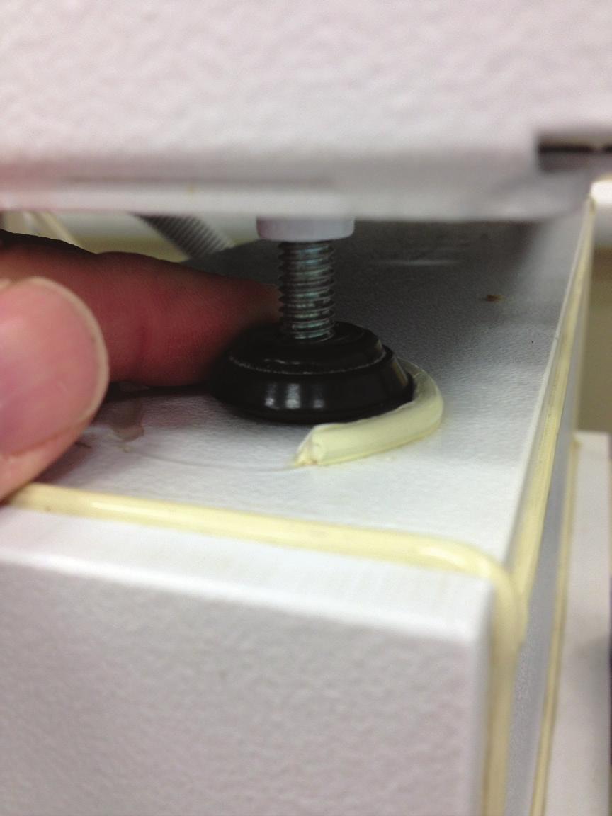
2 Figure A Figure B Figure C 2
 and 60 PSI (4.15 BAR) for proper operation.")
3 4 WATER SUPPLY 1. Attach one end of the stainless steel hose to the blue water connection labeled Water Inlet located on the back of the reprocessor. 2. Attach the other end of the stainless steel hose to the output T fitting of the water filter housing. 3. The water pressure must be between 40PSI (2.75 BAR) and 60 PSI (4.15 BAR) for proper operation. If the incoming water pressure is outside of this range, consult a qualified plumber to obtain the optimal pressure. Water Inlet Connection Figure 1: CER OPTIMA Reprocessor Back Panel Attach one end of the stainless steel hose here Water outlet to CER OPTIMA reprocessor Incoming water connection Figure 2: Water Filter System 3

4 5 DRAIN Attach the flexible drain hose to the back of the reprocessor to the port labeled DRAIN. Use a hose clamp to secure the hose to the drain. Note: The drain hose must not loop up higher than the drain connection. Confirm there are no loops in the drain hose, and that it has a constant slope to the facility drain. The drain hose requires an air gap at the point it enters the facility drain. Note: Never use a dishwasher attachment to the sink drain, refer to Figure 3. Figure 3: Drain configuration 4
 per minute. 3. Eliminate all loops in the drain hose to allow proper fluid draining, refer to figure 4.")
5 Drain requirements: 1. The facility drain must be at least 12 inches (30 cm) below the drain fitting on the reprocessor. 2. The drain must be capable of handling a discharge rate of 5 gallons (19L) per minute. 3. Eliminate all loops in the drain hose to allow proper fluid draining, refer to figure An open drain provides the best drain air gap and flow conditions. 5. Never use a dishwasher type drain attachment connected to the trap of a sink. This will result in poor machine draining and potential system alarms conditions. Incomplete draining could also result in dilution of the disinfectant chemistry or inadequate endoscope rinsing, refer to figure 3. Figure 4: 5
6 6 ELECTRICAL 1. Electrical Cord: For all CER OPTIMA reprocessor models, plug the hospital-grade electrical cord FIRMLY into the power entry module located on the right side of the reprocessor (see Figure 5). Plug the other end into a power outlet having a Ground Fault Interrupter (GFI), or Residual Current Device (RCD). Power cord in power entry module Figure 5: CER OPTIMA Power Entry NOTE: For maximum safety, MEDIVATORS recommends the CER OPTIMA system only be used when connected to an electrical outlet containing a Ground Fault Interrupter (GFI), or Residual Current Device (RCD). NOTE: MEDIVATORS recommends surge protectors be used for protection against electrical power spikes and surges. Consult local electrical codes to ensure proper compliance. 6
 The reservoir can be installed: 1. Under a counter 2.")
7 7 DRAIN SCREEN Make sure that the drain screen is in place (Remove the tape used for shipping). Drain screen Figure 6: CER OPTIMA Reprocessor Basin 8 HLD RESERVOIR (High-level Disinfectant Reservoir) The reservoir can be installed: 1. Under a counter 2. In the bottom of the cart CAUTION: Do not place the disinfectant reservoir on the same level as the CER OPTIMA reprocessor. The top of the disinfectant reservoir must be lower than the bottom of the CER OPTIMA reprocessor. NOTE: It is imperative the elbow connector must be connected to the back of the reprocessor and not the reservoir. Failure to do so will prevent disinfectant from being drawn up into the reprocessor. 7

8 Typical placement of a reservoir in the CER OPTIMA cart with water filters Figure 7: CER OPTIMA Cart with Reservoir and Filtration System 3. Connect the disinfectant reservoir tubing having the right-angled connector and the contained disinfectant filter, to the connection point labeled "Chemical Inlet" located on the reprocessor's back panel. Connect the other end having the straight connector to any one of the mating disinfectant reservoir connectors. The order does not matter in how the hoses are connected. 4. Connect the disinfectant reservoir tubing having the right-angled connector and no disinfectant filter, to the connection point labeled "Chemical Return" located on the reprocessor's back panel. Connect the other end having the straight connector to any one of the mating disinfectant reservoir connectors. 5. Using the supplied plug, block off the unused connection point located on the disinfectant reservoir. 9 AIR FILTER The CER OPTIMA reprocessor utilizes a 0.2 micron air filter to block any air-borne bacteria from entering the endoscope during the air purge step of the reprocessing cycle. The filter can be mounted in two different configurations. 1. The air filter is attached directly to the AIR FILTER connection located on the back of the reprocessor. See Figure The air filter connection tubing is attached to the AIR FILTER connection located on the back of the machine, and then the air filter is connected to the end of the tubing. This allows the air filter to be positioned to a more user-accessible position for access and replacement. See Figure The air filters "white" connection will attach to the "white" mating connector of the machine or the air filter connections tubing. The air filters "blue" connection is then open to air (nothing is connected to it). 8

9 Air filter attached directly to machine Figure 8: Air Filter Direct Connection Barcode scanner connection Air filter hose; filter attached at other end (not in photo) Figure 9: Air Filter Tubing Connection 10 BAR CODE READER The CER OPTIMA reprocessor is equipped with a barcode reader used for scanning and recording specific information including; Endoscope ID, Operator ID, Patient ID, and Physician ID. The barcode reader is positioned in a holder which is mounted on the right side of the reprocessor. 1. Using a Phillips screw driver, attach the mounting bracket using the two mounting screws. See Figure Plug the barcode reader s electrical connector into the port labeled BARCODE located on the back panel of the CER OPTIMA unit. See Figure 9. 9

10 Barcode scanner mounting position Figure 10: CER OPTIMA Barcode Reader FILLING THE HIGH-LEVEL DISINFECTANT (HLD) RESERVOIR Refer to the CER OPTIMA User Manual (p/n ) for instructions on filling the disinfectant reservoir. 1. For the CER-1 OPTIMA model, add four gallons of HLD. 2. For the CER-2 OPTIMA model, add five gallons of HLD 3. Verify the HLD is filled up to or slightly above the correct disinfectant reservoir level mark, for the specific CER OPTIMA model in use. RESERVOIR ELECTRICAL (If using heated HLD) 1. Connect the electrical cord FIRMLY into the power entry module located on the front of the reservoir. Plug the other end into a wall outlet. 2. Turn the reservoir power switch to ON. The switch is located on the front of the heated reservoir. 3. Set the reservoir temperature display to the appropriate temperature for the HLD in use. Please note the temperature indicated on the display is the set temperature; verify the actual reservoir temperature by checking the dial thermometer located on the top of the reservoir. 4. The red light on the reservoir controller will illuminate when the reservoir is heating. Verify the reservoir is filled to the proper volume level based on the CER OPTIMA model in use. 5. Depending on the amount of fluid and the required temperature of HLD, the reservoir may take up to two hours to reach operating temperature. NOTE: For maximum safety, MEDIVATORS recommends the CER OPTIMA system only be used when connected to an electrical outlet containing a Ground Fault Interrupter (GFI), or Residual Current Device (RCD). NOTE: MEDIVATORS recommends surge protectors be used for protection against electrical power spikes and surges. Consult local electrical codes to ensure proper compliance. 10


11 13 ALCOHOL The CER OPTIMA unit has a compartment that houses the alcohol bottle, which is located on the front left-hand side of the CER OPTIMA unit and is labeled ALCOHOL. To open the alcohol compartment, press in on the small door indentation and then release; the door will now pop open slightly. Open the door fully to reveal alcohol bottle. The alcohol bottle should be checked daily as part of the Quality Assurance Test, and refilled or replaced if low. The alcohol compartment is designed to allow the use of round or oblong sized 500ml volume alcohol bottles. Only use 70% Ethyl Alcohol or Isopropyl Alcohol for end-of-cycle endoscope drying. See Figure 11. Figure 11: CER OPTIMA Alcohol Compartment 14 PRINTER Open the printer door and insert a new roll of thermal printer paper. The paper must be placed into the printer compartment so that the leading edge comes off the top of the roll. Pull a short length of paper from the roll and then gently close the printer door. Refer to Figure 12. Additional paper can be ordered using part number , which is a package of five rolls. Printer: Lift cover to insert paper Figure 12: CER OPTIMA Printer 11
12 TESTING THE REPROCESSOR Use this procedure for initially testing the CER OPTIMA system, immediately after installation setup. Refer to the CER OPTIMA user manual for detailed instructions on operating the CER unit, and to perform an endoscope reprocessing cycle. POWER Press the power switch located on the right side of the CER OPTIMA reprocessor to ON. The CER unit will now power up. SETTING DATE AND TIME The lights on the FULL, HLD/RINSE and MANUAL buttons must be OFF. Press until the following is displayed: SET DATE 01/01/12 Press to change the date Once the proper date is selected, press SET MONTH MONTH =01 Press to change the month. Once the proper month is selected, press SET DAY Day =01 Press to change the day. Once the proper day is selected, press SET YEAR Year =2012 Press to change the year. Once the proper year is selected, press SET TIME 15:54 Press to change the time. Once the proper time is selected, press SET HOUR Hour = 15 Press to change the hour. Once the proper hour is selected, press SET MINUTES MINUTES= 54 Press to change the minutes. Once the proper minutes is selected, press press until you exit the menu options 12
13 18 19 SETTING AC LINE FREQUENCY The CER OPTIMA AC Line frequency must be set to the frequency of the country. If not set correctly, the cycle time information displayed will be inaccurate. Place the CER OPTIMA unit into an idle state, deselect/shut off the AUTOMATIC FULL and HLD/RINSE touch pads, and also the four MANUAL touch pads, so their respective green lights are OFF. 1. Press until SERVICE MENU is displayed 2. Press to toggle between 50 and 60 Hz. When the appropriate AC Line Frequency is displayed, press ENTER. 3. Press the until back to the main menu. SETTING THE DISINFECTANT TYPE The CER OPTIMA reprocessor has preset programming based on the type of disinfectant used. Disinfectant options Confirm the CER OPTIMA reprocessor is configured to run aldehyde-based HLD only: configure the unit if necessary. Selecting the correct HLD type will set the pre-programmed contact time, use temperature and required rinse cycles. Set the HLD reservoir temperature a minimum of two degrees higher than the minimum required use temperature for the selected HLD. NORTH AMERICAN MINIMUM AND MAXIMUM ALARM PARAMETERS DISINFECTANT TYPE Minimum Temp alarm HLD Contact Time Number of Rinses Maximum Temp alarm RAPICIDE Disinfectant 35 C 5 min 2 40 RAP OPA28H 25 C 5 min 2 40 RAP OPA28U 20 C 10 min 2 40 OPA 20 C 12 min 3 40 GLUT 20 C 20 Min 2 40 GLUT 25 C 20 Min 2 40 GLUT 20 C 45 min 2 40 INTERNATIONAL MINIMUM AND MAXIMUM ALARM PARAMETERS DISINFECTANT TYPE Minimum Temp alarm HLD Contact Time Number of Rinses Maximum Temp alarm RAP OPA INT 20 C 5 min


14 To Change the Disinfectant Type: 1. Place the CER OPTIMA reprocessor into an idle state, deselect/shut off the AUTOMATIC FULL and HLD/ RINSE touch pads, and also the four MANUAL touch pads, so their respective green lights are OFF. 2. Press the arrow until SERVICE MENU is displayed. 3. To access the SERVICE MENU, press and hold the arrow and then press the arrow. 4. The current programmed disinfectant type will now appear on the screen. NOTE: From the factory default is for RAPICIDE Disinfectant For North America: Proceed to line 5. For International: Press the arrow key one time and INT L DISINFECTANT should be displayed. Press the arrow until the desired disinfectant type is displayed. Proceed to step Press the arrow until the desired disinfectant type is displayed. 6. Press ENTER to select the disinfectant: the CER OPTIMA reprocessosr is now programmed to this disinfectant WATER 1. Connect the water supply hose to the input of the water filtration system. Refer to Figure Slowly open the water supply valve to the water filtration system. 3. Check for leaks on the water filtration unit and all the hose connections to the CER OPTIMA reprocessor. No water should be entering the unit at this point. If so, then turn the power OFF and contact Medivators Technical Support. DRAIN Verify the CER OPTIMA drain hose is attached to the facility drain. Periodically check during the CER test cycle for leaks in the drain line system. INSTALLATIONS OF DRAIN SCREEN AND DRAIN COVER 1. Install the drain screen into the drain, see Figure 13. This screen must be cleaned daily. Refer to the operations manual for details. 2. Place the drain cover over the drain screen. This cover prevents the endoscope from blocking the drain. See Figure 14. Figure 13 Figure 14 14
15 23 QUALITY ASSURANCE TEST Refer to the CER OPTIMA User Manual (p/n ) for instructions on performing the Daily Quality Assurance Test (QA Test). Run and successfully complete the QA test OPERATION Refer to the CER OPTIMA User Manual (p/n ) for instructions on proper use and operation of the CER OPTIMA automated endoscope reprocessor. NOTE: The CER OPTIMA reprocessor configured disinfectant type will display on the CER screen during the Automatic reprocessing cycle. FINAL TEST Upon successful completion of the Quality Assurance Test, perform an Automatic HLD/Rinse cycle. 1. Select the AUTOMATIC HLD/RINSE cycle. 2. Press START to begin the cycle. 3. While the system is filling with water, observe the dynamic pressure readings on the three pressure gauges located on the water filtration system. The pressure on the incoming pressure gauge #1 should read between 40PSI (2.75BAR) and 60PSI (4.15BAR). Gauges #2 and #3 should be within 5PSI (0.35BAR) of the incoming water pressure gauge # 1. If the incoming water pressure is not within the 40-60PSI ( BAR) range, the reprocessor may experience an alarm condition and/or premature component failure due to low incoming water flow. Refer to a qualified plumber to correct the incoming water pressure to meet the specifications of the machine. See Figure

16 Gauge #3 Gauge #2 Gauge #1 Water output to the reprocessor Water input Figure 15: Water Filtration System Gauges 4. When the CER OPTIMA basin is almost full, observe the overflow drain located on the top left portion of the basin. No fluid should go down the overflow drain at this point of the cycle. If it does, the CER OPTIMA unit may not be level. Re-adjust the legs of CER OPTIMA unit until the water level is even around the top of the basin. If fluid level indicates the reprocessor is not level, refer back to section 3 to correct the machine level. See Figure

17 Overflow drain. In normal operations, no fluid should go down this drain Figure 16: CER OPTIMA Reprocessor Overflow Drain 5. If the AUTOMATIC HLD/RINSE cycle completes without errors or leaks, then run two additional error-free reprocessing cycles. Once all test cycles are completed, perform the waterline disinfection step, as outlined in the CER OPTIMA USERS MANUAL. 6. Once all of the above steps are completed, the CER OPTIMA system is ready to be placed into service. MEDIVATORS, RAPICIDE and CER OPTIMA are registered trademarks of Medivators Inc. Medivators Website Resource Center Go to: Select Resource Center and User Library for detailed user guides and hookup information, report forms and logs, and product bulletins MEDIVATORS Customer and Technical Support Toll Free: Phone: FAX:
18 Manufactured in the USA by: Medivators Inc th Avenue North Minneapolis, MN USA Toll Free: Medivators BV Sourethweg PC Heerlen The Netherlands Tel: Cantel Medical Asia/Pacific Pte. Ltd. 1A International Business Park #05-01 Singapore Tel: Medivators Inc. Beijing Representative Office Room 1801, Floor 18th, Tower A, Beijing Marriott Hotel, Office Building No. 7, Jianguomen South Avenue, Dongcheng District, Beijing China Tel: Medivators Inc. All rights reserved /E 18
Endoscope Reprocessor Installation Instructions Endoscope Reprocessing System
 Endoscope Reprocessor Installation Instructions Endoscope Reprocessing System Introduction The following document outlines the installation procedure for the CER 1 and CER 2 reprocessor(s). Please refer
CER-1 & CER-2 Site Requirements
 CER-1 & CER-2 Site Requirements 1 2 INTRODUCTION The following document outlines the space requirements, water supply, drain and electrical specifications required for the installation of the MEDIVATORS
CER OPTIMA. Endoscope Reprocessing System CER-1 & CER-2 Site Requirements. Introduction. Space Requirements
 CER OPTIMA Endoscope Reprocessing System CER-1 & CER-2 Site Requirements 1 1 2 Introduction The following document outlines the space requirements, water supply, drain and electrical specifications required
Customer Requirements Pre-Installation Instructions
 Customer Requirements Pre-Installation Instructions This document provides the facility with requirements to ensure correct installation and subsequent proper performance of a DSD EDGE Endoscope Reprocessing
SITE REQUIREMENTS & INSTALLATION DSD-201 & SSD-102
 Instructions SITE REQUIREMENTS & INSTALLATION DSD-201 & SSD-102 The purpose of this section is to provide the customer with requirements that need to be met before the DSD/SSD can be properly installed.
Site Requirements. MODEL 2.0 Australia
 Site Requirements MODEL 2.0 Australia 1 ADVANTAGE PLUS, MEDIVATORS and RAPICIDE are registered trademark of Medivators Inc. WINDOWS and WINDOWS 7 are registered trademarks of Microsoft Corporation. 50098-608
Water Pre-Filtration System Installation Instructions Endoscope Reprocessing Systems
 Water Pre-Filtration System Installation Instructions Endoscope Reprocessing Systems DSD-201LT, DSD EDGE, SSD-102LT WARNING: DO NOT over-tighten filter housings (hand-tighten only). Over tightening will
Plumbing fittings should be hand tightened followed by one complete turn with the appropriate wrench.
 WATER PRE-FILTRATION SYSTEM INSTALLATION INSTRUCTIONS DSD-201, DSD EDGE, SSD-102 WARNING: DO NOT over-tighten filter housings (hand-tighten only). Over tightening will result in failure of the pre-filter
CER OPTIMA. Service Manual. Endoscope Reprocessing System. CER OPTIMA Service Manual
 CER OPTIMA Endoscope Reprocessing System Service Manual CER OPTIMA Service Manual 1 50098-027 Rev B 1.20.2014 2014 MEDIVATORS Inc. All rights reserved. This publication is protected by copyright. Copying,
SITE REQUIREMENTS 1 USER MANUAL INSTALLATION PACKAGE SITE REQUIREMENTS
 SITE REQUIREMENTS 1 USER MANUAL INSTALLATION PACKAGE SITE REQUIREMENTS 2 SITE REQUIREMENTS ADVANTAGE PLUS is a registered trademark of Medivators Inc. All company or product names referenced are trademarks
CER-1 / CER-2 (MV-1 / MV-2) (CLM-5001X / CLM-5002VX)
 (CLM-5001X / CLM-5002VX)") CER-1 / CER-2 (MV-1 / MV-2) (CLM-5001X / CLM-5002VX) Endoscope Reprocessor User / Service Manual 2016 Medivators Inc. All rights reserved. Printed in the United States of America The following trademarks
CER-1 / CER-2 (MV-1 / MV-2) (CLM-5001X / CLM-5002VX) Endoscope Reprocessor User / Service Manual 2016 Medivators Inc. All rights reserved. Printed in the United States of America The following trademarks
Site Requirements ADVANTAGE PLUS
 Site Requirements ADVANTAGE PLUS Reprocessing System MODEL 2.0 International 1 MEDIVATORS is a registered trademark. MEDIVATORS ADVANTAGE is a trademark of MEDIVATORS Inc. Windows and Windows XP are registered
MODEL 7000 SUCTION UNIT
 MODEL 7000 SUCTION UNIT OPERATOR S MANUAL Caution Federal law restricts this device to sale by or on order of a physician, or any other practitioner licensed by the law of the State in which he practices
Schuco byallied MEDICAL ASPIRATOR. USER'S MANUAL A Caution
 S168-544-OO1E REV.A Schuco byallied MEDICAL ASPIRATOR MnrInI -33OA USER'S MANUAL A Caution Federal law restricts this device to sale by or on order of a physician, or any other practitioner licensed by
GROWMAX WATER Perfect Water for Plants and Gardens
 GROWMAX WATER Perfect Water for Plants and Gardens WATER SYSTEMS FOR HYDROPONICS AND GARDENING GROWMAX 3000 Ultra-Pure Reverse Osmosis Water System Up to 3000 L/D of Pure Water Don't forget to register
PRF-RO Pentair Reverse Osmosis System Installation and Maintenance Manual SAFETY GUIDES THE BASIC REVERSE OSMOSIS SYSTEM. Tools and Materials Required
 PRF-RO Pentair Reverse Osmosis System Installation and Maintenance Manual SAFETY GUIDES Read and follow all steps and guides carefully before installing and using your reverse osmosis system. Do not use
BUILT-IN DISHWASHER INSTALLATION INSTRUCTIONS
 BUILT-IN DISHWASHER INSTALLATION INSTRUCTIONS PLEASE READ COMPLETE INSTRUCTIONS BEFORE YOU BEGIN LEAVE INSTALLATION INSTRUCTIONS AND USER'S GUIDE WITH OWNER ALL ELECTRIC WIRING AND PLUMBING MUST BE DONE
OPERATING MANUAL/ INSTALLATION
 NHW- 15 HOT WATER MACHINE OPERATING MANUAL/ INSTALLATION 120/240 V 1650/6600 W US 120/240 V 1350/5500 W CAN CONVERTIBLE 2 GA LLON DRIP TRAY INCLUDED ADVANCED TEMPERATURE CONTROL TVT TECHNOLOGY NEWCO ENTEPRISES
Operator s Manual. Model G17-EU (International) Disinfection Soak Station for Hysteroscopes, Cystoscopes and ENT scopes
 Disinfection Soak Station for Hysteroscopes, Cystoscopes and ENT scopes") Model G17-EU (International) Disinfection Soak Station for Hysteroscopes, Cystoscopes and ENT scopes Operator s Manual CIVCO Medical Solutions 102 First Street South Kalona, IA 52247 USA Tel: 1-800-445-6741
Model G17-EU (International) Disinfection Soak Station for Hysteroscopes, Cystoscopes and ENT scopes Operator s Manual CIVCO Medical Solutions 102 First Street South Kalona, IA 52247 USA Tel: 1-800-445-6741
Installation Instructions
 GE Consumer & Industrial Appliances Installation Instructions Junction Box Cover Within this user bag, you will find a junction box cover and a #10 hex head screw used to attach the junction box cover
Owner's Manual. WS Series. Water Softener
 Owner's Manual WS-165-150 Series Water Softener Table of Contents WHAT'S INCLUDED 3 OPERATING CONDITIONS 4 ASSEMBLY INSTRUCTIONS 6 FLUSHING THE WATER LINES 13 MASTERPROGRAMMING 14 PROGRAMMING KEYAND GENERAL
Guide, Quick Start, Short, X-100 System
 Rev. CR/CO Date Orig. A 9950 2/15/16 DH Guide, Quick Start, Short, X-100 System P/N LANGUAGE NONIN ELECTRONIC FILE FINALSIZE 10885-001 ENGLISH 10885-001.01.INDD 5.5 X 8.5 NOTE 1: a. MATERIAL: 100lb cover
Top Control Dishwasher
 INSTALLATION GUIDE Top Control Dishwasher NS-DWH2BS8/NS-DWH2SS8/NS-DWR2BS8/NS-DWR2WH8/NS-DWR2SS8 Before using your new product, please read these instructions to prevent any damage. Contents Introduction......................................................................................................
Installation Instructions. For the 18 Built-In Dishwasher and Front Color Panels
 Installation Instructions For the 18 Built-In Dishwasher and Front Color Panels Printed in USA 154232102 Before You Begin DO NOT INSTALL DISHWASHER UNTIL YOU HAVE READ ALL INSTRUCTIONS. FOR YOUR SAFETY,
2015 Myco Industries, Inc Fax:
 Endoscope Cleaning and Handling It is highly important that you manually clean the endoscope immediately after it is removed from the patient, BEFORE it is automated or manually disinfected. Cleaning your
Fleck 5600 Carbon Filter Installation & Start Up Guide
 Clean Water Made Easy www.cleanwaterstore.com Fleck 5600 Carbon Filter Installation & Start Up Guide Thank you for purchasing a Clean Water System! With proper installation and a little routine maintenance
1-866-PENNERS
 Cascade Premier and Elite Premier Bathing Systems with Aqua-Aire Installation / Assembly Instructions Premier Elite Premier PENNER PATIENT CARE, INC Box 523 / 102 Grant St. Aurora, NE 68818 360745P Revision
Chemical Transfer Pump Tube Set and Adapter Instructions
 Caution: Use personal protective clothing when transferring Liquid Chemical Germicide (LCGs). 1. Recommended Filling Method. Figure 1. TP-1 Transfer Pump DSD-1087 110VAC DSD-1088 220VAC a. Plug the Transfer
Electrical cable Water supply tube Fittings for tube Coupler Teflon tape. Hole saw min. 2½" bit
 Installation Parts and Tools Parts not Provided Electrical cable Water supply tube Fittings for tube Coupler Teflon tape Air gap Wire nuts for 6-gauge wiring Hose clamp ⅞" UL approved strain relief Electrical
Enteral Pump Instructions for Use To Assemble When the low
 Enteral Pump Instructions for Use Before initial use on battery power and after extended storage periods, the pump must be plugged into an AC power source for a minimum of 12 hours (pump may be operated
ON TRACK Reprocessing In-service / Competency for CF/PCF/GIF Endoscopes (EVIS, EXERA, EXERA II)
") THIS CHECKLIST IS DESIGNED FOR USE SOLELY AS A CUSTOMER EDUCATIONAL TOOL, AND IS NOT INTENDED TO REPLACE OR ANY WAY MODIFY THE OLYMPUS INSTRUCTION MANUAL/REPROCESSING MANUAL. BE SURE TO FOLLOW THE DETAILED
THIS CHECKLIST IS DESIGNED FOR USE SOLELY AS A CUSTOMER EDUCATIONAL TOOL, AND IS NOT INTENDED TO REPLACE OR ANY WAY MODIFY THE OLYMPUS INSTRUCTION MANUAL/REPROCESSING MANUAL. BE SURE TO FOLLOW THE DETAILED
5700-E Sediment Filter Installation & Start-Up Guide
 Clean Water Made Easy www.cleanwaterstore.com 5700-E Sediment Filter Installation & Start-Up Guide Thank you for purchasing a Clean Water System! With proper installation and a little routine maintenance
INSTALLATION AND OPERATION MANUAL STEAM COIL BASE CONVECTION STEAMER MODEL SCX-16
 INSTALLATION AND OPERATION MANUAL STEAM COIL BASE CONVECTION STEAMER MODEL SCX-16 CROWN FOOD SERVICE EQUIPMENT LTD. 70 OAKDALE ROAD, DOWNSVIEW, (TORONTO), ONTARIO, CANADA, M3N 1V9 TELEPHONE: (416) 746-2358,
1. BYPASS 7. WATER OUTLET 2. VALVE HOUSING 8. BLENDING REGULATOR 3. RESIN TANK 9. HARDNESS REGULATOR 4. SALT BIN 10.
 INSTALLATION GUIDE SIMPLEX EXTERNAL 1. Parts: 1. BYPASS 7. WATER OUTLET 2. VALVE HOUSING 8. BLENDING REGULATOR 3. RESIN TANK 9. HARDNESS REGULATOR 4. SALT BIN 10. TO BRINE VALVE 5. BRINE VALVE (floater)
INSTALLATION GUIDE. soft duomatik evoline
 INSTALLATION GUIDE soft duomatik evoline Before introduction of the softener the installation guide has to be read carefully. For any disturbances cause by disregarding the instructions evo-water doesn
DISHWASHER INSTALLATION GUIDE SPECIFICATIONS, INSTALLATION, AND MORE
 DISHWASHER INSTALLATION GUIDE SPECIFICATIONS, INSTALLATION, AND MORE COVE DISHWASHER Contents 3 Cove Dishwasher 4 Specifications 7 Door Panel 9 Installation 15 Troubleshooting Features and specifications
Spa Touch Control Panel with BP2100, BP6013 spa controllers. (Spa Owner s Manual insert)
") Spa Touch Control Panel with BP2100, BP6013 spa controllers. (Spa Owner s Manual insert) P.N. 7876C (export) February 12, 2015 For Spas equipped with BP2100, BP6013 controllers and Spa Touch panel. Spa
Spa Touch Control Panel with BP2100, BP6013 spa controllers. (Spa Owner s Manual insert) P.N. 7876C (export) February 12, 2015 For Spas equipped with BP2100, BP6013 controllers and Spa Touch panel. Spa
Installation Instructions 36 Inch Refrigerator
 Installation Instructions 36 Inch Refrigerator For Use With Models: EF36BNNF, IF36BNNF, PF36BNNF Francis - Voir Page 9 Part No. 106177 Rev. B/13036906 Refrigerator Safety...1 Proper Disposal of Your Refrigerator...1
Spa Touch Control Panel with 2000, 2100 controllers. (Spa Owner s Manual insert)
") Spa Touch Control Panel with 2000, 2100 controllers (Spa Owner s Manual insert) P.N. 7876B February 11, 2015 For Spas equipped with BP2000, BP2100 controllers and Spa Touch panel. Spa Touch Control Panel
Spa Touch Control Panel with 2000, 2100 controllers (Spa Owner s Manual insert) P.N. 7876B February 11, 2015 For Spas equipped with BP2000, BP2100 controllers and Spa Touch panel. Spa Touch Control Panel
Built-In Dishwasher. Installation Instructions. BEFORE YOU BEGIN Read these instructions completely and carefully. IMPORTANT The dishwasher MUST be
 Installation Instructions Built-In Dishwasher If you have questions, call 800.GE.CARES (800.432.2737) or visit our website at: www.ge.com BEFORE YOU BEGIN Read these instructions completely and carefully.
FI DISHWASHER INSTALLATION INSTRUCTIONS
 FI DISHWASHER INSTALLATION INSTRUCTIONS IMPORTANT! Read all of these instructions before installing the dishwasher. CONTENTS AUTOMATIC HIGH LOOP The drain hose is fastened to the back of the machine at
7800 Neutralizer Installation & Start-Up Guide
 Clean Water Made Easy www.cleanwaterstore.com 7800 Neutralizer Installation & Start-Up Guide Thank you for purchasing a Clean Water System! With proper installation and a little routine maintenance your
Installation Instructions Built-In Dishwasher
 RINSE CHINA CRYSTAL SPEED CYCLE NORMAL WASH COOK WARE SELECTIONS ANTI BACTERIA START RESET ENHANCEMENTS DELAY HOURS ADDED HEAT PRE WASH HEATED DRY TO LOCK CONTROLS PRESS HEATED DRY FOR 3 SECONDS GE Consumer
PRE-ASSEMBLED RADIANT CONTROL PANEL INSTALLATION MANUAL
 FloorHeat PRE-ASSEMBLED RADIANT CONTROL PANEL INSTALLATION MANUAL Thank you for purchasing this radiant control panel assembly. Following are some important notes that will make the installation successful.
Clean Water Made Easy
 Clean Water Made Easy http://www.cleanwaterstore.com Pro-OX 1650 Iron Filter Installation & Start-Up Guide Thank you for purchasing a Clean Water System! With proper installation and a little routine maintenance
5000 Series Bottled Water System by.
 www.xylemflowcontrol.com 2015 Xylem Inc. All rights reserved. Flojet is a trademark of Xylem Inc. or one of its subsidiaries. 81000453 Rev A. 04/2015 5000 Series Bottled Water System by HOW THE SYSTEM
Cascade Premier and Elite Premier Bathing Systems with Aqua-Aire Installation / Assembly Instructions
 Cascade Premier and Elite Premier Bathing Systems with Aqua-Aire Installation / Assembly Instructions Premier Elite Premier PENNER PATIENT CARE, INC Box 523 / 102 Grant St. Aurora, NE 68818 360745P Revision
Operator s Manual. Model G32-S Model G32-E Disinfection Soak Stations
 Model G32-S Model G32-E Disinfection Soak Stations Operator s Manual CIVCO Medical Solutions 102 First Street South Kalona, IA 52247 USA Tel: 1-800-445-6741 Fax: 1-877-329-2482 Website: WWW.CIVCO.COM Copyright
Operator s Manual. Model G14TC-3 Disinfection Soak Station for Transesophageal Ultrasound Probes
 Model G14TC-3 Disinfection Soak Station for Transesophageal Ultrasound Probes Operator s Manual CIVCO Medical Solutions 102 First Street South Kalona, IA 52247 USA Tel: 1-800-445-6741 Fax: 1-877-329-2482
SOLUSCOPE SERIES 3 DESIGNED WITH THE FUTURE IN MIND FEATURES FLEXIBLE ENDOSCOPE DISINFECTOR / STERILISER
 SOLUSCOPE SERIES 3 FLEXIBLE ENDOSCOPE DISINFECTOR / STERILISER FEATURES Sterile Cycle HLD Cycle Continuous Leak Test Channel Flow Monitoring Pre Disinfection Wash Cycle Fast Cycle Time Barcode Tracking
Installation and Use Manual
 Installation and Use Manual EMABFWS-RF and LMABFWS-RF Retrofit Bottle Filling Stations IMPORTANT THIS IS AN INDOOR APPLICATION ONLY. ALL SERVICE TO BE PERFORMED BY AN AUTHORIZED SERVICE PERSON. TOOLS REQUIRED
Installation Instructions
 Installation Instructions Built-In Dishwasher If you have questions, call 800-944-9400(US),800-245-8352(Canada)or visit our website at: www.frigidaire.com BEFORE YOU BEGIN Read these instructions completely
APPENDIX 4. Thank you for choosing the Biomega BioClave steam sterilizer. HYDRAULIC DRAWING
 Thank you for choosing the Biomega BioClave steam sterilizer. Your steam sterilizer has been CE certified and designed with durability, reliability, and safety in mind. It is your responsibility to install
OUTDOOR DISHWASHER INSTALLATION INSTRUCTIONS
 OUTDOOR DISHWASHER INSTALLATION INSTRUCTIONS IMPORTANT! Read all of these instructions before installing the dishwasher. AUTOMATIC HIGH LOOP The drain hose is fastened to the back of the machine at the
Mix Boiler & Font Range ( #, #, #, , )
") Mix Boiler & Font Range (1000870#, 1000871#, 1000880#, 1000878, 1000879) Service Manual Marco Beverage Systems Ltd. 63d Heather Road, Sandyford Industrial Estate, Dublin 18, Republic of Ireland Ireland
Mix Boiler & Font Range (1000870#, 1000871#, 1000880#, 1000878, 1000879) Service Manual Marco Beverage Systems Ltd. 63d Heather Road, Sandyford Industrial Estate, Dublin 18, Republic of Ireland Ireland
Installation Instructions
 GE Consumer & Industrial Appliances Installation Instructions Junction Box Cover Within this user bag, you will find a junction box cover and a #10 hex head screw used to attach the junction box cover
ENDOSCOPE REPROCESSOR OER-Pro Operation Manual
 Chapter 5 End-of-Day Checks Chapter 5 End-of-Day Checks To ensure safe, reliable operation, inspect and clean all parts of the device regularly. Check Checks at the end of every working day 5.1 Turning
CWS Plus Sediment Filter Installation & Start Up Guide
 Clean Water Made Easy www.cleanwaterstore.com CWS Plus Sediment Filter Installation & Start Up Guide Thank you for purchasing a Clean Water System! With proper installation and a little routine maintenance
Attendance Sheet. (List each model reviewed during this session) Print Name Signature Title. Print Name Signature Title.
 Print Name Signature Title. Print Name Signature Title.") THIS CHECKLIST IS DESIGNED FOR USE SOLELY AS A CUSTOMER EDUCATIONAL TOOL, AND IS NOT INTENDED TO REPLACE OR ANY WAY MODIFY THE OLYMPUS INSTRUCTION MANUAL/REPROCESSING MANUAL. BE SURE TO FOLLOW THE DETAILED
THIS CHECKLIST IS DESIGNED FOR USE SOLELY AS A CUSTOMER EDUCATIONAL TOOL, AND IS NOT INTENDED TO REPLACE OR ANY WAY MODIFY THE OLYMPUS INSTRUCTION MANUAL/REPROCESSING MANUAL. BE SURE TO FOLLOW THE DETAILED
1. WARNINGS FOR YOUR SAFETY 2. TECHNICAL SPECIFICATIONS. Allowable Ambient Temperatures: Maximum Film Quantities: 3. INTRODUCTION
 Instructions for the AutoLab ATL-500 #4235 and the AutoLab ATL 800 #4237 ATL-800 ATL-500 Index 1. WARNINGS FOR YOUR SAFETY 2. TECHNICAL SPECIFICATIONS Allowable Ambient Temperatures: Maximum Film Quantities:
IMPORTANT INFORMATION. Revised Dishwasher Installation Instructions
 IMPORTANT INFORMATION Revised Dishwasher Installation Instructions To obtain a revised copy of the entire Dishwasher User s Manual, go to www.eurotechappliances.com. SPECIAL EDITION 11-20-02 SAVE THESE
Installation Instructions
 Installation Instructions For the 18" Built-In Dishwasher Sears, Roebuck and Co. Sears Canada, Inc. Hoffman Estates, IL 60179 U.S.A. Toronto, Ontario, Canada M5B 2B8 154435201 Before You Begin DO NOT INSTALL
INSTALLATION INSTRUCTIONS UNDERCOUNTER DISHWASHERS
 INSTALLATION INSTRUCTIONS UNDERCOUNTER DISHWASHERS VIKING 111 Front Street Greenwood, Mississippi 38930 USA (662) 455-1200 IMPORTANT - PLEASE READ AND FOLLOW Before beginning - please read these instructions
Use and Care Guide. Over the Patient Units and Swing Mount Units
 Over the Patient Units and Swing Mount Units Table of Contents Page General Information 2 Operation 3-5 Dental Unit Adjustments 6-10 Cleaning, Disinfecting and Sterilization 11-12 Maintenance 13-15 Page
DOUBLE DISHDRAWER TM DISHWASHER
 DOUBLE DISHDRAWER TM DISHWASHER DD4DDFT & DD4DVT models INSTALLATION GUIDE US CA 5985 A 08.7 SAFETY AND WARNINGS! WARNING! Electrical Shock Hazard Before installing the dishwasher, remove the house fuse
Home Medical Equipment Oxygen
 Home Medical Equipment Oxygen OhioHealth Home Medical Equipment 7708 Green Meadows Drive, Suite D Lewis Center, Ohio 43035 614-566-0850 or 1-800-300-7075 OXYGEN CONCENTRATOR 1. The On/Off switch is on
LXG-300 Series. Models with LXG-300 Series Instruments
 I.O.M. #147 updated : 08/16/2018 INSTRUCTION MANUAL INSTALLATION OPERATION MAINTENANCE LXG-300 Series Models with LXG-300 Series Instruments Model: Serial Number : 525 East Stop 18 Road Greenwood, IN 46142
INSTALLATION INSTRUCTIONS
 INSTALLATION INSTRUCTIONS TM DishDrawer dishwasher DD4S 7 & DD4ST 7 models US CA 59004D 04.3 FOLLOW THE INSTALLATION SEQUENCE RELEVANT TO YOUR MODEL STANDARD HEIGHT SINGLE MODELS TALL HEIGHT SINGLE MODELS
Transmission Cooling System J Operation Manual. TRANSFLOW Transmission Cooling System Service Tool J
 Transmission Cooling System J-45096 Operation Manual TRANSFLOW Transmission Cooling System Service Tool J-45096 1 Safety Precautions WARNING: TO PREVENT PERSONAL INJURY AND/OR DAMAGE TO EQUIPMENT: ALLOW
DISHWASHER INSTALLATION INSTRUCTIONS
 DISHWASHER INSTALLATION INSTRUCTIONS IMPORTANT! Read all of these instructions before installing the dishwasher. AUTOMATIC HIGH LOOP The drain hose is fastened to the back of the machine at the best height.
OPERATING MANUAL/ INSTALLATION
 NHW- 15 HOT WATER MACHINE OPERATING MANUAL/ INSTALLATION 120/240 V 1650/6600 W US 120/240 V 1350/5500 W CAN CONVERTIBLE 2 GA LLON DRIP TRAY INCLUDED ADVANCED TEMPERATURE CONTROL TVT TECHNOLOGY NEWCO ENTEPRISES
Parasitic Cysts - Cryptosporidium and Giardia, Chemicals, Heavy Metals, Dissolved Salts, Offensive Tastes and Odours, Sediment, Dirt,
 Aqua-Pure is a market leader in water filtration. In addition to our comprehensive range of Domestic Water Purifiers, we design and manufacture an extensive commercial and industrial range of purification
Cabinet Non-Electric Water Softener
 Cabinet Non-Electric Water Softener INSTALLATION MANUAL Table of Contents 1. Parts 3 2. Precautions 4 3. Installation 4 4. Settings 6 5. Start-up 7 6. Performance Data Sheet 10 The CABINET NON-ELECTRIC
Dishwasher Installation Instructions DW 24XT/DW 24XV
 Dishwasher Installation Instructions DW 24XT/DW 24XV Installation Instructions Dishwasher BEFORE YOU BEGIN Read these instructions completely and carefully. IMPORTANT Observe all governing codes and ordinances.
PumpLab TM Operator s Manual
 PumpLab TM Operator s Manual PumpLab TM Centrifugal Flow/ Process Control System i PumpLab TM Main Features Clear View Flow Circuit Outlet Valve Data Display/Record Flow Meter Exit Pressure Sensor Computer
1. BYPASS 7. WATER OUTLET 2. VALVE HOUSING 8. BLENDING REGULATOR 3. RESIN TANK 9. HARDNESS REGULATOR CONTAINER FOR 4.
 INSTALLATION GUIDE ESCALDA 1. Parts: 1. BYPASS 7. WATER OUTLET 2. VALVE HOUSING 8. BLENDING REGULATOR 3. RESIN TANK 9. HARDNESS REGULATOR CONTAINER FOR 4. DEVICE AND SALT 10. TO BRINE VALVE 5. BRINE VALVE
MIX Boiler & Font Range Service Manual
 MIX Boiler & Font Range Service Manual 1000870# 1000871# 1000875# 1000880# 1000887# 1000878 1000879 2300268 www.marcobeveragesystems.com Ireland Tel: +353 (1) 295 2674 UK Tel: +44 (0207) 2744577 Service
Operator s Manual. Model G17 Disinfection Soak Station for Hysteroscopes, Cystoscopes and ENT scopes
 Model G17 Disinfection Soak Station for Hysteroscopes, Cystoscopes and ENT scopes Operator s Manual CIVCO Medical Solutions 102 First Street South Kalona, IA 52247 USA Tel: 1-800-445-6741 Fax: 1-877-329-2482
Installation Manual PS-225 & PS-275
 Installation Manual PS-225 & PS-275 Table of Contents Pre-Uncrating Checklist... 1 Verifying System Requirements... 2 Verifying System Direction... 2 Verifying the Electrical Requirements... 2 Removal
MINIMED 670G SYSTEM CHANGING THE MINIMED MIO INFUSION SET QUICK REFERENCE GUIDE
 START HERE Wash your hands. Select Reservoir & Tubing. Press. Select Options. Select New Reservoir. Remove the infusion set you have been using by loosening the adhesive and pulling away from body. Remove
INSTALLATION INSTRUCTIONS
 INSTALLATION INSTRUCTIONS TM DishDrawer dishwasher DD36SDFTX (Designer) & DD36STI (Integrated) models US CA 59008D 04.3 a SAFETY AND WARNINGS Electrical hazard WARNING! Before installing the dishwasher,
BOTTLED WATER DISPENSER DISPENSADOR DE AGUA EMBOTELLADA
 BOTTLED WATER DISPENSER DISPENSADOR DE AGUA EMBOTELLADA Line to Refrigerator Ice/Water Dispenser Pump Module Dispenser www.xylemflowcontrol.com Flojet is a trademark of Xylem Inc. or one of its subsidiaries.
Installation. Leveling
 Your refrigerator was packed carefully for shipment. Remove and discard shelf packaging and tape. Do not remove the serial plate. Location Do not install refrigerator near oven, radiator or other heat
INSTALLATION INSTRUCTIONS
 INSTALLATION INSTRUCTIONS DishDrawer TM dishwasher DD24SUT7 and DD24SVT7 models US CA 590225B 04.4 SAFETY AND WARNINGS Electrical hazard WARNING! Before installing the dishwasher, remove the house fuse
Installation Instructions Built-In Dishwasher
 GE Consumer & Industrial Appliances Installation Instructions Built-In Dishwasher If you have questions, call 800.GE.CARES (800.432.2737) or visit our website at: www.ge.com BEFORE YOU BEGIN Read these
I N ST R UC T I ON MODEL 2612 & 2712 SLICERS MODELS 2612 ML ML FORM (12-98) 2612 SLICER
 2612 SLICER") I N ST R UC 2612 SLICER T I ON S MODEL 2612 & 2712 SLICERS MODELS 2612 ML-104829 2712 ML-104822 701 S. RIDGE AVENUE TROY, OHIO 45374-0001 FORM 34141 (12-98) Installation, Operation, and Care of MODEL 2612
I N ST R UC 2612 SLICER T I ON S MODEL 2612 & 2712 SLICERS MODELS 2612 ML-104829 2712 ML-104822 701 S. RIDGE AVENUE TROY, OHIO 45374-0001 FORM 34141 (12-98) Installation, Operation, and Care of MODEL 2612
Fleck 7000 Sediment Filter Installation & Start-Up Guide
 Clean Water Made Easy www.cleanwaterstore.com Fleck 7000 Sediment Filter Installation & Start-Up Guide Thank you for purchasing a Clean Water System! With proper installation and a little routine maintenance
Installation Instructions
 Installation Instructions Built-In Dishwasher If you have questions, call 800-GECARES or visit our website at: www.geappliances.com BEFORE YOU BEGIN Read these instructions completely and carefully. IMPORTANT
Eco-Safe Digester. Installation Manual For E3 Series Digesters. Version 1.6 Published: Apr. 13, 2017
 Eco-Safe Digester Installation Manual For E3 Series Digesters Version 1.6 Published: Apr. 13, 2017 Eco-Safe Digester Installation Manual Table of Contents Preface... iv 1. Document Revision History...
PRO 2000i LOW LEVEL DEPOSITOR
 DEPOSITORS AND AUTOMATED CAKE PRODUCTION SYSTEMS PRO 2000i LOW LEVEL DEPOSITOR OPERATION AND SPARE PARTS MANUAL Serial No. PR2L- (Please quote this number when ordering spares, and making service calls)
Clean Water Made Easy. Fleck 7000 Tannin Filter Installation & Startup Guide. Questions?
 Clean Water Made Easy www.cleanwaterstore.com Fleck 7000 Tannin Filter Installation & Startup Guide For Tannin Filters with Vortech Distributor Screen Thank you for purchasing a Clean Water System! With
PR-L2466W- PA. Operating Instructions. High Performance Refrigerator PR-L2466W-PA
 Operating Instructions High Performance Refrigerator PR-L2466W- PA PR-L2466W-PA Please read these instructions carefully before using this product, and save this manual for future use. See page 11 for
WM-450-PT WM-900-PT Commercial Wall Mounted Reverse Osmosis
 WM-450-PT WM-900-PT Commercial Wall Mounted Reverse Osmosis Installation And Service Manual Watts Pure Water 1725 W. Williams Dr. C-20., Phoenix, Arizona 85027 Phone: 888-774-7405 Fax: 602-588-0356 www.wattspurewater.com
Tank, Heater, and Control Operation Manual REV. E DATE: 04May2015
 Tank, Heater, and Control Operation Manual 25-710-804 REV. E DATE: 04May2015 Hanson Research Corporation 9810 Variel Avenue Chatsworth, CA 91311 USA (800) 821-8165 (818) 882-7266 FAX (818) 882-9470 www.hansonresearch.com
OPERATION and MAINTENANCE INSTRUCTION MANUAL. ADU-12 Task Force Pneumatic Portable Dental System
 OPERATION and MAINTENANCE INSTRUCTION MANUAL ADU-12 Task Force Pneumatic Portable Dental System TABLE OF CONTENTS: Package Contents....................1 Introduction.........................2 Setting Up
Hoshizaki America, Inc.
 Hoshizaki America, Inc. Self-Contained Flaker Model F-330BAH(-C) A Superior Degree of Reliability INSTRUCTION MANUAL www.hoshizaki.com Issued: 5-4-2007 Revised: 1-15-2013 WARNING Only qualified service
IMPORTANT SAFETY INFORMATION READ ALL...
 INSTALLATION and SERVICE MANUAL HOUSEPURE MODELS HP03 and HP04 736-0137 Table of Contents IMPORTANT SAFETY INFORMATION READ ALL... 3 P/N 41482 Rev A 06/04 INSTRUCTIONS BEFORE USING... 3 FEEDWATER... 4
Paragon PW750F two stage Drinking Water Filtration System Installation & Operation Manual
 Paragon PW750F two stage Drinking Water Filtration System Installation & Operation Manual Marketed & Distributed in Singapore by: Quantum Impact Pte Ltd (UEN 201014570H) Add:16 Raffles Quay, #41-07, Hong
HWD-2110 Hot Water Dispenser
 User s Guide t f Touch Function Selector Technology HWD-2110 Hot Water Dispenser. NOTICE TO INSTALLER: Please leave this book with the machine. Temperature On Demand US design patent applied for. Other
What to expect from your water softener
 What to expect from your water softener All water softeners work on the same basic principal. Hard water flows through a bed of resin and the calcium and magnesium, the minerals that are responsible for