Installation Instructions & Owner's Manual. IM & INT Series
|
|
|
- Arline Richards
- 6 years ago
- Views:
Transcription
 693-1972 Fax: (260)693-0602 www.")
1 Installation Instructions & Owner's Manual IM & INT Series US Highway 33 N. Churubusco, IN Phone: (260) Fax: (260)
2 TABLE OF CONTENTS: Preinstallation Instructions for Dealers Page 3 Bypass Valve Page 3-4 Installation Page 5-6 Programming Procedures for Water Softeners Page 7-8 Operating Displays for Softeners Page 9 Start-up Instructions Page 10 Troubleshooting Guide Page Component List Page 13 Replacement Parts Page Installation Fitting Assemblies Page Specifications Page Quick Reference Guide Page 20 Ten Year Limited Warranty Page 21
3 PREINSTALLATION INSTRUCTIONS FOR DEALERS: The manufacturer has set the water treatment unit's sequence of cycles, cycle times, salt dose, exchange capacity and gallon capacity. The salt dose refill time has been preset. The dealer should read this page and guide the installer regarding hardness, day override, and time of regeneration, before installation: For the installer, the following must be used: Set Installer Settings Hardness (preset to 20 gpg), Day Override (preset to 14 days), and Time of Regeneration (preset to 2 am). Read Normal Operating Displays Set Time of Day Read Power Loss & Error Display Water Softeners: During operation, the normal user displays are time of day, gallons per minute or gallons remaining before regeneration will occur. Days remaining is an optional display but is not normally used on metered softeners. Each of these can be viewed by pressing NEXT to scroll through them. When stepping through any displays or programming, if no buttons are pressed within 5 minutes, the display returns to a normal user display. Any changes made prior to the 5 minute time out are incorporated. To quickly exit any Programming, Installer Settings, etc., press SET CLOCK. Any changes made prior to the exit are incorporated. If desired, two regenerations within 24 hours are possible with a return to the preset program. To do a double regeneration: 1. Press the REGEN button once. REGEN TODAY will flash on the display. 2. Press and hold the REGEN button for three seconds until a regeneration begins. Once the valve has completed the immediate regeneration, the valve will regenerate one more time at the preset time. BYPASS VALVE: The bypass valve is typically used to isolate the control valve from the plumbing system's water pressure in order to perform control valve repairs or maintenance. The 1" full flow bypass valve incorporates four positions including a diagnostic position that allows a service technician to have pressure to test a system while providing untreated bypass water to the building. Be sure to install bypass valve onto main control valve, before beginning plumbing or make provisions in the plumbing system for a bypass. The bypass body and rotors are glass filled Noryl and the nuts and caps are glass filled polypropylene. All seals are self-lubricating EPDM to help prevent valve seizing after long periods of non-use. Internal "O" Rings can easily be replaced if service is required. The bypass consists of two interchangeable plug valves that are operated independently by red arrow shaped handles. The handles identify the direction of flow. The plug valves enable the bypass valve to operate in four positions. 3

4 1. Normal Operation Position: The inlet and outlet handles point in the direction of flow indicated by the engraved arrows on the control valve. Water flows through the control valve for normal operation of a water softener or filter. During the regeneration cycle this position provides regeneration water to the unit, while also providing untreated water to the distribution system (Fig. 1). 2. Bypass Position: The inlet and outlet handles point to the center of the bypass. The system is isolated from the water pressure in the plumbing system. Untreated water is supplied to the building (Fig. 2). 3. Diagnostic Position: The inlet handle points toward the control valve and the outlet handle points to the center of bypass valve. Untreated supply water is allowed to flow to the system and to the building, while not allowing water to exit from the system to the building (Fig. 3). This allows the service technician to draw brine and perform other tests without the test water going to the building. NOTE: The system must be rinsed before returning the bypass valve to the normal position. 4. Shut Off Position: The inlet handle points to the center of the bypass valve and the outlet handle points away from the control valve. The water is shut off to the building. The water treatment system will depressurize upon opening a tap in the building. A negative pressure in the building combined with the softener being in regeneration could cause a siphoning of brine into the building. If water is available on the outlet side of the softener it is an indication of water bypassing the system (Fig. 4) (i.e. a plumbing cross-connection somewhere in the building). NORMAL OPERATION POSITION BYPASS POSITION "TREATED" WATER EXITS SUPPLY WATER ENTERS SUPPLY WATER EXITS SUPPLY WATER ENTERS Figure 1 Figure 2 DIAGNOSTIC POSITION SUPPLY WATER EXITS SUPPLY WATER ENTERS SHUT OFF POSITION NO WATER EXITS SUPPLY WATER IS SHUT OFF FROM THE HOUSE AND THE VALVE Figure 3 Figure 4 4


5 INSTALLATION: GENERAL INSTALLATION & SERVICE WARNINGS The control valve, fittings and/or bypass are designed to accommodate minor plumbing misalignments. There is a small amount of "give" to properly connect the piping but the water softener is not designed to support the weight of plumbing. Do not use Vaseline, oils, other hydrocarbon lubricants or spray silicone anywhere. A silicone lubricant may be used on black "O" Rings, but is not necessary. Avoid any type of lubricants, including silicone, on red or clear lip seals. Do not use pipe dope or other sealants on threads. Teflon tape must be used on the threads of the 1" NPT inlet and outlet and on the threads for the drain line connection. Teflon tape is not used on the nut connections or caps because "O" Ring seals are used. The nuts and caps are designed to be unscrewed or tightened by hand or with the special plastic Service Wrench, #CV3193. If necessary pliers can be used to unscrew the nut or cap. Do not use a pipe wrench to tighten nuts or caps. Do not place screwdriver in slots on caps and/or tap with a hammer. SITE REQUIREMENTS water pressure psi current draw is 0.5 amperes water temperature F ( C) the plug-in transformer is for electrical /120 V, 60 Hz uninterrupted outlet dry locations only the tank should be on a firm level surface WELL WATER INSTALLATION MUNICIPAL INSTALLATION 1. The distance between the drain and the water conditioner should be as short as possible. 2. Since salt must be periodically added to the brine tank, it should be located where it is easily accessible. 3. Do not install any water conditioner with less than 10 feet of piping between its outlet and the inlet of a water heater. 4. Do not locate unit where it or its connections (including the drain and overflow lines) will ever be subjected to room temperatures under 34 F. 5
6 6. INLET/OUTLET PLUMBING: Be sure to install Bypass Valve onto main control valve before beginning plumbing. Make provisions to bypass outside hydrant and cold hard water lines at this time. Install an inlet shutoff valve and plumb to the unit's bypass valve inlet located at the right rear as you face the unit. There are a variety of installation fittings available. They are listed under Installation Fitting Assemblies, pages When assembling the installation fitting package (inlet and outlet), connect the fitting to the plumbing system first and then attach the nut, split ring, and "O" Ring. Heat from soldering or solvent cements may damage the nut, split ring, or "O" Ring. Solder joints should be cool and solvent cements should be set before installing the nut, split ring, and "O" Ring. Avoid getting solder flux, primer, and solvent cement on any part of the "O" Rings, split rings, bypass valve, or control valve. If the building's electrical system is grounded to the plumbing, install a copper grounding strap from the inlet to the outlet pipe. Plumbing must be done in accordance with all applicable local codes. 7. DRAIN LINE: First, be sure that the drain can handle the backwash rate of the system. Solder joints near the drain must be done prior to connecting the drain line flow control fitting. Leave at least 6" between the drain line flow control fitting and solder joints. Failure to do this could cause interior damage to the flow control. Install a 1/2" I.D. flexible plastic tube to the Drain Line Assembly or discard the barbed fitting and use 3/4" NPT fitting of rigid pipe (recommended). If the backwash rate is greater than 7 gpm, use a 3/4" drain line. Where the drain line is elevated but empties into a drain below the level of the control valve, form a 7" loop at the discharge end of the line so that the bottom of the loop is level with the drain connection on the control valve. This will provide an adequate anti-siphon trap. Piping the drain line <10 ft is normally not a problem. Be sure adequate pressure is available (40-60 psi is recommended). Where the drain empties into an overhead sewer line, a sinktype trap must be used. Run drain tube to its discharge point in accordance with plumbing codes. Pay special attention to codes for air gaps and anti-siphon devices. 8. BRINE TANK CONNECTION: Install the 3/8" O.D. polyethylene tube from the Refill Elbow to the Brine Valve in the brine tank. 9. OVERFLOW LINE CONNECTION: An overflow drain line is recommended where a brine overflow could damage furnishings or the building structure. Your softener is equipped with a brine tank safety float which greatly reduces the chance of an accidental brine overflow. In the event of a malfunction, however, an overflow line connection will direct the "overflow" to the drain instead of spilling on the floor where it could cause considerable damage. This fitting is an elbow on the side of the brine tank. Attach a length of 1/2" I.D. tubing to fitting and run to drain. Do not elevate overflow line higher than 3" below bottom of overflow fitting. Do not "tie" this tube into the drain line of the control valve. Overflow line must be a direct, separate line from overflow fitting to drain, sewer, or tub. Allow an air gap as per the drain line instructions. CAUTION: Never insert a drain line into a drain, sewer line, or trap. Always allow an air gap between the drain line and the wastewater to prevent the possibility of sewage being back-siphoned into the conditioner. 6

7 PROGRAMMING PROCEDURES FOR WATER SOFTENERS: 1. Set time of day: Time of day should only need to be set after extended power outages or when daylight saving time begins or ends. If an extended power outage occurs, the time of day will flash on and off indicating that the time should be reset. STEP 1 -- Press SET CLOCK. STEP 2 -- Current Time (hour): Set the hour of the day using or buttons. AM/PM toggles after 12. Press NEXT to go to step 3. STEP 3 -- Current Time (minutes): Set the minutes using or buttons. If it is desired to go back up to the previous step press REGEN button once. Pressing NEXT will exit Set Clock and return to the general operating display (page 9) Programming: NOTE: The manufacturer has preset the unit so that the gallons between regenerations will be automatically calculated after the hardness is entered. STEP 1 -- Press NEXT and simultaneously for 3 seconds. STEP 2 -- Hardness: Set the amount of hardness in grains per gallon (default 20) using the or buttons. The allowable range is from 1 to 150 in 1 grain increments. Note: Increase the grains per gallon if soluble iron is present (1 ppm = 3 gpg). Press NEXT to go to step 3. Press REGEN if you want to exit. STEP 3 -- Day Override: The manufacturer has factory set this at 14 days as the default. This is the maximum number of days between regenerations. If this is set to "OFF" regeneration initiation is based solely on gallons used. If any number is set (allowable range from 1 to 28), a regeneration initiation will be called for on that day even if a sufficient number of gallons were not used to call for a regeneration. Set Day Override using or buttons (14 is recommended): set number of days between regeneration (1 to 28); or set to "OFF" Press NEXT to go to step 4. Press REGEN if you need to return to the previous step
8 2. Programming cont'd: STEP 4 -- Regeneration Hour: The manufacturer has factory set 2:00 a.m. as the default. This is the hour of day for regeneration and can be reset by using or buttons. "AM/PM" toggles after 12. The default time is 2:00 a.m. (recommended for a normal household). Press NEXT to go to step 5. Press REGEN if you need to return to the previous step. STEP 5 -- Regeneration Minutes: Set the minutes using or buttons. Press NEXT to exit Installer Settings. Press REGEN if you need to return to the previous step. To initiate a manual regeneration immediately, press and hold the REGEN button for three seconds. The system will begin to regenerate immediately. The control may be manually stepped through the regeneration cycles by pressing REGEN
9 OPERATING DISPLAYS FOR WATER SOFTENERS: 1. General Operation: When the system is operating, one of the three displays may be shown. Pressing NEXT will alternate between displays. One of the displays is always the current time of day. The second display shows the current treated water flow rate through the system in Gallons Per Minute. The third display shows the current volume remaining in Gallons. Capacity remaining is the gallons that will be treated before the system goes through a regeneration cycle. GENERAL OPERATION DISPLAYS The user can scroll between the displays as desired. If the system has called for a regeneration that will occur at the preset time of regeneration, the words REGEN TODAY will appear on the display. If a water meter is installed, the word "Softening" flashes on the display when water is being treated (i.e. water is flowing through the system). 2. Regeneration Mode: Typically a system is set to regenerate at a time of no water use. If there is a demand for water when the system is regenerating, untreated water will be delivered. When the system begins to regenerate, the display will change to include information about the step of the regeneration process and the time remaining for that step to be completed. The system runs through the steps automatically and will reset itself to provide treated water when the regeneration has been completed. REGENERATION MODE 3. Manual Regeneration: Sometimes there is a need to regenerate before the control valve calls for it. This may be needed if a period of heavy water use is anticipated or when the system has been operated without salt. To initiate a manual regeneration at the preset delayed regeneration time, press and release REGEN. The words "REGEN TODAY" will flash on the display to indicate that the system will regenerate at the preset delayed regeneration time. If you pressed the REGEN button in error, pressing the button again will cancel the command. To initiate a manual regeneration immediately, press and hold the REGEN button for three seconds. The system will begin to regenerate immediately. This command cannot be cancelled. 4. Power Loss: If the power goes out for less than two hours, the system will automatically reset itself. If an extended power outage occurs, the time of day will flash on and off which indicated the time of day should be reset. The system will remember all other settings. Error Message: If the word "ERROR" and a number are alternately flashing on the display record the number and contact the dealer for help. This indicates that the control valve was not able to function properly. 9 MANUAL REGENERATION REGEN TODAY will flash if a regeneration is expected "tonight" POWER LOSS OR ERROR
10 START-UP INSTRUCTIONS FOR WATER SOFTENERS: After installation is complete, rotate bypass handles to bypass mode (see Fig. 2 on page 4). Turn on water and check for leaks. Fully open a cold water faucet -- preferably a laundry sink or bathtub with no aerator. Allow water to run until clear to rid pipes of debris which may have occurred during installation. System regeneration sequence is in the following order. (If it is desired to change this sequence, please refer to the Dealer Manual or contact the manufacturer.) 1) BRINE TANK REFILL 2) 1.5 HOURS (90 minutes) OF SOFTENING MODE WHILE SALT IS DISSOLVING 3) BACKWASH 4) BRINE DRAW AND SLOW RINSE 5) FAST RINSE 6) END (return to service) The system is now ready for filling with water and for testing. 1. With the softener in the bypass mode (Fig. 2 on page 4) and the control valve in normal operation where the display shows either the time of day, flow rate of treated water or the gallons remaining: Manually add 5" of water to the brine tank. NOTE: If too much water is put into the brine tank during softener start up it could result in a "salty water" complaint after the first regeneration. During the first regeneration the unit will draw out the initial volume of brine/regenerant and refill it with the correct preset amount. 2. Press and hold the REGEN button until the motor starts. Release button. The display reads "FILL" and the remaining time in this step is counting down. Check to verify that the brine tank is filling at a rate of 1/2 gallon per minute. Since the brine tank was already filled in Step 1 press REGEN again and the display will read SOFTENING 90 (During a full regeneration this will be a 1.5 hour period for salt to dissolve). Press REGEN again to put the valve into "BACKWASH." Unplug the transformer so that the valve will not cycle to the next position. Open the inlet handle of the bypass valve very slightly allowing water to fill the tank slowly in order to expel air. CAUTION: If water flows too rapidly there will be loss of media to the drain. 3. When the water is flowing steadily to the drain without the presence of air, slowly open the inlet valve. Restore power and momentarily press the REGEN button to advance the control to the "BRINE" position. 4. The bypass is now in the diagnostic mode (Fig. 3 on page 4). Check to verify that water is being drawn from brine tank with no leaks or bubbles in the brine line. There should be a slow flow to the drain. 5. Momentarily press REGEN again until the display reads "RINSE." There should be a rapid flow to the drain. Unplug transformer to keep the valve in the "RINSE" position. Allow to run until steady, clear and without air. While the unit is rinsing load the brine tank with water softener salt. Restore power. 6. Place bypass valve in the normal operating mode (Fig. 1 on page 4) by opening the outlet bypass handle. Press REGEN and the unit will return to the service position with time of day being displayed. 10
11 TROUBLESHOOTING GUIDE - SOFTENERS AND FILTERS: PROBLEM CAUSE CORRECTION 1. Timer does A. transformer unplugged A. reconnect transformer not display B. no power at outlet B. repair or use working outlet time of day C. defective transformer C. replace transformer D. defective PC board D. replace PC board 2. Timer does not A. outlet is on a switch A. use unswitched outlet display correct B. power outage B. reset time of day time of day C. defective PC board C. replace PC board 3. A. bypass valve in bypass position A. put bypass in service position No softening B. meter cable disconnected B. reconnect PC board display when C. remove meter and check for C. restricted/stalled meter turbine water is debris flowing D. defective meter D. replace meter E. defective PC board E. replace PC board A. past power outage A. reset time of day 4. Unit B. incorrect time of day displayed B. reset time of day regenerates at C. time of regenerant set incorrectly C. reset time of regeneration wrong time D. check with regeneration time D. control set at "on 0" of day option in programming E. control set at "NORMAL + on 0" E. check with regeneration time option in programming A. press NEXT and REGEN for 3 secs or A. valve has just been serviced momentarily unplug power source from PC board. 5. "Error" followed B. check piston and spacer stack for B. foreign material stuck in valve by code # obstruction "Error" code C. replace piston(s) and spacer C. excessive piston resistance unable to recognize stack assembly start of regeneration D. press NEXT and REGEN or "Error" code D. piston not in home position momentarily unplug PC board unexpected stall power "Error" code E. motor gears not fully engaged - motor ran too long motor wires broken - failed motor E. check motor wiring Timed out trying F. center drive gear reflector dirty or to reach next cycle damaged - missing or broken F. replace or clean drive gear(s) position gear factory H. PC board is damaged or defective If other codes G. drive bracket incorrectly aligned appear contact on backplate G. reset drive bracket H. replace PC board I. PC board incorrectly aligned on drive bracket I. reset PC board onto drive bracket 11
12 PROBLEM CAUSE CORRECTION A. motor not operating A. replace motor B. no power at outlet B. repair outlet or use working outlet C. defective transformer C. replace transformer Valve stalled in D. defective PC board D. replace PC board regeneration E. broken drive gear or drive cap assembly E. replace gear or drive cap assy. F. broken piston retainer G. broken main or regenerant F. replace drive cap assy. G. replace main or regenerant piston piston Valve does not A. connect transformer and PC A. transformer unplugged regenerate board power automatically B. no power at outlet B. restore power when REGEN C. broken drive gear or drive cap button is assy. C. replace gear or drive cap assy. depressed D. defective PC board D. replace PC board Valve does not A. bypass valve not in normal regenerate operating mode A. see bypass diagrams on page 4 automatically B. meter disconnected B. reconnect PC board but does when C. obstructed meter turbine C. clear obstruction REGEN button is D. defective meter D. replace meter depressed E. programming error F. defective PC board E. review programming F. replace PC board A. Power has been out more than Time of day two hours. Transformer was flashes on unplugged from either wall or A. reset time of day and off PC board. NEXT and REGEN were pressed to reset the valve. 12
13 COMPONENT LIST: A B C F G D H E I Unit REF# Description IMC24 IMC30 IM24 IM30 IM45 IM60 IM75 INT34 IMI34 IMI68 A Control Valve IMC24VlvAssy IMC30VlvAssy IM24VlvAssy IM30VlvAssy IM45VlvAssy IM60VlvAssy IM75VlvAssy INT34VlvAssy IMI34VlvAssy IMI68VlvAssy B Mineral Tank MTP1035GR MTP1035GR MTP0844GR MTP0948GR MTP1054GR MTP1248GR MTP1354N MTP1035N MTP0948GR MTP1248GR C Distributor T04-35 T04-35 TO4-48 TO4-48 T04-54 TO4-48 T04-54 D100S-48 D100S-48 D100S-48 D Resin H075 H10 H075 H10 H10/H05 H10 (X2) H10 (X2)/HO5 FH10 FH10 FH10 (X2) E 1/4 x 1/8 gravel N/A N/A N/A N/A N/A N/A N/A QC20 QC20 QC25 F Brine Tank Assy. BT1134ASSY BT1134ASSY BT1833ASSY BT1833ASSY BT1833ASSY BT1833ASSY BT1833ASSY BT1134ASSY BT1833ASSY BT1833ASSY G Overflow fitting BT-OVERFLO BT-OVERFLO BT-OVERFLO BT-OVERFLO BT-OVERFLO BT-OVERFLO BT-OVERFLO BT-OVERFLO BT-OVERFLO BT-OVERFLO H Safety Brine Valve SBV33ASSY SBV33ASSY SBV33ASSY SBV33ASSY SBV33ASSY SBV33ASSY SBV33ASSY SBV33ASSY SBV33ASSY SBV33ASSY I Salt Platform BTSG11 BTSG11 BTSG18 BTSG18 BTSG18 BTSG18 BTSG18 BTSG11 BTSG18 BTSG18 Notes: For complete control valve breakdown see "Replacement Parts" on pages For list of bypass fittings see "Installation Fitting Assemblies" on pages For unit specifications see "Specifications" on pages
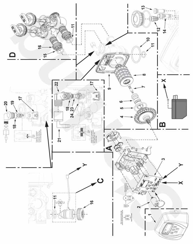
14 REPLACEMENT PARTS: 14
15 REPLACEMENT PARTS: Ref. PART NO. DESCRIPTION A CV3002CC Drive Assembly, IM Series B CV3186 Power Cord with Transformer, Clack Impression Valve C CV3003 Meter and Cable Assembly D CV3006 Bypass Valve, IM Series, less I/O fittings 1 CV3175CC-01GR Gray Front Cover, IM Series 2 CV Drive Motor, IM Series 3 CV3108CC Circuit Board, IM Series Valve 4 CV3004 Drive Cap Assembly 5 CV3135 O-ring, CV3011 Piston Assembly, IM Series 7 CV3174 Brine Valve, IM Series 8 CV3005 Seal Cartridge Assembly, IM Series 9 CV3178 Back plate for IM Series valve 10 CV3180 Base o-ring for IM Series valve, CV3105 O-ring, CV Injector screen, IM Series 13 CV3010-1Z Injector Assembly Plug 14 CV3010-1E Clack Injector, White (for 1.5 cubic feet and less) CV3010-1F Clack Injector, Dark Blue (for 2 cubic feet and higher) 15 CV3150 Split Ring Retainer 16 CV3151 Nut, 1" Quick Connect 17 CH4615 Elbow Locking Clip 18 CV3163 O-ring, CV Refill Flow Control Retainer 20 CH4613 Brine Fitting, 3/8" Tube 21 GL /4" Female NPT x 1/2" Barb Elbow 22 CV Drain Elbow 3/4" Male Assy 23 CV DLFC Retainer Assembly 24 Drain Line Flow Control Button: CV Flow Control Washer, 1.0 GPM (for IMI34) CV Flow Control Washer, 1.3 GPM (for INT34) CV Flow Control Washer, 1.7 GPM (for IM24 and IM30) CV Flow Control Washer, 2.2 GPM (for IMC24, IMC30, IM45, and IMI68) CV Flow Control Washer, 3.2 GPM (for IM60 and IM75 ) 15


16 INSTALLATION FITTING ASSEMBLIES: 1" PVC MALE NPT ELBOW 3/4" & 1" PVC SOLVENT ELBOW Item Part Item Part Description Qty No. No. No. No. Description Qty CV3007 1" PVC male NPT elbow assy. 2 CV /4" & 1" PVC solvent elbow assy. 2 1 CV3151 Nut, 1" quick connect 2 1 CV3151 Nut, 1" quick connect 2 2 CV3150 Split ring 2 2 CV3150 Split ring 2 3 CV3105 O-ring CV3105 O-ring CV3149 Fitting 2 4 CV3189 Fitting 2 1" BRASS SWEAT 3/4" BRASS SWEAT Item Part Item Part Description Qty No. No. No. No. Description CV " brass sweat assembly 2 CV /4" brass sweat assembly 2 1 CV3151 Nut, 1" quick connect 2 1 CV3151 Nut, 1" quick connect 2 2 CV3150 Split ring 2 2 CV3150 Split ring 2 3 CV3105 O-ring CV3105 O-ring CV3188 Fitting 2 4 CV Fitting 2 Qty 16

17 INSTALLATION FITTING ASSEMBLIES: /4" COPPER Q-TITE CONNECTOR Item Part No. No. Description Qty QT-34 KIT Fittings, Items # CV3105 O-ring CV3151 Nut, 1" quick connect 2 3 PEX-L PEX tubing insert 2 Loosens Drain Nut In Polytube Applications Loosens Injector and Bypass Caps SERVICE WRENCH - CV3193 Although no tools are necessary to assemble or disassemble the valve, the Service Wrench, (shown in various positions on the valve) is available to aid in assembly or disassembly. Loosens Quick Connect Nuts Loosens Drive Cap 17
18 SPECIFICATIONS: UNIT MODEL NUMBER 1 IMC24 IMC30 IM24 IM30 IM45 IM60 IM75 MEDIA VOLUME (ft 3 ) CAPACITY Salt Setting (6#/ft 3 ) 13,500 18,000 13,500 18,000 27,000 36,000 Salt Setting (9#/ft 3 ) 15,750 21,000 15,750 21,000 31,500 42,000 Salt Setting (15#/ft 3 ) 24,000 32,000 24,000 32,000 48,000 64,000 80,000 SERVICE FLOW RATES (gpm) Continuous Peak PRESSURE LOSS (psi) Continuous Flow Rate Peak Flow Rate REGENERATION FLOW RATES (gpm) Backwash Brine Draw and Slow Rinse Rapid Rinse FACTORY REGENERATION SETTINGS Brine Fill (# of salt) Softening (minutes) Backwash (minutes) Brine & Rinse (minutes) Rapid Rinse (minutes) Total Water Used (gallons) DIMENSIONS (in.) Mineral Tank (diameter x height) 10 x x 35 8 x 44 9 x x x x 54 Brine Tank (diameter x height) 11 x 11 x x 11 x x x x x x 33 Overall (length x width x height) 11 x 21 x x 21 x x 26 x x 27 x x 28 x x 30 x x 31 x 62 GENERAL REQUIREMENTS: Water Temperature 33 F F Water Pressure psi Electrical Requirements 110v/60hz Electrical Current Draw 0.5 amps Maximum Iron Concentration ppm Notes: Unit models listed include 3/4" Q-Tite plumbing connections. If 1" elbow connections are required use "-1" as suffix to the unit model number (i.e. IM30-1). Pressure loss information is approximate. Actual pressure loss may vary depending on water quality, temperature, gallons used since last regeneration, etc. Water softeners can be expected to remove reasonable amounts of clear water (ferrous) iron only. For best results an iron filter is recommended. Anytime red water (ferric) iron or iron bacteria is present an iron filter is required. 18
19 SPECIFICATIONS: MEDIA VOLUME (ft 3 ) UNIT MODEL NUMBER 1 INT34 IMI34 IMI CAPACITY Salt Setting (6#/ft 3 Salt Setting (9#/ft 3 Salt Setting (15#/ft 3 ) 18,000 18,000 36,000 21,000 21,000 42,000 34,000 34,000 68,000 SERVICE FLOW RATES (gpm) Continuous Peak PRESSURE LOSS (psi) Continuous Flow Peak Flow Rate REGENERATION FLOW RATES (gpm) Backwash Brine Draw and Slow Rinse Rapid Rinse FACTORY REGENERATION SETTINGS Brine Fill (# of salt) Softening (minutes) Backwash (minutes) Brine & Rinse (minutes) Rapid Rinse (minutes) Total Water Used (gallons) DIMENSIONS (in.) Mineral Tank (diameter x height) Brine Tank (diameter x height) Overall (length x width x height) 10 x 35 9 x x x 11 x x x x 22 x x 27 x x 30 x 56 GENERAL REQUIREMENTS: Water Temperature 33 F F Water Pressure psi Electrical Requirements 110v/60hz Electrical Current Draw 0.5 amps Maximum Iron Concentration ppm Notes: Unit models listed include 3/4" Q-Tite plumbing connections. If 1" elbow connections are required use "-1" as suffix to the unit model number (i.e. IM30-1). Pressure loss information is approximate. Actual pressure loss may vary depending on water quality, temperature, gallons used since last regeneration, etc. Water softeners can be expected to remove reasonable amounts of clear water (ferrous) iron only. For best results an iron filter is recommended. Anytime red water (ferric) iron or iron bacteria is present an iron filter is required. 19

, complete the following steps: For Immediate")
 TO SET TIME OF DAY In the event of a pro- 1. Accessed by longed power outage, pressing SET CLOCK time of day flashes, 2. Adjust hours with indicating that this and buttons, needs to be reset.")
20 QUICK REFERENCE GUIDE: GENERAL OPERATION When the system is operating, one of three displays will be shown: Time of day, gallons per minute, or gallons of treated water available. Pressing NEXT will toggle between the three choices. MANUAL REGENERATION CAPACITY REMAINING NOTE: For softeners, if brine tank does not contain salt, fill with salt and wait at least 1.5 hours before regeneration. If you need to initiate a manual regeneration, either immediately, or the same night at the preprogrammed time for regeneration (typically 2:00 AM), complete the following steps: For Immediate Regeneration: Press and hold REGEN until valve motor starts (typically 3 seconds). For Regeneration the same night: Press and release REGEN (notice that flashing "REGEN TODAY" appears.) TO SET TIME OF DAY In the event of a pro- 1. Accessed by longed power outage, pressing SET CLOCK time of day flashes, 2. Adjust hours with indicating that this and buttons, needs to be reset. All AM/PM toggles at 12 other information will 3. Press NEXT be stored in memory no 4. Adjust minutes with matter how long the and buttons power outage. Please 5. Press NEXT to complete the steps as complete and return to shown to the right. To normal operation. access this mode, press SET CLOCK ERROR If the display toggles between "Error" and an error code (i.e. a number), call a service technician and report the error code. BYPASS VALVE OPERATION To shut-off water to the system, please position arrow handles as shown in the bypass operation diagram below. If your valve doesn't look like the diagram below, contact your service technician for instructions on how to shut off water. NORMAL OPERATION BYPASS OPERATION "TREATED" WATER EXITS SUPPLY WATER ENTERS SUPPLY WATER EXITS SUPPLY WATER ENTERS ADJUST HARDNESS, DAYS BETWEEN REGENERATION, OR TIME OF REGENERATION For initial set-up or to 1. Accessed by pressing make adjustments, NEXT and button please complete simultaneously the steps as shown to 2. Adjust hardness setting the right. Access this and buttons mode by pressing 3. Press NEXT NEXT and button 4. Adjust days between simultaneously. regenerations using and buttons NOTE: Hardness display 5. Press NEXT shows "-na-" if used as 6. Adjust time of regena filter. If other displays eration hour with do not appear, refer to and buttons, AM/PM manual. toggles at Press NEXT 8. Adjust time of regeneration minutes with and buttons. 9. Press NEXT to complete and return to normal operation US Highway 33 North Churubusco, IN Phone: (260) Fax: (260)
21 TEN YEAR LIMITED WARRANTY WARRANTY First Sales, LLC warrants this water conditioner against any defects that are due to faulty material or workmanship during the warranty period. This warranty does not include damage to the product resulting from accident, neglect, misuse, misapplication, alteration, installation or operation contrary to printed instructions, or damage caused by freezing, fire, flood, or Acts of God. From the original date of consumer purchase, we will repair or replace, at our discretion, any part found to be defective within the warranty period described below. Purchaser is responsible for any shipping cost to our facility and any local labor charges. One year on the entire water conditioner Five years on the control valve Five years on the salt storage tank Ten years on the mineral tank GENERAL CONDITIONS Should a defect or malfunction occur, contact the dealer that you purchased the product from. If you are unable to contact the dealer, contact First Sales, LLC at (260) We will require a full description of the problem, model number, serial number, date of purchase, and selling dealer s business name and address. We assume no warranty liability in connection with this water conditioner other than specified herein. This warranty is in lieu of all other warranties, expressed or implied, including warranties of fitness for a particular purpose. We do not authorize any person or representative to assume for us any other obligations on the sale of this water conditioner. FILL IN AND KEEP FOR YOUR RECORDS Original Purchaser Date of Purchase Model # Serial # Address of Original Installation City State Dealer Purchased From Dealer Address City State First Sales, LLC U.S. 33 North, Churubusco, IN 46723
Installation Instructions and Owner s Manual. HE, IM & INT Series. Water Softener System
 Installation Instructions and Owner s Manual HE, IM & INT Series Water Softener System First Sales, LLC 1630 US Highway 33 N Churubusco, IN 4673 Phone (60) 693-197 Fax (60) 693-060 HE-IM-INT Instruction
Installation Instructions & Operating Manual. EM Series. Water Softener System
 Installation Instructions & Operating Manual EM Series Water Softener System First Sales, LLC 1630 US Highway 33 N Churubusco, IN 4673 Phone (60) 693-197 Fax (60) 693-060 EM Installation Manual 170818.docx
TITAN VI High Efficiency Water Conditioner Installation and Operation Manual
 TITAN VI High Efficiency Water Conditioner Installation and Operation Manual Manufacturer s Warranty Holts Water Conditioning 369 South Mountainway Drive Orem, UT 84058 801-426-9243 To the original purchaser,
TITAN Pro-Max High Efficiency Upflow Water Conditioner Installation and Operation Manual
 TITAN Pro-Max High Efficiency Upflow Water Conditioner Installation and Operation Manual TITAN VI Pro-Max Manufacturer s Warranty Holts Water Conditioning 369 South Mountainway Drive Orem, UT 84058 801-426-9243
Owner s Manual. Models: AWP-SE1 and AWP-SE2 Series Water Conditioners _RevG
 Owner s Manual Models: AWP-SE and AWP-SE Series Water Conditioners 5 Clair Rd. W, Guelph, Ontario, Canada NL R t. (+) 59.76.0 tf..800.65.76 (US and Canada only) t. + 7 77 0 (Europe only) f. (+) 59.76.5069
Installation Instructions and Owner s Manual. PDIM Series. Water Softener System
 Installation Instructions and Owner s Manual PDIM Series Water Softener System First Sales, LLC 1630 US Highway 33 N Churubusco, IN 4673 Phone (60) 693-197 Fax (60) 693-060 PDIM Instruction Manual 170717.docx
TotalCare, CareSoft Elite CareSoft Pro. and. Series. Water Softeners and Conditioners. For Models: TC1 TC2 CSE CSERC CSP CSPRC
 TotalCare, CareSoft Elite CareSoft Pro Series Water Softeners and Conditioners and For Models: TC TC2 CSE CSERC CSP CSPRC For Cabinet Models: CSEC CSPC TABLE OF CONTENTS Preinstallation Instructions for
Evolve Series. Water Softeners and Conditioners. For Models: EV1 EV2 EVR EVRC EVRS EVRCS. For Cabinet Models: EVC EVCS
 Evolve Series Water Softeners and Conditioners For Models: EV EV EVR EVRC EVRS EVRCS For Cabinet Models: EVC EVCS TABLE OF CONTENTS Pre-Installation Instructions for Dealers... Bypass Valve.... Installation....5
Owner's Manual. Whole House Water Softener with Triton Electronic Control Valve. or call
 Owner's Manual SoftMAX Whole House Water Softener with Triton Electronic Control Valve ACTIVATE YOUR WARRANTY BY REGISITERING YOUR PRODUCT AT WWW.WATERTECH.COM or call 888-254-8412 Dealer Contact and Product
Installation & Service Manual
 Installation & Service Manual Table of Contents Unpacking & Inspection... 2 Basic Guidelines... 2 Specifications... 3 Before Starting Installation Where to install the filter... 4 Tools, pipe, fittings
CMP & C METERED SERIES
 INSTALLATION, OPERATION, AND MAINTENANCE MANUAL CMP & C METERED SERIES RESIDENTIAL WATER CONDITIONER COMPLETE FOR FUTURE REFERENCE: MODEL NO: SERIAL NO: DATE INSTALLED: DEALER: Marlo Incorporated 2227
Installation Instructions and Owner s Manual. N, NMS, NES, & INT2 Series. Water Softening Systems
 Installation Instructions and Owner s Manual N, NMS, NES, & INT2 Series Water Softening Systems MODEL NUMBERS: Time Clock Mechanical Metered NC Series NMCS Series N Series NMS Series High Efficiency High
Installation Instructions and Owner s Manual. FSN Series. Nitrate Removal Water Softening System
 Installation Instructions and Owner s Manual FSN Series Nitrate Removal Water Softening System First Sales, LLC 12630 US Highway 33 N Churubusco, IN 46723 Phone (260) 693-1972 Fax (260) 693-0602 FSN Series
Installation Instructions and Owner s Manual. CITY Series Water Softening and Filter System
 Installation Instructions and Owner s Manual CITY Series Water Softening and Filter System First Sales, LLC 12630 US Highway 33 N Churubusco, IN 46723 Phone (260) 693-1972 Fax (260) 693-0602 CITY Series
Clean Water Made Easy
 Clean Water Made Easy http://www.cleanwaterstore.com Pro-OX 1650 Iron Filter Installation & Start-Up Guide Thank you for purchasing a Clean Water System! With proper installation and a little routine maintenance
WS1 Greensand Installation & Start Up Guide
 WS1 Greensand Installation & Start Up Guide Thank you for purchasing a WS1 Water System for the removal of iron, manganese and hydrogen sulphide gas. With proper installation and a little routine maintenance
WS1 Softener Installation & Start-Up Guide
 WS1 Softener Installation & Start-Up Guide Thank you for purchasing a Van Isle Conditioner. With proper installation and a little routine maintenance your system will be providing treated water for many
Owner s Manual. 12 Volt Electronics. AMERICAN AQUA Saline, MI (734) Howell, MI (517) Adrian, MI (517)
 Howell, MI (517) Adrian, MI (517)") 12 Volt Electronics Owner s Manual 2001-2009 AMERICAN AQUA Saline, MI (734)429-5070 Howell, MI (517)546-1750 Adrian, MI (517)265-8000 www.americanaqua.com This owner s manual is designed to assist owners
12 Volt Electronics Owner s Manual 2001-2009 AMERICAN AQUA Saline, MI (734)429-5070 Howell, MI (517)546-1750 Adrian, MI (517)265-8000 www.americanaqua.com This owner s manual is designed to assist owners
Installation Instructions and Owner s Manual. FS, FSM, & FES Series. Water Softening System
 Installation Instructions and Owner s Manual FS, FSM, & FES Series Water Softening System MODEL NUMBERS: Time Clock Mechanical Metered FSL Series FSLM Series FS Series FSM Series High Efficiency High Efficiency
5700-E Sediment Filter Installation & Start-Up Guide
 Clean Water Made Easy www.cleanwaterstore.com 5700-E Sediment Filter Installation & Start-Up Guide Thank you for purchasing a Clean Water System! With proper installation and a little routine maintenance
Clean Water Made Easy
 Clean Water Made Easy http://www.cleanwaterstore.com Pro-OX 5700-E Iron Filter Installation & Start-Up Guide Thank you for purchasing a Clean Water System! With proper installation and a little routine
AUTOTROL 363TC AUTOMATIC FILTER VALVE SERVICE MANUAL
 AUTOTROL 363TC AUTOMATIC FILTER VALVE SERVICE MANUAL 2013 Pentair Residential Filtration, LLC www.pentairaqua.com/pro TABLE OF CONTENTS MANUAL OVERVIEW... 2 SAFETY INFORMATION... 2 TYPICAL TOOLS AND FITTINGS
MP-MBA-45T-1/60T-1 / 75T-1
 MASTER Water Conditioning Corp. www.masterwater.com Installation and Operation Manual MP-MBA-45T-1/60T-1 / 75T-1 with the 268/762 Logix Control Valve July 2006 Table of Contents Page No. Topic Description
Autotrol Performa FA Valve
 Autotrol Performa FA Valve With 400 Series Control Water Conditioning Control System Dealer Installation, Operation, and Maintenance Manual Table of Contents Installation................................
E 3. Owner s Manual. Manufactured by: HELLENBRAND, INC. Phone: Fax Web:
 E 3 Owner s Manual Manufactured by: HELLENBRAND, INC. Phone: 608-849-3050 Fax 608-849-7398 Web: www.hellenbrand.com Email: info@hellenbrand.com 2011 This owner s manual is designed to assist owners and
Clean Water Made Easy. CWS Time Clock Softener Installation & Start Up Guide. Questions?
 Clean Water Made Easy www.cleanwaterstore.com CWS Time Clock Softener Installation & Start Up Guide Thank you for purchasing a Clean Water System! With proper installation and a little routine maintenance
7800 Neutralizer Installation & Start-Up Guide
 Clean Water Made Easy www.cleanwaterstore.com 7800 Neutralizer Installation & Start-Up Guide Thank you for purchasing a Clean Water System! With proper installation and a little routine maintenance your
Installation Instructions and Owner s Manual. XTS Series. Water Softening System
 Installation Instructions and Owner s Manual XTS Series Water Softening System First Sales, LLC 12630 US Highway 33 N Churubusco, IN 46723 Phone (260) 693-1972 Fax (260) 693-0602 XTS Series Instruction
OWNER S MANUAL. Premium Series Two Tank 1-PLUS-1 Water Conditioner & Whole House Filters
 OWNER S MANUAL Premium Series Two Tank 1-PLUS-1 Water Conditioner & Whole House Filters Congratulations! You ve selected our Premium Series Two Tank 1-PLUS-1 water conditioner and whole house filter for
Clean Water Made Easy
 Clean Water Made Easy http://www.cleanwaterstore.com Pro-OX 2510 Iron Filter Installation & Start- Up Guide Thank you for purchasing a Clean Water System! With proper installation and a little routine
Clean Water Made Easy. Fleck 7000 Tannin Filter Installation & Startup Guide. Questions?
 Clean Water Made Easy www.cleanwaterstore.com Fleck 7000 Tannin Filter Installation & Startup Guide For Tannin Filters with Vortech Distributor Screen Thank you for purchasing a Clean Water System! With
MASTER. Water Conditioning Corp. MP-TS-10T/20T with the 255/762 Logix Control Valve With Vortech. Installation and Operation Manual
 MASTER Water Conditioning Corp. www.masterwater.com Installation and Operation Manual MP-TS-10T/20T with the 255/762 Logix Control Valve With Vortech February 2010 Table of Contents Page No. Topic Description
Sanitizer Series. Water Conditioners
 Sanitizer Series Water Conditioners TABLE OF CONTENTS Installation Instructions..........................................3-4 Start-up Procedures.............................................5-6 Programming
Water Softener & Single Tank Triple Treat System Installation Overview. Using 1850 Metered Valves
 Water Softener & Single Tank Triple Treat System Installation Overview Using 1850 Metered Valves System Installation CAUTION: Do not use systems on untreated well water that is microbiologically unsafe.
1850 Series TRIPLE TREAT Operation Manual
 1850 Series TRIPLE TREAT Operation Manual BRINE TANK RESIN TANK CARBON TANK System shown with optional tank jackets. Note: 1. Read all instructions carefully before operation. 2. Avoid pinched o-rings
Fleck 5600 Carbon Filter Installation & Start Up Guide
 Clean Water Made Easy www.cleanwaterstore.com Fleck 5600 Carbon Filter Installation & Start Up Guide Thank you for purchasing a Clean Water System! With proper installation and a little routine maintenance
Installation Manual & Owner s Guide
 Installation Manual & Owner s Guide Table of Contents Benefits of Iron Shield +... 1 How Iron Shield + Works... 2 Unpacking & Inspection... 3 Basic Guidelines... 3 Specifications... 4 Regeneration Schedules...
CWS Plus Sediment Filter Installation & Start Up Guide
 Clean Water Made Easy www.cleanwaterstore.com CWS Plus Sediment Filter Installation & Start Up Guide Thank you for purchasing a Clean Water System! With proper installation and a little routine maintenance
SUPERIOR SOFT-TEC NO SALT WATER SOFTENER Installation & Operation Manual
 SUPERIOR SOFT-TEC NO SALT WATER SOFTENER Installation & Operation Manual Barrie, Ontario Canada L4N 4Y8 www.excaliburwater.com EXCALIBUR SUPERIOR SOFT-TEC NO SALT WATER SOFTENER INSTALLATION MANUAL In
Fleck 7000 Sediment Filter Installation & Start-Up Guide
 Clean Water Made Easy www.cleanwaterstore.com Fleck 7000 Sediment Filter Installation & Start-Up Guide Thank you for purchasing a Clean Water System! With proper installation and a little routine maintenance
AUTOTROL 363 DEMAND AUTOMATIC FILTER VALVE Service Manual
 AUTOTROL 363 DEMAND AUTOMATIC FILTER VALVE Service Manual 2014 Pentair Residential Filtration, LLC www.pentairaqua.com/pro TABLE OF CONTENTS MANUAL OVERVIEW... 2 SAFETY INFORMATION... 2 TYPICAL TOOLS AND
Clean Water Made Easy
 Clean Water Made Easy www.cleanwaterstore.com CWS Plus Neutralizer/Birm Blend Installation & Start-Up Guide Thank you for purchasing a Clean Water System! With proper installation and a little routine
Water Softener Installation Guide Effective for all Softeners from our Range
 Water Softener Installation Guide Effective for all Softeners from our Range Planning Your Installation Always observe the water byelaws. Ensure there is only one rising main, that you have allowed space
5900S Softener Installation & Start-Up Guide
 Clean Water Made Easy www.cleanwaterstore.com 5900S Softener Installation & Start-Up Guide Thank you for purchasing a Clean Water System! With proper installation and a little routine maintenance your
Fleck 2510 SXT Catalox Installation & Start Up Guide
 Fleck 2510 SXT Catalox Installation & Start Up Guide For Catalox Filters with PotPerm Bleach Solution Tank Thank you for purchasing a Clean Water System! With proper installation and a little routine maintenance
Installation Instructions and Owner s Manual. KLX2 & KLX2E Series. Catalytic Filter System
 Installation Instructions and Owner s Manual KLX2 & KLX2E Series Catalytic Filter System First Sales, LLC 12630 US Highway 33 N Churubusco, IN 46723 Phone (260) 693-1972 Fax (260) 693-0602 KLX2-KLX2E Instruction
Fleck 5600 SXT. Installation Guide. Make a list of all of the plumbing fittings needed to install; a typical list looks like this:
 Installation Guide Before you assemble your new system, be sure that the following conditions have been met for placement of your softener: Getting Started Level, firm surface, such as concrete, on which
ProMate EcoMax. Owner s Manual
 ProMate EcoMax Owner s Manual Manufactured by: HELLENBRAND, INC. 404 Moravian Valley Road Waunakee, Wisconsin 53597 Web: www.hellenbrand.com Email: info@hellenbrand.com 800663 Rev A. 12/30/15 2015 2 This
Installation, Operation and Maintenance Manual. Infusion Residential Water Softener 169-ISF-1C 169-ISF-2C 169-ISF-3C 169-ISF-4C
 Installation, Operation and Maintenance Manual Infusion Residential Water Softener Calcium, magnesium removal system 169-ISF-1C 169-ISF-2C 169-ISF-3C 169-ISF-4C US Water Systems, Inc. 1209 Country Club
Fleck 2510 Softener Installation & Start Up Guide
 Clean Water Made Easy www.cleanwaterstore.com Fleck 2510 Softener Installation & Start Up Guide Thank you for purchasing a Clean Water System! With proper installation and a little routine maintenance
5900S Arsenic Filter Operation & Maintenance Manual
 Clean Water Made Easy www.cleanwaterstore.com 5900S Arsenic Filter Operation & Maintenance Manual Thank you for purchasing a Clean Water System! With proper installation and a little routine maintenance
ProMate EcoMax. Consumer s Manual
 ProMate EcoMax Consumer s Manual Manufactured by: HELLENBRAND, INC. 404 Moravian Valley Road Waunakee, Wisconsin 53597 www.hellenbrand.com info@hellenbrand.com 112249 Rev D. 8/28/18 2016-2018 This owner
Consumer s Manual HELLENBRAND, INC.
 Consumer s Manual 2014 Manufactured by: HELLENBRAND, INC. 404 Moravian Valley Road Waunakee, Wisconsin 53597 Web: www.hellenbrand.com Email: info@hellenbrand.com This owner s manual is designed to assist
Green Water Systems OWNERS MANUAL. Includes: Installation Procedures, Warranties, Service & Operation Guidelines.
 Green Water Systems OWNERS MANUAL Includes: Installation Procedures, Warranties, Service & Operation Guidelines. GS Elite GS PRO GS1 1 Cu. Ft. S. C. S. GS1.5 1 Cu. Ft. S. C. S. GS2 2 Cu. Ft. S. C. S. 7000
Fully Automatic Water Softeners
 OWNERS GUIDE TO INSTALLATION AND OPERATION Fully Automatic Water Softeners SINGLE TANK CABINET MODELS TWO TANK MODELS Read the instructions carefully and learn the specific details regarding installation
Installation Instructions and Owner s Manual. O3 & O3E Series. Iron Reduction System
 Installation Instructions and Owner s Manual O3 & O3E Series Iron Reduction System First Sales, LLC 12630 US Highway 33 N Churubusco, IN 46723 Phone (260) 693-1972 Fax (260) 693-0602 O3-O3E Instruction
89 BIF/BAF USER MANUAL
 89 BIF/BAF USER MANUAL Owners Manual 1. Read all instructions carefully before operation. 2. Avoid pinched o-rings during installation by applying (provided with install kit) NSF certified lubricant to
Water Softener Installation / Operation Manual
 Water Softener Installation / Operation Manual BrassMaster and BrassMaster Plus Technical Video Library: http://watercontrolinc.com/residential-technical-support/residential-technical-videos BrassMaster
Installation Instructions and Owner s Manual. OXY3 & OXY3E Series. Iron Reduction System
 Installation Instructions and Owner s Manual OXY3 & OXY3E Series Iron Reduction System First Sales, LLC 12630 US Highway 33 N Churubusco, IN 46723 Phone (260) 693-1972 Fax (260) 693-0602 OXY3-OXY3E Instruction
Owner's Manual. WS Series. Water Softener
 Owner's Manual WS-165-150 Series Water Softener Table of Contents WHAT'S INCLUDED 3 OPERATING CONDITIONS 4 ASSEMBLY INSTRUCTIONS 6 FLUSHING THE WATER LINES 13 MASTERPROGRAMMING 14 PROGRAMMING KEYAND GENERAL
The Inlet and Outlet should be as per below illustration. This will ensure that water will flow through the filter in an upflow configuration
 Owners Manual The Inlet and Outlet should be as per below illustration. This will ensure that water will flow through the filter in an upflow configuration INLET OUTLET NRV Filter FOLLOWTHE INSTALLATION
AUTOTROL 360 MANUAL & 361 SEMI-AUTOMATIC FILTER VALVES SERVICE MANUAL
 AUTOTROL 360 MANUAL & 361 SEMI-AUTOMATIC FILTER VALVES SERVICE MANUAL waterpurification.pentair.com TABLE OF CONTENTS MANUAL OVERVIEW... 2 SAFETY INFORMATION... 2 TYPICAL TOOLS AND FITTINGS REQUIRED...
A3000 Series Water Softener
 A3000 Series Water Softener A3000 Series Water Softener Manual www.angelwater.com 21 S. Main St. Elburn, IL 60119 630.365.2600 214 S. Hager Ave. Barrington, IL 60010 847.382.7800 Welcome to the Angel Family!
Installation, Operation, and Maintenance Manual. Waterlogix Metered Residential Water Softener
 Installation, Operation, and Maintenance Manual Waterlogix Metered Residential Water Softener Waterlogix WLS-075 Waterlogix WLS-075C Waterlogix WLS-100 Waterlogix WLS-100C Waterlogix WLS-150 Waterlogix
GE & PROFILE SmartWater Softener Systems
 GE & PROFILE SmartWater Softener Systems INSTALLATION INSTRUCTIONS GE Models GNSF18Z01, GNSF2Z01, GNSF5Z01, GXSF2Z01 & Profile Model PNSF1Z01 TABLE OF CONTENTS: Page # Important Installation Recommendations
2.0 HIGH CAPACITY SIMPLEX WATER SOFTENER INSTALLATION AND OPERATIONS MANUAL
 2.0 HIGH CAPACITY SIMPLEX WATER SOFTENER INSTALLATION AND OPERATIONS MANUAL www.excaliburwater.com Barrie, ON L4N 4Y8 Water Softener Introduction: Please read Excalibur Water Systems Water Softener manual
Installation and Operations Manual
 Excalibur Water Systems 2.0 HIGH CAPACITY Mid Series SIMPLEX WATER SOFTENER Installation and Operations Manual 142 Commerce Park Drive, Units M-O, Barrie ON L4N 8W8 www.excaliburwater.com Water Softener
Autotrol Brand Performa Valve / 400 Series Controls
 Autotrol Brand Performa Valve / 400 Series Controls Water Conditioning Control System Home Owner Installation, Operation, and Maintenance Manual For sales or service questions please contact your local
High Performance System
 High Performance System Owner s Manual Manufactured by: HELLENBRAND, INC. 404 Moravian Valley Road Waunakee, Wisconsin 53597 Phone: 608-849-3050 Fax 608-849-7398 Web: www.hellenbrand.com Email: info@hellenbrand.com
NovoSoft 465 Series SIM Water Softener Operation Manual
 NovoSoft 465 Series SIM Water Softener Operation Manual Note: 1. Read all instructions carefully before operation. 2. Avoid pinched o-rings during installation by applying (provided with install kit) NSF
Autotrol Brand 255 Valve / 400 Series Controls
 Autotrol Brand 255 Valve / 400 Series Controls Water Conditioning Control System Home Owner Installation, Operation, and Maintenance Manual For sales or service questions please contact your local dealer:
565 TLC Softener & Tannins Reduction System
 565 TLC Softener & Tannins Reduction System Owners Manual 1. Read all instructions carefully before operation. 2. Avoid pinched o-rings during installation by applying (provided with install kit) NSF certified
RAINFRESH CGFE GREENSAND FILTERS FOR REMOVAL OF IRON, MANGANESE & HYDROGEN SULFIDE. Installation & operation instructions
 RAINFRESH CGFE GREENSAND FILTERS FOR REMOVAL OF IRON, MANGANESE & HYDROGEN SULFIDE Installation & operation instructions Thank you for purchasing one of our ENVIROGARD / Rainfresh Greensand Filter Systems.
5900e Neutralizer Installation & Start Up Guide
 Clean Water Made Easy www.cleanwaterstore.com 5900e Neutralizer Installation & Start Up Guide Thank you for purchasing a Clean Water System! With proper installation and a little routine maintenance your
5900-BT Softener Installation & Start-Up Guide
 Clean Water Made Easy www.cleanwaterstore.com 5900-BT Softener Installation & Start-Up Guide Thank you for purchasing a Clean Water System! With proper installation and a little routine maintenance your
FLECK 5600 WATER SOFTENER INSTALLATION
 FLECK 5600 WATER SOFTENER INSTALLATION Discount Water Softeners recommends using a licensed plumber to install your water softener. The following installation instructions are for use with the water softener
Record of System Specifications 2 Product Dimensions 3 Pre-Installation Checklist 4 System Installation 5-9 Installation Notice, Unit location,
 Record of System Specifications 2 Product Dimensions 3 Pre-Installation Checklist 4 System Installation 5-9 Installation Notice, Unit location, Plumbing Setup, Control Valve Installation Instructions 5
Owner s Manual HELLENBRAND, INC.
 Owner s Manual Manufactured by: HELLENBRAND, INC. 404 Moravian Valley Road Waunakee, Wisconsin 53597 Web: www.hellenbrand.com Email: info@hellenbrand.com p/n 800198 Rev. B Updated 10/24/17 2016-2017 This
7500-S Sediment Backwash Filter Guide
 Clean Water Made Easy. www.cleanwaterstore.com 7500-S Sediment Backwash Filter Guide Thank you for purchasing a Clean Water System! With proper installation and a little routine maintenance your system
Consumer s Manual HELLENBRAND, INC.
 Consumer s Manual Manufactured by: HELLENBRAND, INC. 404 Moravian Valley Road Waunakee, Wisconsin 53597 Web: www.hellenbrand.com Email: info@hellenbrand.com 800527 Rev D 8/28/18 LBRY 2014-2018 This owner
5900e Greensand Filter Installation & Start-Up Guide
 Clean Water Made Easy www.cleanwaterstore.com 5900e Greensand Filter Installation & Start-Up Guide Thank you for purchasing a Clean Water System! With proper installation and a little routine maintenance
Installation and Operation Manual
 Installation and Operation Manual NOTE: RISER / DISTRIBUTOR PIPE SHOULD BE CUT 1/2 BELOW THE TOP SURFACE OF THE TANK INSERT. MTS 95 System REVISION # 3 REVISION DATE SEPTEMBER 12, 2013 2 Table of Contents
6700 Valve Downflow. Automatic Water Softeners Operation Manual. Read all instructions carefully before operation. #51431 Rev.
 6700 Valve Downflow Automatic Water Softeners Operation Manual Read all instructions carefully before operation. #51431 Rev. 11/08 US Performance and Specifications Downflow Capacity at Various Salt Dosages
Fleck 2510 Sediment Filter Installation & Start-Up Guide
 Clean Water Made Easy www.cleanwaterstore.com Fleck 2510 Sediment Filter Installation & Start-Up Guide Thank you for purchasing a Clean Water System! With proper installation and a little routine maintenance
565 HIM Softener, Iron & Manganese Reduction System
 565 HIM Softener, Iron & Manganese Reduction System Owners Manual 1. Read all instructions carefully before operation. 2. Avoid pinched o-rings during installation by applying (provided with install kit)
FULLY AUTOMATIC WATER SOFTENER
 OWNERS GUIDE TO INSTALLATION AND OPERATION Section: 6.10.130 FM2035 0302 Supersedes 0102 FULLY AUTOMATIC WATER SOFTENER MODEL 340 SAFETY INFORMATION Read the instructions carefully and learn the specific
FUSION PROFESSIONAL-GRADE METERED NITRATE REMOVAL SYSTEM
 Visit us online at www.uswatersystems.com FUSION PROFESSIONAL-GRADE METERED NITRATE REMOVAL SYSTEM Owners Manual Models: 086-FNLT-XXX-NT REVISION # 1.0 REVISION DATE : September 18, 2018 US Water Systems
Model NFF Iron, Manganese, Hydrogen Sulfide Reduction
 Super Filter Model NFF Iron, Manganese, Hydrogen Sulfide Reduction Operating and Maintenance Manual Page 1 of this manual contains operating conditions. 57055 9/07 Enjoy clean, stain-free laundry and dishes...
High Flow 7000 SXT Water Softener
 High Flow 7000 SXT Water Softener Operating and Maintenance Manual WQA Tested and Certified against CSA B483.1 Read all instructions carefully before operation. #54736WQA 3/11 ii Performance Data Sheet
Birm 5900-BT Installation & Maintenance Guide
 Clean Water Made Easy www.cleanwaterstore.com Birm 5900-BT Installation & Maintenance Guide Thank you for purchasing a Clean Water System! With proper installation and a little routine maintenance your
Spectrum TM. Installation, Service & Operation Manual O FLO. SoftH 2. Water Softener. Table of Contents
 Installation, Service & Operation Manual SoftH 2 O FLO Water Softener Table of Contents 1. Description & Equipment Adjustments p.2 2. Components, Features & Functions p.3 3. Valve User Interface p.4 4.
6700 Valve Upflow. Automatic Water Softeners Operation Manual. Read all instructions carefully before operation. #57341 Rev.
 6700 Valve Upflow Automatic Water Softeners Operation Manual Read all instructions carefully before operation. #57341 Rev. 11/08 US Performance and Specifications Upflow Capacity at Various Salt Dosages
Econoflo SXT Automatic Meter Initiated Water Softener
 Econoflo SXT Automatic Meter Initiated Water Softener Operating and Maintenance Manual Page 5 of this manual contains important maintenance procedures for the continued proper operation of your unit. These
Fully Automatic Water Softeners
 OWNERS GUIDE TO INSTALLATION AND OPERATION Fully Automatic Water Softeners FW0782 0211 Supersedes 0410 Models S15DC29DR and S15DC39DR SAFETY INFORMATION Read the instructions carefully and learn the specific
HD / HDL Valves & Systems Service Manual
 Innovative Solutions for Your Water HD / HDL Valves & Systems Service Manual Hankscraft Runxin, LLC 300 Wengel Drive Reedsburg, WI 53959 608.524.9465 sales@hrh2o.com hrh2o.com 2 Table of Contents 1. Introduction...
Installation Instructions and Owner s Manual. XBW & XBW-ARSENIC Series. Backwashing Filter Systems
 Installation Instructions and Owner s Manual XBW & XBW-ARSENIC Series Backwashing Filter Systems First Sales, LLC 12630 US Highway 33 N, Churubusco, IN 46723 Phone (260) 693-1972 Fax (260) 693-0602 XBW
541D19 SERIES. Technical Manual. A Division of Aquion Partners L.P.
 541D19 SERIES Technical Manual A Division of Aquion Partners L.P. Table of Contents Introduction... Page 1 Technical Specifications... Page 2 Flow Diagrams... Page 3 Injector & Flow Control Selection Injector...
What to expect from your water softener
 What to expect from your water softener All water softeners work on the same basic principal. Hard water flows through a bed of resin and the calcium and magnesium, the minerals that are responsible for
7000 Meter Initiated Valve
 7000 Meter Initiated Valve Water Softener Operation Manual Read all instructions carefully before operation. #51400 Rev. 2/09 Performance and Specifications Item Model Capacity at regeneration salt levels
Model 7000SXT. Service Manual. IMPORTANT: Fill in Pertinent Information on Page 3 for Future Reference
 Model 7000SXT Service Manual IMPORTANT: Fill in Pertinent Information on Page 3 for Future Reference Table of Contents Job Specification Sheet... 3 Installation Instructions... 4 Start-Up Instructions...