Installation Guide & Owner s Manual. Water Source Heat Pumps Vertical / Horizontal 1 5 Nominal Ton GEOCOOL SERIES
|
|
|
- Stuart Ellis
- 6 years ago
- Views:
Transcription


1 Installation Guide & Owner s Manual Water Source Heat Pumps Vertical / Horizontal 1 5 Nominal Ton Rev GEOCOOL SERIES Reader should pay particular attention to the words: NOTE, CAUTION, and WARNING. NOTES are intended to clarify or make the installation easier. CAUTIONS are given to prevent equipment damage. WARNINGS are given to alert reader that personal injury and/or equipment damage may result if installation and/or service are not handled properly. 1
2 Table of Contents 1. Description General Feature Overview Safety 2. Installation General Codes and Ordinance Handling Location Service and Installation Clearance Mounting and Suspension Duct Work Sealing Supplementary Cooling / Heating Water Line Piping Condensate Piping Electrical Filters Enhanced Dehumidification Control Wiring Thermostat Wiring Diagram 3. Completion General Check out Start up Commissioning 4. Operation and Maintenance General Maintenance and Schedule Filters Blower Assembly Indoor Coil(s) Water Heat Exchanger Service 5. Troubleshooting 6. Appendix 1 Unit Configuration 7. Appendix 2 Model Number Nomenclature

3 The equipment is protected by a standard limited warranty under the condition that initial installation, service, start up and maintenance is performed according to their instru ction set forth in this manual. This manual should be read in its entirety prior to installation and before performing any service or maintenance work. Equipment description in this manual is available with various optional accessories. If you have questions after reading this manual in its entirety, consult other factory documentation or contact your sales representative to obtain further information before manipulating this equipment or its optional accessories. This unit must not be used at any time during any phase of construction. Very low return temperatures, harmful vapors and misplacement of the filters will damage the unit and its efficiency. 1. Description General GEOCOOL Heat Pumps are designed for high efficiency, durability, and easy service. Units are designed to minimize possible component damage if a problem occurs. In the cooling mode, heat is ejected from the heat pump into the source water loop. A cooling tower provides evaporative cooling to the loop water thus maintaining a constant temperature to the unit. When utilizing open cooling towers, chemical water treatment is mandatory to ensure the water is free from corrosive minerals. In the heating mode, heat is absorbed from the source water loop and puts into the refrigeration circuit through the heat exchanger. Important 1. For ground water applications (wells, lakes, etc.) entering water temperature should be no less than 50 0 F. 2. Water flow rate should match the rate specified for the unit. For Geothermal and other applications where water may reach freezing temperatures, sufficient anti freeze solution is to be used to avoid freezing of the heat exchanger and/or the water lines. Damage due to freezing is not covered under warranty. GEOCOOL source series single packaged unit consists of a high efficiency compressor, air to refrigerant evaporator coil, water to refrigerant condenser coil, expansion valve, reversing valve, centrifugal blower, high efficiency motor, a control panel with all necessary protection devices and safety circuit. Units are designed to operate with an entering water temperature between 50 0 F and F (suitable for a cooling tower/boiler application) but an extended range is available down to 25 0 F for Geo Thermo applications (for a Geothermal application sufficient anti freeze solution is to be used to avoid freezing of the heat exchanger and/or the water lines. 3


4 Feature Overview Centrifugal Blower Discharge Insulated Stainless Steel Cabinet Easy Slide out Filter Access FPT Water Connections Power and Controls Wire Inlets LED Lights Insulated Stainless Steel Drain Pan with FPT Connection Sample image is 1 ton Left Front water connections with Right return & Top supply 4

5 Safety WARNING! Installation and service must be performed by a qualified licensed installer or service agent. The information in this manual should be followed exactly to prevent damage or personal injury. Turn off electrical power to unit before servicing. Electric shock could cause personal injury or death. For your safety do not use gasoline or other flammable vapors and liquids in the vicinity of this unit or any other appliance. If the information in this manual is not followed exactly, a fire or explosion may result causing property damage, personal injury or loss of life. RISK OF DAMAGE, INJURY AND LOSS OF LIFE Improper installation, adjustment, alteration, service or maintenance can cause property damage, personal injury, or loss of life. A qualified installer or service agency must perform installation and service. RISK OF ELECTRICAL SHOCK Unit may have multiple power supplies. Turn the electrical power of the unit OFF and disconnect switch(es) before attempting to perform any service or maintenance. RISK OF INJURY FROM HOT PARTS Disconnect all power, close all isolation valves, and allow equipment to cool before servicing equipment with hot water or steam heating coils. Hot water will circulate even after power is off. Equipment may have multiple power supplies. RISK OF INJURY FROM MOVING PARTS Disconnect all power before servicing motor or blower to prevent serious injury resulting from automatic starts. Motor and blower may have multiple power supplies. Personal injury and/or equipment damage may result if installation and/or service are not handled properly. 5
6 . Installat on General GEOCOOL heat pumps are designed as a self contained heating, cooling or combination unit for indoor installation only. The use of flowing mediums shall be dictated by the specific design of the system and the unit. Flexible connectors are required on all duct connections to minimize air leaks. Closed loop and pond applications require specialized design knowledge. No attempt at these installations should be made unless the dealer has received specialized training. WARNING! Always wear hand and eye protection when handling, installing, servicing or maintaining equipment. Sharp or pointed edges, moving parts and flying debris may cause personal injury. Codes and Ordinances System should be sized in accordance with National Warm Air Heating and Air Conditioning Association Literature or the Guide of American Society of Heating, Refrigeration and Air Conditioning Engineers. The installation must conform with local building codes or in the absence of local codes with (United States) ANSI / UL 1995, (Canada) current, C.S.A. Standard C22.2, No. 236, Canadian Electrical Code Part I, and C.S.A. Standard B52 Mechanical Refrigeration Code and local Plumbing or Waste Water Codes. WARNING! It is the responsibility of the installing contractor to comply with codes, ordinances, local and municipal building laws and manufacturer s instructions. Personal injury and/or equipment damage may result if proper procedures are not followed. Dependent upon the optional accessories ordered this equipment may contain fragile components and delicate electronics. Although the unit is constructed of sturdy materials, it is advised to avoid impacts and handling methods that may damage internal apparatus and structure, or the exterior surfaces of the unit. Take care not to apply destructive force to coils, coil and drain stub outs, or other parts protruding beyond the extents of the unit casing. Always handle the unit by its exterior casing, and never by any of the protruding parts. Location It is recommended that the heat pump should be centrally located in relation to the distribution system. It is recommended that the unit is installed within the applicable area. However, in areas where temperatures may reach freezing point unit must not be exposed to ambient conditions. If not, unit may have a severe freeze damage which warranty does not cover. The unit must be installed level and care should be taken to prevent damage to the cabinet. Other installation provisions may be necessary according to the job specifications. Service and Installation Clearance Before setting unit into place, caution must be taken to provide clearance for unit panels/doors that must be accessible for periodic service. These areas contain the controls, safety devices, refrigerant or water piping, shutoff valves and filter access. GEOCOOL heat pumps require a minimum of 20 inches of service clearance on the access panel s side of the unit in order to ensure enough room for removal, replacement or service of coils and other components if necessary. Mounting and Suspension An auxiliary (emergency) drain pan is recommended for all applications where there is a risk of water damage to surrounding structure or furnishings. Refer to local codes. Handling Be aware of what is contained in the equipment.
7 Floor Mounted Make sure the unit is level and mounted on a field supplied platform and rubber pads with a minimum height to ensure proper fall on the condensate line. A slope of no less than 2% is recommended. Other installation provisions may be necessary according to job specifications. Suspended The GEOCOOL horizontal water source heat pump is equipped with steel hanging mounts for suspended installations. The unit should be lifted into position by supporting the unit with the skid used for shipping. Suspend the unit from its four corners with field supplied 3/8 allthread rods. Secure the rods into the holes in the steel hanging mounts and secure with nuts and lock washers. Duct Work For new installations duct work should be designed and installed using current ASHRAE procedures which take into consideration proper air flow, proper distribution, sound level considerations, efficiency, durability, safety, etc. For existing duct systems please make sure unit fits the duct system in the aspects of flow rate, pressure drop, insulation and sound level. Any air leaks in existing system should be found and repaired. Flexible connectors are important for connections of unit to metal ductwork to eliminate transfer of vibrations. Ductwork should be properly insulated to avoid energy loss and condensation during the cooling cycle. Sealing It is very important to keep outside air from infiltrating the unit cabinet. Seal all piping penetrations with Armaflex, Permagum, or other suitable sealant. Also seal around drain connections, electrical connections, and all other inlets where air may enter the cabinet. This is especially important when the unit is installed in an unconditioned area. Supplementary Cooling / Heating When heat is called for, unit shall switch to mechanical heating. Should the unit have hot water, or steam capabilities, it shall be activated according to controls. Unit with Hot Water Coil Water supply lines must be insulated, properly fastened, drained and supported according to the local code requirements. Unit with Steam Coils The unit MUST be installed high enough to allow for a minimum of one (1) foot condensate drop leg off of the steam coil (or as recommended by the steam trap manufacturer). Lines should be insulated with approved insulation and be properly fastened, sloped and supported according to local code requirements. Unit with Water Side Economizer Water supply lines must be insulated with closed cell type pipe insulation or insulation that includes a vapor barrier. Lines should be properly fastened, drained and supported according to local code barriers. Water Line Piping Connect water supply and return lines to water inlet and outlet. Flexible hose may be used for waterline to reduce vibration and improve unit serviceability. Make sure hoses and or pipes are suitable for water system pressure and sized for proper flow rate. Galvanized pipe or fittings are NOT recommended for use with the GEOCOOL heat pumps due to possible galvanic corrosion. All plumbing, both supply and discharge water lines must be sized to handle water flow with a proper pressure drop. Pipe will sweat if low temperature water runs through the supply and discharge lines. These lines should be insulated to prevent damage from condensation. Solenoid valves if used should be a slow closing diaphragm type. If not, water hammer may occur on unit start up and shut down. Placing the solenoid valve on the outlet side of the system helps in the mitigation of this situation. 7
8 Caution: Inadequate water flow to heat exchanger due to improper pipes, valves or pump is dangerous to heat pump and constitutes abuse that will void the warranty of the compressor and/or heat exchanger. An in line water screen strainer is always recommended but it is imperative where poor water quality may exist. Ball valves with hose connections are recommended for back flushing and chemical cleaning of the evaporator condenser. Condensate Piping A drain trap must be connected to the drain pan at the unit. A condensate connection is provided on each side of the unit. Condensate piping should be installed according to local codes. The line should be one size larger than pipe size as the drain nipple and should pitch downward toward the building drain. Electrical WARNING! All electrical installations need to be performed by a licensed electrician and according to all applicable codes. Check the unit data plate to make sure it matches with the power supply. Proper fuses or HACR circuit breakers should be installed. See unit s nameplate for minimum amps and maximum fuse/breaker. Connect power to the unit according to the wiring diagram provided with the unit. Use ONLY copper wires for power lines. Do not over tighten the connections. The connection to the unit needs to be hand tightened. Connect drain line to the unit with a P trap to avoid pulling air from outside th e unit back through the drain line. The line should be insulated where the ambient conditions may cause a condensation on the surface of the pipe. An additional drain pan may be installed under the unit, and should include a separate drain line for overflow from the primary drain. An air break should be used with long runs of condensate lines. Drain pans in any air conditioning equipment, even when they have a built in slope to the drain, will have moisture present and will require periodic cleaning to prevent any build up of algae or bacteria. Cleaning of the drain pans will also prevent any possible plugging of the drain lines, and overflow of the pan itself. Some means to clean out the P trap should be provided. Only qualified personnel should clean drain pans, drain lines or the insides of equipment. The power and control wiring may be brought into unit through the holes provided on the unit s cabinet. Protect the branch circuit in accordance with code requirements. GEOCOOL control wires should not run with any other wires inside same conduit. The units must be electrically grounded in accordance with all applicable codes. Power can be applied to the unit after the control wiring is connected, and start up checks are complete. Filters Slide the correct filter in with arrow pointing towards the blower in the direction of airflow. Make sure filter(s) cover the entire coil(s). 8
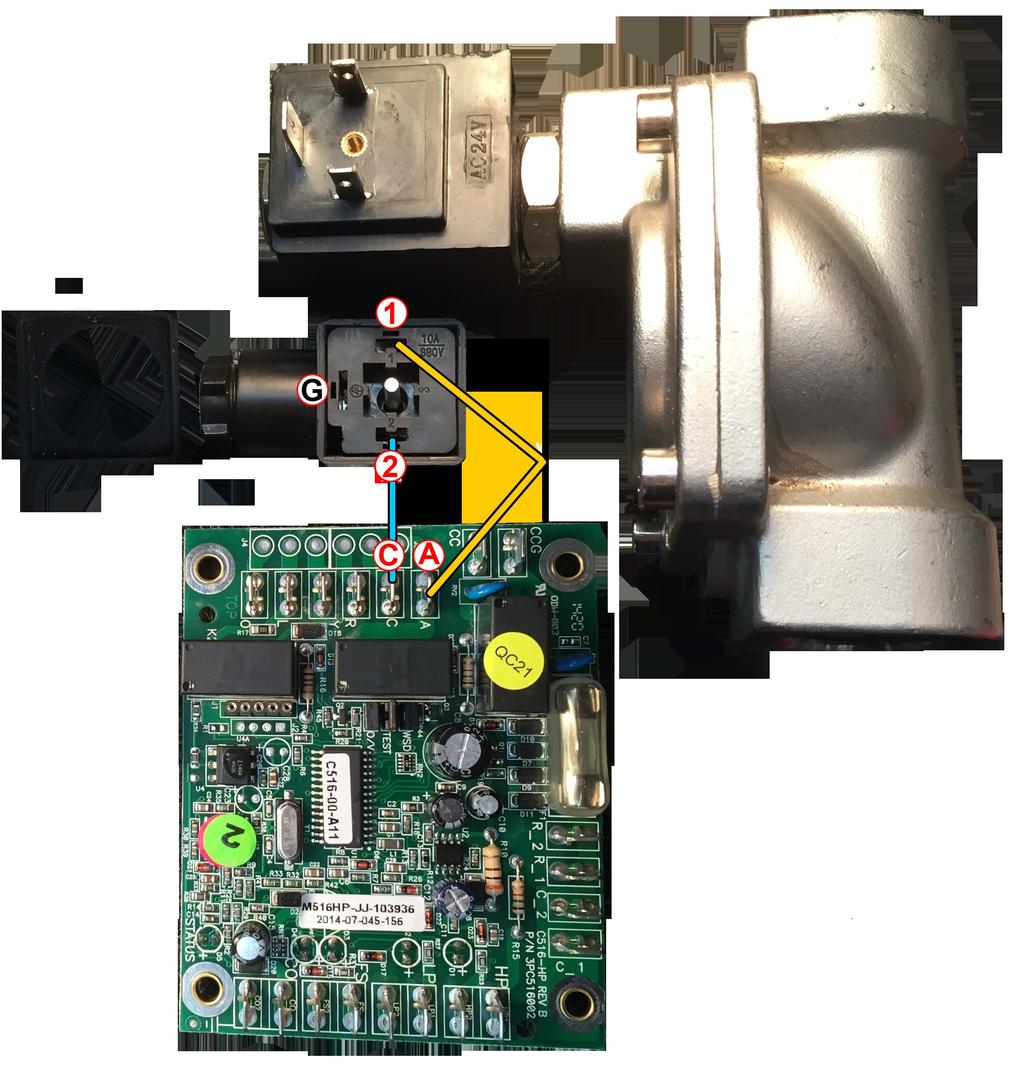
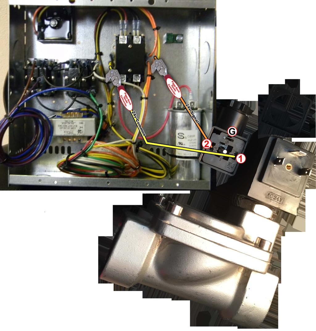
. If enhanced dehumidification is not required, the BLACK wire can be capped off and not used.")
9 Enhanced Dehumidification This function allows for reduced fan volume in order to increase dehumidification anytime the compressor is operating and the humidistat calls for dehumidification. The BLACK control wire requires a close on humidity rise humidistat (NO contacts). If enhanced dehumidification is not required, the BLACK wire can be capped off and not used. Thermostat Wiring Diagram This is an illustration of how most universal thermostats with dehumidification controls will be installed in your GEOCOOL heat pump system. Control Wiring GeoCool Unit Thermostat Terminals Red (24V Supply) Yellow (Compressor) Green (Fan Relay) White/Gray (Reversing Valve) Blue (24V Common) R Y G O C Black (Dehumidification) D or DH 9
10 Wiring Diagram Vertical Unit Wiring Diagram Horizontal Unit 10
11
12
13 . Start up Equipment operation during construction is not recommended. Construction site pollution may seriously degrade performance, damage unit and void all manufacturer warranties. Power should be on at least 24 hours prior to start up to allow crankcase heater(s) to boil off refrigerant that may have accumulated in the compressor(s) oil. Failure to adhere to the following start up procedures will void all manufacturer warranties. General Do not alter factory wiring. Deviation from the supplied wiring diagram shall void all warranties and may result in equipment damage and/or personal injury. Contact the factory with wiring discrepancies. ONLY QUALIFIED, AUTHORIZED PERSONNEL SHOULD POW ER ON, OR START UP THIS EQUIPMENT. The use of common sense, and good practice in the installation, and start up of equipment will prevent many potential problems with the system in the future. Before starting up the equipment, building construction should be complete, and start up personnel should: Have a working knowledge of general HVAC and mechanical commissioning procedures and practices. Be familiar with units functions, features, optional unit accessories, and all control sequences; Have appropriate literature on hand for consultation. Before the structure is occupied, the installation, start up personnel must take three essential steps: 1. Check Out 2. Start up 3. Commissioning Check Out Equipment should be thoroughly checked for loose wiring, a free spinning blower wheel, and wheel fitting access panels. Air handlers should not be operated without proper ductwork and access panels installed, except as required during start up and air balancing. 1. Check all electrical connections to be sure they are tight. 2. Open all access panels, and remove all shipping screws, or restraints. 3. Clean out any debris that may have been left. 4. Check belt alignment if any, and tightness of fan drives. 5. Check bearing locking collars, and fan wheel set screws for tightness. 6. Turn fan wheels to assure free rotation. 7. Ensure electrical supply matches the unit nameplate. 8. Ensure the existence of a drainage P trap. 9. Ensure condensate lines are connected, glued and have the right slope. 10. Check local codes for any special provisions. 11. Replace, and/or close all access panels. 12. Ensure that return, and/or supply dampers in ductwork are open. Start up Install gauges, voltmeter and amp meter before start up. Observe refrigerant pressures during initial operation. Note and determine the cause of any excessive sound, or vibration. Follow start up procedures outlined below to start each piece of equipment. 1. Make sure thermostat is OFF, turn the unit power ON. In three (3) phase unit check electrical phasing to ensure phase monitor turns on (where available) and fan rotates in proper direction. Switch phases if necessary. 2. Check and record water temperature, water flow rate, space temperatures and make sure all figures match the range of operation. 3. For GEOCOOL units please refer to Control Spec for GEOCOOL unit. 4. Set thermostat to highest temperature setting, turn fan switch to AUTO and mode of operation to COOL. 13
14 5. Make sure reversing valve is energized but neither fan nor compressor is running. 6. Reduce temperature setting to about five (5) degrees below room temperature. Fan should start immediately and compressor shall start after about three (3) minutes. In a unit with two (2) circuits second compressor shall start about three (3) minutes after first one has started. 7. Verify unit is cooling. 8. Turn system mode to HEAT and then set temperature to about five (5) degrees above room temperature. Compressor shall stop and then start after about three (3) minutes. In a unit with two (2) circuits second compressor shall start about three (3) minutes after the first one has started. 9. Verify unit is heating. 10. Set the thermostat to the desired temperature. 11. Instruct customer on the unit, the thermostat operation and the required maintenance. 12. Record all pressures, flow rates and temperatures related to operation. Optional Equipment / Accessory Any optional equipment and/or accessory which may come with the unit must be checked according to its specifications. Commissioning The commissioning of an air conditioning system is the process of achieving, verifying and documenting the performance of that system to meet the operational needs of the building. This may not be the formal process in smaller structures, such as a normal residence, but some form of owner acceptance will occur. Adjustments made during the commissioning phase may include air or water balancing or configuration of controls and operational sequences. Air Balancing The correct air balancing is imperative to achieve optimal comfort and efficiency of the entire system. Unqualified personnel should not attempt to adjust air circulation, as all systems have unique operating characteristics. Professional air balance specialists should be employed to establish actual operating conditions and to configure the air delivery system for optimal performance. Water Balancing When unit is one of many at the same water system, a specialist with a complete working knowledge of water systems, controls and operation must be employed to properly balance the entire system. Unqualified personnel should not attempt to manipulate temperatures, pressures or flow rates, as all systems have unique operating characteristics and improper balancing can result in undesirable noises and operation. Operation and Maintenance General A heat pump is a self contained system that requires professsional maintenance and repair. Other than replacing filters and keeping the exterior and surrounding areas of the unit clean, the homeowner should not attempt to make any adjustments or repairs to the heat pump system. A qualified licensed technician will be able to take care of any questions or problems which may occur. For either maintenance routine or in the event the unit is not functioning correctly a service company is required. Only a company with service technicians qualified and experienced in both heating and air conditioning should be permitted to service the systems in order to keep warranties in effect. The service tech may call the factory if assistance is required. After start up the air conditioning system requires a maintenance schedule. A maintenance program similar to the example given below should be scheduled for routine maintenance of this equipment in order to provide continued efficient and reliable operation for the owner. Maintenance Schedule Monthly: Check cleanliness of filters and replace if necessary. 14


15 Inspect coils, clean if dirty or obstructed in any way. In case of excessive noise or unusual operation check for reason and act accordingly. Quarterly: Check cooling coil drain pan and accessible condensate pipes and P trap to assure proper drainage. Clean if necessary. Check operation of heating and cooling section if seasonal. Check the inlet and outlet air temperatures. Determine cause for abnormal changes and act accordingly. Check water pressure drop to determine water flow, in case flow rate is out of range adjust water flow with unit s valves. Annually: Inspect and clean unit interior as necessary at the beginning of cooling season mode. Clean the drain line, P trap, and condensate pan. Clean evaporator coil. Clean the water to refrigerant heat exchanger. Check refrigerant pressures and temperatures every spring and correct unusual operation accordingly. Filters When the heat pump circulates and filters the air in your house, dust and dirt particles build up on the filter. Excessive accumulation can block the airflow, forcing the unit to work harder to maintain desired temperatures, thus costing more. Check filter at least once a month and change as needed with the same size filter. Filters on GEOCOOL heat pump units are easy to change as they slide out of side of unit easily. Replace old filters with the size indicated on each filter or as shown in the specific unit data. Be sure arrows on filter frames point toward the unit. Blower Assembly GEOCOOL heat pumps use forward curved blower wheels that are non overloading, very efficient and very easy clean. Clean blower wheels are necessary to reduce electrical use, maintain capacity and reduce stress on the unit. The blower wheel and blower section need to be inspected periodically, and cleaned of dust and debris. To inspect and clean the blower, set thermostat to OFF position turn the electrical power to the unit to OFF position at the disconnect switch. Clean the assembly, check for looseness, check screws for tightness, rotate blower wheel while listening close for noise or roughness. Indoor Coils Coils should be inspected and cleaned annually to ensure there is no obstruction to airflow. Dirty evaporator coils will eventually freeze up, and often result in time consuming and expensive service call. Clean filters will help to prevent dirt from accumulating on the evaporator; however the evaporator should be cleaned annually with a soft bristled brush and steam or a non corrosive coil cleaning solution. Move the brush in the fin direction. Make sure coil fins are not flattened. Water Heat Exchanger The efficiency of the unit is dependent on the water to refrigerant heat exchanger s performance. Therefore, a clean heat exchanger and a correct flow rate are imperative for minimizing the cost of operation. In severe cases dirty heat exchanger or flow rate out of range may cause the unit to malfunction. Heat exchanger can be cleaned by back flushing with or without the appropriate chemical available at a refrigeration supply shop. To obtain the correct flow rate adjust the water line valves. Service NOTE Phone: Fax: It is important to keep filters, water heat exchanger, coil and blower(s) clean. Be sure to have the model and serial number of the unit available when calling the warranty service department. These model and serial numbers will help them answer questions regarding your unit. 15
16 5. Troubleshooting Problems, Causes & Solutions For GEOCOOL unit please refer to Control Spec. for GEOCOOL unit and/or consult factory Problem Possible Cause Checks and Corrections Entire unit does not run Blower operates but compressor does not Unit OFF on high pressure switch Unit OFF on low pressure switch Unit Short Cycle Insufficient Cooling or Heating Power Supply OFF Blown Fuse Voltage Supply Low Thermostat Thermostat Wiring Capacitor Safety Controls Compressor Overload Open Compressor Motor Grounded Compressor Windings Open Discharge Pressure too High Refrigeration Charge High Pressure Suction Pressure too Low Refrigerant Charge Low Pressure Switch Unit Oversized Thermostat Wiring and Controls Unit Undersized Loss of Conditioned Air by Leaks Airflow Refrigerant Charge Compressor Reversing Valve Operating Pressures TXV/Capillary Tubes Moisture, Non condensable Apply power, close disconnect switch. Replace fuse or reset circuit breaker. Check for correct fuses. Contact local power company. Set the fan to ON, the fan should run. Set thermostat to COOL and lowest temperature setting. The unit should run in the cooling mode (reversing valve energized). Set unit to HEAT and the highest temperature setting. The unit should run in the heating mode. If neither the blower nor compressor runs in all three cases, the thermostat can be miswired or faulty. To ensure miswired or faulty thermostat verify 24 volts is available on condensing section low voltage terminal strip between R and C, Y and C and O and C if the blower does not operate. Verify 24 volts between terminals G and C in air handler. Replace thermostat if defected. Check setting, calibration and wiring. Check for loose or broken wire at compressor, or contactor. Check compressor capacitor if applicable. Check lock out relay for fault signal. If the compressor is cool and the overload will not reset, replace compressor. Internal winding grounded to the compressor shell. Replace compressor. If compressor burnout, install suction filter dryer. After compressor has cooled, check continuity of the compressor windings. If the windings are open, replace the compressor. In COOLING mode: lack of or inadequate water flow. Entering water temperature too warm scaled or plugged condenser. In HEATING mode: lack of or inadequate air flow. Blower inoperative clogged filter or restrictions in ductwork. The unit is overcharged with refrigerant. Reclaim refrigerant, evacuate and recharge with factory recommended charge. Check defective or improperly calibrated high pressure switch. In COOLING mode: lack of or inadequate air flow. Entering air temperature too cold. Blower inoperative clogged filter or restriction in ductwork. In HEATING mode: lack of or inadequate water flow. Entering water temperature too cold. Scaled or plugged condenser. The unit is low on refrigerant. Check for refrigerant leak, repair, evaluate and recharge with factory recommended charge. Check for defected or improperly calibrated low pressure switch. Recalculate cooling and/or heating loads. Thermostat installed near a supply air grill, relocate thermostat. Readjust heat anticipator. Loose connections in a wiring or defective compressor contactor. Recalculate heating and/or cooling loads. If excessive, possibly adding insulation and shading will rectify the problem. Check for leaks in ductwork or introduction of ambient air through doors or windows. Lack of adequate airflow or improper distribution of air. Replace dirty filter. Low refrigerant charge causing inefficient operation. Check for defective compressor. If discharge is too low and suction pressure is too high. Compressor is not pumping properly. Replace compressor. Defective reversing valve creating bypass of refrigerant from discharged to suction side of compressor. Replace reversing valve. Compare unit operating pressures to pressure / temperature chart of the unit. Check for possible restriction or defect. Replace if necessary. The refrigeration system may be contaminated with moisture or non condensable. Reclaim refrigerant, evacuate and recharge with factory recommended charge. Note: a liquid line dryer may be required. 16
RV Products Division INSTALLATION INSTRUCTIONS FOR SERIES PACKAGE AIR CONDITIONER
 RV Products Division INSTALLATION INSTRUCTIONS FOR 46413 SERIES PACKAGE AIR CONDITIONER 1. WARNINGS IMPORTANT NOTICE These instructions are for the use of qualified individuals specially trained and experienced
WMHP Series R410a Heat Pump INSTALLATION INSTRUCTIONS
 WMHP Series R410a Heat Pump INSTALLATION INSTRUCTIONS **WARNING TO INSTALLER, SERVICE PERSONNEL AND OWNER** Altering the product or replacing parts with non authorized factory parts voids all warranty
CROWN. Boiler Co. Santa-Fe Series. Hydronic Air Handlers INSTALLATION, OPERATION & MAINTENANCE INSTRUCTIONS
 CROWN Boiler Co Santa-Fe Series Hydronic Air Handlers INSTALLATION, OPERATION & MAINTENANCE INSTRUCTIONS These instructions must be affixed on or adjacent to the air handler Models: SAC049A20 SAC059A25
Fig. 1 - Unit PHD4 and WPH4
 OWNER S MANUAL 14 SEER Single -Package Heat Pump System with R -410A Refrigerant Single Phase and Three Phase 2 to 5 Nominal Tons PHD4 Series F and WPH4 Series B Fig. 1 - Unit PHD4 and WPH4 A09034 NOTE
Packaged Heat Pumps. Owner s Guide to Operating and Maintaining Your Heat Pump
 Packaged Heat Pumps Owner s Guide to Operating and Maintaining Your Heat Pump NOTE TO EQUIPMENT OWNER: For your convenience, please record the model and serial numbers of your new equipment in the spaces
Owner s Information Manual
 50EZ---A and 50VT ---A Comfort and Performance 13 and 14 SEER Single Packaged Heat Pump System With PuronR (R ---410A) Refrigerant Single and Three Phase 2---5 Nominal Tons (Sizes 24---60) Owner s Information
Fig. 1 - Unit PGD4, PGS4, WPG4
 OWNER S MANUAL 14 SEER Single -Package Air Conditioner and Gas Furnace System with R -410A Refrigerant Single Phase 2 to 5 Nominal Tons Three Phase 3 to 5 Nominal Tons PGD4andPGS4SeriesE,WPG4SeriesB Fig.
USER'S MANUAL PGE Single Package Rooftop
 USER'S MANUAL PGE Single Package Rooftop Gas Heating/Electric Cooling Units Sizes 036-150 3 to 12-1/2 Tons NOTE TO INSTALLER: This manual should be left with the equipment owner. WARNING: If the information
Packaged Gas/Electric Units. Owner s Guide to Operating and Maintaining Your Gas/Electric Unit
 Packaged Gas/Electric Units Owner s Guide to Operating and Maintaining Your Gas/Electric Unit ELECTRICAL SHOCK HAZARD. FIRE OR EXPLOSION HAZARD Disconnect power at fuse box or service panel before performing
Owner s Information Manual
 48ES---A and 48VL---A Comfort and Performance 13 and 14 SEER Single Packaged Air Conditioner and Gas Furnace System With Puron (R---410A) Refrigerant Single and Three Phase 2---5 Nominal Tons (Sizes 24---60)
UNDERCOUNTER LABORATORY REFRIGERATORS and FREEZERS Installation, Operation and Maintenance Instructions
 UNDERCOUNTER LABORATORY REFRIGERATORS and FREEZERS Installation, Operation and Maintenance Instructions INSPECTION When the equipment is received, all items should be carefully checked against the bill
Standard and CELDEK Evaporative Cooler Modules Installation, Operation, and Maintenance Manual
 Standard and CELDEK Evaporative Cooler Modules Installation, Operation, and Maintenance Manual Standard Evaporative Cooler CELDEK Evaporative Cooler RECEIVING AND INSPECTION Upon receiving unit, check
User s Information and Installation Instructions
 Outdoor Air Conditioner User s Information and Installation Instructions 10 SEER Standard Efficiency Split System These units have been designed and tested for capacity and efficiency in accordance with
User s Information and Installation Instructions
 Outdoor Air Conditioner User s Information and Installation Instructions 13 SEER R-410A High Efficiency Split System These units have been designed and tested for capacity & efficiency in accordance with
EC SERIES MODEL NOMENCLATURE
 EC SERIES Table of Contents Model Nomenclature...1 Introduction...2 Initial Inspection...2 General Description...2 Moving and Storage...2 Safety Considerations...2 Location...2 Installation...2 Condensate
EBAC MODEL WM150 INDUSTRIAL DEHUMIDIFIER OWNER S MANUAL
 EBAC MODEL WM150 INDUSTRIAL DEHUMIDIFIER OWNER S MANUAL WM150 OWNERS MANUAL Page 1 of 9 INTRODUCTION Designed for a wide range of applications, the WM150 is a rugged, industrial unit, which utilizes an
Standard and CELDEK Evaporative Cooler Modules Installation, Operation, and Maintenance Manual
 Standard and CELDEK Evaporative Cooler Modules Installation, Operation, and Maintenance Manual Standard Evaporative Cooler CELDEK Evaporative Cooler RECEIVING AND INSPECTION Upon receiving unit, check
Installation Guide. Dehumidification. Fresh Air Ventilation. Compact Size. Energy Efficient. RXID-AW90A Whole House Dehumidifier
 RXID-AW90A Whole House Dehumidifier with fresh air ventilation Installation Guide Dehumidification Fresh Air Ventilation Compact Size Energy Efficient The whole house dehumidifier integrates highcapacity
SPX SERIES PACKAGED AIR CONDITIONING/HEAT PUMP UNITS INSTALLATION, OPERATION AND MAINTENANCE INSTRUCTIONS
 SPX SERIES PACKAGED AIR CONDITIONING/HEAT PUMP UNITS INSTALLATION, OPERATION AND MAINTENANCE INSTRUCTIONS **WARNING TO INSTALLER, SERVICE PERSONNEL AND OWNER** Altering the product or replacing parts with
INSTALLATION INSTRUCTIONS Cased N Coil, Horizontal ENH4X
 INSTALLATION INSTRUCTIONS Cased N Coil, Horizontal ENH4X NOTE: Read the entire instruction manual before starting the installation. TABLE OF CONTENTS PAGE SAFETY CONSIDERATIONS... 1 INTRODUCTION... 1 INSTALLATION...
WineZone Ceiling Mount Ductless Split 15
 WineZone Ceiling Mount Ductless Split 15 Requires an HVAC technician to install and charge with R-22 refrigerant. Easy to install. Unit plugs into wall outlet. Industrial grade unit for longer life. Indoor
USERS INFORMATION MANUAL
 MODULAR DX OR CHILLED WATER COOLING WITH ELECTRIC OR HOT WATER HEATING MODELS: US, UM SERIES USERS INFORMATION MANUAL For Installation In: 1. Modular Homes & Buildings 2. Residential Homes LIST OF SECTIONS
User s Information and Installation Instructions
 Outdoor Air Conditioner User s Information and Installation Instructions 2-Stage R-410A Split System These units have been designed and tested for capacity & efficiency in accordance with A.H.R.I. Standards.
USER S INFORMATION MANUAL
 2017 Lennox Industries Inc. Dallas, Texas, USA 506737-01 04/2017 Supersedes 03/2017 USER S INFORMATION MANUAL EL195UHE SERIES GAS FURNACE Improper installation, adjustment, alteration, service or maintenance
INSTALLATION & OPERATING INSTRUCTIONS FOR CEILING MOUNT AIR HANDLERS AC SERIES
 C US INSTALLATION & OPERATING INSTRUCTIONS FOR CEILING MOUNT AIR HANDLERS AC SERIES Made in the USA by: Goodman Manufacturing Company, L.P. I0-240B 2550 North Loop West, Suite 400, Houston, TX 77092 www.goodmanmfg.com
CELDEK Evaporative Cooler Module Installation, Operation, and Maintenance Manual. CELDEK Evaporative Cooler
 CELDEK Evaporative Cooler Module Installation, Operation, and Maintenance Manual CELDEK Evaporative Cooler RECEIVING AND INSPECTION Upon receiving unit, check for any interior and exterior damage, and
F1 Series. Installation, Operation & Maintenance. Indoor Air Handing Units WARNING WARNING WARNING NOTICE QUALIFIED INSTALLER
 F1 Series Indoor Air Handing Units Installation, Operation & Maintenance WARNING QUALIFIED INSTALLER Improper installation, adjustment, alteration, service or maintenance can cause property damage, personal
INSTALLATION INSTRUCTIONS Cased N Coil, Horizontal ENH4X
 INSTALLATION INSTRUCTIONS Cased N Coil, Horizontal ENH4X NOTE: Read the entire instruction manual before starting the installation. TABLE OF CONTENTS PAGE SAFETY CONSIDERATIONS... 1 INTRODUCTION... 1 INSTALLATION...
INSTALLATION INSTRUCTIONS FMB/FMC SERIES MULTI-POSITION AIR HANDLER
 ASPEN MANUFACTURING 373 ATASCOCITA RD. HUMBLE, TX 77396 TEL (281) 441-6500 FAX (281) 441-6510 > INSTALLATION INSTRUCTIONS FMB/FMC SERIES MULTI-POSITION AIR HANDLER IMPORTANT: "The
Packaged Air Conditioning Units. Owner s Guide to Operating and Maintaining Your Air Conditioner. This manual should be left with the owner.
 Packaged Air Conditioning Units Owner s Guide to Operating and Maintaining Your Air Conditioner ELECTRICAL SHOCK HAZARD. Failure to follow this warning could result in personal injury, Disconnect power
INSTALLATION INSTRUCTIONS FMB/FMC SERIES MULTI-POSITION AIR HANDLER
 INSTALLATION INSTRUCTIONS FMB/FMC SERIES MULTI-POSITION AIR HANDLER IMPORTANT MASSAGE TO INSTALLER: "The United States Environmental Protection Agency ("EPA") has issued various regulations regarding the
INSTALLATION INSTRUCTIONS Cased N Coil, Horizontal ENH4X
 INSTALLATION INSTRUCTIONS Cased N, Horizontal ENH4X NOTE: Read the entire instruction manual before starting the installation. SAFETY CONSIDERATIONS Improper installation, adjustment, alteration, service,
Installation, Operating & Maintenance Instructions. Air Handler Models: AH & AV
 Installation, Operating & Maintenance Instructions Air Handler Models: AH & AV Table of Contents Table of Contents... 2 Product Safety... 2 Important Information About Safety Instructions... 2 Receiving...
Owner's Guide to Operating and Maintaining Your Gas/Electric Unit
 Packaged Gas Heat/Electric Cooling Units Owner's Guide to Operating and Maintaining Your Gas/Electric Unit ELECTRICAL SHOCK. FIRE OR EXPLOSION Failure to follow this warning could result in personal injury,
User s Information Manual
 48AJ,AK,AW,AY020-060 Single-Package Rooftop Gas Heating Units with COMFORTLINK Controls and Scroll Compressors User s Information Manual NOTE TO INSTALLER This manual should be left with the equipment
Packaged Gas/Electric
 Packaged Gas/Electric Units Owner's Guide to Operating and Maintaining Your Gas/Electric Unit ELECTRICAL SHOCK HAZARD. FIRE OR EXPLOSION HAZARD Failure to follow this warning can result in Disconnect power
MANUAL WARNING FIRE OR EXPLOSION HAZARD. SL280UHNV SERIES WHAT TO DO IF YOU SMELL GAS:
 U S E R S I N F O R M AT I O N MANUAL 2017 Lennox Industries Inc. Dallas, Texas, USA SL280UHNV SERIES 507650-01 10/2017 Improper installation, adjustment, alteration, service or maintenance can cause property
EBAC MODEL CD425 ( ) INDUSTRIAL DEHUMIDIFIER OWNER S MANUAL
 INDUSTRIAL DEHUMIDIFIER OWNER S MANUAL") EBAC MODEL CD425 (1018110) INDUSTRIAL DEHUMIDIFIER OWNER S MANUAL Ebac Industrial Products 704 Middle Ground Boulevard Newport News, VA 23606 Tel: 757 873 6800 Fax: 757 873 3632 Website: www.ebacusa.com
EBAC MODEL CD425 (1018110) INDUSTRIAL DEHUMIDIFIER OWNER S MANUAL Ebac Industrial Products 704 Middle Ground Boulevard Newport News, VA 23606 Tel: 757 873 6800 Fax: 757 873 3632 Website: www.ebacusa.com
INSTALLATION GUIDE. 4AC 14* ASA1 SERIES R-410a CONDENSING UNITS R-410A ATTENTION, INSTALLER! ATTENTION, USER!
 4AC 14* ASA1 SERIES R-410a CONDENSING UNITS INSTALLATION GUIDE R-410A ATTENTION, INSTALLER! After installing the system, show the user how to turn off electricity to the unit. Point out control and switch
Installation Instructions
 CNPHP Cased N Coils Horizontal Heating --- Cooling NOTE: Read the entire instruction manual before starting the installation. TABLE OF CONTENTS PAGE SAFETY CONSIDERATIONS... 1 INTRODUCTION... 1 INSTALLATION...
Installation, Operating & Maintenance Instructions. Horizontal Models: LH & HL
 Installation, Operating & Maintenance Instructions Horizontal Models: LH & HL Table of Contents Table of Contents... 2 Product Safety... 2 Important Information About Safety Instructions... 2 Receiving...
SLP98UH SERIES VARIABLE CAPACITY GAS FURNACE WARNING WARNING
 2015 Lennox Industries Inc. Dallas, Texas, USA 506443-01 01/2015 Supersedes 08/2012 SLP98UH SERIES VARIABLE CAPACITY GAS FURNACE Improper installation, adjustment, alteration, service or maintenance can
MODELS B1PA024, 030 AND 036
 STELLAR 2000 SINGLE PACKAGE HEAT PUMPS INSTALLATION INSTRUCTION Supersedes: 511.26-N1Y (892) 511.26-N1Y (893) MODELS B1PA024, 030 AND 036 035-11622 GENERAL YORK Model B1PA units are factory assembled heat
GS SERIES. Table of Contents CABINET CONFIGURATION: VT - VERTICAL HZ - HORIZONTAL CF - COUNTERFLOW
 Table of Contents Model Nomenclature...1 Initial Inspection...2 General Description...2 Moving and Storage...2 Safety Considerations...2 Location...2 Installation...2 Condensate Drain...3 Duct System...3
Installation Instructions
 CNPVP CNRVP Cased N Coils Upflow --- Downflow Heating --- Cooling Installation Instructions NOTE: Read the entire instruction manual before starting the installation. TABLE OF CONTENTS PAGE SAFETY CONSIDERATIONS...
ML180UH SERIES GAS FURNACE WARNING WARNING
 2017 Lennox Industries Inc. Dallas, Texas, USA 506525-01 04/2017 Supersedes 10/2015 ML180UH SERIES GAS FURNACE Improper installation, adjustment, alteration, service or maintenance can cause property damage,
SERVICE AND INSTALLATION MANUAL MODELS HDO(H) OIL FOR YOUR SAFETY
 OIL FOR YOUR SAFETY") Bousquet Technologies Inc. 2121, Nobel, Ste Julie, Quebec, Canada, J3E1Z9 SERVICE AND INSTALLATION MANUAL MODELS HDO(H) OIL Oil-Fired air heater for industrial and commercial use. FOR YOUR SAFETY Do not
Bousquet Technologies Inc. 2121, Nobel, Ste Julie, Quebec, Canada, J3E1Z9 SERVICE AND INSTALLATION MANUAL MODELS HDO(H) OIL Oil-Fired air heater for industrial and commercial use. FOR YOUR SAFETY Do not
Installation Instructions
 PREFERREDT SERIES AIR CONDITIONER WITH PURONR REFRIGERANT 1-1/2 TO 5 NOMINAL TONS Installation Instructions Fig. 1 --- 538A NOTE: Read the entire instruction manual before starting the installation. TABLE
Installation Instructions
 Installation Instructions Cased Horizontal Furnace Coil CK3B A96318 Fig. 1 Model CK3B Furnace Coil NOTE: Read the entire instruction manual before starting the installation. SAFETY CONSIDERATIONS Improper
INSTALLATION INSTRUCTIONS TXV Horizontal Duct Coils EHD
 TXV Horizontal Duct s EHD These instructions must be read and understood completely before attempting installation. It is important that the Blower and Duct System be properly sized to allow the system
PDF Created with deskpdf PDF Writer - Trial ::
 Instruction Manual Index Introduction Uncrating and Checking for Damage Locating Your Unit Installation Fill Tank Process Connections Pre Startup Startup Sequence Trouble Shooting Chart Operating Lights
ICE CREAM TOPPING CABINETS REFRIGERATOR or FREEZER Installation, Operation and Maintenance Instructions
 ICE CREAM TOPPING CABINETS REFRIGERATOR or FREEZER Installation, Operation and Maintenance Instructions INSPECTION When the equipment is received, all items should be carefully checked against the bill
CAUTION WARNING INSTALLATION INSTRUCTIONS FOR HEALTHY CLIMATE WHOLE HOME DEHUMIDIFIER MODEL HCWH-065 (Y3013) DEHUMIDIFIERS
 DEHUMIDIFIERS") DEHUMIDIFIERS 506451-01 04/2012 HEALTHY CLIMATE WHOLE HOME DEHUMIDIFIER INSTALLATION INSTRUCTIONS FOR HEALTHY CLIMATE WHOLE HOME DEHUMIDIFIER MODEL HCWH-065 (Y3013) FRONT VIEW (with alternate outlet location
DEHUMIDIFIERS 506451-01 04/2012 HEALTHY CLIMATE WHOLE HOME DEHUMIDIFIER INSTALLATION INSTRUCTIONS FOR HEALTHY CLIMATE WHOLE HOME DEHUMIDIFIER MODEL HCWH-065 (Y3013) FRONT VIEW (with alternate outlet location
Surna 25-Ton Chiller Operating & Maintenance Manual
 www.surna.com 303.993.5271 Surna 25-Ton Chiller Operating & Maintenance Manual Models: 300F3-3. 300F4-3, 300FW-3 Revised: July 2015 Table of Contents Warranty Information 4 Limited Warranty 4 Limitation
User s Information Manual
 62DA,DB,DC,DD07-38 Vertical or Horizontal Dedicated 100% Outdoor Air Unit with Optional Gas Heat User s Information Manual NOTE TO INSTALLER This manual should be left with the equipment owner. : If the
SPECTRACOOL Air Conditioner. N21 Model INSTRUCTION MANUAL nvent Rev. G P/N
 SPECTRACOOL Air Conditioner N21 Model INSTRUCTION MANUAL Rev. G P/N 89115088 TABLE OF CONTENTS WARRANTY AND RETURN POLICY...2 RECEIVING THE AIR CONDITIONER...3 HANDLING AND TESTING THE AIR CONDITIONER...3
User s Information Manual
 48N2,N3,N4,N5,N6,N7,N8,N9 75-150 Ton Gas Heating/Electric Cooling Units with ComfortLink Controls User s Information Manual NOTE TO INSTALLER: This manual should be left with the equipment owner. : If
Horizontal/Side Discharge Condensing Units
 INSTALLATION, OPERATION & MAINTENANCE MANUAL Horizontal/Side Discharge Condensing Units Models CMA12SD-0 CMA18SD-1 CMA24SD-1 CMA30SD-1 CMA36SD-1 CMA48SD-1 517.787.2100 www.marsdelivers.com Horizontal/Side
WARNING FIRE OR EXPLOSION HAZARD.
 2017 Lennox Industries Inc. Dallas, Texas, USA 506698-01 04/2017 Supersedes 10/2015 SL280DFV SERIES GAS FURNACE Improper installation, adjustment, alteration, service or maintenance can cause property
Installation Instructions
 EHNA Electric Heaters 5-20kW For 60 Hz Small Packaged Products MODELS: PAD3, PHD3, PAD4, PHD4, PAD5, PHD5, WPA3, WPH3 Installation Instructions NOTE: Read the entire instruction manual before starting
INSTALLATION & OPERATING INSTRUCTIONS AEM SERIES VARIABLE SPEED MULTI-POSITION ELECTRIC HEAT AIR HANDLER
 INSTALLATION & OPERATING INSTRUCTIONS AEM SERIES VARIABLE SPEED MULTI-POSITION ELECTRIC HEAT AIR HANDLER MODEL (INCLUDING HEATER MODEL #) SERIAL # INSTALLER INSTALLATION DATE These instructions should
WARNING FIRE OR EXPLOSION HAZARD.
 2017 Lennox Industries Inc. Dallas, Texas, USA 506897-01 04/2017 Supersedes 10/2015 EL280DF SERIES GAS FURNACE Improper installation, adjustment, alteration, service or maintenance can cause property damage,
T-SERIES Air Conditioner. T20 Model INSTRUCTION MANUAL nvent Rev. C P/N
 T-SERIES Air Conditioner T20 Model INSTRUCTION MANUAL Rev. C P/N 89114993 TABLE OF CONTENTS Warranty and Return Policy... 2 IMPORTANT NOTICE... 2 RECEIVING THE AIR CONDITIONER... 3 HANDLING AND TESTING
Installation Instructions
 CNPHP Cased N s Horizontal Heating --- Cooling Installation Instructions NOTE: Read the entire instruction manual before starting the installation. TABLE OF CONTENTS PAGE SAFETY CONSIDERATIONS... 1 INTRODUCTION...
RHGN-H: COMMERCIAL AIR HANDLER WITH VARIABLE FREQUENCY DRIVE (VFD) NOMINAL 10 TONS R-410A REFRIGERANT 2-STAGE AIR-FLOW
 NOMINAL 10 TONS R-410A REFRIGERANT 2-STAGE AIR-FLOW") INSTALLATION INSTRUCTIONS RHGN-H: COMMERCIAL AIR HANDLER WITH VARIABLE FREQUENCY DRIVE (VFD) NOMINAL 10 TONS R-410A REFRIGERANT 2-STAGE AIR-FLOW 92-106595-01-00 TABLE OF CONTENTS Introduction.......................................
INSTALLATION INSTRUCTIONS RHGN-H: COMMERCIAL AIR HANDLER WITH VARIABLE FREQUENCY DRIVE (VFD) NOMINAL 10 TONS R-410A REFRIGERANT 2-STAGE AIR-FLOW 92-106595-01-00 TABLE OF CONTENTS Introduction.......................................
User's Infomation Manual
 User's Infomation Manual 574A GAS HEATING/ELECTRIC COOLING Cancels: OM01-69 OM10-28 02-07 NOTE: Read the entire instruction manual before starting the installation. SAFETY CONSIDERATIONS Note to Installer:
Installation, Operation, and Maintenance Information
 Installation, Operation, and Maintenance Information Low Velocity Unit Coolers Bulletin No. IOM 110.3 Table of Contents Inspection... 2 Installation... 2 4 General... 2 Location... 2 Drain Line... 3 Refrigerant
INSTALLATION INSTRUCTIONS
 2016 Lennox Industries Inc. Dallas, Texas, USA THIS MANUAL MUST BE LEFT WITH THE HOMEOWNER FOR FUTURE REFERENCE WARNING This product contains a chemical known to the State of California to cause cancer,
Split system air conditioner
 Split system air conditioner 13 SEER, Single Phase Models Installation Instructions S4BD SERIES - 018, 024, 030, 036, 042, 048, & 060 (1.5, 2, 2.5, 3, 3.5, 4, & 5 Ton) Important Safety Information... 2
Your safety and the safety of others are very important.
 VARIABLE SPEED ELECTRIC FURNACE INSTALLATION INSTRUCTIONS VARIABLE SPEED ELECTRIC FURNACE SAFETY...1 INSTALLATION REQUIREMENTS...2 Tools and Parts...2 Location Requirements...2 Installation Configurations...3
INSTALLATION INSTRUCTIONS
 2017 Lennox Industries Inc. Dallas, Texas, USA THIS MANUAL MUST BE LEFT WITH THE HOMEOWNER FOR FUTURE REFERENCE WARNING This product contains a chemical known to the State of California to cause cancer,
KG 092 SHOWN READ ALL INSTRUCTIONS IN THIS MANUAL AND RETAIN FOR FUTURE REFERENCE WARNING
 See unit nameplate for manufacturer and address. 507350-03 3/2016 Supersedes 9/2015 KG 024, 030, 036, 048, 060, 072, 074, 090 (2, 2-1/2, 3, 4, 5, 6 and 7-1/2 Tons) KG 092, 102, 120, 150 (7-1/2, 8 1/2,
Bosch 80% AFUE Gas Furnace BGS80 Model
 Bosch 80% AFUE Gas Furnace BGS80 Model 4-Way Multipoise Category I Fan-Assisted Furnace User's Information Manual 3124627 2 Bosch 80% AFUE Gas Furnace User's Information Manual Data subject to change 06.2018
EBAC MODEL CD60 INDUSTRIAL DEHUMIDIFIER OWNER S MANUAL
 EBAC MODEL CD60 INDUSTRIAL DEHUMIDIFIER OWNER S MANUAL CD60 OWNERS MANUAL Page 1 of 9 INTRODUCTION Designed for a wide range of applications, the CD60 dehumidifier is a rugged, industrial unit which utilizes
T-SERIES Air Conditioner. T29 Model INSTRUCTION MANUAL nvent Rev. I P/N
 T-SERIES Air Conditioner T29 Model INSTRUCTION MANUAL Rev. I P/N 89104464 TABLE OF CONTENTS Warranty and Return Policy...2 IMPORTANT NOTICE...2 RECEIVING THE AIR CONDITIONER...3 HANDLING AND TESTING THE
T-SERIES Air Conditioner. T43 Model INSTRUCTION MANUAL nvent Rev. I P/N
 T-SERIES Air Conditioner T43 Model INSTRUCTION MANUAL Rev. I P/N 10-1008-145 TABLE OF CONTENTS Warranty and Return Policy...2 IMPORTANT NOTICE...2 RECEIVING THE AIR CONDITIONER...3 HANDLING AND TESTING
INSTALLATION INSTRUCTIONS
 C7BA & C7BH Series Split System Indoor Cased Coils INSTALLATION INSTRUCTIONS IMPORTANT It is your responsibility to know this product better than your customer. This includes being able to install the
AP SERIES VOLTAGE DESIGNATION: 1-208/1/60 & 230/1/60 CABINET CONFIGURATION: VT - VERTICAL HZ - HORIZONTAL CF - COUNTERFLOW
 Table of Contents Model Nomenclature...1 Initial Inspection...2 General Description...2 Moving and Storage...2 Safety Considerations...2 Location...2 Installation...2 Condensate Drain...3 Duct System...3
PARALLEL RACK SYSTEM INSTALLATION & OPERATIONS MANUAL With Master Rack Compressor Sequencer
 PARALLEL RACK SYSTEM INSTALLATION & OPERATIONS MANUAL With Master Rack Compressor Sequencer 5/16 Rev. A 57-02509 2 Contents INTRODUCTION... 4 WARNING LABELS AND SAFETY INSTRUCTIONS... 5 PS SERIES PARALLEL
Installation Instructions
 50ES--A, 50EZ--A, 50VG--A, B, 50VL--A, B, 50VR--A, 50VT--A, B 604D-- --A, 607C-- --A, B, 607E-- --A, 704D-- --A, 707C-- --A, B, 707E-- --A PA3G -- -- A, PH3G -- -- A, PA4G, PH4G PAD3, PHD3, PAD4, PHD4,
INSTALLATION INSTRUCTIONS
 INSTALLATION INSTRUCTIONS FCP2400D FCP3000D FCP3600D FCP4200D FCP4800D FCP6000D FCP2400C FCX2400C FCP3000C FCP3600C FCX3600C FCP4200C FCP4800C FCX4800C FCP6000C FCX6000C Require AMF001NHA Accessory No
DLCLRA. INSTALLATION INSTRUCTIONS Outdoor Unit Single Zone Ductless System Sizes 36 to 58 TABLE OF CONTENTS
 DLCLRA INSTALLATION INSTRUCTIONS Outdoor Unit Single Zone Ductless System Sizes 36 to 58 Fig. 1 - Size 36 TABLE OF CONTENTS PAGE SAFETY CONSIDERATIONS... 2 PARTS LIST... 3 SYSTEM REQUIREMENTS... 4 WIRING...
INSTALLATION INSTRUCTIONS FOR 6532 SERIES PACKAGE HEAT PUMP
 INSTALLATION INSTRUCTIONS FOR 6532 SERIES PACKAGE HEAT PUMP RV Products A Division of Airxcel, Inc. P.O. Box 4020 Wichita, KS 67204 1976-360 (1-02) PP TABLE OF CONTENTS 1. Warnings......................................................
Installation Instructions
 50ES---A, 50EZ---A, 50VL---A, 50VG---A, 50VR---A, 50VT---A, 604D--- ---A, 607C--- ---A, 607E,--- ---A, 704D--- ---A, 707C--- ---A, 707E--- ---A PA3G --- --- A, PH3G --- --- A SMALL PACKAGED PRODUCTS Electric
USER S INFORMATION MANUAL (2,4)SG13B
SG13B") USER S INFORMATION MANUAL (2,4)SG13B Series Gas Heating/Electric Cooling Package Unit Congratulations......your outdoor heating/cooling package unit is a valuable piece of equipment, designed and manufactured
USER S INFORMATION MANUAL (2,4)SG13B Series Gas Heating/Electric Cooling Package Unit Congratulations......your outdoor heating/cooling package unit is a valuable piece of equipment, designed and manufactured
ZG Shown READ ALL INSTRUCTIONS IN THIS MANUAL AND RETAIN FOR FUTURE REFERENCE WARNING
 See unit nameplate for manufacturer and address. 507258-04 7/2018 Supersedes 10/2017 ZG 036, 048, 060, 072, 074 (3, 4, 5 and 6 Tons) ZG 092, 102, 120, 150 (7-1/2, 8-1/2, 10 and 12 Tons) ROOFTOP UNITS ZG
AllStyle Coil Company, LP 7037 Brittmore Houston, TX Phone Fax
 AllStyle Coil Company, LP 7037 Brittmore Houston, TX 77041 Phone 713-466-6333 Fax 713-466-6363 April 2005 VL / VLX Series Air Handler VL / VLX Series Air Handlers Installation Operation Maintenance The
Full Range Systems. Mokon Troubleshooting Guide Model 311. Process/Water Loop. Problem Possible Cause Corrective Measure. Process pump will not start
 Mokon Troubleshooting Guide Model 311 Process pump will not start Process pump shuts down during operation Pump seal leak Tank overflows or will not fill on systems with autofill option (water makeup valve)
T-Series Air Conditioner T15 Model
 INSTRUCTION MANUAL T-Series Air Conditioner T15 Model Protecting Electronics. Exceeding Expectations. McLean Cooling Technology 11611 Business Park Blvd N Champlin, MN 55316 USA Tel 763-323-8200 Fax 763-576-3200
Installation Instructions
 Installation Instructions PAM3 SERIES PACKAGE AIR CONDITIONERS TABLE OF CONTENTS SAFETY LABELING AND SIGNAL WORDS... 2 UNIT DIMENSIONS... 3 SAFE INSTALLATION REQUIREMENTS... 3 LOCATING THE UNIT... 3 CLEARANCES...
Operation Manual SCT14B and SCT18B. Inspection. 3 General Description. 3 General Requirements. 3 Standard Features.
 Spot Cooling Systems, Inc. 120 Century Drive Suite 00 Carrollton, TX 7006 00-6-776 Operation Manual SCT1B and SCT1B Warning! Improper installation, adjustment, alteration, service, or maintenance can cause
Installation Instructions
 24AHA4 Performance Series Air Conditioner with Puron Refrigerant 1-1/2 to 5 Nominal Tons Installation Instructions Fig. 1-24AHA4 A07532 SAFETY CONSIDERATIONS Improper installation, adjustment, alteration,
Table of Contents. Service Procedures. Service Procedures. Measuring Superheat (4) Measuring Subcooling (5) Airflow Calculation (6-8)
 Measuring Subcooling (5) Airflow Calculation (6-8)") Table of Contents Refrigeration Cycle Service Procedures Measuring Superheat (4) Measuring Subcooling (5) Airflow Calculation (6-8) Solving Problems Identifying Low System Charge (9-11) Identifying High
Table of Contents Refrigeration Cycle Service Procedures Measuring Superheat (4) Measuring Subcooling (5) Airflow Calculation (6-8) Solving Problems Identifying Low System Charge (9-11) Identifying High
T-Series Air Conditioner T53 Model
 INSTRUCTION MANUAL T-Series Air Conditioner T53 Model Protecting Electronics. Exceeding Expectations. McLean Cooling Technology 11611 Business Park Blvd N Champlin, MN 55316 USA Tel 763-323-8200 Fax 763-576-3200
(PD[ $LU 'U\HU 5 ( ) 5, * ( 5 $ 7 ( ' 7 < 3 ( & ( 6 6 ( ' $, 5 ' 5 < ( 5 6 ('5&) ದ ('5&) Instructions Manual
 5, * ( 5 $ 7 ( ' 7 < 3 ( & ( 6 6 ( ' $, 5 ' 5 < ( 5 6 ('5&) ದ ('5&) Instructions Manual") Instructions Manual 1. Important safety notes - Please read... 1 1.1. Transportation... 1 1.2 Positioning... 1 1.3 Installation... 1 1.4 Before operating... 1 1.5 Maintenance by an engineer... 1 1.6 Maintenance
Instructions Manual 1. Important safety notes - Please read... 1 1.1. Transportation... 1 1.2 Positioning... 1 1.3 Installation... 1 1.4 Before operating... 1 1.5 Maintenance by an engineer... 1 1.6 Maintenance
OIL FIRED WARM AIR FURNACE. Homeowner Instructions
 OIL FIRED WARM AIR FURNACE Homeowner Instructions Fire, explosion, asphyxiation and electrical shock hazard. Improper installation and operation could result in death or serious injury. Read this manual
EBAC MODEL BD-150 ( ) INDUSTRIAL DEHUMIDIFIER OWNER S MANUAL
 INDUSTRIAL DEHUMIDIFIER OWNER S MANUAL") EBAC MODEL BD-150 (1025000) INDUSTRIAL DEHUMIDIFIER OWNER S MANUAL BD-150 OWNERS MANUAL Page 1 of 12 INTRODUCTION Designed for a wide range of applications, the BD-150 dehumidifier is a super high capacity
EBAC MODEL BD-150 (1025000) INDUSTRIAL DEHUMIDIFIER OWNER S MANUAL BD-150 OWNERS MANUAL Page 1 of 12 INTRODUCTION Designed for a wide range of applications, the BD-150 dehumidifier is a super high capacity
π H-6621 INDUSTRIAL DEHUMIDIFIER WARNINGS SPECIFICATIONS uline.com WATER REMOVAL ELECTRICAL REQUIREMENTS BUILT-IN ELECTRICAL SAFETY
 π H-6621 INDUSTRIAL DEHUMIDIFIER 1-800-295-5510 uline.com WARNINGS Plug into a grounded 3 prong outlet. Do not remove ground prong. Do not use an adapter. Do not use an extension cord if possible. Failure
INSTALLATION INSTRUCTIONS TXV Horizontal Slab Coils WLSH
 TXV Horizontal Slab Coils WLSH These instructions must be read and understood completely before attempting installation. It is important that the Blower and Duct System be properly sized to allow the system
Technical Development Program COMMERCIAL HVAC SYSTEMS. Water Source Heat Pump Systems PRESENTED BY: Ray Chow. Sales Engineer
 Technical Development Program PRESENTED BY: COMMERCIAL HVAC SYSTEMS Water Source Heat Pump Systems Ray Chow Sales Engineer TDP Updates Menu Section 1 Section 2 Section 3 Section 4 Section 5 Section 6 Section