Eliminator Reverse Osmosis Systems Operations & Maintenance Manual
|
|
|
- Candice Barker
- 6 years ago
- Views:
Transcription

1 Designing, Manufacturing and Supporting Innovative Approaches to Clean Water Since 1863 Eliminator Reverse Osmosis Systems Operations & Maintenance Manual 730 Commerce Drive Venice, Florida Crane Environmental Crane Co. All rights reserved. EM
2 Table of Contents Cover 1 Table of Contents 2 Introduction 3 Figure 1: The Reverse Osmosis Membrane Element 3 Figure 2: Osmosis 4 Figure 3: Equilibrium 4 Figure 4: Reverse Osmosis 5 Specifications 6 Table 1: Eliminator I through IV Specifications 7 Table 2: Eliminator V & VI Specifications 8 Table 3: Eliminator Dual IV Specifications 9 Table 4: Eliminator Dual VI Specifications 10 General Overview of System Components 11 Table 5: Centrifugal Pump Performance Chart 11 Figure 5: Low Flow Switch 13 Figure 6: Low Flow Switch Connection 13 Table 6: Feed Water Requirements 14 Figure 7: Eliminator VI System Layout 15 Figure 8: Spot Free Distribution System Layout 16 Figure 9: System P&ID (Eliminator IV) 17 System Installation 18 System Start Up Procedures 21 Scheduled Maintenance 22 Figure 10: Operation Log 23 Membrane Removal and Replacement 24 Table 8: Troubleshooting Matrix 26 Appendix A: CE2 Electronic Control Manual Appendix B: Booster Pump Operation & Maintenance Manual Appendix C: Activated Carbon Filter Valve Specifications Appendix D: Activated Carbon Filter Start Up Procedures Appendix E: Technical Field Service Information Appendix F: Terms and Conditions / Limited Warranty 730 Commerce Drive Venice, Florida Crane Environmental Crane Co. All rights reserved. EM

3 Introduction Reverse osmosis systems from Crane Environmental are designed to produce high quality permeate water from municipal and well water. The highest quality components and the latest technology are used in the production and design of our reverse osmosis systems. What is Reverse Osmosis? While ordinary filters use a screen to separate particles from water streams, a reverse osmosis system uses a semi-permeable membrane to reject a high percentage of dissolved molecules. Only certain types of molecules, like water, can pass through the membrane. Other molecules, like salts, do not pass through the membrane and are left behind. What is a Semi-Permeable Membrane? A semi-permeable membrane is very similar to your skin. The membrane is made of thin, multilayered sheets with microscopic pores that let water pass through while acting as a barrier to stop dissolved particles like salt. Figure Commerce Drive Venice, Florida Crane Environmental Crane Co. All rights reserved. EM
4 How Does Osmosis and Reverse Osmosis Work? As shown in Figure 2, under normal pressure water will pass from the side of the membrane with lower concentration to the side with the higher concentration to reach equilibrium. FIGURE 2: OSMOSIS MEMBRANE BRINE WATER The water flow stops when the applied pressure equals the osmotic pressure. The osmotic pressure is the pressure required to stop water flow and reach equilibrium. See Figure 3. Figure 3: Equilibrium Osmotic Pressure BRINE WATER 730 Commerce Drive Venice, Florida Crane Environmental Crane Co. All rights reserved. EM
5 When the applied pressure exceeds the osmotic pressure, reverse osmosis will take place. In reverse osmosis, water passes through the membrane to the dilute solution, leaving behind dissolved particles. This results in purified water in the permeate stream, often reducing the total dissolved solids over 99 percent. See Figure 4 Figure 4: Reverse Osmosis APPLIED PRESSURE BRINE WATER Crane Environmental systems use semi-permeable spiral wound, thin film composite membranes to separate and remove dissolved solids, organic material, pyrogens, sub-micron colloidal matter, viruses, and bacteria from water. Feed water is delivered under pressure to the membranes, where reverse osmosis takes place. Water permeates the minute pores of the membrane and is delivered as purified product water. The impurities in the water do not pass through the membrane, and are instead concentrated in the reject stream that is flushed to the drain. System Operating Pressure The system operating pressure is defined as the pressure required to produce the quantity of permeate water (product water) recommended for the specific application. This pressure is measured at the feed of the first membrane. It is important to understand the following basic characteristics of all reverse osmosis systems. The system operating pressure is determined by three factors: the temperature of the feed water, the TDS of the feed water, and the type of membrane(s) installed in the system. As the feed water temperature decreases, and/or the feed water TDS increases, the pressure required to produce a specific quantity of permeate water increases. Therefore, both the temperature and TDS of the feed water have a major impact on the design and membrane selection of each reverse osmosis system. 730 Commerce Drive Venice, Florida Crane Environmental Crane Co. All rights reserved. EM
6 Specifications The standard Eliminators available are Eliminator I through VI, the Eliminator Dual IV, and the Eliminator Dual VI. Under recommended conditions, an Eliminator will produce 1440 gpd (1 a flux of 18.5 for each membrane. Lower feed water temperatures and/or higher feed water TDS will result in a reeducation of feed water quantity. Cold water membranes are available to compensate for colder feed water temperatures. Standard features available include: Automatic backwashing, activated carbon filter 5 micron prefilter Automatic inlet solenoid Stainless steel multi-stage centrifugal pump 230v/1ph/60hz ODP motor (three phase option is available) Aluminum wall mount frame (aluminum floor frame is optional) Stainless steel pump throttle value Physical water conditioner Fiberglass or stainless steel pressure vessels Standard or cold water, high rejection, TFC membranes Acrylic block permeate and concentrate flow meters Liquid filled pressure gauges for prefilter out, 1 st array feed and concentrate UL listed, programmable electronic control with an automatic low flow protection system, a digital water quality meter, dry contacts for liquid level controls and pretreatment lockout, and function LED s. Membrane Rejection Membrane rejection refers to the amount of total dissolved solids (TDS) rejected by the membrane, (expressed as a percentage). Membrane rejection is calculated using the following formula: % of Rejection = Feed TDS (ppm) Permeate TDS (ppm) x 100 Feed TDS (ppm) System Recovery System recovery is a ration between the amount of permeate water produced by the system and the amount of feed water supplied to the system, (expressed as a percentage). System recovery is calculated using the following formula: % of Recovery = Permeate Water Flow Rate (gpm) x 100 Feed Water Flow Rate (gpm) Membrane Flux Membrane flux is a relationship between the permeate production from a membrane, and the surface area of that membrane. Membrane Flux = Permeate Production (gpd) Membrane Surface Area (sq ft) 730 Commerce Drive Venice, Florida Crane Environmental Crane Co. All rights reserved. EM
7 TABLE 1 Eliminator-I through Eliminator-IV Common Part Numbers with Descriptions Part Part # Description Prefilter Housing HPO01S 23 L X 5 D Prefilter Cartridge PFC02A 20 L X 2.75 D / 5 Micron Inlet Solenoid 115v Inlet Solenoid 220v GCV075B GCV075C Normally Closed,.75 In/Out, Brass Pump/Motor Assembly 60hz Standard 60hz Low Pressure System 60hz Three Phase * 50hz Single Phase * 50hz Three Phase * DPM16 DPM14 DPM52 DPM04 DPM11 Multi-Stage Centrifugal, S/S v /1ph / 60hz / 1.5hp v / 1ph / 60hz / 1.0hp v / 3ph / 60hz / 1.5hp 220v / 1ph / 50hz / 1.5hp v / 3ph / 50hz / 1.5hp Pump Throttle Valve VGS01 Globe Valve,.75 In/Out, 316 S/S Physical Water Conditioner RT-750-KSPL To Reduce Membrane Scaling Due To Hardness Concentrate Control Valve VGS01 Globe Valve,.75 In/Out, 316 S/S Concentrate Pressure Gauge DGO02S Psi, 2.5 D, Brass Internals Concentrate Recycle Valve * BLV14 Needle Valve,.5 In/Out, 316 S/S Flush Solenoid * - Same As Inlet Solenoid Additional Parts Part Part# ELIM-I ELIM-II ELIM-III ELIM-IV Pressure Vessel, 4 X40, F/G HEF64WC (1) (2) (3) (4) Pressure Vessel, 4 X40, S/S HES19 Pressure Vessel Clamps, F/G CH-9PW (2) (4) (6) (8) Pressure Vessel Clamps, S/S HEA40 Membrane, 4 X40, Standard ETT11 (1) (2) (3) (4) Membrane, 4 X40, Cold Water Membrane, Extra Low Pressure * ETT74 ETT47 Concentrate Flow Meter DFO06A DFO06A DFO06A DFO06A Permeate Flow Meter DFO05A DFO05A DFO06A DFO06A Activated Carbon Filter FAW2510- AC12 AC12 AC14 AC14 Specifications ELIM-I ELIM-II ELIM-III ELIM-IV Permeate A Flux Of 18.5 O1.0 GPM 2.0 GPM 3.0 GPM 4.0 GPM Average Rejection 99.0 % 99.0 % 99.0 % 99.0 % Recovery (Without Recycle) 20.0 % 33.3 % 42.9 % 50.0 % Minimum Feed Flow Required 5.0 GPM 6.0 GPM 7.0 GPM 8.0 GPM Length Wall Frame / Floor Frame 35 / / / / 35 Width Wall Frame / Floor Frame 15 / / / / 32 Height Wall Frame / Floor Frame 55 / / / / 65 Weight Wall Frame ( without ACF) 150 LBS 170 LBS 190 LBS 210 LBS Weight Floor Frame ( with ACF) 280 LBS 300 LBS 360 LBS 380 LBS * Optional Feature 730 Commerce Drive Venice, Florida Crane Environmental Crane Co. All rights reserved. EM
8 Table 2 Eliminator-V and Eliminator-VI Common Part Numbers with Descriptions Part Part # Description Prefilter Housing HPO X 7.25 (Big Blue) Prefilter Cartridge PFC03 10 L X 4.5 D / 5 Micron Inlet Solenoid 220v GCV100C Norm Closed, 1.0 In/Out, Brass Pump/Motor Assembly 60hz Standard 60hz Three Phase * 50hz Single Phase * 50hz Three Phase * DPM120 DPM150 DPM DPM Multi-Stage Centrifugal, S/S 230v /1ph / 60hz / 3.0hp v / 3ph / 60hz / 3.0hp 220v / 1ph / 50hz / 3.0hp v / 3ph / 50hz / 3.0hp Pump Throttle Valve VGS03 Globe Valve, 1.0 In/Out, 316 S/S Physical Water Conditioner RT Reduces Membrane Scaling Due To Hardness KSPL Concentrate Control Valve VGS03 Globe Valve, 1.0 In/Out, 316 S/S Concentrate Pressure Gauge DGO02S Psi, 2.5 D, Brass Internals Concentrate Recycle Valve * BLV12 Needle Valve,.75 In/Out, 316 S/S Flush Solenoid * GCV075C Norm Closed,.75 In/Out, Brass Additional Parts Part Part# Eliminator-V Eliminator-VI Pressure Vessel, 4 X40, F/G HEF64WC (5) (6) Pressure Vessel, 4 X40, S/S HES19 Pressure Vessel Clamps, F/G CH-9PW (10) (12) Pressure Vessel Clamps, S/S HEA40 Membrane, 4 X40, Standard ETT11 (5) (6) Membrane, 4 X40, Cold Water Membrane, Extra Low Pressure * ETT74 ETT47 Concentrate Flow Meter DFO06A DFO06A Permeate Flow Meter DFO06A DFO06A Activated Carbon Filter FAW2510- AC16 AC16 Specifications Eliminator-V Eliminator-VI Permeate A Flux Of GPM 6.0 GPM Average Rejection 99.0 % 99.0 % Recovery (Without Recycle) 41.7% 42.9 % Minimum Feed Flow Required 12.0 GPM 14.0 GPM Length Wall Frame / Floor Frame 35 / / 46 Width Wall Frame / Floor Frame 15 / / 32 Height Wall Frame / Floor Frame 55 / / 65 Weight Wall Frame ( without ACF) 240 LBS 260 LBS Weight Floor Frame ( with ACF) 410 LBS 430 LBS * Optional Feature 730 Commerce Drive Venice, Florida Crane Environmental Crane Co. All rights reserved. EM
9 Table 3 Eliminator Dual IV Common Part Numbers with Descriptions Part Part # Description Prefilter Housing (2) HPO01S 23 X 5 Prefilter Cartridge (2) PFC02A 20 L X 2.75 D / 5 Micron Inlet Solenoid 220v (2) GCV075C Norm Closed,.75 In/Out, Brass Pump/Motor Assembly (2) 60hz Standard 60hz Three Phase * 50hz Single Phase * 50hz Three Phase * DPM16 DPM52 DPM04 DPM11 Multi-Stage Centrifugal, S/S 230v /1ph / 60hz / 1.5hp v / 3ph / 60hz / 1.5hp 220v / 1ph / 50hz / 1.5hp v / 3ph / 50hz / 1.5hp Pump Throttle Valve (2) VGS01 Globe Valve,.75 In/Out, 316 S/S Physical Water Conditioner (2) RT-750- Reduces Membrane Scaling Due To Hardness KSPL Concentrate Control Valve (2) VGS01 Globe Valve,.75 In/Out, 316 S/S Concentrate Pressure Gauge (2) DGO02S Psi, 2.5 D, Brass Internals Concentrate Recycle Valve BLV14 Needle Valve,.5 In/Out, 316 S/S Flush Solenoid GCV075C Norm Closed,.75 In/Out, Brass Additional Parts Part Part# Eliminator Dual IV Pressure Vessel, 4 X40, F/G HEF64WC (8) Pressure Vessel, 4 X40, S/S HES19 Pressure Vessel Clamps, F/G CH-9PW (16) Pressure Vessel Clamps, S/S HEA40 Membrane, 4 X40, Standard ETT11 (8)) Membrane, 4 X40, Cold Water Membrane, Extra Low Pressure * ETT74 ETT47 Concentrate Flow Meter (2) Dfo06a Permeate Flow Meter (2) Dfo06a Activated Carbon Filter (2) FAW2510- Ac14 Specifications Eliminator Dual IV Permeate A Flux Of Gpm Each Side Average Rejection 99.0 % Recovery Each (Without Recycle) 42.9 % Minimum Feed Flow Required 8.0 Gpm Each Side Length Floor Frame 46 Width Floor Frame 32 Height Floor Frame 65 Weight Floor Frame ( With Two ACF s) 750 LBS * OPTIONAL FEATURE 730 Commerce Drive Venice, Florida Crane Environmental Crane Co. All rights reserved. EM
10 Table 4 Eliminator Dual VI Common Part Numbers with Descriptions Part Part # Description Prefilter Housing (2) HPO X 7.25 (BIG BLUE) Prefilter Cartridge (2) PFC03 10 L X 4.5 D / 5 MICRON Inlet Solenoid 220v (2) GCV100C NORM CLOSED, 1.0 IN/OUT, BRASS Pump/Motor Assembly (2) 60hz Standard 60hz Three Phase * 50hz Single Phase * 50hz Three Phase * DPM120 DPM MULTI-STAGE CENTRIFUGAL, S/S 230V /1PH / 60HZ / 3.0HP V / 3PH / 60HZ / 3.0HP 220V / 1PH / 50HZ / 3.0HP V / 3PH / 50HZ / 3.0HP Pump Throttle Valve (2) VGS03 GLOBE VALVE, 1.0 IN/OUT, 316 S/S Physical Water Conditioner (2) RT REDUCES MEMBRANE SCALING DUE TO HARDNESS KSPL Concentrate Control Valve (2) VGS03 GLOBE VALVE, 1.0 IN/OUT, 316 S/S Concentrate Pressure Gauge (2) DGO02S PSI, 2.5 D, BRASS INTERNALS Concentrate Recycle Valve BLV12 NEEDLE VALVE,.75 IN/OUT, 316 S/S Flush Solenoid GCV075C NORM CLOSED,.75 IN/OUT, BRASS Additional Parts Part Part# Eliminator Dual VI Pressure Vessel, 4 X40, F/G HEF64WC (12) Pressure Vessel, 4 X40, S/S HES19 Pressure Vessel Clamps, F/G CH-9PW (24) Pressure Vessel Clamps, S/S HEA40 Membrane, 4 X40, Standard ETT11 (12) Membrane, 4 X40, Cold Water Membrane, Xtra Low Press * ETT74 ETT47 Concentrate Flow Meter (2) DFO06A Permeate Flow Meter (2) DFO06A Activated Carbon Filter (2) FAW2510- AC16 Specifications Eliminator Dual VI Permeate A Flux Of GPM EACH SIDE Average Rejection 99.0 % Recovery Each (Without Recycle) 42.9 % Minimum Feed Flow Required 14.0 GPM EACH SIDE Length Floor Frame 46 Width Floor Frame 32 Height Floor Frame 65 Weight Floor Frame ( With Two ACF s) 800 LBS * Optional Feature 730 Commerce Drive Venice, Florida Crane Environmental Crane Co. All rights reserved. EM
11 General Overview of Components Activated Carbon Filter All Eliminator models are equipped with an automatic backwashing activated carbon filter (ACF) designed to remove oxidizing agents such as chlorine or chloramines from the feed water. Exposure to oxidizing agents will cause a continual degradation of the membrane, which will result in poor permeate quality. It is recommended that the feed water after the ACF be tested once per week for residual oxidizing agents. The carbon in the ACF must be replaced if any residual oxidizing agents are detected. Refer to Appendix B for information about the control valve on your ACF. Prefilter The 5 micron prefilter located in the feed of your Eliminator is designed to remove small amounts of suspended solids from the feed water. It is recommended that the feed water cartridge be replaced on a regular basis, depending on the feed water quality, (usually once per month). A multimedia filter may be required for feed water containing higher levels of suspended solids. Inlet Solenoid Your Eliminator is equipped with an automatic inlet solenoid which will open when there is a demand for permeate (product) water. The inlet solenoid will be closed when there is no demand for permeate water, which will prevent flow through the system when your Eliminator is not in operation. High Pressure Booster Pump The high pressure booster pump is a stainless steel, multi-stage centrifugal pump/motor assembly designed to provide the pressure and flow required for your Eliminator to produce the amount of permeate listed in Tables1, 2, 3, and 4 (pages 7-10). Pump Throttle Valve The system operating pressure is the sum of the feed pressure and the booster pump pressure. The operating pressure of your Eliminator will decrease as the feed water temperature increases, which will result in an increase in pump flow due to the properties of the multi-stage centrifugal pump. The pump throttle valve is used to adjust the pump flow to compensate for differences in feed water temperature. To understand this concept, refer to Table 5. Note that with a centrifugal pump, the pump flow will decrease as the operating pressure increased. The pump throttle valve should never be closed completely Table 5 Centrifugal Pump Performance Chart Pump Pressure 1.0HP 1.5 HP 3.0 HP 120 PSI 10.5 GPM 12.0 GPM 25.2 GPM 150 PSI 7.0 GPM 9.0 GPM 20.5 GPM 180 PSI 3.0 GPM 6.5 GPM 10.0 PSI 730 Commerce Drive Venice, Florida Crane Environmental Crane Co. All rights reserved. EM
12 Physical Water Conditioner The patented physical water conditioner uses multiple reversing polarity magnetic fields to alter the natural scale forming characteristics of hard water borne minerals. These dissolved minerals consist of both positively and negatively charged ions, which, under normal conditions, will bond together and form scale. If these altered minerals precipitate due to excess concentration, they will not combine to cause scaling. The conditioner is located in the plumbing just prior to the first membrane. Concentrate Control Valve The concentrate control valve is located in the plumbing after the last membrane. Its function is to increase the permeate production by raising the system back pressure. The concentrate control valve should never be closed completely Concentrate Recycle Valve (optional) The concentrate recycle valve is plumbed from the feed side of the concentrate control valve to the suction side of the booster pump. Opening the recycle valve allows a portion of the concentrate water to go back through the system, increasing system recovery. This will also decrease permeate quality. Pressure Gauges All eliminators are equipped with a prefilter out pressure gauge, a first array feed pressure gauge (operating pressure), and a concentrate pressure gauge. These gauges are required for proper set up, and effective troubleshooting. Permeate Flow meter The permeate flow meter is an acrylic block flow meter that reads out in gallons per minute and liters per minute. The permeate flow meter is used to monitor the permeate production (good water) during system adjustment and during normal operation. Concentrate Flow meter The concentrate flow meter is an acrylic block flow meter that reads out in gallons per minute and liters per minute. The concentrate flow meter is used to monitor the concentrate flow (drain water) during system adjustment and during normal operation. Automatic Economy Permeate Flush (optional) Automatic Economy Permeate Flush is controlled by the CE2 control, and provides a permeate flush of the membranes on each system shut down. The economy permeate flush requires an on site connection from a pressurized permeate source. A carbon filter must be included in the installation if an oxidizing agent is present in the permeate stream. Automatic Forward Fast Flush (optional) Automatic Forward Fast Flush is controlled by the CE2 control, which can be programmed to flush the membranes on a preset interval or upon each system shut down. 730 Commerce Drive Venice, Florida Crane Environmental Crane Co. All rights reserved. EM

 of the concentrate flow meter, (See Figure 5 below), and provides an on/off signal to the CE2 control.")
. During normal operation, when there is a demand for product water, the inlet solenoid will open allowing water to flow through the system.")
13 CE2 Electronic Control The CE2 is a UL listed, programmable control with an automatic low flow protection system, a digital water quality meter, dry contacts for pretreatment lock out and liquid level controls, an on/off switch, and function LED's. Forward fast flush or permeate flush are optional. System Low Flow Switch All Eliminators are equipped with Low Flow Protection, which consists of a flow switch and the CE2 Electronic Control. The flow switch is located at the bottom (feed end) of the concentrate flow meter, (See Figure 5 below), and provides an on/off signal to the CE2 control. The two leads from the flow switch are connected to the low flow pair of control contacts (fourth pair from top) on the upper right, side of the PC board located inside the CE2 Electronic Control, (See Figure 6 below). During normal operation, when there is a demand for product water, the inlet solenoid will open allowing water to flow through the system. When the concentrate flow exceeds the minimum 1.5 gpm the flow switch will close which will signal the control to introduce electrical power to the pump/motor assembly. The control provides a one minute delay before electrical power is applied to the pump/motor. After the delay the system will start. If the concentrate flow drops below 1.5 gpm, the flow switch will open signaling the control to interrupt the electrical power to the pump/motor assembly, the system will shut down and the inlet solenoid will close. The control will automatically open the solenoid every five minutes as long as the demand for product water is not satisfied, allowing water to flow through the system. The flow switch will close when the concentrate flow exceeds the required 1.5 gpm, which will signal the control to apply electrical power to the pump/motor assembly. Figure 5 Flow Switch Figure 6 Flow Switch Connection 730 Commerce Drive Venice, Florida Crane Environmental Crane Co. All rights reserved. EM
14 Feed Water Requirements Nothing has a greater effect on a reverse osmosis system than feed water quality. For lasting performance it is important to supply the reverse osmosis system with the feed water quality consistent with the recommended feed water quality shown in Table 5 below. It is also important to feed the system the required amount of feed water, listed in Tables 1,2,3, and 4 (pages 7-10). Table 6 Recommended Feed Water Quality Hardness < 1 grain Iron <0.01 ppm Free Chlorine 0.0 ppm Manganese < 0.05 ppm TDS < 1000 ppm Silica < 1.0 ppm ph 2-11 Organics < 1 ppm Maximum Turbidity 1.0 NTU Temperature 35 F F Maximum SDI 5.0 The Eliminator Systems' projected output is based on feed water with a TDS of 1000 ppm or less and 77ºF (25ºC). Higher TDS and/or lower temperature will reduce system production. The projected output can usually be reached by configuring the system with cold water membranes, when feed water is colder than 77 F (25ºC). It is very important to meet feed water requirements. Failure to do so will cause membranes to foul or scale. Providing the proper pre-treatment and setting up the system correctly will extend the life of the membrane(s). Reverse osmosis causes the concentration of impurities to collect in the concentrate stream. These impurities may precipitate (come out of solution) when their concentration reaches saturation. Precipitation can cause scaling and/or fouling of the membranes and must be prevented. Check your feed water chemistry. Provide the necessary pretreatment, and/or reduce the system recovery as required. Consult with your Crane Environmental service representative for pre-treatment recommendations. Fouled or scaled membranes are not covered by warranty 730 Commerce Drive Venice, Florida Crane Environmental Crane Co. All rights reserved. EM

15 Figure 7 Eliminator VI System Layout CE2 ELECTRONIC CONTROL MEMBRANES & PRESSURE VESSELS PRESSURE GAUGES FLOW METERS PHYSICAL WATER CONDITIONER CONCENTRATE CONTROL VALVE PREFILTER PUMP MOTOR ASSEMBLY INLET SOLENOID PUMP THROTTLE VALVE 730 Commerce Drive Venice, Florida Crane Environmental Crane Co. All rights reserved. EM

16 FIGURE 8 SPOT FREE DISTRIBUTION SYSTEM LAYOUT SPOT FREE DISTRIBUTION SYSTEM PUMP/MOTOR ASSEMBLY SPOT FREE DISTRIBUTION SYSTEM MANIFOLD 730 Commerce Drive Venice, Florida Crane Environmental Crane Co. All rights reserved. EM

17 System P&ID 730 Commerce Drive Venice, Florida Crane Environmental Crane Co. All rights reserved. EM
18 System Installation Site Requirements 1. For best performance and reliability, your Eliminator should be located in a climate controlled room. Freezing temperatures will cause damage to the unit. 2. Wall mount systems must be installed on a wall that can support the weight of the unit. The system must be level. 3. Floor mount systems must be installed on a level pad. A vibration isolator is recommended. We recommend that a licensed electrician install your unit in accordance with all local and national codes. Always verify the correct rotation of three phase motors. Reversal of any two power leads will result in the reversal of the motor rotation. Electrical Requirements General power requirements for all standard Eliminators are listed below. Single phase units come equipped with the required power plugs. Three phase units require special hard connections. 1. The standard pump/motor assembly installed on the Eliminator-I, Eliminator-II, Eliminator-III, or Eliminator-IV is a 230V/1ph/60hz/1.5hp. The minimum requirement for these systems is 230v/1ph/60hz, 20 amp service. The activated carbon filter requires a separate 115v/1ph/60hz, 15 amp receptacle. 2. The standard pump/motor assembly installed on the Eliminator-V or Eliminator-VI is a 230v/1ph/60hz/3.0hp. The minimum requirement for these systems is a 230v/ph/60hz, 30 amp service. The activated carbon filter requires a separate 115v/ph/60hz, 15 amp receptacle. 3. The Eliminator Dual IV is configured with two, 230,V1ph/60hz/1.5hp pump/motor assemblies, and two activated carbon filters. The minimum requirement for these systems is a 230v/1ph/60hz, 40 amp service. The activated carbon filters each require a separate 115v/1ph/60hz, 15 amp receptacle. 4. The Eliminator Dual VI is configured with two, 230v/1ph/60hz/3.0hp pump/motor assemblies, and two activated carbon filters. The minimum requirement for these systems is a 230v/1ph/60hz, 60 amp service. The activated carbon filters each require a separate 115v/1ph/60hz, 15 amp receptacle. 5. Your Eliminator will require an additional service if it is equipped with a Spot Free Distribution System. The size of the service will have to be determined individually, because the horsepower and number of pump/motor assemblies supplied on the system will vary based on each application. We recommend that a licensed plumber install your Eliminator in accordance with all local and national codes. 730 Commerce Drive Venice, Florida Crane Environmental Crane Co. All rights reserved. EM
19 Plumbing Requirements General plumbing information for all standard Eliminators is listed below. 1. The feed supply to your Eliminator must meet or exceed the feed requirements listed in Tables 1, 2, 3, and 4 (pages 7-10). These requirements must be met in the dynamic state, (system running). 2. The feed line size must be equal to or larger than the input of the activated carbon filter. 3. The drain line size must be equal to or larger than the concentrate output line. Any backpressure in the drain line must be overcome during operation by the booster pump. A check valve must be installed on all drain lines plumbed in a vertical configuration to prevent siphoning and excessive back pressure after the unit turns off. The drain line must be plumbed with an air gap. Do not feed the drain line down inside the drain. 4. The permeate line size must be equal to or larger than the system permeate output line. Any backpressure in the permeate line must be overcome during operation by the booster pump. A check valve must be installed on all permeate lines plumbed in a vertical configuration to prevent siphoning and excessive back pressure after the unit turns off. The permeate line must be plumbed with an air gap. Do not feed the permeate line down inside the permeate tank. Connections All Eliminators come from the factory pre-wired and pre-plumbed where ever possible. However, there will be some field connections required that cannot be avoided. All wall mount units will be shipped with the activated carbon filter and prefilter housing packaged separately; therefore, they will require on site connections. Refer to the P&ID (Page 17) to determine the correct sequence of components. Floor mount units will be configured with the activated carbon filter and prefilter housing installed on the frame. The following plumbing connections will have to be made on site. Activated carbon filter inlet - 1" male NPT Activated carbon filter outlet (wall mount only) - 1" male NPT Activated carbon filter drain line - 5/8" ID flexible tube RO permeate (Eliminator I and II) - 1/2" male NPT RO permeate (Eliminator III, VI, Dual IV & Dual VI) - 3/4" male NPT RO concentrate (all Eliminators) - 3/4' male NPT Permeate Atmospheric Storage Tank Connections To ease on site installation, Crane Environmental's atmospheric storage tank selections may be ordered with the required upper and lower bulkhead fittings, and liquid level controls already installed. It will be necessary to adjust the level controls for the desired operation based on the required start and stop levels and differentials. Connect the permeate line to one of the upper bulkhead fittings. An additional upper bulkhead fitting is recommended to serve as an overflow to drain. The lower bulkhead fitting is used to supply the distribution system. 730 Commerce Drive Venice, Florida Crane Environmental Crane Co. All rights reserved. EM
20 Level control Connections Red level controls (on when down) are used to control the Eliminator. One red level control is supplied with each Eliminator I, II, III, IV, V, and VI. For these Eliminators, the two wires from the level control are connected to the "Tank Full High" pair of control contacts located on the upper right side of the PC board inside of the CE2 electronic control. Refer to Appendix "A", CE2 Electronic Control Manual, for additional information. Two red liquid level controls are supplied with each Eliminator Dual IV and Eliminator Dual VI. Refer to the schematic supplied with each dual system for the proper connections. The blue level controls (off when down) are used to protect the distribution pump. Refer to the schematic supplied with each spot free distribution system for the proper connections. Eliminator Dual IV and Eliminator VI Operation Both Eliminator Dual systems consist of two reverse osmosis systems. The Eliminator Dual IV includes two Eliminator IV systems, and the Eliminator Dual VI includes two Eliminator VI systems. Each side of the dual system is configured with an independent activated carbon filter, prefilter, inlet solenoid, pump/motor assembly; throttle valve, physical water conditioner, set of pressure vessels and membranes, concentrate control valve, pressure gauges and flow meters. They share one concentrate output and one permeate output. The two RO systems are controlled by one UL listed CE2 electronic control, which will alternate the RO systems on start up, and will utilize signals from two liquid level controls to initiate single or dual operation based on permeate water demand. The two level controls are installed at different levels in the atmospheric storage tank, (upper and lower). The positions of the level controls are determined by the unique requirements of each application. The upper level control is connected to the pair of contacts in the CE2 electronic control labeled "Tank Full High". A jumper should be connected across the pair of contacts labeled "Tank Full Low". The lower level control is connected to the contacts labeled #8 and #4 on the separate terminal board in the CE2 electronic control. On initial start up, (empty atmospheric storage tank condition), the CE2 electronic control will start both RO systems. Both RO systems will run until the atmospheric storage tank is full. The upper level control will signal the RO systems to shut down on each tank full condition. The CE2 electronic control will initiate a timed permeate flush after each tank full shut down. As the atmospheric storage tank empties, the upper level control will signal the CE2 electronic control to start one RO system, (the RO systems are started alternately). If one RO system can satisfy the demand, the upper level control will signal the RO system to shut down on tank full condition, and the timed permeate flush will follow the tank full shut down. The other RO system will start up on the next demand for permeate water. If one RO system cannot satisfy the demand, the second RO system will be activated by a signal from the lower level control, and both RO systems will run until the atmospheric storage tank is full. The timed permeate flush will follow the tank full shut down. 730 Commerce Drive Venice, Florida Crane Environmental Crane Co. All rights reserved. EM
21 System Start-Up Procedures The activated carbon filter must be hydrated for 12 to 24 hours prior to installation. Additionally, you must backwash and flush the carbon filter until the discharge is clear and free of carbon fines. Carbon fines will foul the membranes. 1. Inspect your Eliminator carefully, paying close attention to all electrical and plumbing connections. Your Eliminator is inspected and operationally tested prior to shipment; however, some connections may loosen during shipping. 2. Insure that your feed, concentrate and permeate plumbing connections are connected correctly. 3. Insure that your feed water supply is turned on. 4. Insure that your electrical connections are correct. 5. Open the throttle valve and concentrate control valve completely counterclockwise. If the system is equipped with recycle, adjust the recycle valve completely closed (clockwise). 6. Switch the On/Off switch on your CE2 electronic control to the On position. If there is a demand for permeate water (red level control down), the inlet solenoid will open, your concentrate flow meter should indicate concentrate flow, and your concentrate pressure gauge should display a pressure slightly lower than the feed pressure. After approximately eight seconds, the booster pump/motor will start. If the system fails to start, or it turns off prematurely, refer t the trouble shooting section of this manual on page Check for leaks. Generally, tightening fittings is not recommended. Remove, retape and reinstall the leaking fittings. Do not over tighten fittings. 8. Allow the system to continue to run without any adjustment for twenty to thirty minutes, to flush membrane preservative and air from the system. 9. Proceed with the following steps to adjust the system to the predetermined permeate production. The predetermined permeate production is dependent on the number of membranes on the system, the feed water conditions, and the requirements of the application. Always make slow, small adjustments. Never exceed the pressure rating of the system components. a) Adjust the concentrate control valve clockwise, monitoring the permeate flow meter and first array feed pressure gauge, until the correct permeate production is attained. b) If the concentrate flow is too high (excessive waste), adjust the pump throttle valve clockwise to reduce the system flow and then readjust the concentrate control valve for the proper permeate flow. This procedure may need to be repeated several times to reach the desired permeate and concentrate flows. Good design dictates that a minimum flow rate of 4-5 gpm be maintained across each 4 diameter membrane. Note: Adjustment of any valve will change the operating pressure which will in turn change the permeate flow. It is recommended to make slow, small adjustments to reach the desired permeate and concentrate flows. 730 Commerce Drive Venice, Florida Crane Environmental Crane Co. All rights reserved. EM
22 Scheduled Maintenance Generally, reverse osmosis systems require very little scheduled maintenance. It is extremely important to provide and maintain the required pretreatment, and to set up the system properly. Following these simple requirements will result in extended membrane life. Scaled or fouled membranes are not covered by warranty Table 7 Scheduled Maintenance Function Perform a thorough visual inspection of the system. Check for leaks and physical damage. Perform a thorough operational inspection of the system. Record the pressures and flows on your system log sheet, (See the example in figure 10, page 23). The information on the log sheet will be valuable for future troubleshooting Perform a test for residual oxidizing agents (chlorine) in the feed after the activated carbon filter. (for applications with oxidizing agents in the feed) Residual oxidizing agents will degrade the membranes and will result in poor permeate quality. Check all pretreatment for proper operation Replace the prefilter cartridge Frequency Daily Daily Weekly Weekly Monthly 730 Commerce Drive Venice, Florida Crane Environmental Crane Co. All rights reserved. EM
23 Figure 10 Operation Log COMPANY: LOCATION: WEEK OF: MACHINE SERIAL #: DATE TIME HOURS OF OPERATION CARTRIDGE FILTER INLET PRESSURE (psi) DIFFERENTIAL PRESSURE (psi) PERMEATE PRESSURE (psi) FEED PRESSURE (psi) CONCENTRATE PRESSURE (psi) DIFFERENTIAL PRESSURE (psi) PUMP DISCHARGE PRESSURE (psi) PERMEATE FLOW (GPM) CONCENTRATE FLOW (GPM) FEED FLOW (GPM) RECOVERY (%) FEED TEMPERATURE ( o F) FEED CONDUCTIVITY (mg/l) PERMEATE CONDUCTIVITY (mg/l) REJECTION (%) FEED ph PERMEATE ph SCALE INHIBITOR FEED (PPM) ACID FEED (PPM) SODIUM BISULFITE FEED (PPM) FEED WATER: IRON (mg/l) FREE CHLORINE (mg/l) HARDNESS (PPM CaCO3) TURBIDITY (NTU) DATE OF START-UP DATE OF LAST CLEANING: CLEANING FORMULATION: 730 Commerce Drive Venice, Florida Crane Environmental Crane Co. All rights reserved. EM
24 Membrane Removal and Replacement In most applications, providing and maintaining the proper pretreatment and keeping your reverse osmosis system adjusted correctly will extend the life of your membrane(s) for three to five years or longer. However, it will be necessary to replace membranes during the life of your Eliminator because of the gradual membrane degradation during normal use. Membrane degradation will be evidenced by a slow reduction in permeate quantity and/or quality over time, which can be addressed initially by increasing the system operating pressure. This compensation will be limited to the centrifugal pump curve, the extent of the membrane degradation, and the permeate quantity and quality required by the application. It is recommended that the membranes be removed and reinstalled in the direction that water flows through the pressure vessel Membrane Removal and Replacement There is a v shaped brine seal installed on the feed end of the each membrane which serves to block the feed water from flowing around the membrane, forcing all of the feed water to flow through the membrane. Installing the membrane in the opposite direction may result in damaging the brine seal, which will allow feed water to bypass the membrane. This will significantly reduce permeate production. 1. Disconnect the electrical power and turn off the water supply prior to starting the membrane removal process. 2. Remove all hoses and fittings from the end caps. Remember to note the location of the fittings. 3. Remove the two clamps that secure the pressure vessel to the frame. Remove the pressure vessel from the frame and place it on a clean work surface. It would be difficult to remove and replace the membrane in the direction of water flow, if the pressure vessel is left on the frame. It is important to note the direction of water flow indicated by the arrows on the outside of the pressure vessel. The pressure vessels must be reinstalled in the same orientation. 4. Clean and lubricate the inner wall of both ends of the pressure vessel with a water based lubricant. 5. Remove both end caps from the pressure vessel. Remember to note the orientation of the end caps. a) Stainless Steel Pressure Vessel remove the C clamps from both ends of the pressure vessel. The end caps can be removed by hand. b) Fiberglass Pressure Vessel remove the retaining plates from both ends of the pressure vessel using the correct size Allen wrench. It will be necessary to pull the end caps from each end using a puller. It is also possible to push the end caps out of the ends of the pressure vessel. Be careful not to damage the end caps or the rims of the pressure vessel. 6. Remove the membrane from the pressure vessel in the direction of water flow, as indicated by the arrows on the outside of the pressure vessel. 730 Commerce Drive Venice, Florida Crane Environmental Crane Co. All rights reserved. EM
25 7. Prepare the components for the membrane installation. Clean the pressure vessel and end caps. Inspect the inner and outer o rings on both end caps. Replace the o rings as required. Lubricate both ends of the inner wall of the pressure vessel and the inner and outer o rings on both end caps. Failure of an inner o ring will result in poor quality permeate. Failure of an outer o ring will cause an external leak. 8. Install one end cap into the discharge end of the pressure vessel using the appropriate retainer, ( C clamp or retainer plates). It may be necessary to tap the end cap in with a rubber mallet. With the pressure vessel in a vertical orientation and the discharge end down, carefully insert the new membrane into the feed end of the pressure vessel. The end of the membrane with the brine seal should be the last to enter the vessel. The brine seal is always installed on the feed end of the membrane with the open part of the brine seal (V) facing the feed end. Insert the membrane slowly until the product tube of the membrane seats into the product tube o ring. Take care not to drop the membrane into the pressure vessel. This may damage the o ring. 9. Install the remaining end cap into the feed end of the pressure vessel using the appropriate retainer. 10. Reinstall the pressure vessel on the frame. Be sure to follow the original direction of water flow. 11. Clean the fittings and apply new pipe tape to each fitting. Install the fittings and hoses being sure to follow the original configuration. Do not over tighten. 12. Open the pump throttle valve and concentrate control valve. Start the system and check for leaks. New membranes often contain a preservative solution. Allow system to flush for at least thirty minutes to flush the preservative and air from the system. 13. Readjust the system in accordance with the Start Up section on page 21 of this manual. 730 Commerce Drive Venice, Florida Crane Environmental Crane Co. All rights reserved. EM
26 Table 8 Troubleshooting Matrix Symptom Probable Cause Corrective Action CE2 electronic control function LED s do not light 1. No power to system 2. Blown fuses in CE2 control 1. Restore electrical power to system 2. Replace blown fuses in CE2 control 1. System improperly adjusted 1. Readjust system in accordance 2. Pump/motor assembly damaged with the System Start Up section System cannot achieve the 3. Product tube o rings damaged or on page 21 of this manual recommended operating missing causing feed flow to 2. Replace pump/motor assembly pressure (1st array feed bypass to the permeate stream 3. Replace the product tube o rings pressure) and concentrate 4. Membrane(s) failed internally 4. Replace failed membrane(s) pressure causing flow to bypass to the permeate stream System cannot achieve the recommended concentrate pressure. (recommended operating pressure can be achieved) System shut down with low flow LED lit on CE2 control Insufficient permeate production Poor permeate quality Excessive permeate production, and poor permeate quality 1. System improperly adjusted 2. Membrane(s) are scaled and/or fouled 1. System improperly adjusted 2. Prefilter cartridge restricted 3. Insufficient feed 4. Drain line restricted 5. Inlet solenoid failed to open 1. System improperly adjusted 2. Membrane(s) installed incorrectly 3. Membrane(s) brine seal(s) defective causing feed flow to bypass the membrane(s) 4. Membrane(s) fouled and/or scaled 1. System improperly adjusted 2. Product tube o ring(s) leaking 3. Membrane(s) are fouled and/or scaled 1. Product tube o ring(s) leaking or missing causing feed flow to bypass to the permeate stream 2. Membranes failed internally causing flow to bypass to permeate stream 1. Readjust system in accordance with the System Start Up section on page 21 of this manual 2. Replace membrane(s) 1. Insure that the pump throttle valve and/or the concentrate control valve are not completely closed 2. Replace prefilter cartridge 3. Restore feed 4. Clear drain line. The drain line must have an air gap 5. Replace inlet solenoid 1. Readjust system in accordance with the System Start Up section of this manual 2. Insure that membranes are installed with the brine seals on the feed end 3. Replace defective brine seal(s) 4. Replace membranes 1. Readjust system in accordance with the System Start Up section on page 21of this manual 2. Replace product tube o ring(s) 3. Replace Membrane(s) 1. Replace Product tube o ring(s) 2. Replace Membrane(s) 730 Commerce Drive Venice, Florida Crane Environmental Crane Co. All rights reserved. EM
27 Appendix A: CE2 Electronic Control Manual
28

29 CE2 CONTROLLER W/FLUSH & TDS
30 SPECIFICATIONS CRANE ENVIRONMENTAL CE2 TECHNICAL DATA Controller: Enclosure: Electrical requirement: Environment: Inputs: TDS: UL/CUL listed Industrial Control Panel 8 x 6 x 4 NEMA 4X fiberglass 120/240VAC 50/60Hz 6 Watts -22 F(-30 C) to 140 F(60 C), 0-95% RH, noncondensing Low Pressure - Closed to run Pretreat - Closed to run Tank Full High - Closed to run Tank Full Low - Closed to run 199PPM and 999PPM as NaCl, temperature compensated Outputs: Time delay: RO Pump - 120V/1HP, 240V/3HP Inlet Solenoid - 120/240V, 5A Flush Solenoid - 120/240V, 5A RO Start - 8 seconds Tank Full - 5 seconds Tank Full Restart - 2 seconds Low Pressure - 4 seconds Pretreat - 4 seconds Auto Reset - 5 minutes Flush Interval - 10 hours Flush Time - 5 minutes TDS Shutdown Delay - 10 minutes
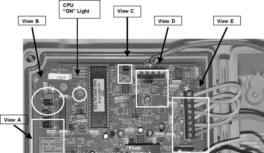
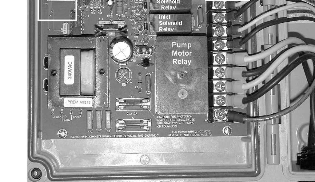
31 INSTALLATION/WIRING The controller is shipped from the factory preset for 240VAC operation with cables for power, RO pump motor and inlet solenoid installed. If the unit is equipped with flush, a flush solenoid cable is also installed. Power/Output Wiring Verify that the controller is jumpered correctly for the operating voltage. The voltage jumpers are located in the lower left corner of the control board. For 240VAC operation, one jumper is installed between J4 and J5. For 120VAC operation, one jumper is installed between J3 and J4 and a second jumper is installed between J5 and J6. Connect the pump and solenoid cables to the end devices and install the correct plug on the power cable for the selected voltage. NOTE: The pump and solenoid outputs will be the same voltage as the controller. Input Wiring The TDS cell connects to P3 and the wiring is color-coded. Connect the low pressure, pretreat and level switches to the corresponding terminals of P2. The unit is configured for normally closed inputs. All inputs must be closed for the controller to run. If any input is unused, a jumper wire must be installed for that input before the unit will run. NOTE: These inputs are for dry contact switches only. Applying voltage to these inputs will damage the controller. OPERATION The controller has a two-position power switch to control the operating mode of the controller. With the switch in the left position, POWER OFF, the controller and all outputs are off. If the switch is moved to the right position, AUTOMATIC, the controller is in the automatic mode. In this mode, the controller operation is automatic and is controlled by the input signals. Auto Mode When the switch is placed in the AUTOMATIC position, the inlet solenoid will operate and the controller will monitor the low pressure switch until a tank full condition exists. The RO pump will start after the RO start delay if no shutdown condition is present.
32 Low Pressure If a low pressure condition occurs and the low pressure switch input opens for the low pressure delay time, the controller will turn off the pump due to a low pressure fault. The red Low Pressure lamp will light. If the auto reset jumper (J9) is in the A position, the controller will remain in the low pressure until reset. The controller is reset by placing the power switch in the POWER OFF position for several seconds and then returning it to the AUTOMATIC position. Auto Reset If the auto reset jumper (J9) is in the B position when a low pressure shut down occurs, the unit will attempt to restart after the auto reset delay. If the low pressure condition has cleared, the unit will continue to run normally. Otherwise, the unit will again shut down and the auto restart cycle will continue as long as the low pressure condition is active. Pretreat If the pretreat lockout switch opens for the pretreat delay time,the unit will shut down for a pretreat condition. The amber Pre-treat lamp will light. The unit will remain shut down until the pretreat switch closes. The unit will then restart and continue to run normally. Tank Full The controller is designed to operate with either 1 or 2 tank level switches. When a tank full condition occurs, the unit will shut down and the amber Tank Full lamp will light. When the tank full condition clears, the unit will restart after the tank full restart delay. If the unit is operated with only 1 level switch, the Tank Full Low input must remain jumpered. In this mode, when the tank full high switch opens for the tank full delay time the unit will shutdown. When the tank full condition clears, the unit will restart. If the unit is operated with 2 level switches, the controller will run when both switches are closed. When the water level rises and the tank full low switch opens, the unit will continue to run. When the water level rises and the tank full high switch opens, after the tank full delay, the unit will shut down for tank full. As the tank level drops and the tank full high switch closes, the unit will remain shut down. When the level drops and the tank full low switch closes, the unit will restart. NOTE: For both 1 and 2 tank level switch configurations, the float ball or level control switch contacts MUST BE NORMALLY CLOSED when no water is present in the tank.
33 Flush If the flush option is installed, either of two modes of flush may be selected using jumper J11. If J11 is in the A position, the unit will enter a flush mode every 10 hours. This flush will occur whether the unit is running or not. When the flush occurs, the inlet and flush solenoids will open and the RO pump will start. The amber Flush lamp will light. The flush will last for 5 minutes. NOTE: A low pressure or pretreat condition will cancel the flush operation. NOTE: If the unit is shutdown for long periods of time due to a tank full condition, there is the possibility of tank overflow because of water produced during the flush cycle. If J11 is in the B position, the unit will enter a 5 minute flush each time a tank full condition occurs. After the flush time has expired, the unit will shutdown for the tank full condition. TDS The 3 digit LED TDS display can be configured for either or 0-999PPM. Two pin jumper S2 is used to select the proper range. Both jumpers must be in either the LO or HI position for proper operation. NOTE: The unit is shipped calibrated for the low range. If the range is changed in the field, the unit must be recalibrated. If the TDS reading exceeds the selected range, the display will show uuu to indicate an overrange condition. The unit may be calibrated with an on board calibration resistor or using standard solutions. To calibrate using the calibration resistor, disconnect the white wire from P3. Move jumper J13 to the A position. For the low range, adjust the CAL adjustment, R46 for a reading of 148. For the high range, adjust the CAL adjustment, R46 for a reading of 225. Move jumper J13 to the B position and reconnect the white wire to P3. To calibrate with a standard solution, place the cell in the standard and adjust the CAL adjustment for the correct reading. A TDS limit can be enabled using the SETPOINT adjustment, R53. To set the limit, move jumper J8 to the B position. The display will now show the current setting for the setpoint adjustment. While J8 is in the B position, the display will briefly show ccc to indicate that the display is showing the setpoint calibration value. Turn R53 to get the desired setpoint value. If the adjustment is turned to a value of 999, the setpoint limit is disabled. Move J8 to the A position to display the current TDS value. If the TDS value exceeds the setpoint, the TDS display will slowly blink to indicate a high TDS condition.
34 A high TDS shutdown can be enabled by moving J10 to the B position. When the shutdown is enabled and the TDS exceeds the limit, a 10 minute delay is started. If the TDS remains above the setpoint for this delay, the unit will shutdown. The TDS display will rapidly blink to indicate the cause of the shutdown. The unit will remain shutdown even if the TDS drops below the limit. The shutdown can be reset by moving the power switch to the off position for several seconds and then back to Auto.
35


36 View A View B View E
37 CE2 CONTROLLER W/FLUSH & TDS

38 CE2 CONTROLLER W/FLUSH & TDS VAC, 3PH, 60HZ 1 3 HP

39 CE2 CONTROLLER W/FLUSH & TDS VAC, 3PH, 50HZ, 1-5HP 220V, 3PH, 50HZ, 1-3HP

40 CE2 CONTROLLER W/FLUSH & TDS 380VAC, 3PH, 50HZ 1-3HP

41 CE2 CONTROLLER W/FLUSH & TDS 460VAC, 3PH, 60HZ 3HP
42
43 Appendix B: Booster Pump Operation & Maintenance Manual
44
45 Operating Instructions & Parts Manual Please read and save these instructions. Read carefully before attempting to assemble, install, operate or maintain the product described. Protect yourself and others by observing all safety information. Failure to comply with instructions could result in personal injury and/or property damage! Retain instructions for future reference. FW B Supersedes 0611 Pressure Booster Pumps Description Unpacking Pressure booster pumps increase water pressure from city mains or private water When unpacking the unit, inspect systems. Applications include providing high water pressure for washing buildings, dairy carefully for any damage that may walls or floors, hog parlors, poultry houses, rinsing or spray cooling equipment, lawn have occurred during transit. sprinkling and insecticide spraying. Stainless steel models can handle salt-water and contaminated water in reverse osmosis filter and other aggressive water applications. Use pump with clear water only. Single-phase models are equipped with a capacitor start, thermal protected motor. Three-phase models require separate overload protection. H Inlet I Discharge J G D A C B Figure 1 F E IL Hz Motor Driven Pump Dimensions (See Figure 1) Chart A Stainless Stainless Steel Dimensions In Inches Lbs. Ship Steel Fitted 3 Phase A B C D E F G H I J Wt. DPM02 DPM14 DPM16 DPM120 - DPM121 DPM52 DPM /4 3-1/4 3-1/4 3-1/4 3-3/4 3-3/4 3-3/4 3-3/4 13-3/8 16-5/ /8 18-1/2 3-7/8 3-7/8 3-7/8 3-7/8 6-1/2 6-1/2 6-1/2 6-1/2 23-7/8 27-3/ /8 30-1/2 7-1/2 7-1/2 7-1/2 7-1/2 1-7/16 1-7/16 1-7/16 1-7/16 3/4 3/4 3/4 1 3/4 3/4 3/ Hz Motor Driven Pump Dimensions (See Figure 1) DPM05 DPM04 DPM03-3-1/4 3-1/4 3-3/4 3-3/4 23-1/2 24-1/16 3-7/8 3-7/8 6-1/2 6-1/ /16 7-1/2 7-1/2 1-7/16 1-7/16 3/4 3/4 3/4 3/ (*) NOTE: Figure 1, holes in mounting base are open slotted 3/8 wide x 1/2 long; dimension A & B are centerline from these open slotted holes. These holes are suitable for 1/4 to 3/8 bolts. Dimensions also apply to three phase models. 1 CRANE ENVIRONMENTAL 730 Commerce Drive, Venice, FL
46 Stainless Steel Fitted PERFORMANCE SPECIFICATIONS PRESSURE ADDED - PSI Powder- Coated Cast Iron Fitted HP Stage Output - Gallons per Minute Max. Press. PSI Suction Pipe Tap NPT Disch. Pipe Tap NPT DPM02-3/ /4 3/4 DPM14/DPM * * /4 3/4 DPM16/DPM52-1-1/2 16 * * DPM120 DPM * * Example: If DPM02 pump is connected to supply line of sufficient capacity, carrying water at 40 PSI, and the output of the pump is held to 12.2 GPM by a gate valve, the pump will add 40 PSI to line pressure for a total output pressure of 80 PSI. * Operation of pump in this range may result in reduced pump life and/or motor damage. To keep pump and seal lubricated, a minimum flow of 1.5 GPM must always be maintained through the pump. Motor voltage: Single Phase 1/3-2 HP - 115/230; 3 HP - 230V 60 Hz. Three Phase 1/2-2 HP /460, 50/60Hz. Three Phase 3 HP /460, 60 HZ Single Phase Motor Data 60HZ HP Motor Single Phase 60 Hz 3450 RPM Capacitor Start Factory Connected Service Factor Motor Amps Locked Rotor Motor Amps Voltage Motor Voltage 115V 230V 115V 230V 3/4 115/ V / V /2 115/ V / V V Single Phase Motor Data 50HZ Single Phase 50 Hz 2850 RPM Capacitor Start 1 115/ V /2 115/ V V Thermal overload protector - automatic reset Chart C Code Letter K L J H D K K H 2 CRANE ENVIRONMENTAL 730 Commerce Drive, Venice, FL
47 Three Phase Motor Data HP Motor Three Phase 60/50 Hz 3450/2850 RPM Capacitor Start Factory Connected Voltage Motor Voltage / V 1-1/ / V / V / V 3 HP, 3 Phase motor operable on 60Hz only. Service Factor Motor Amps Locked Rotor Motor Amps 230V 460V 230V 460V Chart D Code Letter K K K D Material Construction Component Motor Bearings Impellers Diffuser Diffuser plates Pump shaft Pump shaft coupling Pump shell Discharge & inlet casting O-Rings Seal composition Chart E Stainless Steel Models Rear access - Nema 56J face Ball-ball, permanently lubricated Noryl with 304 stainless steel bearing insert Noryl Delrin 303 Stainless steel 316 Stainless steel 304 Stainless steel 304 Stainless steel Viton Carbon-ceramic, stainless steel spring and Viton Minimum Wire Size Chart (Gauge) Chart F Distance In Feet From Motor To Service Panel Motor Breaker Size Volts Phase HP (Amps) Wire Size 3/4 115/ /14 12/14 10/14 10/12 8/12 20/ / /14 10/14 10/12 8/12 6/10 30/ /2 115/ /12 8/12 6/12 */10 */10 30/ / /12 8/12 6/12 */10 */10 30/ /4 230/ /14 14/14 14/14 14/14 14/14 15/ / /14 14/14 14/14 14/14 12/14 15/ /2 230/ /14 14/14 14/14 12/14 12/14 15/ / /14 14/14 14/14 12/14 10/12 15/ / /14 14/14 14/14 12/14 10/12 15/15 (*) Not economical to run in 115V, use 230V. 3 CRANE ENVIRONMENTAL 730 Commerce Drive, Venice, FL
48 General Safety Information Carefully read and follow all safety instructions in this manual and on pump. Keep safety labels in good condition. Replace missing or damaged safety labels. This is a SAFETY ALERT SYMBOL. When you see this symbol on the pump or in the manual, look for one of the following signal words and be alert to the potential for personal injury or property damage. Warns of hazards that WILL cause serious personal injury, death or major property damage if ignored.! Warns of hazards that CAN cause serious personal injury or death, if ignored. Warns of hazards that MAY cause minor personal injury, product or property damage if ignored. IMPORTANT: Indicates factors concerned with operation, installation, assembly or maintenance which could result in damage to the machine or equipment if ignored. NOTE: Indicates special instructions which are important but are not related to hazards.! Hazardous voltage. Can shock, burn or cause death. Ground pump before connecting to power supply. Wire motor for correct voltage. See Electrical section and Motor Data Charts C&D of this manual, and motor nameplate. Ground motor before connecting to power supply. Meet United States National Electrical Code and local codes for all wiring. Do not handle a pump or pump motor with wet hands or when standing on a wet or damp surface or in water. Follow wiring instructions in this manual when connecting to power lines.! Always disconnect power source before performing any work on or near the motor or its connected load. 9. Do not insert finger or any object into pump or motor openings. 10. Secure the discharge line before starting the pump. An unsecured discharge line will whip, possibly causing personal injury and/or property damage or puncture. Do not touch an operating motor or engine. They are designed to operate at high temperatures.! This product contains chemicals known to the State of California to cause cancer and birth defects or other reproductive harm.! Risk of Electric Shock. This pump has not been investigated for use in swimming pool areas. NOTE: Pumps with the CSA-CUS mark are tested to UL standard UL778 and certified to CSA standard C22.2 No Pre-Installation HANDLING Avoid impact on pump or motor. In particular, avoid impact on discharge end of pump or rear motor access cover. LOCATION! In any installation where property damage and/or personal injury might result from an inoperative or leaking pump due to power outages, discharge line blockage, or any other reason, a backup system(s) should be used. 1. Locate pump as close to the fluid source as possible, keeping the inlet pipe short as possible. 2. Place unit where the pump and piping are protected from the weather and extremes of heat, humidity and below freezing temperatures. 3. Mount unit in a dry location that is easily accessible for inspection and maintenance. If a dry location is not available, mount it on a foundation well above the wet floor. 4. Allow ample clearance around unit for free air circulation. SUCTION LIMITATIONS 1. Units are non self-priming. 2. Pressure booster pumps are not recommended for suction lift applications. PIPING 1. Use galvanized piping, rigid plastic or other suitable pipe that will not collapse under suction or rupture due to pressure. Do not use to pump flammable or explosive fluids such as gasoline, fuel oil, kerosene, etc. Do not use in flammable and/or explosive atmospheres. Hazardous pressure! Install pressure relief valve in discharge pipe. Release all pressure on system before working on any component. 1. Make workshop child proof - use padlocks, master switches; remove starter keys. 2. Wear safety glasses when working with pumps. 3. Wear a face shield and proper apparel when pumping hazardous chemicals. 4. Keep work area clean, uncluttered and properly lighted; replace all unused tools and equipment. 5. Provide guarding around moving parts. 6. Keep visitors at a safe distance from the work area. 7. Periodically inspect pump and system components. 8. Protect electrical cord. Replace or repair damaged or worn cords immediately. 4 If hose is used, make sure it is the reinforced industrial type that is rated higher than the shutoff pressure of the system. Ordinary garden hose will collapse and starve the pump of water. 2. The diameter of the inlet and discharge pipe should be no smaller than the corresponding ports of the pump (See Figure 1). Smaller pipe will reduce the capacity of the pump. Increase pipe size on long runs. 3. Avoid air pockets in inlet piping or air will accumulate at high points, making priming difficult. 4. Use pipe compound on all joints and connections. Use Teflon tape or plastic joint stik, on plastic pipe. Draw all pipe up tightly. IMPORTANT: The entire system must be air and water tight for efficient/proper operation. CRANE ENVIRONMENTAL 730 Commerce Drive, Venice, FL
49 Installation PUMP INSTALLATION IMPORTANT: Pump is built to handle clear water only; it is not designed to handle water containing sand, silt or other abrasives. 1.Refer to Figures 6, 7, and 8 for typical installations. No Sags Sags Allow Air Pockets No Air Leaks In Inlet Pipe If Air Flows Water Won t Pipe Joint Compound Will Damage Plastic IL0419 Support pump and piping when assembling and when installed. Failure to do so may cause piping to break, pump to fail, motor bearing failures, etc. 2. If the pump is used as part of a permanent installation, bolt to a rigid foundation.! Use only components that are rated for maximum pressure pump can produce when used in boosting system or any other system. Do not exceed the total maximum pressure boost as listed per model in Performance Charts B. PRESSURE BOOST SYSTEMS 1. On pressure boost systems, locate the pump so that there will always be a positive supply of water to the pump (See Figures 6, 7 and 8). 2. For service convenience, install a gate valve and union in the inlet and discharge line. If Air Pockets Form, Water Won t Flow Figure 2 - No Air Pockets in Inlet Pipe Mount pump in correct position or pump failure will result. Correct Figure 4A IL1013 IL0418 IL0420 Use Teflon Tape Figure 3 - Inlet Pipe Must Not Leak Figure 4B Incorrect Do not use a globe valve or other restricting type of valve that will seriously restrict the pumps discharge capacity. 3. Install a check valve as shown in Figure 6. Be sure check valve flow arrows point in the direction of water flow. 4. Whenever dirt, sand or debris is present in the supply water, install a strainer or filter on the inlet side of the pump (See Figure 7). NOTE: For heavy amounts of sediment, install a trap filter on the inlet side of the pump (See Figure 5). NOTE: Pressure gauges installed before and after the filter will show pressure differential indicating the need for filter replacement or cleaning. Standard Pressure Tank - 42 Gallon Or Larger Inlet Sand Settles To The Bottom SAND AND SEDIMENT TRAP FILTER IL0421 Outlet Clean Out Figure 5 IMPORTANT: Clean all filters and strainers on a regular schedule. IL CRANE ENVIRONMENTAL 730 Commerce Drive, Venice, FL
50 Installation (Continued) 5. A pressure gauge installed in the inlet pipe close to the inlet port, (See Figure 6) will show if enough water is being supplied to the pump. See Operation Section - Priming, Pressure Boost Installations. 6. On installations that are using nozzles for mist spraying, install a filter in the discharge plumbing to prevent the nozzles from becoming plugged. Multiple filters should be plumbed in parallel.! Install a pressure relief valve on any installation where pump pressure can exceed the pressure tank s maximum working pressure or on systems where the discharge line can be shut off or obstructed. Extreme over pressure can result in personal injury or property damage. This unit is not waterproof and is not intended to be used in showers, saunas or other potentially wet locations. The motor is designed to be used in a clean dry location with access to an adequate supply of cooling air. Ambient temperature around the motor should not exceed 104ºF (40ºC). For outdoor installations, motor must be protected by a cover that does not block airflow to and around the motor. This unit is not weatherproof nor is it able to be submersed in water or any other liquid. To avoid dangerous or fatal electrical shock, turn off power to motor before working on electrical connections. Supply voltage must be within ± 10% of nameplate voltage. Incorrect voltage can cause fire or seriously damage motor and voids warranty. If in doubt, consult a licensed electrician. Use wire size specified in wiring Chart F. If possible, connect pump to a separate branch circuit with no other appliances on it. If motor wiring diagram differs from diagram shown below, follow diagram on motor. Pump used to boost incoming city pressure (automatic operation). Street Supply Check Valve Union Check Valve Gate/ Ball Valve (Normally open) Gate/ Ball Valve (Normally open) Pressure Gauge Union Service Tee Pressure Switch To size tank properly - Match drawdown of tank to capacity of pump Pressure Switch IL0422 Drain Pressure Relief Valve Figure 6 IMPORTANT: A contained air pressure tank and pressure switch is required to keep the pump from rapid cycling and prevent the motor from over heating. Install the tank and switch on the house side of system. Pump used to boost water pressure in mist spray applications (automatic operation). Fuse Box or Switch Pressure Gauge Thermostat Figure 7 Inlet Line Filter Pressure Relief Valve Outlet Solenoid Valve To Drain NOTE: Install solenoid valve on discharge side of pump. IMPORTANT: Clean all filters and strainers on a regular schedule. IL0423 Pressure Gauge Main Power Box Union Fuse Box or Switch Gate/Ball Valve From Water Source Gate/Ball Valve (Normally open) To Nozzles 6 CRANE ENVIRONMENTAL 730 Commerce Drive, Venice, FL
51 Installation (Continued)! Hazardous voltage. Can shock, burn or cause death. Ground pump before connecting to power supply. Ground motor before connecting to electrical power supply. Failure to ground motor can cause severe or fatal electrical shock hazard. Do not ground to a gas supply line. Proper rotation of pump impeller is critical on three phase motors. See Motor Rotation under Operation section and Figure 12. WIRING 1. Install, ground, wire and maintain this pump in accordance with your local electrical code and all other codes and ordinances that apply. Consult your local building inspector for local code information. 2. Ground the pump permanently using a wire of size and type specified by local or United States National Electrical Code. Do not ground to a gas supply line. 3.Connect ground wire first. Connect to ground first, then to green grounding terminal provided on the motor frame, identified as GRD. Ground connection MUST be made to this terminal. Do not connect motor to electrical power supply until unit is permanently grounded; otherwise serious or fatal electrical shock hazard may be caused. 4. Connect the other end of the ground wire to a properly grounded service panel or to a control panel ground bar if it is connected to the power supply ground. IMPORTANT: Check local and/or United States National Electric Codes for proper grounding information. Make certain that the power supply conforms to the electrical specifications of the motor supplied. See Motor Data Charts. Pump used to boost incoming pressure from a wall hydrant (manual operation). Hose Adapter Wall Hydrant Pressure Gauge Pressure Relief Valve Service Tee Hose Adapter High Pressure Reinforced Hose Inlet Figure 8 Y E L L O W L1 W H I T E 115 Volts Single Phase A G R A Y L1 Line B A L2 Spray Nozzle 230 Volts Single Phase Line B Outlet High Pressure Reinforced Hose 230 Volts Single Phase L2 Line IL0180 NOTE: Dual voltage motors, change the red and gray wire to the voltage required. Figure 9 - Wiring Diagram for Single Phase 1/3-2 HP Motors Y G E R L A L Y O W IL0181 NOTE: Single voltage (230V) motor, and can not be connected to 115V. Figure 10 - Wiring Diagram for Single Phase 3 HP Motors R E D T A N Y E L L O W L1 A W H I T E G R A Y B R E D L2 T A N IL CRANE ENVIRONMENTAL 730 Commerce Drive, Venice, FL
52 Installation (Continued) 5.Specific Wiring Procedure (Refer to Figures 9, 10, & 11 and Minimum Wire Size Chart). a. Select the voltage you are to use, either 115V or 230V single phase, 230V or 460V three phase. b. The 1/3, 1/2 and 3/4 HP single phase pumps are factory connected for 115V at the motor. The 1, 1 1 /2, 2 and 3 HP pumps are factory connected for 230V at the motor. Three phase models are factory connected for 230V at the motor. c. If the motor wiring must be changed to conform to your specific voltage requirements then the motor, pressure switch or other controls should be rewired to conform to one of the wiring diagrams (either 115V or 230V, single phase; 230V or 460V, three phase). Single phase 3 HP motors are 230V only and cannot be wired for 115V service. d. The motor wiring diagrams are Figures 9, 10, & 11 and also are located on the motor label of the pump. 6. Remove the rear access cover of the motor. 7. Make the wiring change and replace the rear access cover.! Replace rear access cover before starting or operating pump. Failure to do so can result in personal injury. IMPORTANT: Do not use an extension cord or splice wires. Joints should be made in an approved junction box. If the above information or the following wiring diagrams are confusing, consult a licensed electrician. 8. All units are not supplied with pressure switches, float devices, on/off switches, or the like (control devices). Controls should be wired in at this time, utilizing whatever instructions come with the controls. All units supplied with cords, will run whenever cord is plugged into power and will turn off whenever cord is disconnected from power. MOTOR PROTECTION All single phase motors have built in thermal protection for all voltages. The overload protects the motor against burnout from overload of low voltage, high voltage and other causes. The device is automatic and resets itself once the temperature has dropped to a safe point. Frequent tripping of the device indicates trouble in the motor or power lines and immediate attention is needed.! Never examine, make wiring changes or touch the motor before disconnecting the main electrical supply switch. The thermal device may have opened the electrical circuit. Three phase motors do not have a built in thermal protection. It is recommended that a properly sized magnetic or manual starter (both with properly sized heaters) be used with all three phase motors. Install starters following instructions of the starter manufacturer. See Motor Rotation under Operation Section for changing rotation on three phase motors. All motors (single and three phase) should be equipped with a correctly fused disconnect switch to provide protection. Consult local or United States National Electric Codes for proper fuse protection based on motor data chart (See Charts C, D and Wire chart F). Low Voltage 230V Operation L 1 L 2 L 3 IL0182 High Voltage 460V Unit must be full of fluid before operating. Do not run dry, or against a closed discharge. Do not pump dirty water or abrasive liquids. To do so will cause pump failure and will void the warranty. VALVES The inlet valve should be in the full open position and the discharge valve should be partially open, permitting some back pressure to be exerted against the pump when starting up. Open valve after start up is completed. PRIMING NOTE: Before starting the pump it is absolutely necessary that both the pump and the inlet pipe be completely filled with water. PRESSURE BOOST INSTALLATIONS Priming is automatic when pump is connected to a pressure source such as a hydrant or city main (See Figures 6, 7 & 8). 1. Open valves or nozzle on inlet and discharge side of pump 2. To relieve trapped air, allow water supply to run a minimum of 30 seconds before starting the pump. IMPORTANT: An adequate flow of water going into the pump is required so that the pumps impellers and shaft seal do not run dry and fail. 3. If you installed a pressure gauge at the pump inlet, a read ing of 2 psi minimum should show whenever the pump is in operation (See Figures 6, 7 & 8). This reading insures that there is an ample supply of water into the pump inlet housing L 1 L 2 L Tan 4 - Yellow 7 - Purple 2 - Red 5 - Black 8 - Gray 3 - Orange 6 - Blue 9 - White CONNECTION FOR 3 PHASE, 9 LEADS. IF YOUR 3 PHASE LEADS ARE COLOR CODED, MATCH NUMBER ABOVE TO THE CORRESPONDING COLOR. NOTE: To reverse rotation, interchange any two incoming lines (Power) leads. Figure 11 - Wiring Diagram for Three Phase Motors 8 CRANE ENVIRONMENTAL 730 Commerce Drive, Venice, FL
53 Operation (Continued) MOTOR/PUMP ROTATION 1. Single phase models are one (1) rotation only (counterclockwise when facing the pump end) and cannot be reversed. 2. Proper rotation of pump impeller is critical for three phase pumps. Pump motor should turn counterclockwise (CCW) when facing pump end. Momentarily bump (apply power for less than a second) the motor to check for proper rotation. To change rotation on three phase units, interchange any two (2) incoming line (power) leads. Do not go over recommended maximum operating pressure (see Specifications), while maintaining minimum flow of 1.5 GPM thru the pump. Do not restrict the inlet line to the pump. If driver (electric motor) is overloaded, a valve can be installed in the discharge line to increase the back pressure and reduce driver loading. START - UP PROCEDURE Once the preceding instructions have been completed, the pump can be started. 1. During the first few hours of operation, inspect the pump, piping and any auxiliary equipment used in connection with the unit. 2. Check for leaks, excessive vibration or unusual noises. Figure 12 - Correct Motor/Pump Rotation (all units) NOTE: See rotation arrow on inlet casting. Maintenance IL0539 Disconnect power supply and depressurize system before servicing pump or removing any component. ROUTINE Pump should be checked routinely for proper operation. Replace or clean all filters and line strainers on a regular basis. DRAINING This pump cannot be completely drained because of internal design. Most of the liquid can be drained by tilting the discharge forward after removing discharge casting; or, the liquid can be drained through the inlet port. Store in heated areas. CLEANING If used for spraying insecticides, pump should be thoroughly flushed with clean water after using. LUBRICATION The motor has prelubricated bearings. No lubrication is required. SERVICING THREE-PHASE UNITS Loctite (thread sealer) is used on the threads between the motor shaft and the pump shaft coupling. When reassembling, reapply thread sealer. PUMP DISASSEMBLY To disassemble the pump, refer to the exploded parts view, Figures 17 & 18 Tools Required Block of wood (2 x 4 x 12 ) Piece of 3/4 pipe (12 to 24 long) Pipe wrench Strap wrench 1/4 Dowel rod (about 24 long) 9/16 Open end wrench 3/8 Open end wrench or 3/8 deep well socket 1. To stabilize pump during disassembly, place block of wood underneath pump barrel. 2. Thread pipe into pump inlet port. This acts as a handle. 3. Using the pipe wrench, remove the discharge head, turning CCW (counter clockwise). 4. With the strap wrench, loosen the barrel, turning CCW (counter clockwise). DO NOT use pipe wrench on pump barrel. 5. Holding the impeller stack in place, position pump in upright position, standing unit on the motor end cover. 6. Use the 1/4 dowel rod to hold the stages down and in place on the pump shaft. Remove pump barrel. 7. With the pump set in the vertical position, remove the top stage and carefully set aside. WARNING: Do not remove the pump shaft from the cartridge for any reason! If the shaft is removed from cartridge, consult factory customer service at number listed below. 8. Through the side opening of the mounting frame, hold the motor shaft with 9/16 wrench. Remove the shaft and coupling from the motor using the 3/8 wrench or deep well socket on the hex shaped pump shaft. NOTE: If the hex shaft comes free, leaving the coupling attached to the motor, use vise grips to free the coupling. MECHANICAL SEAL REPLACEMENT 1. Follow instructions under Pump Disassembly. 2. Remove the mechanical seal assembly. a. The rotary portion of the seal assembly (carbon ring, Viton gasket and spring will slide easily off the end of shaft). b. Using two (2) screwdrivers, pry the ceramic seal and rubber gasket from the recess of the mounting ring (See Figure 14). The precision lapped faces of the mechanical seal are easily damaged. Handle the replacement seal carefully. Short seal life will result if seal faces (ceramic & carbon) are nicked, scratched or dirty. 3. Clean the seal cavity of the mounting ring and the motor thoroughly. 4. Wet outer edge of rubber cup on ceramic seat with liquid soap solution. Use sparingly (one drop only). 9 CRANE ENVIRONMENTAL 730 Commerce Drive, Venice, FL
54 Maintenance (Continued) NOTE: Liquid soap solution - one drop of liquid soap combined with one teaspoonful of water. 5. With thumb pressure, press ceramic seal half firmly and squarely into seal cavity. Polished face of ceramic seat is up. If seal will not seat correctly, remove, placing seal face up on bench. Reclean cavity. Seal should now seat correctly (See Figure 14). 6. If seal does not seat correctly after recleaning cavity, place a cardboard washer over polished seal face and carefully press into place using a piece of standard clean 3/4 pipe as a press (See Figure 15). IMPORTANT: Do not scratch seal face. 7. Dispose of cardboard washer and recheck seal face to be sure it is free of dirt, foreign particles, scratches and grease. 8. Inspect shaft to be sure it is free of nicks and scratches. 9. Apply liquid soap solution sparingly (one drop is sufficient) to inside diameter of rubber rotating member. 10. Slide rotating seal member (carbon face down toward ceramic face) and spring over the shaft. IMPORTANT: Do not nick or scratch carbon face of seal when handling. MOTOR REPLACEMENT The motor can be replaced with any standard Nema 56J jet pump motor (of proper HP for each pump) by referring to the following instructions. 1. Follow steps as outlined under Rotary Seal Replacement and Pump Disassembly. 2. Remove cap screws that connect the motor to the mounting ring and pull motor away. 3. Replace motor with standard Nema 56J jet pump motor by positioning motor against the mounting frame and assembling with four (4) cap screws. IMPORTANT: Because damage to the shaft seal can occur in disassembly, a new seal will be necessary. PUMP REASSEMBLY Before reassembling the pump, carefully inspect the component parts of the cartridge (stage) assembly, looking for damage, wear or heat distortion. Pay careful attention to spacing direction of components, and location of shims. Refer to Figure 16 for proper facing and parts arrangement. If damage to Stage components is evident, a complete cartridge assembly or individual stage assemblies are available for replacement (See Replacement Parts List). 1. Reassembly should follow the reverse order of the disassembly procedure with special care given to replacement of the rotary seal. Tighten pump shaft to 8-10 Ft. lbs. torque. 2. Check top and bottom of o-rings for damage. It is recommended that new o-rings be used. 3. Do not use pipe compound of Teflon tape on barrel threads. The o-rings will prevent pump from leaking. 4. After pump is reassembled, tighten the discharge head to a torque of ft/lbs. If torque wrench is not available, tighten firmly but avoid distortion or damage to plastic internal parts. 5. After reassembly, apply power momentarily to unit (15 to 30 seconds). The pump and motor should rotate freely or with a light rubbing. 3/4 Pipe Press Carefully Cardboard Washer Protects Seal Face Seal Seal Cavity Figure 13 - Remove Mechanical Seal Figure 14 - Press In Seal Figure 15 - If Necessary, Press With Cardboard And Pipe IL CRANE ENVIRONMENTAL 730 Commerce Drive, Venice, FL
55 Troubleshooting Chart Symptom Possible Cause(s) Corrective Action Pump won t start or run at full speed Pump operates, but delivers little or no water 1. Blown fuse or open circuit breaker 1. Replace fuse or close circuit breaker. See wire size chart for proper break/fuse size 2. Power supply in OFF position 2. Turn power on 3. Incorrect voltage at motor (check voltage with motor running) 3. Low voltage a. Voltage must be within ± 10% of motor rated voltage. Check incoming voltage. Contact power company b. Make certain that voltage of motor matches voltage of power supply. See motor name plate and motor wiring diagrams c. Check wire size from main switch to pump. See wire size chart for correct wire size 4. Loose, broken or incorrect wiring 4. Rewire any incorrect circuits. Tighten connections, replace defective wires 5. Defective motor 5. Replace motor 6. Pump hydraulic components clogged/ worn/damaged 6. Replace worn parts or entire pump. Clean parts if required 1. Manual or solenoid valves plumbed into system restricting flow 1. a Check all valves on pump inlet and discharge sides of system to be sure they are opened properly to allow flow to and from the pump b. Bleed trapped air in pump which keeps water from reaching the pump. (Normally due to closed valve in discharge plumbing) 2. In-line filter restricting flow 2. Check all in-line filters to be sure they are not plugged or restricted 3. Low line voltage 3. See low line voltage corrective action (above) 4. Inadequate water supply to booster pump 4. Check pressure on inlet side of booster to be sure positive pressure is maintained to the booster pump 5. Undersized piping 5. Replace undersized piping 6. Leak on inlet side of system 6. Make sure connections are tight. Repair leaks as necessary 7. Inadequate, defective or plugged foot 7. Clean, repair or replace as needed valve and/or strainer 8. Worn or defective pump parts or 8. Replace worn parts or entire plugged impeller Clean parts if pump. 9. Suction lift too great 9. Pump should be operated under flooded suction only 10. Pump not primed 10. Prime pump - Make certain inlet pipe is drawn up tight and pump and pipe are full of water 11. Incorrect rotation, motor running backwards 11. Reverse motor rotation can occur on three phase units. To correct, interchange any two incoming power leads. Excessive 1. Pump not secured to firm foundation 1. Secure properly noise while 2. Piping not supported 2. Make necessary adjustments pump in 3. Restricted inlet line 3. Clean or correct 4. Cavitation (noise like marbles in pump) 4. a. Reduce speed on direct drive b. Increase inlet pipe size c. Too viscous (material being pumped too thick 5. Worn motor bearings 5. Replace bearings or motor Pump leaks 1. Worn mechanical seal (leaks at shaft) 1. Replace shaft (rotary) seal 2. Worn o-ring seals 2. Replace o-ring seals, located inside both ends of the stainless steel shell 11 CRANE ENVIRONMENTAL 730 Commerce Drive, Venice, FL
56 Booster Pump Parts Drawing ITEM NO. DESCRIPTION 1 Screws, Access Cover (2) 2 MotorAccess Cover 3 Switch Motor 4 Governor 5 Motor 6 Mounting Ring 7 Hex Head Shaft Bolts (4) 8 Seal, Rotary 9 O-ring (2) 10 Shaft and Coupling Assembly 11 Plate, Diffuser 12 Impeller 13 Shim as Required 14 Diffuser Bearing 15 Diffuser 16 Barrel 17 Discharge Bearing 18 Discharge Head *See note below parts included in cartridge assembly IL Internal Parts Detail IL0308 Figure 16 - Cartridge Assembly Includes Discharge Bearing, Shaft & Coupling Assembly, Diffuser Plate, Impellers, Diffuser Bearings and Diffusers NOTE: Illustration shows only two stages. Pump has multiple stages. Individual parts are not available separately. 12 CRANE ENVIRONMENTAL 730 Commerce Drive, Venice, FL
57 PRESSURE BOOSTER PUMP REPAIR PARTS STAINLESS STEEL BOOSTER PUMP 60 Hz (For Pricing Refer To Repair Parts Price List) IL ITEM HORSEPOWER 3/ /2 SINGLE DPM02 DPM14 DPM16 STAINLESS STEEL PHASE MODEL NO. THREE - DPM121 DPM52 PHASE DESCRIPTION PART NO. Motor, 1 PH Nema J Motor, 3 PH Nema J Motor Access Cover Screws, Access Cover Seal, Rotary w/spring - Viton Barrel Discharge Head - Stainless Steel O-Ring, Viton Cartridge Assembly Shaft & Coupling Assembly R S S110 98S S115 98S Mounting Ring - Stainless Steel Hex Hd. Cap Screws 3/8 x 3/4 * Rain Cover ITEM STAINLESS STEEL HORSEPOWER 3 SINGLE PHASE MODEL NO. DPM120 THREE PHASE DPM150 DESCRIPTION PART NO. QUANTITY 98S630 98S R * * Motor, 1 PH Nema J 1 Motor, 3 PH Nema J Motor Access Cover Screws, Access Cover p Hex Hd. Cap Screws 3/8 x 1 3 Seal, Rotary w/spring - Viton 4 Barrel 5 Discharge Head - Stainless Steel 6 O-Ring, Viton 7 Cartridge Assembly 8 Shaft & Coupling Assembly 9 Mounting Ring - Stainless Steel Hex Hd. Cap Screws 3/8 x 3/4 Rain Cover (*) Standard hardware item ( ) Not shown ( ) Cartridge assembly includes: Impeller, Diffusers, Shaft and Coupling Assembly. Components not available individually. Sold as assembly only. (2) Handle available as an option 13 CRANE ENVIRONMENTAL 730 Commerce Drive, Venice, FL
58 PRESSURE BOOSTER PUMP REPAIR PARTS STAINLESS STEEL BOOSTER PUMP 50 Hz (For Pricing Refer To Repair Parts Price List) IL STAINLESS STEEL BOOSTER PUMP 50 Hz HORSEPOWER 1 1-1/2 STAINLESS STEEL SINGLE PHASE MODEL NO. DPM05 DPM04 ITEM DESCRIPTION PART NO. QUANTITY 1 Motor, 1 PH Nema J 98S010 98S015 Motor Access Cover Screws, Access Cover R Seal, Rotary w/spring - Viton Barrel Discharge Head - Stainless Steel O-Ring - Viton Cartridge Assembly Shaft & Coupling Assembly Mounting Ring - S.S. Hex Hd. Cap Screws 3/8 x 3/4 Rain Cover (*) Consult factory ( ) Cartridge assembly includes: Impeller, Diffusers, Shaft & Coupling Assembly. Components not available individually. Sold as assembly only. ( ) Not shown (2) Handle available as an option WARRANTY This product is warranted for one year from the date of purchase or two years from the date of manufacture, whichever occurs first. Subject to the conditions hereinafter set forth, the manufacturer will repair or replace to the original consumer, any portion of the product which proves defective due to defective materials or workmanship. To obtain warranty service, contact the dealer from whom the product was purchased. The manufacturer retains the sole right and option to determine whether to repair or replace defective equipment, parts or components. Damage due to conditions beyond the control of the manufacturer is not covered by this warranty. THIS WARRANTY WILL NOT APPLY: (a) To defects or malfunctions resulting from failure to properly install, operate or maintain the unit in accordance with printed instructions provided; (b) to failures resulting from abuse, accident or negligence or use of inappropriate chemicals or additives in the water; (c) to normal maintenance services and the parts used in connection with such service; (d) to units which are not installed in accordance with normal applicable local codes, ordinances and good trade practices; and (e) the unit is used for purposes other than for what it was designed and manufactured. RETURN OF WARRANTED COMPONENTS: Any item to be repaired or replaced under this warranty must be returned to the manufacturer at Kendallville, Indiana or such other place as the manufacturer may designate, freight prepaid. 14 THE WARRANTY PROVIDED HEREIN IS IN LIEU OF ALL OTHER EXPRESS WARRANTIES, AND MAY NOT BE EXTENDED OR MODIFIED BY ANYONE. ANY IMPLIED WARRANTIES SHALL BE LIMITED TO THE PERIOD OF THE LIMITED WARRANTY AND THEREAFTER ALL SUCH IMPLIED WARRANTIES ARE DISCLAIMED AND EXCLUDED. THE MANUFACTURER SHALL NOT, UNDER ANY CIRCUMSTANCES, BE LIABLE FOR INCIDENTAL, CONSEQUENTIAL OR SPECIAL DAMAGES, SUCH AS, BUT NOT LIMITED TO DAMAGE TO, OR LOSS OF, OTHER PROPERTY OR EQUIPMENT, LOSS OF PROFITS, INCONVENIENCE, OR OTHER INCIDENTAL OR CONSEQUENTIAL DAMAGES OF ANY TYPE OR NATURE. THE LIABILITY OF THE MANUFACTURER SHALL NOT EXCEED THE PRICE OF THE PRODUCT UPON WHICH SUCH LIABILITY IS BASED. This warranty gives you specific legal rights, and you may have other rights which vary from state to state. Some states do not allow limitations on duration of implied warranties or exclusion of incidental or consequential damages, so the above limitations may not apply to you. WARRANTY VALID IN CANADA AND MEXICO. CRANE ENVIRONMENTAL 730 Commerce Drive, Venice, FL
59 Appendix C: Activated Carbon Filter Manual
60
 19 GPM Peak (25 psi drop) 24 GPM CV (flow at 1 psi drop) 4.8 Max.")

61 Model 2510 Control Valve FRONT WITHOUT COVER BACK Valve Specifications Valve material Fiber reinforced polymer Inlet/Outlet 3/4, 1 or 1-1/4 Cycles 5 Flow Rates (50 psi Inlet) - Valve Alone Continuous (15 psi drop) 19 GPM Peak (25 psi drop) 24 GPM CV (flow at 1 psi drop) 4.8 Max. backwash (25 psi drop) 17 GPM Product Features Fully adjustable 5-cycle top mount control delivers controlled upflow backwash, downflow brining and slow rinse, rapid rinse, brine refill and downflow service Time-tested hydraulically balanced piston, seal and spacer concept to control service flow and regeneration Non-corrosive, high-tech material construction Excellent flow rates 19 GPM continuous, 24 GPM peak Backwash capacity handles tanks up to 16 diameter for softener applications, 16 diameter for filter applications Choice of 7 or 12 day clock, manual or meter initiated regeneration, mechanical or electronic control Options Corrosion-free bypass valve Backwash filter Meter initiated regeneration Manual operation Environmental cover No hard water bypass piston Auxiliary switches Regeneration Downflow/Upflow Adjustable cycles Time available Downflow only Yes Electromechanical: 164 minutes SE: 0-99 minutes ET: minutes Meter Information Meter accuracy range GPM +/- 5% Meter capacity range (gal.) Standard: 125-2,125 Extended: ,625 SE: 1-9,999 ET: 1-9,999,999 Dimensions Distributor pilot 1.05 O.D. Drain line 1/2 O.D. Brine line /8, /8 Mounting base 2-1/2-8 NPSM Height from top of tank 7-1/2 Typical Applications Water softener Iron filter Sediment filter Carbon filter Neutralizing filter 6-16 diameter (limited by maximum injector size) 8-16 diameter (based on 10 GPM per sq. ft.) 8-16 diameter (based on 10 GPM per sq. ft.) 8-16 diameter (based on 10 GPM per sq. ft.) 8-16 diameter (based on 10 GPM per sq. ft.) Additional Information Injector brine system 1600 Electrical rating 24 v, 110 v, 220 v - 50 Hz, 60 Hz Max. VA 72 Estimated shipping weight Time clock: 7 lbs. Metered valve: 10 lbs. Pressure Hydrostatic: 300 psi Working: psi Temperature F
62
63 Appendix D: Activated Carbon Filter Start Up Procedures
64
65 ACTIVATED CARBON FILTER START-UP PROCEDURES (AUTOMATIC or MANUAL) The Carbon Filter is shipped with DRY activated Carbon media that MUST BE HYDRATED with water for 24 hours (12 hours minimum) before placing the unit into service mode. Failure to properly HYDRATE the activated Carbon media and perform the following backwashing procedures may allow Carbon ash or fines to enter into the RO system causing premature fouling of the RO membranes. (Damage to membranes due to Carbon fines, sediment fouling or scaling is not covered under warranty for replacement.) If the Carbon filter has been shipped preloaded with activated Carbon media, install the controller valve head per the manufacturer s instruction manual and proceed to step #1. If the Carbon filter has been shipped with loose activated Carbon media, load the activated Carbon media on site into the filter vessels per the manufacturer s instruction manual, install the controller valve head and proceed to step #1. NOTE: FILL the filter vessel approximately 1/3 full with clean water before loading the under-bed gravel or Carbon media to avoid possible breakage of the lower distributor. 1. Connect the feedwater, backwash drain and service lines to the filter s controller unit per the manufacturer s instruction manual included with the unit. Allow a 6-8 air gap on the drain line connection to the main drain. 2. Connect the proper electrical power connections for automatic control units, per the manufacturer s instruction manual included with the unit. 3. Direct the service outlet line from the Carbon filter to the drain during the initial startup backwashing procedures. (DO NOT direct water from the new service outlet side of the Carbon filter into the RO unit until the Carbon filter backwash procedure has been completed.) 4. Manually place the controller valve into the backwash position or electrically advance the control valve to the backwash mode and then unplug the control valve. Close off the service outlet line with an isolation ball valve. Direct the feedwater supply slowly into the control valve until all air has been vented out of the Carbon tank. After the air has been vented off and a steady flow of water is observed into the drain, you may open the feedwater supply fully to pressurize the tank and establish full backwash flow. 5. Allow the Carbon media to backwash and sample the drain water with a clean WHITE cup. You may observe that the water is partially black with some Carbon ash or fines settling to the bottom of the cup. Continue backwashing until the water becomes clear as sampled with the WHITE cup. This may initially take minutes or longer depending on the amount of Carbon media loaded into the tank. CAUTION: IF EXCESSIVE AMOUNTS OF CARBON MEDIA CONTINUES TO DISCHARGE TO THE DRAIN DURING BACKWASH STOP! (1) The backwash flow controller orifice maybe installed incorrectly (2) The flow during backwash is too high. (3) The lower lateral screen may be cracked. Remove the control valve and inspect and/or repair.
66 6. Manually place the unit into the RINSE/SETTLE position and allow the media to settle for the next minutes. 7. Manually place the unit into the SERVICE position. Open the isolation valve on the service outlet line and observe the water out of the service line directed to the drain. Perform the WHITE cup sample tests until the water is clear. Stop the water flow into the Activated Carbon Filter and close the feedwater inlet ball valve and the outlet service line ball valve. Allow the Activated Carbon media to HYDRATE for 24 hours (12 hours minimum). 8. After HYDRATION of the media, perform steps 1 through 7 at least 3-4 more times to remove all loose Carbon ash and fines throughout the media bed. 9. Perform a Chlorine test before the Carbon filter and record the PPM level of Chlorine residual. 10. Perform a Chlorine test after the Carbon filter and record the PPM level of Chlorine residual. (CHLORINE RESIDUAL MUST BE ZERO for feedwater supply to the RO unit.) Perform the WHITE cup test again; the water should be clear with NO Carbon ash or fines present. 11. If Chlorine is still present, check the installation of the controller valve. The upper o-rings in the control valve may not be seated properly to the distributor pipe or the distributor pipe is cut too short. Verify proper flow design through the Carbon filter to prevent channeling due to low flow or high flow conditions. It may be possible that the Chlorine residual level is too high at your site and you do not have enough Carbon media for proper contact time to absorb the Chlorine residual. NOTE: If the feedwater supply has Chloramines used for disinfection, it will require 4-6 times more Carbon media to remove the Chloramines residual from the feedwater supply. Should you have any problems or require additional assistance, please call your Crane Environmental Representative or Dealer for assistance.
67 Appendix E: Technical Field Service Information
68

69 EPRO OPERATION AND MAINTENANCE MANUAL (REVISED 4/11) 45


70 EPRO OPERATION AND MAINTENANCE MANUAL (REVISED 4/11) 46
71 Appendix F: Terms & Conditions / Limited Warranty
72
73
74

75
OPERATING MANUAL. Reverse Osmosis Equipment Model: Frame Mount Vertical FMV-1 through FMV-6. Made in U.S.A.
 OPERATING MANUAL Reverse Osmosis Equipment Model: Frame Mount Vertical FMV-1 through FMV-6 Made in U.S.A. TABLE OF CONTENTS Model: Frame Mount Vertical COMPONENT IDENTIFICATION Page 1 IMAGE OF R. O. SYSTEM
Spot Free Reverse Osmosis Rinse System
 Spot Free Reverse Osmosis Rinse System CONTENTS 2016 TOMMY CAR WASH SYSTEMS General Instructions... 2 Overview of RO System... 2 Key Reverse Osmosis System Terms... 5 Requirements... 8 Feed Water Pre-treatment
EXTREME 1 Reverse Osmosis System
 EXTREME 1 Reverse Osmosis System Leader Evaporator Co., Inc. 49 Jonergin Drive Swanton, VT 05488 Tel: 802-868-5444 www.leaderevaporator.com TABLE OF CONTENTS INTRODUCTION... 4 THEORY OF OPERATION... 4
GROWMAX WATER Perfect Water for Plants and Gardens
 GROWMAX WATER Perfect Water for Plants and Gardens WATER SYSTEMS FOR HYDROPONICS AND GARDENING GROWMAX 3000 Ultra-Pure Reverse Osmosis Water System Up to 3000 L/D of Pure Water Don't forget to register
WM-450-PT WM-900-PT Commercial Wall Mounted Reverse Osmosis
 WM-450-PT WM-900-PT Commercial Wall Mounted Reverse Osmosis Installation And Service Manual Watts Pure Water 1725 W. Williams Dr. C-20., Phoenix, Arizona 85027 Phone: 888-774-7405 Fax: 602-588-0356 www.wattspurewater.com
EXTREME HP-1 Reverse Osmosis System
 EXTREME HP-1 Reverse Osmosis System Leader Evaporator Co., Inc. 49 Jonergin Drive Swanton, VT 05488 Tel: 802-868-5444 www.leaderevaporator.com TABLE OF CONTENTS INTRODUCTION... 4 THEORY OF OPERATION...
EXTREME HC-2 Reverse Osmosis System
 EXTREME HC-2 Reverse Osmosis System Leader Evaporator Co., Inc. 49 Jonergin Drive Swanton, VT 05488 Tel: 802-868-5444 www.leaderevaporator.com Contents INTRODUCTION... 3 THEORY OF OPERATION... 4 Terms...
PRF-RO Pentair Reverse Osmosis System Installation and Maintenance Manual SAFETY GUIDES THE BASIC REVERSE OSMOSIS SYSTEM. Tools and Materials Required
 PRF-RO Pentair Reverse Osmosis System Installation and Maintenance Manual SAFETY GUIDES Read and follow all steps and guides carefully before installing and using your reverse osmosis system. Do not use
EXTREME 2 Reverse Osmosis System
 EXTREME 2 Reverse Osmosis System Leader Evaporator Co., Inc. 49 Jonergin Drive Swanton, VT 05488 Tel: 802-868-5444 www.leaderevaporator.com TABLE OF CONTENTS INTRODUCTION... 4 THEORY OF OPERATION... 4
EXTREME HC-4 Reverse Osmosis System Leader Evaporator Co., Inc. 49 Jonergin Drive Swanton, VT Tel:
 [Type a quote from the document or the summary of an interesting point. You can position the text box anywhere in the document. Use the Drawing Tools tab to change the formatting of the pull quote text
EXTREME HC-8 Reverse Osmosis System
 EXTREME HC-8 Reverse Osmosis System Leader Evaporator Co., Inc. 49 Jonergin Drive Swanton, VT 05488 Tel: 802-868-5444 www.leaderevaporator.com TABLE OF CONTENTS INTRODUCTION... 4 THEORY OF OPERATION...
Installation & Service Guide
 Reverse Osmosis Ontario Soft Water.ca Kitchener, Canada 519-579-0500 Installation & Service Guide Pentair 75 gpd Encapsulated Membrane System Standard System 75gpd Membrane Your New Reverse Osmosis System
AQUA ONE. Reverse Osmosis System Model ARO5000. Installation and Service Guide PLEASE READ THIS MANUAL CAREFULLY BEFORE ATTEMPTING INSTALLATION
 AQUA ONE Reverse Osmosis System Model ARO5000 Congratulations on your purchase of the most sophisticated water purifier system available! Installation and Service Guide PLEASE READ THIS MANUAL CAREFULLY
EXTREME 4 Reverse Osmosis System
 EXTREME 4 Reverse Osmosis System Leader Evaporator Co., Inc. 49 Jonergin Drive Swanton, VT 05488 Tel: 802-868-5444 www.leaderevaporator.com TABLE OF CONTENTS INTRODUCTION... 4 THEORY OF OPERATION... 4
26/06/2018 USER MANUAL OSMOSE HOBBY GPH. All rights reserved Les Équipements d Érablière CDL inc.
 26/06/2018 USER MANUAL OSMOSE HOBBY 100-200 GPH All rights reserved Les Équipements d Érablière CDL inc. Thank you for purchasing a CDL Hobby reverse osmosis system. This document will help you make the
26/06/2018 USER MANUAL HOBBY 100 GPH REVERSE OSMOSIS. All Rights reserved Les Équipements d Érablière CDL inc.
 26/06/2018 USER MANUAL HOBBY 100 GPH REVERSE OSMOSIS All Rights reserved Les Équipements d Érablière CDL inc. Thank you for purchasing a CDL Hobby reverse osmosis system. This document will help you make
MKTF CRO-Series 5-Stage Reverse Osmosis System Installation and Maintenance Manual
 MKTF - 215 CRO-Series 5-Stage Reverse Osmosis System Installation and Maintenance Manual Please fill out the following information at the time of installation. Save for future reference. Model: Date Code:
INSTALLATION & SERVICE MANUAL
 INSTALLATION & SERVICE MANUAL Countertop Reverse Osmosis Systems Series CT System Tested and Certified by WQA against NSF/ANSI Standard 58 for the reduction of Arsenic, Barium, Cadmium, Copper, Cyst, Hexavalent
475 PRO SERIES Reverse Osmosis System Installation & Operation Manual
 PLEASE READ ALL INSTRUCTIONS BEFORE INSTALLING AND USING THIS SYSTEM 475 PRO SERIES Reverse Osmosis System Installation & Operation Manual Model STAGE 1 STAGE 2 STAGE 3 STAGE 4 OUTPUT 475 SEDIMENT CARBON
REVERSE OSMOSIS SYSTEMS
 REVERSE OSMOSIS SYSTEMS TABLE OF CONTENTS R.O. SYSTEM DESCRIPTION... 2 R.O. EQUIPMENT INSTALLATION...3 R.O. SYSTEM CHECK-OUT PROCEDURE... 4 R.O. UNIT TURN ON PROCEDURE...5 R.O. UNIT RATING.. 6 R.O. BAY
Table of Contents. List of Figures
 1 P a g e Table of Contents Introduction. 3 Receiving....4 Description Model G3 & G4...5/6 Water Production Flow Chart...7 Positioning the Cooler...8 Water Cooler Connections..9 Feed Water Connection....10
1 P a g e. G4 Counter Top OPERATION MANUAL
 1 P a g e G4 Counter Top OPERATION MANUAL Table of Contents Introduction. 3 Receiving....4 Description Model G3 & G4...5/6 Water Production Flow Chart...7 Positioning the Cooler...8 Water Cooler Connections..9
Operating Manual. Reverse Osmosis Water Purifier. MELAdem 55
 Operating Manual Reverse Osmosis Water Purifier MELAdem 55 Dear Doctor, Thank you for placing your trust in this reverse osmosis water purifier. Since 1951, MELAG has specialised in the production of sterilisation
Plumbline 2000 Series Metered Softeners Owners Manual Water Softener Models
 Plumbline 2000 Series Metered Softeners Owners Manual Water Softener Models PS2000M PS2500M PS2700M PS2900M Table of Contents How to Use Soft Water 3 Product Line Overview 5 System Operation 6 System Maintenance
GRANT-DILLING-HARRIS INC. WATER SOFTENER THEORY OF OPERATION
 GRANT-DILLING-HARRIS INC. WATER SOFTENER THEORY OF OPERATION WATER SOFTENER: The Water Softener requires a 120VAC 2 AMP electrical service and the Water lines in and out need to be sized to the Softener.
INSTALLATION & SERVICE MANUAL
 INSTALLATION & SERVICE MANUAL Countertop Reverse Osmosis Systems Series CT CT-315 CT-315TFC CT-445 CT-445P CT-D425 CT-D425P CT-550UP 3 STAGE CTA RO SYSTEM 3 STAGE TFC RO SYSTEM 4 STAGE TFC RO SYSTEM 4
WS1 Softener Installation & Start-Up Guide
 WS1 Softener Installation & Start-Up Guide Thank you for purchasing a Van Isle Conditioner. With proper installation and a little routine maintenance your system will be providing treated water for many
Owner's Manual. WS Series. Water Softener
 Owner's Manual WS-165-150 Series Water Softener Table of Contents WHAT'S INCLUDED 3 OPERATING CONDITIONS 4 ASSEMBLY INSTRUCTIONS 6 FLUSHING THE WATER LINES 13 MASTERPROGRAMMING 14 PROGRAMMING KEYAND GENERAL
TEMPLATE ASSISTED CRYSTALLIZATION. Presented By Ryan Lessing 11/13/2014
 TEMPLATE ASSISTED CRYSTALLIZATION Presented By Ryan Lessing 11/13/2014 Different Forms of Hardness in Water Calcium and Magnesium Bicarbonate- This is what is referred to as temporary hardness. Once it
LC Series - Light Commercial Pump Station Installation and Operation Manual
 LC Series - Light Commercial Pump Station Installation and Operation Manual Please keep this manual with the pump station Content Rain Bird LC Series Overview... Safety Instruction... Operation... 3 Pump
REVERSE OSMOSIS DRINKING WATER SYSTEM
 REVERSE OSMOSIS DRINKING WATER SYSTEM INSTALLATION, OPERATION & SERVICE MANUAL Drink With Confidence! TABLE OF CONTENTS SECTION I. Page INTRODUCTION...3 SECTION II. SPECIFICATIONS...4 SECTION III. SECTION
Tap Master Artesian Hydro Gardener Series Installation & Service Manual
 Perfect Water Technologies 7 Tips for an Easy and Successful Installation 1. Keep it simple - there are 3 connections to make, and the tubing is color coded. 2. Have plenty of time, light, space, and towels
R.O. DRINKING WATER SYSTEM
 R.O. DRINKING WATER SYSTEM INSTALLATION, OPERATION & SERVICE MANUAL IMPORTANT NOTICES: This reverse osmosis system contains replaceable treatment components critical for effective performance. It is the
SERVICE MANUAL. Bradford White ElectriFLEX HD (Heavy Duty) Commercial Electric Water Heater CEHD SERIES Immersion Thermostat Models
 Commercial Electric Water Heater CEHD SERIES Immersion Thermostat Models") Bradford White ElectriFLEX HD (Heavy Duty) Commercial Electric Water Heater CEHD SERIES Immersion Thermostat Models SERVICE MANUAL Troubleshooting Guide and Instructions for Service (To be performed ONLY
Bradford White ElectriFLEX HD (Heavy Duty) Commercial Electric Water Heater CEHD SERIES Immersion Thermostat Models SERVICE MANUAL Troubleshooting Guide and Instructions for Service (To be performed ONLY
The Coffee Professor Reverse Osmosis System Model Genesis Cafe
 The Coffee Professor Reverse Osmosis System Model Genesis Cafe Congratulations on your purchase of the most advanced water purifier system available! Installation and Service Guide PLEASE READ THIS MANUAL
FLECK 5600 WATER SOFTENER INSTALLATION
 FLECK 5600 WATER SOFTENER INSTALLATION Discount Water Softeners recommends using a licensed plumber to install your water softener. The following installation instructions are for use with the water softener
J-PRO-22 Pump Proportional Feed Chlorinator Installation & Start-Up Guide
 J-PRO-22 Pump Proportional Feed Chlorinator Installation & Start-Up Guide Thank you for purchasing a Clean Water System! Please review this start-up guide entirely before beginning to install your system
Owner s Manual RD432-0 Chemical Controller
 Owner s Manual RD432-0 Chemical Controller Table of Contents I. Introduction page 2 A. Water Chemistry page 2 B. Safety page 3 C. System Components page 4 D. Specifications page 7 E. Controller Panel Descriptions
1020 Industrial Drive, Orlinda, TN fax
 Operation Manual UPT Medical Reverse Osmosis System K-RO-UPT Series 615-654-4441 sales@specialtyh2o.com 615-654-4449 fax TABLE OF CONTENTS Section 1 GENERAL 1.1 Warnings and Cautions... 1 1.2 Theory of
Plumbline 1000 Series Timered Softeners Owners Manual Water Softener Models
 Plumbline 1000 Series Timered Softeners Owners Manual Water Softener Models PS1000T PS1500T Table of Contents How to Use Soft Water 3 Product Line Overview 5 System Operation 6 System Maintenance and Install
Puratek Aquarium Reverse Osmosis Installation and Maintenance Manual
 Puratek Aquarium Reverse Osmosis Installation and Maintenance Manual Thank You for your purchase of a Puratek System by Vertex Aquaristik. With proper installation and maintenance, this system will provide
Model 8780 INSTALLATION, OPERATION & MAINTENANCE INSTRUCTIONS. Tempering Skid General Area Classification & Class I Division 2. No.
 INSTALLATION, OPERATION & MAINTENANCE INSTRUCTIONS 1455 Kleppe Lane Sparks, NV 89431-6467 (775) 359-4712 Fax (775) 359-7424 E-mail: haws@hawsco.com Website: www.hawsco.com Model 8780 Tempering Skid General
Ultraviolet Water Sterilizer Installation and Maintenance Manual
 Ultraviolet Water Sterilizer Installation and Maintenance Manual (Models:GP-UV6W, GP-UV12W, GP-UV55W) INSTALLERS: PLEASE READ ALL INSTRUCTIONS BEFORE INSTALLING AND USING THIS SYSTEM. PERFORMANCE IS GUARANTEED
1850 Series TRIPLE TREAT Operation Manual
 1850 Series TRIPLE TREAT Operation Manual BRINE TANK RESIN TANK CARBON TANK System shown with optional tank jackets. Note: 1. Read all instructions carefully before operation. 2. Avoid pinched o-rings
CEHA Fall Chloride Workshop. Chloride Treatment Options Presented by Paul Hurlbut Professional Water Systems, Inc.
 CEHA Fall Chloride Workshop Chloride Treatment Options Presented by Paul Hurlbut Professional Water Systems, Inc. Being Aware of a Problem The sodium and chloride problem is nothing new. What is new is
WATER FILTRATION SYSTEM (RO5) OWNER S MANUAL
 OWNER S MANUAL") WATER FILTRATION SYSTEM (RO5) OWNER S MANUAL 1 INTRODUCTION Congratulations on choosing Permatech to improve the quality of your water. You will immediately notice the numerous benefits of having quality
WATER FILTRATION SYSTEM (RO5) OWNER S MANUAL 1 INTRODUCTION Congratulations on choosing Permatech to improve the quality of your water. You will immediately notice the numerous benefits of having quality
Model #: PT3000T36-GOLD
 Good Water Warehouse Inc. 1700 E Walnut Ave Fullerton CA 92831 (714) 441-2893 (714) 441-0525 FAX Reverse Osmosis System Installation & Service Guide Model #: PT3000T36-GOLD Do not use with water that is
PWC 1800 PureWaterCooler SERVICE MANUAL. for. PureWaterCooler by Vertex Model PWC P/N man Copyright 2011 Vertex Water Products
 SERVICE MANUAL for by Vertex Model PWC-1800 P/N man-7011 Table of Contents 1. Introduction 2. Cooler Set-up 3. Remove Top Cover 4. Remove/Replace Float 5. Remove/Replace Hot Tank 6. Dispensing Solenoid
Spectrum TM. Installation, Service & Operation Manual O FLO. SoftH 2. Water Softener. Table of Contents
 Installation, Service & Operation Manual SoftH 2 O FLO Water Softener Table of Contents 1. Description & Equipment Adjustments p.2 2. Components, Features & Functions p.3 3. Valve User Interface p.4 4.
254 Nanometer Germicidal UV Disinfection Systems
 For Commercial and Industrial Applications ES-PW-SmartStream-C _D Job Name Contractor Job Location Approval Engineer Contractor s P.O. No. Approval Representative 254 Nanometer Germicidal UV Disinfection
Fully Automatic Water Softeners
 OWNERS GUIDE TO INSTALLATION AND OPERATION Fully Automatic Water Softeners SINGLE TANK CABINET MODELS TWO TANK MODELS Read the instructions carefully and learn the specific details regarding installation
VMS-3. Part Number: Ultraviolet Systems VMS-3. Installation, Operation & Maintenance
 VMS-3 Part Number: 95-0031 Ultraviolet Systems VMS-3 Installation, Operation & Maintenance The following are the types of flags used in this technical manual. They designate safety related items and important
INSTRUCTIONS FOR E-SERIES WATER PURIFICATION MACHINES 57,000 GPD TO 288,000 GPD 216 M3/D to 1090 M3/D OPERATION AND MAINTENANCE MANUAL
 INSTRUCTIONS FOR E-SERIES WATER PURIFICATION MACHINES 57,000 GPD TO 288,000 GPD 216 M3/D to 1090 M3/D OPERATION AND MAINTENANCE MANUAL TABLE OF CONTENTS 1.0 DESCRIPTION................................................................
Rules for Safe Operation
 Rules for Safe Operation Important: Do not attempt to operate the CleanStation until you have read thoroughly and understand all instructions and safety rules contained in this manual. Failure to comply
SYSTEMS for CATALYTIC FILTERS
 OP40U5F, OP40B5F, OP80U10F, OP80B10F, OP120U15F & OP120B15F INSTALLATION, OPERATION & SERVICE INSTRUCTIONS Hydrogen Sulfide Removal SYSTEMS for CATALYTIC FILTERS NO DIAPHRAGMS OR AIR CELLS COMPLETELY CORROSION
7800 Neutralizer Installation & Start-Up Guide
 Clean Water Made Easy www.cleanwaterstore.com 7800 Neutralizer Installation & Start-Up Guide Thank you for purchasing a Clean Water System! With proper installation and a little routine maintenance your
BLAST-IT-ALL BUMPER BLASTER
 LARRY HESS AND ASSOCIATES, INC 185 PIPER LANE / SALISBURY, NC 28147 PHONE: 1-800-535-2612 / FAX: 1-704-638-9311 WWW.BLAST-IT-ALL.COM BLAST-IT-ALL BUMPER BLASTER SUCTION BLAST CABINET NOTE: It is the responsibility
Installation and Operation Manual
 How To Install, Operate and Maintain Your Reverse Osmosis System FILTER CARTRIDGE CONFIGURATION MAY BE SUBJECT TO CHANGE. 475 PRO SERIES 475BP PRO SERIES INSTALLERS: PLEASE READ ALL INSTRUCTIONS BEFORE
Installation, Operation, and Maintenance Manual. Waterlogix Metered Residential Water Softener
 Installation, Operation, and Maintenance Manual Waterlogix Metered Residential Water Softener Waterlogix WLS-075 Waterlogix WLS-075C Waterlogix WLS-100 Waterlogix WLS-100C Waterlogix WLS-150 Waterlogix
IMPORTANT SAFETY INFORMATION READ ALL...
 INSTALLATION and SERVICE MANUAL HOUSEPURE MODELS HP03 and HP04 736-0137 Table of Contents IMPORTANT SAFETY INFORMATION READ ALL... 3 P/N 41482 Rev A 06/04 INSTRUCTIONS BEFORE USING... 3 FEEDWATER... 4
Owner s Manual AQ-RO-BASE. Aquasana OptimH2O Drinking Water System Reverse Osmosis Filtration Technology
 Owner s Manual AQ-RO-BASE Aquasana Drinking Water System Reverse Osmosis Filtration Technology Welcome to the Aquasana experience. You are about to enjoy clean, clear water and the peace of mind that comes
PRE-ASSEMBLED RADIANT CONTROL PANEL INSTALLATION MANUAL
 FloorHeat PRE-ASSEMBLED RADIANT CONTROL PANEL INSTALLATION MANUAL Thank you for purchasing this radiant control panel assembly. Following are some important notes that will make the installation successful.
J-PRO-24 Pump Chlorinator. Installation & Start-Up Guide
 J-PRO-24 Pump Chlorinator Installation & Start-Up Guide Thank you for purchasing a Clean Water System! With proper installation and a little routine maintenance, your system will be providing treated water
Reverse Osmosis System OWNERS MANUAL
 APS Water Services Corporation Quick Change, Twist & Loc Reverse Osmosis System OWNERS MANUAL Installation, Operation & Maintenance Sold By : APS Water Services Corp 818-786-0600 NOTE: Please read through
INSTALLATION MANUAL CRS-3
 INSTALLATION MANUAL CRS-3 12630 US 33 N. Churubusco, IN 46723 Ph. (260)693-1972 Fax (260)693-0602 www.sterlingwatertreatment.com 1 TABLE OF CONTENTS: SECTION I. SECTION II. INTRODUCTION...3 SPECIFICATIONS...3
Installation and Operation Manual
 How To Install, Operate and Maintain Your Reverse Osmosis System INSTALLERS: PLEASE READ ALL INSTRUCTIONS BEFORE IN- STALLING AND USING THIS SYSTEM. IT IS RECOMMENDED TO WAIT UNTIL THE ENTIRE SYSTEM IS
Fully Automatic Water Softeners
 OWNERS GUIDE TO INSTALLATION AND OPERATION Fully Automatic Water Softeners FW0782 0211 Supersedes 0410 Models S15DC29DR and S15DC39DR SAFETY INFORMATION Read the instructions carefully and learn the specific
Technical Specifications & Pricing
 Nu/Clean Model 510 Recirculating Water Deionizer Inline Aqueous Cleaning System for Closed Loop, Zero Discharge Operations Technical Specifications & Pricing The base machine in its standard configuration
Installation, Operation, and Maintenance Manual RTE14S & RTE14S-2. For the Taco Bell "Rethermalizer" Model Numbers
 Installation, Operation, and Maintenance Manual For the Taco Bell "Rethermalizer" Model Numbers RTE14S & RTE14S-2 NOTICES There are three different types of notices that you should be familiar with, a
Fleck 5600 SXT. Installation Guide. Make a list of all of the plumbing fittings needed to install; a typical list looks like this:
 Installation Guide Before you assemble your new system, be sure that the following conditions have been met for placement of your softener: Getting Started Level, firm surface, such as concrete, on which
Water Softener & Single Tank Triple Treat System Installation Overview. Using 1850 Metered Valves
 Water Softener & Single Tank Triple Treat System Installation Overview Using 1850 Metered Valves System Installation CAUTION: Do not use systems on untreated well water that is microbiologically unsafe.
WS1 Greensand Installation & Start Up Guide
 WS1 Greensand Installation & Start Up Guide Thank you for purchasing a WS1 Water System for the removal of iron, manganese and hydrogen sulphide gas. With proper installation and a little routine maintenance
Installation, Operation, and Maintenance Manual
 Installation, Operation, and Maintenance Manual Product Preservers Anti-Scale System Chemical-Free, Salt-Free Scale Prevention Introduction The Product Preservers Anti-Scale System will condition the tap
TM Series. Induced Draft, Counter Flow Optional Accessories
 ANTIFREEZE PACKAGE / RESISTANCE HEATING OPTION The antifreeze package is supplied to provide protection against freezing of standing water in the cooling tower sump due to shutdown during winter operation.
WATER FILTRATION SYSTEM (RO6) OWNER S MANUAL
 OWNER S MANUAL") WATER FILTRATION SYSTEM (RO6) OWNER S MANUAL 1 INTRODUCTION Congratulations on choosing Permatech to improve the quality of your water. You will immediately notice the numerous benefits of having quality
WATER FILTRATION SYSTEM (RO6) OWNER S MANUAL 1 INTRODUCTION Congratulations on choosing Permatech to improve the quality of your water. You will immediately notice the numerous benefits of having quality
BarAid 400. Installation and. Starting from Serial No.:
 Glasswasher BarAid 400 Installation and operation Instructions Starting from Serial No.: 8649 1065 REV. 19.01.2009 DE 1618-A-01-09 Content Page 1 Important Notes... 4 2 Installation... 5 2.1 Location...
TITAN SYSTEM ENGINEERING DATA SHEET TITAN HXS
 This document and specifications are the property of REsys and shall not be reproduced or disseminated other than for recipients use for internal evaluation of REsys prices and product specifications.
OPERATION AND INSTRUCTION MANUAL NORCLEAN POWERED EDDY CURRENT VACUUM RECOVERY SYSTEM WITH WATER TRAP OPTION
 OPERATION AND INSTRUCTION MANUAL NORCLEAN POWERED EDDY CURRENT VACUUM RECOVERY SYSTEM WITH WATER TRAP OPTION THIS SYSTEM IS TO BE USED FOR REMOVING CONTAMINATED DEBRIS FROM EDDY CURRENT PROBES DURING STEAM
Fleck 2510 Softener Installation & Start Up Guide
 Clean Water Made Easy www.cleanwaterstore.com Fleck 2510 Softener Installation & Start Up Guide Thank you for purchasing a Clean Water System! With proper installation and a little routine maintenance
Fleck 2510 SXT Catalox Installation & Start Up Guide
 Fleck 2510 SXT Catalox Installation & Start Up Guide For Catalox Filters with PotPerm Bleach Solution Tank Thank you for purchasing a Clean Water System! With proper installation and a little routine maintenance
OPERATING AND MAINTENANCE MANUAL FOR PLATE HEAT EXCHANGER INDIRECT FIRED WATER HEATER. Electric Heater Company Base Model "BWXP"
 OPERATING AND MAINTENANCE MANUAL FOR PLATE HEAT EXCHANGER INDIRECT FIRED WATER HEATER Electric Heater Company Base Model "BWXP" HUBBELL ELECTRIC HEATER COMPANY P.O. BOX 288 STRATFORD, CT 06615 PHONE: (203)
User Instructions. Visit us at us at RB5, RB10, RB15 Maple Sap Buckets
 Responsible Use and Liability Disclaimer User Instructions The products offered by The RO Bucket LLC are intended for use by individuals who have become knowledgeable regarding the reverse osmosis process
APEX Water Filters MODEL RO 5. Treat your body to pure goodness with Apex filtered water INSTRUCTION MANUAL. pure water in every drop
 APEX Water Filters pure water in every drop MODEL RO 5 INSTRUCTION MANUAL Treat your body to pure goodness with Apex filtered water A Water supply adapter valve B Cold water shut-off valve C Hot water
Kinetico 2060f OD Sulfur Guard Installation Instructions
 SAFETY GUIDELINES Read all steps, guides, and rules carefully before installing and using the Kinetico 2060f OD Sulfur Guard. Check your local building and sanitation codes for installation compliance.
Installation, Operation and Maintenance Manual for the Potable Water System Model: PWS-01 (380 VAC Suppy x 24 VDC Controls)
") Installation, Operation and Maintenance Manual for the Potable Water System Model: PWS-01 (380 VAC Suppy x 24 VDC Controls) (Part No: KI40008AB) A part of (Intentionally Blank) Approval Sheet Divex Advitium
Installation, Operation and Maintenance Manual for the Potable Water System Model: PWS-01 (380 VAC Suppy x 24 VDC Controls) (Part No: KI40008AB) A part of (Intentionally Blank) Approval Sheet Divex Advitium
Clean Water Made Easy
 Clean Water Made Easy http://www.cleanwaterstore.com Pro-OX 5700-E Iron Filter Installation & Start-Up Guide Thank you for purchasing a Clean Water System! With proper installation and a little routine
EXHAUST PURGE DESICCANT AIR DRYER INSTRUCTION & MAINTENANCE MANUAL MODEL RE-231 THROUGH RE-252
 EXHAUST PURGE DESICCANT AIR DRYER INSTRUCTION & MAINTENANCE MANUAL MODEL RE-231 THROUGH RE-252 ARROW PNEUMATICS, INC. REGENERATIVE DRYER DIVISION 500 NORTH OAKWOOD RD LAKE ZURICH, IL,60047 PHONE # (847)
RO.. DRINKING WATER SYSTEM
 MICROLINE RO.. DRINKING WATER SYSTEM MODEL C. T. A. - 3 INSTALLATION, OPERATION & SERVICE MANUAL IMPORTANT NOTICES: This reverse osmosis system contains replaceable treatment components critical for effective
WATER FILTRATION SYSTEM (USF3) OWNER S MANUAL
 OWNER S MANUAL") WATER FILTRATION SYSTEM (USF3) OWNER S MANUAL 1 INTRODUCTION Congratulations on choosing Permatech to improve the quality of your water. You will immediately begin to notice the numerous benefits of having
WATER FILTRATION SYSTEM (USF3) OWNER S MANUAL 1 INTRODUCTION Congratulations on choosing Permatech to improve the quality of your water. You will immediately begin to notice the numerous benefits of having
READ AND FOLLOW ALL INSTRUCTIONS SAVE THESE INSTRUCTIONS
 READ AND FOLLOW ALL INSTRUCTIONS SAVE THESE INSTRUCTIONS 1 IMPORTANT SAFETY INSTRUCTIONS Read the instructions The appliance is not to be used by persons (including children) with reduced physical, sensory
M790 ph/orp Controller. Owner s Manual
 M790 ph/orp Controller Owner s Manual Table of Contents I. Introduction page 2 A. Water Chemistry page 2 B. Safety page 3 C. System Components page 4 D. Specifications page 7 E. Controller Panel Descriptions
COMPASS HIGH-EFFICIENCY WET-ROTOR CIRCULATORS
 COMPASS HIGH-EFFICIENCY WET-ROTOR CIRCULATORS INSTALLATION AND OPERATING INSTRUCTIONS File No: 10.895 Date: march 8, 014 Supersedes: 10.895 Date: december 10, 013 1.0 Symbols used in this document 1.0
Fleck 5600 Carbon Filter Installation & Start Up Guide
 Clean Water Made Easy www.cleanwaterstore.com Fleck 5600 Carbon Filter Installation & Start Up Guide Thank you for purchasing a Clean Water System! With proper installation and a little routine maintenance
Fleck 7000 Sediment Filter Installation & Start-Up Guide
 Clean Water Made Easy www.cleanwaterstore.com Fleck 7000 Sediment Filter Installation & Start-Up Guide Thank you for purchasing a Clean Water System! With proper installation and a little routine maintenance
INDUSTRIAL CONDENSATE POLISHERS. LWTCP Series
 INDUSTRIAL CONDENSATE POLISHERS 150,000 TO 3,000,000 GRAINS CAPACITY (Sodium Cycle) Optimum Efficiency And Proven Reliability 1 P a g e Condensate Polishers are important in systems treating condensed
J-PRO V 230V Dual Voltage Chlorinator Installation & Start-Up Guide
 J-PRO-22 110V 230V Dual Voltage Chlorinator Installation & Start-Up Guide Thank you for purchasing a Clean Water System! With proper installation and a little routine maintenance, your system will be providing
Installation & Service Manual
 Installation & Service Manual Table of Contents Unpacking & Inspection... 2 Basic Guidelines... 2 Specifications... 3 Before Starting Installation Where to install the filter... 4 Tools, pipe, fittings
OPERATING AND MAINTENANCE MANUAL
 HYDROFILL Hydronic water treatment filling units Copyright 2016 Caleffi OPERATING AND MAINTENANCE MANUAL NA10439 www.caleffi.com NA5709 series Function HYDROFILL is a water treatment fi lling unit that
Large Direct-Pure EDI Water System. User Manual. RephiLe Bioscience, Ltd.
 Large Direct-Pure EDI Water System User Manual RephiLe Bioscience, Ltd. Table of Contents 1 Introduction 1.1 Product Features........5 1.2 Main Applications....6 1.3 Specifications...7 1.4 Operation......
MP-MBA-45T-1/60T-1 / 75T-1
 MASTER Water Conditioning Corp. www.masterwater.com Installation and Operation Manual MP-MBA-45T-1/60T-1 / 75T-1 with the 268/762 Logix Control Valve July 2006 Table of Contents Page No. Topic Description