HOT AIR GENERATOR WITH GAS BURNER NA11.45 A GGS. Installation Operation Commissioning Maintenance
|
|
|
- Aleesha Lyons
- 6 years ago
- Views:
Transcription
1 Installation Operation Commissioning Maintenance HOT AIR GENERATOR WITH GAS BURNER GGS NA11.45 A
2

3 CONTENTS 1. DESCRIPTION OF THE UNIT 2. INSTALLATION & CONNECTION 3. COMMISSIONING 4. CARE AND MAINTENANCE 5. PROBLEMS 6. CE CERTIFICATE OF CONFORMITY Note to reader: This document is provided for guidance only. Certain modifications may apply. The manufacturer shall not be held liable for potential errors or omissions in these instructions. 1
 Burner cover Flue (not supplied) Combustion chamber - Stainless steel chamber - Stainless steel exchanger - Stainless steel smoke box - Hot air deflector: zinc-plated sheet metal Tubular plate heat")

4 1. DESCRIPTION OF THE UNIT 3 CONFIGURATION TYPES: Int. burner (fig1.) Ext. burner (fig2.) Burner fixed outside (fig3.) Burner cover Flue (not supplied) Combustion chamber - Stainless steel chamber - Stainless steel exchanger - Stainless steel smoke box - Hot air deflector: zinc-plated sheet metal Tubular plate heat exchanger and smoke box Threaded condensate drain union Integrated bypass Three thermostat chamber outlet Use a differential pressure switch or another system to control the air flow (compulsory). This component is provided by CIAT service if the power and electrical control box is supplied. Fan always upstream of the combustion chamber Chamber cleaning access hatch Burner Main components: 1 air pressure switch 1 min. and max. gas pressure switch 1 ignition and safety valve block 1 gas filter 1 flame detection and control unit Burner power supply voltage: single-phase 240 V or three-phase 240/400 V; 50 Hz + Earth Burner access door Power and electrical control box (optional) Panel to access chamber cleaning hatch 3-thermostat access panel Flue, gas expansion valve, buffer tank and sectional valves not supplied 2
5 DIMENSIONS Ø D G C1 Fig.1 Fig.2 Burner casing Fig.3 3
6 TABLE OF DIMENSIONS CHAMBER P Max Kw AIR FLOW BURNERS 4
 If the air-handling unit is equipped with a fan with a 2-speed or variable-speed motor, the control must ensure that the reduction in the air flow automatically causes a")

7 UNIT dpa chamber combustion circuit dpa chamber air side Chamber weight kg m 3 / m 3 Propane x (gas flow m 3 /h) Volume of gas combustion products GN x (gas flow m /h) If the air-handling unit is equipped with a fan with a 2-speed or variable-speed motor, the control must ensure that the reduction in the air flow automatically causes a reduction in power. PICTOGRAMS Condensate drain siphon Grounding compulsory Air flow Electric heater 2. INSTALLATION & CONNECTION GAS SUPPLY For a supply pressure greater than that recommended by the burner manufacturer, a pressure expansion valve must be installed to obtain the correct value while respecting the flow. The installation must have a gas supply cutoff valve for each burner and a manual valve located at the entrance to the premises, as per the conditions set out in article GZ 15 (fire safety regulations for establishments open to the public). 5
8 Schematic diagram of the gas system Unit exterior Unit interior (when applicable) Manual safety valve (not supplied by CIAT) Expansion valve (option) Gas inlet To burner 1 m maximum Buffer tank (not supplied by CIAT) Operating pressure Natural gas: LPG: MPA = 30 to 400 mbar expansion 18 mbar MPB = 0.4 to 4 bar expansion 18 mbar/300 mbar BUTANE expansion 28 mbar/118 mbar PROPANE expansion 37 mbar/148 mbar Recommendation for calculating the pipework diameter, see following sections. The pipework must always be installed with the greatest care. The local gas distribution prescriptions must be strictly followed (in FRANCE comply with DTU 61.1). Burnt gas evacuation duct The duct should preferably be made from special gas-grade aluminium sheet with a purity of at least 99.5% or from stainless steel sheet metal. the duct is neither flush-mounted nor engraved but fixed only to the masonry using clamps. Each duct inlet is labelled to indicate that it can only be used for the evacuation of gas combustion products. The roof outlet complies with the usual standards. Minimum height of 0.40m above any ridge (sloping roof). Minimum height of 1.20m above a terrace roof (15% slope). A T-joint with an inspection cover is provided at the base. Double-wall ducts are recommended to prevent the formation of condensates. The duct cross-section must not be smaller than that of the unit's connection nozzle. The ducts are positioned at least 20 cm from any flammable material. The burnt gas ducts are made in accordance with the prescriptions of the CE directives. Flame length and flue installation principle 1 m min Flue duct (not supplied by CIAT) Condensate drain Ø 3/4" int. evacuation Ø Condensate draining 6
9 The sum of the pressure drops (flue duct + combustion chamber) must not exceed that authorised by the burner (refer to the table in the "Dimensions" section). The combustion gas outlet must extend at least 1 metre above the top of the roof. It is also necessary to check that the combustion gas cannot be recycled in the premises (allow a sufficient distance between the flue outlet and the building air inlets). The condensate drains will be connected to the gutter via a sealed duct. POWER SUPPLY AND ELECTRICAL CONNECTION All the electrical connections and wiring are configured and installed in accordance with the codes, local regulations and wiring diagrams located inside the units. Connecting the safety unit Check that the available electrical power supply corresponds to the characteristics on the manufacturer's plate. Safety thermostat mounted at the chamber outlet 1st thermostat (automatic reset) Adjustable using the knob on the thermostat housing (range from 0 to 80 C). This stage can control the ventilation units in fresh air only operation (set to approximately 25 C). 2nd thermostat (automatic reset) Adjustable inside the unit (range from 30 to 120 C). This stage provides overheating protection for the combustion chamber (set to approximately 90 C). The stage must be incorporated into the burner's control chain. 3rd thermostat (automatic reset) Adjustable inside the unit (range from 40 to 100 C). This stage provides overheating protection for the combustion chamber (set to approximately 100 C). The stage must be incorporated into the burner's control chain. Honeywell L4064N FAN and LIMIT thermostat LIMIT-2 thermostat Type TR2 Code Automatic reset LOAD FAN Damper control FAN 25 LIMIT 100 C LOAD LIMIT Manual reset Check that the strap has been correctly cut White button LINE LINE Red push button Automatic Button raised Resetting FAN FAN LIMIT LIMIT LOAD LINE LOAD LINE To be inserted in the burner control duct Combustion chamber adjustment servomotor control (1-wire control) Temperature < 25 C: damper closed Temperature > 25 C: damper open 7
10 Breaking capacity for each thermostat - 15 A (2.5 A) at 250 V - 10 A (2.5 A) at 400 V Only qualified personnel may carry out work on the thermostat. When replacing an old thermostat with a new model, remember to carry out the wiring modifications and run an operating test. VENTILATION UNITS 1. Fresh air only operation If the temperature at the chamber outlet is lower than 25 C, the combustion chamber ventilation unit is 90% closed. If the temperature at the chamber outlet is greater than 25 C, the combustion chamber ventilation unit is open. The ventilation unit can be controlled by an On/Off servomotor without a zero return (zero return by phase inversion). This servomotor may be controlled by the thermostat's 1st stage (to fine-tune the air outlet temperature setting, the servomotor may be the modulating type controlled by a modulating regulator with a supply air sensor). The servomotor will have a mechanical stop to allow the opening and closing percentages to be set (travel limit). 2. Adjusting the bypass flap To obtain the ideal temperature at the combustion chamber outlet and reduce the risk of condensation, please set the combustion chamber bypass according to the exhaust temperature (min. 160 C in the worst-case scenario). Note: the settings are given for information only; they must be fine-tuned during operation at a low return temperature. A larger bypass opening improves operation. GENERATOR For safety and maintenance reasons, please observe the clearances given below. Access side La distance between the GGS generator and the wall must be at least 900 mm (the desired distance is the depth of the GGS generator). Opposite side The distance between the GGS and the wall must be determined on the basis of how the burnt gas duct is installed (see section relating to its installation). The unit must be installed in accordance with current regulations and standards in a well-ventilated area. The unit must not be installed in an area with a risk of fire (fine flammable dust) or explosion, or in an area containing aggressive products such as trichloroethylene, perchlorate, etc. The fresh air flow required to supply combustion is at least 2 m 3 /h per kw of heat flow. GAS PIPE AND ELECTRICAL ROUTING Inside the GGS generator Observe the correct clearance for the smoke box access panel. Allow room to access the minimum gas pressure switch (adjustment). SELECTING THE BUFFER CAPACITY The volume of the buffer tank + the volume of the pipework (expansion valve at the consumption point) must be based on the maximum flow of the installation, at least: BP (16 to 21 mbar) 2 litres per Nm3 MP (0.06 to 4 bar) 1 litre per Nm3 NOTE: the buffer capacity does not compensate for undersized pipework. Required buffer capacity in litres based on the max. flow in Nm 3 /h Gas flow rate Nm 3 /h Buffer volume LP pressure Buffer volume MP pressure
11 Capacity in litres per linear metre of pipe Bore (mm) Steel Copper Polyethylene NOTE: the buffer tank is required if the volume of the pipework is less than the buffer capacity calculated. GAS PIPEWORK DIAMETER SELECTION AID Correction factor depending on altitude and temperature F = Barometric pressure + gas pressure 273 X T of gas F normal average Natural GAS l 020 mbar F = 1 LPG 37 mbar F = 1 LPG 150 mbar F = 1.1 Natural GAS 300 mbar F = 1.25 GAS FLOW RATE CALCULATION NATURAL GAS Flow rate in Nm 3 /h = Generator power (kw) NCV x efficiency If the temperature is not 0 C, the gas flow rate read on the meter must be corrected using the F coefficient determined above. PROPANE GAS Flow rate in kg = Generator power (kw) 13 kw/h x efficiency Flow rate in Nm3/h = flow rate in kg/h x 0.5 Nm 3 /kg Reminder: 1 kg of propane = 13 kw/h or 1kg/h of propane = 13 kw K: 0.5 Nm 3 / kg = kg/nm 3 (1.98 kg/nm3 = density of propane) Propane gas: to use the pipework diameter selection tables below, apply a coefficient of 1.66 to the calculated flow rate Corrected PROPANE GAS flow rate = propane flow rate x 1.66 Reminder: the pipework diameter based on the pressure drop (dp), depends on 3 criteria: Pressure downstream of the expansion valve Maximum flow rate Equivalent pipe length. 9
12 The tables give the theoretical internal diameters for straight pipes. Formed parts and accessories must be converted into straight lengths to check the influence on the selected diameter. 18 mbar Theoretical diameters for pressure = 18 mbar and dp = 1 mbar Pipe lengths in m Flow rate in Nm 3 /h 300 mbar Theoretical diameters for pressure = 300 mbar and dp = 5 mbar Pipe lengths in m Flow rate in Nm 3 /h 1 bar Theoretical diameters for pressure = 1 mbar and dp = 10 mbar Pipe lengths in m Example of pipework selection for natural gas Generator: 150 kw 150 Generator efficiency: 90% Flow rate = = 16.6 Nm 3 /h Metering Flow rate under: 300 mbar 10 x 0.9 PCl Natural in Nm 3 /h gas: 10 kw / h / m 3 Equivalent length: 40 m Pipework diameter: 31 mm minimum Buffer capacity = 1 litre per Nm3/h (16.6 litres) Example of pipework selection for propane gas Generator: 150 kw Generator efficiency: 90% Flow rate in Nm3/h: 12.8 x 0.5 = 6.4 Nm 3 /h Metering under: 150 mbar Corrected flow rate (see previous page): 6.4 Nm 3 /h x 1.66 = Nm 3 /h Natural gas NCV: 13 kw / h / m 3 Pipework diameter: 31 mm minimum* Equivalent length: 40 m Buffer capacity = 7 litres 150 Flow rate = 13 x 0.9 = 12.8 kg/h 10
13 Dimension based on bore and material The smallest required bore is selected (see table of standard dimensions below) based on the necessary theoretical internal diameter and the type of pipe. The section capacity is calculated based on the selected bore and the section length, and compared to the required buffer capacity. If the section capacity is less than the required buffer capacity, a larger bore should be selected or a buffer capacity created. The actual bore to be used is defined based the material used and the standard bores available for this material. Dimensions based on standard bore and material Bore Steel in accordance with NF A up to DN 20 inclusive and in accordance with NF A from DN 25 Copper in accordance with NF E DN mm Inch(es) external Ø mm thickness mm external Ø mm thickness mm Capacity in litres/metre of pipes depending on their type Bores mm Steel Copper 3. COMMISSIONING If you have not subscribed to CIAT commissioning: all the startup operations must be carried out by approved personnel. The combustion equipment is installed in accordance with current regulations relating to its category. Check the sealing of the gas ducts before connecting them to the equipment using a soapy solution, placing the ducts under pressure. When all the connections have been made, bleed the air from the gas supply duct. Adjust the burner pressure according to the generator pressure. Check that the flame does not touch the back of the chamber. Flame length (m) = w x 0.06 (with 15% excess air) If control is included, refer to the corresponding manual. 4. SERVICING AND MAINTENANCE If you have not taken out a CIAT Servicing and Maintenance contract, these operations must be carried out by approved personnel. Before servicing: Cut the gas supply Cut the electrical power supply Ensure that the AHU fan is stopped Do not use water to clean electrically-supplied parts No equipment may be modified or replaced without the manufacturer's authorisation 11
14 Components Action Frequency GGS Check the equipment's sealing Check the gas supply pipework's sealing Check that the burner, safety and regulation devices are operating correctly. 1 year Exhaust ducts and smoke box Chimney sweeping Cleaning 1 year Connections Check the tightness of all connections 6 months Electrical cable and wires Visually check the condition of the components 6 months 5. PROBLEM/CAUSE/OPERATION Refer to the burner manual 12
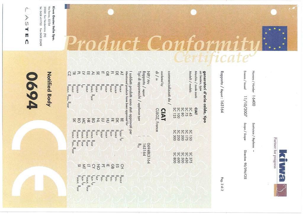
15 6. CERTIFICATION
16
17 Siège social Avenue Jean Falconnier B.P Culoz - France Tel. : +33 (0) Fax : +33 (0) info@ciat.fr - Compagnie Industrielle d Applications Thermiques S.A. au capital de R.C.S. Bourg-en-Bresse B CIAT Service Tel. : Fax : (0,15 / mn) Non contractual document. With the thought of material improvement always in mind, CIAT reserves the right,without notice, to proceed with any technical modification.
DRYPACK. Protecting installations Energy optimisation. Operating principle. Description. Biogas dehumidification system. Improved profitability.
 Protecting installations Energy optimisation Improved profitability Flow rate of conditioned biogas: up to 6 000 Nm 3 /h Biogas efficient waste recovery Operating principle When produced, biogas contains
CLIMACIAT AIR COMPACT
 Air handling units The modular and ultra-slim AHU to guarantee perfect solution Ideal for a compact installation Available in single-flow or aligned or adjacent dual-flow versions Air flow: up to 6 000
AQUACIAT. Water chillers. Free cooling modules for AQUACIAT2 700V to 1100V AQUACIAT POWER 1200V to 1800V USE RANGE FREE COOLING
 Free cooling modules for 2 700V to 1100V POWER 1200V to 1800V Cooling capacity: 185 to 485 kw Cooling only Hydraulic module Free cooling ENVIRONMENTALLY HFC R410A PROTECTION DE FRIENDLY L'ENVIRONNEMENT
Split inverter air-to-water heat pump CERTIFIED BY CERTITA. option 30/35-40/45
 Plug & Heat heat pump Quick and easy to install For new homes or boiler backup operation 50 HFC R410A CERTIFIED BY CERTITA Heating capacity: 5.5 to 22 kw option CERTIFIED BY CERTITA 30/35-40/45 USE The
GeoCIAT Modular. Components. Heat pump Heating only, Glycol/water mix/water. Refrigerant and hydraulic module diagram. HomeConnect control.
 Plug&Heat heat pump HomeConnect control For residential and tertiary applications Heating capacity (0/- C ): 5 to 9 kw Heating capacity (0/7 C ): 7 to kw Domestic 62 40A hot water Geo Cooling Modular Concept
Centrifugal air heaters hot water or electrical supply
 The economical solution with centralised production Individual adjustment in each room The most silent electric air heater to protect against frost or to heat large spaces A wide range of accessories Range:
MAGISTER. Compact and attractive design Energy savings with EC motor and self-regulating control. Easy to install. Use. Chilled water operation
 Extensive range of chilled water or direct expansion systems Compact and attractive design Energy savings with EC motor and self-regulating control Easy to install Cooling capacity: 10 to 116 k Air flow
VEXTRA. acoustic comfort Saves up to. 40% floor space. Use. Range. Description. Drycoolers. Slim design and. Capacity up to kw.
 Slim design and acoustic comfort Saves up to 40% floor space Capacity up to 50 kw Free cooling Water misting Use Drycoolers in this range are mainly designed for cooling water or glycol/water mix for:
FLOWAY. Floway Range. The dual-flow air handling unit with heat recovery guaranteeing an Economical and Durable solution. use.
 The dual-flow air handling unit with heat recovery guaranteeing an Economical and Durable solution use Air flow rate: 500 to 8500 m 3 /h is a PLUG & PLAY dual-flow ventilation unit equipped with a highly
AGEO CALEO. Water-to-water high temperature heat pumps USE RANGE DESCRIPTION. Designed to replace a conventional boiler and produce domestic hot water
 Designed to replace a conventional boiler and produce domestic hot water Heating capacity : 16 to 25 Heating Hydraulic module ENVIRONMENTALLY HFC R4A PROTECTION DE FRIENDLY L'ENVIRONNEMENT USE CIAT is
OPERA MORE. Use. Range. Drycoolers Air-cooled condensers. for LESS. Capacity: up to 1100 kw. Water misting. Free cooling
 MORE n More efficient n More flexible n More intelligent for LESS n Less energy n Less time n Less noise Capacity: up to 1100 kw 410A 407C 134a 404A Free cooling Water misting Use The range, available
CIATCOOLER LJA. Chilled water production units USE. Attractive design, Compact and quiet
 Attractive design, Compact and quiet Many customisable configurations possible For indoor installation New reliable technologies Version with Plug and Cool hydraulic module Cooling capacity: 23 to 140
EXPAIR. Use. Precision air handling cabinets. Reducted footprint Dual-wall construction
 Reducted footprint Dual-wall construction Built-in variable frequency drive PLC control Variable speed condenser fan Cooling capacity: 5 to 50 kw Air flow: 1 000 to 12 000 m 3 /h ErP READY Use Precision
HYDROCIAT LW R407C. Water cooled chillers USE RANGE
 Screw compressors CIAT dry direct expansion shell and tubes evaporator HPS equipment (High Power System) cooling or heating Heat recovery ENVIRONMENTALLY HFC R407C PROTECTION DE FRIENDLY L'ENVIRONNEMENT
WHE 2.24 / WHE 2.24 FF
 EN Wall-hung gas boilers WHE 2.24 WHE 2.24 FF User Guide 300011777-001-C . Contents 1 Introduction.............................................................................3 1.1 Symbols used...........................................................................................3
NA B AIR COMPACT. Instruction manual
 NA 08.41 B 09-2015 AIR COMPACT Instruction manual EN CONTENTS PAGE 1 - RECEIPT OF THE UNIT 2 1.1 Delivery/Reservations 2 1.2 Storage precautions 2 1.3 Packaging 2 1.4 Handling 2 2 - SAFETY INSTRUCTIONS
U tube models PTU 09, 12, 15, 25, 30, 35, 40, 45. single linear tube models PTS 09, 12, 15, 25, 30, 35, 40, 45
 U tube models PTU 09, 2, 5, 25, 30, 35, 40, 45 & single linear tube models PTS 09, 2, 5, 25, 30, 35, 40, 45 installation, servicing & operating instructions INSTALLATION, SERVICING AND OPERATING INSTRUCTIONS
Aquaciat Free cooling
 Aquaciat Free cooling NA 08.144 A 01-2009 Installation Operation Commissioning Maintenance CONTENTS PAGE Receiving the unit 2 Unloading 2 Think safety 2 Warranty 2 Storage 2 Installation 2 Hydraulic diagram
INSTALLATION AND MANINTENANCE INSTRUCTIONS
 INSTALLATION AND MANINTENANCE INSTRUCTIONS Appr. Nr. A 9503 T - 0085 AQ 0765 PEGASUS F2 T HIGH EFFICIENCY GAS-FIRED CAST-IRON BOILERS Models 51-68 - 85-102 2 Contents 1. General technical data 2. Dimensional
... LCSA - LCSBD - LCSC Gas Fired Unit Heaters ...
 LCSA - LCSBD - LCSC Gas Fired Unit Heaters LCSA complete with horizontal and optional vertical louvres LCSA - LCSBD - LCSC... Gas Fired Unit Heaters... The new LCSA builds on the technical excellence of
RIELLO 40 GS/M SERIES
 The Riello 40 GS/M series of two stage progressive or modulating gas burners, is a complete range of products developed to respond to any request of gas burners for hot air generator according to EN 1020.
V-Line. Nozzle-mix line burner
 V-Line Nozzle-mix line burner Duct Burners - V-Line 4-22.5-1 Nozzle-mixing line burner for use with low pressure natural gas, propane and butane. Suitable for operation in variable process air-flows. Stainless
ECOCIAT. Domestic hot water heat recovery unit. Use. Range
 Heat recovery unit Domestic hot water High energy efficiency with R410A Compact and quiet Scroll compressors Brazed-plate heat exchangers Heating Heat recovery ENVIRONMENTALLY FRIENDLY HFC R410A PROTECTION
Compact and silent Scroll compressors All-season operation
 Compact and silent Scroll compressors All-season operation Cooling capacity: 40 to 161 kw 410a Cooling only Use The new generation of CONDENCIAT condensation units is the solution for all split-system
BOILING PANS GAS & ELECTRICS
 PREMIUM BOILING PANS GAS & ELECTRICS MANUFACTURER'S INSTRUCTIONS Part A: Technical data Part B: Installation manual - WARNING - Installation and repairs must be carried out by personnel approved by the
GAS FR25 IR FRYERS. Grande Carte SPECIFICATIONS CONSTRUCTEUR. Part A: Technical characteristics Part B: Technical instructions for installation
 Grande Carte GAS FR25 IR FRYERS SPECIFICATIONS CONSTRUCTEUR Part A: Technical characteristics Part B: Technical instructions for installation - WARNING - Installation and repairs must be carried out by
Light oil - kerosene burner
 Installation, use and maintenance instructions Light oil - kerosene burner One stage operation CODE MODEL TYPE 374374 G3B 437T 90 (4) - 05/0 TECHNICAL FEATURES TYPE 437T Thermal power output 9 35 kw.6
Light oil burners. One stage operation
 Installation, use and maintenance instructions Light oil burners One stage operation CODE MODEL TYPE 3505 RDB CF 38 50 T3 350050 RDBR CF 6 50 TR 35050 RDBR CF 33 50 TR 35050 RDBR CF 38 50 T3R 350650 RDBR
ATMOSPHERIC GAS BOILER INSTALLATION, OPERATING AND MAINTENANCE MANUAL
 STREBEL GENEVA CE ATMOSPHERIC GAS BOILER INSTALLATION, OPERATING AND MAINTENANCE MANUAL INDEX TABLE 1 TECHNICAL DATA SECTION 1 SECTION 2 SECTION 3 SECTION 4 SECTION 5 SECTION 6 SECTION 7 SECTION 8 SECTION
Light oil / kerosene burner
 Installation, use and maintenance instructions Light oil / kerosene burner One stage operation CODE MODEL TYPE 374445 G5 444T50 290238 (5) - 05/20 TECHNICAL DATA Thermal power output 28 60 kw 2.3 5 kg/h
Technical information. Remeha P200. Pressurized boiler. Heat output: kw
 Technical information Remeha P200 R e m e h a P 2 0 0 Pressurized boiler Heat output: 59-256 kw Remeha P 200 CONTENTS Preface 3 1. Description of the unit 4 1.1 General 4 1.2 Burners 4 2. Construction
Remeha. Fuel oil/gas boilers P 520. Installation and Service Manual A
 Remeha Fuel oil/gas boilers EN Installation and Service Manual 300016859-001-A 63115 Declaration of conformity The appliance complies with the standard model described in declaration of compliance. It
SIME FORMAT WALL HUNG BOILERS MODEL 34i AND MODEL 34e. cod A
 cod. 6272262A GENERAL DATA Heating Data Heat Output Input (Adjustable) (Adjustable) Format 34i 11.2 34KW 45 145MJ/hr Format 34e 11.2 34KW 45 145MJ/hr General Specifications FORMAT 34i 34e Main burner injectors
VICTRIX 90 VICTRIX 115 Wall-hung condensing boilers for high power
 VICTRIX 90 VICTRIX 115 Wall-hung condensing boilers for high power VICTRIX 90 is the new wall-hung condensing boiler for room heating only, set-up for independent functioning and for that in cascade mode
PEGASUS F2 N 2S. CAST IRON GAS BOILER for heating with electronic ignition and flame control INSTRUCTIONS FOR USE, INSTALLATION AND MAINTENANCE
 PEGASUS F2 N 2S CAST IRON GAS BOILER for heating with electronic ignition and flame control INSTRUCTIONS FOR USE, INSTALLATION AND MAINTENANCE cod. 3544309/0 ediz. 01/2003 Carefully read the warnings in
Conversion Instructions Logano G234X. Gas boiler. Please read carefully before installing and servicing. Gas boiler
 Gas boiler UPON COMPLETION OF THE INSTALLATION THE INSTALLER MUST INSTRUCT THE OWNER AND OPERATOR ON THE FUNCTIONALITY AND THE PROPER OPERATION OF THE BOILER AND THE HEATING SYSTEM. INSTALLER MUST REVIEW
V3000 KNX. KNX PID control system on water GENERAL DESCRIPTION
 KNX PID control system on water Wall terminal with dial Wall terminal with display Radio-frequency remote control Available in the second quarter of 2008 Factory-recessed thermostat New-generation networked
INDITHERM. Low temperature gas burners
 INDITHERM Low temperature gas burners 1-2.3-1 High turndown for maximum operation flexibility. Maximum capacities up to 1800 kw. Designed for firing in indirect fired processes. Excellent combustion throughout
CLIMACIAT. air HanDLIng UnIT: CLIMaCIaT. Air handling unit
 AHU for all applications Designed to meet the EN 13053 and EN 1886 standards The effective solution for service sector, industry and healthcare applications air HanDLIng UnIT: CLIMaCIaT represents the
All Heaters Part L2B Compliant. Technical Data External Oil and Gas Cabinet Heaters. For Models. EVD Vertical Ducted EHD Hortizontal Ducted
 All Heaters Part L2B Compliant Technical Data External Oil and Gas Cabinet Heaters For Models EVD Vertical Ducted EHD Hortizontal Ducted Range & Configuration Vertical Forced Draught Oil and Gas 29 kw
IDE 20 / IDE 30 / IDE 50 IDE 60 / IDE 80
 IDE 20 / IDE 30 / IDE 50 IDE 60 / IDE 80 EN OPERATING MANUAL OIL HEATER TRT-BA-IDE20-30-50-60-80-TC-001-EN Table of contents Information on the use of this manual... 1 Scope of delivery... 1 General safety...
MHG201 Gas Hob Manual for Installation, Use and Maintenance
 MHG201 Gas Hob Manual for Installation, Use and Maintenance 1 Customer Care Department The Group Ltd. Harby Road Langar Nottinghamshire NG13 9HY T : 01949 862 012 F : 01949 862 003 E : customer.care@cda.eu
LOW NOx MODULATING GAS BURNERS
 RS/E - RS/EV BLU SERIES LOW NOx MODULATING GAS BURNERS RS/E - RS/EV BLU SERIES RS 300/E BLU 500/1350 3800 kw RS 400/E BLU 800/1800 4500 kw RS 300/EV BLU 500/1350 3800 kw RS 400/EV BLU 800/1800 4500 kw
"HC" AIRFLO. In-duct firing line burner
 "HC" AIRFLO In-duct firing line burner -.- High heat release up to.5 MW per unit of burner length (05 mm) Clean combustion with low CO and NO x emission levels Minimal process air pressure drops locally
DTG X.. N. Low temperature gas furnace. Instructions for use. English 14/11/2005
 DTG X.. N Low temperature gas furnace English 14/11/2005 Instructions for use Contents Important recommendations...................................................................3 1 Aeration.................................................................................................3
GAS FRYERS GRANDE CARTE MANUFACTURER S INSTRUCTIONS. Part A: Technical characteristics Part B: Installation instructions.
 GRANDE CARTE GAS FRYERS MANUFACTURER S INSTRUCTIONS Part A: Technical characteristics Part B: Installation instructions - WARNING - Installation and repairs must be carried out by personnel approved by
Heating, Air Conditioning, Ventilation. Отопление-Кондиционеры-Вентиляция. MTM 8-30 kw UNIVERSAL OIL HEATER OPERATING MANUAL
 Heating, Air Conditioning, Ventilation Отопление-Кондиционеры-Вентиляция MTM 8-30 kw UNIVERSAL OIL HEATER OPERATING MANUAL 1. Usage MTM 8-30 universal oil heater is designed for heating commercial rooms
Operating instructions
 Operating instructions Gas-fired condensing boiler Logano plus GB312 For the user Please read carefully before use 7 747 009 296-01/2007 EN Contents 1 For your safety..............................................
PICTOR DUAL CTN 24/RTN 24 CTFS 24/RTFS 24 CTFS 28/RTFS 28 INSTALLATION USE AND MAINTENANCE IST 04 C
 PICTOR CTN 24/RTN 24 CTFS 24/RTFS 24 CTFS 28/RTFS 28 DUAL GB INSTALLATION USE AND MAINTENANCE IST 04 C 161-02 Dear Customer, Thank you for choosing and buying one of our boilers. Please read these instructions
JUMBO INDIRECT FIRED DIESEL HEATER OPERATING INSTRUCTIONS
 JUMBO INDIRECT FIRED DIESEL HEATER OPERATING INSTRUCTIONS Before using the heater, read and understand all instructions and follow them carefully. The manufacturer is not responsible for damages to goods
BENSON LINEAR RADIANT TUBE
 BENSON LINEAR RADIANT TUBE Natural or Propane (Gas fired) I N S T A L L A T I O N C O M M I S S I O N I N G S E R V I C I N G U S E R I N S T R U C T I O N S September 2001 CONTENTS Page Compliance Notices
Series LV AIRFLO. In-duct firing line burner
 Series LV AIRFLO In-duct firing line burner Duct burners - LV AIRFLO 4-21.4-1 Series LV AIRFLO burners provide stable, efficient, raw gas operations in air streams with relatively low duct velocities.
DTG Eco / V130
 ECODENS Gas fired condensing boiler EN User Guide 300010111-001-B Contents 1 Introduction.............................................................................3 1.1 Symbols and abbreviations................................................................................3
... RHeco. High Efficiency Condensing Unit Heaters... Low NO x. ErP. ErP Lot 21 Seasonal Efficiency and NOx compliant
 ... RHeco... ErP 2021 ErP Lot 21 Seasonal Efficiency and NOx compliant RHeco...... Reznor continue their tradition of manufacturing high efficiency warm air heating equipment with the introduction of the
INSTALLATION, OPERATION AND MAINTENANCE. Ariterm Vedo
 INSTALLATION, OPERATION AND MAINTENANCE Ariterm Vedo CONTENTS General...3 Installation...4-5 Laddomat 21 Connection diagram...6 Temperature control valve...7 About burning wood...8 Operation...9-11 Service
ARIES DUAL MAINTENANCE MADE IN ITALY IST 04 C
 MADE IN ITALY ARIES DUAL Italian high quality GB IST 04 C 210-01 INSTALLA ATION USE AND MAINTENANCE Dear Customer, Thank you for choosing and buying one of our boilers. Please read these instructions carefully
HVG620 & HVG720 Gas Hob Manual for Installation, Use and Maintenance
 HVG620 & HVG720 Gas Hob Manual for Installation, Use and Maintenance Customer Care Department The Group Ltd. Harby Road Langar Nottinghamshire NG13 9HY T : 01949 862 012 F : 01949 862 003 E : customer
HIGH POWER. VICTRIX PRO 2 ErP. High power, wall-hung condensation boiler
 HIGH POWER VICTRIX PRO 2 ErP High power, wall-hung condensation boiler MAIN INDEX INDEX 1 VICTRIX PRO 35-55 2 ErP SPECIFICATIONS...5 2 VICTRIX PRO 80-100-120 2 ErP SPECIFICATIONS...6 3 VICTRIX PRO 35-55
HG 675 CX 60 HG 675 CN 60 HG 675 CW 60
 HG 675 X 60 HG 675 CX 60 HG 675 CN 60 HG 675 CW 60 1 2 1. : 93/68: 90/396: 2006/95/CE: 2004/108/CE: - 1935/2004:. 2002/95/CE: RoHS 2.,.,,,,...,. (,..)..,,.,. ( ),,, ;,,.,.....,.,,,,,,...,. (..),,.,..,.,,,,
MAX O GAZ. Condensing water heater TECHNICAL MANUAL
 MAX O GAZ Condensing water heater TECHNICAL MANUAL 2 CONTENTS THE COMPONENTS OF THE MAX O GAZ.. 1 4 BALANCED FLUE AND CONVENTIONAL FLUE MAX O GAZ FEATURES. 3 6 INSTALLATION OF THE MAX O GAZ... 5 8 STANDARD
SAMPLE SPECIFICATION FOR RIELLO ARRAY MODULATING BOILER
 SAMPLE SPECIFICATION FOR RIELLO ARRAY MODULATING BOILER PART 1 GENERAL 1.01 RELATED DOCUMENTS A. ANSI Z21.13 American National Standard for Gas-Fired Low Pressure Steam and Hot Water Boilers B. ASME Section
PREEVA air handling unit
 APPICATINS Heating, ventilation, cooling, heat recovery >> FACTRIES >> commercial premises >> WAREHUSES >> HAS >> SPRTS & EISURE >> PACES F WRSHIP >> RESTAURANTS PREEVA air handling unit www.reznor.eu
Euron. Compact Wall Mounted Gas Fired Condensing Boilers and Combis with Outputs 24kW - 30kW BOILERS
 Euron Compact Wall Mounted as Fired Condensing Boilers and Combis with Outputs 24kW - 30kW BOILERS Compact, Efficient & Easy to Install & Maintain The Euron range of wall mounted gas fired condensing boilers
CI/SfB X. EnviroPak Series GAS FIRED HEATING, VENTILATION AND COOLING UNITS
 CI/SfB 56.83 X EnviroPak Series GAS FIRED HEATING, VENTIATIN AND CING UNITS EnviroPak Series GAS FIRED HEATING, VENTIATIN AND CING UNITS Introduction The Reznor EnviroPak is a new generation of gas fired
RMG IT ES PT GB FR BE
 RMG IT ES PT GB FR BE INSTALLER INSTRUCTIONS ENGLISH CONTENTS 1 DESCRIPTION OF THE BOILER........................................................................ pag. 38 2 INSTALLATION.......................................................................................
R e m e h a P Technical Information. Remeha P 300. Pressurized boiler. Heat output: kw
 Technical Information Remeha P 300 R e m e h a P 3 0 0 Pressurized boiler Heat output: 278-709 kw Remeha P 300 CONTENTS Preface 3 1 Description of the unit 3 1.1 General 3 1.2 Burners 3 2 Construction
VPC Gas Cabinet Heater Range
 VPC Gas Cabinet Heater Range Industrial & Commercial Heating Systems. www.powrmatic.co.uk HEATING // VENTIATION // AIR CONDITIONING // OEM PRODUCTS VPC Overview Models Available VPC UF - Upright Freeblowing
Contents. 1. Instructions for safe and proper use Positioning of hob Attachment to support structure Electrical connection 22
 Contents 1. Instructions for safe and proper use 19 2. Positioning of hob 20 2.1 Attachment to support structure 20 3. Electrical connection 22 4. Gas connection 23 4.1 Connection to LPG 24 4.2 Ventilation
Stainless steel range of condensing boilers. Designed to meet carbon reduction targets. Lifetime service and support. Outputs from 50kW to 660kW
 Stainless steel range of condensing boilers Outputs from 50kW to 660kW Designed to meet carbon reduction targets Lifetime service and support Totally dependable. page 1 www.pottertoncommercial.co.uk Contents
Alpha CombiMax 350 and 600
 Installation and Servicing Instructions Alpha CombiMax 350 and 600 Unvented Hot Water Store for use with the Alpha 240/280 Range of Gas Fired Combination Boilers For Technical help or for Service call...
Aluminium range of condensing boilers. Works every time. Designed to meet carbon reduction targets. Lifetime service and support
 Aluminium range of condensing boilers Outputs from 30kW to 600kW Designed to meet carbon reduction targets Lifetime service and support Works every time. www.pottertoncommercial.co.uk Aluminium range of
SURE HEAT MANUFACTURING
 SURE HEAT MANUFACTURING Installation and Operating Instructions for NATURAL & L.P. GAS A.G.A. SINGLE & DUAL BURNER VENTED UNITS Model: RP (8,24,30)-N GO (8,24,30)-N GLO (8,24,30)-N WO (8,24,30)-N CO (8,24,30)-N
INSTALLATION AND OPERATING INSTRUCTIONS AVANTTIA
 INSTALLATION AND OPERATING INSTRUCTIONS AVANTTIA CGM-04/392 ER-0170/1996 Thank you for choosing a DOMUSA TEKNIK heating boiler. From the range of DOMUSA TEKNIK products you have chosen the Avanttia model.
TWO STAGE HEAVY OIL BURNERS
 TWO STAGE HEAVY OIL BURNERS PRESS N SERIES PRESS 30 N 85/171 342 kw PRESS 45 N 114/205 513 kw PRESS 60 N 171/342 684 kw PRESS 100 N 285/490 1140 kw The PRESS N series of burners covers a firing range from
Gas Instantaneous Water Heater
 6 720 607 823 GB (06.06) SM Installation and Operating Instructions Gas Instantaneous Water Heater WR10..B... WR11..B... With electronic ignition and triple safety system consisting of ionisation detector,
Superior. A Compact Floor Standing Gas Fired, High Efficiency Condensing Hot Water Boiler. Outputs 120, 160, 200, 240, 280 kw
 Superior A Compact Floor Standing Gas Fired, High Efficiency Condensing Hot Water Boiler Outputs 120, 160, 200, 240, 280 kw 1 The Superior is a, pre-assembled floor standing, gas fired high efficiency
CLIMACIAT AIRTOP. Air handling units. Very short delivery time Double wall with 50 mm insulation. Complete range meeting all the tertiary requirements
 Excellent quality / price ratio Very short delivery time Double wall 50 mm insulation Complete range meeting all the tertiary requirements Air flow : 000 to 7 000 m 3 /h DESCRIPTION Casing Double wall
24-28 kw Conventional Combi Gas Boiler. Lawa / LawaPlus
 24-28 kw Conventional Combi Gas Boiler Lawa / LawaPlus Conventional Combi Gas Boilers Warmhaus wall-hung gas combi boilers Lawa and LawaPlus, with the advantage of its width as 288mm, are easily fit to
TEMPRA. Wall Mounted Fan Flue System boiler. Wall mounted fanned flue boiler INSTALLATION AND USE INSTRUCTIONS. Appr. nr. B A - CE 0063 AQ 2150
 Wall Mounted Fan Flue System boiler Appr. nr. B 94.04 A - CE 0063 AQ 2150 Phone numbers: Installer Service Engineer Serial N Wall mounted fanned flue boiler INSTALLATION AND USE INSTRUCTIONS Please read
CI/SfB X. RHeco Series CONDENSING GAS FIRED UNIT HEATERS
 CI/SfB 56.83 X RHeco Series CONDENSING GAS FIRED UNIT HEATERS RHeco Series CONDENSING GAS FIRED UNIT HEATERS Introduction Features & Benefits Model Range Reznor continue their tradition of manufacturing
User Manual. 600mm, 700mm & 900mm Gas Cooktops Model No. CF6GS, CF6GW, CF7GS, CF9GS
 User Manual 600mm, 700mm & 900mm Gas Cooktops Model No. CF6GS, CF6GW, CF7GS, CF9GS For all product enquires, including warranty support, please contact our Customer Care team 1800 444 357 or email customercare@hapl.com.au
INDITHERM. Low temperature gas burners
 INDITHERM Low temperature gas burners 1-2.3-1 High turndown for maximum operation flexibility. Maximum capacities up to 1800 kw. Designed for firing in indirect fired processes. Excellent combustion throughout
... UDSA - UDSBD Gas fired unit heaters...
 UDSA - UDSBD Gas fired unit heaters UDSA with axial fan Reznor V3 unit heaters are one of the most technically advanced products available on the market today. Incorporating a radical new horizontal heat
PDG PDG4.1...A PDG5.0...A INSTRUCTION MANUAL IO 00450/2 ( )
") PDG4.0... PDG4.1...A PDG5.0...A INSTRUCTION MANUAL IO 00450/2 (11.2010) DEAR CUSTOMER, Outstanding user-friendliness and excellent efficiency make cooktops a perfect choice. Please read this manual thoroughly
PDG4.0... PDG4.1...A PDG5.0...A INSTRUCTION MANUAL IO 00450/2 (11.2010) DEAR CUSTOMER, Outstanding user-friendliness and excellent efficiency make cooktops a perfect choice. Please read this manual thoroughly
BENSON.... Variante3 Fired Unit Heaters...
 NSON Variante3 as ired Unit Heaters 3 Variante... as ired Unit Heaters... The new Variante3 builds on the technical excellence of the previous range to provide cost effective and robust heating for industrial
GAS SERIES HOT AIR GENERATORS (FLOOR) HANDBOOK MODELS : GAS 20 GAS 25 GAS 29 GAS 40
 HANDBOOK MODELS : GAS 20 GAS 25 GAS 29 GAS 40") HEAD OFFICE : VIA BIBAN 56 ( Z.I. ) 31030 CARBONERA TREVISO - ITALIA TEL. ++39 0422 445363 FAX ++39 0422 398646 EMAIL = info@bpstecnologie.com 1312 GAS SERIES HOT AIR GENERATORS (FLOOR) HANDBOOK MODELS
HEAD OFFICE : VIA BIBAN 56 ( Z.I. ) 31030 CARBONERA TREVISO - ITALIA TEL. ++39 0422 445363 FAX ++39 0422 398646 EMAIL = info@bpstecnologie.com 1312 GAS SERIES HOT AIR GENERATORS (FLOOR) HANDBOOK MODELS
installation & operating instructions
 installation & operating instructions RGE 410 RA/RM-2D 822706106 MO-M 0740 INTRODUCTION We are pleased that you have chosen this refrigerator and hope you will derive much satisfaction from using it.
IST 03 C ELBA DUAL INSTALLATION, USE AND MAINTENANCE
 IST 03 C 202-01 ELBA DUAL INSTALLATION, USE AND MAINTENANCE GB Thank you for choosing our boilers. Please read these installation and maintenance instructions with care. Please note that the boiler must
VPC Gas Cabinet Heater Range Architects of your environment. heating ventilation air conditioning
 VPC Gas Cabinet Heater Range Architects of your environment heating ventilation air conditioning 1 Product Overview Benefits Installer Friendly ow evel Flue Discharge Option (No Roof Work) Room Sealed
DYNACIAT ILG. Use. Description. Heat pumps
 High energy efficiency Compact and quiet Scroll compressors Brazed-plate heat exchangers Self-adjusting electronic control Hydraulic module linked with aquatherm module Cooling capacity: 30 to 80 kw Heating
SolarWall Fan Units. Introduction. Features. By Conserval Engineering Inc.
 SolarWall Fan Units Introduction The SolarWall fan units are designed to be used maximize the supply of solar heated air into the building via fabric ducting. The units are complete with modulating dampers
Wall-hung gas boilers. Instructions for use. English 31/08/05
 City 1.24/II Chimney and VMC - City 1.24/II FF City 2.24/II Chimney and VMC - City 2.24/II FF - City 2.28 FF City 3.24/II Chimney - City 3.24/II FF City 24 BIC/II - City 24 BIC/II FF City Condens 1.24,
Read installation manual prior to installation of this unit! Read user manual before putting this unit in operation!
 Gas Instantaneous Water Heater WR 11/14/18.G... Installation Manual and Operating Instructions ZA Read installation manual prior to installation of this unit! Read user manual before putting this unit
PREEVA EC Gas Fired Heating, Ventilation & Cooling Units
 ... PREEVA EC Gas Fired Heating, Ventilation & Cooling Units... ErP 2018 ErP Lot 21 Seasonal Efficiency and Nx compliant ErP 2018 ErP Lot 21 Seasonal Efficiency and Nx compliant PREEVA EC... Gas Fired
CP+ Gas & Oil Cabinet Heater Range
 CP+ Gas & Oil Cabinet Heater Range Industrial & Commercial Heating Systems. www.powrmatic.co.uk CP+ CP+EA External Heater HEATING // VENTILATION // AIR CONDITIONING // OEM PRODUCTS CP+ Overview Designed
GAS & ELECTRIC FRYERS
 OPTIMUM 700 & 900 GAS & ELECTRIC FRYERS BUILDER S SPECIFICATIONS Part A: Technical characteristics Part B: Technical instructions for the installer - WARNING - Installation and repairs must be carried
ELECTRIC PASTA COOKERS
 OPTIMUM 700 & 900 ELECTRIC PASTA COOKERS BUILDER S SPECIFICATIONS Part A: Technical characteristics Part B: Technical instructions for the installer - WARNING - Installation and repairs must be carried
USER MANUAL 9kW LILLY PELLET STOVE
 USER MANUAL 9kW LILLY PELLET STOVE Table of Contents.Overview of Stove Parts... 2.Technical Characteristics... 3 3.Important Information... 4 4.Pellet Specification...5 5.Technology... 6 6.Installation...
TC MODULE (FFD) (with Gas Hob)
 (with Gas Hob)") TC MODULE (FFD) (with Gas Hob) Installation Instructions REMEMBER: when replacing a part on this appliance, use only spare parts that you can be assured conform to the safety and performance specification
TC MODULE (FFD) (with Gas Hob) Installation Instructions REMEMBER: when replacing a part on this appliance, use only spare parts that you can be assured conform to the safety and performance specification