Bravo. Troubleshooting Guide
|
|
|
- Marcus Sutton
- 6 years ago
- Views:
Transcription
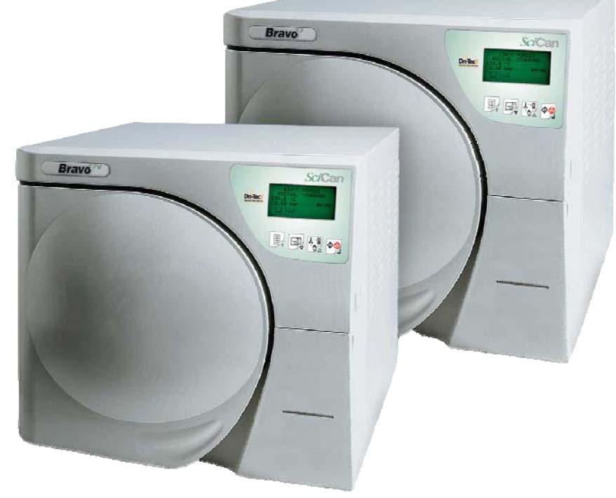
1 Bravo Troubleshooting Guide
2 Table of Contents Table of Contents 2 Bravo Alarm Code by Alarm Code Indication 3 Alarm Codes A022, A023, A024, E020 & E021 Door Locking Problems 4-9 Alarm Code E Alarm Code E020 & E Alarm Code A032 Leveler Problem 13 Alarm Code A040 & E041 Automatic Water Filling Problem Alarm Codes A101, A102, A103 & A104 PTX Broken 18 Alarm Codes A111, A112, A113 & A114 PTX Short-circuit 19 Alarm Code A200 Heating Problem 20 Alarm Code A250 PV1 Timeout 21 Alarm Code A251 ATM1 Timeout 22 Alarm Code A252 PP1 Timeout 23 Alarm Code A253 PV2 Timeout 24 Alarm Code A254 ATM2 Timeout 25 Alarm Code A255 PP2 Timeout 26 Alarm Code A256 PV3 Timeout 27 Alarm Code A257 ATM3 Timeout 28 Alarm Code A258 PPP Timeout 29 Alarm Code A259 Process Timeout 30 Alarm Code A260 PPD Timeout 31 Alarm Code E000 Black-Out Bravo Fuses 34 Alarm Code E030 Manual Filling Water Level Minimum 35 Alarm Code E031 Exhaust Level Max 36 Alarm Codes E900, E901 & E902 Vacuum Test Failed 37 Alarm Code E999 Manual Cycle Interruption 38 Alarm Codes H150 MPX Broken & H160 MPX Short-circuit 39 Alarm Code H400 P/T Problem, H401 T/P Problem & H402 Temperature Over Limit 40 Alarm Codes H403 Temperature Under Limit, H404 PT1 Fluctuating & H405 P Over Limit 41 Alarm Code H406 P Under Limit & H410 Timer Problem 42 Alarm Codes H990 Over Pressure, H991 Overheating PT1, H992 Overheating PT2 & H993 Overheating PT3 43 Bravo Forced Ventilation 44 Bravo Vacuum Timeouts or Will Not Vent A250, A253, A256 & A260 Troubleshooting 45 Bravo 17 Vacuum Pump H5P5 Rebuild Instructions Bravo 17V & 21V Vacuum Pump EVO10 Rebuild Instructions Bravo Chamber Will Not Pressurize A251, A252, A254, A255, A257, A258 & A Bravo Door Gasket Replacement 64 Bravo Door Plate Adjustment 65 Bravo Entering Setup Mode & Disabling Password 66 Bravo Drying Time Adjustment Bravo Continuous Cycles Bravo Maintenance & Display Warning Messages Bravo Distilled Water Reservoir Drain Kit Installation Instructions Bravo Upgrade Kit Installation Instructions Bravo Valves & Component Resistance Readings 86 2
3 Bravo Alarm Code by Alarm Indication Alarm Indication Code Alarm Description ATM1 Timeout A251 1 st rise to ambient pressure not reached within timeout ATM2 Timeout A254 2nd rise to ambient pressure not reached within timeout ATM3 Timeout A257 3rd rise to ambient pressure not reached within timeout Black-Out E000 Blackout (loss of power) Door Locked E021 Exceeded timeout for activating door locking system (opening) Door Open E010 Door open Door Unlocked E020 Exceeded timeout for activating door locking system (closing) Exhaust Max E031 Water in the drain tank at maximum (Max) level Filling Problem A040 Failure to fill the clear water tank (automatic filling) Filling Problem E041 Filling the tank to frequently or external water source out of water (automatic filling) Heating Problem A200 Pre-heating not performed within the timeout (sterilization chamber heating problem) Level Problem A032 Sensor-level problem Locking Problem A022 System door lock microswitches failed (Off-Off) Locking Problem A023 System door lock microswitches failed (On-On) Locking Problem A024 System door lock microswitches failed (On-Off) Manual Stop E999 Manual cycle interruption MPX Broken H150 MPX pressure sensor broken MPX Shout Circuit H160 MPX pressure sensor short-circuited/not connected Overheating PT1 H991 Overheating (sterilization chamber PT1) Overheating PT2 H992 Overheating (steam generator PT2) Overheating PT3 H993 Overheating (band heating element PT3) Overpressure H990 Excessive pressure (sterilization chamber, MPX) P Over Limit H405 Pressure above Max limit (Phase Process) P Under Limit H406 Pressure below Min limit (Phase Process) PPD Timeout A260 Chamber depressurization not completed within timeout PPP Timeout A258 3 rd pressure pulse not reached within timeout Process Timeout A259 Phase of Process not started within timeout P/T Problem H400 Ratio Pconv/T not balanced (Pconv>T) (Phase Process) PT1 Broken A101 PT1 broken (sterilization chamber) PT1 Fluctuating H404 Temperature fluctuating over the limit (Phase Process) PT2 Broken A102 PT2 broken (steam generator) PT3 Broken A103 PT3 broken (sterilization chamber heating element) PT4 Broken A104 PT4 broken (sterilization chamber wall) PT1 Short Circuit A111 PT1 short-circuited (sterilization chamber) PT2 Short Circuit A112 PT2 short-circuited (steam generator) PT3 Short Circuit A113 PT3 short-circuited (sterilization chamber heating element) PT4 Short Circuit A114 PT4 short-circuited (sterilization chamber wall) PV1 Timeout A250 1 st vacuum pulse not reached within timeout PP1 Timeout A252 1 st pressure pulse not reached within timeout PV2 Timeout A253 2 nd vacuum pulse not reached within timeout PP2 Timeout A255 2 nd pressure pulse not reached within timeout PV3 Timeout A256 3 rd vacuum pulse not reached within timeout Test Failed E900 Vacuum Test failed (during the leakage phase) Test Failed E901 Vacuum Test failed (during the waiting phase) Test Failed E902 Vacuum Test failed (vacuum pulse timeout exceeded) Timer Problem H410 Wrong maintenance time (Phase Process) T Over Limit H402 Temperature above Max limit (Phase Process) T/P Problem H401 Ratio T/Pconv not balanced (T>Pconv ) (Phase Process) T Under Limit H403 Temperature below Min limit (Phase Process) Water Min E030 Water in the fill tank at minimum (Min) level 3
4 Door Locking Error Codes A022, A023, A024, E020 & E021 When the door motor is in the open position the lower micro switch is activated and should read open and the roller micro switch is deactivated and should read closed. Bravo Error A022 Locking Problem (Both door motor switches activated) Failure of the micro switches (OFF-OFF), during the initial self test the two micro switches are ON. Reset door motor and test door motor. Check fuse F4 (1.25A 250V) on Gam PCB. Check door micro switches and wiring. Reset red button on Troll PCB Bravo Error A023 Locking Problem (Door motor between switches, neither switch is activated) Failure of the micro switches (ON-ON), during the initial self test the two micro switches are OFF. Blackout during opening Reset door motor and test door motor. Check fuse F4 (1.25A 250V) on Gam PCB. Check door micro switches and wiring. Reset red button on Troll PCB Bravo Error A024 Locking Problem (Door in closed position) Failure of micro switches (ON-OFF), during the initial self test the closing micro switch is ON and the opening micro switch is OFF. Sterilizer turned OFF before completing the safety procedure. Reset door motor and test door motor. Check fuse F4 (1.25A 20V) on Gam PCB. Check door micro switches and wiring. Reset red button on Troll PCB Bravo Error E020 Door Unlocked When a cycle was started the door exceeded the timeout for the operation of the door locking mechanism (closing) 2.5 seconds. Go to the Service menu (service code ), device test, manual, locking device. Select the locking device then activate the door motor and check if the door hook is closing and opening. If the door motor does not operate check fuse F4 on the Bravo Gam PCB and check the red reset button on the Troll PCB. Check the Pressure Switch you should have continuity between the two white wires. 4
, device test, manual, locking device. Select the locking device then activate the door motor and check if the door hook is closing and opening.")

5 Bravo Error E021 Door Locked At the end of the cycle the door exceeded the timeout for the operation of the door locking mechanism (opening) 2.5 seconds. Go to the Service menu (service code ), device test, manual, locking device. Select the locking device then activate the door motor and check if the door hook is closing and opening. If the door motor does not operate check fuse F4 on the Bravo Gam PCB and check the red reset button on the Troll PCB. Check the Pressure Switch you should have continuity between the two white wires. GAM PCB Troll PCB Fuse F4 Red Reset Button Pressure Switch Bravo Door Switches Hook Micro switch # Door Micro switch # Hook Micro switch # Door Approach Micro switch is a normally open switch. Hook Micro switches are normally closed switches. 5


6 Bravo Door Switches Electrical Connections Normally Open GAM Board Normally Closed Troll Board Normally Open Normally Closed Normally Closed Normally Closed Black Blue White Brown Red Blue Black White Brown Red Bravo Door Motor Reset for Gam PCB Remove the cover, and then remove jumper X21 located above the battery. X21 Jumper Push and hold the hidden key while turning the power ON. The message Locking Device will appear on the LCD. Release the hidden key and press the stop/start key to reset the door locking mechanism. Open the door and press the arrow up key to exit. Turn the Bravo OFF and reinstall X21. Hidden Key Stop/Start Key Arrow Up Key 6


7 Bravo Door Motor Reset for Troll PCB The cover does not need to be removed. Push and hold the hidden key while turning the power ON. The message Locking Device will appear on the LCD. Release the hidden key and press the stop/start key to reset the door locking mechanism. Open the door and press the arrow up key to exit. If the door overload function has been triggered, there is no more beeping sound when pressing the keypad remove the cover and reset the red button on the PCB. Hidden Key Hidden Key Stop/Start Key Arrow Up Key Bravo Door Motor Troubleshooting The Bravo Door Motor is a DC motor. The voltage to the motor should read VDC. If replacing the door motor the white wire must be connected to the terminal with the red or blue dot to the left of the label. Red Dot or Blue Dot If there is no voltage to the door motor bypass the pressure switch. Remove the two white wires and connect them together. If you now have voltage to the door motor the pressure switch is defective. 7


8 Bravo Door Micro switch Wiring Troll PCB Door Closed Hook Micro switch Door Open Micro switch Blue & Black wires to Door Closed Micro switch Door Open Hook Micro switch White wire common to open & closed Door Hook Micro switches. Brown wire goes to door open Hook Micro switch Red wire goes to door closed Hook Micro switch Bravo Door Motor Wiring Troll PCB Door Motor reads approx. 120 Ω White wire to pressure switch Black wire to door motor 8
9 Bravo Door Motor Hook & Switch Assembly Item # Description Part # Comments 1 Door Roller Switch The roller switch has normally closed contacts that will open when the switch is activated. 2 Door Closing Hook (upper hook) C0BP This hook (upper) locks the door closed and activates the door roller switch when the door motor is in the closed position. 3 Door Closing Hook (lower hook) C0BP This hook (lower) locks the door closed and activates the door open hook switch when the door motor is in the open position. 4 Door Switch The door switch has normally open contacts and will close when the door is manually pushed closed. 5 Door Position Pin K0 When manually closing door if door does not stay closed or is too hard to close check door position adjustment. 6 Door Motor Shaft Top of door motor shaft. If door motor will not function (no power) and door must be opened try turning the shaft counterclockwise using a large screwdriver. 7 Door Hook Switch Open The door hook switch open has normally closed contacts that will open when the switch is activated. 9


10 Bravo Error E010 Door Open When a cycle is started the door must be closed and the flashing key icon should appear on the display. If no flashing key icon appears check the Door Microswitch, it is normally open and should be closed when the door is closed. Manually activate the switch and see if it closes. If door switch closes when manually activated but not when door is closed check that the switch is firmly attached to the mounting plate and has not come loose. Adjust door switch actuator. To access the door switch actuator adjustment, remove the 5 screws securing the door facia to the door and remove the door facia. Loosen the door switch actuator locking nut and adjust actuator using a 3mm Allen wrench. If the door switch actuates when the door is closed but the door is pushed back open when the door motor closes adjust the actuator out so the door must close further for the door switch to close. 5 Door Facia Screws Door Switch Actuator Adjustment Door Switch Actuator Door Microswitch Part #
11 Bravo Error E020 Door Unlocked When a cycle was started the door exceeded the timeout for the operation of the door locking mechanism (closing) 2.5 seconds. Go to the Service menu (service code ), device test, manual, locking device. Select the locking device then activate the door motor and check if the door hook is closing and opening. If the door motor does not operate check fuse F4 on the Bravo Gam PCB and check the red reset button on the Troll PCB. Check the Pressure Switch you should have continuity between the two white wires. Bravo Error E021 Door Locked At the end of the cycle the door exceeded the timeout for the operation of the door locking mechanism (opening) 2.5 seconds. Go to the Service menu (service code ), device test, manual, locking device. Select the locking device then activate the door motor and check if the door hook is closing and opening. If the door motor does not operate check fuse F4 on the Bravo Gam PCB and check the red reset button on the Troll PCB. Check the Pressure Switch you should have continuity between the two white wires. GAM PCB Fuse F4 Troll PCB Red Reset Button Pressure Switch 11
, loosen the nut (1) and turn the positioner (2) clockwise. 4.")
12 Bravo Door Positioner Adjustment 1. Remove the covers (left, upper & right). 2. Open and close the door to check its operation. 3. In case the door does not remain closed (no click at the stroke end), loosen the nut (1) and turn the positioner (2) clockwise. 4. In case of resistance on closing/opening the door, loosen the nut and turn the positioner counterclockwise. 5. Tighten the nut. 6. Perform a sterilization cycle. 12


13 Bravo Error A032 Level Problem Error A032 Level Problem Problem with the water level floats. Lighting of both Min & Max level LED s Check the float switch wiring and plugs. Check the floats. Check that Bravo is not plugged into a plug strip. Check receptacle with a ground tester plug. The Bravo sterilizers have three float switches. Two of them are located in the clean water reservoir and one is located in the used water reservoir. The switches in the clean water reservoir are visible from the front of the Bravo and the used water reservoir switch from the rear of the Bravo. Clean Water Level Sensor Min Part # Used Water Level Sensor Max Part # Clean Water Level Sensor Max Part # The used water reservoir float is wire number 1 and connects to terminal SS+ on the PCB. It is a normally closed switch. The clean water reservoir MIN float is wire number 2 and connects to terminal SC on the PCB. It is a normally open switch. The clean water reservoir MAX float is wire number 3 and connects to terminal SC+ on the PCB. It is a normally closed switch. PCB terminals SS+, SC & SC+ are located on the top left side of the PCB. 13

14 Bravo Error A040 & E041 Filling Problem Alarm Error A040 Filling Problem Alarm Failure to automatically fill the Bravo sterilizer from the external water tank, the MIN level signaling is not turned OFF within 2 minutes from the start command of the automatic filling. Note: If Bravo is a new installation or was completely drained you may need to turn the Bravo OFF and back ON to allow the unit to automatically fill twice to get sufficient water to activate the MIN level switch. 1. Check for water in the external filling tank. 2. Check for a kinked tubing from the external filling tank to the Bravo sterilizer. 3. Check that the valve on the external filling tank is open. 4. Check water filter is not clogged or cracked. If the water filter is cracked the pump may be louder than normal when running. 5. Check the auxiliary pump is providing water to the reservoir. Pump is located in rear of Bravo mounted vertically. 6. Prime Auxiliary Water Pump 7. Disassemble and clean Auxiliary Pump Error E041 Filling Problem In automatic fill mode unit is filling too frequently. Two automatic fills every two cycles. 1. Check automatic fill bottle for water. 2. Check tubing from automatic fill bottle to back of unit for kinks. 3. Check water filter on input of Auxiliary Pump. 4. Check Auxiliary Pump. Auxiliary Pump Priming Procedure 1/4" Tubing Basting Syringe 14


15 When error code A040 appears the auxiliary pump is not pulling water into the clean water reservoir. To prime the auxiliary pump turn the unit OFF. Go to the rear of the Bravo and remove the tube coming from the external clean water reservoir. Connect a short piece of 1/4" tubing to the auxiliary pump inlet elbow. Auxiliary Pump Inlet Elbow Fill a syringe with water and connect the syringe to the 1/4" tubing. Turn the Bravo on and when the check-up is complete enter the Setup Mode. Entering Setup Mode To enter the setup mode press and hold the first key on the left for several seconds until the display shows Bravo Setup. If the display asks for a password, see instructions to disable password. Press the first key on the right to continue. 15
16 Press the second key on the left to select Service. Press the first key on the right to continue. A service code is required to enter the Service Menu. Press press the first key on the right to continue. - Key + Key Device Test will appear on the top line of the display. Press the first key on the right to continue. Automatic Test will appear on the top line of the display. Press the second key on the left Test. Press the first key on the right to continue. to select Manual Locking Device will appear on the top line of the display. Press the second key on the left to select the Auxiliary Pump. Press the first key on the right to continue. Press and hold the first key on the right while pressing the plunger on the syringe connected to the rear of the Bravo. If the syringe runs out of water release the first key on the right and refill the syringe. When the pump is operating properly the syringe plunger will move into the syringe on its own or with very little pressure. Reconnect the automatic fill bottle and hold in the first key on the right and verify that water is entering the Bravo from the bottle. To exit setup press and release the first key on the left repeatedly until the display shows Exit Setup or Setup Completely. Press the first key on the right to return to the Standby screen. 16


17 Bravo Water Pump disassembly for cleaning and inspection Remove wires from pump and solenoid coils. Remove pump inlet and outlet tubing. Remove two screws that hold shaft to pump coil. Hold white shaft with one hand and white mounting piece with screws with the other hand. Push pump white shaft in slightly and turn counterclockwise. Carefully disassemble pump. Reverse procedure to reassemble. 17
18 Bravo Error A101, A102, A103 & A104 PTX Broken Error A101 PT1 Broken (Chamber Thermocouple) The temperature detected by PT1 is higher than 250 C. 1. PT1 is broken should read approximately 1056Ω connected and 1086Ω disconnected. 2. Check the temperature value on the display. Error A102 PT2 Broken (Steam Generator Thermocouple) The temperature detected by PT2 is higher than 250 C PT2 is broken should read approximately 1056Ω connected and 1086Ω disconnected. Check water pump not feeding water to steam generator. Steam Generator clogged. Check PT2 temperature by holding in hidden key after unit is turned ON. Error A103 PT3 Broken (Chamber Heating Thermocouple) The temperature detected by PT3 is higher than 250 C. 1. PT3 is broken should read approximately 1056Ω connected and 1086Ω disconnected. 2. Check the PT3 temperature by holding in hidden key after unit is turned ON. Error A104 PT4 Broken (Chamber Wall Thermocouple) The temperature detected by PT4 is higher than 250 C. 1. PT4 is broken should read approximately 1056Ω connected and 1086Ω disconnected. 2. Check the PT4 temperature by holding in hidden key after unit is turned ON. Hidden Key 18
19 Bravo Error A111, A112, A113 & A114 PTX Short-circuit Error A111 PT1 Short-circuit (Chamber Thermocouple) Short-circuit in the PT1 probe. PT1 is reading a temperature value lower than 1 C. 1. Check the temperature value on the display. 2. If just being installed make sure unit was not in a cold truck overnight. 3. PT1 is short-circuited should read approximately 1056Ω connected and 1086Ω disconnected. Error A112 PT2 Short-circuit (Steam Generator Thermocouple) Short-circuit in the PT2 probe. PT2 is reading a temperature value lower than 1 C. 1. Check PT2 temperature by holding in hidden key after unit is turned ON. 2. If just being installed make sure unit was not in a cold truck overnight. 3. PT2 is short-circuited should read approximately 1056Ω connected and 1086Ω disconnected. Error A113 PT3 Short-circuit (Chamber Heating Thermocouple) Short-circuit in the PT3 probe. PT3 is reading a temperature value lower than 1 C. 1. Check PT3 temperature by holding in hidden key after unit is turned ON. 2. If just being installed make sure unit was not in a cold truck overnight. 3. PT3 is short-circuited should read approximately 1056Ω connected and 1086Ω disconnected. Error A114 PT4 Broken (Chamber Wall Thermocouple) Short-circuit in the PT4 probe. PT4 is reading a temperature value lower than 1 C. 1. Check PT4 temperature by holding in hidden key after unit is turned ON. 2. If just being installed make sure unit was not in a cold truck overnight. 3. PT4 is short-circuited should read approximately 1056Ω connected and 1086Ω disconnected. Hidden Key 19


20 Troubleshooting Bravo Error A200 Error A200 Heating Problem Preheating phase not performed within the preset time. Pre-vacuum phase PV1 not start within 30 minutes from the cycle start. 1. Check the steam generator safety thermostat. 2. Check the band heating element safety thermostat. Bravo Safety Thermostats Remove cap and depress button. If you hear a click the thermostat was tripped. If there is no click, the thermostat was not tripped. Steam Generator Thermostat Band Heater Thermostat Press to Reset 20

21 Bravo Error A250 First Vacuum Pulse Failure Error A250 PV1 Timeout 1st vacuum pulse (from 0.00 to -.80) not performed within the preset time (6 minutes). 1. Check for clogged filter in front of chamber. Remove nut and remove metal filter screen from the nut. Note: Filter screen must be removed from the nut as debris collects on the inside of the filter. 2. Check for excess moisture in the chamber. Make sure Bravo has 2 inches of clearance on the left side, right side and the top and 4 inches of clearance in the rear. Dry chamber and try another cycle. 3. Check the Heat Exchanger is not clogged with dust. Clean if needed. 4. Go to the Service Menu and select Test Cycles No-Vacuum Cycle. Run the No-Vacuum Cycle and check for steam leaks from the door gasket and the tubing between the Steam Generator and the Chamber. Door gasket should be replaced every 1000 cycles or yearly whichever comes first. 5. Performed a Vacuum Test to verify that the Vacuum Pump is operating correctly. Note: The chamber & steam generator temperature must be below 50 C to run a vacuum test. 6. Check the water pump and valve EV6. When the chamber reaches -.7 bars the water pump turns ON, valve EV6 opens and EV1 closes. The vacuum pump continues to run as steam enters the chamber. After 3,.5 second pulses the water pump turns OFF and EV6 closes and EV1 opens. When the chamber reaches -.8 bars the 1st pressure pulse PP1 starts. The fans will remain ON during the entire 1st vacuum pulse. 21

22 Bravo Error A251 ATM1 Timeout Error A251 ATM1 Timeout 1st pressure pulse (from -.80 to 0.00 bars) not reached within timeout (3 minutes) Check that chamber is not overloaded. Check door gasket for steam leakage. Check steam generator and band heater safety thermostats in rear of Bravo. Check steam generator heating elements 120V units should read 7Ω and 220V units should read 26Ω. Check water filter steam generator water pump. Check steam generator water pump. Check for clogged steam generator. Check EV6 on output side of water pump. 22
23 Bravo Error A252 PP1 Timeout Error A252 PP1 Timeout 1st pressure pulse (from 0.00 to bars) not performed within preset time (3 minutes) Check that chamber is not overloaded. Check door gasket for steam leakage. Check steam generator and band heater safety thermostats in rear of Bravo. Check steam generator heating elements 120V units should read 7Ω and 220V units should read 26Ω. Check water filter steam generator water pump. Check steam generator water pump. Check for clogged steam generator. Check EV6 on output side of water pump. 23


24 Bravo Error A253 Second Vacuum Pulse Failure Error A253 PV2 Timeout 2nd vacuum pulse (from to -.80) not performed within the preset time (7 minutes). 1. Check for clogged filter in front of chamber. Remove nut and remove metal filter screen from the nut. Note: Filter screen must be removed from the nut as debris collects on the inside of the filter. 2. Check for excess moisture in the chamber. Make sure Bravo has 2 inches of clearance on the left side, right side and the top and 4 inches of clearance in the rear. Dry chamber and try another cycle. 3. Check the Heat Exchanger is not clogged with dust. Clean if needed. 4. Go to the Service Menu and select Test Cycles No-Vacuum Cycle. Run the No-Vacuum Cycle and check for steam leaks from the door gasket and the tubing between the Steam Generator and the Chamber. Door gasket should be replaced every 1000 cycles or after 1 year which ever comes first. 5. Performed a Vacuum Test to verify that the Vacuum Pump is operating correctly. Note: The chamber temperature must be below 50 C to run a vacuum test. 24
25 Bravo Error A254 ATM2 Timeout Error A254 ATM2 Timeout 2nd pressure pulse (from -.80 to 0.00 bars) not performed within preset timeout (3 minutes) Check that chamber is not overloaded. Check door gasket for steam leakage. Check steam generator and band heater safety thermostats in rear of Bravo. Check steam generator heating elements 120V units should read 7Ω and 220V units should read 26Ω. Check water filter steam generator water pump. Check steam generator water pump. Check for clogged steam generator. Check EV6 on output side of water pump. 25
26 Bravo Error A255 PP2 Timeout Error A255 PP2 Timeout 2nd pressure pulse (from 0.00 to bars) not performed within preset time (3 minutes) Check that chamber is not overloaded. Check door gasket for steam leakage. Check steam generator and band heater safety thermostats in rear of Bravo. Check steam generator heating elements 120V units should read 7Ω and 220V units should read 26Ω. Check water filter steam generator water pump. Check steam generator water pump. Check for clogged steam generator. Check EV6 on output side of water pump. 26

27 Bravo Error A256 Third Vacuum Pulse Failure Error A256 PV3 Timeout 3rd vacuum pulse (from to -.80) not performed within the preset time (7 minutes). At the end of the 2nd pressure pulse, the steam, mixed with residual air, is discharged, then a 3rd vacuum pulse starts. EV1 closes and EV3 opens allowing steam to vent through the chamber drain filter into the drain tank through the heat exchanger and EV4. Chamber pressure drops from 1 bar to.22 bars. The vacuum pump turns ON and the chamber discharges through the chamber drain filter and EV3 and EV4. This continues until the chamber reaches -.8 bars or PT2 = 165 C. 1. Check for clogged filter in front of chamber. Remove nut and remove metal filter screen from the nut. Note: Filter screen must be removed from the nut as debris collects on the inside of the filter. 2. Check the Heat Exchanger is not clogged with dust. Clean if needed. 3. Go to the Service Menu and select Test Cycles No-Vacuum Cycle. Run the No-Vacuum Cycle and check for steam leaks from the door gasket and the tubing between the Steam Generator and the Chamber. Door gasket should be replaced every 1000 cycles or after 1 year whichever comes first. 4. Check for excess moisture in the chamber. Make sure Bravo has 2 inches of clearance on the left side, right side and the top and 4inches of clearance in the rear. Dry chamber and try another cycle. 5. Performed a Vacuum Test to verify that the Vacuum Pump is operating correctly. Note: The chamber temperature must be below 50 C to run a vacuum test. 27
28 Bravo Error A257 ATM3 Timeout Error A257 ATM3 Timeout 3rd pressure pulse (from -.80 to 0.00 bars) not performed within preset timeout (3 minutes) Check that chamber is not overloaded. Check door gasket for steam leakage. Check steam generator and band heater safety thermostats in rear of Bravo. Check steam generator heating elements 120V units should read 7Ω and 220V units should read 26Ω. Check water filter steam generator water pump. Check steam generator water pump. Check for clogged steam generator. Check EV6 on output side of water pump. 28
29 Bravo Error A258 PPP Timeout Error A258 PPP Timeout 3rd pressure pulse (from 0.00 to +1.12/2.15 bars) not performed within preset time (7 minutes) Check that chamber is not overloaded. Check door gasket for steam leakage. Check steam generator and band heater safety thermostats in rear of Bravo. Check steam generator heating elements 120V units should read 7Ω and 220V units should read 26Ω. Check water filter steam generator water pump. Check steam generator water pump. Check for clogged steam generator. Check EV6 on output side of water pump. 29
30 Bravo Error A259 Process Timeout Error A259 Process Timeout Process phase (from PV1 to Process) not reached within preset time (35 minutes) Check that chamber is not overloaded. Check door gasket for steam leakage. Check steam generator and band heater safety thermostats in rear of Bravo. Check steam generator heating elements, 120V unit should read 7Ω and 220V should read 26Ω. Check water filter steam generator water pump. Check steam generator water pump. Check for clogged steam generator. Check EV6 on output side of water pump. The icon flashes to indicate the progress of the load sterilization process. At the end of the process phase, the icon remains lit steady to indicate the sterilization status of the load in the chamber. If, for some reason, the sterilization cycle is interrupted before completion, the icon remains flashing in this case, the material cannot be considered sterile and must not be used. 30


31 Bravo Error A260 PPD Timeout Error A260 PPD Timeout Depressurization not performed within the preset time. 1. Check for clogged filter in front of chamber. Remove nut and remove metal filter screen from the nut. Note: Filter screen must be removed from the nut as debris collects on the inside of the filter. 2. Check EV3 31


32 Bravo Error Code E000 Black-Out Error Code E000 Black-Out Loss of power to the Bravo sterilizer If power switch does not light up when unit is turned ON: 1. Check wall outlet for power 2. Check two 15A 250V fuses in rear of unit by the power cord. Fuse Holder Fuse Holder 1. Check fuse holders Fuse Holders 1. Check power switch 2. Check power cord and internal wiring from fuse holders to power switch 32


33 1. Check fuses on main PCB 2. Check for line voltage to PCB filter board 3. Check for line voltage from filter board to main PCB. If no voltage from filter board replace PCB filter board. Line Voltage In PCB Filter Board Main PCB Line Voltage In Line Voltage Out 1. Check connection from LCD to left side of main PCB. 2. Replace main PCB or LCD as needed. LCD Plug 33
34 Bravo Fuses Basic board: GAM version F1: T 5A 250V (secondary transformer winding) part # Fuse-T-5A F2: T 4A 250V (120V Bravo) (Primary transformer winding) part # Fuse-T-4A F2: T 2A 250V (220V Bravo) (Primary transformer winding) part # Fuse-TT-2A F3: T 200mA 250V (door-lock accidental activation) part # Fuse-F-200MA F4: F 1.25A 250V (door-lock overload) part # Fuse-F-1.25A Basic board: TROLL version F1: T 6.3A 250V (secondary transformer winding) part # Fuse-T-6.3A F2: T 3.15A 250V (primary transformer winding) part # Fuse-T-3.15A Printer PS board F1 PTR: T 5A 250V (printer protection) part # Fuse-T-5A Line Fuses 15A 250V ABC (Fast Acting) (not shown) part # Line Fuses, F1, F2 & F3 on GAM board and F1 & F2 on Troll board will cause no display if blown. If F4 on GAM board is blown or red reset button is tripped on the Troll board, there will be no beeping sound and door motor, auxiliary pump, water pump, fans and valves will not operate. 34
35 Bravo Error E030 Water Level Min Manual Filling Mode When a cycle is started in the Manual Filling Mode and the water level is below the minimum level the display will show Water Level Min Reset System and E030 will appear on the right side of the display. The empty water level icon will show in the bottom left corner of the display. The door status and alarm icons will flash. To reset system hold in the cycle select button for 3 seconds. Water Level Min Reset System 23.6 C E bar Flashes Flashes Manual Filling 35
36 Bravo Error E031 Exhaust Level Max When a cycle is started and the internal drain tank is full the display will show Exhaust Level Max Reset System and E031 will appear on the right side of the display. The water level icon will flash between empty and full in the bottom left corner of the display. The door status and alarm icons will flash. Empty the internal drain tank completely and reset the system. To reset system hold in the cycle select button for 3 seconds. Drain Options in the Advanced Menu should always be set at Internal Drain even if connection to a central drain. If External Drain is selected Exhaust Level Max will continuously appear on the display when starting a cycle. Exhaust Level Max Reset System 23.6 C E bar Flashes Flashes Flashes Manual Draining 36
37 Bravo Error Codes E900, E901 & E902 Vacuum Test Failed Error Code E900 Vacuum Test Failed Pressure changed over the limit of.02 bars. 1. Check that the Vacuum Test was not started with the chamber to hot (over 50 C). 2. Check for leaks. Error Code E901 Vacuum Test Failed Vacuum test failed during the waiting time, pressure rising to high in chamber. 1. Check for to much humidity in the chamber. Error Code E902 Vacuum Test Failed Vacuum test failed as the maximum vacuum -.80 bars is not reached within the set time 13 minutes. 1. Check for leaks. 2. Check Vacuum pump for defective seals or o-rings. 3. Check the Pressure transducer. 37


38 Bravo Error Code E999 Manual Cycle Interruption The operator can manually interrupt the cycle at any time by pressing the Start/Stop key for three seconds. This command generates an error code E999 because the cycle did not finish correctly. Until it is safe to open the door, the unit will beep and the display will show: When safe conditions are reached, the machine activates a special procedure, asking the operator to manually unlock the door by displaying the following instructions: Press the key to unlock the door. The following message is then displayed: Finally when the door is opened you will be asked to Reset the device by the following message: To Reset the system, press and hold the Program Selection key for at least three seconds unit you hear the confirmation beep. After the Reset, the device goes into the Stand-by mode, ready to execute a new program. 38
39 Bravo Error Code H150 MPX Broken Bravo Error Code H150 PMX Broken Pressure transducer broken. Pressure reading by the transducer is over 2.35 bars. 1. Check plug from pressure transducer to the PCB. 2. Pressure transducer should read approximately 9.9KΩ (green wire to white wire). 3. Replace pressure transducer. Bravo Error Code H160 MPX Short-circuit Bravo Error Code H160 MPX Short-circuit Short-circuit in the pressure transducer. Pressure reading is under bars. 1. Pressure transducer should read approximately 9.9KΩ (green wire to white wire). 2. Replace pressure transducer. 39
40 Bravo Error Code H400 P/T Problem Error Code H400 P/T Problem Ratio P conversion/t not correctly balanced (P conversion greater than T) during the process phase. The difference between the P conversion and T is greater than 2 C. 1. Check that chamber is not overloaded. 2. Check door gasket for steam leakage. 3. Check water filter steam generator water pump. 4. Check for leakage from tubing connected from steam generator to chamber. 5. Check for leakage from steam generator. 6. Check water pump. Bravo Error Code H401 T/P Problem Error Code H401 T/P Problem Ratio T/P conversion not correctly balance (T greater than P conversion) during the process phase. The difference between the P conversion and T is greater than 2 C. 1. Check the chamber is not overloaded. 2. Check the door gasket for steam leakage. 3. Check water filter steam generator water pump. 4. Check for leakage from tubing connected from steam generator to chamber. 5. Check for leakage from steam generator. 6. Check water pump. 7. Check pressure transducer. 8. Check PT 1. Bravo Error Code H402 Temperature Over Limit Error Code H402 Temperature Over Limit Temperature is over the MAX threshold during the process phase. The temperature detected by PT1 probe is +3 C greater than the normal temperature value (124/137). 1. Check load for cassettes touching chamber thermocouple PT1. 2. Check PT1. 3. Check water filter steam generator water pump. 4. Check water pump. 40
41 Bravo Error Code H403 Temperature Under Limit Error Code H403 Temperature Under Limit The PT1 temperature is under the MIN threshold during the process phase of the cycle. The temperature detected by PT1 normal value 121/134 C. 1. Check that chamber is not overloaded. 2. Check steam generator safety thermostat in rear of Bravo. 3. Check door gasket for steam leakage. 4. Check water filter steam generator water pump. 5. Check steam generator heating elements 120V units should read 7Ω and 220V units should read 26Ω. 6. Check for leakage from tubing connected from steam generator to chamber. 7. Check for leakage from steam generator. 8. Replace water pump. Bravo Error Code H404 PT1 Fluctuating Error Code H404 PT1 Fluctuating Temperature is fluctuating around the threshold during the process phase. The difference between PT1 max & PT1 min values is over 2 C. 1. Check that the chamber is not overloaded. 2. Check door gasket for steam leakage. 3. Check water filter steam generator water pump. 4. Check for leakage from tubing connected from steam generator to chamber. 5. Check for leakage from steam generator. Bravo Error Code H405 P Over Limit Error Code H405 P Over Limit Pressure value is over the MAX threshold during the process phase of the cycle. The pressure value is higher than 1.24 or 2.31 bars (depending on the cycle type 121 or 134 C). 1. Check pressure transducer. 41
42 Bravo Error Code H406 P Under Limit Bravo Error Code H406 P Under Limit Pressure value is under the MIN threshold during the process phase. Pressure is below 1.03 or 2.02 bars (depending on the cycle type 121 or 134 C). 1. Check that chamber is not overloaded. 2. Check steam generator safety thermostat in rear of Bravo. 3. Check door gasket for steam leakage. 4. Check water filter steam generator water pump. 5. Check steam generator heating elements 120V units should read 7Ω and 220V units should read 26Ω. 6. Check for leakage from tubing connected from steam generator to chamber. 7. Check for leakage from steam generator. 8. Replace water pump. Bravo Error Code H410 Timer Problem Bravo Error Code H410 Timer Problem Hold time is wrong during the process phase. Countdown time mismatches the set point value. 1. PCB defective. 42
43 Bravo Error Code H990 Over Pressure Error Code H990 Over Pressure Sterilization chamber is reading over pressure. Pressure value is over 2.32 bars. 1. Check the pressure transducer. Bravo Error Code H991 Overheating PT1 Error Code H991 Overheating PT1 PT1 is overheating. PT1 detects a temperature value over 138 C. 1. Check that the chamber is not overloaded. 2. Check PT1 thermocouple. 3. Check pressure transducer. 4. Defective PCB Bravo Error Code H992 Overheating PT2 Error Code H992 Overheating PT2 PT2 is overheating. PT2 is detecting a temperature value over 230 C. 1. Check water filter steam generator water pump. 2. Check water pump. 3. Check pressure transducer. 4. Defective PCB Bravo Error Code H993 Overheating PT3 Error Code H993 Overheating PT3 PT3 is overheating. PT3 is detecting a temperature value over 160 C. 1. Defective pressure transducer 2. Defective PCB 43

44 Bravo Forced Ventilation When the sterilization cycle is complete as long as the door is not opened, the vacuum pump is periodically enabled in order to remove any traces of condensate from the sterilization chamber. During these periods the display will show: Push the key to interrupt the ventilation and open the door. Forced Ventilation Heat Exchanger & Fans active 8 times: 1min ON & 5min OFF Vacuum Pump & Valves OFF. Vacuum Pump, Valves & Fans active 5 times: 6min ON 1min OFF 44
, the second vacuum pulse (A253) or the third vacuum pulse (A256) or the chamber will not vent (A260).")
45 Troubleshooting Vacuum Timeouts or Will Not Vent A250, A253, A256 & A260 All vacuum error codes indicate that the Bravo was unable to draw a vacuum down to -.8 bars before a set timeout. Depending on the cycle selected his can happen during the first vacuum pulse (A250), the second vacuum pulse (A253) or the third vacuum pulse (A256) or the chamber will not vent (A260). To determine the cause of these error codes follow the procedure below: 1. Check the chamber drain screen inserted into the fitting in the front of the chamber. Unscrew the fitting and remove the drain screen from the fitting. To remove the drain screen grab the end of the screen twist the fitting and pull on the drain screen. (If you hold the drain screen in the center it will be crushed). Clean the inside of the drain screen using an instrument or a small flat head screwdriver. The drain screen can also be clean in an ultra-sonic cleaner. The chamber not venting (A260) is almost always a clogged drain screen. Drain Screen Drain Fitting Drain Fitting 2. Check for excess moisture in the chamber. Make sure Bravo has 2 inches of clearance on the left side, right side and the top and 4 inches of clearance in the rear. Dry chamber and try another cycle. 3. Check the Heat Exchanger is not clogged with dust. Clean if needed. 4. Go to the Service Menu and select Test Cycles No-Vacuum Cycle. Run the No-Vacuum Cycle and check for steam leaks from the door gasket and all tubing connected to the Steam Generator and the Chamber. If No-Vacuum Cycle is successful check for steam leaks from the condensing coil in the rear of the Bravo during venting. Remove condensing coil cover and check for cracked solder joints. Door gasket should be replaced every 1000 cycles or after 1 year whichever comes first. 5. If Bravo is enclosed on all sides even with the clearances listed in number 2, remove Bravo from enclosure and set in open area (on an open counter). Try running a cycle, if the cycle is successful an exhaust fan may be required behind the Bravo when enclosed. 6. Performed a Vacuum Test to verify that the Vacuum Pump is operating correctly. Vacuum should reach -.8 bars in 6 minutes or less. If vacuum test fails rebuild vacuum pump. Note: The chamber temperature must be below 50 C to run a vacuum test. 45


46 Bravo 17 Vacuum Pump H5P3 Rebuild Instructions Repair Kit #SCI The kit contains 2 diaphragms, 8 orange o-rings and 4 black shutters Remove the vacuum Pump from the Bravo. Slide the Bravo off the edge of a counter or drain the clean & waste water tanks and turn the Bravo on its side. Remove four screws from underneath the Bravo that screw into the vacuum pump legs. Remove the black hose on the far left side and the far right side of the vacuum pump. Roll the vacuum pump towards you and slide off the electrical connections. Left Hose Right Hose Vacuum Pump Foot Vacuum Pump Foot Vacuum Pump Mounting Screws 46


47 White wires can go on either terminal White Wires Ground Wire Draw a line with a marker along the black plastic heads so they can easily be aligned when reinstalling. With heads removed turn diaphragms counterclockwise to unscrew them from pump arms. When installing new diaphragms be sure to screw them completely onto the pump arms using your hand only. Disassemble black plastic heads and replaced all o-rings and shutters. Pump Arm Draw Line Diaphragm 47

48 O-ring & Shutter Replacement After replacing the o-rings and shutters place the top piece onto the middle piece and then place the middle piece onto the bottom piece. When placing the rebuilt head assembly onto the vacuum pump motor assembly be sure the new diaphragm is seated into the bottom of the head assembly. Note: When reinstalling the Vacuum Pump mounting screws, be careful if you are using an electric screwdriver that you do not damage the rubber feet on the pump. 48
.")

49 Bravo 17V & 21V Vacuum Pump EVO10 Rebuild Instructions Repair Kit #SCI Remove the EVO10 vacuum pump from the Bravo chassis; it is located on the right side of the unit (when looking at the Bravo from the front). The pump will be mounted to the frame in one of two ways, with or without small mounting plates (see pictures below). Pump with mounting plates shown here. Remove these two screws on both sides respectively. Pump without mounting plates shown here. Remove the four screws by accessing from beneath the Bravo s frame (sliding unit slightly off the edge of the work surface will allow access). 49


,")

50 2. Disconnected wire connections on the left of the pump and slide off the two black, insulated tubes from between the two pump heads. The hose clamps do not have to be removed: the tubes will slide off with a firm pull. Wire connections Black, insulated tubes 3. The vacuum pump should now be free of the Bravo frame. If your unit employed the small mounting plates (shown below), remove the four screws attaching the plates. Screws Screws 4. Next, remove the four rubber mounting posts from the base of the pump (two on each side). 50


 when the pump is mounted back into place, but")
.")

. 7.")
51 5. Now flip the vacuum pump fully upside down as shown below. Take note of the large white capacitor facing you in the photo. The capacitor will be away from view (facing the inside of the Bravo) when the pump is mounted back into place, but will be used as a visual reference for these instructions (so we know which way is front and back). Large white capacitor for reference 6. Now we can disassemble the head units of the vacuum pump. First, remove the four screws on each head as shown below (8 screws total). 7. Now we can lift the head assembly off of the pump proper, maintaining orientation as shown below. Use both hands to prevent head sections from falling off while moving


52 8. Looking downward at the head assembly you just removed, note the two input/output posts in between the two square heads. The output post will likely be out of view as shown below. For ease of recognition, rotate the post into view as shown below. Both direction arrows will now point in the same direction (away from you). 9. Now lift up and flip over the top section, maintaining orientation as shown Now we can replace the primary o-rings and shutter-disks of the two heads. Note the asymmetrical layout of these disks as shown below. (If the disks appear different, see next step) OUT face up OUT face up IN face up IN face up 52


, be sure to remove them all.")
53 11. In some older style vacuum pumps, the shutter-disks used small c-clips to hold the shutters in place. If your pump has these older shutter-disks with c-clips, no need to worry, simply replace them with the new shutter-disks provided with your rebuild kit. C-Clip style shutter-disks 12. Remove all shutter-disks and o-rings (6 disks, 12 o-rings total). Each disk has two o-rings around its outer edge (one on each side), be sure to remove them all. Place two new o-rings on each new shutterdisk and set them in place, oriented the same as they were (as shown below). OUT face up IN face up OUT face up IN face up 53


54 13. Now we can address the other section of the head units that we removed in step 9. Make sure there are no o-rings left behind from the old shutter-disks in any of the six round fittings Check for old o-rings 14. To separate the two head housings, simply pull them firmly apart from one another to expose the last four (smaller) o-rings and rubber central connecting post shown below. Rubber connecting post 4 small o-rings 54


55 15. Replace the four small o-rings by sliding them onto the posts of the heads. Slide the new rubber central connector onto one of the heads, then press the two heads together as shown, maintaining the same orientation. At this point, the two black arrows on the barb connection pieces will be pointing towards you. 2 1 New o-rings New o-rings New rubber connector post 3 4 Arrow orientation (both pointing towards you) 16. Now we can mate the head sections back together with one another as shown below


.")

 and remove the")
56 17. Now to replace the two main large membranes on the vacuum pump proper. To remove the membranes, lift up one edge and unscrew the membrane from the vacuum s piston (counter-clockwise to loosen). If the membrane is difficult to remove, gripping with a pair of pliers to help unscrew is fine (the old membranes will be discarded). 18. We can now see the firm cotton bushing surrounding the piston. Remove the c-clip using a pair of snap-ring pliers (aka clip-ring pliers) and remove the old bushing. Replace with the new bushing included in your rebuild kit


57 19. After installing the new bushings, we may now install the main diaphragm membrane to the pump s piston. Simply screw the central threaded post of the membrane into the end of the piston. The black flywheels on either side of the vacuum pump can be manually rotated to position the piston so it is protruding upward as far as it will go; this will assist us in getting the new membrane s post threaded properly, and help to ensure the membrane is fully screwed into place. Be sure to screw the membrane down completely flush to the end of the piston. Pressing down firmly with the palm of your hand while turning clockwise should work, as we do not want to use any tools that could tear/damage the new membrane. If the membrane is not screwed down entirely the vacuum pump will not rotate properly and will be very noisy when operating, or may not rotate at all New membrane nice and flush 57


58 20. Finally we may now replace the head units back onto the vacuum proper. With two hands (to prevent the heads from falling apart) place the head unit back onto the pump and replace the eight screws to secure them in place After the eight fastening screws that were removed in step 6 are replaced to secure the head units to the vacuum pump proper, replace the rubber feet and mounting plates (if applicable). Your vacuum pump is now rebuilt and ready for reinstallation into the Bravo. 58


 on the rear of the Bravo. Push to reset both thermostats.")
 is located on the left and the Band Heating Element Safety Thermostat (part #97730010) is")
59 Troubleshooting Error Codes A251, A252, A254, A255, A257, A258 & A259 Chamber will not pressurize Step 1 First check is whether the water pump is running Go to the devices test menu and run the water pump. If the pump is running proceed to step 2. If the pump does not run, check the door motor to verify that the 24VDC power supply is operating. If both the water pump and the door motor do not run check the red reset button on the top/center of the Troll PCB or check fuse F4 (1.25A/250V fast acting part #Fuse-F-1.25A) located on the top/center of the GAM PCB. Troll PCB GAM PCB Red Reset Button F4 Step 2 Check the heating elements in the Steam Generator Remove the black caps on the safety thermostats for the steam generator and band heating element below the condenser coil (heat exchanger) on the rear of the Bravo. Push to reset both thermostats. Original Style Thermostat New Style Thermostat Note: The Steam Generator Safety Thermostat (part # ) is located on the left and the Band Heating Element Safety Thermostat (part # ) is located on the right when facing the rear of the Bravo. A small screwdriver or instrument will be required to reset the original style thermostat. 59


60 Using an Ohm Meter check the resistance reading of the Steam Generator heating elements. Reading should be approximately 8Ω for 120V & 27Ω for 220V Bravo. If resistance reads 15Ω for 120V or 54Ω for 220V Bravo one of the heating elements is open. We suggest replacing both elements if one is bad. If the reading is showing an open circuit, check the Steam Generator safety thermostat. To access the Steam Generator safety thermostat, remove the six screws holding the condenser coil cover. Open the condensing coil assembly to the right to access the safety thermostats. Steam Generator Safety Thermostat Band Heater Safety Thermostat If Heating Elements or Thermostats test bad replace as needed. Steam Generator Heating Element Bravo 115V 850W Part # Steam Generator Heating Element Bravo 220V 1000W Part # Steam Generator Safety Thermostat TG400 Part # Band Heater Safety Thermostat TG400 Part #


.")
61 Step 3 Check the water flow from the reservoir to the water pump and water pump operation. Disconnect the water inlet hose at the water pump. Check for good water flow. If the water is not flowing remove hose from inlet to water filter and check for good water flow. If water flows good, at input to filter and not at output of filter replace filter (part # ). If water does not flow good at input to the filter remove the water line from the reservoir to the filter and flush the hose. Then clean the water reservoir. (This is a monthly maintenance procedure, see distilled water reservoir cleaning in this manual). Disconnect the hose at the output of the water pump. Go to devices test menu and run the water pump. If water flow is good from the hose proceed to step 4. If there is no water from the solenoid go to devices test and check to see if EV6 is working properly. (You should hear a clicking noise as you activate and deactivate EV6). EV6 Inlet to water filter Inlet to water pump If EV6 is clicking and you have good water flow to the pump, disassemble & inspect the water pump and clean all parts. Reassemble pump and check for water flow through water pump (part # ) & EV6 (part # )(water pump complete w/solenoid part # ). If water flow is good go to step 4. 61

62 Step 4 Check for water flow from steam port. Go to devices test and run the water pump and check for water coming from steam port in chamber. Note: Have a towel or paper towels available. Water will run to the front of the chamber. Steam Port Chamber Thermocouple If no water is coming out of the steam port proceed to step 5. If water flows freely from steam port run a cycle with the cover off and check for steam leaks. Step 5 Check for clogged plates in steam generator. Remove steam generator from under chamber. 62
 that seals the plates together.")
63 If steam generator is clogged plates will look similar to picture below. White calcium build up is caused by using bad water in the Bravo. Clean plates using distiller cleaner or white vinegar. It is advised to replace the O-ring (part # ) that seals the plates together. 63

64 Bravo Door Gasket Replacement 1. Open the door. 2. Remove the old gasket by hand. 3. Clean the door gasket seat to ensure it is debris-free. 4. Install the new door gasket by pressing it into its seat, starting at the top/bottom and on the sides. Then press the remaining gasket completely into its seat. 5. Perform a sterilization cycle. 64
65 Bravo Door Plate Adjustment Open the door Remove the door cover; Remove the insulating panel (1); Remove the screw-plug (2) at the center of the door; Loosen the threaded bush (4); Maintaining the door dish against the door, turn completely counterclockwise the central threaded bush (4), then turn it ¾ clockwise; 7. Remount all items proceeding in reverse order as above; 8. Perform a sterilization cycle. 65


66 Bravo Entering Setup Mode Disabling Password Setup Button Enter Button Turn the main power switch on and wait until one of the stand-by screens appears. Press and hold the Setup button until Bravo Setup or Insert Password appears. If Bravo Setup appears press the Enter button and proceed to your menu selection. If Insert Password appears turn the main power switch OFF. To turn the password OFF press and hold the Setup button while turning the main power switch ON. The Insert password screen will appear. Press the Minus button 8 times, and then press the Enter button to confirm. PW Setup ON will appear. Press the down arrow to select PW Setup OFF. Press the Enter button to return to one of the stand-by screens. Once you have returned to the stand-by screen press the Setup button, and then the Enter button. 66


.")

67 Adjusting Drying Options on the SciCan Bravo Autoclave To change the drying options for the Bravo s Wrapped cycles, we must first enter the Setup mode. To enter this mode from the regular standby screen, press and hold the MENU button shown here for 4-5 seconds: Menu button After holding the MENU button down for 4-5 seconds, the Bravo will beep and display this screen: At this time, press the START/STOP button to proceed to the Bravo s setup menus. Start/Stop button Your screen should now look like this: From here, we want to access the Advanced Menu option. As you can see, the Basic option is currently highlighted (has the small arrow pointing to it). To select the Advanced menu, press the MINUS button on the Bravo s keypad one time. (The MINUS button, indicated by the small minus symbol in the lower right corner of the button) Minus button Your screen should now look like this: At this time, press the START/STOP button to proceed to the Advanced Menu. 67


68 From the Advanced Menu (shown below), we want to select the first option listed entitled Programmes. The arrow should already be pointing to that option, so simply press the START/STOP button to proceed. This will advance us to the listing of the available cycle presets. To adjust the drying options for a particular cycle, we must first select its preset slot. Because we are adjusting the drying options for your Wrapped cycles at this time, we will need to adjust presets #1 and #3. Let s begin with #1. This will be highlighted already by the small arrow as shown below: From the above screen, press the START/STOP button to select the 1st Preset. This will advance us to a listing of all of the available cycles that can be selected. We want to select the same cycle for this preset so we can simply adjust the drying options. Preset #1 should be the 134 POROUS/WRAPPED cycle. If that is highlighted as shown below, press the START/STOP button. After selecting the 134 POROUS/WRAPPED Cycle, we will now be given a list of drying options to choose from. The small arrow should be pointing to INTELL. DRY at this time. To change to a longer drying stage, press the MINUS button to move the arrow down to highlight EXTRA DRYING as shown below: 68


69 Once EXTRA DRYING is highlighted, press the START/STOP button to select that option. This will take us to the EXTRA TIME screen, from which we can add additional minutes to the end of the Bravo s standard 14 minute drying stage. To set the unit to maximum drying time, simply press the PLUS button until the top line of your display reads EXTRA TIME: 15 MIN as shown below: Plus button Once your display looks like the one above, press the START/STOP button. This will take us back to the listing of the 4 available Preset slots, with 1st Preset highlighted as shown below. Now we want to move down the list and select 3rd Preset. Simply press the MINUS button twice to highlight 3rd Preset as shown below, and then press the START/STOP button. This will take us to the listing of the available cycle choices, just like earlier when we were adjusting the 1st Preset. This time, we want to select 134 SOLID WRAPPED, which should be highlighted already as shown below: 69


70 If the arrow is pointing to 134 SOLID/WRAPPED, press the START/STOP button to advance to the drying options screen. Now the arrow should once again be pointing to INTELL. DRY. We want to highlight EXTRA DRYING by pressing the MINUS button, then once the arrow is pointing to EXTRA DRYING, press the START/STOP button. This will advance us to the following screen: From here, keep pressing the PLUS button to increase the additional drying time up to a maximum of 15 minutes as before. When finished, press the START/STOP button. This will take us back to the list of cycle presets again: Now we are almost finished, both of your Bravo s Wrapped cycles have been set to maximum drying time. To exit the Menus, simply press the MENU button 3 times, until your screen looks like this: To leave the Menus, press the START/STOP button. This will take you back to the Bravo s regular standby screen, which will look similar to the following. You are finished! 70

71 Bravo Continuous Cycles To set the Bravo to run continuous cycles, we must first enter the Setup mode. To enter this mode from the regular standby screen, press and hold the Menu button shown here for 4-5 seconds: Menu button After holding the Menu button down for 4-5 seconds, the Bravo will beep and display a screen similar to this. Press the Start/Stop button. Start/Stop button NOTE: If the Bravo requests a password when you hold the Menu button down press the Minus/Down button 8 times then press the Start/Stop button. Minus/Down Arrow button Start/Stop button Your screen should now look like this. Press the Minus/Down button 3 times. Minus/Down Arrow button Your screen should now look like this. Press the Start/Stop button. Start/Stop button Your screen should now look like this. Enter code Plus/Up Arrow button Minus/Down Arrow button 71


72 Your screen should now look like this. Press the Stop/Start button. Start/Stop button Your screen should now look like this. Press the Minus/Down button 1 time. Minus/Down Arrow button Your screen should now look like this. Press the Start/Stop button. Start/Stop button Your screen should now look like this. Press the Minus/Down button 2 times Minus/Down Arrow button Your screen should now look like this. Press the Start/Stop button. Start/Stop button Your screen should now look like this. Press the Plus/Up button to increase the number of minutes you would like to pause between cycles. Plus/Up Arrow button 72


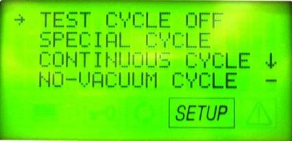
73 Your screen should look like this if you press the Plus/Up button 5 times. Press the Start/Stop button when your selected pause time is set. Start/Stop button Your screen should look like this. Press the Menu button 3 times. Menu button Your screen should look like this. Press the Start/Stop button. Start/Stop button Your screen should look like this. CC & SETUP on the display indicate you have selected continuous cycles. You can now select the cycle of your choice and it will run continuously until you run out of water. Note: If you wish to return the Bravo to its normal operating mode you will need to return to the Test Cycles screen and turn the Test Cycles OFF. 73
74 Bravo Maintenance Display Warning Messages The sterilizer periodically reminds the user about recommended routine maintenance operations that must be carried out in order to ensure the proper operation of the device. The reminder notices are displayed on the screen when a sterilization cycle is started. Warning Message Chamber Filter Cleaning Bacteriological Filter Replacement Door Gasket Replacement General Service Frequency Every 200 cycles Every 400 cycles Every 1000 cycles Every 3000 cycles The frequencies indicated have been calculated for standard use of the device, used correctly and positioned in a suitable environment. Should you notice a significant lose in performance, repeated occurrence of alarms or visible degradation of the parts subject to wear, it is advisable to carry out the maintenance operations earlier than the due dates programmed in the system. Bravo Maintenance Daily Weekly Monthly Annual or every 1000 cycles Every 3 Years or 3000 cycles Clean the door gasket and plate with a clean cotton cloth soaked in a weak solution of water and vinegar. Dry the surfaces and remove any residue before using the device. Clean external surfaces using a clean cotton cloth dampened with water and, if needed a neutral detergent. Clean the sterilization chamber and relative accessories. Disinfect external surfaces. Clean the internal distilled water tank. Safety valve maintenance. Clean (or replace) the drain filter. Replace the door gasket. Recommended complete maintenance of the sterilizer by an authorized dealer. 74


.")


75 Door Gasket Part # Clean the door gasket and front of chamber with a clean cotton cloth soaked in a weak solution of water and vinegar. Dry the surfaces and remove any residue before using the device. Install the new door gasket by pressing the gasket into its seat, first on top, then bottom, then both sides. Once seated on 4 sides, continue to press the remaining gasket completely into its seat. For the occasional disinfection of the external surfaces, you can use either denatured alcohol or detergents with a small percentage of sodium hypochlorite (or equivalent). Chamber Drain Filter Part # Cleaning & Replacing Unscrew the fitting from the lower front of the chamber. Remove the screen from the fitting. Note: Grab the screen on the solid end do not grab in the middle of the screen. You will damage the screen. Clean the inside of the screen. The screen may look clean on the outside but the inside will be dirty and clogged with debris. Gently insert clean screen into chamber fitting and screw fitting in finger tight. 75


76 Bacteriological Filter Part # To replace the bacteriological filter unscrew the filter counterclockwise and replace with new filter. Bacteriological Filter Cleaning the Internal Distilled Water Tank 1. Turn the main power switch OFF and unplug the unit. 2. If a Bravo Water Reservoir Drain Kit is installed on the Bravo insert the end of the tube into an empty container and remove the plug from the tube. Water Reservoir Drain Kit # S 3. If there is no internal drain tank tubing, go to the rear of the Bravo with an empty container and remove the plug to the Distilled Water Drain Port. Note: As soon as the plug is removed water will come out of the port. Distilled Water Drain Port 4. Wait until the internal tank is completely drained and reinstall the plug. 5. Prepare 1 gallon of distilled water mixed with 10% of pure alcohol and fill using the manual filling container. If you have a Bravo 2, remove the reservoir cap and pour the cleaning solution into the top of the Bravo. 6. Fill the internal tank completely with this solution and allow the solution to sit for 30 minutes. WARNING: DO NOT RUN ANY CYCLE DURING THIS PERIOD. 7. Now drain the internal tank and discard the solution. Close the drain port with a plug. 8. Fill the reservoir with distilled water and run one empty cycle of your choice. 76
77 Cleaning the internal tank Bravo 2 1. Arrange an empty container on the floor near the sterilizer and insert the free end of the tube. 2. Insert the other end of tube in the quick-coupling marked Service positioned on the front as shown in the figure below. 3. Allow the tank to empty completely, and then disconnect the tube. 4. Prepare 4 liters/1.06 US Gal of distilled water and 10 % of pure alcohol, such as isopropyl and then pour it into the distilled water tank following the procedure indicated in the chapter Loading Distilled Water until the maximum level has been reached. 5. Let the solution sit for 30 minutes. WARNING: DO NOT RUN ANY CYCLE DURING THIS PERIOD. 6. Repeat step 2 and completely empty the internal tank again (as in point 2). 7. Fill the reservoir with distilled water and run one empty cycle of your choice. 77


78 Bravo Distilled Water Reservoir Drain Kit Installation Instructions Part # S Turn the main power switch OFF and unplug the unit. Go to the rear of the Bravo with an empty container and remove the plug to the clean water drain port. Note: As soon as the plug is removed water will come out of the port. Distilled Water Drain Port Once the distilled water tank is drained install the elbow fitting into the distilled water drain port. 78


79 Connect the drain tubing to the elbow fitting using a tie wrap and install the plastic drain tube holder underneath the rear of the Bravo, below the elbow fitting. Feed the drain tubing through the holder. Mount the second drain tube holder underneath the front of the Bravo below the H2O drain sticker. Make sure the orange plug is installed into the end of the drain tubing. 79


80 Bravo Upgrade Kit Installation Instructions Kit Part # Bravo Door Motor Replacement Instructions Old Motor New Motor Remove covers Drain clean water & waste water reservoirs and turn Bravo on to its side or slide Bravo over the edge of a counter. Remove the plate on the bottom of the Bravo below the door motor. Door Motor cover plate Disconnect the white and black wires to the motor. This is a DC motor so the white wire must be connected to the terminal with the red dot. Insert a Phillips screwdriver with a shaft length of at least 5.5 inches through the opening where the cover plate was removed and remove 4 screws holding the motor assembly. Retain top coupling to reinstall with new motor. Screw Top Coupling Remove the old motor through the opening in the bottom of the Bravo and install the new motor and coupling retained when old motor was removed. Reconnect the white and black wires making sure the white wire is connected to the terminal with the red dot. When the Bravo is powered ON you will usually get a locking problem error code. Reset the new door motor using the following instructions. 80

81 Bravo Door Motor Reset for Gam PCB Remove the cover Remove the X21 jumper located above the battery X21 Jumper Push on the hidden key while turning the power switch ON The message Locking Device will be displayed on the LCD Release the hidden key and press the stop/start key to release the door locking mechanism Open the door and press the arrow up key to exit this condition and start the self test Switch off the Bravo at the end of the self test and reinstall jumper X21 Switch the Bravo ON and run a sterilization cycle Hidden Key Hidden Key Arrow Up Key Stop/Start Key Door Motor Reset for Troll PCB Push on the hidden key while turning the power switch ON The message Locking Device will be displayed on the LCD Release the hidden key and press the stop/start key to release the door locking mechanism Open the door and press the arrow up key to exit this condition and start the self test If the door overload function has been triggered, there is no more beeping sound when pressing the keypad remove the cover and reset the red button on the PCB. Red Button 81


 on the other side of the")

82 Bravo Power Switch Replacement Instructions Old Power Switch New Power Switch When replacing the power switch connect the wires from the fuse holders to the top terminals of the switch and connect the wires to the filter board to the bottom terminals of the switch. White or blue wires (neutral wires) should be on one side of the switch and black or brown wires (positive wires) on the other side of the switch. The wires can be brought through the mounting hole for the switch and connected to the switch. Then push the switch into the mounting hole and lock into place. 82


83 Bravo Fuse Holder Replacement New Fuse Holder Old Fuse Holder When replacing fuse holders connect white & blue wires to one fuse holder and black and brown wires to the other fuse holder. Bravo Rear Leg Replacement Old Leg New Leg Note: Requires 9/16 Allen Wrench 83


 the notch goes up. Notch The float switch wires connect to the top of the PCB on the left.")
84 Bravo Float Switch Replacement Instructions Old Float Switch (orange gasket) New Float Switch (black gasket) Remove cover Drain clean water & waste water reservoirs When replacing more than one float switch always complete installation of the first switch before removing the second switch so the wiring plugs do not get connected to the wrong terminals. The float switch for the waste water tank (part # ) will have a longer wire than the clean water reservoir float switches (part # ). When install the float switch always observe the direction of the notch on the rear of the switch. The waste water tank switch the notch goes down, the clean water reservoir lower switch (water level minimum) the notch goes down and the clean water reservoir upper switch (water level maximum) the notch goes up. Notch The float switch wires connect to the top of the PCB on the left. The waste water tank switch connects to terminal SS+, The clean water reservoir lower switch (minimum level) connects to terminal SC and the clean water reservoir upper switch (maximum level) connects to terminal SC+. SC+ SC- SS+ 84


85 Chamber Filter Fitting Replacement Old Chamber Filter Fitting New Chamber Filter Fitting Tubing Replacement Old Tubing New Tubing Replace tubing from water pump to steam generator and tubing from steam generator to chamber. 85
BRAVO AUTOCLAVES. Installation Notes. BRAVO 1 Quick Start Guide SD-402 Rev. 1.0 Copyright 2012 SciCan Ltd. All rights reserved
 BRAVO AUTOCLAVES Installation Notes BRAVO 1 Quick Start Guide SD-402 Rev. 1.0 Copyright 2012 SciCan Ltd. All rights reserved For questions, technical support, service and inquires, contact: Manufactured
Water Distiller Service Manual
 Water Distiller Service Manual Water Distiller Service Manual L70478WT 2008 Regal Ware, Inc. Table of Contents RECOMMENDED TOOLS... 2 GENERAL INSPECTION...3 BOILING CHAMBER TROUBLESHOOTING & REPAIRS Description...
TECHNICAL INFORMATION Touchtronic Clothes Dryers
 TECHNICAL INFORMATION Touchtronic Clothes Dryers Includes: T1302, T1303, T1322, T1329ci T1403 & T1405 2004 Miele This page intentionally left blank. Table of Contents GENERAL INFORMATION A. Warning and
Products documentation (REVISION DATE: 03/10/2011) OMFP6010 (60cm PIROLITIC OVEN)
 OMFP6010 (60cm PIROLITIC OVEN)") Products documentation (REVISION DATE: 03/10/2011) OMFP6010 (60cm PIROLITIC OVEN) Ovens Service Manual Models OMFP6010 CONTENTS This document has been published to be used for service only. The contents
Products documentation (REVISION DATE: 03/10/2011) OMFP6010 (60cm PIROLITIC OVEN) Ovens Service Manual Models OMFP6010 CONTENTS This document has been published to be used for service only. The contents
541D19 SERIES. Technical Manual. A Division of Aquion Partners L.P.
 541D19 SERIES Technical Manual A Division of Aquion Partners L.P. Table of Contents Introduction... Page 1 Technical Specifications... Page 2 Flow Diagrams... Page 3 Injector & Flow Control Selection Injector...
Full Size Canister Service Manual Riccar Models 1700 / 1800 Power Nozzles RPB-100 / RPB-220 / RPB-224 / RPB-250
 Full Size Canister Service Manual Riccar Models 1700 / 1800 Power Nozzles RPB-100 / RPB-220 / RPB-224 / RPB-250 Table of Contents I. General Full Size Canister Issues...2 A. Full Bag Indicator...2 1. General
Owner s Guide and Installation Manual
 Tribeca Owner s Guide and Installation Manual English Form# M6000-01 20120416 2012 Casablanca Fan Co. Welcome Your new Casablanca ceiling fan is an addition to your home or office that will provide comfort
Servicing manual. Wall-mounted condensing gas boiler 600 Series - 11S / 19S / 24S / 24C /2002 GB(EN) For trade use
 For trade use") GB122 7210 1300-12/2002 GB(EN) For trade use Servicing manual Wall-mounted condensing gas boiler 600 Series - 11S / 19S / 24S / 24C Please read thoroughly before attempting to diagnose fault List of contents
GB122 7210 1300-12/2002 GB(EN) For trade use Servicing manual Wall-mounted condensing gas boiler 600 Series - 11S / 19S / 24S / 24C Please read thoroughly before attempting to diagnose fault List of contents
Servicing manual. 600 Series - 11S / 19S / 24S / 24C. Wall-mounted condensing gas boiler. For trade use
 GB122 Servicing manual Wall-mounted condensing gas boiler 600 Series - 11S / 19S / 24S / 24C For trade use Please read thoroughly before attemting to diagnose fault 7217 4900 (03/2010) GB/IE List of contents
Model Series ELECTRIC WATER SYSTEM PUMP. PumpAgents.com - buy pumps and parts online. Model Series. Automatic Multi-Outlet FEATURES
 PumpAgents.com - Click here for Pricing/Ordering Model 36950-2 Series ELECTRIC WATER SYSTEM PUMP Automatic Multi-Outlet FEATURES Self-Priming Diaphragm Design Allows Dry Running Built-in Discharge Check
SuperKlean Washdown Products
 February 2012 DURAMIX 8000 INSTALLATION AND MAINTENANCE INSTRUCTIONS **DO NOT THROW AWAY AFTER INSTALLATION** **SAVE AND DISPLAY PROMINENTLY WHERE THIS EQUIPMENT IS USED** WARNING HIGH PRESSURE AND HOT
MEDICAL DEVICES SECTOR MANUAL FOR THE TECHNICIAN. Language: ENGLISH Cod: 9046 STEAM STERILIZER SERENA THE NEW GENERATION
 MEDICAL DEVICES SECTOR MANUAL FOR THE TECHNICIAN Language: ENGLISH Cod: 9046 STEAM STERILIZER SERENA THE NEW GENERATION Autoclave SERENA/Manual for technician/rev.01/23.05.12 Pagina 1 SUMMARY 1. ACCESS
Installation Instructions EFS Hand Washing Station
 Installation Instructions EFS Hand Washing Station Both water and soap are sequenced and dispensed from outlet. Override button allows for non potable, water-only dispensing. Lighted icons indicate the
MAINTENANCE MANUAL TAIYO SEIKI CO., LTD.
 MAINTENANCE MANUAL TAIYO SEIKI CO., LTD. Introduction This Maintenance Manual explains how to replace and adjust the major components of the Automatic Taping Machine when required in daily operation.
Geberit AquaClean 8000plus UP Service instructions
 Geberit AquaClean 8000plus UP Service instructions 01-2010 998.601.00.1 (00) Contents Contents ESD protection... 4 Service spare parts... 5 Fault clearance by fault pattern... 8 Fault clearance by error
The Danger signal indicates an immediately hazardous situation which, if not avoided, will result in death or serious injury.
 The Danger signal indicates an immediately hazardous situation which, if not avoided, will result in death or serious injury. The Warning signal alerts you to potential hazards or unsafe practices which,
TECH SHEET - DO NOT DISCARD PAGE
 TECH SHEET - DO NOT DISCARD PAGE 1 3. If this test mode has been entered successfully, all indicators on the console are illuminated for 5 seconds with 8:88 showing in the Estimated Time Remaining three-digit
WASHING MACHINE SERVICE MANUAL CAUTION READ THIS MANUAL CAREFULLY TO DIAGNOSE PROBLEMS CORRECTLY BEFORE SERVICING THE UNIT.
 WASHING MACHINE SERVICE MANUAL CAUTION READ THIS MANUAL CAREFULLY TO DIAGSE PROBLEMS CORRECTLY BEFORE SERVICING THE UNIT. MODEL : WM2240C* Jul. 2010 PRINTED IN KOREA P/No. : MFL30599179 CONTENTS 1.SPECIFICATIONS...
JOHN DEERE GATOR HPX/XUV 2 PASSENGER HEATER INSTALLATION INSTRUCTIONS (p/n: 9PH20S30)
") P. 1 of 12 JOHN DEERE GATOR HPX/XUV 2 PASSENGER HEATER INSTALLATION INSTRUCTIONS (p/n: 9PH20S30) Item: Qty: Description: 1 2 1 x 1 x 5/8 Tee Fitting 2 2 Plastic Snap-in Hose Grommet 3 4 1-1/2" Hose Clamps
P. 1 of 12 JOHN DEERE GATOR HPX/XUV 2 PASSENGER HEATER INSTALLATION INSTRUCTIONS (p/n: 9PH20S30) Item: Qty: Description: 1 2 1 x 1 x 5/8 Tee Fitting 2 2 Plastic Snap-in Hose Grommet 3 4 1-1/2" Hose Clamps
WASHING MACHINE READ THIS MANUAL CAREFULLY TO DIAGNOSE TROUBLE CORRECTLY BEFORE OFFERING SERVICE.
 website : http://www.lgeservice.com e-mail : http://lgeservice.com/techsup.html WASHING MACHINE SERVICE MANUAL CAUTION READ THIS MANUAL CAREFULLY TO DIAGSE TROUBLE CORRECTLY BEFORE OFFERING SERVICE. MODEL
1 ESMA, Inc. P. O. BOX 734 * SOUTH HOLLAND, IL * (800) * FAX (708)
 * FAX (708)") 1 2 Instructions for Ultrasonic Washer E789 (U.L. Approved) 1. INTRODUCTION The E789 Automatic Ultrasonic Washer automatically performs a cleaning cycle, the major steps of which are: Ultrasonic cleaning
1 2 Instructions for Ultrasonic Washer E789 (U.L. Approved) 1. INTRODUCTION The E789 Automatic Ultrasonic Washer automatically performs a cleaning cycle, the major steps of which are: Ultrasonic cleaning
FIREPLACE INSTALLATION
 CHECK GAS TYPE Use proper gas type for the fireplace unit you are installing. If you have conflicting gas types, do not install fireplace. See retailer where you purchased the fireplace for proper fireplace
MacDonald Steel Limited
 DELUXE FILLER / CROWNER MODEL - DFC4 1 REV 00 CAUTION / WARNING READ MANUAL BEFORE OPERATING MACHINE DO NOT EXCEED 50 PSI ON Co2 OR BEER LINES DO NOT EXCEED 100 F (35 C) ON Co2 OR BEER LINES DO NOT HOSE
Service Manual 26 Self Trimming Fireplace with 3 Stage Remote
 Service Manual 26 Self Trimming Fireplace with 3 Stage Remote Model Number: DF2690 MOD: 0 Dimplex North America Limited 1367 Industrial Road Cambridge ON Canada N1R 7G8 1-800-668-6663 www.dimplex.com REV
PARTS AND SERVICE MANUAL FOR THE 23 COMPACT FIREPLACE
 PARTS AND SERVICE MANUAL FOR THE 23 COMPACT FIREPLACE TABLE OF CONTENTS OPERATION PAGE 1 PARTS DRAWING PAGE 3 PARTS LIST PAGE 4 LIGHT BULB REPLACEMENT PAGE 5 HEATER ON/OFF SWITCH REPLACEMENT PAGE 6 THERMOSTAT
Operations Manual. Part Number: For Research Use Only
 Operations Manual Part Number: 470230-598 For Research Use Only Ph: 1-800-962-2660 - Web: www.wardsci.com Thank you for choosing our Bench top sterilizers. Prior to operating this instrument, please read
NOTICE . SAFE SERVICING PRACTICES. Electric Wall Oven with Electronic Oven Control
 SERVICE DATA SHEET 318047418 (0504) Rev. A Electric Wall Oven with Electronic Oven Control NOTICE This service data sheet is intended for use by persons having electrical and mechanical training and a
Service Manual 26 Self Trimming Export Fireplace with 3 Stage On/Off Remote
 Service Manual 26 Self Trimming Export Fireplace with 3 Stage On/Off Remote Model Numbers: DF2608-EU - MOD / to A DF2608-AU - MOD / Dimplex North America Limited 1367 Industrial Road Cambridge ON Canada
SERVICE MANUAL DISHWASHERS DIVA ACCESSIBILITY DISHWASHERS
 SERVICE MANUAL DISHWASHERS DIVA ELECTROLUX HOME PRODUCTS S.p.A. Publication no. Spares Operations Italy Corso Lino Zanussi,30 I - 33080 PORCIA /PN (ITALY) 599 38 70-09 Fax +39 0434 394096 EN DISHWASHERS
MODEL MC-UL592 MC-UL594 POWER SOURCE. 230V - 240V ~ 50 Hz MAX INPUT 1400 W 1500 W NOMINAL INPUT DIMENSIONS (W x L x H)
") Order Number: PMMA091040CE Vacuum Cleaner MC-UL592/MC-UL594 SPECIFICATION MODEL MC-UL592 MC-UL594 POWER SOURCE 230V - 240V ~ 50 Hz MAX INPUT 1400 W 1500 W NOMINAL INPUT DIMENSIONS (W x L x H) 1200-1300
Order Number: PMMA091040CE Vacuum Cleaner MC-UL592/MC-UL594 SPECIFICATION MODEL MC-UL592 MC-UL594 POWER SOURCE 230V - 240V ~ 50 Hz MAX INPUT 1400 W 1500 W NOMINAL INPUT DIMENSIONS (W x L x H) 1200-1300
L A signature series TA T N E RE O, A L L A T S IN
 signature series COMMERCIAL STEAM GENERATORS INSTALLATION, OPERATION AND MAINTENANCE MANUAL INSTALLATION MANUAL COMMERCIAL STEAM GENERATOR SIGNATURE SERIES (SS) INTRODUCTION Steam Sauna manufactures steam
Series 8920, 9200, 9300, 9400 Service Center Guide
 Series 8920, 9200, 9300, 9400 Service Center Guide 2005 BISSELL Homecare, Inc. Page 1 of 22 TABLE OF CONTENTS Product overview Page 3 Quick reference troubleshooting chart Page 4 UL recommended high voltage
APPENDIX 4. Thank you for choosing the Biomega BioClave steam sterilizer. HYDRAULIC DRAWING
 Thank you for choosing the Biomega BioClave steam sterilizer. Your steam sterilizer has been CE certified and designed with durability, reliability, and safety in mind. It is your responsibility to install
EN Instruction manual. gasprofi 1 SCS micro. The smallest laboratory gas burner with more safety. DIN 30665, part 1
 EN Instruction manual gasprofi 1 SCS micro The smallest laboratory gas burner with more safety DIN 30665, part 1 9a 9 7 3 2a 2 5 6 4 8 1 1 - Function knob 2, 2a - Dual knob: 2 - Gas adjustment 2a - Air
, '0''/).''$ /*'( 1'%* 00) ',))% *)) $ 3:36;$ !"## $%& '()*+,,,( '()*
.''$ /*'( 1'%* 00) ',))% *)) $ 3:36;$ !## $%& '()*+,,,( '()*") -'*.'/ 0,%,)$ *'/1', '0''/).''$23456533-7860/*'( -0''/).''10))'' $).''%0/*' 1'%* 00) ',))% *)) 0 ))))%))( 3 0''/).''0',''.$'.)%*., 0).''( 39523$ 3:36;$ 0/*'/'.''./ %.)'
-'*.'/ 0,%,)$ *'/1', '0''/).''$23456533-7860/*'( -0''/).''10))'' $).''%0/*' 1'%* 00) ',))% *)) 0 ))))%))( 3 0''/).''0',''.$'.)%*., 0).''( 39523$ 3:36;$ 0/*'/'.''./ %.)'
Dacor Technical Service
 Attention: This manual is just a section from the complete Wall Oven Service Manual. If you find that you require the complete service manual, which includes exploded views and parts, use and care information
Welcome! Today s topic: Small Home Repairs. November 14, 2015
 Welcome! Today s topic: Small Home Repairs November 14, 2015 Small Home Repairs Course Presented by Monique Johnson Environmental Green Solutions, LLC Objective Educate homeowners on basic technical skills
TECHNICAL INFORMATION T1500 Series Clothes Dryers
 TECHNICAL INFORMATION T1500 Series Clothes Dryers 2003 Miele - Table of Contents 1.0 CONSTRUCTION & DESIGN 1.1 Appliance Overview - Vented 1 1.2 Appliance Overview Condenser Models 2 1.3 Controls Overview
SERVICE MANUAL RIVA COMPACT M90E.24S M90E.28S M90E.32S Wall hung, fan flue, room sealed gas boiler
 Wall hung, fan flue, room sealed gas boiler SERVICE MNUL RIV COMPCT Models: G.C. ppl. No. M90E.24S 47--970--17 M90E.28S 47--970--18 M90E.32S 47--970--21 Leave this manual adjacent to the gas meter iasi
SERVICE MANUAL. Bradford White ElectriFLEX HD (Heavy Duty) Commercial Electric Water Heater CEHD SERIES Immersion Thermostat Models
 Commercial Electric Water Heater CEHD SERIES Immersion Thermostat Models") Bradford White ElectriFLEX HD (Heavy Duty) Commercial Electric Water Heater CEHD SERIES Immersion Thermostat Models SERVICE MANUAL Troubleshooting Guide and Instructions for Service (To be performed ONLY
Bradford White ElectriFLEX HD (Heavy Duty) Commercial Electric Water Heater CEHD SERIES Immersion Thermostat Models SERVICE MANUAL Troubleshooting Guide and Instructions for Service (To be performed ONLY
Service manual. Riva Plus HE. M296.28SR/C System boiler. Wall hung, fanflue, roomsealed, high efficiency gas boiler
 Wall hung, fanflue, roomsealed, high efficiency gas boiler Service manual Riva Plus HE Models G.C. ppl. No. M296.24SR/C 41-583-18 System boiler M296.28SR/C 41-583-19 System boiler Leave this manual adjacent
ZD-985 Desoldering Station
 ZD-985 Desoldering Station 2 Contents Contents... 3 Unpacking and Setting Up Your ZD-985 Desoldering Station... 4 Setting Up the Unit... 5 Auto Tip Saver Function... 8 Tips and Techniques... 8 Alloy Melt
Standard Downrod for ceilings 8-10 feet high. Longer Downrod for ceilings 10 feet or higher
 Table of Contents www.casablancafanco.com To register your fan, please visit: www.casablancafanco.com/register What to Expect with Your Installation Save your receipt for proof of purchase. Ceiling Bracket??
FLUSH WATER SAVER DUAL FLUSH KIT
 FLUSH CH ICE Version 12.26.08 FC002 WATER SAVER DUAL FLUSH KIT Dear Consumer; You have purchased a high quality water saver dual flush toilet valve kit. Every care has been taken during manufacturing to
Look for Service Centres, Point of Sale addresses and other information on: Version: Date: Mai 2011 Tools required:
 Description: C250 S/CS Electric Valve Part number: 23709 information on: www.thetford.eu Version: V2 Date: Mai 2011 Tools required: Remove Waste holding tank Remove bowl retainer bracket closest to the
VENT PCB DIAGNOSIS (ALL MODELS)
") Theory of Operation When keypad up/down button is pushed, contacts on the main PCB close between #12 and #13. Closing these contacts activates the triac for the sleeve motor which is connected to terminals
Theory of Operation When keypad up/down button is pushed, contacts on the main PCB close between #12 and #13. Closing these contacts activates the triac for the sleeve motor which is connected to terminals
Service Manual. Model Number VCX1525 VCX1525-WH. UL Part Number
 Service Manual Model Number VCX1525 VCX1525-WH UL Part Number 6904000100 IMPORTANT SAFETY INFORMATION: Always read this manual first before attempting to service this fireplace. For your safety, always
INSTALLATION & OPERATING INSTRUCTIONS
 INSTALLATION & OPERATING INSTRUCTIONS WARNING RISK OF ELECTRIC SHOCK. CONNECT ONLY TO A CIRCUIT PROTECTED BY A GROUND-FAULT CIRCUIT-INTERRUPTER. THE UNIT SHOULD BE INSTALLED BY A QUALIFIED SERVICE REPRESENTATIVE.
IMAGE V. Parts and Service Manual
 IMAGE 0V Section II Parts and Service Manual (88B) CLARKE TECHNOLOGY Image Operator's Manual Page AUTHORIZED PERSONNEL MAINTENANCE To Access Pump Motor. Remove brush housing from machine. See "Brush Motor
SERVICE MANUAL WASHING MACHINE MODEL : WD-10120FD WD-12120(5)FD WD-14120(5)FD FWD-12120(5)FD FWD-14120(5)FD CAUTION
FD WD-14120(5)FD FWD-12120(5)FD FWD-14120(5)FD CAUTION") website : http://www.lgeservice.com e-mail : http://lgeservice.com/techsup.html WASHING MACHINE SERVICE MANUAL CAUTION READ THIS MANUAL CAREFULLY TO DIAGSE TROUBLE CORRECTLY BEFORE OFFERING SERVICE. MODEL
website : http://www.lgeservice.com e-mail : http://lgeservice.com/techsup.html WASHING MACHINE SERVICE MANUAL CAUTION READ THIS MANUAL CAREFULLY TO DIAGSE TROUBLE CORRECTLY BEFORE OFFERING SERVICE. MODEL
Table of Contents 1. OVERVIEW SYSTEM LAYOUT SPECIFICATIONS FUNCTION... 11
 Table of Contents 1. OVERVIEW... 3 2. SYSTEM LAYOUT... 4 3. SPECIFICATIONS... 8 3.1 SYSTEM COMPONENTS...9 3.2 PLC INPUTS AND OUTPUTS...9 3.3 FUNCTION KEYS...10 3.4 DEFAULT SET POINTS AND TIMERS...10 4.
CEILING SPEAKER SYSTEM
 INSTRUCTION MANUAL CEILING SPEAKER SYSTEM F-2852C TABLE OF CONTENTS 1. SAFETY PRECAUTIONS... 2 2. GENERAL DESCRIPTION... 3 3. FEATURES... 3 4. NOMENCLATURE AND DIMENSIONS... 4 5. INSTALLATION... 5 7. REPAINTING
Models Series Series
 Models 31800-Series 31801-Series INDUSTRIAL DIAPHRAGM PUMPS 4 GPM/15 LPM FEATURES Self-Priming Easy Installation Can run dry without damage Low Amp Draw Flow to 4 GPM/15 LPM Compact Size Thermal Overload
ENGINEER S MANUAL No.01
 1-NEEDLE, UNISON FEED, LOCKSTITCH MACHINE (AUTOMATIC LUBRICATION) LU-1510 1-NEEDLE, UNISON FEED, LOCKSTITCH MACHINE WITH AUTOMATIC THREAD TRIMMER (AUTOMATIC LUBRICATION) LU-1510-7 1-NEEDLE, UNISON FEED,
Model 5060/5070. Letter Opener Revision 3 Brush Transport
 Model 5060/5070 Letter Opener Revision 3 Brush Transport ON/OFF, Reset Envelope Guide Ramp / Envelope Model 5060, 5070 Letter Opener Introduction Variable Speed Track Cover Counter (Optional) Deflector
Manual update 2016 MC37/MFC3600
 Manual update 2016 MC37/MFC3600 SETUP INSTRUCTIONS Evaporative cooling works on the principle of heat absorption by moisture evaporation. Simply put, heat is removed from the air as water evaporates. You
INSTALLATION. Glass Panel Doors (select models) CAUTION
 CAUTION") Location Do not install refrigerator near oven, radiator or other heat source. If not possible, shield refrigerator with cabinet material. Do not install where temperature falls below 55 F (13 C) or rises
Location Do not install refrigerator near oven, radiator or other heat source. If not possible, shield refrigerator with cabinet material. Do not install where temperature falls below 55 F (13 C) or rises
Summer Breeze Heater Service Manual
 Summer Breeze Heater Service Manual RSBH RSBH-SB RSBHP Revision: 1.0 Issued: 12-18-2012 Table of Contents I. Basic Assembly and Operation A. Safety Instructions... 2 B. Grounding Instructions... 3 C.
Models Series Series
 Models 3180-Series 3181-Series INDUSTRIAL DIAPHRAGM PUMPS Commercial Duty, 3 GPM/1 LPM FEATURES Sealless Easy Installation Run Dry Ability Flow to 3 GPM/1 LPM Self-Priming Low Amp Draw Thermal Overload
Heat Exchanger Block Replacement Instructions
 Series 1-4 Gas-fired water boiler Heat Exchanger Block Replacement Instructions Ultra-80 S1-4 Heat Exchanger Block Replacement Kit, Part No. 383-500-773 Ultra-105 S1-4 Heat Exchanger Block Replacement
Model UVGMD-AL MULTIVERSA CAN PACKAGING MACHINE Operators Manual
 Model UVGMD-AL MULTIVERSA CAN PACKAGING MACHINE Operators Manual MODEL UVGMD-AL INTRODUCTION Model UVGMD-AL offers your choice of atmospheric, vacuum only, vacuum then gas, or multiflush double seaming.
BF5000NT BF5000 EF2604 SF2603 DF2603
 PARTS & SERVICE MANUAL FOR THE 26 FIREPLACE MODEL NUMBER: BF5000NT BF5000 EF2604 SF2603 DF2603 7400520000R03 TABLE OF CONTENTS Table of Contents OPERATION... 2 EXPLODED DIAGRAM... 4 WIRING DIAGRAM... 5
Enteral Pump Instructions for Use To Assemble When the low
 Enteral Pump Instructions for Use Before initial use on battery power and after extended storage periods, the pump must be plugged into an AC power source for a minimum of 12 hours (pump may be operated
Explorer CleaningPartsDirect.com Carpet Extractor. Operator and Parts Manual. Home Find... Go To.. Model No.: Can.
 Explorer 1500 Carpet Extractor Model No.: 608808 609231 Can. Operator and Parts Manual CleaningPartsDirect.com 662-393-3045 NOBLES 12875 RANSOM STREET HOLLAND MI 49424 U.S.A. CUSTOMER SERVICE: 1-800-365-6625
INSTALLATION, OPERATION & MAINTENANCE MANUAL BERG TEMPERATURE CONTROL UNIT
 INSTALLATION, OPERATION & MAINTENANCE MANUAL BERG TEMPERATURE CONTROL UNIT TABLE OF CONTENTS Description Page # Introduction 3 Customer Support 3 Model Number Nomenclature 4 Control Panel 5 Display Panel
PUREPOWER SERIES CENTRAL VACUUM POWER UNITS PP500, PP600 & PP650
 USER GUIDE PUREPOWER SERIES CENTRAL VACUUM POWER UNITS PP500, PP600 & PP650 AB0039 FOR RESIDENTIAL USE ONLY!! MODELS SFDB-DQ, SFDB-DR AND SFDB-DS 30042509E IMPORTANT SAFETY INSTRUCTIONS SAVE THESE INSTRUCTIONS
A few simple steps to ensure perfect water, every time.
 A few simple steps to ensure perfect water, every time. Use and Care Guide MODELS: A9CTELECTRICSS A9ELECTRICBLK A9ELECTRICWHT Registration Please visit the website below to register your new water cooler
HydroCycle Vertical Aeroponic Systems
 HydroCycle Vertical Aeroponic Systems 2018 Growers Supply All Rights Reserved. Reproduction is prohibited without permission. *Actual system may differ from system shown. 113593 8' Vertical System (44
Manual for MC37/MFC3600
 Manual for MC37/MFC3600 SETUP INSTRUCTIONS Evaporative cooling works on the principle of heat absorption by moisture evaporation. Simply put, heat is removed from the air as water evaporates. You feel
TECHNICAL INFORMATION T 15xx Dryers
 TECHNICAL INFORMATION T 15xx Dryers 2010 Miele USA Table of Contents 1.0 2.0 3.0 T 15xx Dryers Construction and Design... 5 1.1 Appliance Overview Vented Models... 5 1.2 Appliance Overview Condenser Models...
P4200PM / P5000PM Remote Air Dryer User s Guide
 P4200PM / P5000PM Remote Air Dryer User s Guide 1. Welcome & Congratulations Congratulations on your purchase of a new PUREGAS P4200PM / P5000PM Air Dryer! We here at PUREGAS are very proud of our products
Part 3 Troubleshooting
 Part Troubleshooting What is in this part? This part contains the following chapters: Chapter See page Troubleshooting 2 Error Codes: Hydro-box 7 Error Codes: Outdoor Units Error Codes: System Malfunctions
Installation. Leveling
 Your refrigerator was packed carefully for shipment. Remove and discard shelf packaging and tape. Do not remove the serial plate. Location Do not install refrigerator near oven, radiator or other heat
FLAME115 INFRARED HEATER SERVICE MANUAL INDEX FIRE 115 WARNING
 FLAME115 INFRARED HEATER SERVICE MANUAL INDEX 1. CONTROLS AND COMPONENTS 2. FLAME CONTROL CYCLES 3. MAINTENANCE SCHEDULE 4. TROUBLESHOOTING GUIDE 5. REPAIR PROCEDURES 1. FAN MOTOR ASSEMBLY 2. FUEL FILTER
Get Cleaning... What s your Vax s model number? User Guide. Carpet Washer Vax Careline: AU: NZ:
 User Guide Vax Careline: AU: 1300 361 505 NZ: 0800 800 900 Carpet Washer Get Cleaning... What s your Vax s model number? W8 W8 W0 W0 W0 W W W W W What s your serial number? (Located on the base of the
Service Manual. Model Number: DWOP20R. UL Part Number
 Service Manual Model Number: DWOP20R UL Part Number 6909030100 IMPORTANT SAFETY INFORMATION: Always read this manual first before attempting to service this fireplace. For your safety, always comply with
OPERATING AND MAINTENANCE MANUAL
 Enter Serial No. here. In the event of an enquiry please quote this serial number. www.monoequip.com OPERATING AND MAINTENANCE MANUAL COMPACT SERIES 643 3 TRAY OVEN FILE 52 643 compact 3 TRAY RevA17 10-4-17
MODEL 4246 MIXER-GRINDER
 MODEL 4246 MIXER-GRINDER 4246S STANDARD (5 HP/1 HP) ML-134220 4246HD HEAVY DUTY (7.5 HP/1 HP) ML-134221 701 S. RIDGE AVENUE TROY, OHIO 45374-0001 937 332-3000 www.hobartcorp.com FORM 34850 (Dec. 2002)
Installing the Cisco ONS FAP-4 Fuse Alarm Panel
 Installing the Cisco ONS 15454-FAP-4 Fuse Alarm Panel Product Number: 15454-FAP-4= This document explains how to install, test, operate, and maintain the Cisco ONS 15454-FAP-4 fuse alarm panel. This document
Service manual. Type: TD25. Contents
 Service manual Type: TD25 Contents Introduction...3 Type overview...4 Programme...5 Indication of programme sequence...5 Options and settings...6 Variant settings...8 Test programme...9 Troubleshooting...11
FACSCalibur Startup Procedures
 FACSCalibur Startup Procedures Always turn on the FACSCalibur before turning on the computer when acquiring data. This enables the computer to recognize that the cytometer is connected. When analyzing
- website: Vax Ltd., Kingswood Road, Hampton Lovett, Droitwich, Worcestershire WR9 0QH, UK
 V-026PT User Guide.qxd 7/9/06 15:13 Page 12 EEC STATEMENT OF COMPLIANCE Manufacturer/EEC importer: Vax Limited, hereby on our own responsibility, declare that the product V-026PT is manufactured in compliance
Theory of Operation: M9/D & M11/D
 : M9/D & M11/D NOTE This document applies to the following models: M9/D (-020 thru -022) (-033 & -034) M11/D (-020 thru -022) (-033 & -034) Mode / System Page Power Up Mode... 2 Select Cycle Mode... 4
SERVICE MANUAL. Kleenmaid SMART oven OMFHS6010
 SERVICE MANUAL Kleenmaid SMART oven OMFHS6010 2 Contents 1. Product identification 4 2. DEMO mode (showroom operation) 5 3. Child Lock 6 4. Automatic power cut-off 7 5. Error Codes 8 6. Door assembly 9
ACME DIAGNOSTICS STANDARD OPERATING PROCEDURE
 ACME DIAGNOSTICS STANDARD OPERATING PROCEDURE Procedure Number: II.01.200a Effective Date: 09/14/99 Review and Update: 09/2003 TITLE: ADVIA 120 ROUTINE MAINTENANCE PURPOSE AND PRINCIPLE: The ADVIA 120
HydroCycle Vertical Aeroponic Systems
 HydroCycle Vertical Aeroponic Systems 2018 Growers Supply All Rights Reserved. Reproduction is prohibited without permission. 113700 4' Vertical System (24 Grow Sites) Revision date: 01.10.18 1 Important
Nexus FS Filtration Installation Guide. September 19, 2011
 Nexus FS Filtration Installation Guide September 19, 2011 DSW-Filtration Install Guide:05201011:rev-12122011 Technical Specifications Dimensions: Height: 43.5 Width: 11.65 Depth: 15 Weight: 34.39 LBS Electrical
Installation & Operating Guide
 5-036 HOT WATER TANK Installation & Operating Guide Read all instructions thoroughly. Keep this guide for future reference. Proof of purchase is required for Warranty. Staple receipt or proof of purchase
SERVICE MANUAL WASHING MACHINE MODEL: WM3431H*/WM3434H* WD-14312RD/WD-14316RD CAUTION
 Website: http://www.lgeservice.com [For U.S.A] www.lg.ca [For CANADA] E-mail: http://www.lgeservice.com/techsup.html WASHING MACHINE SERVICE MANUAL! CAUTION READ THIS MANUAL CAREFULLY TO DIAGSE PROBLEMS
SE300 Build Guide. SeeMeCNC Guides. SE300 Build Guide. Written By: SeeMeCNC seemecnc.dozuki.com/ Page 1 of 16
 SeeMeCNC Guides SE300 Build Guide Written By: SeeMeCNC 2018 seemecnc.dozuki.com/ Page 1 of 16 Step 1 SE300 Hot End Assembly This guide will show you how to assemble the SE300 hot end and effector platform.
Manual for MC91 SETUP INSTRUCTIONS
 Manual for MC91 SETUP INSTRUCTIONS Evaporative cooling works on the principle of heat absorption by moisture evaporation. Simply put, heat is removed from the air as water evaporates. You feel this principle
5800 Refrigerator Compressor Capacitor/Relay Kit
 5800 Refrigerator Compressor Capacitor/Relay Kit Instruction Sheet 60-4702-009 Revision B, January 25, 2016 Overview The refrigerator compressor relay and capacitor are components of the Teldyne Isco 4700
1998 DISHWASHERS Servicing and Troubleshooting
 CONSUMER SERVICES TECHNICAL EDUCATION GROUP PRESENTS KD-10 1998 DISHWASHERS Servicing and Troubleshooting MODELS DU800DWG DU801DWG DU805DWG DU810DWG DP840DWG DU840DWG DU850DWG DU890DWG DU910PFG DP920PFG
Service Manual for X9.5 and Older Models
 Service Manual for X9.5 and Older Models I. Common Issues... 2 A. Direct Air Motor... 2 A.1. Direct Air Motor will not run.... 2 A.2. Direct Air Motor is making a squealing sound.... 2 B. Full Bag Indicator
UF424 and UN324. Technical Service
 UF424 and UN324 Technical Service Technical Service 1-800-533-6006 Check out the new mobile ready website www.scotsman-ice.com/service Technical Service Virtual Business Card What you will learn Introduction
WASHING MACHINE READ THIS MANUAL CAREFULLY TO DIAGNOSE TROUBLE CORRECTLY BEFORE OFFERING SERVICE.
 website : http://www.lgeservice.com e-mail : http://lgeservice.com/techsup.html WASHING MACHINE SERVICE MANUAL CAUTION READ THIS MANUAL CAREFULLY TO DIAGSE TROUBLE CORRECTLY BEFORE OFFERING SERVICE. MODEL
INSTANT HOT WATER DISPENSER
 INSTANT HOT WATER DISPENSER Tank Installation Materials required (not provided) 2 mounting bracket screws (and 2 plastic anchors if attaching to drywall) Shut-Off valve and T fitting Components When you
Suits all KPF849 models
 Kambrook - Australia Ground Floor, Suite 2, 170-180 Bourke Rd Alexandria NSW 2015, Australia Locked Bag 2000 Botany NSW 1455 Customer Service Line 1300 139 798 Customer Service Fax 1800 621 337 www.kambrook.com.au
CBT LW MAINTENANCE GUIDE
 CBT LW MAINTENANCE GUIDE PICTOGRAMS Each Signifier displayed here is specific to this User Manual. Menu Previous Advance Note Tip Example Powder Feeder Mixing Bowl Weigh Scale CBP Tanks Control Panel PSD
Pet. Easy Guide. VAX Ltd., Kingswood Road, Hampton Lovett, Droitwich, Worcestershire, WR9 OQH, UK - website:
 V-027P Rapide Pet User Guide 10/7/07 10:05 Page 14 EEC STATEMENT OF COMPLIANCE Manufacturer/EEC importer: VAX Limited, hereby on our own responsibility declare that the products V-027/V-027PT/V-027P/CCW-701