SUPER JACK/ BIG JACK OWNER S MANUAL. Model No. s BJ90 - SJ125. Assembly Installation Operation Repair Parts SUPER JACK SJ125 BIG JACK BJ90
|
|
|
- MargaretMargaret Morris
- 6 years ago
- Views:
Transcription


1 SUPER JACK SJ125 OWNER S MANUAL Assembly Installation Operation Repair Parts Model No. s BJ90 - SJ125 CAUTION: Read Rules And Instructions Carefully For Safe Operation IMPORTANT: Installation must be made in accordance with state and local ordinances which may differ from this installation manual. BIG JACK BJ90 SUPER JACK/ BIG JACK Wood BURNING furnaces For your safety: Do not store or use gasoline or other flammable vapors and liquids in the vicinity of this or any other appliance. TESTED BY WARNOCK HERSEY INTERNATIONAL TO U/L 391 STANDARDS Alpha American Co., 10 Industrial Blvd., Palisade, MN
2 2
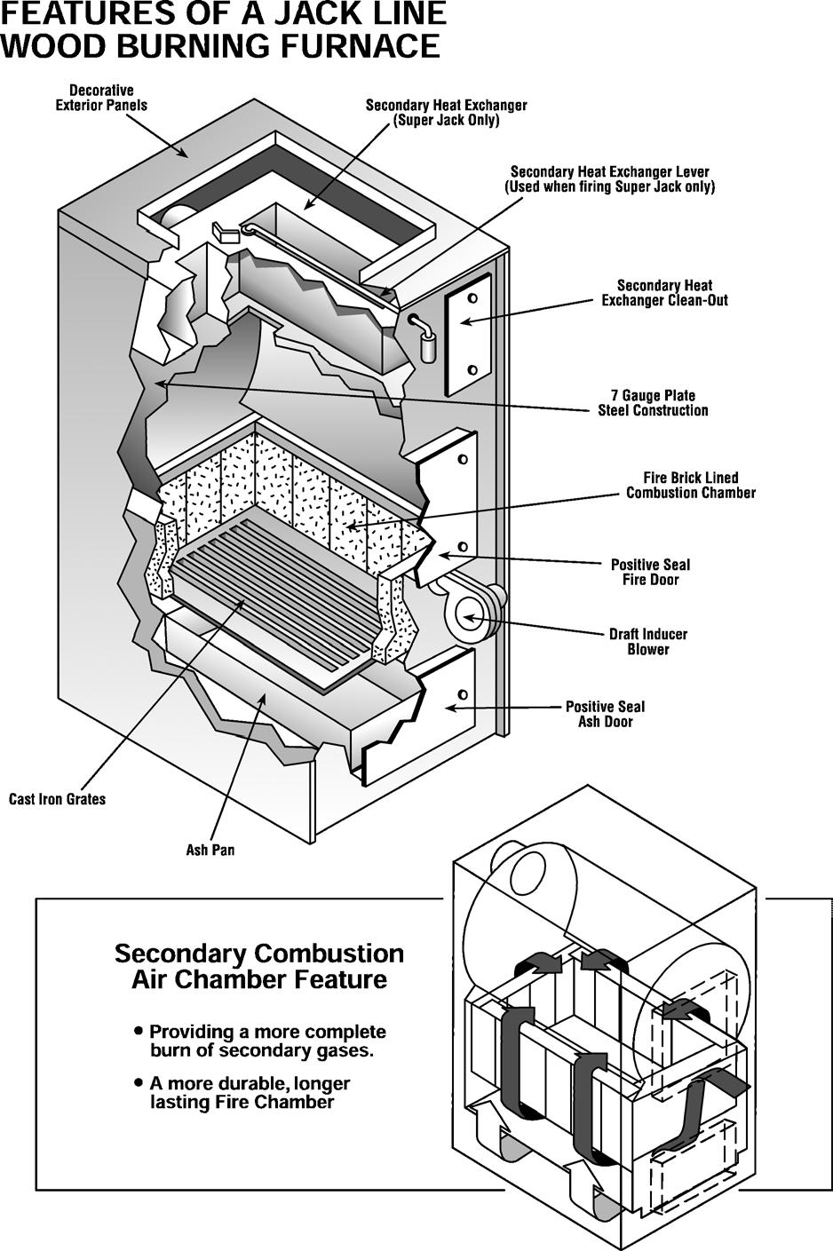
3 TABLE OF CONTENTS INTRODUCTION Furnace Specifications... 3 Features... 4 Dangers - Caution - Fire Hazards Typical Installation... 7 Unpacking & Inspection... 8 Rules for Safe Installation and Operation... 8 Locating the Furnace... 8 INSTALLATION Furnace Casing... 9 Combustion Blower... 8 Installing the Fan and Limit Control... 8 Electrical Wiring... 4 Wiring the Furnace (Diagram) Mounting Thermostat... 9 Connecting Smoke Pipe and Barometric Damper Control Clearances to Combustibles Ductwork Connection... 9 Proper Chimneys... 9 Draft Regulator Location Draft Regulator Installation Combustion Air Causes of Faulty Draft OPERATION Wood Firing the Unit MAINTENANCE Cleaning the Chimney, Smoke Pipe and Heat Exchanger.. 15 In Case of Chimney Fire Service Hints Parts Breakdown
4
5 DAnger risk of fire or explosion Do not burn garbage, gasoline, drain oil, kerosene, thinners, etc. WARNING Risk of fire - Firing door and ash door must be tightly closed during operation. - Do not operate with flue draft exceeding.03 W.C. - Do not store flammable materials within marked installation clearances. - Frequently inspect and clean heat exchanger, smoke pipe, and chimney of soot and/or creosote. - Do not connect this unit to a chimney flue serving another appliance. CAution Black surfaces are hot Keep children away. Do not touch. 5
6 DANGERS - CAUTION - FIRE HAZARDS (Burn wood logs or coal only) This furnace must be installed according to the manufacturers instructions, NFPA and local codes. Ducts and plenums shall be constructed entirely of sheet metal. Do not use flammable liquids to start a fire. Do not attempt to light a wood fire when gas or oil vapors are present. Do not install on a burnable floor. In the event of an electrical power failure, be sure ash door and fire door remain closed. Turn thermostat down to shut off combustion fan. Do not install a power humidifier on warm air plenum. Store all ashes in a metal container with a tight fitting lid. Allow ashes to cool before disposing of them. Be sure there is a sufficient supply of outside combustion air to the area where the furnace is located. Keep smoke pipe connection as short as possible with a minimum of 12-inch rise from the furnace to the chimney opening. Smoke pipe should be 24 gauge galvanized steel or heavier. This furnace has hot surfaces. Keep children away. Before servicing, allow furnace to cool. Shut off electricity. Familiarize yourself with this wood-burning furnace before leaving it unattended. Follow a regular service and maintenance schedule of furnace and chimney. IN THE EVENT OF A CHIMNEY FIRE, CALL FIRE DEPARTMENT, AND THEN BE SURE ALL FURNACE DOORS ARE CLOSED TIGHTLY. Important: Make these adjustments when installing.
7
8 INTRODUCTION This manual provides installation, operation, maintenance instructions and parts ordering information for the Big Jack Model BJ90 and the Super Jack Model SJ125 wood burning furnaces. IMPORTANT Please read all instructions carefully before attempting installation of this unit. Installation should only be done by a qualified installer. UNPACKING AND INSPECTION Inspect the furnace for visible damage. The furnace is shipped in one carton. Inside the wood loading door is another carton. It contains a gasket, conduit clip, wiring harness, fan and limit control, transformer-relay, combustion blower and barometric draft control. A circulating blower, if ordered, is shipped in a separate carton. RULES FOR SAFE INSTALLATION AND OPERATION 1. Read these rules and the instructions carefully. Failure to follow these rules and instructions could cause a malfunction of the furnace. This could result in death, serious bodily injury and/or property damage. 2. Check your local codes. The installation must comply with them. 3. Use only the type of fuel approved for this furnace. Over-firing will result in failure of heat exchanger and cause dangerous operation. 4. You must have a sufficient supply of combustion air to the area in which the furnace is located. (page 12) 5. Factory Built Chimneys: Connect this furnace to a chimney that complies with NFPA Factory built chimneys for use with wood-burning appliances shall comply with the HT requirements of UL 103 or CAN/ULC-S629-M87. This means you must install what is referred to as type HT all fuel chimney. Masonry Chimneys: Connect this furnace to a chimney that complies with NFPA A field constructed chimney of solid masonry units, bricks, stones, listed masonry chimney units, or reinforced Portland cement concrete that is lined with suitable chimney flue liners and built in accordance with the provisions of Chapter 4 of this standard. 6. Follow a regular service and maintenance schedule for efficient and safe operation. 7. Before servicing, allow furnace to cool. Always shut off electricity and fuel to furnace when working on it. This will prevent electrical shocks or burns. LOCATING THE FURNACE Locate the furnace as close to the chimney or flue as possible and near the center of the heat distribution system or next to primary furnace if used. Locate furnace where there is sufficient air supply for ventilation and proper combustion to comply with the minimum clearances required for fire protection and accessibility. See page 7 for typical installations. See also Combustion Air. (page 12) NOTE It is recommended that a 2", noncombustible raised pad be used for the furnace. This will prevent moisture from getting under the furnace and causing corrosion. PLACEMENT AND MINIMUM CLEARANCES For installation of our Jack Line furnace, the National Fire Protection Association (NFPA) Standard 90B specifies the minimum standard clearances to combustible surfaces as summarized below. CLEARANCE CHART Above Top of Plenum 18 From the Front 48 From Sides and Back 18 From Flue Pipe 18 From Existing Furnace 6 From Horizontal Warm Air Duct: Within 3 ft. of Plenum 18 Within 3 to 6 ft. Plenum 6 Beyond 6 ft. of Plenum 1 All heat runs 1 PARTS ASSEMBLY 1. Install the combustion blower & gasket to the provided opening just below the wood-loading door on the front of the furnace. 2. Attach the 4x4 junction box with the transformer/relay to the mount provided at the top right hand side of the front of the furnace. 3. Insert the fan-limit control into the sheet metal plenum approximately 6 inches above the furnace. 4. Wire according to the enclosed wiring instructions & local codes. (See page 13)
9 FURNACE CASING 1. The furnace is shipped unassembled in a carton attached to the furnace. 2. Insert the left and right side panels into the slots at the base of the furnace. 3. Place top panel over the front edge of the furnace and then into the side panels. MOUNTING THERMOSTAT & SUB-BASE Thermostat must be mounted on an interiior, centrally located wall away from direct sunlight and drafts and approximately 5 feet above the floor. REDUCED CLEARANCES Up to 50% less clearance between combustible walls and chimney connector to furnace and ducts is allowed if insulated according to NFPA Standard 90B or your local building code. This copyrighted book is available from the National Fire Protection Association Inc. 1 Batterymarch Park, Quincy, MA Phone orders: Their internet address is PROPER CHIMNEYS The National Fire Protection Association (NFPA) requires that all factory built chimneys be Listed and installed in accordance with conditions of the Listing in the manufacturers instructions. NFPA also requires that your chimney extend at least three (3) feet above the highest point when it passes through the roof and at least two (2) feet higher than any portion of the building within ten (10) feet of the chimney. Factory built chimneys must be what NFPA refers to NFPA as Type HT. HT is an abbreviation meaning High Temperature. Masonry Chimneys as referred to in NFPA , a field constructed chimney of solid masonry units, bricks, stones, listed masonry chimney units, or reinforced concrete that is lined with suitable chimney flue liners and built with the provisions of Chapter 4 of this standard. It is a mistake to assume that sheet metal, masonry, or asbestos-like board placed directly against a wall protects it. Materials installed in this manner give very little protection. These materials are good conductors, so they will be almost as hot on their backside as well as on their exposed side. Therefore, the combustible wall behind it is still a fire hazard. CAUTION Do not use any smoke pipes less than 24 gauge between furnace and chimney. CONNECTING SMOKE PIPE Set the smoke pipe end of the furnace as close to the chimney as possible. For every foot of lateral pipe, the rise of the smoke pipe toward the chimney must be at least one inch. Do not exceed 10 feet in length. A cleanout tee should be installed for removal of soot and fly ash. Do not install the smoke pipe longer than necessary to reach the chimney for purposes of trapping heat. The smoke outlet temperature is designed so that the heat emitted is needed to carry the by-products of combustion out through the chimney. The smoke pipe must not pass through any combustible material. The smoke pipe entrance into a masonry chimney should be at least 2 feet above the cleanout. The smoke pipe must not extend into the chimney beyond the inner face of the chimney liner. DO NOT CONNECT THIS FURNACE TO A CHIMNEY SERVING ANOTHER APPLIANCE WARNING Return air MUST NOT be drawn from inside the room where the furnace is located. WARNING Check your chimney. The chimney is a very important part of your heating system. It must be the right size, properly constructed and in good condition. No furnace can function properly with a bad chimney. The chimney must supply a draft of.03 Water Column. If possible, use a 15 foot or higher chimney. Add an additional foot to the chimney for each 1,000 feet of elevation above sea level. 9
10 INSTRUCTIONS FOR INSTALLING FIELD R-C BAROMETRIC DRAFT CONTROLS CHOOSING THE LOCATION Do not attach draft control to top or bottom of flue pipe, nor in a room separated from appliance. Best location is as close to appliances as possible. 10 VERTICAL FLUE: 1. Adjustment weight must be in RIGHT HAND SLOT (marked "V") in bracket on gate. 2. The arrow on flap at bottom of gate must line up with letter "V" on lower right part of gate. If it does not, remove flap, turn over and snap onto gate again. Flap can be removed by inserting small screwdriver at the back side of the gate between the gate and the flap, then pulling downward on flap. HORIZONTAL FLUE: 1. Adjustment weight must be in LEFT HAND SLOT (marked "H") in bracket on gate. 2. The arrow on flap at bottom of gate must line up with letter "H" on lower left part of gate. If it does not, remove flap, turn over and snap onto gate again. Bend outward the two ears at the front corners of collar and insert clamping screw. Bolt the remainder of the collar together. See Figure 2. Hold the collar against the flue in the EXACT position and mark the outline of the collar on the flue. Cut a hole in the flue about half an inch smaller than the marks. Then cut a series of short slits (about 3/8" or 1/2" deep) around the edges of the opening. After the collar is strapped on the flue the cut edges can be bent outward into the collar and thus make a better joint. WHEN FINISHED, THE OPENING INTO THE FLUE MUST BE EQUAL IN SIZE TO THE COLLAR OF THE DRAFT CONTROL. If flue pipe is made of material too heavy to bend out into the collar, the opening into the flue must be within 1/4" of the same diameter as the collar. INSTALLATION Strap the collar to the flue pipe and place the draft control into the collar, fastening it there by tightening the clamping screw in the collar. Use a spirit level to make sure that the control does not lean for - ward or backward but instead is plumb in both directions, regardless of whether the flue is horizontal, vertical or sloping. INITIAL SETTING OF BAROMETRIC CONTROL Set the control at a maximum of.03 or as low a draft as will give good combustion and meet the requirements for heat. Turn adjustment weight counter-clockwise to loosen, then slide in slot to proper position and tighten. Bracket is marked 2, 4, 6, and 8, which indicates draft settings of.02,.04, etc. (These are drafts in flue adjacent to control, not over-fire drafts.) A monometer must be used to accurately adjust flue draft.
11 FURNACE LOCATED IN CONFINED SPACE When the furnace is in a utility room, install two open grilles in a wall or door opening to the rest of the house. One grille will supply combustion air. Locate it near the floor. The other grille is for ventilation. Locate it close to the ceiling. Each grille must have a free area of not less than one square inch for each 1000 BTU/hr. of the total input rating of all the appliances in the confined space. (See Fig. 16) FOR EXAMPLE: Your furnace is rated at 150,000 BTU per hour. The water heater is rated 30,000 BTU per hour. The total is 180,000 BTU per hour. You need two grilles, each with 180 square inches of free opening. Metal grilles have about 60% free (open) area, so you need two metal grilles with 300 square inches each of louvered area. The height should be about half the width. FRESH AIR DUCT CAPACITIES Fresh air duct capacities for duct supplying fresh air. BTU Per Hour Input* 1/4 in. Mesh Wood Metal Screen Louvers Louvers Size BTU BTU BTU 3-1/4 x 12 in. 144,000 36, ,000 8 in. round 200,000 50, ,000 8 x 12 in. 382,000 96, ,000 8 x 16 in. 512, , ,000 * Based on opening covered by 1/4 inch mesh screen, wood or metal louvers. WARNING Enough air insures proper combustion and assures that no hazard will develop due to the lack of oxygen. WARNING Return air MUST NOT be drawn from inside the room where the furnace is located. NOTE If you have a fireplace, a kitchen fan, bath fan or water heater that vents to the outside, add enough duct size to your fresh air requirements to accommodate their air needs. 11
12 COMBUSTION AIR Make-up outside air to the furnace for proper fuel combustion must be provided by openings to the outside of the building. The openings of ducts supplying such make-up air shall have unobstructed areas not less than the area of the flue furnace pipe. NOTE Outside air is needed to replace the air used by the burner and wood combustion process. Outside air is also required to replace the air used for taking the by-products of combustion of the gas or oil burner and wood/coal smoke out the chimney. Outside air is also needed to replace any air expelled by kitchen or bathroom fans as well as water heater chimneys or fans. Failure to provide outside air to the area in which the furnace is located will result in a negative pressure or vacuum in the home. Smoke from the wood fire may not be drawn up the chimney, causing creosote buildup and sometimes causing smoke to enter the furnace room. WARNING You must provide for enough fresh air to assure proper combustion. The fire in the furnace uses oxygen and must have a continuous supply. The air in a house contains only enough oxygen to supply the furnace for a short time. Outside air must enter the house to replace that used by the burner. 12
13 13
14 OPERATION OF YOUR NEW JACK LINE WOOD BURNING FURNACE Check that your main blower and draft blower are in proper working order before lighting a fire. Turn thermostat upstairs to high temperature so draft blower turns on, then turn thermostat back to proper setting, turning draft blower off. Crumple a piece of paper, place inside, light paper, making sure you have a good draft (.03 water column). Now proceed with lighting a fire. 1. Open manual draft spinner 3-4 turns. 2. Make sure your smoke pipe damper is open. Place several pieces of crumpled paper in the center of your firebox. In a criss-cross pattern, place a couple handfuls of dry kindling wood 3/4 thickness, then several small dry pieces of firewood. Caution Never use chemicals or fluids such as gasoline, charcoal lighter fluid, drain oil or kerosene to light a fire in your Jack furnace. 3. Ignite the paper and close the door. Do not attempt to open door immediately after igniting the fire. There could be a flame flash out. 4. It will take a few minutes for the fire to establish itself. Once you have some good red hot burning embers, add larger pieces of wood. All chimneys and hook-ups act differently. After a while you will find out how your unit works best for you. 5. After a time you can adjust draft according to your needs. On air tight units, the burning time is controlled very much by the draft control on the furnace, contrary to the old type stove where the smoke pipe damper controlled the burning time. Your Jack Line furnace is capable of putting out many BTU s, so don t fully load your furnace or open all drafts fully until you have become familiar with the operation of the furnace. Keep in mind, a full load will not always give you the best results for your needs. NOTE With new steel, there is a small amount of oil or dirt on the metal you may smell an odor. This is normal during the first operation. Caution Use caution when opening loading door. Avoid opening loading door rapidly. This could cause flame to flash out door. This occurs when there is unburned fuel and a large amount of gases on top of the fire box. When the door is opened, oxygen is combined with the gases and ignites. helpful hints Set the draft to proper setting. The chimney, hook-ups, and kinds of wood will be a factor. Your Jack is capable of holding very large logs. DO NOT try to add a log that is larger than what you can easily place in the furnace. You will get best efficiency when you add only the amount of wood needed for a 4 to 6 hour burn. In the spring and in the fall when the weather is mild, burning large loads of wood for long periods may cause creosote. Stack temperature should be 300º for good burning. Again, depending on the weather, you may not need a full load of wood for a good overnight burn. You will get the best efficiency when you add only small amounts of wood. You can use wood of various shapes, diameters and lengths, but not to exceed your unit s specifications. Always try to place the logs so air has free flow between them, increasing combustion. ash removal When burning wood, every morning when there is just a bed of hot embers, run your poker over top of grates making sure grate slots are clear of burnt fuel. Once every week or two, depending on how much fuel you burn, ashes should be removed. Caution Never let ashes build up to grate level. This will reduce the life of your grate. To remove ashes, simply pull out your ash pan. But remember, the ash pan can get very hot. Dump ashes in a metal container with a lid that is placed on a non-combustible surface. Caution Never use anything but a metal container to put your ashes in. Every year fires are caused by emptying ashes into cardboard boxes or paper bags. 14
15 Maintenance 1. AT the start of the heating season... It is advisable to have your local furnace man inspect and service your furnace for the coming heating season. The furnace, smoke pipe and chimney should be cleaned and checked for repairs. 2. EMergency stops Shut off all electrical power at the main electric service entrance. 3. smoke pipe, heat exchanger and secondary heat exchanger Do not burn green or freshly felled wood. If you do, creosote and soot may build-up in the chimney, smoke pipe and secondary heat exchanger. This should be checked and cleaned several times each heating season. 4. Turn on regular (primary) furnace once every month to make sure it is functioning properly. Cleaning the chimney, smoke pipe and heat exchanger On a regular schedule, check for creosote and soot build-up in the chimney, smoke pipe and heat exchanger. They must be kept clean. Steel brushes are the safest for cleaning metal surfaces. Salt solutions and some chemicals may damage metal surfaces. When cleaning chimney, obtain a stiff steel brush with an extension handle and insert brush into chimney from the top. Continue brushing and sweeping downward until the full length of the chimney is cleaned. Open the clean-out door at the bottom of the chimney and sweep the debris into a plastic bag or container. When cleaning the smoke pipe or the heat exchanger, use a steel brush. IN CAse of chimney fire 1. Alert everyone in the house. 2. Call Fire Department immediately. 3. Shut any doors and air inlet dampers and draft control. This should take no longer than a few seconds. DO NOT use your furnace until a professional inspection has been made of your furnace, smoke pipe and chimney. 15
16 SERVICE HINTS Main blower vibrating when in use... POSSIBLE CAUSE Loose allen screw on squirrel cage Bad motor bearings Weight on squirrel cage wheel moved in shipment SOLUTION Tighten the allen screw, be sure squirrel cage did not move to one side or the other. Return blower for a replacement. Try to adjust it or return blower for replacement. Main blower or blowers continue to run... POSSIBLE CAUSE Fan limit control on unit is set too low Bad fan limit control Improper wiring SOLUTION Remove cover on fan limit control and set dials to the proper settings. Recommended temps: 160º on 130º off. NOTE: Never adjust fan limit by turning dial itself (picture of fan limit dials.) Check by turning one pointer down to where blower should turn off, if they don t, they need to be replaced. Go over wiring diagram again. Main blower or blowers won t turn on... POSSIBLE CAUSE Improper wiring Bad fan limit control SOLUTION Go over wiring diagram again. Replace fan limit control with a new one. Combustion blower staying on... POSSIBLE CAUSE Wall thermostat bad, check by turning temp. to 60º then check if draft blower is running Short in thermostat wire Home is not getting heat needed to satisfy wall thermostat Combustion blower not turning on... POSSIBLE CAUSE Switch on blower to the off position. Bad wall thermostat; check by turning it up to 80º and if the draft blower does not turn on, replace thermostat Limit control open SOLUTION Replace wall thermostat. Check all wiring again. Check on spec s chart to be sure your unit is large enough for your home. Be sure installation is proper, check with your local heating service provider. SOLUTION Replace thermostat. Check, then repair or replace. Smell an odor from the first fire in the home... POSSIBLE CAUSE New steel, small amounts of residue on steel SOLUTION This will disappear in a matter of hours. 16
17 Excessive creosote build-up. A small reminder, whatever kind of fuel you burn, there is some kind of residue build-up on the furnace and chimney. Same with wood no matter how good the conditions... POSSIBLE CAUSE The use of wet, frozen or unseasoned wood The use of soft wood, particularily those of high resin content such as plywood or blandex with glue Poor natural draft or an obstruction in the stove pipe or chimney flue Too long of burning times Inadequate amount of oxygen supplied to the combustion chamber Low fire or flue gas temperatures Uninsulated stove pipe or chimney flues, especially if construction is exterior to the house Air leaks in the stove pipe or chimney SOLUTION If you have to use wet wood, make loads smaller and burn them hotter. Avoid using if possible. Measure draft with gauge. Should be set at.03 water column. Smaller and hotter fires. Check page 12 of this manual for proper installation of outside combustion air to the furnace room. The air that goes out the chimney in the form of smoke must be replaced with fresh outside air. Smaller loads of wood and hotter fires. Stack temps should maintain minimum of 300º. Never use uninsulated pipes for chimneys. If installed on the outside of the house, INSULATE! Check chimney top to bottom. NOTE: Creosote is a tarry liquid or solid coming from distillation of wood during the combustion process. The heavier the build-ups, the greater chance of a chimney fire. NOTE: No matter how seasoned the wood, no matter how good the draft, you will always get a small amount of soot build-up. It should be cleaned out before the winter firing and during the mid-winter firing. Not getting heat in the home... POSSIBLE CAUSE Unit may be too small for your home; check specifications chart SOLUTION Replace with a larger unit. In colder weather your furnace will turn on once a day, one tank of fuel oil will last for a long time. Improper insulation in home, allowing heat to escape Improper hook up to furnace Fan limit control set too low Excessive amounts of smoke coming out of loading door when loading... POSSIBLE CAUSE Improper draft Chimney cap too close to top of chimney Too long of run of smoke pipe from Jack to chimney Negative pressure in home Reinsulate! Check installation drawings and/or consult your heating service provider. Check settings; refer to operation on proper settings and adjust accordingly. If needed to set higher, never exceed 180º on 150º off. SOLUTION Measure draft with gauge. Should be set at.03 Water Column. Relocate. CAUTION: Always open smoke pipe damper when loading. Relocate Jack closer to chimney. Install outside combustion air to furnace room. 17
18 FAULTY CHIMNEY AND/OR DRAFT PROBLEMS - CAUSES AND CURES A sound chimney system is imperative, especially when burning wood. Indoor chimneys, either masonry or type "HT" metal chimneys are best. Because warm air rises, a warm chimney allows the smoke and other by-products of combustion a natural exit up and out the chimney. Outdoor chimneys should be your last choice. Cold air naturally falls right down the cold chimney. Until the heat from the furnace warms the chimney, there is no natural draft to allow the smoke and by-products of combustion to rise naturally up the chimney. Outdoor class "A" triple wall is not acceptable because their thermo-siphon design will not allow the chimney to heat up, causing heavy creosote build-up and possible chimney fires. If you know your chimney is sound and you still have downdraft problems such as smoke or smell in the room in which the furnace is located, your chimney may not be operating properly. One or more of the following suggestions may be necessary. 1. Barometric draft control - This control must be set at.03. This is just a guide. It must be set with a draft gauge to prove that the chimney is drawing Combustion air - You must have outdoor combustion air introduced into the room where the furnace resides in the manner described on page 12. This method supplies air for combustion as well as replacing air that is drawn out by the chimney. Leaky doors and windows will not provide acceptable results. 3. Cold outdoor chimney - Sometimes in the spring or fall, or if you live in a mild climate, your heat demands are small and your chimney just does not heat up enough to induce a natural exit up draft, you may want to consider a power vent to force a draft up the chimney. A Model D-3 or AD-1 power venter is available from Tjurnland Manufacturing Co. in White Bear Lake, Minnesota or Model D1-2 is available from Field Controls Co., Kinston, North Carolina. 4. Chimney not tall enough - Your chimney must terminate at least 2 feet above the peak of the roof. Adding more chimney height sometimes cures the problem. (See Fig. 12, page 9) 5. Home located on side of hill - When the wind blows over a hill toward your home, the wind will fall. This could cause a down-draft into your chimney. Some common solutions to correct down-drafts are to add a chimney cap with a weather vane, add height to the chimney or add a power venter. 6. Tall trees near your home - If you have trees that are near to and higher than your home, a down-draft can occur when the wind blows. Correct the same way as if you live on the side of a hill or in a valley. 7. Chimney too large - Your chimney should not be more than 8 inches in diameter or the equivalent. If too large, the sides of the chimney may not heat up to create a natural draft. When this happens, the smoke and gases cool. They become heavy and other gases from the fire try to penetrate this heavy column of cool air. This results in back puffing, poor combustion or burning and may cause odors in your home. The solution is to improve your chimney or line it with 8-inch type 304 stainless steel flue liner. If your large chimney is outside masonry, insulate between the masonry and 8-inch flue pipe. top of CHIMNEy LoWER than SURRoUNdING objects REMEDY: ExtENd CHIMNEy ABoVE ALL objects WItHIN 30 feet CHIMNEy CAP PUSHEd over flue or flue obstructed By A VENtILAtoR REMEDY: REMoVE obstruction ACCUMULAtIoN of Soot or debris IN offset REMEDY: REMoVE AIR LEAKS through CRACKS IN flues ANd CHIMNEy disclosed By SMoKE test REMEDY: CLoSE LEAKS WItH CEMENt flue CAP RUSty ANd LEAKy REMEDY: CLoSE LEAKS ANotHER StoVE or HEAtER PIPE CoNNECtEd to SAME flue REMEDY: REMoVE & SEAL opening VENt PIPE PUSHEd INto flue REMEDY: MAKE ENd flush WItH INSIdE of flue LooSELy fitted VENt PIPE disclosed By SMoKE test REMEDY: CLoSE WItH CEMENt LooSELy fitted CLEANoUt door disclosed By SMoKE test REMEDY: CLoSE LEAKS WItH CEMENt opening BEtWEEN flues disclosed By SMoKE test REMEdy: CLoSE openings to MAKE A SMoKE test, USE A SPECIAL SMoKE BoMB ANd WItH top of CHIMNEy CLoSEd, LooK for LEAKS Trees Valley or Hill Wind Wind 18
19 19
20 20 BIG JACK BJ90 PARTS LIST
21 21
22 22 SUPER JACK SJ125 PARTS LIST
23
24 SUPER JACK/ BIG JACK Wood BURNING furnaces OWNER S MANUAL how to order repair parts When ordering repair parts, Always give the following information: Model No. s BJ90 - SJ125 Part Number Model Number Part description NAME OF ITEM CAUTION: Read Rules And Instructions Carefully For Safe Operation ALL PARTS MAY BE PURCHASED FROM ANY HEATING CONTRACTOR, OR direct FROM the FACTORY. IMPORTANT: Installation must be made in accordance with state and local ordinances which may differ from this installation manual. PHONE: FAX: info@yukon-eagle.com WEBSITE: Alpha American Co., 10 Industrial Blvd., Palisade, MN
Yukon klondike Eagle iv Wood/coal burning furnace
 YUKON EAGLE OWNER S MANUAL Assembly Installation Operation Repair Parts Model No. LW-000 Series CAUTION: Read Rules And Instructions Carefully For Safe Operation Yukon klondike Eagle iv Wood/coal burning
24 VAC SYSTEM CONTROL KIT
 24 VAC SYSTEM CONTROL KIT Model: CK-43 Tubing MG1 Barometric Draft Control The CK-43 is designed for use with the SWG Series Power Venter for controlling Natural Gas and L.P. Gas Draft Induced appliances.
INTRODUCTION TO HITZER STOVES INSTALLATION AND OPERATION
 INTRODUCTION TO HITZER STOVES INSTALLATION AND OPERATION Welcome to our proud team of HITZER heater owners. Your HITZER heater has the finest in Swiss craftsmanship and quality material to assure you that
CHIMNEY INSTALLATION. Technical Bulletin #1
 Technical Bulletin #1 CHIMNEY INSTALLATION A chimney performs two functions: it removes smoke and flue gases from the stove/furnace, and it provides draft for the fire. Draft is the term used to describe
Malm Fireplaces, Inc. 368 Yolanda Avenue, Santa Rosa, CA (707) Fax: (707)
 Fax: (707)") Malm Fireplaces, Inc. 368 Yolanda Avenue, Santa Rosa, CA 95404 (707) 523-7747 - Fax: (707) 571-8036 info@malmfireplaces.com Fire Drum 2 Tested to U/L Standards 1482 and 737 Assembly And Installation Instructions
Malm Fireplaces, Inc. 368 Yolanda Avenue, Santa Rosa, CA 95404 (707) 523-7747 - Fax: (707) 571-8036 info@malmfireplaces.com Fire Drum 2 Tested to U/L Standards 1482 and 737 Assembly And Installation Instructions
TABLE OF CONTENTS. Site preparation 2 Placement. 2 Chimney and stove pipe connections. 2
 TABLE OF CONTENTS SECTION TITLE PAGE 1. SITE PREPARATION AND INSTALLATION Site preparation 2 Placement. 2 Chimney and stove pipe connections. 2 Installation. 3 Water supply and return.. 3 Pressure/relief
Owner s Manual for. PennStoker
 Owner s Manual for PennStoker Table of Contents 1. Installation Placement ---------------------------------------------------------------------------------------- pg.3 Chimney Hook-up ---------------------------------------------------------------------------
SOLID FUEL WARM AIR FURNACE
 O H TBL AST MODEL 1303 Owners Manual SOLID FUEL WARM AIR ASSEMBLY INSTALLATION OPERATION REPAIR PARTS CAUTION READ ALL INSTRUCTIONS CAREFULLY BEFORE STARTING THE INSTALLATION OR OPERATING THE IMPROPER
HOMEOWNERS GUIDE FOR YOUR WOOD BURNING FIREPLACE
 P127003 01 P/N 127003-01 Rev. B 01/2016. HOMEOWNERS GUIDE FOR YOUR WOOD BURNING FIREPLACE Read this manual carefully before using your wood burning fireplace. Understand and observe all guidelines included
HOMEOWNERS GUIDE FOR YOUR WOOD BURNING FIREPLACE
 P127004 01 P/N 127004-01 Rev. B 01/2016. HOMEOWNERS GUIDE FOR YOUR WOOD BURNING FIREPLACE Read this manual carefully before using your wood burning fireplace. Understand and observe all guidelines included
Model 1200G. SOLID FUEL WARM AIR FURNACE Owners Manual
 O Model 1200G SOLID FUEL WARM AIR FURNACE Owners Manual H TBL AST *FOR PARALLEL INSTALLATION WITH AN EXISTING FORCED AIR, GAS OR OIL FIRED FURNACE (U.S. ONLY) *FOR INSTALLATION AS A CENTRAL FURNACE CAUTION:
OWNERS MANUAL MODEL DO110 & DO180 IS CERTIFIED TO: Unit Serial # Purchased From Company Address
 OWNERS MANUAL MODEL DO110 & DO180 IS CERTIFIED TO: UL 391 CAN/CSA B366.1 Unit Serial # Purchased From Company Address Name of Installer Installer Telephone # Date Installed IMPORTANT This manual must be
Shenandoah R65-E Wood & Coal Burning Heater Manual (EPA Exempt)
") Shenandoah R65-E Wood & Coal Burning Heater Manual (EPA Exempt) Installation & Operating Instructions Please read this entire manual before installation. Save these instructions. GENERAL INFORMATION Congratulations
Shenandoah R65-E Wood & Coal Burning Heater Manual (EPA Exempt) Installation & Operating Instructions Please read this entire manual before installation. Save these instructions. GENERAL INFORMATION Congratulations
24 VAC SYSTEM CONTROL KIT
 24 VAC SYSTEM CONTROL KIT Model: CK-91F and CK-91FG Designed for use with the SWG Series Power Venter for controlling Natural Gas or L.P. Gas draft induced appliances with a 24 VAC Gas Valve and a 30-millivolt
Shenandoah R65-E Coal Burning Heater Manual
 Shenandoah R65-E Coal Burning Heater Manual Installation & Operating Instructions Please read this entire manual before installation. Save these instructions. GENERAL INFORMATION Congratulations on your
OWNER'S MANUAL. Assembly Installation Operation Repair Parts Maintenance Tips
 OWNER'S MANUAL Assembly Installation Operation Repair Parts Maintenance Tips YUKON HUSKY/EAGLE I Model No. LWO-112 (Oil Fired) LWG-112 (Gas Fired) LWO-168 (Oil Fired) LWG-168 (Gas Fired) CAUTION: Read
Corn Flame Energy Corn Stove Model 3000
 Corn Flame Energy Corn Stove Model 3000 Installation and Operation Guide Read thoroughly before starting installation Save this manual for future reference SAFETY NOTICE If this stove is not properly installed,
MODEL CF CEILING SUPPORTED CHIMNEY
 Manufactured by Selkirk Canada Corp. - Hamilton, Ontario Installation Instructions for MODEL CF CEILING SUPPORTED CHIMNEY Round Top Storm Collar Flashing Attic Insulation Shield/Firestop Spacer Intermediate
NOT INSTALL THIS UNIT IN A MOBILE HOME.
 PIN-A-F -A-FIRE SPIN PIN ASSEMBLY AND INSTALLATION INSTRUCTIONS Listed by Warnock Hersey Tested to U/L Standard 737 & 1482 SAFETY NOTICE If this fireplace is not properly installed, a house fire may result.
Hitzer Energy Master II Stoker Furnace Model 710 Owner s Manual Installation and Operation
 Hitzer Energy Master II Stoker Furnace Model 710 Owner s Manual Installation and Operation Save this Manual Operating Instructions and Maintenance Enclosed. Thoroughly Read and Understand Instructions.
SOLID FUEL WARM AIR FURNACE
 O H TBL AST Models 1500 & 1537G OWNERS MANUAL SOLID FUEL WARM AIR *FOR PARALLEL INSTALLATION WITH EXISTING FORCED AIR-GAS OR OIL FIRED (U.S. ONLY) *FOR INSTALLATION AS A CENTRAL *THE 1500 & 1537G HOTBLAST
CHAPTER 8 CHIMNEYS AND VENTS
 CHAPTER 8 CHIMNEYS AND VENTS SECTION 801 GENERAL 801.1 Scope. This chapter shall govern the installation, maintenance, repair and approval of factory-built chimneys, chimney liners, vents and connectors.
qüé=`üáãåéó An effective chimney is an important part of any successful wood-burning system.
 8. qüé=`üáãåéó An effective chimney is an important part of any successful wood-burning system. How Chimneys Work An effective chimney is an important part of any successful wood-burning system. Many of
RSIF power venter USA CAN READ AND SAVE THESE INSTRUCTIONS! Installation and operation manual. Product information Chapters 1 + 2
 3002239 RSIF 2014-04-04 Installation and operation manual RSIF power venter READ AND SAVE THESE INSTRUCTIONS! Product information Chapters 1 + 2 Mechanical installation Chapter 3 Electrical installation
B.C.S. Shop Heaters 26, 30 & 36 (36 shown)
") BIOMASS COMBUSTION SYSTEMS, INC. 67 MILLBROOK ST., SUITE 502 WORCESTER, MA 01606 508-798-5970 - FAX 508-798-5971 B.C.S. Shop Heaters 26, 30 & 36 (36 shown) INSTALLATION MANUAL HAND FIRED SYSTEMS 8-09 Biomass
BIOMASS COMBUSTION SYSTEMS, INC. 67 MILLBROOK ST., SUITE 502 WORCESTER, MA 01606 508-798-5970 - FAX 508-798-5971 B.C.S. Shop Heaters 26, 30 & 36 (36 shown) INSTALLATION MANUAL HAND FIRED SYSTEMS 8-09 Biomass
CHAPTER 8 CHIMNEYS AND VENTS
 CHAPTER 8 CHIMNEYS AND VENTS SECTION 801 GENERAL 801.1 Scope. This chapter shall govern the installation, maintenance, repair and approval of factory-built chimneys, chimney liners, vents and connectors.
POWER VENTER SYSTEM. Model: PVO-300, PVO-600
 POWER VENTER SYSTEM Model: PVO-300, PVO-600 Included is one ETL and cetl listed Power Venter to be used primarily with a single 120VAC controlled oil fired furnace, boiler, or water heater. The PVO may
SIERRA RADIANT HEAT MAJESTIC OAK VENTED GAS LOG KIT INSTALLATION AND OPERATING INSTRUCTIONS
 SIERRA RADIANT HEAT MAJESTIC OAK VENTED GAS LOG KIT INSTALLATION AND OPERATING INSTRUCTIONS WARNING: If the information in this manual is not followed exactly, a fire or explosion may result causing property
SCOTTY WOOD FURNACE Model DB-102 OWNER S MANUAL IMPORTANT
 SCOTTY WOOD FURNACE Model DB-102 OWNER S MANUAL IMPORTANT READ OWNER S MANUAL THOROUGHLY BEFORE INSTALLING FURNACE OR LIGHTING FIRE. CONSULT LOCAL AUTHORITIES IF IN DOUBT ABOUT YOUR LOCAL FIRE SAFETY REGULATIONS.
POWER VENTER. Model: PVE Series
 POWER VENTER Model: PVE Series CONTENTS Typical Venting System Components... System Operation... Power Venter Sizing... Installation Safety Instructions... Installation of Power Venter... Connecting Power
VENTING CLEARANCES. BBT NORTH AMERICA Bosch Group. Bosch Water Heating 340 Mad River Park, Waitsfield, VT TWH-V-26 page 1 of 6 rev 01/06
 page 1 of 6 VENTING CLEARANCES The vents should not be obstructed and all joints properly fitted. Floors, ceilings and walls must be cut or framed to provide necessary clearance to vents. Metal strippings
RSIF Power Venter USA CAN. Product Information. ... Chapters Mechanical Installation. ... Chapter 3. Electrical Installation. ...
 Installation & Operating Manual RSIF Power Venter USA CAN Product Information... Chapters 1 + 2 Mechanical Installation... Chapter 3 Electrical Installation... Chapter 4 Start Up and Configuration... Chapter
SAFETY NOTICE FEATURES PREPARATIONS INSTALLATION OPERATION
 MODEL 21 CAST IRON INSERT/ TOWNSEND III NON-CATALYTIC/FREESTANDING ONLY/ROOM HEATER ALSO SUITABLE FOR MOBILE HOME INSTALLATION/ (MOBILE HOME INSTALLATION KIT AND INSTRUCTIONS MUST BE PURCHASED SEPARATE)
CHIMNEYS AND VENTS CHAPTER 8
 CHAPTER 8 CHIMNEYS AND VENTS SECTION 801 GENERAL 801.1 Scope. This chapter shall govern the installation, maintenance, repair and approval of factory-built chimneys, chimney liners, vents and connectors.
OIL FURNACE USER S INFORMATION MANUAL FOR THE OPERATION AND MAINTENANCE OF YOUR NEW OIL-FIRED FURNACE
 58CLA OIL FURNACE USER S INFORMATION MANUAL FOR THE OPERATION AND MAINTENANCE OF YOUR NEW OIL-FIRED FURNACE NOTE TO INSTALLER: THIS MANUAL MUST BE LEFT WITH THE EQUIPMENT USER. WELCOME TO A NEW GENERATION
OWNER S MANUAL. DS Greenhouse Blast GH450. Do Not Discard This Manual. High Efficiency Wood or Coal Green House Furnace. Model:
 DS Greenhouse Blast High Efficiency Wood or Coal Green House Furnace Do Not Discard This Manual Model: GH450 OWNER S MANUAL MADE IN USA By D.S. MACHINE SHOP Before you install or operate a DS Furnace,
PVE SERIES POWER VENTER SYSTEM MANUAL
 PVE SERIES POWER VENTER SYSTEM MANUAL Contents Page I. Typical Venting System Components 2 II. System Operation 3 III. Power Venter Sizing 3,4 IV. Installation Safety Instructions 5,6 V. Installation of
OWNERS MANUAL LIBERATOR ROCKET HEATER Model: RMH-1
 OWNERS MANUAL LIBERATOR ROCKET HEATER Model: RMH-1 SAVE THIS MANUAL FOR FUTURE REFERENCE LIBERATOR STOVE, LLC ST. LOUIS, MO. (314)-770-1043 Thank you for your purchase of the Liberator Rocket Heater. This
INSTRUCTION AND PARTS BOOK FOR MODELS 526, 2900, & 4000
 INSTRUCTION AND PARTS BOOK FOR MODELS 526, 2900, & 4000 Installation must be made in accordance with local and state codes which may differ from manual. Save these instructions. WOOD/COAL FURNACES Phone
Direct Vent System Required
 CB-200A Cottage Base Installation Instructions IMPORTANT: Read all instructions carefully before beginning the installation. This base must be installed by a qualified installing agency and in accordance
P.O. Box , Dallas, TX USER'S INFORMATION MANUAL Single-Stage Warm Air Gas Furnaces
 P.O. Box 799900, Dallas, TX 75379-9900 USER'S INFORMATION MANUAL Single-Stage Warm Air Gas Furnaces This is a safety alert symbol and should never be ignored. When you see this symbol on labels or in manuals,
HOMEOWNER'S GUIDE FOR YOUR CONTEMPO FIREPLACE TABLE OF CONTENTS
 10031 Southern SE Albuquerque NM 87123 505.291.0500 fax 505.291.9317 HOMEOWNER'S GUIDE FOR YOUR CONTEMPO FIREPLACE Before building your first fire, read this warranty and operation manual carefully. By
WARNING FIRE OR EXPLOSION HAZARD.
 2017 Lennox Industries Inc. Dallas, Texas, USA 506897-01 04/2017 Supersedes 10/2015 EL280DF SERIES GAS FURNACE Improper installation, adjustment, alteration, service or maintenance can cause property damage,
GAS FIRED BOILERS FOR FORCED HOT WATER VENTING ADDENDUM. ECR International Ltd. - Olsen Division P.O. Box 900 Wallaceburg, Ont.
 ODV-B GAS FIRED BOILERS FOR FORCED HOT WATER VENTING ADDENDUM ECR International Ltd. - Olsen Division P.O. Box 900 Wallaceburg, Ont. N8A5E5 TABLE OF CONTENTS HORIZONTAL PIPING... PAGES 1-10 WARNINGS...
2012 INTERNATIONAL FUEL GAS CODE VENTS
 2012 INTERNATIONAL FUEL GAS CODE SECTION 502 (IFGC) VENTS 502.1 General. All vents, except as provided in Section 503.7, shall be listed and labeled. Type B and BW vents shall be tested in accordance with
USER'S INFORMATION MANUAL
 USER'S INFORMATION MANUAL SERIES DV GAS FIRED HOT WATER HEATING BOILER WARNING: If the information in this manual is not followed exactly, a fire or explosion may result causing property damage, personal
USER S INFORMATION MANUAL
 USER S INFORMATION MANUAL UPFLOW & DOWNFLOW/HORIZONTAL CONDENSING GAS FURNACES SAFETY Recognize this symbol as an indication of Important Safety Information If not installed, operated and maintained in
Use, Care, and Installation Guide
 Use, Care, and Installation Guide Model PSU-E30AS XP022421(1) 182766 Safety Notice... 2-3 List of Materials... 4 D ucting Calculation Sheet... 5 Mounting Height & Clearance... 6 Ducting Options... 7 Hood
Installation Instructions Remote Blowers
 Installation Instructions Remote Blowers Models: REMP3, REMP16 Suitable for use in a household cooking area. Suitable for use with solid state controls. To complete this blower, a Dacor hood assembly or
104 MK II WOOD-BURNING STOVE
 104 MK II WOOD-BURNING STOVE SAFETY NOTICE PLEASE READ THIS ENTIRE MANUAL BEFORE YOU INSTALL AND USE YOUR NEW ROOM HEATER. FAILURE TO FOLLOW INSTRUCTIONS MAY RESULT IN PROPERTY DAMAGE, BODILY INJURY OR
NOTE TO INSTALLER: THIS MANUAL MUST BE LEFT WITH THE EQUIPMENT USER.
 c_::_':_-_:_ r'" _" "_1 WARNING: If the information in this manual is not followed exactly, a fire or explosion may Iresult causing property damage, personal injury or [loss of life. m m m Do not store
HOMEOWNERS GUIDE FOR YOUR WOOD BURNING FIREPLACE
 P127003 01 P/N 127003-01 Rev. C 02/2018 HOMEOWNERS GUIDE FOR YOUR WOOD BURNING FIREPLACE Read this manual carefully before using your wood burning fireplace. Understand and observe all guidelines included
Integrated Ventilation System
 Integrated Ventilation System For use with models: IVS1, IVSR1, IVS2, IVSR2 Installation Instructions Part No. 65278 Rev. K Table of Contents Important Safety Instructions... 1 Important Information About
SOLID FUEL WARM AIR FURNACE
 O H TBL AST Model 300/400 OWNERS MANUAL SOLID FUEL WARM AIR *FOR PARALLEL INSTALLATION WITH EXISTING FORCED AIR-GAS OR OIL FIRED (U.S. ONLY) *FOR INSTALLATION AS A CENTRAL *CERTIFIED UNDER ANSI/UL 39 &
Model 1537Q. SOLID FUEL WARM AIR FURNACE Owners Manual
 Model 1537Q SOLID FUEL WARM AIR Owners Manual TM *FOR PARALLEL INSTALLATION WITH AN EXISTING FORCED AIR, GAS OR OIL FIRED (U.S. ONLY) *FOR INSTALLATION AS A CENTRAL CAUTION: Read All Instructions Carefully
USER'S INFORMATION MANUAL
 USER'S INFORMATION MANUAL SERIES ODVB GAS FIRED HOT WATER HEATING BOILER WARNING: If the information in this manual is not followed exactly, a fire or explosion may result causing property damage, personal
RS Chimney Fan For Gas & Oil Applications. Installation & Operating Manual USA CAN
 Installation & Operating Manual 3000270 10.01 USA CAN RS Chimney Fan For Gas & Oil Applications 1200 Northmeadow Parkway, STE 180 Roswell, GA 30076 (770) 587-3238 (800) 255-2923 Fax (770) 587-4731 info@exhausto.com
USER S INFORMATION MANUAL
 USER S INFORMATION MANUAL UPFLOW, DOWNFLOW, UPFLOW/HORIZONTAL & HORIZONTAL ONLY INDUCED DRAFT GAS FURNACES Recognize this symbol as an indication of Important Safety Information If the information in this
INSTALLATION AND OPERATION MANUAL GAS SKILLETS MODELS: GTS-30 GTS-40
 INSTALLATION AND OPERATION MANUAL GAS SKILLETS MODELS: GTS-30 GTS-40 CROWN FOOD SERVICE EQUIPMENT LTD. 70 OAKDALE ROAD, DOWNSVIEW, (TORONTO), ONTARIO, CANADA, M3N 1V9 TELEPHONE: (416) 746-2358, FAX: (416)
SPECIFICATIONS PART NAME
 SPECIFICATIONS MODEL High HEAT RATING Low FUEL TANK CAPACITY BURNING TIME DIMENSIONS(W x D x H) WEIGHT VOLTAGE / FREQUENCY ELECTRICAL CONSUMPTION LC-S27 9,900 BTU / 2.9 kw 2,900 BTU / 0.8 kw 4.0 lit. 14.2~
USER S INFORMATION MANUAL
 USER S INFORMATION MANUAL UPFLOW/HORIZONTAL & DOWNFLOW TWO STAGE INDUCED DRAFT GAS FURNACES Recognize this symbol as an indication of Important Safety Information If the information in this manual is not
Installation Instructions
 Installation Instructions Models: ODGO324-MTCH, Grand Oak Match Light Gas Log Sets Installation and service of this appliance should be performed by qualified personnel. Hearth & Home Technologies suggests
MODELS LFP4218/LFP6018 TOP VENT GAS FIREPLACE
 MODELS LFP4218/LFP6018 TOP VENT GAS FIREPLACE PFS APPROVED FOR NATURAL GAS OR PROPANE GAS Z21.50-2014 If your plans do not allow for the venting system as outlined previously in the installing chimney/vent
INSTALLATION OPERATION AND SERVICE MANUAL
 INSTALLATION OPERATION AND SERVICE MANUAL THE OLD SALEM COLLECTION VENT FREE REGENCY COAL BASKET complies with ANSI Z21.11.2 THIS ONLINE MANUAL IS FOR PLANNING PUPOSES ONLY. CAREFULLY READ BEFORE PURCHASING.
Internet Version for Reference Only INDUCED DRAFT COMMERCIAL WATER HEATERS SUPPLEMENT INSTRUCTIONS TO PART #
 INDUCED DRAFT COMMERCIAL WATER HEATERS SUPPLEMENT INSTRUCTIONS TO PART #238-39387-00 THIS INSTRUCTION SUPPLEMENT IS ONLY INTENDED TO GIVE INSTALLATION INSTRUCTIONS AND INFORMATION RELATED TO THE INDUCED
24 VAC SYSTEM CONTROL KIT Model: CK-91F and CK-91FG
 24 VAC SYSTEM CONTROL KIT Model: CK-91F and CK-91FG Designed for use with the SWG Series Power Venter for controlling Natural Gas or L.P. Gas draft induced appliances with a 24 VAC Gas Valve and a 30-millivolt
SOLID FUEL WARM AIR FURNACE
 O H TBL AST Model 1300/1400 OWNERS MANUAL SOLID FUEL WARM AIR FURNACE *FOR PARALLEL INSTALLATION WITH EXISTING FORCED AIR-GAS OR OIL FIRED FURNACE (U.S. ONLY) *FOR INSTALLATION AS A CENTRAL FURNACE *CERTIFIED
ML180UH SERIES GAS FURNACE WARNING WARNING
 2017 Lennox Industries Inc. Dallas, Texas, USA 506525-01 04/2017 Supersedes 10/2015 ML180UH SERIES GAS FURNACE Improper installation, adjustment, alteration, service or maintenance can cause property damage,
WARNING FIRE OR EXPLOSION HAZARD.
 2017 Lennox Industries Inc. Dallas, Texas, USA 506698-01 04/2017 Supersedes 10/2015 SL280DFV SERIES GAS FURNACE Improper installation, adjustment, alteration, service or maintenance can cause property
Maintenance 50 Serie CAUTION. Before resetting your electronic card that displays an error code. OVERHEAT MESSAGE
 29-10-2013 CAUTION Before resetting your electronic card that displays an error code. OVERHEAT MESSAGE Service the stove COMPLETELY as described in this manual. Check the chimney pipe. BLOCKED FLUE MESSAGE
USER'S MANUAL PGE Single Package Rooftop
 USER'S MANUAL PGE Single Package Rooftop Gas Heating/Electric Cooling Units Sizes 036-150 3 to 12-1/2 Tons NOTE TO INSTALLER: This manual should be left with the equipment owner. WARNING: If the information
OIL-FIRED CENTRAL FURNACE
 OIL-FIRED CENTRAL FURNACE Installation, Operation, and Service Manual With Users Information Section Models: CSHB60-90XE CSHB60-90XP c WARNING: Do NOT store or use gasoline or other flammable vapors and
St. Croix Greenfield Installation Manual
 St. Croix Greenfield Installation Manual Table of Contents General Information... 1 Installation Check List... 2 Approved Installations... 3 Exhaust Venting... 4 Venting - Approved Materials... 4 Venting-Typical
EL195UHE SERIES GAS FURNACE WARNING WARNING
 2012 Lennox Industries Inc. Dallas, Texas, USA 506737-01 12/2012 Supersedes 06/2011 EL195UHE SERIES GAS FURNACE Improper installation, adjustment, alteration, service or maintenance can cause property
EL296UHV SERIES GAS FURNACE WARNING WARNING
 2011 Lennox Industries Inc. Dallas, Texas, USA 506769 01 08/2012 Supersedes 10/2011 EL296UHV SERIES GAS FURNACE Improper installation, adjustment, alteration, service or maintenance can cause property
G61MPV SERIES GAS FURNACE WARNING
 2003 Lennox Industries Inc. Dallas, Texas, USA 504,809M 03/2009 Supersedes 06/2003 G61MPV SERIES GAS FURNACE Litho U.S.A. FIRE OR EXPLOSION HAZARD. Failure to follow safety warnings exactly could result
Bosch 80% AFUE Gas Furnace BGS80 Model
 Bosch 80% AFUE Gas Furnace BGS80 Model 4-Way Multipoise Category I Fan-Assisted Furnace User's Information Manual 3124627 2 Bosch 80% AFUE Gas Furnace User's Information Manual Data subject to change 06.2018
READ AND SAVE THESE INSTRUCTIONS READ CAREFULLY BEFORE ATTEMPTING TO ASSEMBLE, INSTALL, OPERATE OR MAINTAIN THE PRODUCT DESCRIBED. PROTECT YOURSELF AN
 READ AND SAVE THESE INSTRUCTIONS READ CAREFULLY BEFORE ATTEMPTING TO ASSEMBLE, INSTALL, OPERATE OR MAINTAIN THE PRODUCT DESCRIBED. PROTECT YOURSELF AND OTHERS BY OBSERVING ALL SAFETY INFORMATION. FAILURE
Do not use this vent pipe or fittings for venting incinerators of any kind.
 ! CAUTION! Do not use this vent pipe or fittings for venting incinerators of any kind. C.S.A. Certified For Natural Gas Or Propane Tested For 100 LBS. ASME Working Pressure For correct installation of
Oil Furnace USER S INFORMATION MANUAL FOR THE OPERATION AND MAINTENANCE OF YOUR NEW OIL-FIRED FURNACE
 Oil Furnace USER S INFORMATION MANUAL FOR THE OPERATION AND MAINTENANCE OF YOUR NEW OIL-FIRED FURNACE MODEL PO8LAA LOW-BOY NOTE TO INSTALLER: THIS MANUAL MUST BE LEFT WITH THE EQUIPMENT USER. MODEL PO8UAA
DOMESTIC WATER HEATER OIL FIRED
 DOMESTIC WATER HEATER OIL FIRED Models : CMO32-II CMO32-II-R CMO50-II CMO32-II & CMO32-II-R INSTALLER / SERVICE TECHNICIAN: USE THE INFORMATION IN THIS MANUAL FOR THE INSTALLATION AND SERVICING OF THE
Technical Datasheet. FHG-S Models 28, and 45. Benefits at a Glance: State Route 22 Salem, NY 12865
 FHG-S Models 28, and 45 Technical Datasheet FrÖling FHG-S The FHG-S is a patented, wood-fired gasification boiler available in two sizes with outputs from 102,500-153,500 Btu/hr. Benefits at a Glance:
Fig. 1 - Unit PGD4, PGS4, WPG4
 OWNER S MANUAL 14 SEER Single -Package Air Conditioner and Gas Furnace System with R -410A Refrigerant Single Phase 2 to 5 Nominal Tons Three Phase 3 to 5 Nominal Tons PGD4andPGS4SeriesE,WPG4SeriesB Fig.
SAUNA HEATER INSTALLATION AND OPERATING MANUAL
 SAUNA HEATER INSTALLATION AND OPERATING MANUAL Type Stoveman 13 Models 13R; 13R-M; 13; 13-M; 13R-LS; 13R-M-LS; 13-M-LS; 13-LS Heating output in the sauna room 15.4 kw Sauna room cubage 6-13 m³ Fuel Wood
MANUAL WARNING FIRE OR EXPLOSION HAZARD. SL280UHNV SERIES WHAT TO DO IF YOU SMELL GAS:
 U S E R S I N F O R M AT I O N MANUAL 2017 Lennox Industries Inc. Dallas, Texas, USA SL280UHNV SERIES 507650-01 10/2017 Improper installation, adjustment, alteration, service or maintenance can cause property
EL195DFE SERIES GAS FURNACE WARNING
 2011 Lennox Industries Inc. Dallas, Texas, USA 506739 01 06/2011 EL195DFE SERIES GAS FURNACE Litho U.S.A. FIRE OR EXPLOSION HAZARD. Failure to follow safety warnings exactly could result in serious injury,
SYSTEM CONTROL KIT. Model: CK-62. Designed for use on SWG Series Power Vent Hoods for controlling oil fired heating appliances with 120 VAC controls.
 SYSTEM CONTROL KIT Model: CK-62 Designed for use on SWG Series Power Vent Hoods for controlling oil fired heating appliances with 120 VAC controls. ITEMS INCLUDED IN KIT: 1) Junction box with mounted pressure
UNVENTED (VENT-FREE) GAS LOG HEATER
 GAS LOG HEATER") LO UNVENTED (VENT-FREE) GAS LOG HEATER TM OWNER S OPERATION AND INSTALLATION MANUAL ("A" Models) 18", 24", and 30" Remote-Ready ( C Models) 18", 24", and 30" Variable Manually-Controlled PILOT OFF HI (
LO UNVENTED (VENT-FREE) GAS LOG HEATER TM OWNER S OPERATION AND INSTALLATION MANUAL ("A" Models) 18", 24", and 30" Remote-Ready ( C Models) 18", 24", and 30" Variable Manually-Controlled PILOT OFF HI (
User s Information Manual
 48AJ,AK,AW,AY020-060 Single-Package Rooftop Gas Heating Units with COMFORTLINK Controls and Scroll Compressors User s Information Manual NOTE TO INSTALLER This manual should be left with the equipment
DR-180 Through the Wall Exhaust Fan PRODUCT MANUAL & INSTALLATION GUIDE
 DR-180 Through the Exhaust Fan PRODUCT MANUAL & INSTALLATION GUIDE READ AND SAVE THESE INSTRUCTIONS READ CAREFULLY BEFORE ATTEMPTING TO ASSEMBLE, INSTALL, OPERATE OR MAINTAIN THE PRODUCT DESCRIBED. PROTECT
Technical Datasheet. Solo Innova Models 30 and 50. Benefits at a Glance: Solo Innova
 Solo Innova Models 30 and 50 Technical Datasheet Solo Innova Solo Innova is a patented, wood-fired gasification boiler available in two sizes with outputs from 102,500 to 170,700 Btu/hr. Benefits at a
Dovre 700CBW Cast Iron Wood Stove INSTALLATION INSTRUCTIONS 700G/1095
 Dovre 700CBW Cast Iron Wood Stove INSTALLATION INSTRUCTIONS 700G/1095 Before commencing with the installation it is important that these instructions are read and fully understood. The DOVRE 700CBW is
INDUCED DRAFT HIGHBOY AND COUNTERFLOW/HORIZONTAL GAS FURNACE
 INDUCED DRAFT HIGHBOY AND COUNTERFLOW/HORIZONTAL GAS FURNACE USERS INFORMATION MANUAL MODELS FOR USE WITH NATURAL GAS MHA-50N, MHA-75N, MHA-100N, MHA-125N, MDA-50N, MDA-75N, MDA-100N, MDA-125N FOR USE
Packaged Gas/Electric Units. Owner s Guide to Operating and Maintaining Your Gas/Electric Unit
 Packaged Gas/Electric Units Owner s Guide to Operating and Maintaining Your Gas/Electric Unit ELECTRICAL SHOCK HAZARD. FIRE OR EXPLOSION HAZARD Disconnect power at fuse box or service panel before performing
Chimney Fire Prevention
 Chimney Fire Prevention Ways to Avoid Chimney Fires Use seasoned wood Build smaller, hotter fires that burn more completely and produce less smoke Never burn cardboard boxes, wrapping paper, trash, rubber,
SERVICE AND INSTALLATION MANUAL MODELS HDO(H) OIL FOR YOUR SAFETY
 OIL FOR YOUR SAFETY") Bousquet Technologies Inc. 2121, Nobel, Ste Julie, Quebec, Canada, J3E1Z9 SERVICE AND INSTALLATION MANUAL MODELS HDO(H) OIL Oil-Fired air heater for industrial and commercial use. FOR YOUR SAFETY Do not
Bousquet Technologies Inc. 2121, Nobel, Ste Julie, Quebec, Canada, J3E1Z9 SERVICE AND INSTALLATION MANUAL MODELS HDO(H) OIL Oil-Fired air heater for industrial and commercial use. FOR YOUR SAFETY Do not
A-250, A-350, & A-450 Warm Air Furnace
 A-250, A-350, & A-450 Warm Air Furnace Operating instructions and maintenance enclosed Thoroughly read and understand instructions Always leave this manual with stove owner Follow the instructions within
IMPORTANT INSTRUCTIONS - OPERATING MANUAL
 IMPORTANT INSTRUCTIONS - OPERATING MANUAL Models: AK80LSL, AK100LSL Exhaust Fan READ AND SAVE THESE INSTRUCTIONS READ CAREFULLY BEFORE ATTEMPTING TO ASSEMBLE, INSTALL, OPERATE OR MAINTAIN THE PRODUCT DESCRIBED.
INSTALLATION INSTRUCTIONS
 INSTALLATION INSTRUCTIONS FACTORY BUILT CHIMNEY CONNECTOR A MAJOR CAUSE OF CHIMNEY CONNECTOR RELATED FIRES IS FAILURE TO MAINTAIN REQUIRED CLEARANCES (AIR SPACES) TO COMBUSTIBLE MATERIALS. IT IS OF THE
ROYAL ENGLISH OAK AND WINCHESTER OAK UNVENTED (VENT-FREE) GAS LOG HEATER
 GAS LOG HEATER") TM ROYAL ENGLISH OAK AND WINCHESTER OAK UNVENTED (VENT-FREE) GAS LOG HEATER OWNER S OPERATION AND MANUAL 18" and 24" Variable Manually- Controlled Models CGS2718P, CGS2718N CGS3124P, CGS3124N CLD3018PA,
TM ROYAL ENGLISH OAK AND WINCHESTER OAK UNVENTED (VENT-FREE) GAS LOG HEATER OWNER S OPERATION AND MANUAL 18" and 24" Variable Manually- Controlled Models CGS2718P, CGS2718N CGS3124P, CGS3124N CLD3018PA,