Sky Air. Product catalogue 2017 for professionals. Get ahead of the competition R-32 IS AN INDUSTRY REVOLUTION. BE PART OF IT.
|
|
|
- Hilary Holland
- 6 years ago
- Views:
Transcription

1 Sky Air Product catalogue 2017 for professionals R-32 IS AN INDUSTRY REVOLUTION. BE PART OF IT. Get ahead of the competition
2 i2
3 i3


4 The future is in your hands Define the future of A/C Introducing the new Sky Air A-series with ultra-efficient Bluevolution R32 technology, available in three models: the world-class Alpha, Advance and Active. The new Sky Air A-series delivers future-proofed, best-in-class climate control for your business and customers. Design flexibility. More compact. Quieter. With an extended operating range in all climate conditions. Help is at hand. Quicker and easier installation and usability, even for replacement systems. Daikin at the heart of the system. Reduced running costs and drastically lowered environmental impact. All thanks to Daikin s tried, tested and trusted technology. Geared for comfort. Advanced remote control possibilities, geared to your customers individual needs. Get ahead of the competition. Talk to Daikin about Sky Air today. 2
5 Sky Air Intro Table of contents Discover the Sky Air A-series 4 7 reasons why Sky Air is unique in the market 6 A solution for every application 12 Indoor units 15 Outdoor units 89 Biddle air curtains 110 Ventilation 113 Control Systems 127 Options & accessories 155 Tools and platforms 163 Technical Drawings 171 3

6 Discover Sky Air A-series on page 92 4

7 Get ahead of the competition Sky Air Intro Europe s first light commercial system using R-32 refrigerant R-32 Global Warming Potential (GWP) is 68% lower than the industry standard R-410A Highest efficiency (SEER up to 8.02) in the market Does not require yearly refrigerant containment checks, which reduces maintenance costs 16% less refrigerant charge App Control Control your device at anytime from anywhere Intuitive Via smartphone, tablet or cloud Lighter and more compact units for easy installation. Unique single fan range up to 14 kw 3-row heat exchanger Unique 3-row heat exchanger to allow compact casing up to 14 kw Redesigned pivoting front plate for easy access to vital system components New 7-segment display to do outdoor unit settings and view operating conditions 5

8 ARGUE CARDS Sky Air, the solution for the light commercial sector. 7 reasons why Sky Air is unique in the market 1 NEW Full Sky Air R-32 range delivering future-proofed, best-in-class climate control More details on page 92 System Type Model Product name PG kw 9.5 kw 12.1 kw 13.4 kw RZAG-MV Industry leading technology for commercial applications --Dedicated solution for infrastructure cooling --Variable Refrigerant Temperature --Maximum piping length up to 85m --Replacement technology --Extended operation range down to -20 C in both heating and cooling --Pair, twin, triple and double twin application RZAG-MY1 102 RZASG-MV1 103 Air cooled Heat pump --Technology and comfort combined for commercial applications --Very compact and easy to install outdoor units --Maximum piping length up to 50m --Replacement technology --Operation range down to -15 C both cooling and in heating --Pair, twin, triple and double twin application RZASG-MY1 103 AZAS-MV Ideal solution for busy environments and small shops --Very compact and easy to install outdoor units --Maximum piping length up to 30m --Replacement technology --Easy-to-mount outdoor units: roof, terrace or wall --Exclusively offered for pair applications AZAS-MY1 104 Full indoor line up available for R-32 and R-410A (over 45 different models) 6
9 2 NEW High energy efficiency Top seasonal efficiency SEER up to 8.02 and A++ label in cooling and heating Variable Refrigerant Temperature that automatically adapts the refrigerant temperature to the load Round flow and concealed ceiling units with auto cleaning filter Sky Air Intro 3 Best comfort NEW 4 NEW 5 NEW NEW 6 7 Variable Refrigerant Temperature preventing cold draughts Low sound indoor and outdoor units Presence and floor sensors direct the air flow away from persons, while ensuring an even temperature distribution Operation down to -20 C in heating and cooling operation Fresh air intake integrated in indoor unit Top reliability For infrastructure cooling unique boosted capacity indoor unit systems duty rotation control Refrigerant cooled PCB New refrigerant passes keeping heat exchanger and drain holes completely open at all times Most extensive testing before new units leave the factory Widest support network and after sales service All spare parts available in Europe Market leading controls Remote connectivity Intuitive app control Daikin Cloud Service offering online control, energy monitoring and comparison of multiple sites User-friendly wired remote controller with premium design BRC1H51 Intuitive touch button control 3 color versions Advanced settings can be easily done via your smartphone Dedicated control solutions for retail applications for infrastructure cooling Superior aesthetics Fully flat cassette design unit that integrates fully flat into the ceiling Auto cleaning units ensure dirt-free ceilings with high efficiency filters for regular and dust prone areas Unique installation benefits presence sensor floor sensor bottom plate refrigerant pass Tablet BRC1H51W NEW 4-way blow ceiling suspended cassette (FUA) for rooms without false ceiling. Plug & play Daikin air handling unit with ERQ condensing units Total solution for cooling, heating, air curtains and ventilation Dedicated assymetric combinations for infrastructure cooling Reliably replace Daikin and non-daikin systems without the need for pipe cleaning thanks to the new hepta filtration Use up to 4 indoor units linked to one outdoor unit for long or irregularly shaped rooms 7

10 Always in control, no matter where you are Online Controller Simple control from your smartphone Control your device at anytime from anywhere For single shop control 3rd party products and services integration via IFTTT More details on page 130 All unified indoor units connectable Connectable units overview: Ceiling mounted FCAHG-G FCAG-A FFA-A Concealed ceiling FDXM-F3 FBA-A FDA-A ADEQ-C Wall mounted FAA-A Ceiling suspended FHA-A FUA-A Floor standing FVA-A FNA-A If this, then that IFTTT is a solution that connects compatible 3rd party products and services (smart meters, lights, thermostats,...), so they work best for you. BRP069A81 Intelligent Tablet Controller From one to sites Tablet DCC601A51 User-friendly touch screen to centrally control your A/C and alarms Connects to the Daikin Cloud Service Built for multi-site control and monitoring Installers and technical managers can see alarms so they can provide remote assistance DAIKIN CLOUD SERVICE LOCAL CONTROL More details on page 140 Customer Installer/ technical manager 8

11 Unique auto cleaning technology Sky Air Intro Reduce running costs Automatic filter cleaning ensures high efficiencies and low maintenance costs because the filter is always clean Gradual loss of efficiency due to dirty filter Efficiency profile change for duct indoor unit during operation 100% 0% start 6 months 12 months Up to 20% Energy is saved thanks to automatic filter cleaning Minimal time required for filter cleaning The dust box can be emptied with a vacuum cleaner for fast and easy cleaning No more dirty ceilings Unique technology Unique and innovative filter technology inspired by the Daikin auto cleaning cassette Improved indoor air quality Optimum airflow eliminates draft and insulates sound How does it work? 1 Scheduled automatic filter cleaning 2 Dust collects in a dust box that s integrated into the unit 3 The dust can easily be removed with a vacuum cleaner airflow direction UNIQUE PATENDED SOLUTION Concealed ceiling units Ideal for hotels and residential applications Cleaning team /owner can clean the filter More details on page 34 Combination table Round flow cassette Ideal for retail Staff/owner can clean the filter No need to use a ladder to reach the unit More details on page 22 Split / Sky Air VRV FDXM-F3 FXDQ-A BAE20A62 BAE20A82 BAE20A102 Sky Air VRV FCAG-A FCAHG-G FXFQ-A BYCQ140DG9 BYCQ140DGF9 (fine mesh) 9

12 Multi zoning kit for concealed ceiling units The multi-zoning system is a room-by-room controller. It is fitted with motorised dampers, which immediately adapt using Daikin ducted solutions. This system supports control of up to 8 zones via a centralised thermostat located in the main room and individual thermostats for each of the zones. Benefits Increased comfort Increases comfort levels by allowing more individual zone control --Up to 8 individual zones can be served thanks to separate modulating dampers --Individual thermostat for room-by-room or zone-by-zone control Easy to install Automatic air flow adjustment according to the demand Easy to install, integrates with the Daikin indoor units and system controls Time saving as plenum comes fully pre-assembled with dampers, and control boards Reduces the amount of refrigerant required in the installation Plug and play plenum Concealed ceiling unit How does it work? 20 C Individual zone thermostats Blueface - Airzone Main Thermostat Color graphic interface for controlling zones Wired communication 21 C Airzone Zone Thermostat Graphic interface with low-energy e-ink screen for controlling zones Radio communication 19 C Zoning box: fully pre-assembled plenum with dampers Airzone Zone Thermostat Thermostat with buttons for controlling the temperature Radio communication Motorized dampers Electronic control panel AZCE6BLUEFACECB AZCE6THINKRB AZCE6LITERB Compatibility 10 Number of motorised dampers Standard Ceiling Void Compact Ceiling Void Reference Dimensions H x L x D (mm) FDXM-F3 FBA-A ADEQ-C FXDQ-A3 FXSQ-A AZEZ6DAIST07XS2 930 x 300 x 454 AZEZ6DAIST07S2 AZEZ6DAIST07XS3 930 x 300 x 454 AZEZ6DAIST07S3 AZEZ6DAIST07S4 930 x 300 x 454 AZEZ6DAIST07M4 1,140 x 300 x 454 AZEZ6DAIST07M5 1,425 x 300 x 454 AZEZ6DAIST07L5 AZEZ6DAIST07M6 1,638 x 300 x 454 AZEZ6DAIST07L6 AZEZ6DAIST07L7 1,425 x 515 x 454 AZEZ6DAIST07XL7 AZEZ6DAIST07L8 1,425 x 515 x 454 AZEZ6DAIST07XL8 2 AZEZ6DAISL01S2 720 x 210 x AZEZ6DAISL01S3 720 x 210 x AZEZ6DAISL01M4 930 x 210 x AZEZ6DAISL01L5 1,140 x 210 x 444


13 Sky Air Intro Infrastructure cooling Infrastructure cooling For rooms and enclosures that require round-the-clock cooling Where continuous uptime is the absolute requirement for server data protection Reliable Efficient Flexible Between 20-40% sensible capacity increase Guaranteed system operation: Oversized indoor units boost cooling capacity and prevent freeze-ups on the indoor side Wide operating range envelope: operation range in cooling down to -20 C and up to +52 C Optimum return on investment: Lowers running costs by using highly efficient direct expansion cooling systems Lower running costs compared to other DX systems and water based chillers. Minimises environmental impact with A++ energy labels Reduces mechanical cooling and energy consumption with the free cooling option for single phase systems Scalable in capacity Improved infrastructure control and management Lower physical footprint since no floor space is occupied Wide range of indoor units to suit application preferences (ceiling suspended cassettes, wall mounted indoors, concealed ceiling ducted type indoors) Duty rotation application example SYSTEM 1 FBA140 IN OPERATION SYSTEM 2 FBA140 STANDBY SYSTEM 1 FBA140 STANDBY SYSTEM 2 FBA140 IN OPERATION BRC1H51 or BRC1E53* Standard includes duty rotation functionality RZAG100 RZAG100 BRC1H51W 11


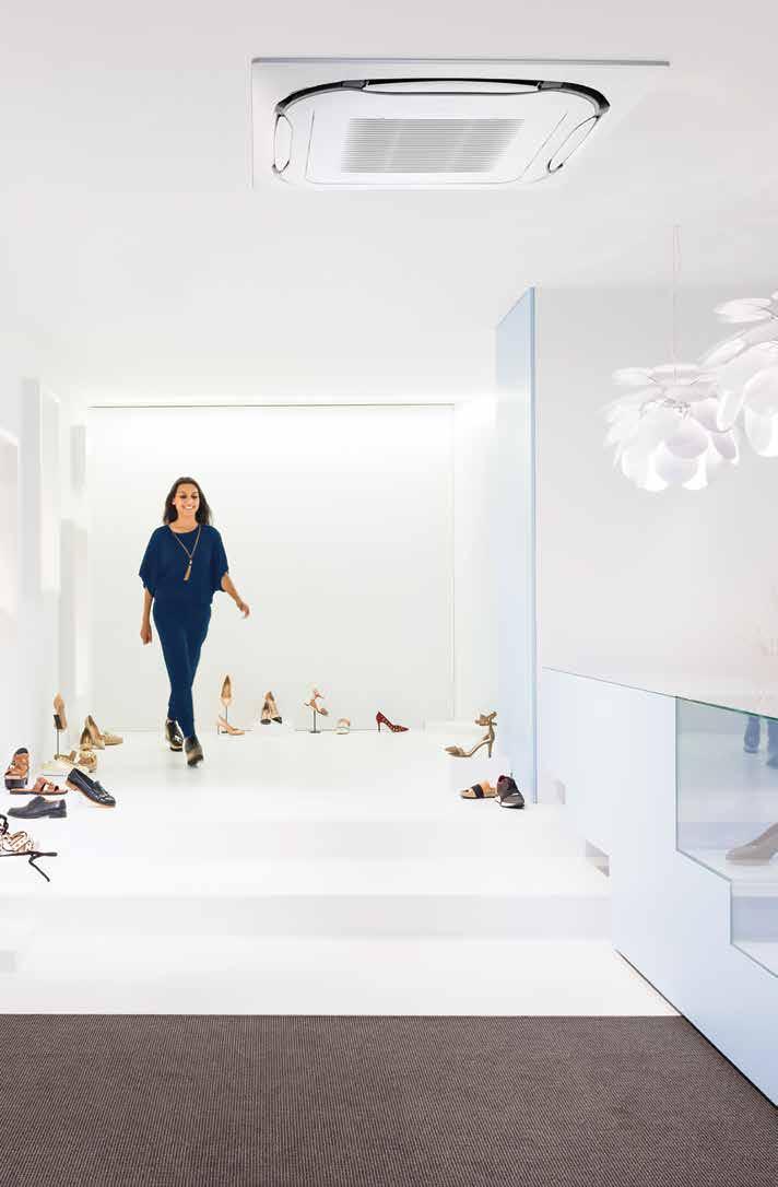
14 "We were very happy to work with Daikin in installing one of the latest fully controllable systems with operational flexibility, which met all our requirements." Retail shop representative Shops Reducing retail costs Open door trading thanks to Biddle air curtains Discreet with limited visual and operating impact Reduces energy usage and costs Worry-free installation User-friendly control In the current commercial environment, retailers are under pressure to reduce both store development and running costs. Legislation adds further financial pressure with different energy-efficient schemes. Therefore affordable, energy-efficient solutions are vital to minimise lifetime costs, while ensuring compliance with the latest regulations. Whatever the site and requirements we can design a system that is economical, has low environmental impact and uses the very latest technology. Our heat pumps extract heat from the outside air even in cold weather to warm the retail space and can be installed either on roof tops or against walls - the ultimate in installation flexibility. And our air curtains solve that problem of comfort loss resulting from exterior doors. Check on DaikinEurope Store & shop "Leading edge design in harmony with the construction and interior design. Architect Offices Efficiency in the workplace Fully flat cassette: Design and genius in one. Cutting the cost of hot water. Fresh air: A healthier office atmosphere. Centralised control: Complete Daikin package for office building management Efficient building and facilities management is key to minimising operational costs. Daikin s customised office solutions give you full control over energy 12 consumption creating the ideal working conditions and minimising environmental impact. Daikin s office air conditioning can be integrated into a whole climate control solution. Heat recovery between components, free cooling ventilation and free hot water production all result in lower running costs and minimum carbon emissions.


15 Total renovation and expansion of the restaurant meant new air conditioning equipment was required. Daikin was the first and only supplier to contact as we had already had good experience in the past! Owner of a highly-rated restaurant Sky Air Intro Restaurants Perfect ambiance for dining Ensures an even temperature distribution to create the perfect dining environment. Heat recovery ventilation keeps the air clean Highly energy efficient Uses intelligent control systems operated from one central location. Nothing should distract diners from enjoying the perfect ambience, and that ambience includes the optimum temperature and ventilation. That is exactly what Daikin s concealed ceiling units deliver through whisper quiet operation and improved comfort from the 3-step air flow control. These turn your customer s restaurant into a comfortable, welcoming environment. And with centralised control and easy scheduling for the entire restaurant system, energy use is minimised to reduce your customer s running costs. A reliable system and guaranteed continuous operation are what count for me. General office manager IT rooms, laboratories and telecom shelters Sky Air for infrastructure cooling Continuous cooling operation. Dedicated infrastructure cooling settings Unique selection method with capacity tables down to -20 C outdoor temperature Enhanced reliability thanks to assymetric combinations (e.g. 125 class indoor class outdoor) Servers, especially racks of servers, generate a great deal of heat and this needs to be removed through continuous cooling. This is achieved through duty rotation between units after a certain period of use to ensure that at any time, one unit is working while the other is available for maintenance. Given the critical importance of continuous cooling for server rooms, the system can be managed via an RTD-10 controller that can monitor and control up to 8 indoor units either directly or via the building management system (RTD-NET). 13
16 Sky Air, from high specification, tailored solutions to primary cooling and heating 14
17 Indoor units Indoor units A wide range of unified indoor units for the use with R-32 and R-410A refrigerant. Products overview 16 Benefits overview 18 Ceiling mounted cassettes 22 FCAHG-G / 25 FCAG-A / 26 FFA-A / 33 Concealed ceiling units 34 FDXM-F3 / 36 FBA-A / 37 FDA-A / 41 FDQ-B 71 ADEQ-C 72 ABQ-C 73 Wall mounted units 42 FAA-A / 42 Ceiling suspended units 46 FHA-A / 46 FUA-A / 50 AHQ-C 80 Floor standing units 52 FVA-A / 52 Concealed floor standing units 55 FNA-A / 55 15
18 Indoor units Product overview Type Model Product name PG Ceiling mounted cassette Concealed ceiling UNIQUE High COP, Round flow cassette UNIQUE Round flow cassette UNIQUE Fully flat cassette FFA-A 33 Slim concealed ceiling unit Concealed ceiling unit with medium ESP NEW Auto cleaning option NEW Multi zoning option NEW Multi zoning option FCAHG-G air discharge for the highest efficiency and comfort --High COP cassette ensures top performance for commercial applications --Auto cleaning function ensures high efficiency --Intelligent sensors save energy and maximize comfort --Flexibility to suit every room layout 360 air discharge for the highest efficiency and comfort --Auto cleaning function ensures high efficiency --Intelligent sensors save energy and maximize comfort FCAG-A Flexibility to suit every room layout --Lowest installation height in the market --27~29 db(a) on low fan speed Unique design in the market that integrates fully flat into the ceiling --Perfect integration in standard architectural ceiling tiles --Blend of iconic design and engineering excellence with a white or silver and white finish --Intelligent sensors save energy and maximize comfort --Flexibility to suit every room layout without changing the location of the unit! --Quietest 600 x 600 cassette on the market Slim design for flexible installation --Compact dimensions enable installation in narrow ceiling voids FDXM-F Medium external static pressure up to 40Pa --Small capacity unit developed for small of well insulated rooms --Auto cleaning function ensures high efficiency and reliability FBA-A Concealed ceiling unit with high ESP FDA-A 41 Concealed ceiling unit with high ESP FDQ-B 71 Slimmest yet most powerfull medium static pressure unit on the market! --Slimmest unit in class, only 245mm --Low operating sound level --Medium external static pressure up to 150Pa facilitates using flexible ducts of varying lengths --Automatic air flow adjustment function measures the air volume and static pressure and adjusts it towards the nominal air flow, guaranteeing comfort ESP up to 200Pa, ideal for large sized buildings --Discretely concealed in the ceiling: only the grilles are visible --Possibility to change ESP via wired remote control allows optimisation of the supply air volume --Flexible installation as the air suction direction can be altered from rear to bottom suction ESP up to 250Pa, Ideal for extra large sized spaces --Blends unobtrusively with any interior décor: only the suction and discharge grilles are visible --Up to 26.4kW in heating mode Concealed ceiling unit ADEQ-C 72 Ideal for residential applications with false ceilings --Energy label up to A --Medium external static pressure up to 150Pa facilitates using flexible ducts of varying lengths --Slimmest unit in class, only 245mm --Exclusively offered for pair applications Wall mounted Ceiling suspended Concealed ceiling unit ABQ-C 73 Wall mounted unit FAA-A Ceiling suspended unit FHA-A UNIQUE 4-way blow ceiling suspended unit FUA-A Ceiling suspended unit AHQ-C 80 Ideal for medium sized shops with false ceilings --Discretely concealed in the ceiling: only the grilles are visible --Best protection against possible water leakage For rooms with no false ceilings nor free floor space --The air is comfortably spread up- and downwards thanks to 5 different discharge angles --Easy maintenance as this can be done from the front of the unit --Easy to install: 100 class is 35% lighter than previous model --Flexible to install: pipe connection can be bottom, left or right For wide rooms with no false ceilings nor free floor space --Ideal for comfortable air flow in wide rooms thanks to Coanda effect --Even rooms with ceilings up to 3.8m can be heated up or cooled down very easily! --Can be mounted in corners or narrow spaces without any problem Unique Daikin unit for high rooms with no false ceilings nor free floor space --Even rooms with ceilings up to 3.5m can be heated up or cooled down very easily! --Flexibility to suit every room layout without changing the location of the unit! --Optimum comfort guaranteed with automatic air flow adjustment to the required load --The air is comfortably spread up- and downwards thanks to 5 different discharge angles For wide rooms with no false ceilings nor free floor space --Guarantees a stable temperature Floor standing Floor standing unit FVA-A Concealed floor standing unit FNA-A 55 For spaces with high ceilings --Ideal solution for commercial spaces with no or narrow false ceilings --Even rooms with very high ceilings can be heated up or cooled down very easily! --Guarantees a stable temperature --Vertical and horizontal outblow Designed to be concealed in walls, only grilles remain visible --Slimmest unit on the market with a depth of only 200mm! --Both window sill or ducted installation are possible thanks to sufficient ESP --Whisper quiet operation allows installation in any location 16
19 Full R-32 Indoor units line up Capacity class Outdoor unit combination RZAG * RZASG * AZAS * Seasonal Smart RZQG * RZQSG * AZQS * RZQ * Indoor units 17
20 Indoor units Benefits overview We care Seasonal efficiency - Smart use of energy Inverter technology Home leave operation Fan only Auto cleaning filter Floor and presence sensor Seasonal efficiency gives a more realistic indication on how efficient air conditioners operate over an entire heating or cooling season. In combination with inverter controlled outdoor units During absence, the indoor temperature can be maintained at a certain level. The air conditioner can be used as fan, blowing air without cooling or heating. The filter automatically cleans itself. Simplicity of upkeep means optimum energy efficiency and maximum comfort without the need for expensive or time-consuming maintenance. The presence sensor directs the air away from any person detected in the room, when the air flow control is on. The floor sensor detects the average floor temperature and ensures an even temperature distribution between ceiling and floor. Comfort Draught prevention When starting to warm up or when the thermostat is off, the air discharge direction is set horizontally and the fan to low speed, to prevent draught. After warming up, air discharge and fan speed are set as desired. Whisper quiet Daikin indoor units are whisper quiet. Also the outdoor units are guaranteed not to disturb the quiet of the neightbourhood. Auto cooling-heating Automatically selects cooling or heating mode to achieve the set temperature. changeover Air treatment Air filter Removes airborne dust particles to ensure a steady supply of clean air. Humidity control Dry programme Allows humidity levels to be reduced without variations in room temperature. Air flow Ceiling soiling prevention Vertical auto swing Fan speed steps A special function prevents air blowing out too long in horizontal position, to prevent ceiling stains. Possibility to select automatic vertical moving of the air discharge louvre, for uniform air flow and temperature distribution. Allows to select up to the given number of fan speed. Individual flap control Individual flap control via the wired remote controller makes it simple to fix the position of each flap individually, to suit any new room configuration. Optional closure kits are available as well. Online controller Can control and monitor the status of a heating system or up to 50 split air conditioning units Remote control & timer Weekly timer Infrared remote control Timer can be set to start operation anytime on a daily or weekly basis Infrared remote control with LCD to start, stop and regulate the air conditioner from a distance. Wired remote control Wired remote control to start, stop and regulate the air conditioner from a distance. Centralised control Centralised control to start, stop and regulate several air conditioners from one central point. Multi zoning NEW Allows up to 6 individual climate zones with one indoor unit Other functions 18 Infrastructure cooling Auto-restart Self-diagnosis Drain pump kit Twin/triple/double twin application Multi model application VRV for residential application Remove in a reliable, efficient and flexible way the heat constantly generated by the IT and server equipment to ensure maximum uptime while offering the best return on investment. The unit restarts automatically at the original settings after power failure. Simplifies maintenance by indicating system faults or operating anomalies. Facilitates condensation draining from the indoor unit. 2, 3 or 4 indoor units can be connected to only 1 outdoor unit. All indoor units operate within the same mode (cooling or heating) from one remote control. Up to 5 indoor units (even different capacities) can be connected to a single outdoor unit. All indoor units can individually be operated within the same mode. Up to 9 indoor units (even different capacities and up to 71 class) can be connected to a single outdoor unit. All indoor units can individually be operated within the same mode.
21 Indoor units Ceiling mounted cassette units Concealed ceiling units Ceiling suspended units 4-Way blow ceiling suspended unit Ceiling suspended units Wall mounted unit Floor standing units FCAHG-G FCAG-A FFA-A FDXM-F3 FBA-A FDA-A FDQ-B ADEQ-C ABQ-C FHA-A FUA-A AHQ-C FAA-A FVA-A FNA-A NEW Indoor units NEW NEW NEW NEW NEW NEW NEW NEW NEW NEW NEW depending on controller optional optional optional optional optional optional optional optional optional standard optional optional optional optional optional optional optional optional optional optional standard optional optional optional optional optional optional NEW optional optional optional optional optional optional optional optional optional optional optional optional optional NEW NEW standard standard standard standard standard optional optional standard optional 19


22 Sky Air FULLY FLAT CASSETTE CONCEALED CEILING UNIT CONCEALED FLOOR STANDING UNIT 4-WAY BLOW CEILING SUSPENDED CASSETTE 20


23 Sky Air Indoor units WALL MOUNTED UNIT CEILING SUSPENDED UNIT AUTO CLEANING CASSETTE WITH FINE MESH FILTER, IDEAL FOR CLOTHING SHOPS 21


24 ARGUE CARDS FCAHG-G/FCAG-A Auto cleaning cassette Why choose a round flow cassette? 360 air discharge for optimum comfort Intelligent sensors for maximum efficiency More energy efficient and user-friendly than any other cassette Running costs are reduced by 50% compared with standard solutions Automatic filter cleaning. Less time is required to maintain the filter: dust can be removed easily with a vacuum cleaner without opening the unit. Finer mesh panel For dust prone areas (i.e. clothing and book shops) a finer mesh panel (BYCQ140DGF9) ensures consistent performance and optimum air distribution Clean ceilings ensured thanks to fine mesh and clean filter BYCQ140DG9 Auto-cleaning panel White with grey louvers BYCQ140DGF9 Auto-cleaning panel with fine mesh filter White with grey louvers Auto-cleaning cassette for maintaining the optimum store atmosphere Dust can be removed easily with a vacuum cleaner without opening the unit. 22 Air distribution with a clean filter Air distribution with a dusty filter
25 References Energy consumption (kwh) 9000 Standard round 8000 Up to 50% savings flow cassette 7000 thanks to 6000 automated cleaning 5000 Auto cleaning cassette Cumulative energy comparison over 12 months July Aug. Sept. Oct. Nov. Dec. Jan. Feb. March April May June July Coral shop, UK Running costs were reduced by up to 50% compared with standard solutions thanks to clean filter Indoor units 360 air discharge for improved comfort Industry-first and proven design. Intelligent sensors improve efficiency and comfort even more The presence sensor adjusts the set point if no one is detected in the room leading to up to 27% savings. It also automatically directs air flow away from any person to avoid draught. presence sensor The infrared floor sensor detects the average floor temperature and ensures even temperature distribution between ceiling and floor to prevent cold feet. Flexible installation Flaps can be individually controlled or closed using the wired remote control, to suit room configuration. Optional closure kits are also available. floor sensor Benefits for the installer Product with unique functions in this market. Less time needed for onsite maintenance. Use the controller to individually open or close any of the four flaps to easily adapt to a changing room layout. Easy set-up of the sensor option to improve comfort and save energy. Benefits for the consultant Product with unique functions in this market. Designed for use in all types and sizes of commercial offices and retail environments. Ideal product for improving BREEAM score/epbd in combination with Sky Air or VRV IV heat pump units. Benefits for the end user Designed for use in all types and sizes of commercial offices and retail environments. Perfect environment conditions: no more draughts or cold feet. Save up to 50% on running costs with the auto-cleaning panel, which also facilitates maintenance. Your customers can save up to 27% on their energy bills thanks to the sensor option. Flexible use of space thanks to individual flap control. Marketing tools Visit the website:
26 24
27 FCAHG-G + RZAG-MV1/MY1 High COP, round flow cassette 360 air discharge for optimum efficiency and comfort High COP cassette ensures top performance, great savings in energy consumption and a comfortable environment for commercial applications Unified indoor unit range for R-32 and R-410A Combining with R-32 Bluevolution technology, reduces environmental impact with 68% compared to R-410A, leads directly to lower energy consumption thanks to its high energy efficiency and has up to lower 16% refrigerant charge Automatic filter cleaning results in higher efficiency & comfort and lower maintenance costs. 2 filters available: standard filter and finer mesh filter (for fine dust applications e.g. clothing shops) Two optional intelligent sensors improve energy efficiency and comfort. Individual flap control: flexibility to suit every room layout without changing the location of the unit! Modern style decoration panel is available in 3 different variations: white (RAL9010) with grey louvers, full white (RAL9010) or auto cleaning panel 5 different fan speeds available for maximum comfort Reduced energy consumption thanks to specially developed small tube heat exchanger, DC fan motor and drain pump Optional fresh air intake Branch duct discharge allows to optimize air distribution in irregular shaped rooms or to supply air to small adjacent rooms RZAG MV1_MY1 FCAHG-G BRC1H51W BRP069A81 Standard drain pump with 675mm lift increases flexibility and installation speed Indoor units Efficiency data FCAHG + RZAG 71G + 71MV1 100G + 100MV1 125G + 125MV1 140G + 140MV1 71G + 71MY1 100G + 100MY1 125G + 125MY1 140G + 140MY1 Cooling capacity Nom. kw Heating capacity Nom. kw Seasonal efficiency (according to EN14825) Cooling Energy efficiency class A++ - A++ - Pdesign kw SEER Annual energy consumption kwh , ,014 Heating (Average climate) Energy efficiency class A++ - A++ - Pdesign kw SCOP/A Annual energy consumption kwh 1,427 2,771 2,942 3,002 1,427 2,771 2,942 3,002 Indoor unit FCAHG 71G 100G 125G 140G 71G 100G 125G 140G Dimensions Unit HeightxWidthxDepth mm 288x840x840 Weight Unit kg 25 Air filter Type Resin net Decoration panel Model BYCQ140DGF9 - auto cleaning panel with fine mesh filter / BYCQ140DG9 - auto cleaning panel / BYCQ140DW - full white / BYCQ140D - white with grey louvers Colour Pure White (RAL 9010) Dimensions HeightxWidthxDepth mm 130x950x950 / 130x950x950 / 50x950x950 / 50x950x950 Weight kg 10.3 / 10.3 / 5.4 / 5.4 Fan Air flow rate Cooling Low/Medium/High m³/min 12.2/16.7/ /25.7/ /26.7/ /27.3/ /16.7/ /25.7/ /26.7/ /27.3/33.5 Heating Low/Medium/High m³/min 12.2/16.7/ /25.7/ /26.7/ /27.3/ /16.7/ /25.7/ /26.7/ /27.3/33.5 Sound power level Cooling dba Heating dba Sound pressure level Cooling Low/High dba 29/36 33/44 35/45 37/45 29/36 33/44 35/45 37/45 Heating Low/High dba 29/36 33/44 35/45 37/45 29/36 33/44 35/45 37/45 Control systems Infrared remote control BRC7FA532F Wired remote control BRC1H51 / BRC1E53A / BRC1E53B / BRC1E53C / BRC1D52 Power supply Phase/Frequency/Voltage Hz/V 1~/50/60/ /220 Outdoor unit RZAG 71MV1 100MV1 125MV1 140MV1 71MY1 100MY1 125MY1 140MY1 Dimensions Unit HeightxWidthxDepth mm 990x940x320 1,430x940x x940x320 1,430x940x320 Weight Unit kg Sound power level Cooling dba Sound pressure level Cooling Nom. dba Heating Nom. dba Operation range Cooling Ambient Min.~Max. CDB -20~52 Heating Ambient Min.~Max. CWB -20~18.0 Refrigerant Type/GWP R-32/675 Charge kg/tco2eq 2.95/ / / /2.53 Piping connections Liquid/Gas mm 9.52/15.9 Piping length OU - IU Max. m System Equivalent m Chargeless m 40 Additional refrigerant charge kg/m See installation manual Level difference IU - OU Max. m 30.0 Power supply Phase/Frequency/Voltage Hz/V 1~/50/ ~/50/ Current - 50Hz Maximum fuse amps (MFA) A (1) BYCQ140D7W1: pure white standard panel with grey louvers; BYCQ140D7W1W: pure white standard panel with white louvers; BYCQ140D7GW1: pure white auto cleaning panel. (2) EER/COP according to Eurovent 2012, for use outside EU only (3) The BYCQ140D7W1W has white insulations. Be informed that formation of dirt on white insulation is visibly stronger and that it is consequently not advised to install the BYCQ140D7W1W decoration panel in environments exposed to concentrations of dirt. (4) MFA is used to select the circuit breaker and the ground fault circuit interrupter (earth leakage circuit breaker). For more detailed information on each combination, please refer to the electrical data drawing. 25
28 FCAG-A + RZAG-MV1/MY1 Round flow cassette 360 air discharge for optimum efficiency and comfort Combination with Sky Air Alpha-series ensures best in class quality, highest efficiency and performance Unified indoor unit range for R-32 and R-410A Combining with R-32 Bluevolution technology, reduces environmental impact with 68% compared to R-410A, leads directly to lower energy consumption thanks to its high energy efficiency and has up to lower 16% refrigerant charge Automatic filter cleaning results in higher efficiency & comfort and lower maintenance costs. 2 filters available: standard filter and finer mesh filter (for fine dust applications e.g. clothing shops) Two optional intelligent sensors improve energy efficiency and comfort. Individual flap control: flexibility to suit every room layout without changing the location of the unit! Modern style decoration panel is available in 3 different variations: white (RAL9010) with grey louvers, full white (RAL9010) or auto cleaning panel 5 different fan speeds available for maximum comfort Reduced energy consumption thanks to specially developed small tube heat exchanger, DC fan motor and drain pump Optional fresh air intake Branch duct discharge allows to optimize air distribution in irregular shaped rooms or to supply air to small adjacent rooms Standard drain pump with 675mm lift increases flexibility and installation speed RZAG MV1_MY1 FCAG-A BRC1H51W BRP069A81 Efficiency data FCAG + RZAG 71A + 71MV1 100A + 100MV1 125A + 125MV1 140A + 140MV1 71A + 71MY1 100A + 100MY1 125A + 125MY1 140A + 140MY1 Cooling capacity Nom. kw Heating capacity Nom. kw Seasonal efficiency (according to EN14825) 26 Cooling Energy efficiency class A++ - A++ - Pdesign kw SEER Annual energy consumption kwh , ,121 Heating (Average climate) Energy efficiency class A+ A++ - A+ A++ - Pdesign kw SCOP/A Annual energy consumption kwh 1,492 2,369 3,071 1,492 2,369 3,071 Indoor unit FCAG 71A 100A 125A 140A 71A 100A 125A 140A Dimensions Unit HeightxWidthxDepth mm 204x840x x840x x840x x840x840 Weight Unit kg Air filter Type Resin net Decoration panel Model BYCQ140DGF9 - auto cleaning panel with fine mesh filter / BYCQ140DG9 - auto cleaning panel / BYCQ140DW - full white / BYCQ140D - white with grey louvers Colour Pure White (RAL 9010) Dimensions HeightxWidthxDepth mm 130x950x950 / 130x950x950 / 50x950x950 / 50x950x950 Weight kg 10.3 / 10.3 / 5.4 / 5.4 Fan Air flow rate Cooling Low/Medium/High m³/min 9.3/12.5/ /17.6/ /19.2/ /12.5/ /17.6/ /19.2/26.0 Heating Low/Medium/High m³/min 9.1/12.1/ /17.6/ /19.2/ /12.1/ /17.6)/ /19.2/26.0 Sound power level Cooling dba Heating dba Sound pressure level Cooling Low/High dba 28/35 29/37 29/41 28/35 29/37 29/41 Heating Low/High dba 28/33 29/37 29/41 28/33 29/37 29/41 Control systems Infrared remote control BRC7FA532F Wired remote control BRC1H51 / BRC1E53A / BRC1E53B / BRC1E53C / BRC1D52 Power supply Phase/Frequency/Voltage Hz/V 1~/50/60/ /220 Outdoor unit RZAG 71MV1 100MV1 125MV1 140MV1 71MY1 100MY1 125MY1 140MY1 Dimensions Unit HeightxWidthxDepth mm 990x940x320 1,430x940x x940x320 1,430x940x320 Weight Unit kg Sound power level Cooling dba Sound pressure level Cooling Nom. dba Heating Nom. dba Operation range Cooling Ambient Min.~Max. CDB -20~52-15~46-20~52 Heating Ambient Min.~Max. CWB -20~ ~ ~18.0 Refrigerant Type/GWP R-32/675 Charge kg/tco2eq 2.95/ / / / /2.53 Piping connections Liquid/Gas mm 9.52/15.9 Piping length OU - IU Max. m System Equivalent m Chargeless m Additional refrigerant charge kg/m See installation manual Level difference IU - OU Max. m 30.0 Power supply Phase/Frequency/Voltage Hz/V 1~/50/ ~/50/ Current - 50Hz Maximum fuse amps (MFA) A (1) BYCQ140D7W1: pure white standard panel with grey louvers; BYCQ140D7W1W: pure white standard panel with white louvers; BYCQ140D7GW1: pure white auto cleaning panel. (2) EER/COP according to Eurovent 2012, for use outside EU only (3) The BYCQ140D7W1W has white insulations. Be informed that formation of dirt on white insulation is visibly stronger and that it is consequently not advised to install the BYCQ140D7W1W decoration panel in environments exposed to concentrations of dirt. (4) MFA is used to select the circuit breaker and the ground fault circuit interrupter (earth leakage circuit breaker). For more detailed information on each combination, please refer to the electrical data drawing.
29 FCAG-A + RZASG-MV1/MY1 Round flow cassette 360 air discharge for optimum efficiency and comfort Combination with Sky Air Advance-series ensures good value for money for all types of commercial applications Unified indoor unit range for R-32 and R-410A Combining with R-32 Bluevolution technology, reduces environmental impact with 68% compared to R-410A, leads directly to lower energy consumption thanks to its high energy efficiency and has up to lower 16% refrigerant charge Automatic filter cleaning results in higher efficiency & comfort and lower maintenance costs. 2 filters available: standard filter and finer mesh filter (for fine dust applications e.g. clothing shops) Two optional intelligent sensors improve energy efficiency and comfort Individual flap control: flexibility to suit every room layout without changing the location of the unit! Modern style decoration panel is available in 3 different variations: white (RAL9010) with grey louvers, full white (RAL9010) or auto cleaning panel RZASG MV1_MY1 FCAG-A BRC1H51W BRP069A81 Indoor units Efficiency data FCAG + RZASG 71A + 71MV1 100A + 100MV1 125A + 125MV1 140A + 140MV1 100A + 100MY1 125A + 125MY1 140A + 140MY1 Cooling capacity Nom. kw Heating capacity Nom. kw Seasonal efficiency (according to EN14825) Cooling Energy efficiency class A++ - A++ - Pdesign kw SEER Annual energy consumption kwh ,261 1, ,261 1,231 Heating (Average climate) Energy efficiency class A A+ - A+ - Pdesign kw SCOP/A Annual energy consumption kwh 1,575 2,016 2,074 2,534 2,016 2,074 2,534 Indoor unit FCAG 71A 100A 125A 140A 100A 125A 140A Dimensions Unit HeightxWidthxDepth mm 204x840x x840x840 Weight Unit kg Air filter Type Resin net Decoration panel Model BYCQ140DGF9 - auto cleaning panel with fine mesh filter / BYCQ140DG9 - auto cleaning panel / BYCQ140DW - full white / BYCQ140D - white with grey louvers Colour Pure White (RAL 9010) Dimensions HeightxWidthxDepth mm 130x950x950 / 130x950x950 / 50x950x950 / 50x950x950 Weight kg 10.3 / 10.3 / 5.4 / 5.4 Fan Air flow rate Cooling Low/Medium/High m³/min 9.3/12.5/ /17.6/ /19.2/ /17.6/ /19.2/26.0 Heating Low/Medium/High m³/min 9.1/12.1/ /17.6/ /19.2/ /17.6/ /19.2/26.0 Sound power level Cooling dba Heating dba Sound pressure level Cooling Low/High dba 28/35 29/37 29/41 29/37 29/41 Heating Low/High dba 28/33 29/37 29/41 29/37 29/41 Control systems Infrared remote control BRC7FA532F Wired remote control BRC1H51 / BRC1E53A / BRC1E53B / BRC1E53C / BRC1D52 Power supply Phase/Frequency/Voltage Hz/V 1~/50/60/ /220 Outdoor unit RZASG 71MV1 100MV1 125MV1 140MV1 100MY1 125MY1 140MY1 Dimensions Unit HeightxWidthxDepth mm 770x900x x940x320 Weight Unit kg Sound power level Cooling dba Sound pressure level Cooling Nom. dba Heating Nom. dba Operation range Cooling Ambient Min.~Max. CDB -15~46 Heating Ambient Min.~Max. CWB -15~15.5 Refrigerant Type/GWP R-32/675 Charge kg/tco2eq 2.45/ / / / /1.96 Piping connections Liquid/Gas mm 9.52/15.9 Piping length OU - IU Max. m 50 System Equivalent m 70 Chargeless m 30 Additional refrigerant charge kg/m See installation manual Level difference IU - OU Max. m 30.0 Power supply Phase/Frequency/Voltage Hz/V 1~/50/ ~/50/ Current - 50Hz Maximum fuse amps (MFA) A (1) BYCQ140D7W1: pure white standard panel with grey louvers; BYCQ140D7W1W: pure white standard panel with white louvers; BYCQ140D7GW1: pure white auto cleaning panel. (2) EER/COP according to Eurovent 2012, for use outside EU only (3) The BYCQ140D7W1W has white insulations. Be informed that formation of dirt on white insulation is visibly stronger and that it is consequently not advised to install the BYCQ140D7W1W decoration panel in environments exposed to concentrations of dirt. (4) MFA is used to select the circuit breaker and the ground fault circuit interrupter (earth leakage circuit breaker). For more detailed information on each combination, please refer to the electrical data drawing. 27
30 FCAG-A + AZAS-MV1/MY1 Round flow cassette 360 air discharge for optimum efficiency and comfort Ideal solution for small businesses and shops Unified indoor unit range for R-32 and R-410A Combining with R-32 Bluevolution technology, reduces environmental impact with 68% compared to R-410A, leads directly to lower energy consumption thanks to its high energy efficiency and has up to lower 16% refrigerant charge Automatic filter cleaning results in higher efficiency & comfort and lower maintenance costs. 2 filters available: standard filter and finer mesh filter (for fine dust applications e.g. clothing shops) Two optional intelligent sensors improve energy efficiency and comfort Individual flap control: flexibility to suit every room layout without changing the location of the unit! Modern style decoration panel is available in 3 different variations: white (RAL9010) with grey louvers, full white (RAL9010) or auto cleaning panel AZAS71MV1 FCAG-A BRC1H51W BRP069A81 Efficiency data FCAG + AZAS 71A + 71MV1 100A + 100MV1 125A + 125MV1 140A + 140MV1 100A + 100MY1 125A + 125MY1 140A + 140MY1 Cooling capacity Nom. kw Heating capacity Nom. kw Seasonal efficiency (according to EN14825) 28 Cooling Energy efficiency class A+ - A+ - Pdesign kw SEER Annual energy consumption kwh ,345 1, ,345 1,300 Heating (Average climate) Energy efficiency class A - A - Pdesign kw SCOP/A Annual energy consumption kwh 1,575 2,182 2,211 2,534 2,182 2,211 2,534 Indoor unit FCAG 71A 100A 125A 140A 100A 125A 140A Dimensions Unit HeightxWidthxDepth mm 204x840x x840x840 Weight Unit kg Air filter Type Resin net Decoration panel Model BYCQ140DGF9 - auto cleaning panel with fine mesh filter / BYCQ140DG9 - auto cleaning panel / BYCQ140DW - full white / BYCQ140D - white with grey louvers Colour Pure White (RAL 9010) Dimensions HeightxWidthxDepth mm 130x950x950 / 130x950x950 / 50x950x950 / 50x950x950 Weight kg 10.3/5.4/10.3/5.4 Fan Air flow rate Cooling Low/Medium/High m³/min 9.3/12.5/ /17.6/ /19.2/ /17.6/ /19.2 (0.000)/26.0 Heating Low/Medium/High m³/min 9.1/12.1/ /17.6/ /19.2/ /17.6/ /19.2 (0.000)/26.0 Sound power level Cooling dba Heating dba Sound pressure level Cooling Low/High dba 28/35 29/37 29/41 29/37 29/41 Heating Low/High dba 28/33 29/37 29/41 29/37 29/41 Control systems Infrared remote control BRC7FA532F Wired remote control BRC1H51 / BRC1E53A / BRC1E53B / BRC1E53C / BRC1D52 Power supply Phase/Frequency/Voltage Hz/V 1~/50/60/ /220 Outdoor unit AZAS 71MV1 100MV1 125MV1 140MV1 100MY1 125MY1 140MY1 Dimensions Unit HeightxWidthxDepth mm 770x900x x940x320 Weight Unit kg Sound power level Cooling dba Sound pressure level Cooling Nom. dba Heating Nom. dba Operation range Cooling Ambient Min.~Max. CDB -5~46 Heating Ambient Min.~Max. CWB -15~15.5 Refrigerant Type/GWP R-32/675 Charge kg/tco2eq 2.45/ / / / /1.96 Piping connections Liquid/Gas mm 9.52/15.9 Piping length OU - IU Max. m 30 System Equivalent m 50 Chargeless m 30 Additional refrigerant charge kg/m See installation manual Level difference IU - OU Max. m 30.0 Power supply Phase/Frequency/Voltage Hz/V 1~/50/ ~/50/ Current - 50Hz Maximum fuse amps (MFA) A (1) BYCQ140D7W1: pure white standard panel with grey louvers; BYCQ140D7W1W: pure white standard panel with white louvers; BYCQ140D7GW1: pure white auto cleaning panel. (2) EER/COP according to Eurovent 2012, for use outside EU only (3) The BYCQ140D7W1W has white insulations. Be informed that formation of dirt on white insulation is visibly stronger and that it is consequently not advised to install the BYCQ140D7W1W decoration panel in environments exposed to concentrations of dirt. (4) MFA is used to select the circuit breaker and the ground fault circuit interrupter (earth leakage circuit breaker). For more detailed information on each combination, please refer to the electrical data drawing.
31 FCAG-A + RXM-M9 Split Round flow cassette 360 air discharge for optimum efficiency and comfort Combination with split outdoor units is ideal for small retail, offices or residential applications Unified indoor unit range for R-32 and R-410A Combining with R-32 Bluevolution technology, reduces environmental impact with 68% compared to R-410A, leads directly to lower energy consumption thanks to its high energy efficiency and has up to lower 16% refrigerant charge Automatic filter cleaning results in higher efficiency & comfort and lower maintenance costs. 2 filters available: standard filter and finer mesh filter (for fine dust applications e.g. clothing shops) Two optional intelligent sensors improve energy efficiency and comfort Individual flap control: flexibility to suit every room layout without changing the location of the unit! Lowest installation height in the market: 214mm Modern style decoration panel is available in 3 different variations: white (RAL9010) with grey louvers, full white (RAL9010) or auto cleaning panel RXM20-35M9 FCAG-A BRC1H51W BRP069A81 Indoor units Efficiency data FCAG + RXM 35A + 35M9 50A + 50M9 60A + 60M9 Cooling capacity Nom. kw Heating capacity Nom. kw Power input Cooling Nom. kw Heating Nom. kw Seasonal efficiency (according to EN14825) Cooling Energy efficiency class A++ Pdesign kw SEER Annual energy consumption kwh Heating (Average climate) Energy efficiency class A++ A+ Pdesign kw SCOP/A Annual energy consumption kwh 948 1,419 1,569 Indoor unit FCAG 35A 50A 60A Dimensions Unit HeightxWidthxDepth mm 204x840x840 Weight Unit kg Air filter Type Resin net Decoration panel Model BYCQ140DGF9 - auto cleaning panel with fine mesh filter / BYCQ140DG9 - auto cleaning panel / BYCQ140DW - full white / BYCQ140D - white with grey louvers Colour Pure White (RAL 9010) Dimensions HeightxWidthxDepth mm 130x950x950 / 130x950x950 / 50x950x950 / 50x950x950 Weight kg 10.3 / 10.3 / 5.4 / 5.4 Fan Air flow rate Cooling Low/Medium/High m³/min 8.7/10.6/ /10.7/ /11.2/13.6 Heating Low/Medium/High m³/min 9.3/11.6/ /10.7/ /11.2/13.6 Sound power level Cooling dba Heating dba Sound pressure level Cooling Low/High dba 27/31 28/33 Heating Low/High dba 27/31 28/33 Control systems Infrared remote control BRC7FA532F Wired remote control BRC1H51 / BRC1E53A / BRC1E53B / BRC1E53C / BRC1D52 Power supply Phase/Frequency/Voltage Hz/V 1~/50/60/ /220 Outdoor unit RXM 35M9 50M9 60M9 Dimensions Unit HeightxWidthxDepth mm 550x765x x825x300 Weight Unit kg Sound power level Cooling dba Heating dba Operation range Cooling Ambient Min.~Max. CDB -10~46 Heating Ambient Min.~Max. CWB -15~18 Refrigerant Type R-32 GWP Charge kg/tco2eq 0.76/ / /0.98 Piping connections Liquid OD mm 6,35 6,4 Gas OD mm Piping length OU - IU Max. m Additional refrigerant charge kg/m 0.02 (for piping length exceeding 10m) Level difference IU - OU Max. m 20.0 Power supply Phase/Frequency/Voltage Hz/V 1~/50/ Current - 50Hz Maximum fuse amps (MFA) A (1) EER/COP according to Eurovent 2012, for use outside EU only (2) BYCQ140D7W1: pure white standard panel with grey louvers; BYCQ140D7W1W: pure white standard panel with white louvers; BYCQ140D7GW1: pure white auto cleaning panel. (3) The BYCQ140D7W1W has white insulations. Be informed that formation of dirt on white insulation is visibly stronger and that it is consequently not advised to install the BYCQ140D7W1W decoration panel in environments exposed to concentrations of dirt. (4) MFA is used to select the circuit breaker and the ground fault circuit interrupter (earth leakage circuit breaker). For more detailed information on each combination, please refer to the electrical data drawing. 29

32 ARGUE CARDS Fully Flat Cassette Design & Genius in one Why choose fully flat cassette Unique design in the market that integrates fully flat into the ceiling Advanced technology and top efficiency combined Most quiet cassette available on the market Benefits for the installer Unique product in the market! Most quiet unit (25dBA) The user-friendly remote control, available in several languages, enables the easy set-up of sensor option and control of the individual flap position Meeting European design taste. FFA-A Benefits for the consultant Unique product in the market! interior design Blends seamlessly in any modern office Ideal product to improve BREEAM score/epbd in combination with Sky Air (FFA-A) or VRV IV heat pump units (FXZQ-A). Benefits for the end user Engineering excellence and unique design in one Most quiet unit (25dBA) Save up to 27% on your energy bill thanks Perfect working conditions: no more cold draughts to the optional sensors Flexible usage of space and suits any room configuration thanks to individual flap control User-friendly remote control, available in several languages. Choice between grey or white panel 30

.")


33 Indoor units Unique design Designed by a European design office to fully meet the European taste. Fully flat into the ceiling, leaving only 8mm. Fully integrated in the one ceiling tile, enabling lights, speakers and sprinklers to be installed in adjoining ceiling tiles. Decoration panel available in 2 colours (white and white-silver). Differentiating in technology Optional presence sensor When the room is empty, it can adjust the set temperature or switch off the unit saving energy. When people are detected, the direction of the airflow is adapted to avoid cold draughts being directed towards occupants. Optional floor sensor Detects the temperature difference and re-directs the airflow to ensure even temperature distribution. Top efficiency * Seasonal efficiency labels up to A + + When the room is empty, the sensor option can adjust the set temperature or switch off the unit saving up to 27% energy. * for FFA25,35A in combination with RXM25,35M9 Other benefits Individual flap control: easily control one or more flaps via the wired remote controller (BRC1E*) when rearranging the room. When fully closing or blocking the flaps, the option Sealing member of air discharge outlet is needed. Most silent cassette in the market (25dBA), important for office applications. Marketing tools

34 32
35 FFA-A + RXM-M9 Split Fully flat cassette Unique design in the market that integrates fully flat into the ceiling Fully flat integration in standard architectural ceiling tiles, leaving only 8mm Remarkable blend of iconic design and engineering excellence with an elegant finish in white or a combination of silver and white Unified indoor unit range for R-32 and R-410A Combining with R-32 Bluevolution technology, reduces environmental impact with 68% compared to R-410A, leads directly to lower energy consumption thanks to its high energy efficiency and has up to lower 16% refrigerant charge Two optional intelligent sensors improve energy efficiency and comfort FFA-A Indoor units Individual flap control: flexibility to suit every room layout without changing the location of the unit! Reduced energy consumption thanks to specially developed small tube heat exchanger, DC fan motor and drain pump Optional fresh air intake Branch duct discharge allows to optimize air distribution in irregular shaped rooms or to supply air to small adjacent rooms Standard drain pump with 630mm lift increases flexibility and installation speed RXM20-35M9 BRC1H51W BRP069A81 Efficiency data FFA + RXM 25A + 25M9 35A + 35M9 50A + 50M9 60A + 60M9 Cooling capacity Nom. kw Heating capacity Nom. kw Power input Cooling Nom. kw Heating Nom. kw Seasonal efficiency (according to EN14825) Cooling Energy efficiency class A++ A+ Pdesign kw SEER Annual energy consumption kwh Heating (Average climate) Energy efficiency class A+ A A+ Pdesign kw SCOP/A Annual energy consumption kwh 762 1,058 1,377 1,372 Indoor unit FFA 25A 35A 50A 60A Dimensions Unit HeightxWidthxDepth mm 260x575x575 Weight Unit kg Air filter Type Resin net Decoration panel Model BYFQ60C2W1W/BYFQ60C2W1S/BYFQ60B2W1/BYFQ60B3W1 Colour White (N9.5)/SILVER/White (RAL9010)/WHITE (RAL9010) Dimensions HeightxWidthxDepth mm 46x620x620 / 46x620x620 / 55x700x700 / 55x700x700 Weight kg 2.8/2.8/2.7/2.7 Fan Air flow rate Cooling Low/Medium/High m³/min 6.5/8.0/ /8.5/ /10.0/ /12.5/14.5 Heating Low/Medium/High m³/min 6.5/8.0/ /8.5/ /10.0/ /12.5/14.5 Sound power level Cooling dba Sound pressure level Cooling Low/High dba 25.0/ / / /43.0 Heating Low/High dba 25.0/ / / /43.0 Control systems Infrared remote control BRC7EB530W (standard panel) / BRC7F530W (white panel) / BRC7F530S (grey panel) Wired remote control BRC1H51 / BRC1E53A / BRC1E53B / BRC1E53C / BRC1D52 Power supply Phase/Frequency/Voltage Hz/V 1~/50/ Outdoor unit RXM 25M9 35M9 50M9 60M9 Dimensions Unit HeightxWidthxDepth mm 550x765x x825x300 Weight Unit kg Sound power level Cooling dba Heating dba Operation range Cooling Ambient Min.~Max. CDB -10~46 Heating Ambient Min.~Max. CWB -15~18 Refrigerant Type R-32 GWP Charge kg/tco2eq 0.76/ / /0.98 Piping connections Liquid OD mm 6,35 6,4 Gas OD mm Piping length OU - IU Max. m System Chargeless m Additional refrigerant charge kg/m 0.02 (for piping length exceeding 10m) Level difference IU - OU Max. m 20.0 Power supply Phase/Frequency/Voltage Hz/V 1~/50/ Current - 50Hz Maximum fuse amps (MFA) A (1) EER/COP according to Eurovent 2012, for use outside EU only. (2) MFA is used to select the circuit breaker and the ground fault circuit interrupter (earth leakage circuit breaker). For more detailed information on each combination, please refer to the electrical data drawing. 33

36 ARGUE CARDS Auto cleaning filter for concealed ceiling units The unique automatic cleaning filter achieves higher efficiency and comfort with lower maintenance costs Reduce running costs Automatic filter cleaning ensures low maintenance costs because the filter is always clean airflow direction Gradual loss of efficiency due to dirty filter Efficiency profile change for duct indoor unit during operation 100% Up to 20% Energy saved thanks to automatic filter cleaning UNIQUE Patents pending 0% start 6 months 12 months Minimal time required for filter cleaning The dust box can be emptied with a vacuum cleaner for fast and easy cleaning No more dirty ceilings Improved indoor air quality Optimum airflow eliminates draft and insulates sound Superb reliability Prevents clogged filters for seamless operation Unique technology Unique and innovative filter technology inspired by the Daikin auto cleaning cassette How does it work? 1 Scheduled automatic filter cleaning 2 Dust collects in a dust box that s integrated into the unit 3 The dust can easily be removed with a vacuum cleaner Combination table Specifications Split / Sky Air VRV FDXM-F3 FXDQ-A BAE20A62 BAE20A82 BAE20A102 BAE20A62 BAE20A82 BAE20A102 Heigth (mm) 212 Width (mm) Width (mm) (incl. hanger bracket) Depth (mm)

37 ARGUE CARDS Multi zoning kit for concealed ceiling units Indoor units The multi-zoning system is a room-by-room controller. It is fitted with motorised dampers, which immediately adapt using Daikin ducted solutions. This system supports control of up to 8 zones via a centralised thermostat located in the main room and individual thermostats for each of the zones. Benefits Increased comfort Increases comfort levels by allowing more individual zone control --Up to 8 individual zones can be served thanks to separate modulating dampers --Individual thermostat for room-by-room or zone-by-zone control Easy to install Automatic air flow adjustment according to the demand Easy to install, integrates with the Daikin indoor units and system controls Time saving as plenum comes fully pre-assembled with dampers, and control boards Reduces the amount of refrigerant required in the installation Plug and play plenum Concealed ceiling unit How does it work? 20 C Individual zone thermostats Blueface - Airzone Main Thermostat Color graphic interface for controlling zones Wired communication 21 C Airzone Zone Thermostat Graphic interface with low-energy e-ink screen for controlling zones Radio communication 19 C Zoning box: fully pre-assembled plenum with dampers Airzone Zone Thermostat Thermostat with buttons for controlling the temperature Radio communication Motorized dampers Electronic control panel AZCE6BLUEFACECB AZCE6THINKRB AZCE6LITERB Compatibility Number of motorised dampers Standard Ceiling Void Compact Ceiling Void Reference Dimensions H x L x D (mm) FDXM-F3 FBA-A ADEQ-C FXDQ-A3 FXSQ-A AZEZ6DAIST07XS2 930 x 300 x 454 AZEZ6DAIST07S2 AZEZ6DAIST07XS3 930 x 300 x 454 AZEZ6DAIST07S3 AZEZ6DAIST07S4 930 x 300 x 454 AZEZ6DAIST07M4 1,140 x 300 x 454 AZEZ6DAIST07M5 1,425 x 300 x 454 AZEZ6DAIST07L5 AZEZ6DAIST07M6 1,638 x 300 x 454 AZEZ6DAIST07L6 AZEZ6DAIST07L7 1,425 x 515 x 454 AZEZ6DAIST07XL7 AZEZ6DAIST07L8 1,425 x 515 x 454 AZEZ6DAIST07XL8 2 AZEZ6DAISL01S2 720 x 210 x AZEZ6DAISL01S3 720 x 210 x AZEZ6DAISL01M4 930 x 210 x AZEZ6DAISL01L5 1,140 x 210 x
38 FDXM-F3 + RXM-M9 Split Concealed ceiling unit rear suction Compact concealed ceiling unit, with a height of only 200mm Invisible unit as the unit is concealed in the ceiling: only the suction and discharge grilles are visible Compact dimensions, can easily be mounted in a ceiling void of only 240mm outblow FDXM-F3 bottom suction Medium external static pressure up to 40Pa facilitates unit use with flexible ducts of varying lengths Unified indoor unit range for R-32 and R-410A NEW Auto cleaning filter option ensures maximum efficiency, comfort and reliability by regular filter cleaning NEW Multi zoning kit allows multiple individually-controlled climate zones to be served by one indoor unit Online controller (optional): control your indoor from any location with an app, via your local network or internet and keep an overview on your energy consumption Low energy consumption thanks to DC fan motor RXM20-35M9 BRC1H51W BRP069A81 NEW with auto cleaning and multi zoning option Efficiency data FDXM + RXM 25F3 + 25M9 35F3 + 35M9 50F3 + 50M9 60F3 + 60M9 Cooling capacity Nom. kw Heating capacity Nom. kw Power input Cooling Nom. kw Heating Nom. kw Seasonal efficiency (according to EN14825) 36 Cooling Energy efficiency class A+ A A+ A Pdesign kw SEER Annual energy consumption kwh Heating (Average climate) Energy efficiency class A+ A Pdesign kw SCOP/A Annual energy consumption kwh 858 1,046 1,424 1,693 Indoor unit FDXM 25F3 35F3 50F3 60F3 Dimensions Unit HeightxWidthxDepth mm 200x750x x1,150x620 Weight Unit kg Air filter Type Removable / washable Fan Air flow rate Cooling Low/Medium/High m³/min 7.3/8.0/ /14.6/ /14.8/16.0 Heating Low/Medium/High m³/min 7.3/8.0/ /14.6/ /14.8/16.0 External static pressure Nom. Pa Sound power level Cooling dba Heating dba Sound pressure level Cooling Low/High dba 27/35 30/38 Heating Low/High dba 27/35 30/38 Power supply Phase/Frequency/Voltage Hz/V 1~/50/ Outdoor unit RXM 25M9 35M9 50M9 60M9 Dimensions Unit HeightxWidthxDepth mm 550x765x x825x300 Weight Unit kg Sound power level Cooling dba Heating dba Operation range Cooling Ambient Min.~Max. CDB -10~46 Heating Ambient Min.~Max. CWB -15~18 Refrigerant Type R-32 GWP Charge kg/tco2eq 0.76/ / /0.98 Piping connections Liquid OD mm 6,35 6,4 Gas OD mm Piping length OU - IU Max. m Additional refrigerant charge kg/m 0.02 (for piping length exceeding 10m) Level difference IU - OU Max. m 20.0 Power supply Phase/Frequency/Voltage Hz/V 1~/50/ Current - 50Hz Maximum fuse amps (MFA) A (1) EER/COP according to Eurovent 2012, for use outside EU only, (2) MFA is used to select the circuit breaker and the ground fault circuit interrupter(earth leakage circuit breaker). For more detailed information on each combination, please refer to the electrical data drawing.
39 FBA-A + RZAG-MV1/MY1 Concealed ceiling unit with medium ESP Slimmest yet most powerful medium static pressure unit on the market Combination with Sky Air Alpha-series ensures best in class quality, highest efficiency and performace Slimmest unit in class, only 245mm (300mm built-in height) and therefore narrow ceiling voids are no longer a challenge outblow FBA-A bottom suction rear suction Indoor units Low operation sound level down to 25dBA Medium external static pressure up to 150Pa facilitates using flexible ducts of varying lengths Unified indoor unit can be combined with R-32 and R-410A outdoor units, symplifying stock Combining with R-32 Bluevolution technology, reduces environmental impact with 68% compared to R-410A, leads directly to lower energy consumption thanks to its high energy efficiency and has up to lower 16% refrigerant charge NEW Possibility to change ESP via wired remote control allows optimisation of the supply air volume Discretely concealed in the ceiling: only the suction and discharge grilles are visible Multi zoning kit allows multiple individually-controlled climate RZAG MV1_MY1 BRC1H51W BRP069A81 NEW with multi zoning option zones to be served by one indoor unit Reduced energy consumption thanks to specially developed DC fan motor Optional fresh air intake Flexible installation: air suction direction can be altered from rear to bottom suction and choice between free use or connection to optional suction grilles Standard built-in drain pump with 625mm lift increases flexibility and installation speed Efficiency data FBA + RZAG 71A + 71MV1 100A + 100MV1 125A + 125MV1 140A + 140MV1 71A + 71MY1 100A + 100MY1 125A + 125MY1 140A + 140MY1 Cooling capacity Nom. kw Heating capacity Nom. kw Seasonal efficiency (according to EN14825) Cooling Energy efficiency class A++ - A++ - Pdesign kw SEER Annual energy consumption kwh ,173 1, ,173 1,252 Heating (Average climate) Energy efficiency class A+ - A+ - Pdesign kw SCOP/A Annual energy consumption kwh 1,566 2,505 3,235 3,243 1,566 2,505 3,235 3,243 Indoor unit FBA 71A 100A 125A 140A 71A 100A 125A 140A Dimensions Unit HeightxWidthxDepth mm 245x1,000x x1,400x x1,000x x1,400x800 Weight Unit kg Air filter Type Resin net Fan Air flow rate Cooling Low/Medium/High m³/min 12.5/15.0/ /26.0/ /29.0/ /15.0/ /26.0/ /29.0/34.0 Heating Low/Medium/High m³/min 12.5/15.0/ /26.0/ /29.0/ /15.0/ /26.0/ /29.0/34.0 External static pressure Nom./High Pa 30/150 40/150 50/150 30/150 40/150 50/150 Sound power level Cooling dba Sound pressure level Cooling Low/High dba 25.0/ / / / / /37.0 Heating Low/High dba 25.0/ / / / / /38.0 Control systems Infrared remote control BRC4C65 / BRC4C66 Wired remote control BRC1H51 / BRC1E53A / BRC1E53B / BRC1E53C / BRC1D52 Power supply Phase/Frequency/Voltage Hz/V 1~/50/60/ /220 Outdoor unit RZAG 71MV1 100MV1 125MV1 140MV1 71MY1 100MY1 125MY1 140MY1 Dimensions Unit HeightxWidthxDepth mm 990x940x320 1,430x940x x940x320 1,430x940x320 Weight Unit kg Sound power level Cooling dba Sound pressure level Cooling Nom. dba Heating Nom. dba Operation range Cooling Ambient Min.~Max. CDB -20~52 Heating Ambient Min.~Max. CWB -20~18.0 Refrigerant Type/GWP R-32/675 Charge kg/tco2eq 2.95/ / / /2.53 Piping connections Liquid/Gas mm 9.52/15.9 Piping length OU - IU Max. m System Equivalent m Chargeless m 40 Additional refrigerant charge kg/m See installation manual Level difference IU - OU Max. m 30.0 Power supply Phase/Frequency/Voltage Hz/V 1~/50/ ~/50/ Current - 50Hz Maximum fuse amps (MFA) A (1) EER/COP according to Eurovent 2012, for use outside EU only (2) MFA is used to select the circuit breaker and the ground fault circuit interrupter (earth leakage circuit breaker). For more detailed information on each combination, please refer to the electrical data drawing. 37
40 FBA-A + RZASG-MV1/MY1 Concealed ceiling unit with medium ESP Slimmest yet most powerful medium static pressure unit on the market outblow NEW Combination with Sky Air Advance-series ensures good value for money for all types of commercial applications Slimmest unit in class, only 245mm (300mm built-in height) Low operation sound level down to 25dBA Medium external static pressure up to 150Pa facilitates using flexible ducts of varying lengths Unified indoor unit can be combined with R-32 and R-410A outdoor units, symplifying stock Combining with R-32 Bluevolution technology, reduces environmental impact with 68% compared to R-410A Possibility to change ESP via wired remote control allows optimisation of the supply air volume Discretely concealed in the ceiling: only the suction and discharge grilles are visible Multi zoning kit allows multiple individually-controlled climate zones to be served by one indoor unit RZASG MV1_MY1 FBA-A bottom suction BRC1H51W BRP069A81 rear suction NEW with multi zoning option Optimised supply air volume Automatically selects the most appropriate fan curve to achieve the units nominal air flow within ±10% Why? After installation the real ducting will frequently differ from the initially calculated air flow resistance the real air flow may be much lower or higher than nominal, leading to a lack of capacity or uncomfortable air temperature Automatic Airflow Adjustment function will adapt the unit s fan speed to any ducting automatically (10 or more fan curves are available on every model), making installation much faster External static pressure (Pa) Fan characteristic curves Duct resistance curves Air flow (rated) Air flow (actual) Air flow (with automatic adjustment) ±10% Air flow (m 3 /min) Efficiency data FBA + RZASG 71A + 71MV1 100A + 100MV1 125A + 125MV1 140A + 140MV1 100A + 100MY1 125A + 125MY1 140A + 140MY1 Cooling capacity Nom. kw Heating capacity Nom. kw Seasonal efficiency (according to EN14825) 38 Cooling Energy efficiency class A++ A+ - A+ - Pdesign kw SEER Annual energy consumption kwh ,378 1, ,378 1,384 Heating (Average climate) Energy efficiency class A+ A - A - Pdesign kw SCOP/A Annual energy consumption kwh 1,571 2,182 2,314 2,836 2,182 2,314 2,836 Indoor unit FBA 71A 100A 125A 140A 100A 125A 140A Dimensions Unit HeightxWidthxDepth mm 245x1,000x x1,400x800 Weight Unit kg Air filter Type Resin net Fan Air flow rate Cooling Low/Medium/High m³/min 12.5/15.0/ /26.0/ /29.0/ /26.0/ /29.0/34.0 Heating Low/Medium/High m³/min 12.5/15.0/ /26.0/ /29.0/ /26.0/ /29.0/34.0 External static pressure Nom./High Pa 30/150 40/150 50/150 40/150 50/150 Sound power level Cooling dba Sound pressure level Cooling Low/High dba 25.0/ / / / /37.0 Heating Low/High dba 25.0/ / / / /38.0 Control systems Infrared remote control BRC4C65 / BRC4C66 Wired remote control BRC1H51 / BRC1E53A / BRC1E53B / BRC1E53C / BRC1D52 Power supply Phase/Frequency/Voltage Hz/V 1~/50/60/ /220 Outdoor unit RZASG 71MV1 100MV1 125MV1 140MV1 100MY1 125MY1 140MY1 Dimensions Unit HeightxWidthxDepth mm 770x900x x940x320 Weight Unit kg Sound power level Cooling dba Sound pressure level Cooling Nom. dba Heating Nom. dba Operation range Cooling Ambient Min.~Max. CDB -15~46 Heating Ambient Min.~Max. CWB -15~15.5 Refrigerant Type/GWP R-32/675 Charge kg/tco2eq 2.45/ / / / /1.96 Piping connections Liquid/Gas mm 9.52/15.9 Piping length OU - IU Max. m 50 System Equivalent m 70 Chargeless m 30 Additional refrigerant charge kg/m See installation manual Level difference IU - OU Max. m 30.0 Power supply Phase/Frequency/Voltage Hz/V 1~/50/ ~/50/ Current - 50Hz Maximum fuse amps (MFA) A (1) EER/COP according to Eurovent 2012, for use outside EU only (2) MFA is used to select the circuit breaker and the ground fault circuit interrupter (earth leakage circuit breaker). For more detailed information on each combination, please refer to the electrical data drawing.
41 FBA-A + AZAS-MV1/MY1 Concealed ceiling unit with medium ESP Slimmest yet most powerful medium static pressure unit on the market Ideal solution for small businesses and shops Slimmest unit in class, only 245mm (300mm built-in height) Low operation sound level down to 25dBA Medium external static pressure up to 150Pa facilitates using flexible ducts of varying lengths Unified indoor unit can be combined with R-32 and R-410A outdoor units, symplifying stock Combining with R-32 Bluevolution technology, reduces environmental impact with 68% compared to R-410A Possibility to change ESP via wired remote control allows optimisation of the supply air volume Discretely concealed in the ceiling: only the suction and discharge grilles are visible NEW Multi zoning kit allows multiple individually-controlled climate zones to be served by one indoor unit outblow AZAS71MV1 FBA-A bottom suction BRC1H51W BRP069A81 rear suction NEW with multi zoning option Indoor units Efficiency data FBA + AZAS 71A + 71MV1 100A + 100MV1 125A + 125MV1 140A + 140MV1 100A + 100MY1 125A + 125MY1 140A + 140MY1 Cooling capacity Nom. kw Heating capacity Nom. kw Seasonal efficiency (according to EN14825) Cooling Energy efficiency class A - A - Pdesign kw SEER Annual energy consumption kwh ,497 1, ,497 1,418 Heating (Average climate) Energy efficiency class A - A - Pdesign kw SCOP/A Annual energy consumption kwh 1,654 2,205 2,366 2,836 2,205 2,366 2,836 Indoor unit FBA 71A 100A 125A 140A 100A 125A 140A Dimensions Unit HeightxWidthxDepth mm 245x1,000x x1,400x800 Weight Unit kg Air filter Type Resin net Fan Air flow rate Cooling Low/Medium/High m³/min 12.5/15.0/ /26.0/ /29.0/ /26.0/ /29.0/34.0 Heating Low/Medium/High m³/min 12.5/15.0/ /26.0/ /29.0/ /26.0/ /29.0/34.0 External static pressure Nom./High Pa 30/150 40/150 50/150 40/150 50/150 Sound power level Cooling dba Sound pressure level Cooling Low/High dba 25.0/ / / / /37.0 Heating Low/High dba 25.0/ / / / /38.0 Control systems Infrared remote control BRC4C65 / BRC4C66 Wired remote control BRC1H51 / BRC1E53A / BRC1E53B / BRC1E53C / BRC1D52 Power supply Phase/Frequency/Voltage Hz/V 1~/50/60/ /220 Outdoor unit AZAS 71MV1 100MV1 125MV1 140MV1 100MY1 125MY1 140MY1 Dimensions Unit HeightxWidthxDepth mm 770x900x x940x320 Weight Unit kg Sound power level Cooling dba Sound pressure level Cooling Nom. dba Heating Nom. dba Operation range Cooling Ambient Min.~Max. CDB -5~46 Heating Ambient Min.~Max. CWB -15~15.5 Refrigerant Type/GWP R-32/675 Charge kg/tco2eq 2.45/ / / / /1.96 Piping connections Liquid/Gas mm 9.52/15.9 Piping length OU - IU Max. m 30 System Equivalent m 50 Chargeless m 30 Additional refrigerant charge kg/m See installation manual Level difference IU - OU Max. m 30.0 Power supply Phase/Frequency/Voltage Hz/V 1~/50/ ~/50/ Current - 50Hz Maximum fuse amps (MFA) A (1) EER/COP according to Eurovent 2012, for use outside EU only (2) MFA is used to select the circuit breaker and the ground fault circuit interrupter (earth leakage circuit breaker). For more detailed information on each combination, please refer to the electrical data drawing. 39
42 FBA-A + RXM-M9 Split Concealed ceiling unit with medium ESP Slimmest yet most powerful medium static pressure unit on the market outblow Combination with split outdoor units is ideal for small retail, offices or residential applications Slimmest unit in class, only 245mm (300mm built-in height) Low operation sound level down to 25dBA Medium external static pressure up to 150Pa facilitates using flexible ducts of varying lengths Unified indoor unit can be combined with R-32 and R-410A outdoor units, symplifying stock Combining with R-32 Bluevolution technology, reduces environmental impact with 68% compared to R-410A Possibility to change ESP via wired remote control allows optimisation of the supply air volume Discretely concealed in the ceiling: only the suction and discharge grilles are visible NEW Multi zoning kit allows multiple individually-controlled climate zones to be served by one indoor unit RXM20-35M9 FBA-A bottom suction BRC1H51W BRP069A81 rear suction NEW with multi zoning option Optimised supply air volume Automatically selects the most appropriate fan curve to achieve the units nominal air flow within ±10% Why? After installation the real ducting will frequently differ from the initially calculated air flow resistance the real air flow may be much lower or higher than nominal, leading to a lack of capacity or uncomfortable air temperature Automatic Airflow Adjustment function will adapt the unit s fan speed to any ducting automatically (10 or more fan curves are available on every model), making installation much faster External static pressure (Pa) Fan characteristic curves Duct resistance curves Air flow (rated) Air flow (actual) Air flow (with automatic adjustment) ±10% Air flow (m 3 /min) Efficiency data FBA + RXM 35A + 35M9 50A + 50M9 60A + 60M9 Cooling capacity Nom. kw Heating capacity Nom. kw Power input Cooling Nom. kw Heating Nom. kw Seasonal efficiency (according to EN14825) 40 Cooling Energy efficiency class A++ A+ Pdesign kw SEER Annual energy consumption kwh Heating (Average climate) Energy efficiency class A+ Pdesign kw SCOP/A Annual energy consumption kwh 996 1,517 1,607 Indoor unit FBA 35A 50A 60A Dimensions Unit HeightxWidthxDepth mm 245x700x x1,000x800 Weight Unit kg Air filter Type Resin net Fan Air flow rate Cooling Low/Medium/High m³/min 10.5/12.5/ /15.0/18.0 Heating Low/Medium/High m³/min 10.5/12.5/ /15.0/18.0 External static pressure Nom./High Pa 30/150 Sound power level Cooling dba Sound pressure level Cooling Low/High dba 29.0/ /30.0 Heating Low/High dba 29.0/ /31.0 Control systems Infrared remote control BRC4C65 / BRC4C66 Wired remote control BRC1H51 / BRC1E53A / BRC1E53B / BRC1E53C / BRC1D52 Power supply Phase/Frequency/Voltage Hz/V 1~/50/60/ /220 Outdoor unit RXM 35M9 50M9 60M9 Dimensions Unit HeightxWidthxDepth mm 550x765x x825x300 Weight Unit kg Sound power level Cooling dba Heating dba Operation range Cooling Ambient Min.~Max. CDB -10~46 Heating Ambient Min.~Max. CWB -15~18 Refrigerant Type R-32 GWP Charge kg/tco2eq 0.76/ / /0.98 Piping connections Liquid OD mm 6,35 6,4 Gas OD mm Piping length OU - IU Max. m Additional refrigerant charge kg/m 0.02 (for piping length exceeding 10m) Level difference IU - OU Max. m 20.0 Power supply Phase/Frequency/Voltage Hz/V 1~/50/ Current - 50Hz Maximum fuse amps (MFA) A (1) EER/COP according to Eurovent 2012, for use outside EU only (2) MFA is used to select the circuit breaker and the ground fault circuit interrupter (earth leakage circuit breaker). For more detailed information on each combination, please refer to the electrical data drawing.
43 FDA-A + RZAG-MV1/MY1, RZASG-MV1/MY1 Concealed ceiling unit with high ESP ESP up to 200, ideal for large sized spaces Unified range for R-32 and R-410A simplifying stock High external static pressure up to 200Pa facilitates extensive duct and grille network Possibility to change ESP via wired remote control allows optimisation of the supply air volume Discretely concealed in the ceiling: only the suction and discharge grilles are visible Reduced energy consumption thanks to specially developed DC fan motor No optional adapter needed for DIII-connection, link your unit into the wider building management system. Flexible installation, as the air suction direction can be altered from rear to bottom suction Standard built-in drain pump with 625mm lift increases flexibility and installation speed outblow RZAG MV1/MY1 FDA-A bottom suction BRC1H51W BRP069A81 rear suction Indoor units Sky Air Alpha-series Sky Air Advance-series Efficiency data FDA + RZAG/RZASG 125A + 125MV1 125A + 125MY1 125A + 125MV1 125A + 125MY1 Cooling capacity Nom. kw 12.1 Heating capacity Nom. kw 13.5 Seasonal efficiency Cooling Energy efficiency class (according to Pdesign kw 12.1 EN14825) SEER Annual energy consumption kwh 1,102 1,444 Heating (Average climate) Energy efficiency class Pdesign kw SCOP/A Annual energy consumption kwh 3,267 2,346 Indoor unit FDA 125A Dimensions Unit HeightxWidthxDepth mm 300x1,400x700 Required ceiling void > mm 350 Weight Unit kg 45 Decoration panel Model BYBS125DJW1 Colour White (10Y9/0.5) Dimensions HeightxWidthxDepth mm 55x1,500x500 Weight kg 6.5 Air filter Type Resin net Fan - Air flow rate Cooling High/Low m³/min 39/28 Heating High/Low m³/min 39/28 Fan - External static pressure High/Nom./Maximum available/high Pa 200/50/- Sound power level Cooling dba 66 Sound pressure level Cooling High/Low dba 40/33 Heating High/Low dba 40/33 Refrigerant Type R-32 / R-410A Control systems Infrared remote control BRC4C65 Wired remote control BRC1H51 / BRC1E53A / BRC1E53B / BRC1E53C / BRC1D52 Power supply Phase / Frequency / Voltage Hz / V 1~ / 50/60 / /220 Outdoor unit RZAG/RZASG 125MV1 125MY1 125MV1 125MY1 Dimensions Unit HeightxWidthxDepth mm 1,430x940x320 1,430x940x x940x x940x320 Weight Unit kg Sound power level Cooling dba Sound pressure level Cooling Nom. dba Heating Nom. dba Operation range Cooling Ambient Min.~Max. CDB -20~52-15~46 Heating Ambient Min.~Max. CWB -20~18-15~15,5 Refrigerant Type R-32 Charge kg 3,75 2,6 TCO₂eq 2,53 1,76 GWP 675 Piping connections Piping length OU - IU Max. m System Chargeless m Power supply Phase / Frequency / Voltage Hz / V 1~/50/ N~/50 / ~/50/ N~/50 / (1) EER/COP according to Eurovent 2012, for use outside EU only (2) MFA is used to select the circuit breaker and the ground fault circuit interrupter (earth leakage circuit breaker). For more detailed information on each combination, please refer to the electrical data drawing. 41
44 FAA-A + RZAG-MV1/MY1 Wall mounted unit For rooms with no false ceilings nor free floor space Combination with Sky Air Alpha-series ensures best in class quality, highest efficiency and performance Flat, stylish front panel blends easily within any interior décor and is easier to clean Can easily be installed in both new and refurbishment projects Unified indoor unit range for R-32 and R-410A Combining with R-32 Bluevolution technology, reduces environmental impact with 68% compared to R-410A, leads directly to lower energy consumption thanks to its high energy efficiency and has up to lower 16% refrigerant charge Reduced energy consumption thanks to specially developed DC fan motor The air is comfortably spread up- and downwards thanks to 5 different discharge angles that can be programmed via the remote control Maintenance operations can be performed easily from the front of the unit Flexible to install as the largest casing only weighs 17kg and piping connection can be done at the bottom, left or right of the unit RZAG MV1_MY1 FAA-A BRC1H51W BRP069A81 Efficiency data FAA + RZAG 71A + 71MV1 100A + 100MV1 71A + 71MY1 100A + 100MY1 Cooling capacity Nom. kw Heating capacity Nom. kw Seasonal efficiency (according to EN14825) 42 Cooling Energy efficiency class A++ Pdesign kw SEER Annual energy consumption kwh Heating (Average climate) Energy efficiency class A+ Pdesign kw SCOP/A Annual energy consumption kwh 1,637 2,723 1,637 2,723 Indoor unit FAA 71A 100A 71A 100A Dimensions Unit HeightxWidthxDepth mm 290x1,050x x1,200x x1,050x x1,200x240 Weight Unit kg Air filter Type - Fan Air flow rate Cooling Low/Medium/High m³/min 14.0/16/ /23/ /16/ /23/26.0 Heating Low/Medium/High m³/min 14.0/16.0/ /23.0/ /16.0/ /23.0/26.0 Sound power level Cooling dba Heating dba Sound pressure level Cooling Low/High dba 40/45 41/49 40/45 41/49 Heating Low/High dba 40/45 41/49 40/45 41/49 Control systems Infrared remote control BRC7EB518 Wired remote control BRC1H51 / BRC1E53A / BRC1E53B / BRC1E53C / BRC1D52 Power supply Phase/Frequency/Voltage Hz/V 1~/50/ Outdoor unit RZAG 71MV1 100MV1 71MY1 100MY1 Dimensions Unit HeightxWidthxDepth mm 990x940x320 1,430x940x x940x320 1,430x940x320 Weight Unit kg Sound power level Cooling dba Sound pressure level Cooling Nom. dba Heating Nom. dba Operation range Cooling Ambient Min.~Max. CDB -20~52 Heating Ambient Min.~Max. CWB -20~18 Refrigerant Type/GWP R-32/675 Charge kg/tco2eq 2.95/ / / /2.53 Piping connections Liquid/Gas mm 9.52/15.9 Piping length OU - IU Max. m System Equivalent m Chargeless m 40 Additional refrigerant charge kg/m See installation manual Level difference IU - OU Max. m 30.0 Power supply Phase/Frequency/Voltage Hz/V 1~/50/ ~/50/ Current - 50Hz Maximum fuse amps (MFA) A (1) EER/COP according to Eurovent 2012, for use outside EU only (2) MFA is used to select the circuit breaker and the ground fault circuit interrupter (earth leakage circuit breaker). For more detailed information on each combination, please refer to the electrical data drawing.
45 FAA-A + RZASG-MV1/MY1 Wall mounted unit For rooms with no false ceilings nor free floor space Combination with Sky Air Advance-series ensures good value for money for all types of commercial applications Flat, stylish front panel blends easily within any interior décor and is easier to clean Can easily be installed in both new and refurbishment projects Unified indoor unit range for R-32 and R-410A Combining with R-32 Bluevolution technology, reduces environmental impact with 68% compared to R-410A, leads directly to lower energy consumption thanks to its high energy efficiency and has up to lower 16% refrigerant charge FAA-A Indoor units RZASG MV1_MY1 BRC1H51W BRP069A81 Efficiency data FAA + RZASG 71A + 71MV1 100A + 100MV1 100A + 100MY1 Cooling capacity Nom. kw Heating capacity Nom. kw Seasonal efficiency (according to EN14825) Cooling Energy efficiency class A++ A+ Pdesign kw SEER Annual energy consumption kwh Heating (Average climate) Energy efficiency class A Pdesign kw SCOP/A Annual energy consumption kwh 1,615 2,182 Indoor unit FAA 71A 100A 100A Dimensions Unit HeightxWidthxDepth mm 290x1,050x x1,200x240 Weight Unit kg Air filter Type - Fan Air flow rate Cooling Low/Medium/High m³/min 14.0/16/ /23/26.0 Heating Low/Medium/High m³/min 14.0/16.0/ /23.0/26.0 Sound power level Cooling dba Heating dba Sound pressure level Cooling Low/High dba 40/45 41/49 Heating Low/High dba 40/45 41/49 Control systems Infrared remote control BRC7EB518 Wired remote control BRC1H51 / BRC1E53A / BRC1E53B / BRC1E53C / BRC1D52 Power supply Phase/Frequency/Voltage Hz/V 1~/50/ Outdoor unit RZASG 71MV1 100MV1 100MY1 Dimensions Unit HeightxWidthxDepth mm 770x900x x940x320 Weight Unit kg Sound power level Cooling dba Sound pressure level Cooling Nom. dba Heating Nom. dba Operation range Cooling Ambient Min.~Max. CDB -15~46 Heating Ambient Min.~Max. CWB -15~15,5 Refrigerant Type/GWP R-32/675 Charge kg/tco2eq 2.45/ /1.76 Piping connections Liquid/Gas mm 9.52/15.9 Piping length OU - IU Max. m 50 System Equivalent m 70 Chargeless m 30 Additional refrigerant charge kg/m See installation manual Level difference IU - OU Max. m 30.0 Power supply Phase/Frequency/Voltage Hz/V 1~/50/ ~/50/ Current - 50Hz Maximum fuse amps (MFA) A (1) EER/COP according to Eurovent 2012, for use outside EU only (2) MFA is used to select the circuit breaker and the ground fault circuit interrupter (earth leakage circuit breaker). For more detailed information on each combination, please refer to the electrical data drawing. 43
46 FAA-A + AZAS-MV1/MY1 Wall mounted unit For rooms with no false ceilings nor free floor space Ideal solution for small businesses and shops Flat, stylish front panel blends easily within any interior décor and is easier to clean Can easily be installed in both new and refurbishment projects Unified indoor unit range for R-32 and R-410A Combining with R-32 Bluevolution technology, reduces environmental impact with 68% compared to R-410A, leads directly to lower energy consumption thanks to its high energy efficiency and has up to lower 16% refrigerant charge FAA-A AZAS71MV1 BRC1H51W BRP069A81 Efficiency data FAA + AZAS 71A + 71MV1 100A + 100MV1 100A + 100MY1 Cooling capacity Nom. kw Heating capacity Nom. kw Seasonal efficiency (according to EN14825) Cooling Energy efficiency class A+ A Pdesign kw SEER Annual energy consumption kwh Heating (Average climate) Energy efficiency class A Pdesign kw SCOP/A 3.81 Annual energy consumption kwh 1,654 2,205 Indoor unit FAA 71A 100A 100A Dimensions Unit HeightxWidthxDepth mm 290x1,050x x1,200x240 Weight Unit kg Air filter Type - Fan Air flow rate Cooling Low/Medium/High m³/min 14.0/16/ /23/26.0 Heating Low/Medium/High m³/min 14.0/16.0/ /23.0/26.0 Sound power level Cooling dba Heating dba Sound pressure level Cooling Low/High dba 40/45 41/49 Heating Low/High dba 40/45 41/49 Control systems Infrared remote control BRC7EB518 Wired remote control BRC1H51 / BRC1E53A / BRC1E53B / BRC1E53C / BRC1D52 Power supply Phase/Frequency/Voltage Hz/V 1~/50/ Outdoor unit AZAS 71MV1 100MV1 100MY1 Dimensions Unit HeightxWidthxDepth mm 770x900x x940x320 Weight Unit kg Sound power level Cooling dba Sound pressure level Cooling Nom. dba Heating Nom. dba Operation range Cooling Ambient Min.~Max. CDB -5~46 Heating Ambient Min.~Max. CWB -15~15,5 Refrigerant Type/GWP R-32/675 Charge kg/tco2eq 2.45/ /1.76 Piping connections Liquid/Gas mm 9.52/15.9 Piping length OU - IU Max. m 30 System Equivalent m 50 Chargeless m 30 Additional refrigerant charge kg/m See installation manual Level difference IU - OU Max. m 30.0 Power supply Phase/Frequency/Voltage Hz/V 1~/50/ ~/50/ Current - 50Hz Maximum fuse amps (MFA) A (1) EER/COP according to Eurovent 2012, for use outside EU only (2) MFA is used to select the circuit breaker and the ground fault circuit interrupter (earth leakage circuit breaker). For more detailed information on each combination, please refer to the electrical data drawing. 44

47 45 Indoor units
48 FHA-A + RZAG-MV1/MY1 Ceiling suspended unit For wide rooms with no false ceilings nor free floor space Combination with Sky Air Alpha-series ensures best in class quality, highest efficiency and performance Ideal for comfortable air flow in wide rooms thanks to Coanda effect: up to 100 discharge angle FHA-A Even rooms with ceilings up to 3.8m can be heated up or cooled down very easily without capacity loss Can easily be installed in both new and refurbishment projects Unified indoor unit range for R-32 and R-410A Combining with R-32 Bluevolution technology, reduces environmental impact with 68% compared to R-410A, leads directly to lower energy consumption thanks to its high energy efficiency and has up to lower 16% refrigerant charge Can easily be mounted in corners and narrow spaces, as it only needs 30mm lateral service space Air outlet Air inlet 30 or more 30 or more (Service space) (Service space) Obstruction RZAG MV1_MY1 BRC1H51W BRP069A81 Reduced energy consumption thanks to specially developed small tube heat exchanger, DC fan motor and drain pump 5 different fan speeds available for maximum comfort Stylish unit blends easily with any interior. The flaps close entirely when the unit is not operating and there are no air intake grilles visible Efficiency data FHA + RZAG 71A + 71MV1 100A + 100MV1 125A + 125MV1 140A + 140MV1 71A + 71MY1 100A + 100MY1 125A + 125MY1 140A + 140MY1 Cooling capacity Nom. kw Heating capacity Nom. kw Seasonal efficiency (according to EN14825) 46 Cooling Energy efficiency class A++ - A++ - Pdesign kw SEER Annual energy consumption kwh , ,252 Heating (Average climate) Energy efficiency class A+ A++ - A+ A++ - Pdesign kw SCOP/A Annual energy consumption kwh 1,523 2,369 3,259 3,100 1,523 2,369 3,259 3,100 Indoor unit FHA 71A 100A 125A 140A 71A 100A 125A 140A Dimensions Unit HeightxWidthxDepth mm 235x1,270x x1,590x x1,270x x1,590x690 Weight Unit kg Air filter Type Resin net Fan Air flow rate Cooling Low/Medium/High m³/min 14.0/17.0/ /24.0/ /27.0/ /29.0/ /17.0/ /24.0/ /27.0/ /29.0/34.0 Heating Low/Medium/High m³/min 14.0/17.0/ /24.0/ /27.0/ /29.0/ /17.0/ /24.0/ /27.0/ /29.0/34.0 Sound power level Cooling dba Sound pressure level Cooling Low/High dba 34/38 34/42 37/44 38/46 34/38 34/42 37/44 38/46 Heating Nom./High dba 36/38 38/42 41/44 42/46 36/38 38/42 41/44 42/46 Control systems Infrared remote control BRC7GA53 / BRC7GA56 Wired remote control BRC1H51 / BRC1E53A / BRC1E53B / BRC1E53C / BRC1D52 Power supply Phase/Frequency/Voltage Hz/V 1~/50/ Outdoor unit RZAG 71MV1 100MV1 125MV1 140MV1 71MY1 100MY1 125MY1 140MY1 Dimensions Unit HeightxWidthxDepth mm 990x940x320 1,430x940x x940x320 1,430x940x320 Weight Unit kg Sound power level Cooling dba Sound pressure level Cooling Nom. dba Heating Nom. dba Operation range Cooling Ambient Min.~Max. CDB -20~52 Heating Ambient Min.~Max. CWB -20~18 Refrigerant Type/GWP R-32/675 Charge kg/tco2eq 2.95/ / / /2.53 Piping connections Liquid/Gas mm 9.52/15.9 Piping length OU - IU Max. m System Equivalent m Chargeless m 40 Additional refrigerant charge kg/m See installation manual Level difference IU - OU Max. m 30.0 Power supply Phase/Frequency/Voltage Hz/V 1~/50/ ~/50/ Current - 50Hz Maximum fuse amps (MFA) A (1) EER/COP according to Eurovent 2012, for use outside EU only (2) MFA is used to select the circuit breaker and the ground fault circuit interrupter (earth leakage circuit breaker). For more detailed information on each combination, please refer to the electrical data drawing.
49 FHA-A + RZASG-MV1/MY1 Ceiling suspended unit For wide rooms with no false ceilings nor free floor space Combination with Sky Air Advance-series ensures good value for money for all types of commercial applications Ideal for comfortable air flow in wide rooms thanks to Coanda effect: up to 100 discharge angle Even rooms with ceilings up to 3.8m can be heated up or cooled down very easily without capacity loss Can easily be installed in both new and refurbishment projects Unified indoor unit range for R-32 and R-410A Combining with R-32 Bluevolution technology, reduces environmental impact with 68% compared to R-410A, leads directly to lower energy consumption thanks to its high energy efficiency and has up to lower 16% refrigerant charge FHA-A Indoor units RZASG MV1_MY1 BRC1H51W BRP069A81 Efficiency data FHA + RZASG 71A + 71MV1 100A + 100MV1 125A + 125MV1 140A + 140MV1 100A + 100MY1 125A + 125MY1 140A + 140MY1 Cooling capacity Nom. kw Heating capacity Nom. kw Seasonal efficiency (according to EN14825) Cooling Energy efficiency class A+ - A+ - Pdesign kw SEER Annual energy consumption kwh ,297 1, ,297 1,368 Heating (Average climate) Energy efficiency class A - A - Pdesign kw SCOP/A Annual energy consumption kwh 1,616 2,148 2,193 2,866 2,148 2,193 2,866 Indoor unit FHA 71A 100A 125A 140A 100A 125A 140A Dimensions Unit HeightxWidthxDepth mm 235x1,270x x1,590x690 Weight Unit kg Air filter Type Resin net Fan Air flow rate Cooling Low/Medium/High m³/min 14.0/17.0/ /24.0/ /27.0/ /29.0/ /24.0/ /27.0/ /29.0/34.0 Heating Low/Medium/High m³/min 14.0/17.0/ /24.0/ /27.0/ /29.0/ /24.0/ /27.0/ /29.0/34.0 Sound power level Cooling dba Sound pressure level Cooling Low/High dba 34/38 34/42 37/44 38/46 34/42 37/44 38/46 Heating Nom./High dba 36/38 38/42 41/44 42/46 38/42 41/44 42/46 Control systems Infrared remote control BRC7GA53 / BRC7GA56 Wired remote control BRC1H51 / BRC1E53A / BRC1E53B / BRC1E53C / BRC1D52 Power supply Phase/Frequency/Voltage Hz/V 1~/50/ Outdoor unit RZASG 71MV1 100MV1 125MV1 140MV1 100MY1 125MY1 140MY1 Dimensions Unit HeightxWidthxDepth mm 770x900x x940x320 Weight Unit kg Sound power level Cooling dba Sound pressure level Cooling Nom. dba Heating Nom. dba Operation range Cooling Ambient Min.~Max. CDB -15~46 Heating Ambient Min.~Max. CWB -15~15.5 Refrigerant Type/GWP R-32/675 Charge kg/tco2eq 2.45/ / / / /1.96 Piping connections Liquid/Gas mm 9.52/15.9 Piping length OU - IU Max. m 50 System Equivalent m 70 Chargeless m 30 Additional refrigerant charge kg/m See installation manual Level difference IU - OU Max. m 30.0 Power supply Phase/Frequency/Voltage Hz/V 1~/50/ ~/50/ Current - 50Hz Maximum fuse amps (MFA) A (1) EER/COP according to Eurovent 2012, for use outside EU only (2) MFA is used to select the circuit breaker and the ground fault circuit interrupter (earth leakage circuit breaker). For more detailed information on each combination, please refer to the electrical data drawing. 47
50 FHA-A + RXM-M9 Split Ceiling suspended unit For wide rooms with no false ceilings nor free floor space Combination with split outdoor units is ideal for small retail, offices or residential applications Ideal for comfortable air flow in wide rooms thanks to Coanda effect: up to 100 discharge angle Even rooms with ceilings up to 3.8m can be heated up or cooled down very easily without capacity loss Can easily be installed in both new and refurbishment projects Unified indoor unit range for R-32 and R-410A Combining with R-32 Bluevolution technology, reduces environmental impact with 68% compared to R-410A, leads directly to lower energy consumption thanks to its high energy efficiency and has up to lower 16% refrigerant charge FHA-A RXM20-35M9 BRC1H51W BRP069A81 Efficiency data FHA + RXM 35A + 35M9 50A + 50M9 60A + 60M9 Cooling capacity Nom. kw Heating capacity Nom. kw Power input Cooling Nom. kw Heating Nom. kw Seasonal efficiency (according to EN14825) 48 Cooling Energy efficiency class A++ A+ Pdesign kw SEER Annual energy consumption kwh Heating (Average climate) Energy efficiency class A+ A Pdesign kw SCOP/A Annual energy consumption kwh 979 1,578 1,704 Indoor unit FHA 35A 50A 60A Dimensions Unit HeightxWidthxDepth mm 235x960x x1,270x690 Weight Unit kg Air filter Type Resin net Fan Air flow rate Cooling Low/Medium/High m³/min 10.0/11.5/ /12.0/ /15.0/19.5 Heating Low/Medium/High m³/min 10.0/11.5/ /12.0/ /15.0/19.5 Sound power level Cooling dba Sound pressure level Cooling Low/High dba 31/36 32/37 33/37 Heating Nom./High dba 34/36 35/37 Control systems Infrared remote control BRC7GA53 / BRC7GA56 Wired remote control BRC1H51 / BRC1E53A / BRC1E53B / BRC1E53C / BRC1D52 Power supply Phase/Frequency/Voltage Hz/V 1~/50/ Outdoor unit RXM 35M9 50M9 60M9 Dimensions Unit HeightxWidthxDepth mm 550x765x x825x300 Weight Unit kg Sound power level Cooling dba Heating dba Operation range Cooling Ambient Min.~Max. CDB -10~46 Heating Ambient Min.~Max. CWB -15~18 Refrigerant Type R-32 GWP Charge kg/tco2eq 0.76/ / /0.98 Piping connections Liquid OD mm 6,35 6,4 Gas OD mm Piping length OU - IU Max. m Additional refrigerant charge kg/m 0.02 (for piping length exceeding 10m) Level difference IU - OU Max. m 20.0 Power supply Phase/Frequency/Voltage Hz/V 1~/50/ Current - 50Hz Maximum fuse amps (MFA) A (1) EER/COP according to Eurovent 2012, for use outside EU only (2) MFA is used to select the circuit breaker and the ground fault circuit interrupter (earth leakage circuit breaker). For more detailed information on each combination, please refer to the electrical data drawing.

51 49 Indoor units
52 FUA-A + RZAG-MV1/MY1 4-way blow ceiling suspended unit UNIQUE Unique Daikin unit for high rooms with no false ceilings nor free floor space Combination with Sky Air Alpha-series ensures best in class quality, highest efficiency and performance Even rooms with ceilings up to 3.5m can be heated up or cooled down very easily without capacity loss Can easily be installed in both new and refurbishment projects Unified indoor unit range for R-32 and R-410A Combining with R-32 Bluevolution technology, reduces environmental impact with 68% compared to R-410A, leads directly to lower energy consumption thanks to its high energy efficiency and has up to lower 16% refrigerant charge Individual flap control: flexibility to suit every room layout without changing the location of the unit! Stylish modern casing finished in pure white (RAL9010) and iron grey (RAL7011) blends easily with any interior Optimum comfort guaranteed with automatic air flow adjustment to the required load 5 different discharge angles between 0 and 60 can be programmed via the remote control RZAG MV1_MY1 FUA-A BRC1H51W BRP069A81 Standard drain pump with 500mm lift increases flexibility and installation speed 0 to 60 Efficiency data FUA + RZAG 71A + 71MV1 100A + 100MV1 125A + 125MV1 71A + 71MY1 100A + 100MY1 125A + 125MY1 Cooling capacity Nom. kw Heating capacity Nom. kw Seasonal efficiency (according to EN14825) 50 Cooling Energy efficiency class A++ - A++ - Pdesign kw SEER Annual energy consumption kwh , ,136 Heating (Average climate) Energy efficiency class A+ - A+ - Pdesign kw SCOP/A Annual energy consumption kwh 1,567 2,427 3,129 1,567 2,427 3,129 Indoor unit FUA 71A 100A 125A 71A 100A 125A Dimensions Unit HeightxWidthxDepth mm 198x950x950 Weight Unit kg Air filter Type Resin net Fan Air flow rate Cooling Low/Medium/High m³/min 16.0/19.5/ /25.5/ /26.5/ /19.5/ /25.5/ /26.5/32.5 Heating Low/Medium/High m³/min 16.0/19.5/ /25.5/ /26.5/ /19.5/ /25.5/ /26.5/32.5 Sound power level Cooling dba Heating dba Sound pressure level Cooling Low/High dba 35/41 39/46 40/47 35/41 39/46 40/47 Heating Low/High dba 35/41 39/46 40/47 35/41 39/46 40/47 Control systems Infrared remote control BRC7EB518 Wired remote control BRC1H51 / BRC1E53A / BRC1E53B / BRC1E53C / BRC1D52 Power supply Phase/Frequency/Voltage Hz/V -/-/- Outdoor unit RZAG 71MV1 100MV1 125MV1 71MY1 100MY1 125MY1 Dimensions Unit HeightxWidthxDepth mm 990x940x320 1,430x940x x940x320 1,430x940x320 Weight Unit kg Sound power level Cooling dba Sound pressure level Cooling Nom. dba Heating Nom. dba Operation range Cooling Ambient Min.~Max. CDB -20~52 Heating Ambient Min.~Max. CWB -20~18.0 Refrigerant Type/GWP R-32/675 Charge kg/tco2eq 2.95/ / / /2.53 Piping connections Liquid/Gas mm 9.52/15.9 Piping length OU - IU Max. m System Equivalent m Chargeless m 40 Additional refrigerant charge kg/m See installation manual Level difference IU - OU Max. m 30.0 Power supply Phase/Frequency/Voltage Hz/V 1~/50/ ~/50/ Current - 50Hz Maximum fuse amps (MFA) A (1) EER/COP according to Eurovent 2012, for use outside EU only (2) MFA is used to select the circuit breaker and the ground fault circuit interrupter (earth leakage circuit breaker). For more detailed information on each combination, please refer to the electrical data drawing.
53 FUA-A + RZASG-MV1/MY1 4-way blow ceiling suspended unit UNIQUE Unique Daikin unit for high rooms with no false ceilings nor free floor space Combination with Sky Air Advance-series ensures good value for money for all types of commercial applications Even rooms with ceilings up to 3.5m can be heated up or cooled down very easily without capacity loss Can easily be installed in both new and refurbishment projects Unified indoor unit range for R-32 and R-410A Combining with R-32 Bluevolution technology, reduces environmental impact with 68% compared to R-410A, leads directly to lower energy consumption thanks to its high energy efficiency and has up to lower 16% refrigerant charge Individual flap control: flexibility to suit every room layout without changing the location of the unit! Stylish modern casing finished in pure white (RAL9010) and iron grey (RAL7011) blends easily with any interior RZASG MV1_MY1 FUA-A BRC1H51W BRP069A81 Indoor units Efficiency data FUA + RZASG 71A + 71MV1 100A + 100MV1 125A + 125MV1 100A + 100MY1 125A + 125MY1 Cooling capacity Nom. kw Heating capacity Nom. kw Seasonal efficiency (according to EN14825) Cooling Energy efficiency class A++ A+ - A+ - Pdesign kw SEER Annual energy consumption kwh , ,378 Heating (Average climate) Energy efficiency class A A+ - A+ - Pdesign kw SCOP/A Annual energy consumption kwh 1,615 2,095 2,188 2,095 2,188 Indoor unit FUA 71A 100A 125A 100A 125A Dimensions Unit HeightxWidthxDepth mm 198x950x950 Weight Unit kg Air filter Type Resin net Fan Air flow rate Cooling Low/Medium/High m³/min 16.0/19.5/ /25.5/ /26.5/ /25.5/ /26.5/32.5 Heating Low/Medium/High m³/min 16.0/19.5/ /25.5/ /26.5/ /25.5/ /26.5/32.5 Sound power level Cooling dba Heating dba Sound pressure level Cooling Low/High dba 35/41 39/46 40/47 39/46 40/47 Heating Low/High dba 35/41 39/46 40/47 39/46 40/47 Control systems Infrared remote control BRC7EB518 Wired remote control BRC1H51 / BRC1E53A / BRC1E53B / BRC1E53C / BRC1D52 Power supply Phase/Frequency/Voltage Hz/V -/-/- Outdoor unit RZASG 71MV1 100MV1 125MV1 100MY1 125MY1 Dimensions Unit HeightxWidthxDepth mm 770x900x x940x320 Weight Unit kg Sound power level Cooling dba Sound pressure level Cooling Nom. dba Heating Nom. dba Operation range Cooling Ambient Min.~Max. CDB -15~46 Heating Ambient Min.~Max. CWB -15~15.5 Refrigerant Type/GWP R-32/675 Charge kg/tco2eq 2.45/ /1.76 Piping connections Liquid/Gas mm 9.52/15.9 Piping length OU - IU Max. m 50 System Equivalent m 70 Chargeless m 30 Additional refrigerant charge kg/m See installation manual Level difference IU - OU Max. m 30.0 Power supply Phase/Frequency/Voltage Hz/V 1~/50/ ~/50/ Current - 50Hz Maximum fuse amps (MFA) A (1) EER/COP according to Eurovent 2012, for use outside EU only (2) MFA is used to select the circuit breaker and the ground fault circuit interrupter (earth leakage circuit breaker). For more detailed information on each combination, please refer to the electrical data drawing. 51
54 FVA-A + RZAG-MV1/MY1 Floor standing unit For commercial spaces with high ceilings Combination with Sky Air Alpha-series ensures best in class quality, highest efficiency and performance Unified indoor unit range for R-32 and R-410A Ideal solution for commercial and busy environments Decrease of temperature variation by automatic fan speed selection or freely selectable 3-step fan speed. Improved comfort as a result of better airflow distribution from the vertical out blow which allows manual adjustment of air outlet blades at the top of the unit. Selectable horizontal out blow to better suit the layout of the room (via wired remote controller BRC1E * ) No optional adapter needed for DIII-connection, link your unit into the wider building management system. RZAG MV1_MY1 FVA71A BRC1H51W BRP069A81 Side view blades air outlet All up Up All down Down Efficiency data FVA + RZAG 71A + 100A + 125A + 140A + 71A + 100A + 125A + 140A + 71MV1 100MV1 125MV1 140MV1 71MY1 100MY1 125MY1 140MY1 Cooling capacity Nom. kw Heating capacity Nom. kw Seasonal efficiency Cooling Energy efficiency class A++ A+ - A++ A+ - (according to Pdesign kw EN14825) SEER ,12 Annual energy consumption kwh Heating (Average climate) Energy efficiency class A+ - A+ - Pdesign kw SCOP/A Annual energy consumption kwh Indoor unit FVA 71A 100A 125A 140A 71A 100A 125A 140A Dimensions Unit HeightxWidthxDepth mm 1,850x600x270 1,850x600x350 1,850x600x270 1,850x600x350 Weight Unit kg Air filter Type Resin net Fan - Air flow rate Cooling High/Low m³/min 18/14 28/22 28/24 30/26 18/14 28/22 28/24 30/26 Heating High/Low m³/min 18/14 28/22 28/24 30/26 18/14 28/22 28/24 30/26 Sound power level Cooling dba Heating dba Sound pressure level Cooling High/Low dba 43/38 50/44 51/46 53/48 43/38 50/44 51/46 53/48 Heating High/Low dba 43/38 50/44 51/46 53/48 43/38 50/44 51/46 53/48 Refrigerant Type R-32 / R-410A Control systems Wired remote control BRC1H51 / BRC1E53A / BRC1E53B / BRC1E53C / BRC1D52 Power supply Phase / Frequency / Voltage Hz / V 1~ / 50/60 / /220 Outdoor unit RZAG 71MV1 100MV1 125MV1 140MV1 71MY1 100MY1 125MY1 140MY1 Dimensions Unit HeightxWidthxDepth mm 990x940x320 1,430x940x x940x320 1,430x940x320 Weight Unit kg Sound power level Cooling dba Sound pressure level Cooling Nom. dba Heating Nom. dba Operation range Cooling Ambient Min.~Max. CDB -20~52-15~46-20~52 Heating Ambient Min.~Max. CWB -20~ ~ ~18.0 Refrigerant Type/GWP R-32/675 Charge kg/tco2eq 2.95/ / / / /2.53 Piping connections Liquid/Gas mm 9.52/15.9 Piping length OU - IU Max. m System Equivalent m Chargeless m Additional refrigerant charge kg/m See installation manual Level difference IU - OU Max. m 30.0 Power supply Phase/Frequency/Voltage Hz/V 1~/50/ ~/50/ Current - 50Hz Maximum fuse amps (MFA) A (1) EER/COP according to Eurovent 2012, for use outside EU only (2) MFA is used to select the circuit breaker and the ground fault circuit interrupter (earth leakage circuit breaker). For more detailed information on each combination, please refer to the electrical data drawing. 52
55 FVA-A + RZASG-MV1/MY1 Floor standing unit For commercial spaces with high ceilings Combination with Sky Air Alpha-series ensures best in class quality, highest efficiency and performance Unified range for R-32 and R-410A simplifying stock Ideal solution for commercial and busy environments Decrease of temperature variation by automatic fan speed selection or freely selectable 3-step fan speed. Improved comfort as a result of better airflow distribution from the vertical out blow which allows manual adjustment of air outlet blades at the top of the unit. Selectable horizontal out blow to better suit the layout of the room (via wired remote controller BRC1E * ) No optional adapter needed for DIII-connection, link your unit into the wider building management system. RZASG MV1_MY1 FVA71A BRC1H51W BRP069A81 Indoor units Side view blades air outlet All up Up All down Down Efficiency data FVA + RZASG 71A + 100A + 125A + 140A + 100A + 125A + 140A + 71MV1 100MV1 125MV1 140MV1 100MY1 125MY1 140MY1 Cooling capacity Nom. kw Heating capacity Nom. kw Power input Cooling Nom. kw Heating Nom. kw Seasonal efficiency (according to EN14825) Cooling Energy efficiency class A+ - A+ - Pdesign kw SEER Annual energy consumption kwh ,370 1, ,370 1,428 Heating (Average climate) Energy efficiency class A+ A - A - Pdesign kw SCOP/A Annual energy consumption kwh 2,297 2,654 2,764-2,654 2,764 - Nominal efficiency EER COP Annual energy consumption kwh 1,559 2,193 2,308 2,866 2,193 2,308 2,866 Energy labeling Directive Cooling/Heating Indoor unit FVA 71A 100A 125A 140A 100A 125A 140A Dimensions Unit HeightxWidthxDepth mm 1,850x600x270 1,850x600x350 Weight Unit kg Air filter Type Resin net Fan - Air flow rate Cooling High/Low m³/min 18/14 28/22 28/24 30/26 28/22 28/24 30/26 Heating High/Low m³/min 18/14 28/22 28/24 30/26 28/22 28/24 30/26 Sound power level Cooling dba Heating dba Sound pressure level Cooling High/Low dba 43/38 50/44 51/46 53/48 50/44 51/46 53/48 Heating High/Low dba 43/38 50/44 51/46 53/48 50/44 51/46 53/48 Refrigerant Type R-32 / R-410A Control systems Wired remote control BRC1H51 / BRC1E53A / BRC1E53B / BRC1E53C / BRC1D52 Power supply Phase / Frequency / Voltage Hz / V 1~ / 50/60 / /220 Outdoor unit RZASG 71MV1 100MV1 125MV1 140MV1 100MY1 125MY1 140MY1 Dimensions Unit HeightxWidthxDepth mm 770x900x x940x320 Weight Unit kg Sound power level Cooling dba Sound pressure level Cooling Nom. dba Heating Nom. dba Operation range Cooling Ambient Min.~Max. CDB -15~46 Heating Ambient Min.~Max. CWB -15~15.5 Refrigerant Type/GWP R-32/675 Charge kg/tco2eq 2.45/ / / / /1.96 Piping connections Liquid/Gas mm 9.52/15.9 Piping length OU - IU Max. m 50 System Equivalent m 70 Chargeless m 30 Additional refrigerant charge kg/m See installation manual Level difference IU - OU Max. m 30.0 Power supply Phase/Frequency/Voltage Hz/V 1~/50/ ~/50/ Current - 50Hz Maximum fuse amps (MFA) A (1) EER/COP according to Eurovent 2012, for use outside EU only (2) MFA is used to select the circuit breaker and the ground fault circuit interrupter (earth leakage circuit breaker). For more detailed information on each combination, please refer to the electrical data drawing. 53
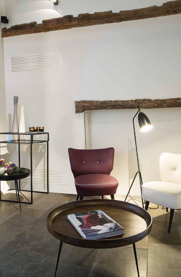
56 54
57 FNA-A + RXM-M9 Split Concealed floor standing unit Designed to be concealed in walls Combination with split outdoor units is ideal for small retail, offices or residential applications Unified range for R-32 and R-410A simplifying stock Ideal for installation in offices, hotels and residential applications Blends unobtrusively with any interior design: only the suction and discharge grills are visible Its low height (620 mm) enables the unit to fit perfectly beneath a window Requires very little installation space as the depth is only 200mm High ESP allows flexible installation RXM35M9 FNQ-A BRC1H51W BRP069A81 Indoor units Efficiency data FNA + RXM 25A + 25M9 35A + 35M9 50A + 50M9 60A + 60M9 Cooling capacity Nom. kw 2,60 3,40 5,00 6,00 Heating capacity Nom. kw 3,20 4,00 5,80 7,00 Power input Cooling Nom. kw 0,68 1,10 1,48 2,22 Heating Nom. kw 0,80 1,15 1,74 2,25 Seasonal efficiency (according to EN14825) Cooling Energy efficiency class A+ A Pdesign kw 2,60 3,40 5,00 6,00 SEER 5,68 5,70 5,77 5,56 Annual energy consumption kwh Heating (Average climate) Energy efficiency class A+ Pdesign kw 2,80 2,90 4,00 4,60 SCOP/A 4,24 4,05 4,09 4,16 Annual energy consumption kwh Nominal efficiency EER COP Annual energy consumption kwh Energy labeling Directive Cooling/Heating Indoor unit FNA 25A 35A 50A 60A Dimensions Unit HeightxWidthxDepth mm 620 / 720(2)x750x / 720(2)x1,150x200 Weight Unit kg Air filter Type Resin net Fan - Air flow rate Cooling High/Low m³/min 8.7/ /13.5 Heating High/Low m³/min 8.7/ /13.5 Fan - External static pressure High/Nom./Maximum available/high Pa 48/30/- 49/40/- Sound power level Cooling dba Sound pressure level Cooling High/Low dba 33/28 36/30 Heating High/Low dba 33/28 36/30 Refrigerant Type R-32 / R-410A Control systems Infrared remote control BRC4C65 Wired remote control BRC1H51 / BRC1E53A / BRC1E53B / BRC1E53C / BRC1D52 Power supply Phase / Frequency / Voltage Hz / V 1~ / 50/60 / /220 Outdoor unit RXM 25M9 35M9 50M9 60M9 Dimensions Unit HeightxWidthxDepth mm 550x765x x825x300 Weight Unit kg Sound power level Cooling dba Heating dba Sound pressure level Cooling Low/High dba 46/- 49/- 48/44 Heating Low/High dba 47/- 49/- 49/45 Operation range Cooling Ambient Min.~Max. CDB -10~46 Heating Ambient Min.~Max. CWB -15~18 Refrigerant Type R-32 GWP Charge kg/tco2eq 0.76/ / /0.98 Piping connections Liquid OD mm 6,35 6,4 Gas OD mm Piping length OU - IU Max. m System Chargeless m Additional refrigerant charge kg/m 0.02 (for piping length exceeding 10m) Level difference IU - OU Max. m 20.0 Power supply Phase/Frequency/Voltage Hz/V 1~/50/ Current - 50Hz Maximum fuse amps (MFA) A (1) EER/COP according to Eurovent 2012, for use outside EU only (2) Including installation legs (3) MFA is used to select the circuit breaker and the ground fault circuit interrupter (earth leakage circuit breaker). For more detailed information on each combination, please refer to the electrical data drawing. 55

58 56 Sky Air, from high specification, tailored solutions to primary cooling and heating
59 Combinations with R-410A outdoor units Indoor units Ceiling mounted cassettes 58 FCAHG-G 58 FCAG-A 60 FFA-A 64 Concealed ceiling units 65 FDXM-F3 66 FBA-A 67 FDA-A 70 FDQ-B 71 ADEQ-C 72 ABQ-C 73 Wall mounted units 75 FAA-A 75 Ceiling suspended units 77 FHA-A 77 FUA-A 82 Floor standing units 84 FVA-A 84 Concealed floor standing units 87 FNA-A 87 57
60 FCAHG-G + RZQG-L9V1/L(8)Y1 High COP, round flow cassette 360 air discharge for optimum efficiency and comfort Combination with Seasonal Smart ensures best in class quality, highest efficiency and performance High COP cassette ensures top performance, great savings in energy consumption and a comfortable environment for commercial applications Unified indoor unit range for R-32 and R-410A Automatic filter cleaning results in higher efficiency & comfort and lower maintenance costs. 2 filters available: standard filter and finer mesh filter (for fine dust applications e.g. clothing shops) Two optional intelligent sensors improve energy efficiency and comfort. Individual flap control: flexibility to suit every room layout without changing the location of the unit! Modern style decoration panel is available in 3 different variations: white (RAL9010) with grey louvers, full white (RAL9010) or auto cleaning panel 5 different fan speeds available for maximum comfort Reduced energy consumption thanks to specially developed small tube heat exchanger, DC fan motor and drain pump Optional fresh air intake RZQG L9V1_L(8)Y1 FCAHG-G BRC1H51W BRP069A81 Branch duct discharge allows to optimize air distribution in irregular shaped rooms or to supply air to small adjacent rooms Standard drain pump with 675mm lift increases flexibility and installation speed Efficiency data FCAHG + RZQG 71G + 100G + 125G + 140G + 71G + 100G + 125G + 140G + 71L9V1 100L9V1 125L9V1 140L9V1 71L8Y1 100L8Y1 125L8Y1 140LY1 Cooling capacity Nom. kw Heating capacity Nom. kw Power input Cooling Nom. kw Heating Nom. kw Seasonal efficiency (according to EN14825) 58 Cooling Energy efficiency class A++ - A++ - Pdesign kw SEER Annual energy consumption kwh Heating (Average climate) Energy efficiency class A+ A++ - A+ A++ - Pdesign kw SCOP/A Annual energy consumption kwh 2,344 3,296 3,829-2,344 3,296 3,829 - Nominal efficiency EER COP Annual energy consumption kwh 830 1,075 1, ,075 1,500 - Energy labeling Directive Cooling/Heating A/A -/- A/A -/- Indoor unit FCAHG 71G 100G 125G 140G 71G 100G 125G 140G Dimensions Unit HeightxWidthxDepth mm 288x840x840 Weight Unit kg 25 Air filter Type Resin net Decoration panel Model BYCQ140DGF9 - auto cleaning panel with fine mesh filter / BYCQ140DG9 - auto cleaning panel / BYCQ140DW - full white / BYCQ140D - white with grey louvers Colour Pure White (RAL 9010) Dimensions HeightxWidthxDepth mm 130x950x950 / 130x950x950 / 50x950x950 / 50x950x950 Weight kg 10.3 / 10.3 / 5.4 / 5.4 Fan Air flow rate Cooling Low/Medium/High m³/min 12.2/16.7/ /25.7/ /26.7/ /27.3/ /16.7/ /25.7/ /26.7/ /27.3/33.5 Heating Low/Medium/High m³/min 12.2/16.7/ /25.7/ /26.7/ /27.3/ /16.7/ /25.7/ /26.7/ /27.3/33.5 Sound power level Cooling dba Heating dba Sound pressure level Cooling Low/High dba 29/36 33/44 35/45 37/45 29/36 33/44 35/45 37/45 Heating Low/High dba 29/36 33/44 35/45 37/45 29/36 33/44 35/45 37/45 Control systems Infrared remote control BRC7FA532F Wired remote control BRC1H51 / BRC1E53A / BRC1E53B / BRC1E53C / BRC1D52 Power supply Phase/Frequency/Voltage Hz/V 1~/50/60/ /220 Outdoor unit RZQG 71L9V1 100L9V1 125L9V1 140L9V1 71L8Y1 100L8Y1 125L8Y1 140LY1 Dimensions Unit HeightxWidthxDepth mm 990x940x320 1,430x940x x940x320 1,430x940x320 Weight Unit kg Sound power level Cooling dba Sound pressure level Cooling Nom. dba Heating Nom. dba Operation range Cooling Ambient Min.~Max. CDB -15~50 Heating Ambient Min.~Max. CWB -20~15.5 Refrigerant Type/GWP R-410A/2,087.5 Charge kg/tco2eq 2.9/ / / /8.4 Piping connections Liquid/Gas mm 9.52/15.9 Piping length OU - IU Max. m System Equivalent m Chargeless m 30 Additional refrigerant charge kg/m See installation manual Level difference IU - OU Max. m 30.0 Power supply Phase/Frequency/Voltage Hz/V 1~/50/ N~/50/ Current - 50Hz Maximum fuse amps (MFA) A The BYCQ140D7W1W has white insulations. Be informed that formation of dirt on white insulation is visibly stronger and that it is consequently not advised to install the BYCQ140D7W1W decoration panel in environments exposed to concentrations of dirt. BYCQ140D7W1: pure white standard panel with grey louvers; BYCQ140D7W1W: pure white standard panel with white louvers; BYCQ140D7GW1: pure white auto cleaning panel. MFA is used to select the circuit breaker and the ground fault circuit interrupter (earth leakage circuit breaker). For more detailed information on each combination, please refer to the electrical data drawing.

61 FCAHG-G + RZQSG-L3/9V1/L(8)Y1 High COP, round flow cassette 360 air discharge for optimum efficiency and comfort Combination with Seasonal Classic ensures good value for money for all types of commercial applications High COP cassette ensures top performance, great savings in energy consumption and a comfortable environment for commercial applications Unified indoor unit range for R-32 and R-410A Automatic filter cleaning results in higher efficiency & comfort and lower maintenance costs. 2 filters available: standard filter and finer mesh filter (for fine dust applications e.g. clothing shops) Two optional intelligent sensors improve energy efficiency and comfort. Individual flap control: flexibility to suit every room layout without changing the location of the unit! Modern style decoration panel is available in 3 different variations: white (RAL9010) with grey louvers, full white (RAL9010) or auto cleaning panel RZQSG L9V1/L(8)Y1 FCAHG-G BRC1H51W BRP069A81 Indoor units Efficiency data FCAHG + RZQSG 71G + 71L3V1 100G + 125G + 140G + 100G + 125G + 100L9V1 125L9V1 140L9V1 100L8Y1 125L8Y1 140G + 140LY1 Cooling capacity Nom. kw Heating capacity Nom. kw Power input Cooling Nom. kw Heating Nom. kw Seasonal efficiency Cooling Energy efficiency class A++ A - A++ A - (according to Pdesign kw EN14825) SEER Annual energy consumption kwh Heating (Average climate) Energy efficiency class A+ - A+ - Pdesign kw SCOP/A Annual energy consumption kwh 2,563 2,615 2,742-2,615 2,742 - Nominal efficiency EER COP Annual energy consumption kwh 970 1,285 1,855-1,285 1,855 - Energy labeling Directive Cooling/Heating A/A -/- A/A -/- Indoor unit FCAHG 71G 100G 125G 140G 100G 125G 140G Dimensions Unit HeightxWidthxDepth mm 288x840x840 Weight Unit kg 25 Air filter Type Resin net Decoration panel Model BYCQ140DGF9 - auto cleaning panel with fine mesh filter / BYCQ140DG9 - auto cleaning panel / BYCQ140DW - full white / BYCQ140D - white with grey louvers Colour Pure White (RAL 9010) Dimensions HeightxWidthxDepth mm 130x950x950 / 130x950x950 / 50x950x950 / 50x950x950 Weight kg 10.3 / 10.3 / 5.4 / 5.4 Fan Air flow rate Cooling Low/Medium/High m³/min 12.2/16.7/ /25.7/ /26.7/ /27.3/ /25.7/ /26.7/ /27.3/33.5 Heating Low/Medium/High m³/min 12.2/16.7/ /25.7/ /26.7/ /27.3/ /25.7/ /26.7/ /27.3/33.5 Sound power level Cooling dba Heating dba Sound pressure level Cooling Low/High dba 29/36 33/44 35/45 37/45 33/44 35/45 37/45 Heating Low/High dba 29/36 33/44 35/45 37/45 33/44 35/45 37/45 Control systems Infrared remote control BRC7FA532F Wired remote control BRC1H51 / BRC1E53A / BRC1E53B / BRC1E53C / BRC1D52 Power supply Phase/Frequency/Voltage Hz/V 1~/50/60/ /220 Outdoor unit RZQSG 71L3V1 100L9V1 125L9V1 140L9V1 100L8Y1 125L8Y1 140LY1 Dimensions Unit HeightxWidthxDepth mm 770x900x x940x320 1,430x940x x940x320 1,430x940x320 Weight Unit kg Sound power level Cooling dba Sound pressure level Cooling Nom./Silent operation dba 49/47 53/- 54/- 53/- 54/- 53/- Heating Nom. dba Operation range Cooling Ambient Min.~Max. CDB -15.0~46-15~46 Heating Ambient Min.~Max. CWB -15~15.5 Refrigerant Type/GWP R-410A/2,087.5 Charge kg/tco2eq 2.75/ / / / /8.4 Piping connections Liquid/Gas mm 9.52/15.9 Piping length OU - IU Max. m 50 System Equivalent m 70 Chargeless m 30 Additional refrigerant charge kg/m See installation manual Level difference IU - OU Max. m Power supply Phase/Frequency/Voltage Hz/V 1~/50/ N~/50/ Current - 50Hz Maximum fuse amps (MFA) A The BYCQ140D7W1W has white insulations. Be informed that formation of dirt on white insulation is visibly stronger and that it is consequently not advised to install the BYCQ140D7W1W decoration panel in environments exposed to concentrations of dirt. BYCQ140D7W1: pure white standard panel with grey louvers; BYCQ140D7W1W: pure white standard panel with white louvers; BYCQ140D7GW1: pure white auto cleaning panel. MFA is used to select the circuit breaker and the ground fault circuit interrupter (earth leakage circuit breaker). For more detailed information on each combination, please refer to the electrical data drawing. 59
62 FCAG-A + RZQG-L9V1/L(8)Y1 Round flow cassette 360 air discharge for optimum efficiency and comfort Combination with Seasonal Smart ensures best in class quality, highest efficiency and performance Unified indoor unit range for R-32 and R-410A Automatic filter cleaning results in higher efficiency & comfort and lower maintenance costs. 2 filters available: standard filter and finer mesh filter (for fine dust applications e.g. clothing shops) Two optional intelligent sensors improve energy efficiency and comfort. Individual flap control: flexibility to suit every room layout without changing the location of the unit! Lowest installation height in the market: 214mm for class Modern style decoration panel is available in 3 different variations: white (RAL9010) with grey louvers, full white (RAL9010) or auto cleaning panel 5 different fan speeds available for maximum comfort Reduced energy consumption thanks to specially developed small tube heat exchanger, DC fan motor and drain pump Optional fresh air intake Branch duct discharge allows to optimize air distribution in irregular shaped rooms or to supply air to small adjacent rooms RZQG L9V1/L(8)Y1 FCAG-A BRC1H51W BRP069A81 Standard drain pump with 675mm lift increases flexibility and installation speed Efficiency data FCAG + RZQG 71A + 100A + 125A + 140A + 71A + 100A + 125A + 140A + 71L9V1 100L9V1 125L9V1 140L9V1 71L8Y1 100L8Y1 125L8Y1 140LY1 Cooling capacity Nom. kw Heating capacity Nom. kw Power input Cooling Nom. kw Heating Nom. kw Seasonal efficiency (according to EN14825) 60 Cooling Energy efficiency class A++ A+ - A++ A+ - Pdesign kw SEER Annual energy consumption kwh Heating (Average climate) Energy efficiency class A+ A++ A+ - A+ A++ A+ - Pdesign kw SCOP/A Annual energy consumption kwh 2,110 3,432 4,323-2,110 3,432 4,323 - Nominal efficiency EER COP Annual energy consumption kwh 1,005 1,225 1,610-1,005 1,225 1,610 - Energy labeling Directive Cooling/Heating A/A -/- A/A -/- Indoor unit FCAG 71A 100A 125A 140A 71A 100A 125A 140A Dimensions Unit HeightxWidthxDepth mm 204x840x x840x x840x x840x840 Weight Unit kg Air filter Type Resin net Decoration panel Model BYCQ140DGF9 - auto cleaning panel with fine mesh filter / BYCQ140DG9 - auto cleaning panel / BYCQ140DW - full white / BYCQ140D - white with grey louvers Colour Pure White (RAL 9010) Dimensions HeightxWidthxDepth mm 130x950x950 / 130x950x950 / 50x950x950 / 50x950x950 Weight kg 10.3 / 10.3 / 5.4 / 5.4 Fan Air flow rate Cooling Low/Medium/High m³/min 9.3/12.5/ /17.6/ /19.2/ /12.5/ /17.6/ /19.2/26.0 Heating Low/Medium/High m³/min 9.1/12.1/ /17.6/ /19.2/ /12.1/ /17.6)/ /19.2/26.0 Sound power level Cooling dba Heating dba Sound pressure level Cooling Low/High dba 28/35 29/37 29/41 28/35 29/37 29/41 Heating Low/High dba 28/33 29/37 29/41 28/33 29/37 29/41 Control systems Infrared remote control BRC7FA532F Wired remote control BRC1H51 / BRC1E53A / BRC1E53B / BRC1E53C / BRC1D52 Power supply Phase/Frequency/Voltage Hz/V 1~/50/60/ /220 Outdoor unit RZQG 71L9V1 100L9V1 125L9V1 140L9V1 71L8Y1 100L8Y1 125L8Y1 140LY1 Dimensions Unit HeightxWidthxDepth mm 990x940x320 1,430x940x x940x320 1,430x940x320 Weight Unit kg Sound power level Cooling dba Sound pressure level Cooling Nom. dba Heating Nom. dba Operation range Cooling Ambient Min.~Max. CDB -15~50 Heating Ambient Min.~Max. CWB -20~15.5 Refrigerant Type/GWP R-410A/2,087.5 Charge kg/tco2eq 2.9/ / / /8.4 Piping connections Liquid/Gas mm 9.52/15.9 Piping length OU - IU Max. m System Equivalent m Chargeless m 30 Additional refrigerant charge kg/m See installation manual Level difference IU - OU Max. m 30.0 Power supply Phase/Frequency/Voltage Hz/V 1~/50/ N~/50/ Current - 50Hz Maximum fuse amps (MFA) A The BYCQ140D7W1W has white insulations. Be informed that formation of dirt on white insulation is visibly stronger and that it is consequently not advised to install the BYCQ140D7W1W decoration panel in environments exposed to concentrations of dirt. BYCQ140D7W1: pure white standard panel with grey louvers; BYCQ140D7W1W: pure white standard panel with white louvers; BYCQ140D7GW1: pure white auto cleaning panel. MFA is used to select the circuit breaker and the ground fault circuit interrupter (earth leakage circuit breaker). For more detailed information on each combination, please refer to the electrical data drawing.
63 FCAG-A + RZQSG-L3/9V1/L(8)Y1 Round flow cassette 360 air discharge for optimum efficiency and comfort Combination with Seasonal Classic ensures good value for money for all types of commercial applications Unified indoor unit range for R-32 and R-410A Automatic filter cleaning results in higher efficiency & comfort and lower maintenance costs. 2 filters available: standard filter and finer mesh filter (for fine dust applications e.g. clothing shops) Two optional intelligent sensors improve energy efficiency and comfort. Individual flap control: flexibility to suit every room layout without changing the location of the unit! Lowest installation height in the market: 214mm for class Modern style decoration panel is available in 3 different variations: white (RAL9010) with grey louvers, full white (RAL9010) or auto cleaning panel RZQSG l9V1/L(8)Y1 FCAG-A BRC1H51W BRP069A81 Indoor units Efficiency data FCAG + RZQSG 71A + 71L3V1 100A + 125A + 140A + 100A + 125A + 100L9V1 125L9V1 140L9V1 100L8Y1 125L8Y1 140A + 140LY1 Cooling capacity Nom. kw Heating capacity Nom. kw Power input Cooling Nom. kw Heating Nom. kw Seasonal efficiency Cooling Energy efficiency class A++ A - A++ A - (according to Pdesign kw EN14825) SEER Annual energy consumption kwh Heating (Average climate) Energy efficiency class A+ - A+ - Pdesign kw SCOP/A Annual energy consumption kwh 2,162 2,596 2,804-2,596 2,804 - Nominal efficiency EER COP Annual energy consumption kwh 1,060 1,440 1,870-1,440 1,870 2,225 Energy labeling Directive Cooling/Heating A/A A/B -/- A/A A/B -/- Indoor unit FCAG 71A 100A 125A 140A 100A 125A 140A Dimensions Unit HeightxWidthxDepth mm 204x840x x840x x840x840 Weight Unit kg Air filter Type Resin net Decoration panel Model BYCQ140DGF9 - auto cleaning panel with fine mesh filter / BYCQ140DG9 - auto cleaning panel / BYCQ140DW - full white / BYCQ140D - white with grey louvers Colour Pure White (RAL 9010) Dimensions HeightxWidthxDepth mm 130x950x950 / 130x950x950 / 50x950x950 / 50x950x950 Weight kg 10.3 / 10.3 / 5.4 / 5.4 Fan Air flow rate Cooling Low/Medium/High m³/min 9.3/12.5/ /17.6/ /19.2/ /17.6/ /19.2/26.0 Heating Low/Medium/High m³/min 9.1/12.1/ /17.6/ /19.2/ /17.6)/ /19.2/26.0 Sound power level Cooling dba Heating dba Sound pressure level Cooling Low/High dba 28/35 29/37 29/41 29/37 29/41 Heating Low/High dba 28/33 29/37 29/41 29/37 29/41 Control systems Infrared remote control BRC7FA532F Wired remote control BRC1H51 / BRC1E53A / BRC1E53B / BRC1E53C / BRC1D52 Power supply Phase/Frequency/Voltage Hz/V 1~/50/60/ /220 Outdoor unit RZQSG 71L3V1 100L9V1 125L9V1 140L9V1 100L8Y1 125L8Y1 140LY1 Dimensions Unit HeightxWidthxDepth mm 770x900x x940x320 1,430x940x x940x320 1,430x940x320 Weight Unit kg Sound power level Cooling dba Sound pressure level Cooling Nom./Silent operation dba 49/47 53/- 54/- 53/- 54/- 53/- Heating Nom. dba Operation range Cooling Ambient Min.~Max. CDB -15.0~46-15~46 Heating Ambient Min.~Max. CWB -15~15.5 Refrigerant Type/GWP R-410A/2,087.5 Charge kg/tco2eq 2.75/ / / / /8.4 Piping connections Liquid/Gas mm 9.52/15.9 Piping length OU - IU Max. m 50 System Equivalent m 70 Chargeless m 30 Additional refrigerant charge kg/m See installation manual Level difference IU - OU Max. m Power supply Phase/Frequency/Voltage Hz/V 1~/50/ N~/50/ Current - 50Hz Maximum fuse amps (MFA) A The BYCQ140D7W1W has white insulations. Be informed that formation of dirt on white insulation is visibly stronger and that it is consequently not advised to install the BYCQ140D7W1W decoration panel in environments exposed to concentrations of dirt. BYCQ140D7W1: pure white standard panel with grey louvers; BYCQ140D7W1W: pure white standard panel with white louvers; BYCQ140D7GW1: pure white auto cleaning panel. MFA is used to select the circuit breaker and the ground fault circuit interrupter (earth leakage circuit breaker). For more detailed information on each combination, please refer to the electrical data drawing. 61
64 FCAG-A + AZQS-B(8)V1/BY1 Round flow cassette 360 air discharge for optimum efficiency and comfort Unified indoor unit range for R-32 and R-410A Automatic filter cleaning results in higher efficiency & comfort and lower maintenance costs. 2 filters available: standard filter and finer mesh filter (for fine dust applications e.g. clothing shops) Two optional intelligent sensors improve energy efficiency and comfort. Individual flap control: flexibility to suit every room layout without changing the location of the unit! Lowest installation height in the market: 214mm for class Modern style decoration panel is available in 3 different variations: white (RAL9010) with grey louvers, full white (RAL9010) or auto cleaning panel FCAG-A AZQS140B8V1/BY1 BRC1H51W BRP069A81 Efficiency data FCAG + AZQS 71A + 100A + 125A + 140A + 71BV1 100B8V1 125B8V1 140B8V1 100A + 100BY1 125A + 125BY1 140A + 140BY1 Cooling capacity Nom. kw Heating capacity Nom. kw Power input Cooling Nom. kw Heating Nom. kw Seasonal efficiency Cooling Energy efficiency class A+ A - A - (according to Pdesign kw EN14825) SEER Annual energy consumption kwh Heating (Average climate) Energy efficiency class A+ A - A - Pdesign kw SCOP/A Annual energy consumption kwh 2,216 2,762-2,764 - Nominal efficiency EER COP Annual energy consumption kwh 1,093 1,480 1,952 2,313 1,480 1,952 2,313 Energy labeling Directive Cooling/Heating B / A A/B B/B C/C A/B B/B -/- Indoor unit FCAG 71A 100A 125A 140A 100A 125A 140A Dimensions Unit HeightxWidthxDepth mm 204x840x x840x840 Weight Unit kg Air filter Type Resin net Decoration panel Model BYCQ140DGF9 - auto cleaning panel with fine mesh filter / BYCQ140DG9 - auto cleaning panel / BYCQ140DW - full white / BYCQ140D - white with grey louvers Colour Pure White (RAL 9010) Dimensions HeightxWidthxDepth mm 130x950x950 / 130x950x950 / 50x950x950 / 50x950x950 Weight kg 10.3 / 10.3 / 5.4 / 5.4 Fan Air flow rate Cooling Low/Medium/High m³/min 9.3/12.5/ /17.6/ /19.2/ /17.6/ /19.2/26.0 Heating Low/Medium/High m³/min 9.1/12.1/ /17.6/ /19.2/ /17.6/ /19.2/26.0 Sound power level Cooling dba Heating dba Sound pressure level Cooling Low/High dba 28/35 29/37 29/41 29/37 29/41 Heating Low/High dba 28/33 29/37 29/41 29/37 29/41 Control systems Infrared remote control BRC7FA532F Wired remote control BRC1H51 / BRC1E53A / BRC1E53B / BRC1E53C / BRC1D52 Power supply Phase/Frequency/Voltage Hz/V 1~/50/60/ /220 Outdoor unit AZQS/AZQS 71BV1 100B8V1 125B8V1 140B8V1 100BY1 125BY1 140BY1 Dimensions Unit HeightxWidthxDepth mm 770x900x x940x320 1,430x940x x940x320 1,430x940x320 Weight Unit kg Sound power level Cooling dba Sound pressure level Cooling Nom. dba Heating Nom. dba Night quiet mode Level 1 dba Operation range Cooling Ambient Min.~Max. CDB -5~46 Heating Ambient Min.~Max. CWB -15~15.5 Refrigerant Type/GWP R-410A/2,087.5 Charge kg/tco2eq 2.75/ / / / /8.4 Piping connections Liquid/Gas mm 9.52/15.9 Piping length OU - IU Max. m 50 System Equivalent m 70 Chargeless m 30 Additional refrigerant charge kg/m See installation manual Level difference IU - OU Max. m 30.0 Power supply Phase/Frequency/Voltage Hz/V 1~/50/ N~/50/ Current - 50Hz Maximum fuse amps (MFA) A EER/COP according to Eurovent 2012, for use outside EU only The BYCQ140D7W1W has white insulations. Be informed that formation of dirt on white insulation is visibly stronger and that it is consequently not advised to install the BYCQ140D7W1W decoration panel in environments exposed to concentrations of dirt. BYCQ140D7W1: pure white standard panel with grey louvers; BYCQ140D7W1W: pure white standard panel with white louvers; BYCQ140D7GW1: pure white auto cleaning panel.

65 FCAG-A + RXS-L(3) Split Round flow cassette 360 air discharge for optimum efficiency and comfort Combination with split outdoor units is ideal for small retail, offices or residential applications Unified indoor unit range for R-32 and R-410A Automatic filter cleaning results in higher efficiency & comfort and lower maintenance costs. 2 filters available: standard filter and finer mesh filter (for fine dust applications e.g. clothing shops) Two optional intelligent sensors improve energy efficiency and comfort. Individual flap control: flexibility to suit every room layout without changing the location of the unit! Lowest installation height in the market: 214mm for class Modern style decoration panel is available in 3 different variations: white (RAL9010) with grey louvers, full white (RAL9010) or auto cleaning panel RXS35L3 FCAG-A BRC1H51W BRP069A81 Indoor units Efficiency data FCAG + RXS 35A + 35L3 50A + 50L 60A + 60L Cooling capacity Nom. kw Heating capacity Nom. kw Power input Cooling Nom. kw Heating Nom. kw Seasonal efficiency (according to EN14825) Cooling Energy efficiency class A++ Pdesign kw SEER Annual energy consumption kwh Heating (Average climate) Energy efficiency class A++ A+ Pdesign kw SCOP/A Annual energy consumption kwh 949 1,426 1,646 Nominal efficiency EER COP Annual energy consumption kwh Energy labeling Directive Cooling/Heating A/B A/A A/B Indoor unit FCAG 35A 50A 60A Dimensions Unit HeightxWidthxDepth mm 204x840x840 Weight Unit kg Air filter Type Resin net Decoration panel Model BYCQ140DGF9 - auto cleaning panel with fine mesh filter / BYCQ140DG9 - auto cleaning panel / BYCQ140DW - full white / BYCQ140D - white with grey louvers Colour Pure White (RAL 9010) Dimensions HeightxWidthxDepth mm 130x950x950 / 130x950x950 / 50x950x950 / 50x950x950 Weight kg 10.3 / 10.3 / 5.4 / 5.4 Fan Air flow rate Cooling Low/Medium/High m³/min 8.7/10.6/ /10.7/ /11.2/13.6 Heating Low/Medium/High m³/min 9.3/11.6/ /10.7/ /11.2/13.6 Sound power level Cooling dba Heating dba Sound pressure level Cooling Low/High dba 27/31 28/33 Heating Low/High dba 27/31 28/33 Control systems Infrared remote control BRC7FA532F Wired remote control BRC1H51 / BRC1E53A / BRC1E53B / BRC1E53C / BRC1D52 Power supply Phase/Frequency/Voltage Hz/V 1~/50/60/ /220 Outdoor unit RXS 35L3 50L 60L Dimensions Unit HeightxWidthxDepth mm 550x765x x825x300 Weight Unit kg Sound power level Cooling dba Heating dba Sound pressure level Cooling Low/High dba -/48 44/48 46/49 Heating Low/High dba -/48 45/48 46/49 Operation range Cooling Ambient Min.~Max. CDB -10~46 Heating Ambient Min.~Max. CWB -15~18 Refrigerant Type R-410A GWP 2,087.5 Charge kg/tco2eq 1.2/ / /3.1 Piping connections Liquid OD mm 6.35 Gas OD mm Piping OU - IU Max. m length System Chargeless m 10 - Additional refrigerant charge kg/m 0.02 (for piping length exceeding 10m) (for piping length exceeding 10m) Level difference IU - OU Max. m Power supply Phase/Frequency/Voltage Hz/V 1~/50/ ~/50/ Current - 50Hz Maximum fuse amps (MFA) A - EER/COP according to Eurovent 2012, for use outside EU only The BYCQ140D7W1W has white insulations. Be informed that formation of dirt on white insulation is visibly stronger and that it is consequently not advised to install the BYCQ140D7W1W decoration panel in environments exposed to concentrations of dirt. BYCQ140D7W1: pure white standard panel with grey louvers; BYCQ140D7W1W: pure white standard panel with white louvers; BYCQ140D7GW1: pure white auto cleaning panel. 63

66 FFA-A + RXS-L(3) Split Fully flat cassette Unique design in the market that integrates fully flat into the ceiling Combination with split outdoor units is ideal for small retail, offices or residential applications Fully flat integration in standard architectural ceiling tiles, leaving only 8mm Remarkable blend of iconic design and engineering excellence with an elegant finish in white or a combination of silver and white Unified indoor unit range for R-32 and R-410A Two optional intelligent sensors improve energy efficiency and comfort. Individual flap control: flexibility to suit every room layout without changing the location of the unit! Reduced energy consumption thanks to specially developed small tube heat exchanger, DC fan motor and drain pump Optional fresh air intake Branch duct discharge allows to optimize air distribution in irregular shaped rooms or to supply air to small adjacent rooms Standard drain pump with 630mm lift increases flexibility and installation speed RX35L3 FFA-A BRC1H51W BRP069A81 Efficiency data FFA + RXS 25A + 25L3 35A + 35L3 50A + 50L 60A + 60L Cooling capacity Nom. kw Heating capacity Nom. kw Power input Cooling Nom. kw Heating Nom. kw Seasonal efficiency (according to EN14825) Cooling Energy efficiency class A++ A+ Pdesign kw SEER Annual energy consumption kwh Heating (Average climate) Energy efficiency class A+ A A+ Pdesign kw SCOP/A Annual energy consumption kwh 763 1,059 1,378 1,373 Nominal efficiency EER COP Annual energy consumption kwh Energy labeling Directive Cooling/Heating A/A A/B B/B Indoor unit FFA 25A 35A 50A 60A Dimensions Unit HeightxWidthxDepth mm 260x575x575 Weight Unit kg Air filter Type Resin net Decoration panel Model BYFQ60C2W1W/BYFQ60C2W1S/BYFQ60B2W1/BYFQ60B3W1 Colour White (N9.5)/SILVER/White (RAL9010)/WHITE (RAL9010) Dimensions HeightxWidthxDepth mm 46x620x620 / 46x620x620 / 55x700x700 / 55x700x700 Weight kg 2.8/2.8/2.7/2.7 Fan Air flow rate Cooling Low/Medium/High m³/min 6.5/8.0 / /8.5 / /10.0 / /12.5 /14.5 Heating Low/Medium/High m³/min 6.5/8.0 / /8.5 / /10.0 / /12.5 /14.5 Sound power level Cooling dba Sound pressure level Cooling Low/High dba 25.0/ / / /43.0 Heating Low/High dba 25.0/ / / /43.0 Control systems Infrared remote control BRC7EB530W (standard panel) / BRC7F530W (white panel) / BRC7F530S (grey panel) Wired remote control BRC1H51 / BRC1E53A / BRC1E53B / BRC1E53C / BRC1D52 Power supply Phase/Frequency/Voltage Hz/V 1~/50/ Outdoor unit RXS 25L3 35L3 50L 60L Dimensions Unit HeightxWidthxDepth mm 550x765x x825x300 Weight Unit kg Sound power level Cooling dba Heating dba Sound pressure level Cooling Low/High dba -/46 -/48 44/48 46/49 Heating Low/High dba -/47 -/48 45/48 46/49 Operation range Cooling Ambient Min.~Max. CDB -10~46 Heating Ambient Min.~Max. CWB -15~18 Refrigerant Type R-410A GWP 2,087.5 Charge kg/tco2eq 1.0/ / / /3.1 Piping connections Liquid OD mm 6.35 Gas OD mm Piping OU - IU Max. m length System Chargeless m 10 - Additional refrigerant charge kg/m 0.02 (for piping length exceeding 10m) (for piping length exceeding 10m) Level difference IU - OU Max. m Power supply Phase/Frequency/Voltage Hz/V 1~/50/ ~/50/ Current - 50Hz Maximum fuse amps (MFA) A - 64
67 65 Indoor units

68 FDXM-F3 + RXS-L(3) Split Concealed ceiling unit rear suction Compact concealed ceiling unit, with a height of only 200mm Invisible unit as the unit is concealed in the ceiling: only the suction and discharge grilles are visible Compact dimensions, can easily be mounted in a ceiling void of only 240mm Medium external static pressure up to 40Pa facilitates unit use with flexible ducts of varying lengths Unified indoor unit range for R-32 and R-410A NEW Auto cleaning filter option ensures maximum efficiency, comfort and reliability by regular filter cleaning NEW Multi zoning kit allows multiple individually-controlled climate zones to be served by one indoor unit Online controller (optional): control your indoor from any location with an app, via your local network or internet and keep an overview on your energy consumption Low energy consumption thanks to DC fan motor outblow RXS25-35L3 FDXM-F3 BRC1H51W bottom suction BRP069A81 NEW with auto cleaning and multi zoning option Efficiency data FDXM + RXS 25F3 + 25L3 35F3 + 35L3 50F3 + 50L 60F3 + 60L Cooling capacity Nom. kw Heating capacity Nom. kw Power input Cooling Nom. kw Heating Nom. kw Seasonal efficiency (according to EN14825) 66 Cooling Energy efficiency class A+ A A+ A Pdesign kw SEER Annual energy consumption kwh Heating (Average climate) Energy efficiency class A+ A Pdesign kw SCOP/A Annual energy consumption kwh 858 1,047 1,425 1,693 Nominal efficiency EER COP Annual energy consumption kwh ,030 Energy labeling Directive Cooling/Heating A/A B/A B/D C/C Indoor unit FDXM 25F3 35F3 50F3 60F3 Dimensions Unit HeightxWidthxDepth mm 200x750x x1,150x620 Weight Unit kg Air filter Type Removable / washable Fan Air flow rate Cooling Low/Medium/High m³/min 7.3/8.0 / /14.6 / /14.8 /16.0 Heating Low/Medium/High m³/min 7.3/8.0 / /14.6 / /14.8 /16.0 External static pressure Nom. Pa Sound power level Cooling dba Heating dba Sound pressure level Cooling Low/High dba 27/35 30/38 Heating Low/High dba 27/35 30/38 Control systems Infrared remote control BRC4C65 Wired remote control BRC1H51 / BRC1E53A / BRC1E53B / BRC1E53C / BRC1D52 Power supply Phase/Frequency/Voltage Hz/V 1~/50/ Outdoor unit RXS 25L3 35L3 50L 60L Dimensions Unit HeightxWidthxDepth mm 550x765x x825x300 Weight Unit kg Sound power level Cooling dba Heating dba Sound pressure level Cooling Low/High dba -/46 -/48 44/48 46/49 Heating Low/High dba -/47 -/48 45/48 46/49 Operation range Cooling Ambient Min.~Max. CDB -10~46 Heating Ambient Min.~Max. CWB -15~18 Refrigerant Type R-410A GWP 2,087.5 Charge kg/tco2eq 1.0/ / / /3.1 Piping connections Liquid OD mm 6.35 Gas OD mm Piping length OU - IU Max. m System Chargeless m 10 - Additional refrigerant charge kg/m 0.02 (for piping length exceeding 10m) Level difference IU - OU Max. m Power supply Phase/Frequency/Voltage Hz/V 1~/50/ ~/50/ Current - 50Hz Maximum fuse amps (MFA) A - Nominal cooling capacities are based on: indoor temperature: 27 CDB, 19 CWB, outdoor temperature: 35 CDB, equivalent refrigerant piping: 5m, level difference: 0m. Nominal heating capacities are based on: indoor temperature: 20 CDB, outdoor temperature: 7 CDB, 6 CWB, equivalent refrigerant piping: 5m, level difference: 0m.
69 FBA-A + RZQG-L9V1/L(8)Y1 Concealed ceiling unit with medium ESP Slimmest yet most powerful medium static pressure unit on the market Combination with Seasonal Smart ensures best in class quality, highest efficiency and performance Slimmest unit in class, only 245mm (300mm built-in height) and therefore narrow ceiling voids are no longer a challenge Low operation sound level down to 25dBA Medium external static pressure up to 150Pa facilitates using flexible ducts of varying lengths Unified indoor unit range for R-32 and R-410A Possibility to change ESP via wired remote control allows optimisation of the supply air volume Discretely concealed in the ceiling: only the suction and discharge grilles are visible NEW Multi zoning kit allows multiple individually-controlled climate zones to be served by one indoor unit Reduced energy consumption thanks to specially developed DC fan motor Optional fresh air intake outblow RZQG L9V1/L(8)Y1 FBA-A BRC1H51W bottom suction BRP069A81 rear suction NEW with multi zoning option Flexible installation: air suction direction can be altered from rear to bottom suction and choice between free use or connection to optional suction grilles Standard built-in drain pump with 625mm lift increases flexibility and installation speed Indoor units Efficiency data FBA + RZQG 71A + 100A + 125A + 140A + 71A + 100A + 125A + 140A + 71L9V1 100L9V1 125L9V1 140L9V1 71L8Y1 100L8Y1 125L8Y1 140LY1 Cooling capacity Nom. kw Heating capacity Nom. kw Power input Cooling Nom. kw Heating Nom. kw Seasonal efficiency (according to EN14825) Cooling Energy efficiency class A++ A+ A++ - A++ A+ A++ - Pdesign kw SEER Annual energy consumption kwh Heating (Average climate) Energy efficiency class A+ A++ A+ - A+ A++ A+ - Pdesign kw SCOP/A Annual energy consumption kwh 1,949 3,310 4,154-1,949 3,310 4,154 - Nominal efficiency EER COP Annual energy consumption kwh 944 1,247 1, ,247 1,813 - Energy labeling Directive Cooling/Heating A/A -/- A/A -/- Indoor unit FBA 71A 100A 125A 140A 71A 100A 125A 140A Dimensions Unit HeightxWidthxDepth mm 245x1,000x x1,400x x1,000x x1,400x800 Weight Unit kg Air filter Type Resin net Fan Air flow rate Cooling Low/Medium/High m³/min 12.5/15.0 / /26.0 / /29.0 / /15.0 / /26.0 / /29.0 /34.0 Heating Low/Medium/High m³/min 12.5/15.0 / /26.0 / /29.0 / /15.0 / /26.0 / /29.0 /34.0 External static pressure Nom./High Pa 30/150 40/150 50/150 30/150 40/150 50/150 Sound power level Cooling dba Sound pressure level Cooling Low/High dba 25.0/ / / / / /37.0 Heating Low/High dba 25.0/ / / / / /38.0 Control systems Infrared remote control BRC4C65 / BRC4C66 Wired remote control BRC1H51 / BRC1E53A / BRC1E53B / BRC1E53C / BRC1D52 Power supply Phase/Frequency/Voltage Hz/V 1~/50/60/ /220 Outdoor unit RZQG 71L9V1 100L9V1 125L9V1 140L9V1 71L8Y1 100L8Y1 125L8Y1 140LY1 Dimensions Unit HeightxWidthxDepth mm 990x940x320 1,430x940x x940x320 1,430x940x320 Weight Unit kg Sound power level Cooling dba Sound pressure level Cooling Nom. dba Heating Nom. dba Operation range Cooling Ambient Min.~Max. CDB -15~50 Heating Ambient Min.~Max. CWB -20~15.5 Refrigerant Type/GWP R-410A/2,087.5 Charge kg/tco2eq 2.9/ / / /8.4 Piping connections Liquid/Gas mm 9.52/15.9 Piping length OU - IU Max. m System Equivalent m Chargeless m 30 Additional refrigerant charge kg/m See installation manual Level difference IU - OU Max. m 30.0 Power supply Phase/Frequency/Voltage Hz/V 1~/50/ N~/50/ Current - 50Hz Maximum fuse amps (MFA) A MFA is used to select the circuit breaker and the ground fault circuit interrupter (earth leakage circuit breaker). For more detailed information on each combination, please refer to the electrical data drawing. 67
70 FBA-A + RZQSG-L3/9V1/L(8)Y1 Concealed ceiling unit with medium ESP Slimmest yet most powerful medium static pressure unit on the market outblow NEW Combination with Seasonal Classic ensures good value for money for all types of commercial applications Slimmest unit in class, only 245mm (300mm built-in height) and therefore narrow ceiling voids are no longer a challenge Low operation sound level down to 25dBA Medium external static pressure up to 150Pa facilitates using flexible ducts of varying lengths Unified indoor unit range for R-32 and R-410A Possibility to change ESP via wired remote control allows optimisation of the supply air volume Discretely concealed in the ceiling: only the suction and discharge grilles are visible Multi zoning kit allows multiple individually-controlled climate zones to be served by one indoor unit RZQSG L9V1/L(8)Y1 FBA-A BRC1H51W bottom suction BRP069A81 rear suction NEW with multi zoning option Optimised supply air volume Automatically selects the most appropriate fan curve to achieve the units nominal air flow within ±10% Why? After installation the real ducting will frequently differ from the initially calculated air flow resistance the real air flow may be much lower or higher than nominal, leading to a lack of capacity or uncomfortable air temperature Automatic Airflow Adjustment function will adapt the unit s fan speed to any ducting automatically (10 or more fan curves are available on every model), making installation much faster External static pressure (Pa) Fan characteristic curves Duct resistance curves Air flow (rated) Air flow (actual) Air flow (with automatic adjustment) ±10% Air flow (m 3 /min) Efficiency data FBA + RZQSG 71A + 71L3V1 100A + 125A + 140A + 100A + 125A + 100L9V1 125L9V1 140L9V1 100L8Y1 125L8Y1 140A + 140LY1 Cooling capacity Nom. kw Heating capacity Nom. kw Power input Cooling Nom. kw Heating Nom. kw Seasonal efficiency Cooling Energy efficiency class A+ A - A+ A - (according to Pdesign kw EN14825) SEER Heating (Average climate) Annual energy consumption kwh Energy efficiency class A+ - A+ - Pdesign kw SCOP/A Annual energy consumption kwh 2,095 2,564 2,653-2,564 2,653 - Nominal efficiency EER COP Annual energy consumption kwh 991 1,418 1,858-1,418 1,858 - Energy labeling Directive Cooling/Heating A/A -/- A/A -/- Indoor unit FBA 71A 100A 125A 140A 100A 125A 140A Dimensions Unit HeightxWidthxDepth mm 245x1,000x x1,400x800 Weight Unit kg Air filter Type Resin net Fan Air flow rate Cooling Low/Medium/High m³/min 12.5/15.0 / /26.0 / /29.0 / /26.0 / /29.0 /34.0 Heating Low/Medium/High m³/min 12.5/15.0 / /26.0 / /29.0 / /26.0 / /29.0 /34.0 External static pressure Nom./High Pa 30/150 40/150 50/150 40/150 50/150 Sound power level Cooling dba Sound pressure level Cooling Low/High dba 25.0/ / / / /37.0 Heating Low/High dba 25.0/ / / / /38.0 Control systems Infrared remote control BRC4C65 / BRC4C66 Wired remote control BRC1H51 / BRC1E53A / BRC1E53B / BRC1E53C / BRC1D52 Power supply Phase/Frequency/Voltage Hz/V 1~/50/60/ /220 Outdoor unit RZQSG 71L3V1 100L9V1 125L9V1 140L9V1 100L8Y1 125L8Y1 140LY1 Dimensions Unit HeightxWidthxDepth mm 770x900x x940x320 1,430x940x x940x320 1,430x940x320 Weight Unit kg Sound power level Cooling dba Sound pressure level Cooling Nom./Silent operation dba 49/47 53/- 54/- 53/- 54/- 53/- Heating Nom. dba Operation range Cooling Ambient Min.~Max. CDB -15.0~46-15~46 Heating Ambient Min.~Max. CWB -15~15.5 Refrigerant Type/GWP R-410A/2,087.5 Charge kg/tco2eq 2.75/ / / / /8.4 Piping connections Liquid/Gas mm 9.52/15.9 Piping length OU - IU Max. m 50 System Equivalent m 70 Chargeless m 30 Additional refrigerant charge kg/m See installation manual Level difference IU - OU Max. m Power supply Phase/Frequency/Voltage Hz/V 1~/50/ N~/50/ Current - 50Hz Maximum fuse amps (MFA) A MFA is used to select the circuit breaker and the ground fault circuit interrupter (earth leakage circuit breaker). For more detailed information on each combination, please refer to the electrical data drawing.
71 FBA-A + RXS-L(3) Split Concealed ceiling unit with medium ESP NEW Slimmest yet most powerful medium static pressure unit on the market Combination with split outdoor units is ideal for small retail, offices or residential applications Slimmest unit in class, only 245mm (300mm built-in height) and therefore narrow ceiling voids are no longer a challenge Low operation sound level down to 25dBA Medium external static pressure up to 150Pa facilitates using flexible ducts of varying lengths Unified indoor unit range for R-32 and R-410A Possibility to change ESP via wired remote control allows optimisation of the supply air volume Discretely concealed in the ceiling: only the suction and discharge grilles are visible Multi zoning kit allows multiple individually-controlled climate zones to be served by one indoor unit RXS35L3 outblow FBA-A BRC1H51W bottom suction BRP069A81 rear suction NEW with multi zoning option Indoor units Efficiency data FBA + RXS 35A + 35L3 50A + 50L 60A + 60L Cooling capacity Nom. kw Heating capacity Nom. kw Power input Cooling Nom. kw Heating Nom. kw Seasonal efficiency (according to EN14825) Cooling Energy efficiency class A++ A+ Pdesign kw SEER Annual energy consumption kwh Heating (Average climate) Energy efficiency class A+ Pdesign kw SCOP/A Annual energy consumption kwh 998 1,517 1,606 Nominal efficiency EER COP Annual energy consumption kwh Energy labeling Directive Cooling/Heating A/A Indoor unit FBA 35A 50A 60A Dimensions Unit HeightxWidthxDepth mm 245x700x x1,000x800 Weight Unit kg Air filter Type Resin net Fan Air flow rate Cooling Low/Medium/High m³/min 10.5/12.5 / /15.0 /18.0 Heating Low/Medium/High m³/min 10.5/12.5 / /15.0 /18.0 External static pressure Nom./High Pa 30/150 Sound power level Cooling dba Sound pressure level Cooling Low/High dba 29.0/ /30.0 Heating Low/High dba 29.0/ /31.0 Control systems Infrared remote control BRC4C65 / BRC4C66 Wired remote control BRC1H51 / BRC1E53A / BRC1E53B / BRC1E53C / BRC1D52 Power supply Phase/Frequency/Voltage Hz/V 1~/50/60/ /220 Outdoor unit RXS 35L3 50L 60L Dimensions Unit HeightxWidthxDepth mm 550x765x x825x300 Weight Unit kg Sound power level Cooling dba Heating dba Sound pressure level Cooling Low/High dba -/48 44/48 46/49 Heating Low/High dba -/48 45/48 46/49 Operation range Cooling Ambient Min.~Max. CDB -10~46 Heating Ambient Min.~Max. CWB -15~18 Refrigerant Type R-410A GWP 2,087.5 Charge kg/tco2eq 1.2/ / /3.1 Piping connections Liquid OD mm 6.35 Gas OD mm Piping length OU - IU Max. m System Chargeless m 10 - Additional refrigerant charge kg/m 0.02 (for piping length exceeding 10m) (for piping length exceeding 10m) Level difference IU - OU Max. m Power supply Phase/Frequency/Voltage Hz/V 1~/50/ ~/50/ Current - 50Hz Maximum fuse amps (MFA) A - 69
72 FDA + RZQG-L9V1/L(8)Y1, RZQSG-L3/L9V1/L(8)Y1 Concealed ceiling unit with high ESP ESP up to 200, ideal for large sized spaces outblow Unified range for R-32 and R-410A High external static pressure up to 200Pa facilitates extensive duct and grille network Possibility to change ESP via wired remote control allows optimisation of the supply air volume Discretely concealed in the ceiling: only the suction and discharge grilles are visible Reduced energy consumption thanks to specially developed DC fan motor No optional adapter needed for DIII-connection, link your unit into the wider building management system. Flexible installation, as the air suction direction can be altered from rear to bottom suction Standard built-in drain pump with 625mm lift increases flexibility and installation speed RZQG L9V1/L(8)Y1 FDA125A bottom suction BRC1H51W BRP069A81 rear suction Efficiency data FDA + RZQG/RZQSG FDA125A5VEB / FDA125A5VEB / FDA125A5VEB / RZQG125L9V1B RZQG125L8Y1B RZQSG125L9V1B Cooling capacity Nom. kw 12.0 Heating capacity Nom. kw 13.5 Power input Cooling Nom. kw Heating Nom. kw Seasonal efficiency (according to EN14825) 70 Cooling Energy efficiency class A+ A Pdesign kw 12.0 SEER Annual energy consumption kwh Heating (Average climate) Energy efficiency class A+ A Pdesign kw SCOP/A Annual energy consumption kwh 4,227 2,729 Nominal efficiency EER COP Annual energy consumption kwh 1,600 (0.000) 1,870 (0.000) Energy labeling Directive Cooling/Heating A / A A / B Indoor unit FDA 125A Dimensions Unit HeightxWidthxDepth mm 300x1,400x700 Required ceiling void > mm 350 Weight Unit kg 45 Decoration panel Model BYBS125DJW1 Colour White (10Y9/0.5) Dimensions HeightxWidthxDepth mm 55x1,500x500 Weight kg 6.5 Air filter Type Resin net Fan - Air flow rate Cooling High/Low m³/min 39/28 Heating High/Low m³/min 39/28 Fan - External static pressure High/Nom./Maximum available/high Pa 200/50/- Sound power level Cooling dba 66 Sound pressure level Cooling High/Low dba 40/33 Heating High/Low dba 40/33 Refrigerant Type R-32 / R-410A Control systems Infrared remote control BRC4C65 Wired remote control BRC1H51 / BRC1E53A / BRC1E53B / BRC1E53C / BRC1D52 Power supply Phase / Frequency / Voltage Hz / V 1~ / 50/60 / /220 FDA125A5VEB / RZQSG125L8Y1B Outdoor unit RZQG/RZQSG RZQG125L9V1 RZQG125L8Y1 RZQSG125L9V1 RZQSG125L8Y1 Dimensions Unit HeightxWidthxDepth mm 1,430x940x x940x320 Weight Unit kg Sound power level Cooling dba Sound pressure level Cooling Nom. dba 51 54/- Heating Nom. dba Operation range Cooling Ambient Min.~Max. CDB -15~50-15~46 Heating Ambient Min.~Max. CWB -20~ ~15.5 Refrigerant Type/GWP R-410A/2,087.5 Charge kg/tco2eq 4.0/ /6.1 Piping connections Liquid/Gas mm 9.52/15.9 Piping length OU - IU Max. m System Equivalent m Chargeless m Additional refrigerant charge kg/m See installation manual Level difference IU - OU Max. m 30.0 Power supply Phase/Frequency/Voltage Hz/V 1~/50/ N~/50/ ~/50/ N~/50/ Current - 50Hz Maximum fuse amps (MFA) A (1) EER/COP according to Eurovent 2012, for use outside EU only (2) MFA is used to select the circuit breaker and the ground fault circuit interrupter (earth leakage circuit breaker). For more detailed information on each combination, please refer to the electrical data drawing.

73 FDQ-B + RZQ-C Concealed ceiling unit with high ESP ESP up to 250, ideal for extra large sized spaces High external static pressure up to 250Pa facilitates using flexible ducts of varying lengths Discretely concealed in the ceiling: only the suction and discharge grilles are visible Up to 26.4kW in heating mode FDQ-B Indoor units BRC1H51W Indoor unit FDQ 200B 250B Dimensions Unit HeightxWidthxDepth mm 450x1,400x900 Required ceiling void > mm 450 Weight Unit kg Air filter Type Resin net Fan - Air flow rate Cooling Nom. m³/min Heating Nom. m³/min Fan - External static High/Nom./Low Pa pressure 250/250/250 Sound power level Cooling dba Sound pressure level Cooling High dba Heating Low dba Control systems Wired remote control BRC1H51 / BRC1E53A / BRC1E53B / BRC1E53C / BRC1D52 Power supply Phase / Frequency / Voltage Hz / V 1~ / 50 /
74 ADEQ-C + ARXS-L/AZQS-B(8)V1 Concealed ceiling unit Ideal for residential applications with false ceilings Energy efficient units: up to class A energy labels Medium external static pressure up to 150Pa facilitates using flexible ducts of varying lengths Slim indoor unit (300mm built-in height) suited for narrow ceiling installation Exclusively offered for pair applications Discretely concealed in the ceiling: only the suction and discharge grilles are visible Flexible installation: air suction direction can be altered from rear to bottom suction and choice between free use or connection to optional suction grilles Drain pump kit available as accessory outblow ADEQ-C bottom suction rear suction AZQS140B8V1 BRC1D52 BRC4C65 BRP069A81 Efficiency data ADEQ + ARXS/AZQS ADEQ71C + ARXS71L ADEQ100C + AZQS100B8V1 ADEQ125C + AZQS125B8V1 Cooling capacity Nom. kw Heating capacity Nom. kw Power input Cooling Nom. kw Heating Nom. kw Seasonal efficiency (according to EN14825) Cooling Energy efficiency class A A - Pdesign kw SEER Annual energy consumption kwh Heating (Average climate) Energy efficiency class A A - Pdesign kw SCOP/A Annual energy consumption kwh 2,210 2,793 - Indoor unit ADEQ 71C 100C 125C Dimensions Unit HeightxWidthxDepth mm 245x1,000x x1,400x800 Weight Unit kg Air filter Type Resin net Fan Air flow rate Cooling Low/Medium/High m³/min 12.5/15.0 / /26.0 / /29.0 /34.0 Heating Low/Medium/High m³/min 12.5/15.0 / /26.0 / /29.0 /34.0 External static pressure Nom./High Pa 30/150 40/150 50/150 Sound power level Cooling dba Sound pressure level Cooling Low/Nom./High dba 25/30/30 30/34/34 32/37/37 Heating Low/Nom./High dba 25/31/31 30/36/36 32/38/38 Control systems Infrared remote control BRC4C65 Wired remote control BRC1D52 Power supply Phase/Frequency/Voltage Hz/V 1~/50/ Outdoor unit ARXS/AZQS ARXS71L AZQS100B8V1 AZQS125B8V1 Dimensions Unit HeightxWidthxDepth mm 735x825x x940x320 Weight Unit kg Sound power level Cooling dba Heating dba 65 Sound pressure level Cooling Nom. dba Heating Nom. dba Operation range Cooling Ambient Min.~Max. CDB -10~46-5~46 Heating Ambient Min.~Max. CWB -15~18-15~15.5 Refrigerant Type R-410A GWP 2,087.5 Charge kg/tco2eq 1.70/- 2.9/6.1 Piping connections Liquid OD mm Gas OD mm Piping length OU - IU Max. m System Equivalent m 70 Chargeless m Additional refrigerant charge kg/m 0.02 (for piping length exceeding 10m) See installation manual Level difference IU - OU Max. m Power supply Phase/Frequency/Voltage Hz/V 1~/50/ ~/50/ Current - 50Hz Maximum fuse amps (MFA) A - 72

75 ABQ-C + AZQS-B(8)V1/BY1 Concealed ceiling unit Ideal for medium sized shops with false ceilings Ideal solution for busy retail and business environments and small shops Discretely concealed in the ceiling: only the suction and discharge grilles are visible Exclusively offered for pair applications Air filter removes airborne dust particles to ensure a steady supply of clean air Easy installation and maintenance Double protection drainage system ensures quality ABQ-C Indoor units AZQS B8V1/BY1 ARCWB Efficiency data ABQ + AZQS 140C + 140B8V1 100C + 100BY1 125C + 125BY1 140C + 140BY1 Cooling capacity Nom. kw Heating capacity Nom. kw Power input Cooling Nom. kw Heating Nom. kw Seasonal efficiency (according to EN14825) Cooling Energy label - B - Pdesign kw SEER Annual energy consumption kwh Heating (Average climate) Energy label - A - Pdesign kw SCOP Annual energy consumption kwh - 2,498 - Nominal efficiency EER COP Annual energy consumption kwh - 1,813 2,153 - Energy label Cooling/Heating - D/B C/B - Indoor unit ABQ 140C 100C 125C 140C Dimensions Unit HeightxWidthxDepth mm 378x541x1, x541x1, x541x1, x541x1,499 Weight Unit kg Air filter Type Fan - Air flow rate Cooling High/Nom./Low m³/min 48.7/43.9/ /20.5/ /37.4/ /43.9/37.9 Heating High/Nom./Low m³/min 48.7/43.9/ /20.5/ /37.4/ /43.9/37.9 Fan - External static High/Nom./Low Pa pressure 150/122/92 70/57/45 150/128/ /122/92 Sound power level Cooling dba Heating dba Sound pressure level Cooling High/Nom./Low dba 55/53/50 41/38/36 53/52/50 55/53/50 Heating High/Nom./Low dba 55/53/50 41/38/36 53/52/50 55/53/50 Control systems Wired remote control ARCWB Power supply Phase / Frequency / Voltage Hz / V 1~ / 50 / Outdoor unit AZQS 140B8V1 100BY1 125BY1 140BY1 Dimensions Unit HeightxWidthxDepth mm 1,430x940x x940x320 1,430x940x320 Weight Unit kg Sound power level Cooling dba Sound pressure level Cooling Nom. dba Heating Nom. dba Night quiet mode Level 1 dba 49 Operation range Cooling Ambient Min.~Max. CDB -5~46 Heating Ambient Min.~Max. CWB -15~15.5 Refrigerant Type/Charge kg-tco²eq/gwp R-410A/4.0/8.4/2,087.5 R-410A/2.9/6.1/2,087.5 R-410A/4.0/8.4/2,087.5 Piping connections Liquid OD mm 9.52 Gas OD mm 15.9 Piping length OU - IU Max. m 50 System Equivalent m 70 Chargeless m 30 Additional refrigerant charge kg/m See installation manual Level difference IU - OU Max. m 30.0 Power supply Phase / Frequency / Voltage Hz / V 1~ / 50 / N~ / 50 / Current - 50Hz Maximum fuse amps (MFA) A (1) EER/COP according to Eurovent 2012, for use outside EU only (2) MFA is used to select the circuit breaker and the ground fault circuit interrupter (earth leakage circuit breaker). For more detailed information on each combination, please refer to the electrical data drawing. 73
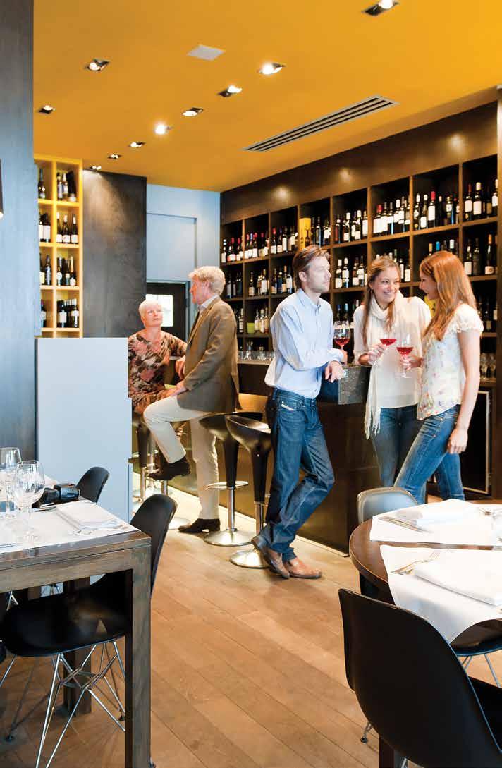
76 74
77 FAA-A + RZQG-L9V1/L(8)Y1 Wall mounted unit For rooms with no false ceilings nor free floor space Combination with Seasonal Smart ensures best in class quality, highest efficiency and performance Flat, stylish front panel blends easily within any interior décor and is easier to clean Can easily be installed in both new and refurbishment projects Unified indoor unit range for R-32 and R-410A Reduced energy consumption thanks to specially developed DC fan motor The air is comfortably spread up- and downwards thanks to 5 different discharge angles that can be programmed via the remote control Maintenance operations can be performed easily from the front of the unit Flexible to install as the largest casing only weighs 17kg and piping connection can be done at the bottom, left or right of the unit RZQG L9V1/L(8)Y1 FAA-A BRC1H51W BRP069A81 Indoor units Efficiency data FAA + RZQG 71A + 71L9V1 100A + 100L9V1 71A + 71L8Y1 100A + 100L8Y1 Cooling capacity Nom. kw Heating capacity Nom. kw Power input Cooling Nom. kw Heating Nom. kw Seasonal efficiency (according to EN14825) Cooling Energy efficiency class A++ Pdesign kw SEER Annual energy consumption kwh Heating (Average climate) Energy efficiency class A+ Pdesign kw SCOP/A Annual energy consumption kwh 2,205 3,562 2,205 3,562 Nominal efficiency EER COP Annual energy consumption kwh 1,000 1,315 1,000 1,315 Energy labeling Directive Cooling/Heating A/A Indoor unit FAA 71A 100A 71A 100A Dimensions Unit HeightxWidthxDepth mm 290x1,050x x1,200x x1,050x x1,200x240 Weight Unit kg Air filter Type - Fan Air flow rate Cooling Low/Medium/High m³/min 14.0/16 / /23 / /16 / /23 /26.0 Heating Low/Medium/High m³/min 14.0/16.0 / /23.0 / /16.0 / /23.0 /26.0 Sound power level Cooling dba Heating dba Sound pressure level Cooling Low/High dba 40/45 41/49 40/45 41/49 Heating Low/High dba 40/45 41/49 40/45 41/49 Control systems Wired remote control BRC1H51 / BRC1E53A / BRC1E53B / BRC1E53C / BRC1D52 Power supply Phase/Frequency/Voltage Hz/V 1~/50/ Outdoor unit RZQG 71L9V1 100L9V1 71L8Y1 100L8Y1 Dimensions Unit HeightxWidthxDepth mm 990x940x320 1,430x940x x940x320 1,430x940x320 Weight Unit kg Sound power level Cooling dba Sound pressure level Cooling Nom. dba Heating Nom. dba Operation range Cooling Ambient Min.~Max. CDB -15~50 Heating Ambient Min.~Max. CWB -20~15.5 Refrigerant Type/GWP R-410A/2,087.5 Charge kg/tco2eq 2.9/ / / /8.4 Piping connections Liquid/Gas mm 9.52/15.9 Piping length OU - IU Max. m System Equivalent m Chargeless m 30 Additional refrigerant charge kg/m See installation manual Level difference IU - OU Max. m 30.0 Power supply Phase/Frequency/Voltage Hz/V 1~/50/ N~/50/ Current - 50Hz Maximum fuse amps (MFA) A MFA is used to select the circuit breaker and the ground fault circuit interrupter (earth leakage circuit breaker). For more detailed information on each combination, please refer to the electrical data drawing. 75

78 FAA-A + RZQSG-L3/9V1/L(8)Y1 Wall mounted unit For rooms with no false ceilings nor free floor space Combination with Seasonal Classic ensures good value for money for all types of commercial applications. Flat, stylish front panel blends easily within any interior décor and is easier to clean Can easily be installed in both new and refurbishment projects Unified indoor unit range for R-32 and R-410A FAA-A RZQSG-L3/9V1,L(8)Y1 BRC1H51W BRP069A81 Efficiency data FAA + RZQSG 71A + 71L3V1 100A + 100L9V1 100A + 100L8Y1 Cooling capacity Nom. kw Heating capacity Nom. kw Power input Cooling Nom. kw Heating Nom. kw Seasonal efficiency (according to EN14825) 76 Cooling Energy efficiency class A+ Pdesign kw SEER Annual energy consumption kwh Heating (Average climate) Energy efficiency class A A+ Pdesign kw SCOP/A Annual energy consumption kwh 2,155 2,378 Nominal efficiency EER COP Annual energy consumption kwh 1,059 1,580 Energy labeling Directive Cooling/Heating A/A B/B Indoor unit FAA 71A 100A 100A Dimensions Unit HeightxWidthxDepth mm 290x1,050x x1,200x240 Weight Unit kg Air filter Type - Fan Air flow rate Cooling Low/Medium/High m³/min 14.0/16 / /23 /26.0 Heating Low/Medium/High m³/min 14.0/16.0 / /23.0 /26.0 Sound power level Cooling dba Heating dba Sound pressure level Cooling Low/High dba 40/45 41/49 Heating Low/High dba 40/45 41/49 Control systems Wired remote control BRC1H51 / BRC1E53A / BRC1E53B / BRC1E53C / BRC1D52 Power supply Phase/Frequency/Voltage Hz/V 1~/50/ Outdoor unit RZQSG 71L3V1 100L9V1 100L8Y1 Dimensions Unit HeightxWidthxDepth mm 770x900x x940x320 Weight Unit kg Sound power level Cooling dba Sound pressure level Cooling Nom./Silent operation dba 49/47 53/- Heating Nom. dba Operation range Cooling Ambient Min.~Max. CDB -15.0~46-15~46 Heating Ambient Min.~Max. CWB -15~15.5 Refrigerant Type/GWP R-410A/2,087.5 Charge kg/tco2eq 2.75/ /6.1 Piping connections Liquid/Gas mm 9.52/15.9 Piping length OU - IU Max. m 50 System Equivalent m 70 Chargeless m 30 Additional refrigerant charge kg/m See installation manual Level difference IU - OU Max. m Power supply Phase/Frequency/Voltage Hz/V 1~/50/ N~/50/ Current - 50Hz Maximum fuse amps (MFA) A MFA is used to select the circuit breaker and the ground fault circuit interrupter (earth leakage circuit breaker). For more detailed information on each combination, please refer to the electrical data drawing. Nominal cooling capacities are based on: indoor temperature: 27 CDB, 19 CWB, outdoor temperature: 35 CDB, equivalent refrigerant piping: 5m, level difference: 0m. Data for standard efficiency series Nominal heating capacities are based on: indoor temperature: 20 CDB, outdoor temperature: 7 CDB, 6 CWB, equivalent refrigerant piping: 5m, level difference: 0m. Data for standard efficiency series
79 FHA-A + RZQG-L9V1/L(8)Y1 Ceiling suspended unit For wide rooms with no false ceilings nor free floor space Combination with Seasonal Smart ensures best in class quality, highest efficiency and performance Ideal for comfortable air flow in wide rooms thanks to Coanda effect: up to 100 discharge angle Even rooms with ceilings up to 3.8m can be heated up or cooled down very easily without capacity loss Can easily be installed in both new and refurbishment projects Unified indoor unit range for R-32 and R-410A Can easily be mounted in corners and narrow spaces, as it only needs 30mm lateral service space Reduced energy consumption thanks to specially developed small tube heat exchanger, DC fan motor and drain pump 5 different fan speeds available for maximum comfort Stylish unit blends easily with any interior. The flaps close entirely when the unit is not operating and there are no air intake grilles visible RZQG L9V1/L(8)Y1 FHA-A BRC1H51W BRP069A81 Indoor units Efficiency data FHA + RZQG 71A + 100A + 125A + 140A + 71A + 100A + 125A + 140A + 71L9V1 100L9V1 125L9V1 140L9V1 71L8Y1 100L8Y1 125L8Y1 140LY1 Cooling capacity Nom. kw Heating capacity Nom. kw Power input Cooling Nom. kw Heating Nom. kw Seasonal efficiency (according to EN14825) Cooling Energy efficiency class A++ A+ - A++ A+ - Pdesign kw SEER Annual energy consumption kwh Heating (Average climate) Energy efficiency class A+ A++ A+ - A+ A++ A+ - Pdesign kw SCOP/A Annual energy consumption kwh 2,463 3,432 4,677-2,463 3,432 4,677 - Nominal efficiency EER COP Annual energy consumption kwh 890 1,245 1,790 2, ,245 1,790 2,025 Energy labeling Directive Cooling/Heating A/A Indoor unit FHA 71A 100A 125A 140A 71A 100A 125A 140A Dimensions Unit HeightxWidthxDepth mm 235x1,270x x1,590x x1,270x x1,590x690 Weight Unit kg Air filter Type Resin net Fan Air flow rate Cooling Low/Medium/High m³/min 14.0/17.0 / /24.0 / /27.0 / /29.0 / /17.0 / /24.0 / /27.0 / /29.0 /34.0 Heating Low/Medium/High m³/min 14.0/17.0 / /24.0 / /27.0 / /29.0 / /17.0 / /24.0 / /27.0 / /29.0 /34.0 Sound power level Cooling dba Sound pressure level Cooling Low/High dba 34/38 34/42 37/44 38/46 34/38 34/42 37/44 38/46 Heating Nom./High dba 36/38 38/42 41/44 42/46 36/38 38/42 41/44 42/46 Control systems Infrared remote control BRC7GA53 / BRC7GA56 Wired remote control BRC1H51 / BRC1E53A / BRC1E53B / BRC1E53C / BRC1D52 Power supply Phase/Frequency/Voltage Hz/V 1~/50/ Outdoor unit RZQG 71L9V1 100L9V1 125L9V1 140L9V1 71L8Y1 100L8Y1 125L8Y1 140LY1 Dimensions Unit HeightxWidthxDepth mm 990x940x320 1,430x940x x940x320 1,430x940x320 Weight Unit kg Sound power level Cooling dba Sound pressure level Cooling Nom. dba Heating Nom. dba Operation range Cooling Ambient Min.~Max. CDB -15~50 Heating Ambient Min.~Max. CWB -20~15.5 Refrigerant Type/GWP R-410A/2,087.5 Charge kg/tco2eq 2.9/ / / /8.4 Piping connections Liquid/Gas mm 9.52/15.9 Piping length OU - IU Max. m System Equivalent m Chargeless m 30 Additional refrigerant charge kg/m See installation manual Level difference IU - OU Max. m 30.0 Power supply Phase/Frequency/Voltage Hz/V 1~/50/ N~/50/ Current - 50Hz Maximum fuse amps (MFA) A MFA is used to select the circuit breaker and the ground fault circuit interrupter (earth leakage circuit breaker). For more detailed information on each combination, please refer to the electrical data drawing. 77
80 FHA-A + RZQSG-L3/9V1/L(8)Y1 Ceiling suspended unit For wide rooms with no false ceilings nor free floor space Combination with Seasonal Classic ensures good value for money for all types of commercial applications. Ideal for comfortable air flow in wide rooms thanks to Coanda effect: up to 100 discharge angle Even rooms with ceilings up to 3.8m can be heated up or cooled down very easily without capacity loss Can easily be installed in both new and refurbishment projects Unified indoor unit range for R-32 and R-410A FHA-A RZQSG71-125L3/9V1/L(8)Y1 BRC1H51W BRP069A81 Efficiency data FHA + RZQSG 71A + 71L3V1 100A + 125A + 140A + 100A + 125A + 100L9V1 125L9V1 140L9V1 100L8Y1 125L8Y1 140A + 140LY1 Cooling capacity Nom. kw Heating capacity Nom. kw Power input Cooling Nom. kw Heating Nom. kw Seasonal efficiency Cooling Energy efficiency class A+ - A+ - (according to Pdesign kw EN14825) SEER Annual energy consumption kwh Heating (Average climate) Energy efficiency class A A+ - A A+ - Pdesign kw SCOP/A Annual energy consumption kwh 2,727 2,722 2,654-2,722 2,654 - Nominal efficiency EER COP Annual energy consumption kwh 983 1,480 2,075 2,225 1,480 2,075 2,225 Energy labeling Directive Cooling/Heating A/A C/A B/B A/A C/A B/B Indoor unit FHA 71A 100A 125A 140A 100A 125A 140A Dimensions Unit HeightxWidthxDepth mm 235x1,270x x1,590x690 Weight Unit kg Air filter Type Resin net Fan Air flow rate Cooling Low/Medium/High m³/min 14.0/17.0 / /24.0 / /27.0 / /29.0 / /24.0 / /27.0 / /29.0 /34.0 Heating Low/Medium/High m³/min 14.0/17.0 / /24.0 / /27.0 / /29.0 / /24.0 / /27.0 / /29.0 /34.0 Sound power level Cooling dba Sound pressure level Cooling Low/High dba 34/38 34/42 37/44 38/46 34/42 37/44 38/46 Heating Nom./High dba 36/38 38/42 41/44 42/46 38/42 41/44 42/46 Control systems Infrared remote control BRC7GA53 / BRC7GA56 Wired remote control BRC1H51 / BRC1E53A / BRC1E53B / BRC1E53C / BRC1D52 Power supply Phase/Frequency/Voltage Hz/V 1~/50/ Outdoor unit RZQSG 71L3V1 100L9V1 125L9V1 140L9V1 100L8Y1 125L8Y1 140LY1 Dimensions Unit HeightxWidthxDepth mm 770x900x x940x320 1,430x940x x940x320 1,430x940x320 Weight Unit kg Sound power level Cooling dba Sound pressure level Cooling Nom./Silent operation dba 49/47 53/- 54/- 53/- 54/- 53/- Heating Nom. dba Operation range Cooling Ambient Min.~Max. CDB -15.0~46-15~46 Heating Ambient Min.~Max. CWB -15~15.5 Refrigerant Type/GWP R-410A/2,087.5 Charge kg/tco2eq 2.75/ / / / /8.4 Piping connections Liquid/Gas mm 9.52/15.9 Piping length OU - IU Max. m 50 System Equivalent m 70 Chargeless m 30 Additional refrigerant charge kg/m See installation manual Level difference IU - OU Max. m Power supply Phase/Frequency/Voltage Hz/V 1~/50/ N~/50/ Current - 50Hz Maximum fuse amps (MFA) A MFA is used to select the circuit breaker and the ground fault circuit interrupter (earth leakage circuit breaker). For more detailed information on each combination, please refer to the electrical data drawing. Nominal cooling capacities are based on: indoor temperature: 27 CDB, 19 CWB, outdoor temperature: 35 CDB, equivalent refrigerant piping: 5m, level difference: 0m. Data for standard efficiency series Nominal heating capacities are based on: indoor temperature: 20 CDB, outdoor temperature: 7 CDB, 6 CWB, equivalent refrigerant piping: 5m, level difference: 0m. Data for standard efficiency series

81 FHA-A + RXS-L(3) Split Ceiling suspended unit For wide rooms with no false ceilings nor free floor space Combination with split outdoor units is ideal for small retail, offices or residential applications Ideal for comfortable air flow in wide rooms thanks to Coanda effect: up to 100 discharge angle Even rooms with ceilings up to 3.8m can be heated up or cooled down very easily without capacity loss Can easily be installed in both new and refurbishment projects Unified indoor unit range for R-32 and R-410A FHA-A Indoor units RXS-L(3) BRC1H51W BRP069A81 Efficiency data FHA + RXS 35A + 35L3 50A + 50L 60A + 60L Cooling capacity Nom. kw Heating capacity Nom. kw Power input Cooling Nom. kw Heating Nom. kw Seasonal efficiency (according to EN14825) Cooling Energy efficiency class A++ A+ Pdesign kw SEER Annual energy consumption kwh Heating (Average climate) Energy efficiency class A+ A Pdesign kw SCOP/A Annual energy consumption kwh 981 1,578 1,705 Nominal efficiency EER COP Annual energy consumption kwh Energy labeling Directive Cooling/Heating A/A A/C Indoor unit FHA 35A 50A 60A Dimensions Unit HeightxWidthxDepth mm 235x960x x960x x1,270x690 Weight Unit kg Air filter Type Resin net Fan Air flow rate Cooling Low/Medium/High m³/min 10.0/11.5 / /12.0 / /15.0 /19.5 Heating Low/Medium/High m³/min 10.0/11.5 / /12.0 / /15.0 /19.5 Sound power level Cooling dba Sound pressure level Cooling Low/High dba 31/36 32/37 33/37 Heating Nom./High dba 34/36 35/37 Control systems Infrared remote control BRC7GA53 / BRC7GA56 Wired remote control BRC1H51 / BRC1E53A / BRC1E53B / BRC1E53C / BRC1D52 Power supply Phase/Frequency/Voltage Hz/V 1~/50/ Outdoor unit RXS 35L3 50L 60L Dimensions Unit HeightxWidthxDepth mm 550x765x x825x300 Weight Unit kg Sound power level Cooling dba Heating dba Sound pressure level Cooling Low/High dba -/48 44/48 46/49 Heating Low/High dba -/48 45/48 46/49 Operation range Cooling Ambient Min.~Max. CDB -10~46 Heating Ambient Min.~Max. CWB -15~18 Refrigerant Type R-410A GWP 2,087.5 Charge kg/tco2eq 1.2/ / /3.1 Piping connections Liquid OD mm 6.35 Gas OD mm Piping length OU - IU Max. m System Chargeless m 10 - Additional refrigerant charge kg/m 0.02 (for piping length exceeding 10m) (for piping length exceeding 10m) Level difference IU - OU Max. m Power supply Phase/Frequency/Voltage Hz/V 1~/50/ ~/50/ Current - 50Hz Maximum fuse amps (MFA) A - 79

82 AHQ-C + AZQS-B(8)V1/BY1 Ceiling suspended unit For wide rooms with no false ceilings nor free floor space Ideal solution for commercial spaces with no or narrow false ceilings Exclusively offered for pair applications Can easily be installed in both new and refurbishment projects Air filter removes airborne dust particles to ensure a steady supply of clean air Decrease of temperature variation by automatic fan speed selection or freely selectable 3-step fan speed. Easy installation and maintenance AHQ-C AZQS71BV1 ARCWLA Efficiency data AHQ + AZQS 71C + 71BV1 100C + 125C + 140C + 100B8V1 125B8V1 140B8V1 100C + 100BY1 125C + 125BY1 140C + 140BY1 Cooling capacity Nom. kw Heating capacity Nom. kw Power input Cooling Nom. kw Heating Nom. kw Seasonal efficiency Cooling Energy label B - B - (according to Pdesign kw EN14825) SEER Annual energy consumption kwh Heating (Average climate) Energy label A - A - Pdesign kw SCOP Annual energy consumption kwh 2, ,800-2,800 - Nominal efficiency EER COP Annual energy consumption kwh 1,120 1,810 2,300-1,810 2,300 - Energy label Cooling/Heating B/D D/B D/A - D/B D/A - Indoor unit AHQ 71C 100C 125C 140C 100C 125C 140C Dimensions Unit HeightxWidthxDepth mm 260x1,320x x1,538x x1,786x x1,902x x1,538x x1,786x x1,902x680 Weight Unit kg Air filter Type Removable / washable Fan - Air flow rate Cooling High/Nom./Low m³/min 23.8/21.3/ /27.8/ /30.6/ /39.1/ /27.8/ /30.6/ /39.1/28.3 Heating High/Nom./Low m³/min 23.8/21.3/ /27.8/ /30.6/ /39.1/ /27.8/ /30.6/ /39.1/28.3 Sound power level Cooling dba Heating dba Sound pressure level Cooling High/Nom./Low dba 49/48/46 52/47/46 52/50/49 56/53/46 52/47/46 52/50/49 56/53/46 Heating High/Nom./Low dba 49/48/46 52/47/46 52/50/49 56/53/46 52/47/46 52/50/49 56/53/46 Control systems Infrared remote control ARCWLA Wired remote control ARCWB Power supply Phase / Frequency / Voltage Hz / V 1~ / 50 / Outdoor unit AZQS 71BV1 100B8V1 125B8V1 140B8V1 100BY1 125BY1 140BY1 Dimensions Unit HeightxWidthxDepth mm 770x900x x940x320 1,430x940x x940x320 1,430x940x320 Weight Unit kg Sound power level Cooling dba Sound pressure level Cooling Nom. dba Heating Nom. dba Night quiet mode Level 1 dba Operation range Cooling Ambient Min.~Max. CDB -5~46 Heating Ambient Min.~Max. CWB -15~15.5 Refrigerant Type/Charge kg-tco²eq/gwp R-410A/2.75/5.7/2,087.5 R-410A/2.9/6.1/2,087.5 R-410A/4.0/8.4/2,087.5 R-410A/2.9/6.1/2,087.5 R-410A/4.0/8.4/2,087.5 Piping connections Liquid OD mm 9.52 Gas OD mm 15.9 Piping length OU - IU Max. m 50 System Equivalent m 70 Chargeless m 30 Additional refrigerant charge kg/m See installation manual Level difference IU - OU Max. m 30.0 Power supply Phase / Frequency / Voltage Hz / V 1~ / 50 / N~ / 50 / Current - 50Hz Maximum fuse amps (MFA) A (1) EER/COP according to Eurovent 2012, for use outside EU only (2) MFA is used to select the circuit breaker and the ground fault circuit interrupter (earth leakage circuit breaker). For more detailed information on each combination, please refer to the electrical data drawing.

83 81 Indoor units
84 FUA-A + RZQG-L9V1/L(8)Y1 4-way blow ceiling suspended unit Unique Daikin unit for high rooms with no false ceilings nor free floor space Combination with Seasonal Smart ensures best in class quality, highest efficiency and performance Even rooms with ceilings up to 3.5m can be heated up or cooled down very easily without capacity loss Can easily be installed in both new and refurbishment projects Unified range for R-32 and R-410A Individual flap control: flexibility to suit every room layout without changing the location of the unit! Stylish modern casing finished in pure white (RAL9010) and iron grey (RAL7011) blends easily with any interior Optimum comfort guaranteed with automatic air flow adjustment to the required load 5 different discharge angles between 0 and 60 can be programmed via the remote control Standard drain pump with 500mm lift increases flexibility and installation speed RZQG L9V1/L(8)Y1 FUA-A BRC1H51W BRP069A81 Efficiency data FUA + RZQG 71A + 71L9V1 100A + 100L9V1 125A + 125L9V1 71A + 71L8Y1 100A + 100L8Y1 125A + 125L8Y1 Cooling capacity Nom. kw Heating capacity Nom. kw Power input Cooling Nom. kw Heating Nom. kw Seasonal efficiency (according to EN14825) 82 Cooling Energy efficiency class A++ A+ A++ A+ Pdesign kw SEER Annual energy consumption kwh Heating (Average climate) Energy efficiency class A+ Pdesign kw SCOP/A Annual energy consumption kwh 2,534 3,516 4,456 2,534 3,516 4,456 Nominal efficiency EER COP Annual energy consumption kwh 840 1,230 1, ,230 1,770 Energy labeling Directive Cooling/Heating A/A A/B A/A A/B Indoor unit FUA 71A 100A 125A 71A 100A 125A Dimensions Unit HeightxWidthxDepth mm 198x950x950 Weight Unit kg Air filter Type Resin net Fan Air flow rate Cooling Low/Medium/High m³/min 16.0/19.5 / /25.5 / /26.5 / /19.5 / /25.5 / /26.5 /32.5 Heating Low/Medium/High m³/min 16.0/19.5 / /25.5 / /26.5 / /19.5 / /25.5 / /26.5 /32.5 Sound power level Cooling dba Heating dba Sound pressure level Cooling Low/High dba 35/41 39/46 40/47 35/41 39/46 40/47 Heating Low/High dba 35/41 39/46 40/47 35/41 39/46 40/47 Control systems Wired remote control BRC1H51 / BRC1E53A / BRC1E53B / BRC1E53C / BRC1D52 Power supply Phase/Frequency/Voltage Hz/V 1~/ 50/60 / /220 Outdoor unit RZQG 71L9V1 100L9V1 125L9V1 71L8Y1 100L8Y1 125L8Y1 Dimensions Unit HeightxWidthxDepth mm 990x940x320 1,430x940x x940x320 1,430x940x320 Weight Unit kg Sound power level Cooling dba Sound pressure level Cooling Nom. dba Heating Nom. dba Operation range Cooling Ambient Min.~Max. CDB -15~50 Heating Ambient Min.~Max. CWB -20~15.5 Refrigerant Type/GWP R-410A/2,087.5 Charge kg/tco2eq 2.9/ / / /8.4 Piping connections Liquid/Gas mm 9.52/15.9 Piping length OU - IU Max. m System Equivalent m Chargeless m 30 Additional refrigerant charge kg/m See installation manual Level difference IU - OU Max. m 30.0 Power supply Phase/Frequency/Voltage Hz/V 1~/50/ N~/50/ Current - 50Hz Maximum fuse amps (MFA) A MFA is used to select the circuit breaker and the ground fault circuit interrupter (earth leakage circuit breaker). For more detailed information on each combination, please refer to the electrical data drawing.
85 FUA-A + RZQSG-L3/9V1/L(8)Y1 4-way blow ceiling suspended unit Unique Daikin unit for high rooms with no false ceilings nor free floor space Combination with Seasonal Classic ensures good value for money for all types of commercial applications. Even rooms with ceilings up to 3.5m can be heated up or cooled down very easily without capacity loss Can easily be installed in both new and refurbishment projects Unified range for R-32 and R-410A Individual flap control: flexibility to suit every room layout without changing the location of the unit! 5 different discharge angles between 0 and 60 can be programmed via the remote control RZQSG-L3/9V1/L(8)Y1 FUA-A BRC1H51W BRP069A81 Indoor units Efficiency data FUA + RZQSG 71A + 71L3V1 100A + 100L9V1 125A + 125L9V1 100A + 100L8Y1 125A + 125L8Y1 Cooling capacity Nom. kw Heating capacity Nom. kw Power input Cooling Nom. kw Heating Nom. kw Seasonal efficiency (according to EN14825) Cooling Energy efficiency class A+ A A+ A Pdesign kw SEER Annual energy consumption kwh Heating (Average climate) Energy efficiency class A A+ A A+ A Pdesign kw SCOP/A Annual energy consumption kwh 2,273 2,654 2,764 2,654 2,764 Nominal efficiency EER COP Annual energy consumption kwh 1,060 1,480 2,265 1,480 2,265 Energy labeling Directive Cooling/Heating A/A D/B A/A D/B Indoor unit FUA 71A 100A 125A 100A 125A Dimensions Unit HeightxWidthxDepth mm 198x950x950 Weight Unit kg Air filter Type Resin net Fan Air flow rate Cooling Low/Medium/High m³/min 16.0/19.5 / /25.5 / /26.5 / /25.5 / /26.5 /32.5 Heating Low/Medium/High m³/min 16.0/19.5 / /25.5 / /26.5 / /25.5 / /26.5 /32.5 Sound power level Cooling dba Heating dba Sound pressure level Cooling Low/High dba 35/41 39/46 40/47 39/46 40/47 Heating Low/High dba 35/41 39/46 40/47 39/46 40/47 Control systems Wired remote control BRC1H51 / BRC1E53A / BRC1E53B / BRC1E53C / BRC1D52 Power supply Phase/Frequency/Voltage Hz/V 1~/ 50/60 / /220 Outdoor unit RZQSG 71L3V1 100L9V1 125L9V1 100L8Y1 125L8Y1 Dimensions Unit HeightxWidthxDepth mm 770x900x x940x320 Weight Unit kg Sound power level Cooling dba Sound pressure level Cooling Nom./Silent operation dba 49/47 53/- 54/- 53/- 54/- Heating Nom. dba Operation range Cooling Ambient Min.~Max. CDB -15.0~46-15~46 Heating Ambient Min.~Max. CWB -15~15.5 Refrigerant Type/GWP R-410A/2,087.5 Charge kg/tco2eq 2.75/ /6.1 Piping connections Liquid/Gas mm 9.52/15.9 Piping length OU - IU Max. m 50 System Equivalent m 70 Chargeless m 30 Additional refrigerant charge kg/m See installation manual Level difference IU - OU Max. m Power supply Phase/Frequency/Voltage Hz/V 1~/50/ N~/50/ Current - 50Hz Maximum fuse amps (MFA) A MFA is used to select the circuit breaker and the ground fault circuit interrupter (earth leakage circuit breaker). For more detailed information on each combination, please refer to the electrical data drawing. Nominal cooling capacities are based on: indoor temperature: 27 CDB, 19 CWB, outdoor temperature: 35 CDB, equivalent refrigerant piping: 5m, level difference: 0m. Data for standard efficiency series Nominal heating capacities are based on: indoor temperature: 20 CDB, outdoor temperature: 7 CDB, 6 CWB, equivalent refrigerant piping: 5m, level difference: 0m. Data for standard efficiency series 83
86 FVA-A+ RZQG-L9V1/L(8)Y1 Floor standing unit For commercial spaces with high ceilings Combination with seasonal smart ensures best in class quality, highest efficiency and performance Unified range for R-32 and R-410A Ideal solution for commercial and busy environments Decrease of temperature variation by automatic fan speed selection or freely selectable 3-step fan speed. Improved comfort as a result of better airflow distribution from the vertical out blow which allows manual adjustment of air outlet blades at the top of the unit. Selectable horizontal out blow to better suit the layout of the room (via wired remote controller BRC1E52) No optional adapter needed for DIII-connection, link your unit into the wider building management system. RZQG-L9V1/L(8)Y1 FVA-A BRC1H51W BRP069A81 Efficiency data FVA + RZQG 71A + 100A + 125A + 140A + 71A + 100A + 125A + 140A + 71L9V1 100L9V1 125L9V1 140L9V1 71L8Y1 100L8Y1 125L8Y1 140LY1 Cooling capacity Nom. kw Heating capacity Nom. kw Power input Cooling Nom. kw Heating Nom. kw Seasonal efficiency (according to EN14825) Cooling Energy efficiency class A++ A+ A++ A+ Pdesign kw SEER Annual energy consumption kwh Heating (Average climate) Energy efficiency class A+ A A+ A Pdesign kw SCOP/A Annual energy consumption kwh 2,189 3,767 4,088 2,189 3,767 4,088 Nominal efficiency EER COP Annual energy consumption kwh 1,010 1,245 1,870 2,085 1,010 1,245 1,870 2,085 Energy labeling Directive Cooling/Heating A / A A / A A / A A / A A / A A / A Indoor unit FVA 71A 100A 125A 140A 71A 100A 125A 140A Dimensions Unit HeightxWidthxDepth mm 1,850x600x270 1,850x600x350 1,850x600x270 1,850x600x350 Weight Unit kg Air filter Type Resin net Fan - Air flow rate Cooling High/Low m³/min 18/14 28/22 28/24 30/26 18/14 28/22 28/24 30/26 Heating High/Low m³/min 18/14 28/22 28/24 30/26 18/14 28/22 28/24 30/26 Sound power level Cooling dba Heating dba Sound pressure level Cooling High/Low dba 43/38 50/44 51/46 53/48 43/38 50/44 51/46 53/48 Heating High/Low dba 43/38 50/44 51/46 53/48 43/38 50/44 51/46 53/48 Refrigerant Type R-32 / R-410A Control systems Wired remote control BRC1H51 / BRC1E53A / BRC1E53B / BRC1E53C / BRC1D52 Power supply Phase / Frequency / Voltage Hz / V 1~ / 50/60 / /220 Outdoor unit RZQG 71L9V1 100L9V1 125L9V1 140L9V1 71L8Y1 100L8Y1 125L8Y1 140LY1 Dimensions Unit HeightxWidthxDepth mm 990x940x320 1,430x940x x940x320 1,430x940x320 Weight Unit kg Sound power level Cooling dba Sound pressure level Cooling Nom. dba Heating Nom. dba Operation range Cooling Ambient Min.~Max. CDB -15~50 Heating Ambient Min.~Max. CWB -20~15.5 Refrigerant Type/GWP R-410A/2,087.5 Charge kg/tco2eq 2.9/ / / /8.4 Piping connections Liquid/Gas mm 9.52/15.9 Piping length OU - IU Max. m System Equivalent m Chargeless m 30 Additional refrigerant charge kg/m See installation manual Level difference IU - OU Max. m 30.0 Power supply Phase/Frequency/Voltage Hz/V 1~/50/ N~/50/ Current - 50Hz Maximum fuse amps (MFA) A (1) EER/COP according to Eurovent 2012, for use outside EU only (2) MFA is used to select the circuit breaker and the ground fault circuit interrupter (earth leakage circuit breaker). For more detailed information on each combination, please refer to the electrical data drawing. 84
87 FVA-A + RZQSG-L3/L9V1/L(8)Y1 Floor standing unit For commercial spaces with high ceilings Combination with Seasonal Classic ensures good value for money for all types of commercial applications Unified range for R-32 and R-410A Ideal solution for commercial and busy environments Decrease of temperature variation by automatic fan speed selection or freely selectable 3-step fan speed. Improved comfort as a result of better airflow distribution from the vertical out blow which allows manual adjustment of air outlet blades at the top of the unit. Selectable horizontal out blow to better suit the layout of the room (via wired remote controller BRC1E52) No optional adapter needed for DIII-connection, link your unit into the wider building management system. RZQSG-L3/9V1/L(8)Y1 FVA-A BRC1H51W BRP069A81 Indoor units Efficiency data FVA + RZQSG 71A + 71L3V1 100A + 125A + 140A + 100A + 100L9V1 125L9V1 140L9V1 100L8Y1 125A + 25L8Y1 140A + 140LY1 Cooling capacity Nom. kw Heating capacity Nom. kw Power input Cooling Nom. kw Heating Nom. kw Seasonal efficiency Cooling Energy efficiency class A A (according to Pdesign kw EN14825) SEER Annual energy consumption kwh Heating (Average climate) Energy efficiency class A A+ A A+ A Pdesign kw SCOP/A Annual energy consumption kwh 2,297 2,654 2, Nominal efficiency EER COP Annual energy consumption kwh 1,060 1,480 2,135 2,225 1,480 2,135 2,225 Energy labeling Directive Cooling/Heating A / A A / B A / A C / B Indoor unit FVA 71A 100A 125A 140A 100A 125A 140A Dimensions Unit HeightxWidthxDepth mm 1,850x600x270 1,850x600x350 Weight Unit kg Air filter Type Resin net Fan - Air flow rate Cooling High/Low m³/min 18/14 28/22 28/24 30/26 28/22 28/24 30/26 Heating High/Low m³/min 18/14 28/22 28/24 30/26 28/22 28/24 30/26 Sound power level Cooling dba Heating dba Sound pressure level Cooling High/Low dba 43/38 50/44 51/46 53/48 50/44 51/46 53/48 Heating High/Low dba 43/38 50/44 51/46 53/48 50/44 51/46 53/48 Refrigerant Type R-32 / R-410A Control systems Wired remote control BRC1H51 / BRC1E53A / BRC1E53B / BRC1E53C / BRC1D52 Power supply Phase / Frequency / Voltage Hz / V 1~ / 50/60 / /220 Outdoor unit RZQSG 71L3V1 100L9V1 125L9V1 140L9V1 100L8Y1 125L8Y1 140LY1 Dimensions Unit HeightxWidthxDepth mm 770x900x x940x320 1,430x940x x940x320 1,430x940x320 Weight Unit kg Sound power level Cooling dba Sound pressure level Cooling Nom./Silent operation dba 49/47 53/- 54/- 53/- 54/- 53/- Heating Nom. dba Operation range Cooling Ambient Min.~Max. CDB -15.0~46-15~46 Heating Ambient Min.~Max. CWB -15~15.5 Refrigerant Type/GWP R-410A/2,087.5 Charge kg/tco2eq 2.75/ / / / /8.4 Piping connections Liquid/Gas mm 9.52/15.9 Piping length OU - IU Max. m 50 System Equivalent m 70 Chargeless m 30 Additional refrigerant charge kg/m See installation manual Level difference IU - OU Max. m Power supply Phase/Frequency/Voltage Hz/V 1~/50/ N~/50/ Current - 50Hz Maximum fuse amps (MFA) A (1) EER/COP according to Eurovent 2012, for use outside EU only (2) MFA is used to select the circuit breaker and the ground fault circuit interrupter (earth leakage circuit breaker). For more detailed information on each combination, please refer to the electrical data drawing. 85
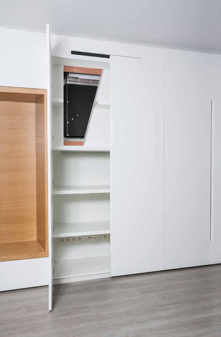
88 86
89 FNA-A + RXS-L(3) Split Concealed floor standing unit Designed to be concealed in walls Combination with split outdoor units is ideal for small retail, offices or residential applications Unified range for R-32 and R-410A Ideal for installation in offices, hotels and residential applications Blends unobtrusively with any interior design: only the suction and discharge grills are visible Its low height (620 mm) enables the unit to fit perfectly beneath a window Requires very little installation space as the depth is only 200mm High ESP allows flexible installation FNQ-A Indoor units RXS35L3 BRC1H51W BRP069A81 Efficiency data FNA + RXS 25A + 25L3 35A + 35L3 50A + 50L 60A + 60L Cooling capacity Nom. kw Heating capacity Nom. kw Power input Cooling Nom. kw Heating Nom. kw Seasonal efficiency (according to EN14825) Cooling Energy efficiency class A+ A Pdesign kw SEER Annual energy consumption kwh Heating (Average climate) Energy efficiency class A+ Pdesign kw SCOP/A Annual energy consumption kwh 925 1,002 1,369 1,548 Nominal efficiency EER COP Annual energy consumption kwh ,119 Energy labeling Directive Cooling/Heating A / A B / B A / C D / D Indoor unit FNA 25A 35A 50A 60A Dimensions Unit HeightxWidthxDepth mm 620 / 720(2)x750x / 720(2)x1,150x200 Weight Unit kg Air filter Type Resin net Fan - Air flow rate Cooling High/Low m³/min 8.7/ /13.5 Heating High/Low m³/min 8.7/ /13.5 Fan - External static pressure High/Nom./Maximum available/high Pa 48/30/- 49/40/- Sound power level Cooling dba Sound pressure level Cooling High/Low dba 33/28 36/30 Heating High/Low dba 33/28 36/30 Refrigerant Type R-32 / R-410A Control systems Infrared remote control BRC4C65 Wired remote control BRC1H51 / BRC1E53A / BRC1E53B / BRC1E53C / BRC1D52 Power supply Phase / Frequency / Voltage Hz / V 1~ / 50/60 / /220 Outdoor unit RXS 25L3 35L3 50L 60L Dimensions Unit HeightxWidthxDepth mm 550x765x x825x300 Weight Unit kg Sound power level Cooling dba Heating dba Sound pressure level Cooling Low/High dba -/46 -/48 44/48 46/49 Heating Low/High dba -/47 -/48 45/48 46/49 Operation range Cooling Ambient Min.~Max. CDB -10~46 Heating Ambient Min.~Max. CWB -15~18 Refrigerant Type R-410A GWP 2,087.5 Charge kg/tco2eq 1.0/ / / /3.1 Piping connections Liquid OD mm 6.35 Gas OD mm Piping OU - IU Max. m length System Chargeless m 10 - Additional refrigerant charge kg/m 0.02 (for piping length exceeding 10m) (for piping length exceeding 10m) Level difference IU - OU Max. m Power supply Phase/Frequency/Voltage Hz/V 1~/50/ ~/50/ Current - 50Hz Maximum fuse amps (MFA) A - (1) EER/COP according to Eurovent 2012, for use outside EU only (2) Including installation legs (3) MFA is used to select the circuit breaker and the ground fault circuit interrupter (earth leakage circuit breaker). For more detailed information on each combination, please refer to the electrical data drawing. 87
90 SKY AIR ALPHA-SERIES SKY AIR ADVANCE-SERIES SUPER INVERTER 88
91 Outdoor units A range of industry leading technology outdoor units Outdoor Unit Products overview 90 Benefits overview 91 Sky Air pair, twin, triple, double twin applications 92 Pair solution range 102 RZAG-MV1/MY1 102 RZASG-MV1/MY1 103 AZAS-MV1/MY1 104 range 105 RZQG-L9V1/L(8)Y1 Seasonal Smart 105 Twin, triple, double twin solution RZQSG-L3/L9V1/LY1 106 AZQS-B8V1/BY1 107 RZQ-C 108 Multi model and VRV range 109 Connect up to 5 different Sky Air units to our multi range Connect up to 9 different Sky Air units to our Sky Air VRV range For more info split en VRV installer catalogue Multi solution 89
92 Outdoor units Products overview outdoor units Pair, twin, triple & double twin application Capacity clas System Type Model Product name PG kw 9.5 kw 12.1 kw 13.4 kw RZAG-MV Industry leading technology for commercial applications --Dedicated solution for infrastructure cooling --Variable Refrigerant Temperature --Maximum piping length up to 85m --Replacement technology --Extended operation range down to -20 C in both heating and cooling --Pair, twin, triple and double twin application RZAG-MY1 102 RZASG-MV1 103 Air cooled Heat pump --Technology and comfort combined for commercial applications --Very compact and easy to install outdoor units --Maximum piping length up to 50m --Replacement technology --Operation range down to -15 C both cooling and in heating --Pair, twin, triple and double twin application RZASG-MY1 103 AZAS-MV Ideal solution for busy environments and small shops --Very compact and easy to install outdoor units --Maximum piping length up to 30m --Replacement technology --Easy-to-mount outdoor units: roof, terrace or wall --Exclusively offered for pair applications AZAS-MY1 104 Pair, twin, triple & double twin application Capacity class System Type Model Product name PG Air cooled Heat pump --Industry leading technology for commercial applications --Dedicated solution for infrastructure cooling --Variable Refrigerant Temperature --Maximum piping length up to 75m --Re-use technology --Extended operation range down to -20 C in heating and -15 C in cooling --Pair, twin, triple and double twin application --Technology and comfort combined for commercial applications --Maximum piping length up to 50m --Re-use technology --Operation range down to -15 C both cooling and in heating --Pair, twin, triple and double twin application Standard outdoor unit --Ideal solution for busy environments and small shops --Easy-to-mount outdoor units: roof, terrace or wall --Outdoor units with swing or scroll compressor --Exclusively offered for pair applications -- RZQG-L9V1 105 RZQG-L(8)Y1 105 RZQSG-L3/ L9V1 106 RZQSG-L(8)Y1 106 AZQS-B8V1 107 AZQS-BY Packaged system for commercial applications --For large commercial applications --Re-use technology --Pair, twin, triple and double twin applications RZQ-C
93 Benefits overview outdoor units Outdoor units RZAG-MV1 / MY1 RZASG-MV1 / MY1 AZAS-MV1 / MY1 We care icons Comfort RZQSG-L3/9V1/L(8)Y1 RZQG-L9V1/ L(8)Y1- AZQS- B8V1/BY1 RZQ-C Seasonal efficiency - Seasonal efficiency gives a more realistic indication on how efficient air Smart use of energy conditioners operate over an entire heating or cooling season. Inverter technology In combination with inverter controlled outdoor units Replacement Quick and quality system replacement in the most cost effective way technology Night quiet Lowers the operation sound of the outdoor unit automatically. Auto cooling-heating Automatically selects cooling or heating mode to achieve the set changeover temperature. Outdoor Unit Other functions Variable refrigeration temperature Twin/triple/double twin application Multi model application Swing compressor Guaranteed operation down to -20 C Infrastructure cooling The intelligent systems ensures highest energy savings with additional comfort to better suit application requirements. 2, 3 or 4 indoor units can be connected to only 1 outdoor unit even if they have different capacities. All indoor units operate within the same mode (cooling or heating) from one remote control. Up to 5 indoor units (even different capacities) can be connected to a single outdoor unit. All indoor units can individually be operated within the same mode. Outdoor units are fitted with a swing compressor, renowned for its low noise and high reliability Daikin is suitable for all climates, even withstanding severe winter conditions with an operation range down to -20 C. For high sensible, infrastructure cooling applications, dedicated infrastructure cooling settings and allowing asymmetric combinations enhance the system s reliability. Technical benefit overview Compact single fan casing on the entire range Maximum piping length 85 m 50 m 30 m Pivoting front plate 7 segment display Increased factory charge Integrated leak check Refrigerant bottom plate pass Specially deveoloped R-32 swing compressor Refrigerant cooled PCB Intelligent Tablet controller - Online controller app 91

94 The new Sky Air A-series, built for all Sky Air applications Lighter and more compact units for easy installation. Unique single fan range up to 14 kw New replacement technology A quicker, easier and more reliable approach when replacing existing systems Hepta filtration ensures reliable operation without the need for pipe cleaning 770 mm Full range below 1m in height! 990 mm Increased piping length up to 85m Widest operation range -20C DB 52 C DB -20C WB 15.5 C WB Cooling operation from -20 C to 52 C Heating operation down to -20 C Faster installation with up to 40m pre-charged pipe Up to 60% of applications can be installed without additional refrigerant charge Redesigned pivoting front plate for easy access to vital system components 92


95 New 7-segment display to view errors and systems settings Guaranteed reliable performance in all weather conditions bottom plate refrigerant pass New refrigerant passes Lower part of the outdoor heat exchanger and drain holes are kept completely open and free of ice allowing ice water to evacuate perfectly, eliminating all risk of ice build-up. Refrigerant cooled PCB s Reliable and stable cooling, independent from outdoor conditions Temperature around El. Box Others Daikin Outdoor Unit Integrated leak-check function reduces on-site checks and improves reliability Reliable refrigerant cooled PCB s Time Daikin Sky Air A-series uses patented Daikin technology at the heart of the system 3-row heat exchanger Unqiue 3-row heat exchanger to allow compact casing up to 14 kw Jigsaw curved propeller Curved discharge grill and Jigsaw curved propeller for minimal turbulence and optimal airflow Bottom plate and heat exchanger refrigerant pass Drain holes are kept ice free Guaranteed operation down to -20 C Refrigerant cooled PCB Daikin swing compressor Integration of main moving parts into one component No abrasion or friction No refrigerant leakages No temperature rise because of leakage High compressor efficiencies Increased system life span UNIQUE & PATENTED TECHNOLOGY 93


96 Outdoor units Replacement technology The quick and quality way of upgrading R-22 and R-410A systems Benefits to increase your profit Optimise your business Less installation time Tackle more projects in less time thanks to faster installation. It is more profitable than replacing the full system with new piping. Lower installation costs Reducing installation costs enables you to offer customers the most cost-effective solution and improve your competitive edge. Replace non-daikin systems It is a trouble-free replacement solution for Daikin systems and for systems made by other manufacturers. Easy as one-two-three A simple solution for replacement technology enables you to handle more projects for more customers in less time and offer them the best price! Everybody gains. How does it work? The Daikin low-cost upgrade solution! Replace indoor units Contact your local dealer to check compatibility in case you need to keep the indoor units. The benefits will convice your customer To prevent unexpected breakdown To lower running costs To protect the environment To improve comfort Your copper pipes will last for multiple generations - copper pipes used in air conditioning systems tested by Daikin will last over 60 years after installation. - Japan/China have replaced with VRV Q-series already 10 years ago! Umeda Center Building, Japan - original A/C system: 20 years in use - replacement with VRV Q-series: capacity up from 1620HP to 2322HP - SHASE renewal award: Unique technologies 2013 (1st) Cleaning free piping re-usage thanks to unique hepta filtering for maximum particle reduction LPS HPS-A Replace outdoor units 5 Learn more about Daikin replacement solutions at replacement-technology.html New expansion valve needle material, with high corrosion resistance New type oil for maximum system protection 94
97 New simplified replacement procedure with Sky Air A-series outdoor units How does it work? Outdoor units 1 Evaluate if the pipe work can be re-used Check if the piping installation is according to standards, that there no fractures or damages and that liquid and gas pipe have separate insulation Verify pipe thickness Outdoor Unit Outside diameter (mm) Material Thickness (mm) 6.4 o o o o /2H 1.0 o: annealed - 1/2H: half hard Sky Air Verify piping diameter Liquid Gas kW x x x kW x x o kW Refrigerant pipe size-up required. Please consult the RZQ-C installation manual. Verify the piping length Possible (Standard condition) o Possible (With no impact on chargeless length and total length) Possible (With impact on chargeless length and total length ) x Impossible RZAG Liquid pipe (mm) / (15) m Chargeless (equivalent) / (50) m / (20) m / (15) m Max. total length (equivalent) / (75) m 85 / (100) m / (35) m 35 / (45) m Check if any operation history affects the ability to re-use the pipes(systems with a pipe length up to 35m, can always re-use exisiting pipe work when using a new Sky Air A-series model) System to be replaced System condition Piping length R-22 (mineral oil) R-410A (synthetic oil) R-32 (synthetic oil) Unit is operating (pump down can be performed) Pump down operation impossibility or compressor malfunction Unit is operating (pump down can be performed) Pump down operation impossibility or compressor malfunction Unit is operating (pump down can be performed) Pump down operation impossibility or compressor malfunction No restrictions Below 35 m Above 35 m No restrictions Below 35 m Above 35 m No restrictions Below 35 m Above 35 m R-32 Sky Air A-series (RZAG/RZASG/AZAS) o o o Cleaning-free piping re-use o Cleaning of field piping or replacement of field piping is required The Flare connection MUST be redone by using the flare nut included with the new outdoor unit 2 Evaluate if the wiring can be re-used Check if the wiring meets current standard and the specificaton of the new unit and that there is no damage or scratches note: For general installation guidelines and requirements please check the installation manual of the specific outdoor model 95

98 Outdoor units Variable Refrigerant Temperature The ultimate customer experience Increases air discharge temperature and eliminates cold drafts! Increased customer comfort and reduced energy consumption! Weather dependent limitation Two defined outdoor temperatures trigger the changeover of the Te Between those two trigger values the Te will change linear The system automatically increases its evaporating temperature (Te) when the gap between the actual indoor temperature (Tin) and the setpoint (Tset) is becoming smaller Possibility to customize the evaporating limits Min. Te1 Min. Te2 Quick cooling (selected on remote control) Linear Te limit Outdoor t trigger values Depending on the gap between indoor t and set point the Te will be increased or decreased Ta Case study: Clothing shop in the Brussels area Two pair systems are installed in the same zone allowing comparison Outdoor Indoor Deco panel Control System 1 = VRT enabled (Alpha 1) RZAG125MV1 FCAG125A BYCQ140D 1 x BRC1E53A System 2 = Factory settings (Alpha 2) RZAG125MV1 FCAG125A BYCQ140D More energy efficient: up to 20% lower energy consumption Average energy consumption over 5 months of operation VRT enabled No VRT Apr May Jun Jul Aug Improved comfort: higher discharge temperatures More stable and continuous operation Average discharge temperature increased with 3~4 C Td Alpha 01 [VRT enabled] Alpha 02 [Default set] 0.0 t 96

99 RELIABLE, CONTINUOUS OPERATION Infrastructure cooling solution Infrastructure cooling Daikin is the world leader when it comes to cooling. With over 90 years of innovation and engineering expertise in specialised cooling, Daikin offers a Sky Air solution that is reliable, efficient and flexible to meet the demanding needs of infrastructure cooling environments. Outdoor Unit Reliable Guaranteed system operation: Oversized indoor units boost cooling capacity and prevent freeze-ups on the indoor side Wide operating range envelope: operation range in cooling down to -20 C and up to +52 C Efficient Optimum return on investment: Lowers running costs by using highly efficient direct expansion cooling systems Lower running costs compared to other DX systems and water based chillers. Minimises environmental impact with A++ energy labels Reduces mechanical cooling and energy consumption with the free cooling option for single phase systems Flexible Scalable in capacity Improved infrastructure control and management Lower physical footprint since no floor space is occupied Wide range of indoor units to suit application preferences (ceiling suspended cassettes, wall mounted indoors, concealed ceiling ducted type indoors) UNIQUE Dedicated system combinations UNIQUE 2-step solution for system selection Benefits 1. Boost the heat transfer capacity of the indoor system 2. Ability to work with higher evaporation temperatures (Te) avoids downtime and enables continuous operation 3. Official energy labels for indoor and outdoor system combinations provide standardized and reliable performance data Benefits 1. Daikin makes the system selection procedure easy and reliable by providing detailed capacity tables based on extensive testing. 2. Choose the best product combination that meets end-user requirements UNIQUE Efficient cooling Benefits 1. Free cooling: optimum energy efficiency using cold ambient air 2. Widest range of indoor systems with best in class energy efficiency 3. Wide indoor and outdoor operation range, reliable performance even in extreme conditions UNIQUE Flexible control Benefits 1. Optimal backup supported by duty rotation control, automatic backup activation and remote alarms 2. Guaranteed continuous operation from extended compressor limits 3. Controller settings to adapt to specific infrastructure cooling environment conditions 4. Fewer start/stop cycles Infrastructure cooling solution For server rooms, telecom shelters, laboratories, IT applications Find out more in our infrastructure cooling brochure 97
100 Infrastructure cooling solution Boosted capacity indoor systems High reliability at lower running costs for infrastructure cooling Split air conditioning systems for normal comfort cooling applications usually combine indoor systems with matching capacities, or multiple indoor systems with capacities lower than the outdoor system s capacity. This works because the indoor system s cooling capacity is sufficient to handle the higher humidity conditions and varying indoor temperature requirements that are common in a normal living environment. Applying this design logic to infrastructure cooling environments can lead to risky situations that might compromise overall system reliability and frequent downtimes of 15 minutes. Indoor systems for infrastructure cooling environments need enhanced capabilities for continuous heat transfer because they work harder to extract energy by cooling dry air. Daikin recommends and offers asymmetric combinations (boosted capacity indoor combinations: e.g. 71 class outdoor class indoor). You can now confidently combine indoor systems with higher capacities than the outdoor system. This will boost heat transfer inside the technology or server room environments. Infrastructure cooling application system solutions traditional solution Symmetric indoor-outdoor system combination Te kw RH% dedicated solution Te kw RH% Between 20-40% sensible capacity increase 6 4 Evaporating Temperature 6 4 Capacity Relative Humidity: Capacity: Evaporating temp: Time reduces over time reduced drops to compensate reduced capacity too low Te can lead to freeze-up prevention, causing system downtime 6 4 Evaporating Temperature 6 4 Capacity Improved solution Time Boosted capacity indoors increase the heat transfer capacity at low relative humidity Allows the system to operate with higher Te, guaranteeing continuous operation and reducing unwanted dehumidification Low humidity + Low ambient environment Outside temperature Ta -5 C Set-point 22 C Humidity 35 % Indoor wet-bulb temperature 13 C EER traditional solution 100% improved solution 82% 18% SAVINGS 18% savings on running cost traditional solution 71 class outdoor with 71 class indoor Total Capacity (TC) 5.63 kw Sensible Heat Capacity (SHC) 4.28 kw Power Input (PI) 2 kw Co-efficient of Power Input (CPI) 0.39 Corrected PI 0.78 kw EER* 5,5 dedicated system combination solution 71 class outdoor with 100 class indoor Total Capacity (TC) 6,02 kw Sensible Heat Capacity (SHC) 6,02 kw Power Input (PI) 2 kw Co-efficient of Power Input (CPI) 0,45 Corrected PI 0.90 kw EER* 6,7 Sensible Heat Capacity increases 20-40% with dedicated system combination. *EER = (SHC/Corrected PI) 98
101 Infrastructure cooling solution 2-Step solution for system selection High reliability for infrastructure cooling UNIQUE Select your infrastructure cooling system in 2 steps No humidity generation in room (eg: Server room) IT room requires 22 C inside. It will have 7kW of sensible cooling demand, and no latent cooling demand (no humidity generation) throughout the year. Ceiling suspended indoor unit is the customer's preference for the server room. Indoor temperature = 22 CDB Sensible cooling demand (SHC) = 7 kw STEP 1 Determine requested indoor conditions and required cooling demand (Sensible and Total capacity) Some humidity source in room (eg: Laboratory) Lab requires 22 C inside. It will have 9 kw of sensible cooling demand, and some humidity generation in the room (est. indoor humidity level 42%). Wall mounted indoor unit is the customer s preference for the laboratory. Indoor temperature = 22 CDB Indoor Relative Humidity (RH%) = 42%** Outdoor Unit Latent cooling demand (LC) = 0 kw* Sensible cooling demand (SHC) = 9 kw Total cooling demand (TC) = SHC + LC = 7 kw Latent cooling demand (LC) = 0.9 kw Outdoor temperature operating range = -15 C ~ +40 C Total cooling demand (TC) = SHC + LC = 9.9 kw Most stringent outdoor unit capacity condition = -15 C Outdoor temperature operating range = -10 C ~ +40 C Most stringent outdoor unit capacity condition = -10 C solution Boosted capacity indoor combination with 10kW outdoor system. 100 class outdoor class indoor Total capacity = 7.48 kw Sensible capacity = 7.48 kw Power input = 0.42 x 2.49 = 1.04 kw * If there is no latent cooling demand, look for conditions where TC = SHC, since no more dehumidification will occur and thus the indoor environment will stabilize. When TC > SHC and there is no humidity generation, the indoor humidity will gradually decrease. STEP 2 Select the system combination from the given table, where the system s sensible and total capacity meets the cooling demand at the requested indoor and outdoor temperatures. solution Boosted capacity indoor combination with 12.5kW outdoor system. 125 class outdoor with twin 71 class indoor Total capacity = kw Sensible capacity = 9.34 kw Power input = 0.48 x 3.69 = 1.78 kw ** System capacity at 42%RH (14,2 CWB) can be found by interpolation between 13 CWB (35%) and 15 CWB (48%). Combination table for boosted capacity indoor systems Sky Air Wall mounted Ceiling suspended unit Concealed ceiling unit with medium ESP Concealed ceiling unit 4-way blow ceiling mounted cassette Floor standing unit Fully flat cassette High COP, round flow cassette Round flow cassette Model FAA71 FAA100 FHA35 FHA50 FHA60 FHA71 FHA100 FHA125 FHA140 FBA35 FBA50 FBA60 FBA71 FBA100 FBA125 FBA140 FDXM35 FDXM50 FDXM60 FUA71 FUA100 FUA125 FVA71 FVA100 FVA125 FVA140 FFA35 FFA50 FFA60 FCAHG71 FCAHG100 FCAHG125 FCAHG140 FCAG35 FCAG50 FCAG60 FCAG71 FCAG100 FCAG125 FCAG140 RZAG71 / RZQG71 P 3 2 P 3 2 P 3 2 P P 3 2 P 3 2 P RZAG100 / RZQG P P P P P RZAG125 / RZQG P P P P P RZAG140 / RZQG P P P P P Possible combinations: P = Pair 2 = Twin 3 = Triple 4 = Double Twin Notes: The capacities in the table are combined capacities (multiple units operating simultaneously) and not individual indoor unit capacities. When combining multiple indoor units, designate the master unit as the unit whose remote controller is equipped with the most functions. Refer to the option list when selecting the correct refnet kit required to install a multi-combination. 99
102 Infrastructure cooling solution Performance characteristics for boosted capacity indoor combinations Boosted capacity indoors with 7kW outdoor system RZAG71MV1/MY1 Outdoor temperature [ C DB] Indoor TC SHC CPI TC SHC CPI TC SHC CPI TC SHC CPI TC SHC CPI TC SHC CPI TC SHC CPI TC SHC CPI TC SHC CPI TC SHC CPI TC SHC CPI TC SHC CPI RH [%] CWB CDB kw kw - kw kw - kw kw - kw kw - kw kw - kw kw - kw kw - kw kw - kw kw - kw kw - kw kw - kw kw D098206A PAIR FAA100 FHA100 FBA100 FUA100 FVA100 FCAHG100 FCAG100 Cooling TWIN FHA50 x 2 FBA50 x 2 FDXM50 x 2 FFA50 x 2 FCAG50 x 2 Cooling TRIPLE FHA35 x 3 FBA35 x 3 FDXM35 x 3 FFA35 x 3 FCAG35 x 3 Cooling Boosted capacity indoors with 10kW outdoor system RZAG100MV1/MY1 Note : blue cells contain preliminary data Outdoor temperature [ C DB] Indoor TC SHC CPI TC SHC CPI TC SHC CPI TC SHC CPI TC SHC CPI TC SHC CPI TC SHC CPI TC SHC CPI TC SHC CPI TC SHC CPI TC SHC CPI TC SHC CPI RH [%] CWB CDB kw kw - kw kw - kw kw - kw kw - kw kw - kw kw - kw kw - kw kw - kw kw - kw kw - kw kw - kw kw D098207A PAIR FHA140 FBQA140 FVA140 FCAHG140 FCAG140 Cooling TWIN FAA71 x 2 FHA71 x 2 FBA71 x 2 FUA71 x 2 FCAHG71 x 2 FCAG71 x 2 Cooling TRIPLE FHQA50 x 3 FBA50 x 3 FDXM50 x 3 FFA50 x 3 FCAG50 x 3 Cooling DOUBLE TWIN FHA35 x 4 FBA35 x 4 FDXM35 x 4 FFA35 x 4 FCAG35 x 4 Cooling Note : blue cells contain preliminary data Symbols 100 TC Maximum total cooling capacity [kw] SHC Sensible heat capacity [kw] CPI Coefficient of the power input PI Power input [kw] compressor + indoor and outdoor fan motors RH Relative humidity [%]
103 Infrastructure cooling solution Boosted capacity indoors with 12.5kW outdoor system RZAG125MV1/MY1 Outdoor temperature [ C DB] Indoor TC SHC CPI TC SHC CPI TC SHC CPI TC SHC CPI TC SHC CPI TC SHC CPI TC SHC CPI TC SHC CPI TC SHC CPI TC SHC CPI TC SHC CPI TC SHC CPI RH [%] CWB CDB kw kw - kw kw - kw kw - kw kw - kw kw - kw kw - kw kw - kw kw - kw kw - kw kw - kw kw - kw kw D098208A Outdoor Unit PAIR FHA140 FBA140 FVA140 FCAHG140 FCAG140 Cooling TWIN FAA71 x 2 FHA71 x 2 FBA71 x 2 FUA71 x 2 FCAHG71 x 2 FCAG71 x 2 Cooling Combinations with 14kW outdoor system RZAG140MV1/MY1 TRIPLE FHA50 x 3 FBA50 x 3 FDXM50 x 3 FFA50 x 3 FCAG50 x 3 Cooling DOUBLE TWIN FHA35 x 4 FBA35 x 4 FDXM35 x 4 FFA35 x 4 FCAG35 x 4 Cooling Note : blue cells contain preliminary data Outdoor temperature [ C DB] Indoor TC SHC CPI TC SHC CPI TC SHC CPI TC SHC CPI TC SHC CPI TC SHC CPI TC SHC CPI TC SHC CPI TC SHC CPI TC SHC CPI TC SHC CPI TC SHC CPI RH [%] CWB CDB kw kw - kw kw - kw kw - kw kw - kw kw - kw kw - kw kw - kw kw - kw kw - kw kw - kw kw - kw kw D098209A PAIR FHA140 FBA140 FVA140 FCAHG140 FCAG140 Cooling TWIN FAA71 x 2 FHA71 x 2 FBA71 x 2 FUA71 x 2 FCAHG71 x 2 FCAG71 x 2 Cooling TRIPLE FHA50 x 3 FBA50 x 3 FDXM50 x 3 FFA50 x 3 FCAG50 x 3 Cooling DOUBLE TWIN FHA35 x 4 FBA35 x 4 FDXM35 x 4 FFA35 x 4 FCAG35 x 4 Cooling Note : blue cells contain preliminary data Notes 1. The ratings shown are net capacities and include a deduction for indoor fan motor heat. 2. The capacities are based on the following conditions: Outdoor air: 85% RH Corresponding refrigerant piping length: 5.0 m Level difference: 0m 3. CPI is a percentage value compared to the rated value of For infrastructure cooling applications, it is recommended to use remote controller setting 16(26) The error rate for this value is less than 5% and depends on the indoor unit type 6. The rated power inputs (PI) for each model are listed in the table above 101

104 RZAG-MV1/MY1 Sky Air Alpha-series Industry leading technology for commercial applications and technical rooms Top efficiency: energy labels up to A++ in both cooling and heating compressor offers substantial improvements in efficiency The perfect balance in efficiency and comfort due to Variable Refrigerant Temperature: top seasonal efficiency throughout most of the year and quick reaction speed on the hot days. For high sensible infrastructure cooling applications Replace existing systems without having to replace the piping Extended operation range down to -20 C in heating and cooling With a gas cooled PCB, reliable cooling is guaranteed, as it is not influenced by ambient temperature Maximum piping length up to 85m RZAG MV1/MY1 Comfort cooling combination table FCAHG-G FCAG-A FFA-A FDA-A FDXM-F3 FBA-A FHA-A FAA-A FUA-A FNA-A FVA-A capacity class RZAG71MV1 RZAG71MY1 2 P P 2 P P P 2 P RZAG100MV1 RZAG100MY1 P 3 2 P P 3 2 P P P 3 2 P RZAG125MV1 RZAG125MY1 P P P P P P P RZAG140MV1 RZAG140MY1 2 P P P P P P = application ; 2/3/4 = twin/tripple/double twin application Infrastructure cooling combination table FAA-A FHA-A FBA-A FDXM-F3 FUA-A FVA-A FFA-A FCAHG-G FCAG-A capacity class RZAG71MV1 RZAG71MY1 P 3 2 P 3 2 P 3 2 P P 3 2 P 3 2 P RZAG100MV1 RZAG100MY P P P P P RZAG125MV1 RZAG125MY P P P P P RZAG140MV1 RZAG140MY P P P P P P = Pair, 2 = Twin, 3 = Triple, 4 = Double twin; For more information on infrastructure cooling options refer to infrastructure cooling catalogue. More details and final information can be found our my.daikin.eu RZAG-MV1 RZAG-MY1 Outdoor unit RZAG 71MV1 100MV1 125MV1 140MV1 71MY1 100MY1 125MY1 140MY1 Dimensions Unit HeightxWidthxDepth mm 990x940x320 1,430x940x x940x320 1,430x940x320 Weight Unit kg Sound power level Cooling dba Sound pressure level Cooling Nom. dba Heating Nom. dba Operation range Cooling Ambient Min.~Max. CDB -20~52 Heating Ambient Min.~Max. CWB -20~18.0 Refrigerant Type/GWP R-32/675 Charge kg/tco2eq 2.95/ / / /2.53 Piping connections Liquid/Gas mm 9.52/ Piping length OU - IU Max. m System Equivalent m Chargeless m 40 Additional refrigerant charge kg/m See installation manual Level difference IU - OU Max. m 30.0 Power supply Phase/Frequency/Voltage Hz/V 1~/50/ ~/50/ Current - 50Hz Maximum fuse amps (MFA) A
105 RZASG-MV1/MY1 Sky Air Advance-series Technology and comfort combined for commercial applications High efficiency: Energy labels up to A++ (cooling) /A+ (heating) compressor offers substantial efficiency improvements Very compact and easy to install outdoor units Replace existing systems without having to replace the piping Guarantees operation in both heating and cooling mode down to -15 C With a gas cooled PCB, reliable cooling is guaranteed, as it is not influenced by ambient temperature Maximum piping length up to 50m. RZASG MV1/MY1 Outdoor Unit Pair, twin, triple and double twin application FCAG-A FFA-A FDXM-F3 FBA-A capacity class RZASG71MV1 2 P P RZASG100MV1 RZASG100MY1 3 2 P P RZASG125MV1 RZASG125MY P P RZASG140MV1 RZASG140MY P P FDA-A FHA-A FUA-A FAA-A FVA-A FNA-A capacity class RZASG71MV1 2 P P P P 2 RZASG100MV1 RZASG100MY1 3 2 P P P P 3 2 RZASG125MV1 RZASG125MY1 P P P P RZASG140MV1 RZASG140MY P P 4 3 More details and final information can be found our my.daikin.eu RZASG-MV1 RZASG-MY1 Outdoor unit RZASG 71MV1 100MV1 125MV1 140MV1 100MY1 125MY1 140MY1 Dimensions Unit HeightxWidthxDepth mm 770x900x x940x320 Weight Unit kg Sound power level Cooling dba Sound pressure level Cooling Nom. dba Heating Nom. dba Operation range Cooling Ambient Min.~Max. CDB -15~46 Heating Ambient Min.~Max. CWB -15~15.5 Refrigerant Type/GWP R-32/675 Charge kg/tco2eq 2.45/ / / / /1.96 Piping connections Liquid/Gas mm 9.52/15.9 Piping length OU - IU Max. m 50 System Equivalent m 70 Chargeless m 30 Additional refrigerant charge kg/m See installation manual Level difference IU - OU Max. m 30.0 Power supply Phase/Frequency/Voltage Hz/V 1~/50/ ~/50/ Current - 50Hz Maximum fuse amps (MFA) A

106 AZAS-MV1/MY1 Sky Air Active-series Ideal solution for small shops High efficiency: Energy labels up to A+ (cooling) /A (heating) compressor offers substantial efficiency improvements Very compact and easy to install outdoor units Replace existing systems without having to replace the piping Guarantees operation in both heating mode down to -15 C and in cooling mode down to -5 C With a gas cooled PCB, reliable cooling is guaranteed, as it is not influenced by ambient temperature Maximum piping length up to 30m Exclusively offered in pair applications AZAS71MV1/MY1 Pair application FCAG-A FBA-A FAA-A Capacity class AZAS-MV1 P P P P P P P P P P AZAS-MY1 P P P P P P P More details and final information can be found our my.daikin.eu AZAS-MV1 AZAS-MY1 Outdoor unit AZAS 71M2V1B 100M7V1B 125M7V1B 140M7V1B 100M7Y1B 125M7Y1B 140M7Y1B Dimensions Unit HeightxWidthxDepth mm 770x900x x940x320 Weight Unit kg Sound power level Cooling dba Sound pressure level Cooling Nom. dba Heating Nom. dba Operation range Cooling Ambient Min.~Max. CDB -5~46 Heating Ambient Min.~Max. CWB -15~15.5 Refrigerant Type/GWP R-32/675 Charge kg/tco2eq 2.45/ / / / /1.96 Piping connections Liquid/Gas mm 9.52/ Piping length OU - IU Max. m 30 System Equivalent m 50 Chargeless m 30 Additional refrigerant charge kg/m See installation manual Level difference IU - OU Max. m 30.0 Power supply Phase/Frequency/Voltage Hz/V 1~/50/ ~/50/ Current - 50Hz Maximum fuse amps (MFA) A

107 RZQG-L9V1/L(8)Y1 Pair, Twin, Triple, double twin Industry leading technology for commercial applications and technical rooms Top efficiency: energy labels up to A++ in both cooling and heating compressor that offers substantial efficiency improvements control logic that optimises efficiency at the most frequently encountered operating conditions and that optimises the auxiliary modes (when the unit is not active) heat exchangers that optimise the refrigerant flow at the most frequent operating conditions (temperature and load) via improved nominal performances The perfect balance in efficiency and comfort thanks to Variable Refrigerant Temperature: top seasonal efficiency throughout most of the year and quick reaction speed on the hottest days. RZQG L9V1/L(8)Y1 Outdoor Unit Suits high sensible, infrastructure cooling applications Replace existing R-22 or R-407C systems without having to replace the piping Extended operation range down to -20 C in heating and down to -15 C in cooling With a gas cooled PCB reliable cooling is guaranteed as it is not influenced by ambient temperature Maximum piping length up to 75m, minimum piping length is 5m. Comfort cooling combination table FCAHG-G FCAG-A FFA-A FDA-A FDXM-F3 FBA-A FHA-A FAA-A FUA-A FNA-A FVA-A capacity class RZQG71L9V1 RZQG71L8Y1 2 P P 2 P P P 2 P RZQG100L9V1 RZQG100L8Y1 P 3 2 P P 3 2 P P P 3 2 P RZQG125L9V1 RZQG125L8Y1 P P P P P P P RZQG140L9V1 RZQG140LY1 2 P P P P P P = application ; 2/3/4 = twin/tripple/double twin application Infrastructure cooling combination table FAA-A FHA-A FBA-A FDXM-F3 FUA-A FVA-A FFA-A FCAHG-G FCAG-A capacity class RZQG71L9V1 RZQG71L8Y1 P 3 2 P 3 2 P 3 2 P P 3 2 P 3 2 P RZQG100L9V1 RZQG100L8Y P P P P P RZQG125L9V1 RZQG125L8Y P P P P P RZQG140L9V1 RZQG140LY P P P P P P = Pair, 2 = Twin, 3 = Triple, 4 = Double twin; For more information on infrastructure cooling options refer to infrastructure cooling catalogue. Outdoor unit RZQG 71L9V1 100L9V1 125L9V1 140L9V1 71L8Y1 100L8Y1 125L8Y1 140LY1 Dimensions Unit HeightxWidthxDepth mm 990x940x320 1,430x940x x940x320 1,430x940x320 Weight Unit kg Sound power level Cooling dba Sound pressure level Cooling Nom. dba Heating Nom. dba Night quiet mode Level 1 dba Operation range Cooling Ambient Min.~Max. CDB -15~50 Heating Ambient Min.~Max. CWB -20~15.5 Refrigerant Type R-410A Charge kg TCO₂eq GWP 2,087.5 Piping connections Liquid OD mm 9.52 Gas OD mm 15.9 Piping length OU - IU Max. m System Equivalent m Chargeless m 30 Additional refrigerant charge kg/m See installation manual Level difference IU - OU Max. m 30.0 Power supply Phase / Frequency / Voltage Hz / V 1~ / 50 / N~ / 50 / Current - 50Hz Maximum fuse amps (MFA) A (1) MFA is used to select the circuit breaker and the ground fault circuit interrupter (earth leakage circuit breaker). For more detailed information on each combination, please refer to the electrical data drawing. 105

108 RZQSG-L3/9V1/L(8)Y1 Pair, Twin, Triple, double twin Technology and comfort combined for commercial applications Top efficiency: Energy labels up to A++ (cooling) /A+ (heating) for RZQG71/100L9V1 + FCQG71/100F compressor that offers substantial efficiency improvements control logic that optimises efficiency at the most frequently encountered operating conditio Replace existing R-22 or R-407C systems without having to replace the piping Guarantees operation in both heating and cooling mode down to -15 C With a gas cooled PCB reliable cooling is guaranteed as it is not influenced by ambient temperature Maximum piping length up to 50m, minimum piping length is 5m. RZQSG L3/9V1 Pair, twin, triple and double twin application FCAHG-G FCAG-A FFA-A FDXM-F3 FBA-A capacity class RZQSG71L3V1 P 2 P P RZQSG100L9V1 RZQSG100L8Y1 P 3 2 P P RZQSG125L9V1 RZQSG125L8Y1 P P P RZQSG140L9V1 RZQSG140LY1 2 P P P FDA-A FHA-A FUA-A FAA-A FVA-A FNA-A capacity class RZQSG71L3V1 2 P P P P 2 RZQSG100L9V1 RZQSG100L8Y1 3 2 P P P P 3 2 RZQSG125L9V1 RZQSG125L8Y1 P P P P RZQSG140L9V1 RZQSG140LY P 2 2 P 4 3 Outdoor unit RZQSG 71L3V1 100L9V1 125L9V1 140L9V1 100L8Y1 125L8Y1 140LY1 Dimensions Unit HeightxWidthxDepth mm 770x900x x940x320 1,430x940x x940x320 1,430x940x320 Weight Unit kg Sound power level Cooling dba Sound pressure level Cooling Nom./Silent operation dba 49/47 53/- 54/- 53/- 54/- 53/- Heating Nom. dba Night quiet mode Level 1 dba - 49 Operation range Cooling Ambient Min.~Max. CDB -15.0~46-15~46 Heating Ambient Min.~Max. CWB -15~15.5 Refrigerant Type R-410A Charge kg TCO₂eq GWP 2,087.5 Piping connections Liquid OD mm 9.52 Gas OD mm 15.9 Piping length OU - IU Max. m 50 System Equivalent m 70 Chargeless m 30 Additional refrigerant charge kg/m See installation manual Level difference IU - OU Max. m Power supply Phase / Frequency / Voltage Hz / V 1~ / 50 / N~ / 50 / Current - 50Hz Maximum fuse amps (MFA) A (1) MFA is used to select the circuit breaker and the ground fault circuit interrupter (earth leakage circuit breaker). For more detailed information on each combination, please refer to the electrical data drawing. 106

109 AZQS-B(8)V1/BY1 / ARXS-L Outdoor units Ideal solution for small shops Daikin outdoor units are neat, sturdy and can easily be mounted on a roof or terrace or simply placed against an outside wall With a gas cooled PCB reliable cooling is guaranteed as it is not influenced by ambient temperature Outdoor units are fitted with either a swing or scroll compressor, renowned for low noise and high energy efficiency Exclusively offered for pair applications (capacity from 71 up to 140) Units optimized for seasonal efficiency give an indication on how efficient an air conditioner operates over an entire heating or cooling season. With a gas cooled PCB reliable cooling is guaranteed as it is not influenced by ambient temperature Daikin outdoor units are neat, sturdy and can easily be mounted on a roof or terrace or simply placed against an outside wall Outdoor units are fitted with either a swing or scroll compressor, renowned for low noise and high energy efficiency Exclusively offered for pair applications (capacity from 71 up to 140) Units optimized for seasonal efficiency give an indication on how efficient an air conditioner operates over an entire heating or cooling season. AZQS B(8)V1/BY1 Outdoor Unit Pair application FCAG-A ADEQ-C ABQ-C AHQ-C Capacity class AZQS-B(8)V1 P P P P combines with ARXS P P P P P P P AZQS-BY1 P P P P P P P P P ARXS AZQS Outdoor unit ARXS / AZQS 71L 71BV1 100B8V1 125B8V1 140B8V1 100BY1 125BY1 140BY1 Dimensions Unit HeightxWidthxDepth mm 735x825x x900x x940x320 1,430x940x x940x320 1,430x940x320 Weight Unit kg Sound power level Cooling dba Sound pressure level Cooling Nom. dba Heating Nom. dba Night quiet mode Level 1 dba Operation range Cooling Ambient Min.~Max. CDB +10~46-5~46 Heating Ambient Min.~Max. CWB -15~18-15~15.5 Refrigerant Type R-410A Charge kg TCO₂eq GWP 2,087.5 Piping connections Liquid OD mm 9.52 Gas OD mm 15.9 Piping length OU - IU Max. m System Equivalent m for combinations with FCQG Chargeless m Additional refrigerant charge kg/m See installation manual Level difference IU - OU Max. m Power supply Phase / Frequency / Voltage Hz / V 1~ / 50 / N~ / 50 / Current - 50Hz Maximum fuse amps (MFA) A (1) MFA is used to select the circuit breaker and the ground fault circuit interrupter (earth leakage circuit breaker). For more detailed information on each combination, please refer to the electrical data drawing. 107

110 RZQ-C Pair, Twin, Triple, double twin Packaged system for commercial applications Available as 20 and 25kW Replace existing R-22 or R-407C systems without having to replace the piping Guarantees operation in heating mode down to -15 C Standard night quiet mode Maximum piping length up to 100m Maximum installation height difference up to 30m Wide range of connectable indoor units RZQ C Pair, twin, triple and double twin application FCAG-A FFA-A FDXM-F3 FBA-A FHA-A FDQ-B FUA-A FAA-A FDA-A FNA-A capacity class RZQ200C P RZQ250C P Outdoor unit RZQ 200C 250C Dimensions Unit HeightxWidthxDepth mm 1,680x930x765 Weight Unit kg Sound power level Cooling dba 78 Heating dba 78 Sound pressure level Nom. dba 57 Operation range Cooling Ambient Min.~Max. CDB -5.0~46.0 Heating Ambient Min.~Max. CWB -15.0~15.0 Refrigerant Type R-410A Charge kg TCO₂eq GWP 2,087.5 Piping connections Liquid OD mm Gas OD mm Piping length OU - IU Max. m 100 Level difference IU - OU Max. m - Power supply Phase / Frequency / Voltage Hz / V 3N~ / 50 / Current - 50Hz Maximum fuse amps (MFA) A 20 (1) MFA is used to select the circuit breaker and the ground fault circuit interrupter (earth leakage circuit breaker). For more detailed information on each combination, please refer to the electrical data drawing. 108
111 Multi model applications All indoor units can be individually controlled and do not need to be installed in the same room. Combine different types of indoor units: wall mounted, floor standing, ceiling suspended, round flow cassette, concealed ceiling. Phased installation possible. Outdoor Unit MXS /MXM Installation flexibility A very wide range is available, from 2-port to 5-port units, making all applications possible. Up to 5 indoor units can be connected to 1 multi outdoor unit. Outdoor multi split units are fitted with the Daikin swing compressor, renowned for its low noise and high energy efficiency. The outdoor units are neat and sturdy and can be mounted easily on a roof or terrace or simply placed against an outside wall. RXYS(C)Q Installation flexibility Up to 9 indoor units can be connected to 1 VRV outdoor unit Maximum total piping length of 145m offers much more flexibility in the choice of installation position BP BP 5MXS90E BP Refnet RXYSQ4-6TV1 109

112 Biddle air curtains Biddle air curtains provide highly efficient solutions for retailers and consultants to combat the issue of climate separation across their outlet or office doorway. 110
 Only use the condensing")
113 Biddle air curtains Outdoor units portfolio for connection to Biddle air curtains System Type Product name Condensing units Air cooled Heat pump ERQ-AV1 1 Condensing Units - High efficiency - High comfort levels - Easy design and installation - Maximize installation flexibility by offering 4 types of control systems ERQ-AW1 1 Condensing Units 1) Only use the condensing units in combinations with an air handling unit. Biddle air curtain portfolio 3 Door height (m) m 2.75m 2.5m 2.3m 2.4m 2.5m 2.3m 2.15m 2.0m Biddle Air Curtains S M L S M L S M L Installation condition Favourable ex: covered shopping mall or revolving door entrance Normal ex: little direct wind, no opposite open doors, building with ground floor only Unfavourable ex: location at a corner or square, multiple floors and / or open stairwell Type Product name Features Biddle standard air curtain free hanging Biddle standard air curtain cassette Biddle standard air curtain recessed CYQ S/M/L-DK-F CYQ S/M/L-DK-C CYQ S/M/L-DK-R - CYQ - Biddle air curtain for connection to ERQ - Connectable to ERQ heat pump - Cassette model (C): mounted into a false ceiling leaving only the decoration panel visible - Free-hanging model (F): easy wall mounted installation - Recessed model (R): neatly conceiled in the ceiling - A payback period of less than 1.5 years compared to installing an electric air curtain - Easy and quick to install at reduced costs since no additional water systems, boilers and gas connections are required 111
: mounted into a false ceiling leaving only the decoration panel visible Recessed model (R): neatly concealed in the ceiling A payback period of less then 1.")

114 CYQS/M/L-DK-F/C/R Biddle air curtain for ERQ Connectable to ERQ heat pump ERQ is among the first DX systems suitable for connection to air curtains Free-hanging model (F): easy wall mounted installation Cassette model (C): mounted into a false ceiling leaving only the decoration panel visible Recessed model (R): neatly concealed in the ceiling A payback period of less then 1.5 years compared to installing an electric air curtain Easy and quick to install at reduced costs since no additional water systems, boilers and gas connections are required Maximum energy efficiency stemming from almost zero down flow turbulence, optimised air flow and the application of advanced discharge rectifier technology Around 85% air separation efficiency, greatly reducing both heat loss and required indoor unit heating capacity Packtime of less than 1.5 years electric air curtain CYQM150DK80CSN CYQM150DK80FSN CYQM150DK80RSN total cost (installation + running cost) in Daikin heat pump with Biddle air curtain* 2 years CYQS150DK80 *BN/*SN Small CYQS200DK100 *BN/*SN CYQS250DK140 *BN/*SN CYQM100DK80 *BN/*SN CYQM150DK80 *BN/*SN Medium CYQM200DK100 *BN/*SN CYQM250DK140 *BN/*SN Heating capacity Speed 3 kw Power input Fan only Nom. kw Heating Nom. kw Delta T Speed 3 K Casing Colour BN: RAL9010 / SN: RAL9006 Dimensions Unit Height F/C/R mm 270/270/270 Width F/C/R mm 1,500/1,500/1,548 2,000/2,000/2,048 2,500/2,500/2,548 1,000/1,000/1,048 1,500/1,500/1,548 2,000/2,000/2,048 2,500/2,500/2,548 Depth F/C/R mm 590/821/561 Required ceiling void > mm 420 Door height Max. m 2.3 (1) / 2.15 (2) / 2.0 (3) 2.3 (1) / 2.15 (2) / 2.0 (3) 2.3 (1) / 2.15 (2) / 2.0 (3) 2.5 (1) / 2.4 (2) / 2.3 (3) 2.5 (1) / 2.4 (2) / 2.3 (3) 2.5 (1) / 2.4 (2) / 2.3 (3) 2.5 (1) / 2.4 (2) / 2.3 (3) Door width Max. m Weight Unit kg Fan-Air flow rate Heating Speed 3 m³/h 1,746 2,328 2,910 1,605 2,408 3,210 4,013 Sound pressure level Heating Speed 3 dba Refrigerant Type / GWP R-410A / 2,087.5 Piping connections Liquid/OD/Gas/OD mm 9.52/ / / /19.0 Required accessories (should be ordered separately) Daikin wired remote control (BRC1E52A/B or BRC1D52) Power supply Voltage V 230 CYQL100DK125 *BN/*SN CYQL150DK200 *BN/*SN Large CYQL200DK250 *BN/*SN CYQL250DK250 *BN/*SN Heating capacity Speed 3 kw Power input Fan only Nom. kw Heating Nom. kw Delta T Speed 3 K Casing Colour BN: RAL9010 / SN: RAL9006 Dimensions Unit Height F/C/R mm 370/370/370 Width F/C/R mm 1,000/1,000/1,048 1,500/1,500/1,548 2,000/2,000/2,048 2,500/2,500/2,548 Depth F/C/R mm 774/1,105/745 Required ceiling void > mm 520 Door height Max. m 3.0 (1) / 2.75 (2) / 2.5 (3) 3.0 (1) / 2.75 (2) / 2.5 (3) 3.0 (1) / 2.75 (2) / 2.5 (3) 3.0 (1) / 2.75 (2) / 2.5 (3) Door width Max. m Weight Unit kg Fan-Air flow rate Heating Speed 3 m³/h 3,100 4,650 6,200 7,750 Sound pressure level Heating Speed 3 dba Refrigerant Type / GWP R-410A / 2,087.5 Piping connections Liquid/OD/Gas/OD mm 9.52/ / /22.0 Required accessories (should be ordered separately) Daikin wired remote control (BRC1E52A/B or BRC1D52) Power supply Voltage V 230 (1) Favorable conditions: covered shopping mall or revolving door entrance (2) Normal conditions: little direct wind, no opposite open doors, building with ground floor only (3) Unfavorable conditions: location at a corner or square, multiple floors and/or open stairway

115 Ventilation Heat Reclaim ventilation 115 Modulates the temperature and humidity of incoming fresh air VAM-FC 116 VH - electrical heater 118 Ventilation Air Handling unit applications 119 Fresh air solution for buildings with large ventilation requirements ERQ 124 Overview & control possibilities


116 Ventilation VAM - HEAT RECLAIM VENTILATION DAIKIN AIR HANDLING UNIT AND ERQ/VRV HEAT PUMP 114
117 Ventilation Outdoor units portfolio for connection to air handling units System Type Product name Condensing units Air cooled Heat pump ERQ-AV1 1 Condensing Units - High efficiency - High comfort levels - Easy design and installation - Maximize installation flexibility by offering 4 types of control systems ERQ-AW1 1 Condensing Units 1) Only use the condensing units in combinations with an air handling unit. Ventilation portfolio Ventilation Five components of indoor air quality Ventilation: ensures the provision of fresh air Heat recovery: recovers heat and moisture from the outgoing air to maximise comfort and efficiency Air processing: heats or cools incoming fresh air maximising comfort and minimizing the load on the air conditioning installation Humidification: optimises the balance between indoor and outdoor humidity Filtration: removes dust, pollution and odours from the air Heat recovery Air processing Humidification Filtration Ventilation ,000 2,000 2,500 15,000 25,000 [m3/h] Heat recovery VAM-FC D-AHU MODULAR R High efficiency heat exchange Eurovent energy class A + Compact size Extensive airflow High energy efficient paper EC fan motors Air processing NEW ADT-FDI - Pre-sized fresh air solution 16 pre-sized combinations (OU&AHU) Simple ordering process Quick selection in VRV xpress D-AHU Modular R with DX connection Plug&play Fully customizable 4 types of control 115

118 VAM-FC Heat reclaim ventilation Ventilation with heat recovery as standard Total heat exchanged foul air Clean outdoor air Energy saving ventilation using indoor heating, cooling and moisture recovery Ideal solution for shops, restaurants or offices requiring maximum floor space for furniture, decorations and fittings Free cooling possible when outdoor temperature is below indoor temperature (eg. during nighttime) Reduced energy consumption thanks to specially developed DC fan motor Prevent energy losses from over-ventilation while improving indoor air quality with optional CO2 sensor Can be used as stand alone or integrated in the Sky Air or VRV system Wide range of units: air flow rate from 150 up to 2,000 m³/h Optional medium and fine dust filters M6, F7, F8 to meet customer request or legislation Shorter installation time thanks to easy adjustment of nominal air flow rate, so less need for dampers compared with traditional installation. Specially developed heat exchange element with High Efficiency Paper (HEP) Total heat exchanged clean air Foul indoor air High efficiencies filters available in M6, F7, F8 grades No drain piping needed Can operate in over- and under pressure Total solution for fresh air with Daikin supply of both VAM / VKM and electrical heaters Prevent energy losses from over ventilation with CO 2 sensor Enough fresh air is needed to create an enjoyable environment, but ventilating constantly is leading to energy waste. Therefore an optional CO 2 sensor can be installed which throttles or even switches off the ventilation system when there is enough fresh air in the room, thus saving energy. Example of CO 2 sensor operation in a meeting room: 9 AM 12 PM Decrease in air volume and more energy saving compared to fixed ventilation rate 5 PM Increase in air volume and better comfort compared to fixed ventilation rate When many people are in the room, more fresh air is brought in to maintain comfortable CO 2 levels. When fewer people are in the room, energy is saved by bringing in less fresh air hour Morning meeting Lunch time Meeting CO 2 level Fixed ventilation rate Ventilation amount Using CO 2 sensors has the most energy-saving potential in buildings where occupancy fluctuates during a 24-hour period, is unpredictable and peaks at a high level. For example office buildings, government facilities, retail stores and shopping malls, movie theaters, auditoriums, schools, entertainment clubs and nightclubs. The ventilation unit's reaction to fluctuations in CO 2 can be easily adjusted through a field setting. 116

119 Heat recovery ventilation High Efficiency Paper Operation of the high efficiency paper. Cross flow of air to exchange heat and moisture C 62% RH OUTDOOR 32 C 70% RH Integrally-formed liner INDOOR SA 27.4 C 63% RH RA 26 C 50% RH Temperature and humidity is exhanged between the layers SA RA RH: Relative Humidity SA: Supply Air (to room) RA: Return Air (from room) Ventilation VAM 150FC 250FC 350FC 500FC 650FC 800FC 1000FC 1500FC 2000FC Power input - 50Hz Heat exchange mode Nom. Ultra high/ kw 0.132/0.111/ 0.161/0.079/ (1)/ (1)/ (1)/ (1)/0.241 (1) (1)/0.309 (1) (1)/0.463 (1) (1)/0.575 (1) High/Low (1)/0.020 (1) (1)/0.049 (1) (1)/0.063 (1) / (1) /0.198 (1) /0.353 (1) /0.295 (1) Bypass mode Nom. Ultra high/ kw 0.132/0.111/ 0.161/0.079/ (1)/0.057 (1)/ (1)/0.101 (1)/ (1)/0.114 (1)/ (1)/0.241 (1)/ (1)/0.309 (1)/ (1)/0.463 (1)/ (1)/0.575 (1)/ High/Low (1) (1) (1) (1) (1) (1) (1) Temperature Ultra high/high/low % 77.0 (2) / 72.0 (3) / 74.9 (2) / 69.5 (3) / 78.0 (2) / 71.6 (4) / 77.0 (2) / 70.2 (4) / 77.0 (2) / 69.8 (4) / 77.0 (2) / 67.8 (4) / 78.0 (2) / 70.2 (4) / 78.0 (2) / 69.5 (4) / 78.0 (2) / 70.2 (4) / exchange efficiency 78.3 (2) / 72.3 (3) 76.0 (2) / 70.0 (3) / 79.3 (2) / 71.9 (4) / 78.8 (2) / 70.7 (4) / 79.1 (2) / 71.2 (4) / 78.2 (2) / 68.8 (4) / 78.6 (2) / 71.1 (4) / 79.6 (2) / 70.3 (4) / 79.6 (2) / 71.3 (4) / - 50Hz /82.8 (2) /73.2 (3) 80.1 (2) / 72.0 (3) 84.1 (2) / 73.0 (4) 80.9 (2) / 71.3 (4) 81.1 (2) / 72.9 (4) 79.1 (2) / 69.6 (4) 80.2 (2) / 73.4 (4) 80.8 (2) / 71.0 (4) 80.6 (2) / 74.6 (4) Enthalpy exchange Cooling Ultra high/high/low % 60.3 (2)/61.9 (2)/ 60.3 (2)/61.2 (2)/ 63.4 (2)/65.0 (2)/ 60.3 (2)/63.4 (2)/ 60.3 (2)/64.0 (2)/ 62.4 (2)/63.6 (2)/ 63.4 (2)/64.2 (2)/ 63.4 (2)/65.0 (2)/ 63.4 (2)/64.5 (2)/ efficiency - 50Hz 67.3 (2) 64.5 (2) 70.7 (2) 66.9 (2) 67.3 (2) 64.6 (2) 66.3 (2) 66.2 (2) 67.8 (2) Heating Ultra high/high/low % 66.6 (2)/67.9 (2)/ 66.6 (2)/67.4 (2)/ 67.6 (2)/68.9 (2)/ 64.5 (2)/67.6 (2)/ 65.5 (2)/67.7 (2)/ 67.6 (2)/68.8 (2)/ 68.6 (2)/69.4 (2)/ 68.6 (2)/69.7 (2)/ 68.6 (2)/69.5 (2)/ 72.4 (2) 70.7 (2) 73.7 (2) 71.1 (2) 69.7 (2) 69.8 (2) 71.5 (2) 70.5 (2) 72.1 (2) Operation mode Heat exchange mode, bypass mode, fresh-up mode Heat exchange system Air to air cross flow total heat (sensible + latent heat) exchange Heat exchange element Specially processed non-flammable paper Dimensions Unit HeightxWidthxDepth mm 285x776x x828x x1,000x x1,000x1, x1,510x x1,510x1,160 Weight Unit kg Casing Material Galvanised steel plate Fan-Air flow rate Heat exchange mode Ultra high/high/low m³/h 150 (5)/ (5)/ (1)/ (1)/ (1)/ (1)/725 1,000 (1)/950 1,500 (1)/1,350 2,000 (1)/1,880 (1) - 50Hz (5)/105 (5) (5)/155 (5) (1)/210 (1) (1)/310 (1) (1)/450 (1) (1)/665 (1) (1)/820 (1) (1)/1,230 (1) /1,500 (1) Bypass mode Ultra high/high/low m³/h 150 (5)/ (5)/ (1)/ (1)/ (1)/ (1)/725 1,000 (1)/950 1,500 (1)/1,350 2,000 (1)/1,880 (1) (5)/105 (5) (5)/155 (5) (1)/210 (1) (1)/310 (1) (1)/450 (1) (1)/665 (1) (1)/820 (1) (1)/1,230 (1) /1,500 (1) Fan-External static pressure - 50Hz Ultra high/high/low Pa 90 (5)/87 (5)/ 40 (5) 70 (5)/63 (5)/ 25 (5) 103 (1)/93 (1)/ 51 (1) 83 (1)/57 (1)/ 35 (1) 100 (1)/73 (1)/ 49 (1) 109 (1)/94 (1)/ 78 (1) Air filter Type Multidirectional fibrous fleeces Sound pressure level - 50Hz 147 (1)/135 (1)/ 100 (1) 116 (1)/97 (1)/ 80 (1) 132 (1)/118 (1)/ 77 (1) Heat exchange mode Ultra high/high/low dba 27.0/26.0/ /26.0/ /31.5/ /31.5/ /33.0/ /34.5/ /35.0/ /38.0/ /38.0/35.0 Bypass mode Ultra high/high/low dba 27.0/26.5/ /27.0/ /31.0/ /32.5/ /34.0/ /34.5/ /35.5/ /38.0/ /38.0/35.0 Operation range Min. CDB -15 Max. CDB 50 Relative humidity % 80% or less Connection duct diameter mm Power supply Phase/Frequency/Voltage Hz/V 1~/50/60/ /220 Current Maximum fuse amps (MFA) A Specific energy consumption (SEC) SEC class Cold climate kwh/(m².a) (6) (6) - Average climate kwh/(m².a) (6) (6) - Warm climate kwh/(m².a) (6) (6) - D / (6) B / (6) - Ventilation Maximum flow rate at 100 Pa ESP Flow rate m³/h 130 (5) 207 (5) - Electric power input W Sound power level (Lwa) db Annual electricity consumption kwh/a 18.9 (6) 13.6 (6) - Annual heating saved Cold climate kwh/a 41.0 (6) 40.6 (6) - Average climate kwh/a 80.2 (6) 79.4 (6) - Warm climate kwh/a 18.5 (6) 18.4 (6) - (1) Measured on fan curve 15. Refer to fan curves. (2) Measured according to JIS B 8628 (3) Measured at reference flow rate according to EN (4) Measured according to EN308 : 1997 (5) Clean the filter when the filter icon appears on the controller screen. Regular filter cleaning is important for delivered air quality and for the unit s energy efficiency. (6) In accordance with commission regulation (EU) No 1254/2014 In accordance with commission regulation (EU) No 1253/2014 At reference flow rate in accordance with commission regulation (EU) No 1254/
 Standard dual flow and temperature sensor Flexible setting with adjustable setpoint Increased safety with 2 cut-outs: manual")
 19A at 40 C (ambient) Temperature sensor 5k ohms at 25 C (table 502 1T) Temperature control range 0 to 40 C / (0-10V 0-100%) Control fuse 20 x 5mm 250mA LED indicators")
120 Electrical heater for VAM VH Total solution for fresh air with Daikin supply of both VAM and electrical heaters Increased comfort in low outdoor temperature thanks to the heated outdoor air Integrated electrical heater concept (no additional accessories required) Standard dual flow and temperature sensor Flexible setting with adjustable setpoint Increased safety with 2 cut-outs: manual & automatic BMS integration thanks to: - Volt free relay for error indication VDC input for setpoint control ELECTRICAL HEATER FOR VAM VH (VH) Supply voltage 220/250V ac 50/60 Hz. +/-10% Output current (maximum) 19A at 40 C (ambient) Temperature sensor 5k ohms at 25 C (table 502 1T) Temperature control range 0 to 40 C / (0-10V 0-100%) Control fuse 20 x 5mm 250mA LED indicators Power ON - Yellow Heater ON - Red (solid or flashing, indicating pulsed control) Airflow fault - Red Mounting holes Maximum ambient adjacent to terminal box Auto high temp. cutout Man. reset high temp. cutout Run relay BMS setpoint input 98mm x 181mm centres 5 mm ø holes 35 C (during operation) 100 C Pre-set 125 C Pre-set 1A 120V AC or 1A 24V DC 0-10VDC VH 1B 2B 3B 4B 4/AB 5B Capacity kw Duct diameter mm Connectable VAM VAM150FC VAM250FC VAM500FC VAM800FC VAM800FC VAM1500FC - VAM350FC VAM650FC VAM1000FC VAM1000FC VAM2000FC For the selection of the appropriate capacity, please refer to the VAM selection software. 118

121 Daikin air handling units solutions You will find your match Why choose Daikin air handling units with a DX connection? Simplifying business The unique total solution approach by Daikin helps businesses to propose better cross-pillar solutions, to increase their success ratio by providing unmatchable product combinations to the end-user and to simplify the life of installers by supplying high-quality products coming from the same manufacturer. Contrary to other manufacturers, Daikin does not use OEM products in its AHU with DX offer. Many competitors are either offering OEM DX outdoor units or OEM AHU which create additional problems when warranties or faults arise. Having a single interface for your business makes Daikin the right choice. Supporting tools Selecting an AHU in combination with a DX unit has never been this easy amongst manufacturers. The well known VRV xpress selection software has been modified to integrate pre-sized AHU combinations with DX outdoor units or just to select outdoor units connected to expansion valve kits. If a more complex selection is required, then the new Astra web can be utilized to make unique tailor-made solutions for any project requirements. One stop shop Daikin is the only global manufacturer in the market capable of offering a true plug & play solution where Daikin AHUs manufactured by Daikin Applied Europe and certified by Eurovent, offer off-the-shelf compatibility with Daikin s unique VRV outdoor unit range for the best performance in the market. This unique integration of cross-pillar products under the same umbrella, gives the costumer both peace-ofmind and added value when promoting a total solution approach. Complete range of possibilities Thanks to the most complete offer in the market, Daikin has the solution for all types of commercial applications requiring fresh air. Daikin provides ventilation solutions based on AHU from 2,500 m 3 /h up to 140,000 m 3 /h either with natural heat recovery or more advanced ventilation solutions where a VRV outdoor unit can be connected to the Daikin AHU for ultimate climate control. The harmonized control between the VRV outdoor unit and the AHU offer outstanding 24h/7 control of the system when connected to an itm. Ventilation Easy selection in Xpress Advantages Unique manufacturer offering a complete range Plug&play solution Direct itm compatibility VRV xpress supporting AHU business NEW Pre-sized AHU+DX outdoor units for fresh air NEW 119


122 Pre-sized fresh air unit New pre-sized fresh air solution Order AHU and outdoor in one step Easy selection 16 pre-selected combinations to cover all fresh air needs in Europe The right outdoor unit and the necessary connection kits to the coil of the AHU are factory mounted and configured. Total solution Daikin provides the complete solution Fast quotation Select as any other unit in Xpress selection software and show the solution in the report Easy ordering AHU and outdoor unit are automatically selected in VRV xpress Easy installation Same pipe diameter from AHU to outdoor unit Direct integration in ENERGY EFFICIENCY XXX 2016 Download Xpress now with the new pre-sized combination from my.daikin.eu Report to performance data More details in the dedicated brochure 120
123 ADT-FDI Pre-selected fresh air unit Pre-sized fresh air solution High end ventilation with heat recovery Pre-sized making selection, quotation, ordering easy Connects direclty to pre-selected Daikin DX outdoor units IE premium effciency motor High effciency heat wheel (heat recovery) Compact design Indoor air quality compliant with VDI hygiene guideline Operating limits from - 20 C up to +46 C ambient temperature Direct integration in intelligent Touch Manager for monitoring and control ADT03FDI-80 ADT03FDI-100 ADT03FDI-125 ADT04FDI-125 ADT04FDI-140 ADT04FDI-200 ADT05FDI-200 ADT05FDI-250 Airflow Nominal Air Flow valid for m3/h Cooling (1) and Heating(2) 2,200 2,700 3,200 3,600 4,100 4,700 5,500 6,200 Expansion Type EKEXV80 EKEXV100 EKEXV125 EKEXV125 EKEXV140 EKEXV200 EKEXV200 EKEXV250 valve kit Number 1 Control box Type EKEQFCBA Number 1 Outdoor unit Type ERQ100AV1 ERQ125AV1 ERQ140AV1 ERQ200AW1 ERQ250AW1 Number 1 Energy Rating Eurovent Energy Class A+ A A+ A A+ A ERP Compliance ErP 2018 Heat Recovery Winter Nom. % Technology Sorption Heat Wheel Heat Recovery Winter Nom. % Technology ESP Nom. Pa 200 SFPv Nom. W/(m3/s) 1,388 1,508 1,660 1,402 1,512 1,637 1,456 1,575 Supply Fan power input Nom. W Filter class Supply F7+ F7 Extract F7+ F7 Dimensions Unit Height mm 1, Width mm 2,500 2,620 2,780 Depth mm 990 1,200 1,400 Weight Kg Total Power Input Nom. kw 1,55 2 2, Power supply Electrical voltage V/ph/Hz 230V/1Ph/50Hz 400V/3Ph/50Hz Door opening (following supply air direction) Right Ventilation ADT06FDI-250 ADT07FDI-250 ADT07FDI-140 ADT07FDI-200 ADT08FDI-200 ADT09FDI-200 ADT09FDI-250 ADT10FDI-250 Airflow Nominal Air Flow valid for m3/h Cooling (1) and Heating(2) 6,900 7,400 8,000 8,700 10,000 11,500 13,200 14,900 Expansion Type EKEXV250 EKEXV140 EKEXV200 EKEXV250 EKEXV250 valve kit Number 1 2 Control box Type EKEQFCBA Number 1 2 Outdoor unit Type ERQ250AW1 ERQ140AV1 ERQ200AW1 ERQ250AW1 Number Energy Rating Eurovent Energy Class A A+ A A+ A A+ ERP Compliance ErP 2018 Heat Recovery Winter Nom. % Technology Sorption Heat Wheel Heat Recovery Winter Nom. % Technology ESP Nom. Pa 200 SFPv Nom. W/(m3/s) 1,580 1,438 1,491 1,581 1,429 1,438 1,569 1,397 Supply Fan power input Nom. W Filter class Supply F7+ F7 Extract F7+ F7 Dimensions Unit Height mm ,180 2,460 2,570 Width mm 2,980 3,100 3,150 2,980 3,100 Depth mm 1,400 1, ,300 Weight Kg 887 1,063 1,489 1,594 1,973 Total Power Input Nom. kw Power supply Electrical voltage V/ph/Hz 400V/3Ph/50Hz Door opening (following supply air direction) Right (1) Cooling: indoor temp. 27 CDB, 19.0 CWB; outdoor temp. 35 CDB; equivalent piping length: 5m; level difference: 0m (2) Heating: indoor temp. 20 CDB; outdoor temp. -15 CDB; equivalent refrigerant piping: 5m; level difference: 0m 121


124 Air handling unit applications Why use ERQ condensing units for connection to air handling units? High Efficiency Daikin heat pumps are renowned for their high energy efficiency. Integrating the AHU with a heat recovery system is even more effective since an office system can frequently be in cooling mode while the outdoor air is too cold to be brought inside in an unconditioned state. In this case heat from the offices is merely transferred to heat up the cold incoming fresh air. Outside air = 10 C Fresh air supplied at 21 C. The temperature difference with the outdoor air is heated up for free by heat recovery via A/C system Indoor temperature 22 C, needs cooling because of solar radiation. The excessive heat can be transferred to the AHU. Fast response to changing loads resulting in high comfort levels Daikin ERQ units respond rapidly to fluctuations in supply air temperature, resulting in a steady indoor temperature and resultant high comfort levels for the end user. The ultimate is the VRV range which improves comfort even more by offering continuous heating, also during defrost. Easy Design and Installation The system is easy to design and install since no additional water systems such as boilers, tanks and gas connections etc. are required. This also reduces both the total system investment and running cost. Daikin Fresh air package VRV IV or ERQ condensing unit Factory fitted and welded fresh air package Electronic expansion valve (EKEXV) Control box (EKEQ) 122
125 Flexible control possibilities for air handling units In order to maximise installation flexibility, 4 types of control systems are offered W control: Off the shelf control of air temperature (supply air temperature, return air temperature, room temperature) via any DDC controller, easy to setup X control: Precise control of air temperature (supply air temperature, return air temperature, room temperature) requiring a preprogrammed DDC controller (for special applications) Z control: Control of air temperature (return air temperature, room temperature) via Daikin control (no DDC controller needed) Y control: Control of refrigerant (Te/Tc) temperature via Daikin control (no DDC controller needed) 1. W control (T S /T R /T ROOM control): Air temperature control via DDC controller Room temperature is controlled as a function of the air handling unit return air or supply air (customer selection). The DDC controller is translating the temperature difference between set point and return air temperature (or supply air temperature or room temperature) into a proportional 0-10V signal which is transferred to the Daikin control box (EKEQFCBA). This voltage modulates the capacity requirements of the outdoor unit. 2. X control (T S /T R /T ROOM control): Precise air temperature control via DDC controller Room temperature is controlled as a function of the air handling unit return air or supply air (customer selection). The DDC controller is translating the temperature difference between set point and return air temperature (or supply air temperature or room temperature) into a reference voltage (0-10V) which is transferred to the Daikin control box (EKEQFCBA). This reference voltage will be used as the main input value for the compressor frequency control. AHU OR AHU OR DDC 0-10V Daikin Control control boxbox: EKEQFCBA T EXT T OA OA + T E T C - T S T R DDC 0-10V Daikin Control control boxbox: EKEQFCBA T EXT T OA OA + T ET C - T S T R T ROOM ROOM T ROOM ROOM Ventilation 3. Y control (T E /T C control): By fixed evaporating /condensing temperature A fixed target evaporating or condensing temperature can be set by the customer. In this case, room temperature is only indirectly controlled. A Daikin wired remote control (BRC1D52 or BRC1E53A/B/C - optional) have to be connected for initial set-up but not required for operation. 4. Z control (T R /T ROOM control): Control your AHU just like a VRV indoor unit with 100% fresh air Allows the possibility to control the AHU just like a VRV indoor unit. Meaning temperature control will be focused on return air temperature from the room into the AHU. Requires BRC1D52 or BRC1E53A/B/C for operation. This the only control that allows the combination of other indoor units to the AHU at the same time. BRC1D* BRC1E* Control box EKEQFCBA T EXT T OA + T E T C - T S T R BRC1D* BRC1E* Control box EKEQMCBA (VRV IV) IV) EKEQDCB (ERQ) T EXT T OA AHU + T T E C - TS T R T ROOM ROOM OR T ROOM ROOM T S = Supply air temperature T EXT = Extraction air temperature T R = Return air temperature T E = Evaporating temperature T OA = Outdoor air temperature T C = Condensing temperature T ROOM = Room air temperature Possibility W Possibility X Possibility Y Possibility Z * EKEQMCB (for multi application) Option kit EKEQFCBA EKEQDCB EKFQMCBA* Features Off-the-shelf DDC controller that requires no pre-configuration Pre-configured DDC controller required Using fixed evaporating temperature, no set point can be set using remote control Using Daikin infrared remote control BRC1D52 or BRC1E52A/B Temperature control using return air temperature or room temperature (via remote sensor) 123

126 ERQ - Air handling application ERQ - for smaller capacities (from 100 to 250 class) A basic fresh air solution for pair application Inverter controlled units Heat pump R-410A Wide range of expansion valve kits available Perfect for the Daikin Modular air handling unit The Daikin Fresh Air Package provides a complete Plug & Play Solution including AHU, ERQ or VRV Condensing Unit and all unit control (EKEQ, EKEX, DDC controller) factory mounted and configured. The easiest solution with only one point of contact. ERQ-AW1 Ventilation ERQ 100AV1 125AV1 140AV1 Capacity range HP Cooling capacity Nom. kw Heating capacitynom. kw Power input Cooling Nom. kw Heating Nom. kw EER COP Dimensions Unit mm 1,345x900x320 Weight Unit kg 120 Fan-Air flow rate Cooling Nom. m³/min 106 Heating Nom. m³/min Sound power level Cooling Nom. dba Sound pressure Cooling Nom. dba level Heating Nom. dba Operation range Cooling Min./Max. CDB -5/46 Heating Min./Max. CWB -20/15.5 On coil Heating Min. CDB 10 temperature Cooling Max. CDB 35 Refrigerant Type / GWP R-410A / 2.087,5 Charge kg/ TCO 2 Eq 4.0/8.4 Piping connections 124 Liquid OD mm 9.52 Gas OD mm Drain OD mm 26x3 Power supply Phase/Frequency/Voltage Hz/V 1N~/50/ Current Maximum fuse amps (MFA) A 32.0 Ventilation ERQ 125AW1 200AW1 250AW1 Capacity range HP Cooling capacity Nom. kw Heating capacity Nom. kw Power input Cooling Nom. kw Heating Nom. kw EER COP Dimensions Unit mm 1,680x635x765 1,680x930x765 Weight Unit kg Fan-Air flow rate Cooling Nom. m³/min Heating Nom. m³/min Sound power level Nom. dba Sound pressure level Nom. dba Operation range Cooling Min./Max. CDB -5/43 Heating Min./Max. CWB -20/15 On coil Heating Min. CDB 10 temperature Cooling Max. CDB 35 Refrigerant Type / GWP R-410A / 2.087,5 Charge kg/ TCO 2 Eq 6.2/ / /17.5 Piping Liquid OD mm 9.52 connections Gas OD mm Power supply Phase/Frequency/Voltage Hz/V 3N~/50/400 Current Maximum fuse amps (MFA) A 16 25
127 Overview of expansion valves and control boxes Integration of ERQ in third party air handling units a wide range of expansion valve kits and control boxes Combination table Control box Expansion valve kit Mixed connection with EKEQDCB EKEQFCBA EKEQMCBA EKEXV50 EKEXV63 EKEXV80 EKEXV100 EKEXV125 EKEXV140 EKEXV200 EKEXV250 EKEXV400 EKEXV500 VRV indoor units Z control W,X,Y control Z control ERQ100 P P - - P P P P phase ERQ125 P P - - P P P P P ERQ140 P P P P P P ERQ125 P P - - P P P P P Not possible 3-phase ERQ200 P P P P P P P - - ERQ250 P P P P P P - - VRV III - - n1 n1 n1 n1 n1 n1 n1 n1 n1 n1 n1 Mandatory VRV IV H/P / VRV IV W-series - P (1 -> 3) n2 n2 n2 n2 n2 n2 n2 n2 n2 n2 n2 Possible (not VRV IV S-series mandatory) VRV IV H/R VRV IV i-series - - n1 n1 n1 n1 n1 n1 n1 n1 n1 n1 n1 Mandatory P (pair application): combination depends on the capacity of the air handling unit n1 (multi application) - Combination of AHUs and VRV DX indoors (mandatory). To determine the exact quantity please refer to the engineering data book. n2 (multi application) - Combination of AHUs and VRV DX indoors (not mandatory). To determine the exact quantity please refer to the engineering data book.data book Control box EKEQFA can be connected to some types of VRV IV outdoor units (with a maximum of 3 boxes per unit). Do not combine EKEQFA control boxes with VRV DX indoor units, RA indoor units or hydroboxes Capacity table Cooling EKEXV Class Allowed heat exchanger capacity (kw) Minimum Standard Maximum Saturated evaporating temperature: 6 C, SH: 5K Air temperature: 27 C DB / 19 C WB EKEXV - Expansion valve kit for air handling applications Heating EKEXV Class Allowed heat exchanger capacity (kw) Minimum Standard Maximum Saturated condensing temperature: 46 C, SC: 3K Air temperature: 20 C DB Ventilation Ventilation EKEXV Dimensions Unit mm 401x215x78 Weight Unit kg 2.9 Sound pressure level Nom. dba 45 Operation range On coil Heating Min. CDB 10 (1) temperature Cooling Max. CDB 35 (2) Refrigerant Type / GWP R-410A / 2.087,5 Piping connections Liquid OD mm (1) The temperature of the air entering the coil in heating mode can be reduced to -5 CDB. Contact your local dealer for more information. (2) 45% Relative humidity. EKEQ - Control box for air handling applications Ventilation EKEQ FCBA DCB MCBA Application See note Pair Multi Outdoor unit ERQ / VRV ERQ VRV Dimensions Unit mm 132x400x200 Weight Unit kg Power supply Phase/Frequency/Voltage Hz/V 1~/50/230 The combination of EKEQFCBA and ERQ is in pair application. The EKEQFCBA can be connected to some type of VRV IV outdoor units with a maximum of 3 control boxes. The combination with DX indoor units, hydroboxes, RA outdoor units,... is not allowed. Refer to the combination table drawing of the outdoor unit for details. 125

128 Market leading controls Intuitive & user-friendly interface Cross pillar integration Cloud control Smart energy management Integration of Daikin and third party products Online Controller Simple control from your smartphone Control your device at anytime from anywhere For single shop control 3rd party products and services integration via IFTTT IFTTT is a solution that connects compatible 3rd party products and services (smart meters, lights, thermostats,...), so they work best for you. more information on page 132 DCC601A51 Advanced centralised controller with Cloud connection Simply control your entire building centrally Total solution concept (integration of Split, Sky Air, VRV, ventilation, air curtains and hot water) Stylish optional screen fits any interior Cloud connection offers additional services such as online control, energy monitoring, comparison of energy consumption of multiple sites Connect up to 32 indoor units more information on page Advanced centralised controller with Cloud connection on page 140 Find out more on 126

129 Control Systems Control Systems 128 Requirements tables per application 128 Online controller 130 Individual control systems 132 Wired / infrared remote controls 136 NEW NEW Centralised control systems 138 Centralised remote control / Unified ON/OFF control / Schedule timer 138 Adapter DTA113B Advanced centralised controller with Cloud connection 140 Mini building management system Standard protocol interfaces 146 Modbus interface 146 RTD-20 Retail Economiser 146 DIII-net Modbus interface 150 KNX Interface 151 Control Systems Wireless room temperature sensor 152 Wired room temperature sensor 152 Other integration devices 153 Options & Accessories 154 Find out more about our control systems online: 127
130 Requirements tables per application Requirement tables per application Daikin offers various control solution adapted to the requirements of even the most demanding commercial application. Basic control solutions for those customers with few requirements and limited budget Integrating control solutions for those customers that would like to integrate Daikin units into their existing BMS system Advanced control solutions for those customers that expect Daikin to deliver a mini BMS solution, including advance energy management Shop Unit control Integrating control Advanced control BRC1H51 RTD-20 RTD-Net KLIC-DI EKMBDXA DCC601A51 DCM601A51 BRC1E53A/B/C 1 remote controller for 1 indoor unit (group) 1 gateway for 1 indoor unit (group) 1 gateway for 1 indoor unit (group) 1 gateway for 1 indoor unit 1 gateway for max. 64 indoor unit(s) (groups) & 10 outdoors 1 unit for 32 indoor unit(s) 1 itm for 64 indoor unit(s) (groups) (1) Automatic control of A/C Limited control possibilities for shop staff Create zones within the shop Interlock with eg. Alarm, PIR sensor Integrate Daikin units into existing BMS via Modbus Integrate Daikin units into existing BMS via KNX Integrate Daikin units into existing BMS via HTTP Monitor energy consumption (2) Advanced energy management (2) Allows free cooling Integrate Daikin products cross pillars into Daikin BMS Integrate third party products into Daikin BMS Online control (2) Manage multiple sites (2) (1) : 7 itm plus adapters (DCM601A52) can be added to have 512 indoor groups and 80 outdoor (systems) (2) Via cloud control Hotel Unit control Integrating control Advanced control BRC1H51 RTD-Net KLIC-DI DCS601C51 DCM601A51 BRC2/3E52C remote controller for 1 indoor unit (group) 1 gateway for 1 indoor unit (group) 1 gateway for 1 indoor unit 1 itc for 64 indoor unit(s) (groups) 1 itm for 64 indoor unit(s) (groups) (1) Hotel guest can control & monitor basic functionalities from his room Limited control possibilities for hotel guests Interlock with window contact (2) Interlock with key-card (2) Integrate Daikin units into existing BMS via Modbus Integrate Daikin units into existing BMS via KNX Integrate Daikin units into existing BMS via HTTP Monitor energy consumption Advanced energy management Integrate Daikin products cross pillars into Daikin BMS Integrate third party products into Daikin BMS Online control (1) : 7 itm plus adapters (DCM601A52) can be added to have 512 indoor groups and 80 outdoor (systems) (2) Via BRP7A51 adapter
131 Requirements tables per application Office Unit control Integrating control Advanced control BRC1H51 DMS502A51 / DCS302C51 / EKMBDXA DMS504B51 DCS601C51 BRC1E53A/B/C DAM412B51 DST301B51 1 remote controller for 1 indoor unit (group) 1 gateway for max. 64 indoor unit(s) (groups) & 10 outdoors 1 gateway for 64 indoor unit(s) (groups) 1 gateway for 128 indoor unit(s) (groups), 20 outdoors (2) 1 R/C for max. 64 groups, 128 indoor units, 10 outdoors 1 itc for 64 indoor unit(s) (groups) DCM601A51 1 itm for 64 indoor unit(s) (groups) (1) Automatic control of A/C (3) Centralised control for management Local control for office workers Limited control possibilities for office workers Integrate Daikin units into existing BMS via Modbus Integrate Daikin units into existing BMS via HTTP Integrate Daikin units into existing BMS via LonTalk Integrate Daikin units into existing BMS via BACnet Energy consumption read out Monitor energy consumption Advanced energy management Integrate Daikin products cross pillars into Daikin BMS Integrate third party products into Daikin BMS Online control (1) : 7 itm plus adapters (DCM601A52) can be added to have 512 indoor groups and 80 outdoor (systems) (2) : extension needed to go to 256 indoor unit(s) (groups), 40 outdoors (3) : ON/OFF only Control Systems Infrastructure cooling Unit Integrating Advanced BRC1H51 BRC1E53A/B/C 1 remote controller for 1 indoor unit (group) (2) RTD-10 1 gateway for 1 indoor unit (group) Up to 8 gateways can be linked together DCM601A51 1 itm for 64 indoor unit(s) (groups) (1) Automatic control of A/C Back-up operation Duty rotation Limited control possibilities in the infrastructure cooling room If room temperature above max., then show alarm & start standby unit. If an error occurs, an alarm will be shown. (1) : 7 itm plus adapters (DCM601A52) can be added to have 512 indoor groups and 80 outdoor (systems) (2) Infrastructure cooling functions only compatible with indoor units connected to Seasonal Smart outdoor units. 129

 Schedule: Schedule the set temperature and operation mode with up to 6 actions per day for 7 days Enable holiday mode View in an")

132 Individual control systems Online controller BRP069A41/42/43/45/61/62 /81 Always in control, no matter where you are The Daikin Online Controller application can control and monitor the status of your heating system or up to 50 split air conditioning units and allows you to: Monitor: The status of your air conditioner or heating system Consult energy consumption graphs Control: The operation mode, set temperature, fan speed and powerful mode, air direction and filtering (streamer) function Remotely control your system and domestic hot water Zone control: control multiple units at once (Split and Daikin Altherma integrated bi-zone only) Schedule: Schedule the set temperature and operation mode with up to 6 actions per day for 7 days Enable holiday mode View in an intuitive mode 3 rd party products & services integration via IFTTT Demand control/power power limitation (Split only) App with intuitive lay-out Control Schedule Monitor Identify Control operation mode, temperature, air purification, fan speed & direction Schedule the set temperature, operation mode and fan speed Monitor your energy consumption, set holiday schedule Identify the rooms in your house 130

133 Individual control systems Connectable units BRP069A41 BRP069A42 FTXG-LW/S FTXZ-N FTXJ-MW/S * FTXS K FTXS60-71G FTX GV FTXLS-K3 FVXG-K FVXS-F FLXS-B(9) ATXS35-50K * controller included with the unit BRP069A43 CTXS15-35K FTXS20-25K FTX J3 FTXL-JV ATXS20-25K ATX-J3 ATXL-JV BRP069A45 FTX KV FTX50-60KV ATX-KV C/FTXM-M FTXP-KV ATXM-M ATXP-KV BRP069A61/62 Daikin Altherma ground source heat pump EGSQH-A9W Daikin Altherma hybrid heat pump EHYHBH(X)-AV3(2) Daikin Altherma low temperature split EHBH(X)-CB EHVH(X)-CB Daikin Altherma low temperature monobloc EBLQ-CV3 EDLQ-CV3 BRP069A81 Ceiling mounted FCAHG-G FCAG-A FFA-A Concealed ceiling FDXM-F3 FBA-A FDA-A ADEQ-C Wall mounted FAA-A Ceiling suspended FHA-A FUA-A Floor standing FVA-A FNA-A IFTTT: make your work flow IFTTT is a solution that connects compatible 3rd party products and services (smart meters, lights, thermostats,...), so they work best for you. Within IFTTT, 2 operation set-ups can be made: DO: it simply executes an action (e.g.: on/off ) IFTTT stands for If This Then That and allows you to automate actions (Then That) depending on certain triggers (If This) Control Systems Example IF you exit an area, THEN turn off the heating. The trigger is location, which is determined by your smartphone. If you leave an area, such as your house for example, your heating will turn off automatically. IF there is an error signal on the unit, THEN a text message is sent (to the installer/user/...) ERROR 131


134 Individual control systems Wired remote controller with premium design BRC1H51 W/S/B User-friendly wired remote controller with premium design Experience a new way of air conditioning control & commissioning Glossy white BRC1H51W A complete redesigned controller focussed to enhanced user experience Sleek and elegant design Intuitive touch button control User-friendly symbol driven interface Silver metallic BRC1H51S Black matte BRC1H51B 3 colors to match any interior design Compact, flat back for easy wall installation * Info on this page is preliminary 132
 communication Intuitive setting of schedules and advanced functions for end users / property")

135 Individual control systems Advanced settings can be easily done via your smartphone Low energy BLE (Bluetooth Low Energy) communication Intuitive setting of schedules and advanced functions for end users / property managers Easy commissioning for installers Time saving copy possibility of settings between different controllers (e.g. in hotel applications) Schedule Advanced user settings Installer settings Field settings Control Systems 133
136 134
 Temperature range limit Setback function Presence & floor")

137 Individual control systems BRC1H51W / BRC1H51S / BRC1H51K Premium touch button remote control for Sky Air and VRV BRC1H51W BRC1H51S BRC1H51K A series of energy saving functions that can be individually selected Demand control: decreases the power consumption to 70 or 40 % when other large applicances need to be switched on (1) Temperature range limit Setback function Presence & floor sensor connection (available on round flow and fully flat cassette) kwh indication (2) Set temperature auto reset Off timer Temperature range limit avoids excessive heating or cooling Save energy by constraining the lower temperature limit in cooling and upper temperature limit in heating mode. note : Also available in auto cooling/heating change over mode. kwh indication keeps track of your consumption (2) The kwh indication shows an indicative electricity consumption of the last day/month/year. Other functions Up to 3 independent schedules can be set, so the user can easily change the schedule himself throughout the year (e.g. Summer, winter, mid-season) Possibility to individually restrict menu functions Easy to use: all main functions directly accessible Choice of display between symbol or text Easy setup: clear graphical user interface for advanced menu settings Remote control save mode : screen turns off when no person is changing mode or adjusting settings Selection of quiet mode function for the outdoor unit (1) Real time clock with auto update to daylight saving time Built-in backup power: when a power failure occurs all settings remain stored up to 48 hours Cost-effective solution for infrastructure cooling applications > Only in combination with RZAG* / RZQG* > Duty rotation After a certain period of time, the operating unit will go into standby and the standby unit will take over, increasing lifetime of the system Rotation interval can be set from 6h, 12h, 24h, 72h, 96h, weekly > Back-up operation: if one unit fails, the other unit will automatically start (1) Only available on RZAG*, RZASG*, RZQG*, RZQSG* (2) For Sky Air FBA, FCAG and FCAHG pair combinations only Control Systems Hotel application functions Energy saving thanks key card, window contact integration and set point limitation (BRP7A51) Flexible setback function ensures room temperature remains within comfortable limits to ensure guest comfort Key card and window contact integration P1 P2 Adaptator (BRP7A51) Key card (field supply) Window contact (field supply) BRC1H51W Advanced settings/read out can be easily done via your smartphone 135
 A series of energy saving functions that can be individually selected Demand control (1) Temperature range limit Setback function Presence & floor sensor connection (available on round")
 For Sky Air FBA, FCAG and FCAHG pair combinations only Other functions Up to 3 independent schedules Possibility to individually restrict menu functions")

138 Individual control systems BRC1E53A/B/C User friendly remote control for Sky Air and VRV Graphical display of indicative electricity consumption (Function available in combination with FBA-A, FCAG and FCAHG) A series of energy saving functions that can be individually selected Demand control (1) Temperature range limit Setback function Presence & floor sensor connection (available on round flow and fully flat cassette) kwh indication (2) Set temperature auto reset Off timer Cost-effective solution for infrastructure cooling applications > Only in combination with RZAG* / RZQG* (1) Only available on RZAG*, RZASG*, RZQG*, RZQSG* (2) For Sky Air FBA, FCAG and FCAHG pair combinations only Other functions Up to 3 independent schedules Possibility to individually restrict menu functions Choice of display between symbol or text Real time clock with auto update to daylight saving time Built-in backup power Supports multiple languages: BRC1E53A: English, German, French, Dutch, Spanish, Italian, Portugese BRC1E53B: English, Czech, Croation, Hungarian, Romanian, Slovenian, Bulgarian BRC1E53C: English, Greek, Russian, Turkish, Polish, Slovak, Albanian BRC2E52A / BRC3E52A Simplified wired remote control developed for hotel applications BRC2E52C With operation mode selector Symbol driven interface for intuitive control Functions restricted to basic customer needs Energy saving thanks key card, window contact integration and set point limitation (BRP7A51) Flexible setback function ensures room temperature remains within comfortable limits to ensure guest comfort Flat backpanel for easy installation Easy commissioning: intuitive interface for advanced menu settings 2 versions available: BRC3E52C: temperature, fan speed, ON/OFF BRC2E52C: temperature, mode, fan speed, ON/OFF BRC1D52 Wired remote control BRC1D52 Schedule timer: Five day actions can be set Home leave (frost protection): during absence, the indoor temperature can be maintained at a certain level. This function can also switch the unit ON/OFF User friendly HRV function, thanks to the introduction of a button for ventilation mode and fan speed Immediate display of fault location and condition Reduction of maintenance time and costs Operating mode Heat Recovery Ventilation (HRV) in operation Cool / heat changeover control Centralised control indication Group control indication Set temperature Air flow direction Programmed time Inspection test / operation Fan speed Clean air filter Defrost / hot start Malfunction ARC4*/BRC4*/BRC7* Infrared remote control ARC466A1 136 BRC4*/BRC7* Operation buttons: ON / OFF, timer mode start / stop, timer mode on / off, programme time, temperature setting, air flow direction (1), operating mode, fan speed control, filter sign reset (2), inspection (2)/ test indication (2) Display: Operating mode, battery change, set temperature, air flow direction (1), programmed time, fan speed, inspection / test operation (2) 1. Not applicable for FXDQ, FXSQ, FXNQ, FBDQ, FDXM, FBA 2. For FX** units only 3. For all features of the remote control, refer to the operation manual
 in box of indoor unit")
139 Individual control systems ARCWLA / ARCWB Siesta individual control systems Overview controllers for Siesta Sky Air AHQ-C ceiling suspended ABQ-C concealed ceiling Siesta Sky Air indoor units Controllers Standard infrared remote control in box of indoor unit ARCWLA Wired remote control ARCWB Optional group controller R Standard wired remote control (ARCWB) in box of indoor unit Optional group controller R Overview of features Feature ARCWB ARCWB AHQ-C and ACQ-D / Standard for ABQ-C 1 ON/OFF switch - Default range C - 2 Temperature setting Optional range C Switch between C and F - 3 Room temperature sensor on remote control - 4 Cool / Fan dry / Heat / Auto - 5 Sleep mode - 6 Fan Speed selection - 7 Delay timer 8 7-days programmable timer - 9 Real time clock display - ON/OFF swing mode - 10 Air swing selection Change swing option (draft/soil prevention or - standard) 11 LCD display without backlight - 12 Key lock - 13 Error code indication - 14 IR receiver to enable compatibility with infrared remote control (disabled when lock function is activated) - 15 Last state memory from indoor PCB - 16 Silent mode 17 Turbo mode 18 Compressor test model (compressor force ON) - 19 Daikin inverter error code - 20 UART communication port (for Daikin protocol) - 21 Backup battery - Control Systems Specifications Dimensions (length x width x height) ARCWB: 0.15 m x 0.21 m x 0.04 m. ARCWB comes standard with a 10 metre cable, which can be extended to maximum cable length of 15 metres. ARCWB can only control one indoor unit at a time; group control is only possible when using option R Standard By dipswitch selection 1, 2 & 4 hours delay 137
 indoor units in combination and 1 zone = several groups in combination.")

 can be controlled a maximum of 128 groups (128 indoor units, max.")
140 Centralised control systems Centralised control of the Sky Air and VRV system can be achieved via 3 user friendly compact remote controllers. These controls may be used independently or in combination with 1 group = several (up to 16) indoor units in combination and 1 zone = several groups in combination. A centralised remote control is ideal for use in tenanted commercial buildings subject to random occupation, enabling indoor units to be classified in groups per tenant (zoning). The schedule timer programmes the schedule and operation conditions for each tenant and the control can easily be reset according to varying requirements. DCS302C51 Centralised remote control Providing individual control of 64 groups (zones) of indoor units. a maximum of 64 groups (128 indoor units, max. 10 outdoor units) can be controlled a maximum of 128 groups (128 indoor units, max. 10 outdoor units) can be controlled via 2 centralised remote controls in separate locations zone control group control malfunction code display maximum wiring length of 1,000m (total: 2,000m) air flow direction and air flow rate of HRV can be controlled expanded timer function DST301B51 Schedule timer Enabling 64 groups to be programmed. a maximum of 128 indoor units can be controlled 8 types of weekly schedule a maximum of 48 hours back up power supply a maximum wiring length of 1,000m (total: 2,000m) DCS301B51 Unified ON/OFF control Providing simultaneous and individual control of 16 groups of indoor units. a maximum of 16 groups (128 indoor units) can be controlled 2 remote controls in separate locations can be used operating status indication (normal operation, alarm) centralised control indication maximum wiring length of 1,000m (total: 2,000m) 138
. third party controller (domotics, BMS, etc.")
 Control Individual control (set point, start/stop, fan speed) (max.")
141 Centralised control systems DTA113B51 Basic solution for control of Sky Air and VRV Rotation function Backup operation function. adapter - DTA113B51 BRC1E53A/B/C Up to 4 units / 1 adapter DCS601C51 Detailed & easy monitoring and operation of VRV systems (max. 64 indoor units groups). third party controller (domotics, BMS, etc.) via http interface Fire alarm Ethernet Forced OFF contact input DIII-NET Indoor units HRV DCS601C51 Control Systems Languages English French German Italian Spanish Dutch Portuguese System layout Up to 64 indoor units can be controlled Touch panel (full colour LCD via icon display) Control Individual control (set point, start/stop, fan speed) (max. 64 groups/indoor units) Set back shedule Enhanced scheduling function (8 schedules, 17 patterns) Flexible grouping in zones Yearly schedule Fire emergency stop control Interlocking control Increased HRV monitoring and control function Automatic cooling / heating change-over Heating optimization Temperature limit Password security: 3 levels (general, administration & service) Quick selection and full control Simple navigation Monitoring Visualisation via Graphical User Interface (GUI) Icon colour display change function Indoor units operation mode Indication filter replacement Multi PC Cost performance Free cooling function Labour saving Easy installation Compact design: limited installation space Overall energy saving Open interface Communication to any third party controller (domotics, BMS, etc.) is possible via open interface (http option DCS007A51) Connectable to VRV HRV Sky Air Split (via interface adapter) 139

142 NEW Centralised control systems Tablet DCC601A51 Advanced centralised controller with Cloud connection Intuitive and user-friendly interface Flexible concept for stand alone and multi site applications Total solution thanks to integration of 3rd party equipment Monitor & control your small commercial building, no matter where you are 2 solutions: Local solution Offline centralised control Stylish optional screen fits any interior System layout Local solution Cloud solution Flexible online control from any device (Laptop, tablet...) Monitor & control one or multiple sites Benchmark the energy consumption of different installations (1) Energy consumption follow-up to comply with local regulations Online control from any device Alarm Window contact Daikin supplied screen (optional) (for local control) Z380C-1A023A Pulse input or Digital input Local network Daikin supplied router (optional) 4G-N12 Tablet DCC601A51 WAGO power supply CPU module I/O module (1) For VRV 140 Split,,, VAM, ventilation, air curtains
 Simply control your entire building centrally Increased customer shopping experience by better management of your shop comfort level From one to sites LOCAL CONTROL Daikin Cloud")
 Manage & track your energy use User friendly touch control Stylish Daikin supplied optional screen for local control fits any interior Intuitive and")
143 Centralised control systems NEW Total solution Total solution thanks to a large integration of Daikin products and 3rd party equipment Connect a wide range of units (Split, Sky Air, VRV, Ventilation, Biddle air curtains) Simply control your entire building centrally Increased customer shopping experience by better management of your shop comfort level From one to sites LOCAL CONTROL Daikin Cloud Services Control your building no matter where you are Monitor and control multiple sites Installer or technical manager can remotely login to the cloud for first troubleshooting Benchmark the energy consumption of different installations (1) Manage & track your energy use User friendly touch control Stylish Daikin supplied optional screen for local control fits any interior Intuitive and user-friendly interface Full solution with simple control Easy commissioning Flexible Customer Intuitive control from the cloud Installer/ technical manager Inputs via digital and pulse input for 3rd party equipment such as kwh meters, emergency input, window contact, Modular concept allows your cloud to grow with your business Control up to 32 indoor unit (groups) Easy follow up of energy consumption Pulse input Control Systems Digital input Functions overview Local solution Cloud solution Languages EN, DE, FR, NL, ES, IT, EL, PT, Depends on local device RU, TR, DA, SV, NO, FI, CS, HR, HU, PL, RO, SL, BG, SK System layout N of connectable indoor units Multiple sites control Monitoring & control Connectable to Basic control functions (ON/OFF, mode, filter sign, setpoint, fan speed, ventilation mode, room temperature, ) Remote control prohibition All devices ON/OFF Zone control Group control Weekly schedule Yearly schedule Interlock control Set point limitation Visualisation of energy use per operation mode DX split, Sky Air, VRV VAM, VKM ventilation Air curtains Indoor uit For available Daikin Cloud Service options refer to the option list 141

144 Centralised control systems Mini BMS with full integration across all product pillars DCM601A51 Price competitive mini BMS Cross-pillar integration of Daikin products Integration of third party equipment NEW Download the WAGO selection tool from my.daikin.eu Easy selection of WAGO materials Material list creation Time saving - Includes wiring schemes - Contains commissioning/preset data for itm Check on DaikinEurope 142
145 Centralised control systems System overview Web Access CLOUD Internet Extranet LAN 3G HTTP interface Integration of third party equiqment Full control of Daikin HVAC-R portfolio DCM601A51 ITM plus adaptor line Max. 7 adapters Fire alarm Di/Pi line Max. 200m DCM601A52 Di/Pi port kwh meter Direct plug & play connection! BACnet/IP protocol Analog/digital/pulse objects Lighting Fan I/O module WAGO interface Split indoor units, air curtain, hydrobox, air handling units Fan coil units Chillers and AHU Conveni-pack indoor units Control Systems Pump Sensor I/O module Multi state objects Elevator Air handling unit Alarm NEW DALI Protocol Lighting Sensor 143

 BACnet protocol for 3rd party products")


146 Centralised control systems User friendliness Intuitive user interface Visual lay out view and direct access to indoor unit main funtions All functions direct accessible via touch screen or via web interface Smart energy management Split Monitoring if energy use is according to plan Helps to detect origins of energy waste Powerful schedules guarantee correct operation throughout the year Save energy by interlocking A/C operation with other equipment such as heating Plug & play Flexibility Cross-pillar integration (heating, air conditioning, applied systems, refrigeration, air handling units) BACnet protocol for 3rd party products integration I/O for integration of equipment such as lights, pumps on WAGO modules Modular concept for small to large applications Control up to 512 indoor unit groups via one ITM and combine multiple ITM via web interface Easy servicing and commissioning Fan coils Chillers and AHU Conveni-pack indoor units Remote refrigerant containment check reducing on site visit Simplified troubleshooting Save time on commissioning thanks to the pre-commissioning tool Auto registration of indoor units DALI Protocol Lighting Sensor BACnet/IP protocol Lighting Air handling unit Flexibility in size 64 up to 512 groups Pump Elevator Fan Alarm Sensor Lighting Fan WAGO I/O Pump Sensor 144
 - WAGO coupler (interface BMS, etc.")
147 Centralised control systems Functions overview Languages English Management Web access WAGO Interface Modular integration of Open http interface Communication to any third French Power Proportional 3rd party equipment party controller (domotics, German Distribution (option) - WAGO coupler (interface BMS, etc.) is possible via http Italian Operational history between WAGO and itm) open interface (http option Spanish (malfunctions, ) - Di module DCM007A51) Dutch Smart energy management - Do module Portuguese - monitor if energy use - Ai module is according to plan - Ao module - detect origins of - Thermistor module energy waste - Pi module Setback function Sliding temperature NEW System layout Up to 512 unit groups can be Control Individual control DALI integration Control and monitor the lights Connectable to - DX Split, Sky Air, VRV controlled (512 groups) Easier facility management: - Chillers (ITM + 7 itm Plus adapters) Schedule setting (Weekly receive error signal when (via MT3-EKMBACIP schedule, yearly calender, light or light controller has controller) seasonal schedule) a malfunction - Daikin AHU Interlock control Flexible approach and less - Fan coils Setpoint limitation wiring needed, compared - Daikin Altherma Flex type Temperature limit to classic light scheme - LT and HT hydroboxes Easier to make groups and - Biddle Air curtains control scenes - WAGO I/O Connection between - BACnet/IP protocol intelligent Touch Manager and DALI through WAGO BACnet IP interface Control Systems 145
148 Standard protocol interfaces Modbus Interface RTD RTD-20 retail economiser Control zones in shop applications RTD-NET Modbus interface for monitoring and control of Sky Air, VRV, VAM and VKM RTD-10 Advanced integration into BMS of Sky Air, VRV, VAM and VKM through either: - Modbus - Voltage (0-10V) - Resistance Duty/standby function for server rooms RTD-20 Retail economisor Advanced control of Sky Air, VRV, VAM/VKM and air curtains Clone or independent zone control Increased comfort with integration of CO 2 sensor for fresh air volume control Save on running costs via - pre/post and trade mode - set point limitation - overall shut down - PIR sensor for adaptive deadband RTD-HO Modbus interface for monitoring and control of Sky Air, VRV, VAM and VKM Intelligent hotel room controller Zoning Stockroom Reduce energy costs for non-comfort areas by setting a different, wider temperature band Retail zone Timer sets pre-trade, trade and post-trade conditions Control options benefits Optimize the operation of the air conditioning without compromising occupant comfort Without RTD-20 Pre-trade: AC either on (timer) or off whole store heated or cooled Trading: achieving set-point staff could access controllers heat cool clash can occur door curtain not interlocked always trying to achieve set-point Post-Trade: either on or off Kitchen Individual control by the staff Changing rooms Custom settings to provide a warmer zone for changing rooms for maximum customer comfort With RTD-20 Pre-trade: De-stratification on start-up Heat/Cool protection enabled AC only comes on if internal temp above 26 C or below 19 C achieving midpoint of C controllers locked heat cool clash prevented door curtain interlocked learns store patterns & heats/ cools enough to reach set-point Post-Trade: Heat/cool protection enabled Trade extension function Integrate all essential store operations in one control Optimize the operation of the air conditioning without compromising occupant comfort. Accumulated kwh Up to 35% saving! Occupied year 1 Occupied year Accumulated heating + cooling degree days 146
149 Overview functions Overview functions Main functions RTD-NET RTD-10 RTD-20 RTD-HO Dimensions H x W x D mm 100 x100 x 22 Key card + window contact Set back function Prohibit or restrict remote control functions (setpoint limitation,...) ** Modbus (RS485) Group control 0-10 V control Resistance control IT application Heating interlock Output signal (on/defrost, error) **** Retail application Partitioned room control Air curtain *** *** (1): By combining RTD-RA devices Control functions RTD-NET RTD-10 RTD-20 RTD-HO On/Off M M,V,R M M* Set point M M,V,R M M* Mode M M,V,R M M* fan M M,V,R M M* Louver M M,V,R M M* HRV Damper control M M,V,R M Prohibit/Restrict functions M M,V,R M M* Forced thermo off Monitoring functions RTD-NET RTD-10 RTD-20 RTD-HO On/Off M M M M Set point M M M M Mode M M M M fan M M M M Louver M M M M RC temperature M M M M RC mode M M M M nbr units M M M M Fault M M M M Fault code M M M M Return air temperature (Average /Min/Max) M M M M Filter alarm M M M M Termo on M M M M Defrost M M M M Coil In/Out temperature M M M M Control Systems M : Modbus / R : Resistance / V : Voltage / C: control * : only when room is occupied / ** : setpoint limitation / (*) if available *** : no fan speed control on the CYV air curtain / **** : run & fault 147
 - Resistance Duty/standby function for server rooms RTD-20 Retail economisor Advanced control of")

150 Standard protocol interfaces Modbus Interface RTD RTD-20 retail economiser Control zones in shop applications RTD-NET Modbus interface for monitoring and control of Sky Air, VRV, VAM and VKM RTD-10 Advanced integration into BMS of Sky Air, VRV, VAM and VKM through either: - Modbus - Voltage (0-10V) - Resistance Duty/standby function for server rooms RTD-20 Retail economisor Advanced control of Sky Air, VRV, VAM/VKM and air curtains Clone or independent zone control Increased comfort with integration of CO 2 sensor for fresh air volume control Save on running costs via - pre/post and trade mode - set point limitation - overall shut down - PIR sensor for adaptive deadband RTD-HO Modbus interface for monitoring and control of Sky Air, VRV, VAM and VKM Intelligent hotel room controller Zoning Stockroom Reduce energy costs for non-comfort areas by setting a different, wider temperature band Retail zone Timer sets pre-trade, trade and post-trade conditions Control options benefits Optimize the operation of the air conditioning without compromising occupant comfort Without RTD-20 Pre-trade: AC either on (timer) or off whole store heated or cooled Trading: achieving set-point staff could access controllers heat cool clash can occur door curtain not interlocked always trying to achieve set-point Post-Trade: either on or off Kitchen Individual control by the staff Changing rooms Custom settings to provide a warmer zone for changing rooms for maximum customer comfort With RTD-20 Pre-trade: De-stratification on start-up Heat/Cool protection enabled AC only comes on if internal temp above 26 C or below 19 C achieving midpoint of C controllers locked heat cool clash prevented door curtain interlocked learns store patterns & heats/ cools enough to reach set-point Post-Trade: Heat/cool protection enabled Trade extension function Integrate all essential store operations in one control Optimize the operation of the air conditioning without compromising occupant comfort. Accumulated kwh Up to 35% saving! Occupied year 1 Occupied year Accumulated heating + cooling degree days 148
151 Overview functions Overview functions Main functions RTD-NET RTD-10 RTD-20 RTD-HO Dimensions H x W x D mm 100 x100 x 22 Key card + window contact Set back function Prohibit or restrict remote control functions (setpoint limitation,...) ** Modbus (RS485) Group control 0-10 V control Resistance control IT application Heating interlock Output signal (on/defrost, error) **** Retail application Partitioned room control Air curtain *** *** (1): By combining RTD-RA devices Control functions RTD-NET RTD-10 RTD-20 RTD-HO On/Off M M,V,R M M* Set point M M,V,R M M* Mode M M,V,R M M* fan M M,V,R M M* Louver M M,V,R M M* HRV Damper control M M,V,R M Prohibit/Restrict functions M M,V,R M M* Forced thermo off Monitoring functions RTD-NET RTD-10 RTD-20 RTD-HO On/Off M M M M Set point M M M M Mode M M M M fan M M M M Louver M M M M RC temperature M M M M RC mode M M M M nbr units M M M M Fault M M M M Fault code M M M M Return air temperature (Average /Min/Max) M M M M Filter alarm M M M M Termo on M M M M Defrost M M M M Coil In/Out temperature M M M M Control Systems M : Modbus / R : Resistance / V : Voltage / C: control * : only when room is occupied / ** : setpoint limitation / (*) if available *** : no fan speed control on the CYV air curtain / **** : run & fault 149

152 Standard protocol interfaces DIII-net Modbus interface EKMBDXA Integrated control system for seamless connection between Split, Sky Air, VRV and small inverter chillers and BMS systems Communication via Modbus RS485 protocol Detailed monitoring and control of the VRV total solution Easy and fast installation via DIII-net protocol As the Daikin DIII-net protocol is being used, only one modbus interface is needed for a group of Daikin systems (up to 10 outdoor unit systems). VRV network DIII- NET EKMBDXA VRV Outdoor unit *via EKEQ box Biddle air curtain HRV up to 64 units connectable per interface Sky Air network* Split network* KRP928BB2S Small inverter chiller network Building control network Fire alarm Security Power supply facility Lighting Pump Elevator * Additional centralized controller might be required. For more information contact your local dealer. EKMBDXA7V1 Maximum number of connectable indoor units 64 Maximum number of connectable outdoor units 10 Communication DIII-NET - Remark DIII-NET (F1F2) Protocol - Remark 2 wire; communication speed: 9600 bps or bps Protocol - Type RS485 (modbus) Protocol - Max. Wiring length m 500 Dimensions HeightxWidthxDepth mm 124x379x87 Weight kg 2.1 Ambient temperature - operation Max. C 60 Min. C 0 Installation Indoor installation Power supply Frequency Hz 50 Voltage V
153 Standard protocol interfaces KNX interface KLIC-DI Integration of Sky Air and VRV in HA/BMS systems Connect Sky Air / VRV indoor units to KNX interface for BMS integration light Concept Interface Daikin protocol/ KNX Domotica Controller shutter control tv shop KNX interface line-up The integration of Daikin indoor units through the KNX interface allows monitoring and control of several devices, such as lights and shutters, from one central controller. One particularly important feature is the ability to programme a scenario - such as Home leave - in which the end-user selects a range of commands to be executed simultaneously once the scenario is selected. For instance in Home leave, the air conditioner is off, the lights are turned off, the shutters are closed and the alarm is on. Control Systems KNX interface for Sky Air KLIC-DI Size 90x60x35mm Basic control On/Off Mode Auto, heat, dry, fan, cool Auto, heat, dry, fan, cool Temperature Fan speed levels 2 or 3 2 or 3 Swing Stop or movement Swing or fixed positions (5) Advanced functionalities Error management Communication errors, Daikin unit errors Scenes Auto switch off Temperature limitation Initial configuration Master and slave configuration VRV 151

 Wireless room temperature receiver Wireless room temperature sensor Dimensions mm 50 x 50 ø 75 Weight g 40 60 Power supply 16VDC, max.")

154 Room sensors Wireless room temperature sensor K.RSS Flexible and easy installation Accurate temperature measurement thanks to flexible placement of the sensor No need for wiring No need to drill holes Ideal for refurbishment Connection diagram Daikin indoor unit PCB (FXSQ example) Power supply X35, X13 Air sensor X16A, X19 Rf Receiver RF sender Specifications Wireless room temperature sensor kit (K.RSS) Wireless room temperature receiver Wireless room temperature sensor Dimensions mm 50 x 50 ø 75 Weight g Power supply 16VDC, max. 20 ma N/A Battery life N/A +/- 3 years Battery type N/A 3 Volt Lithium battery Maximum range m 10 Operation range C 0~50 Communication Type RF Frequency MHz Room temperature is sent to the indoor unit every 90 seconds or if the temperature difference is 0.2 C or larger. Wired room temperature sensor KRCS01-1B KRCS01-4B Accurate temperature measurement, thanks to flexible placement of the sensor Specifications Dimensions (HxW) mm 60 x 50 Weight g 300 Length of branch wiring m
155 Other integration devices ADAPTER PCBs Simple solutions for unique requirements Concept and benefits Low cost option to satisfy simple control requirements Deployed on single or multiple units Connectable to: Split Sky Air VRV (E)KRP1B* adapter for wiring Facilitates integration of auxiliary heating apparatus, humidifiers, fans, damper Powered by and installed at the indoor unit KRP2A*/KRP4A* Wiring adapter for electrical appendices Remotely start and stop up to 16 indoor units (1 group) (KRP2A* via P1 P2) Remotely start and stop up to 128 indoor units (64 groups) (KRP4A* via F1 F2) Alarm indication/ fire shut down Remote temperature setpoint adjustment Cannot be used in combination with a central controller KRP58M3 Low noise and demand control option for RZQ200/250C SB.KRP58M51 Low noise and demand control option for RZQG and RZQSG single phase Includes mounting plate EKMKSA1 KRP58M51 Low noise and demand control option for RZQG1 and RZQSG 3 phase DTA104A* Outdoor Unit External Control Adapter Individual or simultaneous control of VRV system operating mode Demand control of individual or multiple systems Low noise option for individual or multiple systems DCS302A52 Unification adapter for computerized control KRP928* Interface adapter for DIII-net Enables unified display (operation/malfunction) and unified control (ON/OFF) from BMS system Must be used together with Intelligent Touch Controller or intelligent Touch Manager Cannot be combined with KRP2/4* Can be used for all VRV indoor models Allows integration of split units to Daikin central controls Control Systems KRP413* Wiring adapter normal open contact / normal open pulse contact Switch off auto restart after power failure Indication of operation mode / error Remotely start /stop Remotely change operation mode Remotely change fan speed KRP980* Adapter for split units without an S21 port Connect a wired remote control Connect to Daikin central controls Allow external contact Some adapters require an installation box, refer to the option lists for more information Accessories EKRORO EKRORO 3 KRC19-26A BRP2A81 External ON/OFF or forced off Example: door or window contact External ON/OFF or forced off F1/F2 contact Example: door or window contact Mechanical cool/heat selector Allows switching over an entire system between cooling/heating/fan only Connects to the A/B/C terminals of the unit Cool/heat selector PCB Required to connect KRC19-26A to a VRV IV outdoor unit 153

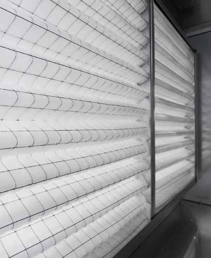
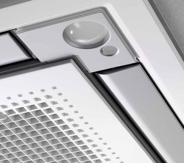
156 Options & accessories AUTO-CLEANING PANEL FILTERS INTELLIGENT SENSORS 154
157 Options & accessories Sky Air 156 Indoor units 156 Outdoor units 258 Ventilation 160 Air handling units 161 Options & Accessories 155
158 Options - Sky Air INDOOR UNITS FCAHG-G FCAG-A FFA-A FDBQ-B FDXM-F3 FBA-A FDA-A Panels Decoration panel (obligatory for cassette units, optional for others) Panel spacer for reducing required installation height BYCQ140D (standard) BYCQ140DW (white)(1) BYFQ60CW (white) BYCQ140DG9/ BYFQ60CS (silver) BYCQ140DGF9 BYFQ60B3 (standard) (auto-cleaning)(2)(4) KDBQ44B60 (only for standard panel) Centralised control Individual control systems systems Building Management System & Standard protocol interface Sealing kit for 3- or 2-directional air discharge KDBHQ55B140 (11) BDBHQ44C60 BRYQ60AW (white)(9) Sensor kit BRYQ140A BRYQ60AS (silver)(9) BRP069A81 - Online Controller BRC7EB530W for standard panel (5)(6) Infrared remote control (incl. receiver) BRC7FA532F (11) BRC7F530W BRC4C65 BRC4C65 BRC4C65 for white panel (5)(6) BRC7F530S - for silver panel (5)(6) BRC1H51W (Glossy white) / BRC1H51S (Metallic silver) / BRC1H51K (Black matte) - User-friendly wired remote controller with premium design BRC1E53A/B/C (3) (13) - Wired remote control with full-text interface and back-light BRC1D52 (13) - Standard wired remote control with weekly timer BRC2E52C (3) (13) - Simplified remote control (with operation mode selector button) BRC3E52C (3) (13) - Simplified remote control (without operation mode selector button) ARCWB - Wired remote controller DIII-net connection - for connection to centralized control standard standard standard standard standard DCC601A51 - Intelligent tablet controller DCS601C51 (13) - Intelligent touch controller DCS302C51 (13) - Central remote control DCS301B51 (13) - Unified ON/OFF control DST301B51 (13) - Schedule timer NIM03 - R Option PCB for group control DCM601A51 - Intelligent Touch Manager RTD-NET - Modbus interface for monitoring and control RTD-10 - Modbus interface for infrastructure cooling RTD-20 - Modbus interface for retail RTD-HO - Modbus interface for hotel EKMBDXA - Modbus interface KLIC-DI - KNX Interface DCM010A51 - Daikin PMS interface DMS502A51 - BACnet Interface DMS504B51 - LonWorks Interface Filters Adapter Replacement long-life filter, non-woven type KAFP551K160 KAFQ441BA60 Auto cleaning filter see deco panel BAE20A62 (25-35) BAE20A102 (50-60) Wiring adapter for external monitoring/control via dry contacts and setpoint control via Ω KRP4A53 (10)(11) KRP4A53 (10) KRP4A54 (10) KRP4A52 (10) Wiring adapter with 2 output signals (compressor/ Error, Fan output) KRP1B57 (10)(11) KRP1B57 (10) KRP1B56 (10) Wiring adapter for external central monitoring/control (controls 1 entire system) KRP2A53 (10) KRP2A51 (7)(10) KRP2A51 (8) Adapter for wiring (interlock for fresh air intake fan) KRP1B54 KRP1C64 (7) Wiring adapter with 4 output signals (compressor / Error, Fan, Aux, heater, Humidifier output) EKRP1C11 (10)(11) EKRP1B2 EKRP1B2 EKRP1B2 (7) EKRP1B2 (7) Adapter for keycard or window contact connection (in combination with BRC1H*, BRC1/2/3E* only) BRP7A53 BRP7A53 BRP7A53 BRP7A54 (10) BRP7A51 (12) BRP7A54 (12) Installation box/mounting plate for adapter PCBs (when there is no space in the switchbox, an installation box is required) KRP1H98 (11) KRP1B101/KRP1BA101 KRP1BA101 KRP1B101/KRP1BA101 KRP4A96 External wired temperature sensor KRCS01-4 KRCS01-4 KRCS01-1 KRCS01-4 KRCS01-4 KRCS01-4 K.RSS - External wireless temperature sensor Remote ON/OFF, forced OFF kit standard standard standard standard standard EKRORO3 DTA112B51 - Interface adapter for Sky Air Drain pump kit Others Multi zoning kit (for detailed model code overview refer to multizoning argue card in this catalogue) L-type piping kit (upward direction) 2 dampers (25-35) 3 dampers (25-35) 4 dampers (50) 5 dampers (60) 2 dampers (35-50) 3 dampers (35-50) 4 dampers (35-71) 5 dampers (60-140) 6 dampers (60-140) 7 dampers ( ) 8 dampers ( ) Fresh air intake kit (direct installation type) Air discharge adapter for round duct KDDQ55B KDDQ55B140-2 (11) KDDQ44XA60 KDAP25A56A (35-50) KDAP25A71A (60-71) KDAP25A140A [ ) KDAJ25K140A (1) Dirt formation is more easily visible on white insulation. It is recommended not to install this option in environments with a high concentration of dirt. (2) To be able to control option BYCQ140DG(F)9, controller BRC1H*, BRC1E* is needed. These options cannot be combined with RXYSQ*, multi or non-inverter split units 156 (3) Included languages are: A: English, German, French, Dutch, Spanish, Italian and Portuguese B: English, Bulgarian, Croatian, Czech, Hungarian, Romanian and Slovenian C: English, Greek, Polish, Russian, Albanian, Slovak and Turkish (in case of BRC2/3E52C Serbian is available instead of Albanian) For BRC2/3E52C use PC cable EKPCCAB3 in combination with the updater PC software to change to language pack B or C
159 FDQ-B ADEQ-C ABQ-C FHA-A AHQ-C FUA-A FAA-A FVA-A FNA-A KDBHP49B140 + KDBTP49B140 BRC4C65 BRC4C65 BRC7G53 BRC7CB58 BRC7EB518 BRC4C65 DTA112B51 standard standard standard standard standard KAFP501A56 (35-50) KAFP501A80 (60-71) KAFP551K160 KAFJ95L160 KAFP501A60 ( ) KRP4A51 (8) KRP4A52 (10) KRP4A53 (10) KRP4A51 (10) KRP4A52 (10) KRP4A54 KRP1B57 (10) KRP2A51 (8) KRP1B54 (8) KRP1B59 KRP1B54 (10) EKRP1B2 (7)(8) EKRP1B2A (7) KRP1B56 BRP7A54 (8) BRP7A52 (10) BRP7A53 (10) BRP7A51 (10) BRP7A52 BRP7A51 KRP4A96 KRP1D93A [box) KKSAP50A56 (35-50) KRP1BA97 KRP4A93 KRP4AA95 KRP1BA101 [mounting plate) KRCS01-1 KRCS01-4 KRCS01-4 KRCS01-4 KRCS01-4 EKRORO standard standard KDUP50Q63 (35-60) KDUP50Q160 (71-140) K-KDU572EVE Options & Accessories 4 dampers (71) 5 dampers (71-125) 6 dampers (71-125) 7 dampers ( ) 8 dampers ( ) KHFP5MA35 (35) KHFP5N63 (50-60) KHFPN5N160 (71-140) KDDQ50A140 KDAP25A71A (71) KDAP25A140A (100/125) (4) The option is intended exclusively for use in fine dust enviornments (e.g. Clothing shops). Do not use it in environments that are greasy or have high humidity. (5) Sensing function is not available (6) Individual flap control function not available (7) If installing an electrical heater, an option PCB for external electrical heater (EKRP1B2) for each indoor unit is required. These options require mounting plate KRP4A96. Electrical heaters and humidifiers are field-supplied. Do not install them inside the equipment. (8) Mounting plate KRP4A96 is required for these options. Maximum 2 option PCB s can be mounted. (9) This option cannot be used with RR and RQ models (10) Requires installation box for adapter PCB, refer to table for model code (11) This option cannot be combined with BYCQ140DG(F)9 (12) Maximum 2 optional PCBs can be mounted (13) Applicable boxes (KJB*) to mount controllers can be found in the controls option list 157
160 R-32 RZAG-MV1/MY1 RZASG-MV1/MY1 AZAS-MV1/MY1 Refrigerant branch piping for twin KHRQ22M20TA KHRQ22M20TA for triple KHRQ127H ( ) KHRQ127H ( ) for double twin KHRQ22M20TA (3x) ( ) KHRQ22M20TA (3x) ( ) Demand adapter kit SB.KRP58M52 SB.KRP58M52 SB.KRP58M52 Bottom plate heater EKBH140L7 Refrigerant branch For twin For triple Drain plug For double twin R-410A RZQG-L9V1 RZQG-L(8)Y1 RZQSG-L3V1 RZQSG-L(8)Y1 AZQS-B8V1 AZQS-BY1 RZQ-C KHRQ22M20TA KHRQ127H ( ) KHRQ22M20TA (x3) ( ) KHRQ22M20TA (KHRQ58T) (1) KHRQ127H ( ) (KHRQ58H) (1) KHRQ22M20TA (x3) ( ) (KHRQ58T) (1) Demand adapter kit SB.KRP58M51 KRP58M51 KHRQ22M20TA KHRQ127H ( ) KHRQ22M20TA (x3) ( ) KRP58M51 (71) SB.KRP58M51 ( ) KHRQ22M20TA (KHRQ58T) (1) KHRQ127H ( ) (KHRQ58H) (1) KHRQ22M20TA (x3) ( ) (KHRQ58T) (1) KRP58M51 KRP58M51 (71) SB.KRP58M51 ( ) KRP58M51 KWC26B280 KHRQ22M20TA KHRQ250H7 KHRQ22M20TA (x3) KRP58M51 Bottom plate heater EKBPH140L7 EKBPH140L7 (2) (1) For RZQG-L(8)Y1 in combination with FCAG35-71* or FCAHG-* use refrigerant branch piping between brackets (2) For combination of RZQG71 and EKBPH140L7 the demand adapter kit is needed in order to connect the bottom plate heater 158

161 159 Options & Accessories
162 Options & accessories Ventilation VAM 150FC VAM 250FC VAM 350FC VAM 500FC VAM 650FC VAM 800FC VAM 1000FC VAM 1500FC VAM 2000FC Dust filters EN779 Medium M6 - - EKAFV50F6 EKAFV50F6 EKAFV80F6 EKAFV80F6 EKAFV100F6 EKAFV100F6 x2 EKAFV100F6 x2 EN779 Fine F7 - - EKAFV50F7 EKAFV50F7 EKAFV80F7 EKAFV80F7 EKAFV100F7 EKAFV100F7 x2 EKAFV100F7 x2 EN779 Fine F8 - - EKAFV50F8 EKAFV50F8 EKAFV80F8 EKAFV80F8 EKAFV100F8 EKAFV100F8 x2 EKAFV100F8 x2 Silencer Model name KDDM24B50 KDDM24B100 KDDM24B100 KDDM24B100 KDDM24B100 x2 KDDM24B100 x2 Nominal pipe Diameter (mm) CO 2 sensor - - BRYMA65 BRYMA65 BRYMA65 BRYMA100 BRYMA100 BRYMA200 BRYMA200 VH electrical heater for VAM VH1B VH2B VH2B VH3B VH3B VH4B / VH4/AB VH4B / VH4/AB VH5B VH5B Individual control systems VAM-FC EKEQFCBA 2 EKEQDCB 2 EKEQMCBA 2 Wired remote control BRC1E52A/B / BRC1D52 BRC1E52A/B / BRC1D52 BRC1E52A/B / BRC1D52 1 BRC1E52A/B / BRC1D52 1 VAM wired remote control BRC301B Centralised control systems VAM-FC EKEQFCBA 2 EKEQDCB 2 EKEQMCBA 2 Centralised remote control DCS302C Unified ON/OFF control DCS301B Schedule timer DST301B DCC601A51 DCC601A Intelligent Touch Manager DCM601A51 DCM601A51 DCM601A51 DCM601A51 Modbus DIII adapter EKMBDXA7V1 EKMBDXA7V1 EKMBDXA7V1 EKMBDXA7V1 BACnet interface DMS502A LonWorks interface DMS504B Others VAM FC VAM FC EKEQFCBA 2 EKEQDCB 2 EKEQMCBA 2 Wiring adapter for electrical appendices (note 7) KRP2A51 KRP2A51 (note 3) Adapter PCB for humidifier KRP50-2 KRP1C4 (note 4/6) Adapter PCB for 3rd party heater BRP4A50 BRP4A50A (note 4/5) Remote sensor KRCS Notes (1) Cool/heat selector required for operation (2) Unless otherwise specified DIII-net devices cannot be connected to the system (3) Installation box KRP1BA101 needed. (4) Fixing plate EKMPVAM additionally needed for VAM FB. (5) 3rd party heater and 3rd party humidifier cannot be combined (6) Installation box KRP50-2A90 needed. (7) For external control and monitoring (ON/OFF control, operation signal, error indication) VH electrical heater for VAM Supply voltage 220/250V ac 50/60 Hz. +/-10% Output current (maximum) 19A at 40 C (ambient) Temperature sensor 5k ohms at 25 C (table 502 1T) Temperature control range 0 to 40 C / (0-10V 0-100%) Run on timer Adjustable from 1 to 2 minutes (factory set at 1.5 minutes) Control fuse 20 X5 mm 250 m A LED indicators Mounting holes Maximum ambient adjacent to terminal box Auto high temp. cutout Man. reset high temp. cutout Run relay BMS setpoint input Power ON - Yellow Heater ON - Red (solid or flashing, indicating pulsed control) Airflow fault - Red 98mm X 181mm centres 5 mm ø holes 35 C (during operation) 100 C Pre-set 125 C Pre-set 1A 120V AC or 1A 24V DC 0-10VDC Vh electrical heater for vam vh1b VH2B VH3B VH4B VH4/AB VH5B Capacity kw Duct diameter mm Connectable VAM VAM150FC VAM250FC VAM500FC VAM800FC VAM800FC VAM1500FC - VAM350FC VAM650FC VAM1000FC VAM1000FC VAM2000FC 160
163 Options & accessories D-AHU Professional Construction type SP 65 SP 45 FP 50 FP 25 Profile Aluminium standard standard standard standard Anodized aluminium option option option option Aluminium with thermal break option option option option Anodized aluminium with thermal break option option option option Corner Glass fibre reinforced nylon standard standard standard standard Panel insulation External sheet material Internal sheet material Base frame Polyurethane foam density 45 kg/m 3 thermal conductivity W/m*K fire reaction class 1 standard standard standard standard Mineral wool density 90 kg/m 3 thermal conductivity W/m*K (referred to 20 C) fire reaction class 0 option option option option Grey Plastisol covered galvanized steel standard standard standard standard Pre-coated galvanized steel option option option option Galvanized steel option option option option Aluminium option option option option AISI 304 stainless steel option option option option Galvanized steel standard standard standard standard Pre-coated galvanized steel option option option option Grey Plastisol covered galvanized steel option option option option Aluminium option option option option AISI 304 stainless steel option option option option Aluminium standard standard standard standard (from size 1 to size 17) (from size 1 to size 17) (from size 1 to size 17) (from size 1 to size 17) Galvanized steel standard standard standard standard (from size 18 to size 27) (from size 18 to size 27) (from size 18 to size 27) (from size 18 to size 27) Handle Glass fibre reinforced nylon standard standard standard standard Compression type standard standard standard standard Type Hinge function type (possibility to remove door) option option option option D-AHU Easy Construction type DS 50 DS 25 Profile Aluminium Standard Standard Corner Glass fibre reinforced nylon Standard Standard Panel insulation Polyurethane foam thermal conductivity W/m*K Standard (density 45 kg/m 3 ) standard (density 47 kg/m 3 ) External sheet material Pre-coated galvanized steel (RAL 9002) Standard Standard Internal sheet material Galvanized steel Standard Standard Base frame Aluminium Standard Standard Handle Glass fibre reinforced nylon Standard Standard Type Compression type Standard Standard Options & Accessories 161


164 We re here to help you! Online and offline General catalogue
165 Tools and platforms Literature overview 164 Supporting tools, software and apps 166 Tools & Platforms 163
166 VRV IV heat recovery, heat pump, replacement and water cooled The quick and quality way of upgrading R-22 and R-407C systems Get ahead of competition Easy to use: all main functions directly accessible Set up to 3 independent schedules, so the user can easily change the schedule himself throughout the Easy commissioning: intuitive interface for advanced year (e.g. summer, winter, mid-season) menu settings Real time clock with auto update to daylight saving Optimise your air conditioning system by activating a time series of energy saving functions (temperature range limit, setback function, off timer, ) Supports multiple languages Keep track of your energy consumption with the Possibility to individually restrict menu functions kwh indication showing an indicative electricity consumption When a power failure occurs all settings remain stored up to 48 hours thanks to the built-in backup power R-32 IS AN INDUSTRY REVOLUTION. VRV IV heat pumps for indoor installation Compact VRV IV heat pumps for residential and light commercial applications RELIABLE, CONTINUOUS OPERATION For server rooms, telecom shelters, laboratories, IT applications Minimum running costs, maximum flexibility. Fast installation, top reliability, perfect comfort. Introducing the new Sky Air A-series with ultra-efficient Bluevolution R-32 technology Integration of Daikin portfolio in BMS system via Modbus Indoor unit control Retail applications via 0~10 volt, dry contact Hotel applications or resistance contact IT applications Heating interlock Alarm signal Split, Sky Air, VRV, Chillers, Refrigeration, Daikin Altherma Commercial market - literature overview for professional network Solution guides: Reference books: Product profiles: VRV IV 360 efficiency VRV IV range Detailed VRV IV standards and technologies benefits. Main features and specs of VRV IV product range 206 i Keep looking you ll never find me Keep looking you ll never find me VRV IV i-series Main benefits, application examples and specs of VRV IV i-series product range 207 VRV IV S-series Main benefits, application examples and specs of VRV IV S-series product range Our mission Achieve the lowest environmental impact Sky Air A-series Main benefits and specs 116 Expected Water-to-air heat pump Detailed info on VRV IV W-series, application examples, technical system design background Focus topics: Replacement technology for installers Replacement Technology Clear installer benefits of VRV replacement technology Infrastructure cooling solution Infrastructure cooling Clear installer benefits why to choose Daikin for infrastructure cooling Product flyers: User friendly remote control with contemporary design BRC1E52A/B Wired Remote Control Detailed info on BRC1E52A/B remote control Modbus Interface RTD RTD modbus interface Detailed info on RTD controls and applications Product catalogues: Sky Air Product catalogue 2017 for professionals Sky Air Catalogue Detailed technical information & benefits on Sky Air/Ventilation/ Biddle Air Curtain/Control systems/ahu VRV Product catalogue 2017 for professionals VRV Catalogue Detailed technical information & benefits of the VRV total solution Ventilation Catalogue Detailed info on Ventilation products BE PART OF IT. NEW webbased Xpress selection software
167 365-days climate comfort for every business Mini Building Management System Avoid loss of business and replace your air conditioning system now! Home leave operation Powerful mode Multi tenant (FXNQ-A) SPLIT, SKY AIR, VRV, CHILLERS FNQ-A, FXNQ-A Designed to be concealed in walls Ideal for installation in offices, hotels and residential Discretely concealed in the wall, leaving only the applications suction and discharge grilles visible Its low height enables the unit to fit perfectly beneath Requires very little installation space as the depth is a window only 200mm High ESP allows flexible installation Your business at your fingertips Home leave operation Powerful mode Optimum comfort guaranteed no matter the length of ductwork or type of grilles Top efficiency in the market Automatic air flow adjustment function measures the air volume and static pressure and adjusts it towards the nominal air flow, whatever the length of duct, making installation easier and guaranteeing comfort. Moreover, the ESP can be changed via the wired remote control to optimize the supply air volume Slimmest unit in class, only 245mm Multi tenant (FXSQ) Discretely concealed in the ceiling: only the suction and discharge grilles are visible Low sound level Tablet FBQ-D, FXSQ-A Medium external static pressure up to 150Pa facilitates using flexible ducts of varying lengths Reduced energy consumption thanks to specially developed DC fan motor Flexible installation, as the air suction direction can be altered from rear to bottom suction Standard built-in drain pump increases flexibility and installation speed No optional adapter needed for DIII-connection, link your unit into the wider building management system Sustainable design with Daikin HVAC-R systems Heating - air conditioning - hot water - ventilation - refrigeration - control Tools and platforms for your customers Commercial solutions for small to large applications Commercial Solutions Daikin offers solutions for commercial applications 100 Green building solutions Green Buiding Solutions Clear building owner/investor benefits why to choose Daikin for a green building, with emphasis on BREEAM 216 Reference catalogue Daikin commercial and industrial references 213 Hotel solutions for hotel owners Hotel Solutions Clear building owner/investor benefits why to choose Daikin for a hotel 218 Control systems Intelligent Touch Manager Intelligent Touch Manager Detailed benefits of Intelligent Touch Manager intelligent Tablet Controller with cloud connection DCC601A51 Detailed benefits of DCC601A51 and Daikin Cloud Service The phase-out period for R-22 is over. Act now! Replacement technology Clear building owner/investor benefits of replacement technology 215 Concealed floor standing unit Sky Air product leaflets Single page leaflet with the main benefits and technical specifications of each individual Sky Air unit. Ideal for quotations Concealed ceiling unit with medium ESP VRV product leaflets Single page leaflet with the main benefits and technical specifications of each individual VRV unit. Ideal for quotations Technical documentation: All latest Daikin catalogues are available in a convenient library on the internet: Tools & Platforms 165
.")


168 Tools and platforms Supporting tools, software and apps support-and-manuals/ software-downloads Software Ventilation Xpress Selection tool for ventilation devices (VAM, VKM). The selection is based on given supply/extract airflows (including fresh up and given ESP of supply/extract ducting: Determines size of electrical heaters Visualisation of psychrometric chart Visualisation of selected configuration Required field settings mentioned in the report Webbased ASTRA selection for air handling units NEW A powerful tool to select the right Air Handling Units for your needs. 3D interface quick selection procedures new print-out possibilities and report shapes WAGO selection tool NEW The WAGO Selection Tool is specifically designed to select the optimal WAGO I/O system for your needs. Easy selection of WAGO materials Material list creation Time saving Includes wiring schemes Contains commissioning/preset data for Plugins and third-party software tools Building Information Modelling (BIM) support BIM improves efficiency of design and build phase Daikin is among the first to supply a full library of BIM objects for its VRV products com/en/ product/?freetext=daikin Energy simulation and design aid tools Psychrometrics diagram NEW The Psychrometrics Diagram Viewer demonstrates the changing properties of moist air. With this tool, users can choose two points with specific conditions, plot them on the diagram and select actions to change the conditions, i.e. heat, cool and mix air. 166


169 Service tools Error code app Quickly know the meaning of fault codes, for each product family and the potential cause D-Checker D-checker is a software application used to record and monitor operation data of Daikin applied, split, Multi-split, Sky-air units, Daikin Altherma LT, ground source heat pump, Hybrid, ZEAS, Conveni-pack & R410A Booster unit Bluetooth adaptor NEW Monitoring of Split, Sky Air and VRV data via any bluetooth device No need to access the outdoor unit Connects with D-Checker software (for laptops) Connects with monitoring app (for tablets or smartphones) Diagnosis of the Bluetooth system possible: Computer with Bluetooth Online support Internet NEW Business portal Experience our new extranet that thinks with you at my.daikin.eu Find information in seconds via a powerful search Customise the options so you see only info relevant for you Access via mobile device or desktop Find our solution for different applications: Hotel Home Supermarket Store & shop Office Restaurant Bank Sport & Leisure Technical Industry my.daikin.eu AT CUSTOMERS ON THE ROAD Get more commercial details on our flagship products via our dedicated minisites See our references AT THE OFFICE HOTEL PORTA FIRA Tools & Platforms 167

170 Europe s new energy label Labelling to encourage intelligent choices To enable consumers to compare and make purchasing decisions based on uniform labelling criteria, Europe has introduced energy labels. The previous European energy label for air conditioners, introduced in 1992, did its job for the time. In 2013, Europe introduced a seasonal energy label. This label allows end users to make even more informed choices, since seasonal efficiency reflects air conditioner efficiency over an entire season. The energy label includes multiple classifications from A+++ to D, reflected in colour shadings ranging from dark green (most energy efficient) to red (least efficient). Information on the label not only includes the seasonal efficiency ratings for heating (SCOP) and cooling (SEER), but also annual energy consumption and noise levels. The label more in detail Name of manufacturer and product SEER: seasonal efficiency values for cooling Classifications from A+++ (most energy efficient) to D (least energy efficient Combination of indoor and outdoor unit SCOP: seasonal efficiency values for heating Classifications from A+++ (most energy efficient) to D (least energy efficient) Design load for cooling Seasonal efficiency ratings for cooling (SEER) Annual energy consumption during a cooling season, including auxiliary modes Design load for heating Seasonal efficiency ratings for heating (SCOP) Annual energy consumption during a heating season, including auxiliary modes Sound power value for indoor unit Sound power value for outdoor unit To take the broad range of conditions into account, 3 climate zones are used: cold, average and warm blue = colder climate (optional) green = average climate (compulsory) orange = warmer climate (optional) 168
171 Measuring conditions Power supply Conversion table refrigerant piping T1 = 3~, 220V, 50Hz V1 = 1~, V, 50Hz VE = 1~, V/220V, 50Hz/60Hz* V3 = 1~, 230V, 50Hz VM = 1~, 220~240V/220~230V, 50Hz/60Hz W1 = 3N~, 400V, 50Hz Y1 = 3~, 400V, 50Hz * For VE power supply only 1~, V, 50Hz data is displayed in this catalogue. inch mm 1 /4 6.4 mm 3 /8 9.5 mm 1 / mm 5 / mm 3 / mm 7 / mm 1 1 / mm 1 3 / mm 1 5 / mm 1 3 / mm mm 2 1 /8 54 mm 2 5 / mm F-gas regulation For fully/partially charged equipment: contains fluorinated greenhouse gases. Actual refrigerant charge depends on the final unit construction, details can be found on the unit labels. For non pre-charged equipment (Chillers: split chiller (SEHVX/SERHQ), condensing units and condenserless chillers + refrigeration (LCBKQ-AV1, JEHCCU/JEHSCU and ICU): Its functioning relies on fluorinated greenhouse gases. Measuring conditions Air conditioning 1) Nominal cooling capacities are based on: Indoor temperature Outdoor temperature Refrigerant piping length Level difference 2) Nominal heating capacities are based on: Indoor temperature Outdoor temperature Refrigerant piping length Level difference 27 CDB/19 CWB 35 CDB 7.5m - 8/5m VRV 0m 20 CDB 7 CDB/6 CWB 7.5m - 8/5m VRV 0m The sound pressure level is measured via a microphone at a certain distance from the unit. It is a relative value, depending on the distance and acoustic environment (for measuring conditions: please refer to the technical databooks). The sound power level is an absolute value indicating the power which a sound source generates. For more detailed information please consult our technical databooks. Tools & Platforms 169

172 170
173 Technical drawings Indoor units 172 Outdoor units 202 Biddle air curtains 255 Technical Drawings 171

174 Technical drawings Indoor units FCAG-A / FCAHG-G 173 FFA-A 175 FDXM-F3 177 FBA-A 180 FDA-A 185 FDQ-B 188 ABQ-C 190 FAA-A 192 FHA-A 193 AHQ-C 196 FUA-A 197 FVA-A 198 FNA-A
175 VIEW ALL FCAG-A TECHNICAL DRAWINGS ON MY.DAIKIN.EU Detailed technical drawings FCAG-A / FCAHG-G WITH AUTO-CLEANING PANEL with auto-cleaning panel 300 or less See note (suspension position) (ceiling opening see note 3) Drain side NOTE (See note 3) 710 (suspension position) (ceiling opening, see note 3) (See note 3) 2500 or more (installation space) See note 6 1. Location of the nameplates - Unit body: on the control box cover - Decoration panel: on the panel frame at the piping side under the corner cover 2. When installing an optional accessory, refer to the installation drawings. - For fresh air intake kit an inspection part is necessary 3. Make sure the spacing between the ceiling and the cassette is no more than 35mm. Max ceiling opening: 910mm 4. When the conditions exceed 30 C and RH 80% in the ceiling or fresh air is inducted into the ceiling, an additional insulation is required (polyethylene foam, thickness 10mm or more) 5. In case of using a sensor kit, this position will be a sensor, refer to the drawing of the sensor kit for more detail 6. In case of using a infrared control, this position will be a receiver, refer to the drawing of the infrared control for more detail Adjustable (0-675) Hanging bolt 4 x M8 - M10 VIEW A Piping side DETAIL B 2 PLACES OPPOSITE SIDE 200mm or more 1500mm or more 200mm or more 1500mm or more DETAIL C 2 PLACES OPPOSITE SIDE 1500mm or more 1500mm or more REQUIRED SPACE In case a discharge opening is closed with the sealing member option, the distance of 1500mm can be reduced to 500mm on the closed side. External surface Ventilator light 1500 or more 2000 or more 4000 or more Other unit Item Name 1 Liquid pipe connection 2 Gas pipe connection 3 Drain pipe connection 4 Power supply entry hole 5 Transmission wiring entry hole 6 Air discharge opening 7 Air suction grille 8 Corner decoration cover 9 Drain hose 10 Knock out hole Model FCQG35-71FVEB, FXFQ20-63AVEB 2D090245A FCAG-A / FCAHG-G WITH STANDARD PANEL with standard panel 300 or less See note 5 Drain side NOTE (See note 3) 710 (suspension position) (ceiling opening, see note 3) 780 (suspension position) (ceiling opening see note 3) (See note 3) 2500 or more (installation space) See note 6 Adjustable (0-675) Hanging bolt 4 x M8 - M10 1. Location of the nameplates - Unit body: on the control box cover - Decoration panel: on the panel frame at the piping side under the corner cover 2. When installing an optional accessory, refer to the installation drawings. - For fresh air intake kit an inspection part is necessary 3. Make sure the spacing between the ceiling and the cassette is no more than 35mm. Max ceiling opening: 910mm 4. When the conditions exceed 30 C and RH 80% in the ceiling or fresh air is inducted into the ceiling, an additional insulation is required (polyethylene foam, thickness 10mm or more) 5. In case of using a sensor kit, this position will be a sensor, refer to the drawing of the sensor kit for more detail 6. In case of using a infrared control, this position will be a receiver, refer to the drawing of the infrared control for more detail VIEW A Piping side DETAIL B 2 PLACES OPPOSITE SIDE 200mm or more 1500mm or more 200mm or more 1500mm or more REQUIRED SPACE In case a discharge opening is closed with the sealing member option, the distance of 1500mm can be reduced to 500mm on the closed side. External surface Ventilator Other unit light 1500 or more 2000 or more 4000 or more Item Name 1 Liquid pipe connection 2 Gas pipe connection 3 Drain pipe connection 4 Power supply entry hole 5 Transmission wiring entry hole 6 Air discharge opening 7 Air suction grille 8 Corner decoration cover 9 Drain hose 10 Knock out hole Model DETAIL C 2 PLACES OPPOSITE SIDE 1500mm or more 256 FCQG FVEB, FXFQ80-100AVEB 298 FCQHG71-140FVEB, FXFQ125AVEB 1500mm or more 3D077130E Technical Drawings 173
176 Detailed technical drawings VIEW ALL FCAG-A TECHNICAL DRAWINGS ON MY.DAIKIN.EU FCAG-A FCAG-A/ FCAHG-G Duct Left side Piping side See note Drain side See note 3. Static pressure in chamber [Pa] Duct Right side View A Air flow rate [m³/min] Service access panel 450 x 450 mm or more See note 1. (1000) AA Notes Suction chamber Decoration panel A 455 Ceiling opening 725 FCAG-A/ FCAHG-G Inlet T-joint Field supply 1. When installing a fresh air intake kit, provide a service access panel. 2. Field construction 3. This corner discharge outlet needs to be closed. 4. When installing a duct fan, use a wiring adapter to link the duct fan to the fan of the indoor unit. 5. The intake air flow rate is recommended to be 20% of the air flow rate at high fan speed. If the intake air flow rate is too large, the operating sound may increase, and the detection of the indoor unit suction temperature may be affected. 6. This indicates the distance between the T-joint inlet and the indoor unit inlet when the T-tube is connected. Sensor kit Sensor kit Installation methods Drain side FCAG-A Decoration panel 3D Piping side CAG-A/ FCAHG-G Sensor kit Decoration panel Sensor kit Installation methods BRYQ140A7 BYCQ140D7W1(W) Sensor kit Installation methods Sensor kit Drain side Sensor kit Drain side Decoration panel Piping side Decoration panel Piping side Sensor kit Decoration panel BRYQ140A7 BYCQ140D7W1(W) Sensor kit Installation methods Sensor kit Decoration panel BRYQ140A7 BYCQ140D7GW9/BYCQ140D7GFW9 Sensor kit Drain side 4D Decoration panel Piping side 174
177 VIEW ALL FFA-A TECHNICAL DRAWINGS ON MY.DAIKIN.EU Detailed technical drawings FFA25-35A - FULLY FLAT PANEL FFA25-35A DECORATION PANEL 620 BYFQ60C2W1W FRESH WHITE N9.5 BYFQ60C2W1S DAIKIN SILVER 585~ 595 (CELING OPENING SPACE) 300 OR LESS 533 (SUSPENSION POSITION) PIPE CONNECTION SIDE Service Access Panel 450 x 450mm ore more DRAIN CONNECTION SIDE 5 A ARROW VIEW NOTE) B 533 (SUSPENSION POSITION) 585~ 595 (CELING OPENING SPACE) 1500mm OR MORE M4 HOLE Ø100 B ARROW VIEW REQUIRED SPACE 1500mm OR MORE OUTDOOR AIR INTAKE (DIRECT CONNECTION) 1500mm OR MORE C ARROW VIEW 850 ADJUSTABLE(0~630) mm OR MORE WHEN THE DISCHARGE GRILL IS CLOSEOUT, THE REQUIRED SPACE IS 200mm OR MORE. 260 C (190) 300 OR MORE 8 SUSPENSION BOLT 4-M8~M OR LESS 10 OR LESS NOTE)4. NOTE) 1. STICKING LOCATION FOR MANUFACTURE'S LABEL MANUFACTURE'S LABEL FOR INDOOR UNIT:ON THE BELL MOUTH INSIDE SUCTION GRILLE MANUFACTURE'S LABEL FOR DECORATION PANEL :ON THE INNER FRAME INSIDE SUCTION GRILLE 2. IN CASE OF USING WIRELESS REMOTE CONTROLLER,THIS POSITION WILL BE A SIGNAL RECEIVER. REFER TO THE DRAWING OF WIRELESS REMOTE CONTROLLER IN DETAIL. 3. WHEN THE TEMPERATURE AND HUMIDITY IN THE CEILING EXCEED 30 AND RH 80% OR THE FRESH AIR IS INDUCTED INTO THE CEILING OR THE UNIT CONTINUES 24 HOUR OPERATION,AN ADDITIONAL ITEM PART NAME REMARK φ6.4(frare ITEM 5 PART NAME REMOTE CONTROL CODE 1 LIQUID PIPE CONNECTION INSULATION (THICKNESS 10mm OR MORE OF GLASSWOOL OR POLYETHYLENE FORM) IS REQUIRED. CONNECTION) AND CONTROL WIRING CONNECTION 4. THOUGH THE INSTALLATION IS ACCEPTABLE UP TO MAXIMUM OF 595mm SQUARE CEILING OPENING, 2 GAS PIPE CONNECTION φ9.5(frare CONNECTION) 6 AIR DISCHARGE GRILL KEEP THE CLEARANCE OF 10mm OR LESS BETWEEN THE MAIN UNIT AND THE CEILING OPENING SO THAT 3 DRAIN PIPE CONNECTION VP20(O.D.φ26) 7 SUCTION GRILL THE PANEL OVERLAP ALLOWANCE CAN BE ENSURED. 4 POWER SUPPLY CONNECTION 8 DRAIN HOSE(ACCESSORY) A 1500 OR MORE (REQUIRED SPACE) FROM THE FLOOR SIDE 2500 OR MORE FOR HEIGHT INSTALLATION REMARK I.D.φ25(OUTLET) 3D FFA25-35A - STANDARD PANEL FFA25-35A Decoration panel 700 Note ) 2. BYFQ60B2W1 WHITE Ral 9010 BYFQ60B3W1 WHITE Ral or less Ceiling opening 585~ Suspension position Piping side Service access panel 450 x 450mm or more Drain side B Suspension position 533 Ceiling opening ~ 150 Ø M4 Hole Outdoor air intake (direct connection) View B ARROW Required space 1500mm or more 5 View A ARROW mm or more 1500mm or more 1500mm or more View C ARROW (0~645) 850 Adjustable When closing the air outlet, the required space is 200mm or more C (180) 295 or more Suspension bolt 4-M8~M10 Note ) 1. Location of nameplate The indoor unit nameplate is located on the bell mouth inside the suction grille. The decoration panel nameplate is located on the inner frame inside the suction grille or less 45 or less Note ) A 1500 or more Required space 2500 or more To floor Ceiling height 2. When installing a wireless controller, there will be a receiver on this location. For details, see the drawing of the wireless controller. 3. If any of the following conditions are met, additional insulation (glass wool or polyethylene foam, thickness 10mm) is required: Ambient conditions in the ceiling 30 C and 80% relative humidity. Fresh air is inducted into the ceiling. The unit operates continuously. 4. Though the installation is acceptable up to maximum 660mm square ceiling opening, keep the clearance of 45mm or less between the indoor unit and the ceiling opening, so that the panel overlap allowance can be ensured. Item Part name Remark φ6.4 1 Liquid pipe connection _ Flare connection 2 Gas pipe connection φ9.5 Flare connection 3 Drain pipe connection VP20(O.D φ26 ) 4 Power supply Item Remark Remote control wiring 5 intake 6 Air discharge grille 7 Air suction grille 8 Drain hose Accessory I.D.φ25 Outlet 3D082434C Technical Drawings 175
178 Detailed technical drawings VIEW ALL FFA-A TECHNICAL DRAWINGS ON MY.DAIKIN.EU FFA50-60A - FULLY FLAT PANEL FFA50-60A DECORATION PANEL BYFQ60C2W1W FRESH WHITE N9.5 BYFQ60C2W1S DAIKIN SILVER ~ 595 (CELING OPENING SPACE) 300 OR LESS 533 (SUSPENSION POSITION) PIPE CONNECTION SIDE Service Access Panel 450 x 450mm ore more DRAIN CONNECTION SIDE 5 A ARROW VIEW NOTE) B 533 (SUSPENSION POSITION) 585~ 595 (CELING OPENING SPACE) 1500mm OR MORE M4 HOLE Ø 100 B ARROW VIEW REQUIRED SPACE 1500mm OR MORE OUTDOOR AIR INTAKE (DIRECT CONNECTION) 1500mm OR MORE C ARROW VIEW 850 ADJUSTABLE(0~630) mm OR MORE WHEN THE DISCHARGE GRILL IS CLOSEOUT, THE REQUIRED SPACE IS 200mm OR MORE. 260 C OR MORE 8 46 SUSPENSION BOLT 4-M8~M OR LESS 10 OR LESS NOTE)4. NOTE) 1.STICKING LOCATION FOR MANUFACTURE'S LABEL MANUFACTURE'S LABEL FOR INDOOR UNIT:ON THEBELL MOUTH INSIDE SUCTION GRILLE MANUFACTURE'S LABEL FOR DECORATION PANEL :ON THE INNER FRAME INSIDE SUCTION GRILLE 2.IN CASE OF USING WIRELESS REMOTE CONTROLLER,THIS POSITION WILL BE A SIGNAL RECEIVER. REFER TO THE DRAWING OF WIRELESS REMOTE CONTROLLER IN DETAIL. ITEM PART NAME REMARK ITEM PART NAME 3.WHEN THE TEMPERATURE AND HUMIDITY IN THE CEILING EXCEED 30 AND RH 80% OR THE FRESH AIR φ6.4(frare REMOTE CONTROL CODE IS INDUCTED INTO THE CEILING OR THE UNIT CONTINUES 24 HOUR OPERATION,AN ADDITIONAL 1 LIQUID PIPE CONNECTION CONNECTION) 5 AND CONTROL WIRING INSULATION (THICKNESS 10mm OR MORE OF GLASSWOOL OR POLYETHYLENE FORM) IS REQUIRED. φ12.7(frare CONNECTION 4.THOUGH THE INSTALLATION IS ACCEPTABLE UP TO MAXIMUM OF 595mm SQUARE CEILING OPENING, CONNECTION) 6 AIR DISCHARGE GRILL 4 GAS PIPE CONNECTION KEEP THE CLEARANCE OF 10mm OR LESS BETWEEN THE MAIN UNIT AND THE CEILING OPENING SO THAT 3 DRAIN PIPE CONNECTION VP20(O.D.φ26) 7 SUCTION GRILL THE PANEL OVERLAP ALLOWANCE CAN BE ENSURED. 4 POWER SUPPLY CONNECTION 8 DRAIN HOSE(ACCESSORY) FFA50-60A - STANDARD PANEL FFA50-60A A 1500 OR MORE (REQUIRED SPACE) FROM THE FLOOR SIDE 2500 OR MORE FOR HEIGHT INSTALLATION REMARK I.D.φ25(OUTLET) 3D Decoration panel 700 Note ) 2. BYFQ60B2W1 WHITE Ral 9010 BYFQ60B3W1 WHITE Ral or less 585~ 660 Ceiling opening 533 Suspension position Piping side Service access panel 450 x 450mm or more Drain side B Suspension position 533 Ceiling opening ~ M4Hole Ø 100 View B ARROW Required space 1500mm or more Outdoor air intake (direct connection) 1500mm or more View C ARROW View A ARROW (0~645) Adjustable mm or more 1500mm or more When closing the air outlet, the required space is 200mm or more C (180) 295 or more 172 Suspension position M8~M10 Note ) 1. Location of nameplate The indoor unit nameplate is located on the bell mouth inside the suction grille. The decoration panel nameplate is located on the inner frame inside the suction grille. 2. When installing a wireless controller, there will be a receiver on this location. For details, see the drawing of the wireless controller. 3. If any of the following conditions are met, additional insulation (glass wool or polyethylene foam,thickness 10mm) is required: Ambient conditions in the ceiling 30 C and 80% relative humidity. Fresh air is inducted into the ceiling. The unit operates continuously. 4. Though the installation is acceptable up to maximum 660mm square ceiling opening, keep the clearance of 45mm or less bet ween the indoor unit and the ceiling opening, so that the panel overlap allowance can be ensured or less 45 or less Note ) A 1500 or more Required space 2500 or more To floor Ceiling height Item Part name Remark Item Part name Remark φ6.4 1 Liquid pipe connection Flare connection 5 2 φ12.7 Gas pipe connection Flare connection 6 Air discharge grille 3 Drain pipe connection VP20(O.D. φ 26) 7 Air suction grille 4 Power supply 8 Drain hose Accessory I.D.φ25 Outlet 3D082161C 176
179 VIEW ALL FDXM-F TECHNICAL DRAWINGS ON MY.DAIKIN.EU Detailed technical drawings FDXM25-35F3 FDXM25-35F OR M ORE 620 (SERVICE SPACE) (SUSPENSION BOLT PI TCH) 20 O R M O R E 16x 1/4.7 HOLE 5x P100= (SUSPENSION BOLT PITCH) 20 O R M O R E 400 O R MO RE (IN CASE OF BOTTOM SUCTION) 240 OR MORE A CEILING SERVICE SPACE VIEW A INSPECTION DOOR (CEILING OPENING) SUSPENSION BOLT 4x M8 ~ M x P150= x M5 HOLES x P100= x M4 HOLES IN CASE OF BACK SUCTION NOTES: ITEM NAME 1 LIQUID PIPE CONNECTION 2 GAS PIPE CONNECTION DESCRIPTION 1/6,4 FLARE CONNECTION 1/9,5 FLARE CONNECTION 1. IN CASE OF BACK SUCTION, MOUNT CHAMBER COVER TO BOTTOM SIDE OF THE UNIT. IN CASE OF BOTTOM SUCTION, MOUNT CHAMBER COVER TO BACK SIDE OF THE UNIT. 2. LOCATION OF UNIT NAME PLATE: CONTROL BOX COVER. 3. MOUNT THE AIR FILTER AT THE SUCTION SIDE. (USE AN AIR FILTER WHOSE DUST COLLECTING EFFICIENCY IS AT LEAST 50% IN A GRAVIMETRIC TECHNIQUE). IT CAN NOT BE EQUIPPED WITH AIR FILTER (ACCESSORY) WHEN CONNECTING DUCT TO SUCTION SIDE x M5 HOLES 5x P100= IN CASE OF BOTTOM S UCTION SOCKET FOR DRAIN DRAIN HOSE (ACCESSORY) CONTROL BOX TRANSMISSION WIRING POWER SUPPLY CONNECTION SUSPENSION BRACKET AIR FILTER (ACCESSORY) VP20(OD 1/26, ID 1/20) ID1/25 (OUTLET) D DXM50-60F3 FDXM50-60F OR MORE (SERVICE SPACE) (SUSPENSION BOLT PITCH) 20 OR MORE 20 O R MORE 400 OR MORE (IN CASE OF BOTTOM SUCTION) 240 O R M O RE xø 4,7 SUSPENSION 4x M8 ~ M10 BOLT 10x P100 = (SUSPENSION BOLT PITCH) 1080 A SERVICE SPACE CEILING VIEW A (CEILING INSPECTION OPENING) DOOR xØM x P150= x P100= x M IN CASE OF BACK SUCTION NOTES x P100= IN CASE OF BACK SUCTION, MOUNT CHAMBER COVER TO BOTTOM SIDE OF THE UNIT. IN CASE OF BOTTOM SUCTION, MOUNT CHAMBER COVER TO BACK SIDE OF THE UNIT. 2. LOCATION OF UNIT NAME PLATE: CONTROL BOX COVER. 3. MOUNT THE AIR FILTER AT THE SUCTION SIDE. (USE AN AIR FILTER WHOSE DUST COLLECTING EFFICIENCY IS AT LEAST 50% IN A GRAVIMETRIC TECHNIQUE). IT CAN NOT BE EQUIPPED WITH AIR FILTER (ACCESSORY) WHEN CONNECTING DUCT TO SUCTION SIDE IN CASE OF BOTTOM SUCTION 80 ITEM NAME 1 LIQUID PIPE CONNECTION 2 GAS PIPE CONNECTION 3 SOCKET FOR DRAIN 4 DRAIN HOSE (ACCESSORY) 5 CONTROL BOX 6 TRANSMISSION WIRING 7 POWER SUPPLY CONNECTION 8 SUSPENSION BRACKET 9 AIR FILTER (ACCESSORY) DESCRIPTION 1/6.4 FLARE CONNECTION 1/12.7 FLARE CONNECTION VP20 (OD 1/26, ID 1/20) ID 1/25 (OUTLET) D Technical Drawings 177
180 Detailed technical drawings VIEW ALL FDXM-F TECHNICAL DRAWINGS ON MY.DAIKIN.EU FDXM25-35F3 (mmh2 O) (mmh2 O) External static pressure [Pa] Upper limit of ESP H L 1 SL (PA) (mmh2 O) (mmh2 O) Air flow rate [m³/min] 3D081327C FDXM50F3 (mmh2 O) (mmh2 O) External static pressure [Pa] H SL L Lower limit of ESP 2 1 (mmh2 O) (PA) (mmh2 O) Air flow rate [m³/min] 3D085960C 178
181 VIEW ALL FDXM-F TECHNICAL DRAWINGS ON MY.DAIKIN.EU Detailed technical drawings FDXM60F3 (mmh2o) 7 70 (mmh2o) External static pressure [Pa] Upper limit of ESP L H Loweer limit of ESP SL 1 (mmh2o) [PA] (mmh2o) Air flow rate [m³/h] 3D081329C Technical Drawings 179
182 Detailed technical drawings FBA35A FBA35A VIEW ALL FBA-A TECHNICAL DRAWINGS ON MY.DAIKIN.EU 170 Ø 100 (Knockout hole.) Fresh air intake position Suspension bolt x65= KJ KC KE KH 300 or more Service space P.C.D. 4-M4 (CLASS 2) x140= Suspension position 6x65= or more Service space KK KF x145=590 KD ARROW VIEW A KA KB Suspension position ARROW VIEW A KG Ø4.7 HOLE Item KA Name Liquid pipe connection port Description Ø6.35 flared connection KB Gas pipe connection port Ø9.52 flared connection KC KD KE KF KG KH KJ KK Drain pipe connection Wiring connection Power supply connection Drain outlet Air filter Air suction side Air discharge side Nameplate VP20 (OD Ø26, ID Ø20) VP20 (OD Ø26, ID Ø20) / / / / / / Notes 1.When installing optional accessories, refer to their respective documentation. 2.The ceiling depth varies according to the documentation of the specific system. 3D094988B FBA50A FBA50A 170 Ø 100 (Knockout hole.) Fresh air intake position Suspension bolt x65= KJ KC KE KH 300 or more Service space P.C.D. 4-M4 (CLASS 2) x140= Suspension position 6x65= or more Service space KK KF x145=590 KD ARROW VIEW A KA KB Suspension position ARROW VIEW A KG Ø4.7 HOLE Item KA Name Liquid pipe connection port Description Ø6.35 flared connection Notes 1. When installing optional accessories, refer to their respective documentation. 2. The ceiling depth varies according to the documentation of the specific system. KB Gas pipe connection port Ø12.70 flared connection KC KD KE KF KG KH KJ KK Drain pipe connection Wiring connection Power supply connection Drain outlet Air filter Air suction side Air discharge side Nameplate VP20 (OD Ø26, ID Ø20) VP20 (OD Ø26, ID Ø20) / / / / / / 3D094918B 180
183 VIEW ALL FBA-A TECHNICAL DRAWINGS ON MY.DAIKIN.EU Detailed technical drawings FBA60A FBA60A 170 Ø100 (Knockout hole.) Fresh air intake position Suspension bolt x65=130 KJ KC KE KH 300 or more Service space P.C.D. 4 x M4 (CLASS 2) x146= or more Service space KK KF KD ARROW VIEW A 1038 Suspension position 11x65= x145=890 KA Suspension position ARROW VIEW A FBA71A FBA71A 170 Ø100 (Knockout hole.) Fresh air intake position Suspension bolt x65=130 KJ KC KE KH 300 or more Service space P.C.D. 4 x M4 (CLASS 2) x146= or more Service space KK KF KD ARROW VIEW A 1038 Suspension position 11x65= x145=890 KA ARROW VIEW A 630 KB KG KG Ø4.7 HOLE Item KA Name Liquid pipe connection port Description Ø6.35 flared connection KB KC KD KE KF KG KH KJ KK Gas pipe connection port Drain pipe connection Wiring connection Power supply connection Drain outlet Air filter Air suction side Air discharge side Nameplate Ø12.70 flared connection VP20 (OD Ø26, ID Ø20) VP20 (OD Ø26, ID Ø20) / / / / / / Notes 1. When installing optional accessories, refer to their respective documentation. 2. The ceiling depth varies according to the documentation of the specific system. 3D094983B Suspension position KB KG KG Ø4.7 HOLE Item Name Description KA Liquid pipe connection port Ø9.52 flared connection KB Gas pipe connection port Ø15.90 flared connection Notes 1. When installing optional accessories, refer to their respective documentation. 2. The ceiling depth varies according to the documentation of the specific system. KC KD KE KF KG KH KJ KK Drain pipe connection Wiring connection Power supply connection Drain outlet Air filter Air suction side Air discharge side Nameplate VP20 (OD Ø26, ID Ø20) VP20 (OD Ø26, ID Ø20) / / / / / / 3D094915B Technical Drawings 181
184 Detailed technical drawings VIEW ALL FBA-A TECHNICAL DRAWINGS ON MY.DAIKIN.EU FBA A FBA A 170 Ø100 (Knockout hole.) Fresh air intake position Suspension bolt x65= KJ KC KE KH 300 or more Service space P.C.D. 4 x M4 (CLASS 2) KK 7x156= KF or more Service space KD ARROW VIEW A 1438 Suspension position 16x65= X150=1200 KA Suspension position KB KG ARROW VIEW A KG xØ4.7 HOLE Item Name Description KA KB KC KD KE KF KG KH KJ KK Liquid pipe connection port Gas pipe connection port Drain pipe connection Wiring connection Power supply connection Drain outlet Air filter Air suction side Air discharge side Nameplate Ø9.52 flared connection Ø15.90 flared connection VP20 (OD Ø26, ID Ø20) / / VP20 (OD Ø26, ID Ø20) / / / / Notes 1. When installing optional accessories, refer to their respective documentation. 2. The ceiling depth varies according to the documentation of the specific system. 3D094914B FBA35-50A FBA35-50A 200 Fan characteris cs (1) 200 Fan characteris cs (3) Air flow auto adjustment H-Tap * *1 Lower limit of ESP Upper limit of ESP *1 Upper limit of ESP M-Tap *1 100 H-Tap *2 100 L-Tap *1 H-Tap 50 *2 Upper limit of ESP L-Tap *2 *3 Upper limit of ESP M-Tap *2 H-Tap *3 *2 Lower limit of ESP 50 L-Tap M-Tap 2. L-Tap *3 M-Tap *3 *3 Lower limit of ESP Lower limit of ESP Air flow rate [m³/min] Air flow rate [m³/min] Mark *1 *2 *3 ESP [Pa] MAX STD 30 Fan characteris cs (2) Field se ng with remote control 1. Upper limit of ESP by air flow auto adjustment 2. Lower limit of ESP by air flow auto adjustment Air flow rate range (H) External sta cpressure[pa] Air flow rate [m³/ m in] Notes: 1. The fan characteristics shown are in "fan only" mode. 2. ESP: External static pressure. 3D095521B 182
185 FBA60-71A FBA60-71A VIEW ALL FBA-A TECHNICAL DRAWINGS ON MY.DAIKIN.EU Detailed technical drawings 200 Fan characteris cs( 1) 200 Fan characteris cs (3) Air flow auto adjustment H-Tap * *1 Lower limit of ESP Upper limit of ESP 100 *1 Upper limit of ESP H-Tap *2 100 H-Tap L-Tap *1 M-Tap *2 *2 Lower limit of ESP *2 Upper limit of ESP 50 L-Tap *2 *3 H-Tap *3 Upper limit of ESP M-Tap *3 L-Tap *3 *3 Lower limit of ESP M-Tap L-Tap 2. Lower limit of ESP Mark ESP [Pa] 150 *1 MAX 100 *2 - *3 STD 30 Air flow rate [m³/min] Air flow rate [m³/min] 1. Upper limit of ESP by air flow auto adjustment 2. Lower limit of ESP by air flow auto adjustment Fan characteris cs(2) Field set ng with remote control Air flow rate range (H) External sta cpressure[pa] Air flow rate [m³/min] Notes: 1. Fan characteristics as shown are in "fan only" mode. 2. ESP: External static pressure. 3D095524B FBA100A FBA100A 200 Fan characteris cs (1) 200 Fan characteris cs (3) Air flow auto adjustment H-Tap * External sta c pressure [Pa] *1 Upper limit of ESP L-Tap *1 *2 Upper limit of ESP L-Tap *2 *3 Upper limit of ESP M-Tap *1 M-Tap *2 *1 Lower limit of ESP H-Tap *2 *2 Lower limit of ESP H-Tap *3 External static pressure [Pa] Upper limit of ESP L-Tap M-Tap H-Tap L-Tap *3 M-Tap *3 *3 Lower limit of ESP 0 17 Lower limit of ESP Mark *1 *2 *3 ESP [Pa] MAX STD 40 Air flow rate [m³/min] Fan characteris cs (2) Field se ng with remote control Air flow rate [m³/min] 1. Upper limit of ESP by air flow auto adjustment 2. Lower limit of ESP by air flow auto adjustment Air flow rate range (H) External static pressure [Pa] Air flow rate [m³/min] Notes: 1. Fan characteristics as shown are in "fan only" mode. 2. ESP: External static pressure. 3D095526B Technical Drawings 183
186 Detailed technical drawings FBA A VIEW ALL FBA-A TECHNICAL DRAWINGS ON MY.DAIKIN.EU 200 Fan characteris cs (1) 200 Fan characteris cs (3) Air flow auto adjustment H-Tap * Upper limit of ESP 1. External sta c pressure [Pa] *1 Upper limit of ESP L-Tap *1 *2 Upper limit of ESP L-Tap *2 M-Tap *1 M-Tap *2 H-Tap *2 *1 Lower limit of ESP *2 Lower limit of ESP H-Tap *3 External sta c pressure [Pa] M-Tap L-Tap 2. H-Tap *3 Upper limit of ESP L-Tap *3 M-Tap *3 Lower limit of ESP 0 20 *3 Lower limit of ESP Air flow rate [m³/ m i n ] Air flow rate [m³/ m i n ] Mark *1 *2 *3 ESP [Pa] MAX STD 50 Fan characteris cs (2) Field setting with remote control 1. Upper limit of ESP by air flow auto adjustment 2. Lowerl imi t o f E S P by ai r flow auto adjustment Air flow rate range (H) External sta c pressure [Pa] Air flow rate [m³/ m i n ] Notes: 1. Fan characteristics as shown are in "fan only" mode. 2. ESP: External static pressure. 3D095527B 184
187 VIEW ALL FDA-A TECHNICAL DRAWINGS ON MY.DAIKIN.EU Detailed technical drawings FDA125A FDQ125C (Knock out hole) Fresh air intake position Suspension bolt 350 or more (Service space) (On circumference) 500 or more (Service space) Detail B (Suspension position) (Ceiling opening) (Ceiling opening) 390 or more (Service space) (Suspension position) Item View A-A Name Liquid pipe connection Gas pipe connection Drain pipe connection Remote controller wiring connection Power supply connection Drain hole Air filter Air suction side Air discharge side Nameplate NOTES Description Ø 9.52 Flare connection Ø Flare connection VP25 (O.D. Ø32, I.D. Ø 25) VP25 (O.D. Ø32, I.D. Ø 25) Detail B 1 Refer to the outlook drawing of optional accessories when installing them. 2 The required ceiling depth varies according to the configuration of the specific system. 3 For maintenance of the air filter, it is neœssary to provide a service access panel. 4 Optional decoration panel: BYB5125DJW1 (light ivory white 1OY9/0.5) With decoration panel FDA125A FDQ125C or less Installation without air inlet duct Installation with air inlet duct Number Description Suspended ceiling Ceiling openinq Service access panel (optional) Air filter Air inlet duct Duct service opening NOTES 1 When installing the unit with rear suction, a service opening is necessary for the maintenance of the air filters. 2 When installing the unit with a suction duct, a service opening must be provided in the duct. Technical Drawings 185
188 Detailed technical drawings VIEW ALL FDA-A TECHNICAL DRAWINGS ON MY.DAIKIN.EU FDA-A FDQ125C Fan characteristics (1) H (max. ESP) Upper limit of external static pressure (max. ESP) Externalstatic pressure [Pa] Upper limit of external static pressure (max. ESP) L (max. ESP) L (Standard ESP) M (max. ESP) M (Standard ESP) H (Standard ESP) Lower limit of external static pressure (Standard ESP) Lower limit of external static pressure (max. ESP) Airflow [m3/min] NOTES 1. The fan characteristics shown are in "fan only" mode. 2. ESP: External Static Pressure FDA-A FDQ125C Fan characteristics (2) (Field setting with remote controller) range of available air flow rate (H) Externalstatic pressure [Pa] Airflow [m3/min] NOTES 1. The fan characteristics shown are in "fan only" mode. 2. ESP: External Static Pressure 186
189 VIEW ALL FDA-A TECHNICAL DRAWINGS ON MY.DAIKIN.EU Detailed technical drawings FDA-A FDQ125C Fan characteristics (3) (air flow auto adjustment ) Upper limit of external static presure Externalstatic pressure [Pa] L Upper limit of ESP by airflow auto adjustment M Lower limit of ESP by airflow auto adjustment H Airflow [m3/min] NOTES 1. The fan characteristics shown are in "fan only" mode. 2. ESP: External Static Pressure Technical Drawings 187
190 Detailed technical drawings VIEW ALL FDQ-B TECHNICAL DRAWINGS ON MY.DAIKIN.EU FDQ B FDYP B View A View A 1) Power supply intake 2) Drain connection fi 250 O.D. 3) Gas pipe connection FDYP200B/250B:1 1/8" O.D. OR 28,6MM FDQ200/250: 7/8" O.D. OR 22,2MM O.D. 4) Liquid pipe connection FDDYP200B: single union joint 1/2" or 12,7mm FDYP250B: single union joint 5/8" or 15,9mm FDQ200: single union joint 3/8" or 9,52mm FDQ250: single union joint 1/2" or 12,7mm 5)Filter Notes : Service space Model FDYP200B8V19/FDQ200B8V3B FDYP250B8V19/FDQ250B8V3B TW FDQ200B7 high low medium 3TW
191 VIEW ALL FDQ-B TECHNICAL DRAWINGS ON MY.DAIKIN.EU Detailed technical drawings FDQ200B7 high medium 3TW Technical Drawings 189
192 Detailed technical drawings VIEW ALL ABQ-C TECHNICAL DRAWINGS ON MY.DAIKIN.EU ABQ71C ABQ71C All dimensions are in mm Dimension Model A B C D E F G H I J K L M N P Q ABQ71C ABQ C ABQ C All dimensions are in mm Model Dimension 190
193 VIEW ALL ABQ-C TECHNICAL DRAWINGS ON MY.DAIKIN.EU Detailed technical drawings ABQ71C ABQ100C External Static Pressure (Pa) SUPER HIGH HIGH MEDIUM LOW Lower limit of external static pressure External Static Pressure (Pa) LOW MEDIUM HIGH SUPER HIGH Lower limit of external static pressure Airflow (CFM) Airflow (CFM) ABQ125C ABQ140C ABQ125CV1 BLOWER PERFORMANCE CURVE External Static Pressure (Pa) LOW MEDIUM HIGH SUPER HIGH External Static Pressure (Pa) LOW MEDIUM HIGH SUPER HIGH Lower limit of external static pressure 50 Lower limit of external static pressure Airflow (CFM) Airflow (CFM) Technical Drawings 191
194 Detailed technical drawings VIEW ALL FAA-A TECHNICAL DRAWINGS ON MY.DAIKIN.EU FAA71A FAA100A OR MORE Required space Front grille fixing screws Manufacturer label ABOUT 440 Including mounting plate Indoor air flow 30 OR MORE Required space Knockout hole. 340 Cooling Dry Knockout hole. Blade angle Up/down (automatic) Heating 50 OR MORE Required space Fan Blade Location of nameplate 30 OR MORE Minimum space for air passage 2500 OR MORE OR MORE Required space Standard location of holes in the wall Outside diameter 120 OR LESS Left/right (manual) 34 Ø80 Ø Notes The mark shows the piping direction. When installing a wireless controller, there will be a receiver on this location. For details, see the drawing of the wireless controller. Do not place any objects under the indoor unit. In case of high humidity (>80%), cl ogged drain outlets, or dirty air filters, condensate may drop out. 65 Hole for embedded piping About 400mm Gas pipe Ø15.9mm CuT About 460mm Liquid pipe Ø9.5mm CuT About 465mm Drain hose I.D.Ø15mm O.D. Ø18mm 89 Hole for embedded piping 3D FAA100A FAA100A OR MORE Required space Front grille fixing screws Manufacturer label ABOUT 440 Including mounting plate Indoor air flow 30 OR MORE Required space Knockout hole. 340 Cooling Dry Knockout hole. Blade angle Up/down (automatic) Heating 50 OR MORE Required space Fan Blade Location of nameplate 30 OR MORE Minimum space for air passage 2500 OR MORE OR MORE Required space Standard location of holes in the wall Outside diameter 120 OR LESS Left/right (manual) 34 Ø80 Ø Notes The mark shows the piping direction. When installing a wireless controller, there will be a receiver on this location. For details, see the drawing of the wireless controller. Do not place any objects under the indoor unit. In case of high humidity (>80%), cl ogged drain outlets, or dirty air filters, condensate may drop out. 65 Hole for embedded piping About 400mm Gas pipe Ø15.9mm CuT About 460mm Liquid pipe Ø9.5mm CuT About 465mm Drain hose I.D.Ø15mm O.D. Ø18mm 89 Hole for embedded piping 3D106731
195 VIEW ALL FHA-A TECHNICAL DRAWINGS ON MY.DAIKIN.EU Detailed technical drawings FHA35A FHA35A Connection position of fresh air intake kit Ø100 Knockout hole Position of knockout hole for piping intake (rear) Rear view Standard location of holes in the wall Piping intake (rear) 5 Required space Number Name Air discharge grille Air suction grille Air filter Gas pipe connection Ø9,5 flare Liquid pipe connection Ø6,4 flare Drain pipe connection Terminal block with earth terminal Located inside of the unit Metal hanger Position of knockout hole Position of knockout hole Piping intake (right) Drain piping intake (left-rear) Drain piping intake (left) Drain piping intake (right) Description VP20 M4 Rear side Top Knockout hole. Knockout hole. Knockout hole. Knockout hole. Required space Rear view 690 Suspension bolt pitch Suspension bolt pitch Suspension bolt 4-M8~M Standard location of holes in the wall Piping intake (rear) Drain piping intake (top) Gas piping intake (top) Liquid piping intake (top) Power supply wiring and control wiring intake (rear) Power supply wiring and control wiring intake (top) Ø100 Ø60 Ø36 Ø26 Ø29 Ø or more Suction-side obstacle 300 Required space 30 or more Service space 960 Front side 30 or more Service space Brand name label Note 2 6 Ø Drain pipe connection 6 Notes 1) Location of nameplate Bottom of the fan housing inside the suction grille 2) When installing a wireless controller, there will be a receiver on this location. For details, see the drawing of the wireless controller ) Do not place any objects under the indoor unit. In case of high humidity (>80%), clogged drain outlets, or dirty air filters, condensate may drop out. FHA50A FHA50A Connection position of fresh air intake kit Ø100 Knockout hole D106574A Position of knockout hole for piping intake (rear) Rear view Standard location of holes in the wall Piping intake (rear) 5 Required space Number Name Air discharge grille Air suction grille Air filter Gas pipe connection Ø12,7 flare Liquid pipe connection Ø6,4 flare Drain pipe connection Terminal block with earth terminal Located inside of the unit Metal hanger Position of knockout hole Position of knockout hole Piping intake (right) Drain piping intake (left-rear) Drain piping intake (left) Drain piping intake (right) Description VP20 M4 Rear side Top Knockout hole. Knockout hole. Knockout hole. Knockout hole. Required space Rear view 690 Suspension bolt pitch Suspension bolt pitch Suspension bolt 4-M8~M Standard location of holes in the wall Piping intake (rear) Drain piping intake (top) Gas piping intake (top) Liquid piping intake (top) Power supply wiring and control wiring intake (rear) Power supply wiring and control wiring intake (top) Ø100 Ø60 Ø36 Ø26 Ø29 Ø or more Suction-side obstacle 300 Required space 30 or more Service space 960 Front side 30 or more Service space Brand name label Note 2 6 Ø Drain pipe connection 6 Notes )Location of nameplate Bottom of the fan housing inside the suction grille 2) When installing a wireless controller, there will be a receiver on this location. For details, see the drawing of the wireless controller. 3) Do not place any objects under the indoor unit. In case of high humidity (>80%), clogged drain outlets, or dirty air filters, condensate may drop out D109224A Technical Drawings 193
196 Detailed technical drawings VIEW ALL FHA-A TECHNICAL DRAWINGS ON MY.DAIKIN.EU FHA60A 9 Connection position of fresh air intake kit Ø100 Knockout hole Required space 5 Standard location of holes in the wall Piping intake (rear) Required space Rear view Position of knockout hole for piping intake (rear) Rear view Suspension bolt pitch SUSPENSION BOLT 4-M8~M Suspension bolt pitch Number Air discharge grille Air suction grille Air filter Gas pipe Liquid pipe Drain pipe connection Terminal block with earth terminal Located inside of the unit Metal hanger Position of knockout hole Position of knockout hole Piping intake (right) Drain piping intake (left-rear) Drain piping intake (left) Drain piping intake (right) Standard location of holes in the wall Piping intake (rear) Name 16 Drain piping intake (top) 17 Gas piping intake (top) 18 Liquid piping intake (top) 19 Power supply wiring and control wiring intake (rear) 20 Power supply wiring and control wiring intake (top) Description Ø 12,7 FLARE Ø 6,4 FLARE VP20 M4 Rear side Top Knockout hole. Knockout hole. Knockout hole. Knockout hole. Ø100 Ø60 Ø36 Ø26 Ø29 Ø29 Notes OR MORE 1) Location of nameplate Bottom of the fan housing inside the suction grille 57 2) When installing a wireless controller, there will be a receiver on this location. For details, see the drawing of the wireless controller OR MORE Required space Suction-side obstacle Floor Drain pipe connection Piping connection LEFT OR MORE OR MORE Service space Front side Service space Brand name label Note Ø ) Do not place any objects under the indoor unit. In case of high humidity (>80%), clogged drain outlets, or dirty air filters, condensate may drop out D FHA71A FHA71A 9 Connection position of fresh air intake kit Ø100 Knockout hole Required space 5 Standard location of holes in the wall Piping intake (rear) Required space Rear view Position of knockout hole for piping intake (rear) Rear view 5 Suspension bolt pitch SUSPENSION BOLT 4-M8~M Suspension bolt pitch Number Air discharge grille Air suction grille Air filter Gas pipe Liquid pipe Drain pipe connection Terminal block with earth terminal Located inside of the unit Metal hanger Position of knockout hole Position of knockout hole Piping intake (right) Drain piping intake (left-rear) Drain piping intake (left) Drain piping intake (right) Name Standard location of holes in the wall Piping intake (rear) 16 Drain piping intake (top) 17 Gas piping intake (top) 18 Liquid piping intake (top) 19 Power supply wiring and control wiring intake (rear) 20 Power supply wiring and control wiring intake (top) Description Ø15,9 FLARE Ø9,5 FLARE VP20 M4 Rear side Top Knockout hole. Knockout hole. Knockout hole. Knockout hole. Ø100 Ø60 Ø36 Ø26 Ø29 Ø OR MORE Suction-side obstacle Notes 1) Location of nameplate Bottom of the fan housing inside the suction grille OR MORE Required space Floor Drain pipe connection Piping connection LEFT OR MORE OR MORE Service space Service space Front side 6 Brand name label Note Ø ) When installing a wireless controller, there will be a receiver on this location. For details, see the drawing of the wireless controller ) Do not place any objects under the indoor unit. In case of high humidity (>80%), clogged drain outlets, or dirty air filters, condensate may drop out D109222
197 VIEW ALL FHA-A TECHNICAL DRAWINGS ON MY.DAIKIN.EU Detailed technical drawings FHA A FHA A Connection position of fresh air intake kit 9 Ø100 Knockout hole Required space Standard location of holes in the wall Piping intake (rear) Required space Suspension bolt pitch Suspension bolt pitch SUSPENSION BOLT 4-M8~M Rear view 92 Position of knockout hole for piping intake (rear) 19 Rear view Number Name Air discharge grille Air suction grille Air filter Gas pipe Liquid pipe Drain pipe connection Terminal block with earth terminal Located inside of the unit Metal hanger Position of knockout hole Position of knockout hole Piping intake (right) Drain piping intake (left) Drain piping intake (right) Drain piping intake (left-rear) Standard location of holes in the wall Piping intake (rear) Drain piping intake (top) Gas piping intake (top) Liquid piping intake (top) Ø15, 9FLARE Ø9, 5FLARE VP20 M4 Power supply wiring and control wiring intake (rear) Ø29 Power supply wiring and control wiring intake (top) Ø29 Description Rear side Top Knockout hole. Knockout hole. Knockout hole. Knockout hole. Ø100 Ø60 Ø36 Ø OR MORE OR MORE Suction-side obstacle Floor Required space 30 OR MORE OR MORE Service space Front side Service space Brand name label Note 2 6 Ø Drain pipe connection 6 Piping connection LEFT Notes 1) Location of nameplate Bottom of the fan housing inside the suction grille 2) When installing a wireless controller, there will be a receiver on this location. For details, see the drawing of the wireless controller ) Do not place any objects under the indoor unit. In case of high humidity (>80%), clogged drain outlets, or dirty air filters, condensate may drop out. 3D106530A Technical Drawings 195
198 Detailed technical drawings VIEW ALL AHQ-C TECHNICAL DRAWINGS ON MY.DAIKIN.EU AHQ71-125C All dimensions are in mm Model Dimension AHQ140C All dimensions are in mm Model Dimension 196
199 CEILING SUSPENDED FLEX TYPE AIR CONDITIONER FUA-A FUA-A VIEW ALL FUA-A TECHNICAL DRAWINGS ON MY.DAIKIN.EU Notes 1.The unit nameplate is located on the control box cover. 2.When installing a wireless controller, there will be a receiver on this location. For details, see the drawing of the wireless controller. 3.When closing the discharge grille in case of 2-way blow or 3-way blow, there are limitations to the piping connection direction. See the installation manual. 4.Do not place any objects under the indoor unit. In case of high humidity (>80%), clogged drain outlets, or dirty air filters, condensate may drop out. Detailed technical drawings When closing the air outlet, the required space is 30mm or more. Note (3) 1500mm or more Required space 1500mm or more Brand name label Brand name label Note Suspension position 1500mm or more mm or more 2 Suspension position Gas piping and drain piping connection (from top) A arrow view A Arrow view 600 Gas piping and drain piping connection (from rear) Gas piping and drain piping connection (from right) mm or more Required space Suspension bolt 4-M8~ M The drain piping can be raised up to 600mm from the top surface of the unit L-type piping kit (upward direction) 15.9 flared connection Drain pipe connection (outside diameter 26) Pipe cover (top) Piping connection Rear/ Wiring connection Piping connection right/ Wiring connection Corner decoration cover Air suction grille Air discharge outlet Drain socket VP20 Gas pipe connection 15.9 flare Liquid pipe connection 9.5 flare Suspension bolt pitch Height 3D Technical Drawings 197
200 Detailed technical drawings VIEW ALL FVA-A TECHNICAL DRAWINGS ON MY.DAIKIN.EU FVA71A FVQ71C Suction grill stopper Ø 14 Hole (for bolt) This model to be fixed with fixture as shown below. ln case of fixing it at the bottom ln case vibration resistance is required, fix it at both the bottom and the rear. Detail B (Two both sides) Pull out direction of air-filter A View Fixture (Accessory) 2-7x15 Oblong hole (For wood screw) 740 or more (Pull out dimension of air-filter 50 or more 50 or more Approx. 46 Full open position of suction grille 1500 or more Required space Note 1. Sticking location for manufacturer s label: On the surface of cover of switch box inside the suction grille. 1 Suction grille 2 Air filter 3 Through hole for side piping 70x90 oblong slit hole 4 Through hole for side piping Ø 80 slit hole 5 Through hole for side wiring Ø 27slit hole 6 Through hole for rear piping/wiring 80x130 oblong slit hole 7 Through hole for bottom piping/wiring 126x130 square hole 8 Liquid pipe connection Ø 9.5 (flare connection) 9 Gas pipe connection Ø 15.9 (flare connection) 10 Drain pipe connection VP20 FVA A FVQ C Suction grill stopper Ø 14 Hole (for bolt) This model to be fixed with fixture as shown below. ln case of fixing it at the bottom ln case vibration resistance is required, fix it at both the bottom and the rear. Detail B (Two both sides) Pull out direction of air-filter A View Fixture (Accessory) 2-7x15 Oblong hole (For wood screw) 740 or more (Pull out dimension of air-filter 50 or more 50 or more Approx. 46 Full open position of suction grille Note 1. Sticking location for manufacturer s label: On the surface of cover of switch box inside the suction grille or more Required space 1 Suction grille 2 Air filter 3 Through hole for side piping 70x90 oblong slit hole 4 Through hole for side piping Ø 80 slit hole 5 Through hole for side wiring Ø 27slit hole 6 Through hole for rear piping/wiring 80x130 oblong slit hole 7 Through hole for bottom piping/wiring 126x130 square hole 8 Liquid pipe connection Ø 9.5 (flare connection) 9 Gas pipe connection Ø 15.9 (flare connection) 10 Drain pipe connection VP20 198
201 VIEW ALL FNA-A TECHNICAL DRAWINGS ON MY.DAIKIN.EU Detailed technical drawings FNQ25-35A FNA25-35A ARROW VIEW B x150=600 KB ARROW VIEW A Inspection door 20 or more 20 or more Suspension bolt 4-M8~M M4 740 Suspension position 5x100= Ø 4.7 HOLE KA KC ARROW VIEW A KK 240 or more 300 or more Service space 500 Suspension position KH x100= KH KD KF KJ 16-Ø 4.3 HOLE KE KJ ARROW VIEW B KG Front suction Item Name Description 4- Ø 5 HOLE 16- Ø 4.3 HOLE 5x100= Bottom suction KA KB KC KD KE Liquid pipe connection port Ø 6.40 flared connection Gas pipe connection port Ø 9.50 flared connection Drain pipe connection VP20 (OD Ø26, ID Ø20) Drain hose ID Ø25 Control box / KF KG KH Transmission line Power supply connection Suspension bracket KJ Air filter / KK Mounting foot / / / / Notes 1. When installing optional accessories, refer to their respective documentation. 2. The ceiling depth varies according to the documentation of the specific system. 3D FNA50-60A FNQ50-60A ARROW VIEW B x150= 900 ARROW VIEW A Inspection door 18-M KB KA 20 or more 20 or more Suspension bolt 4-M8~M Suspension position 10x100= Ø 4.7 HOLE KH KH KC ARROW VIEW A KK 240 or more 300 or more Service space 500 Suspension position KJ KG x100= ARROW VIEW B Front suction KD KF KJ 24- Ø 4.3 HOLE 330 KE Ø 5 HOLE 24- Ø 4.3 HOLE Item Name Description KA Liquid pipe connection port Ø6.4 flared connection KB Gas pipe connection port Ø12.70 flared connection KC Drain pipe connection VP20 (OD Ø26, ID Ø20) KD Drain hose ID Ø25 KE Control box / KF Transmission line / KG Power supply connection / KH Suspension bracket / KJ Air filter / KK Mounting foot / 9x100= Bottom suction Notes 1. When installing optional accessories, refer to their respective documentation. 2. The ceiling depth varies according to the documentation of the specific system. Technical Drawings 3D
 (Pa) (mmh2o) External static pressure Upper limit of external static pressure H L SL (mmh2o) (Pa) (mmh2o) Air flow rate (m3/min) FNA50A (mmh2o) (Pa) (mmh2o) External static")
202 Detailed technical drawings VIEW ALL FNA-A TECHNICAL DRAWINGS ON MY.DAIKIN.EU FNA25-35A (mmh2o) (Pa) (mmh2o) External static pressure Upper limit of external static pressure H L SL (mmh2o) (Pa) (mmh2o) Air flow rate (m3/min) FNA50A (mmh2o) (Pa) (mmh2o) External static pressure Upper limit of external static pressure H L SL Lower limit of external static pressure (mmh2o) (Pa) Air flow rate (m3/min) (mmh2o) 200
203 VIEW ALL FNA-A TECHNICAL DRAWINGS ON MY.DAIKIN.EU Detailed technical drawings FNA60A (mmh2o) (Pa) (mmh2o) External static pressure Upper limit of external static pressure H L SL Lower limit of external static pressure (Pa) (mmh2o) (mmh2o) Air flow rate (m3/min) Technical Drawings 201
Y1 222 RZQSG-L3/9V1 / L(8)Y1 235 AZQS-B(8)V1/BY1 243 RZQ-C 247")
204 Technical drawings Outdoor units RZAG-MV1/MY1 199 RZASG-MV1/MY1 209 AZAS-MV1/MY1 216 RZQG-L9V1/L(8)Y1 222 RZQSG-L3/9V1 / L(8)Y1 235 AZQS-B(8)V1/BY1 243 RZQ-C
205 VIEW ALL RZAG-MV1 TECHNICAL DRAWINGS ON MY.DAIKIN.EU Detailed technical drawings RZAG71-100MV1 Indoor FCAHG71GVEB Outdoor RZAG71M7V1B COMFORT COOLING Power supply Compressor OFM IFM Voltage range MCA TOCA MFA MSC RLA kw FLA kw FLA FCAG35AVEB x2 RZAG71M7V1B x2 0.3x2 FCAG71AVEB RZAG71M7V1B FFA35A2VEB x2 RZAG71M7V1B x2 0.4x2 FBA35A2VEB x2 RZAG71M7V1B x2 0.6x2 FBA71A2VEB FNA35A2VEB x2 RZAG71M7V1B RZAG71M7V1B 50Hz~ V Minimum: 198 V Maximum: 264 V x FUA71AVEB RZAG71M7V1B FAA71AUVEB RZAG71M7V1B FVA71AMVEB RZAG71M7V1B FDXM35F3V1B x2 RZAG71M7V1B x2 0.3x2 FHA35AVEB x2 RZAG71M7V1B x2 0.6x2 FHA71AVEB RZAG71M7V1B FCAHG100GVEB RZAG100M7V1B FCAG35AVEB x3 RZAG100M7V1B x3 0.3x3 FCAG50AVEB x2 RZAG100M7V1B x2 0.3x2 FCAG100AVEB RZAG100M7V1B FFA35A2VEB x3 RZAG100M7V1B x3 0.4x3 FFA50A2VEB x2 RZAG100M7V1B x2 0.4x2 FBA35A2VEB x3 RZAG100M7V1B x3 0.6x3 FBA50A2VEB x2 RZAG100M7V1B x2 0.6x2 FBA100A2VEB RZAG100M7V1B Hz~ Minimum: Maximum: FNA35A2VEB x3 RZAG100M7V1B x3 0.3x V 198 V 264 V FNA50A2VEB x2 RZAG100M7V1B x2 0.5x2 FUA100AVEB RZAG100M7V1B FAA100AUVEB RZAG100M7V1B FVA100AMVEB RZAG100M7V1B FDXM35F3V1B x3 RZAG100M7V1B x3 0.3x3 FDXM50F3V1B x2 RZAG100M7V1B x2 0.5x2 FHA35AVEB x3 RZAG100M7V1B x3 0.6x3 FHA50AVEB x2 RZAG100M7V1B x2 0.6x2 FHA100AVEB RZAG100M7V1B RZAG71-100MV1 3D110014A RZAG MV1 Compressor OFM IFM Indoor Outdoor Power supply Voltage range MCA TOCA MFA MSC RLA kw FLA kw FLA FCAHG125GVEB RZAG125M7V1B FCAG35AVEB x4 RZAG125M7V1B x4 0.3x4 FCAG50AVEB x3 RZAG125M7V1B x3 0.3x3 FCAG60AVEB x2 RZAG125M7V1B x2 0.3x2 FCAG125AVEB RZAG125M7V1B FFA35A2VEB x4 RZAG125M7V1B x4 0.4x4 FFA50A2VEB x3 RZAG125M7V1B x3 0.4x3 FFA60A2VEB x2 RZAG125M7V1B x2 0.6x2 FBA35A2VEB x4 RZAG125M7V1B x3 0.6x4 FBA50A2VEB x3 RZAG125M7V1B x3 0.6x2 FBA60A2VEB x2 RZAG125M7V1B x2 0.5x2 FBA125A2VEB RZAG125M7V1B FNA35A2VEB x4 RZAG125M7V1B 50 Hz~ Minimum: Maximum: x4 0.3x4 FNA50A2VEB x3 RZAG125M7V1B V 198 V 264 V x3 0.5x3 FNA60A2VEB x2 RZAG125M7V1B x2 0.5x2 FUA125AVEB RZAG125M7V1B FDA125A5VEB RZAG125M7V1B FVA125AMVEB RZAG125M7V1B FDXM35F3V1B x4 RZAG125M7V1B x4 0.3x4 FDXM50F3V1B x3 RZAG125M7V1B x3 0.5x3 FDXM60F3V1B x2 RZAG125M7V1B x2 0.5x2 FHA35AVEB x4 RZAG125M7V1B x4 0.6x4 FHA50AVEB x3 RZAG125M7V1B x3 0.6x3 FHA60AVEB x2 RZAG125M7V1B x2 0.6x2 FHA125AVEB RZAG125M7V1B FCAHG71GVEB x2 RZAG145M7V1B x2 0.5x2 FCAHG140GVEB RZAG145M7V1B FCAG35AVEB x4 RZAG145M7V1B x4 0.3x4 FCAG50AVEB x3 RZAG145M7V1B x3 0.3x3 FCAG71AVEB x2 RZAG145M7V1B x2 0.4x2 FCAG140AVEB RZAG145M7V1B FFA35A2VEB x4 RZAG145M7V1B x4 0.4x4 FFA50A2VEB x3 RZAG145M7V1B x3 0.4x3 FBA35A2VEB x4 RZAG145M7V1B x4 0.6x4 FBA50A2VEB x3 RZAG145M7V1B x3 0.6x3 FBA71A2VEB x2 RZAG145M7V1B x2 0.5x2 FBA140A2VEB RZAG145M7V1B 50 Hz~ Minimum: Maximum: FNA35A2VEB x4 RZAG145M7V1B V 198 V 264 V x4 0.3x4 FNA50A2VEB x3 RZAG145M7V1B x3 0.5x3 FUA71AVEB x2 RZAG145M7V1B x2 0.9x2 FAA71AUVEB x2 RZAG145M7V1B x2 0.4x2 FVA71AMVEB x2 RZAG145M7V1B x2 0.6x2 FVA140AMVEB RZAG145M7V1B FDXM35F3V1B x4 RZAG145M7V1B x4 0.3x4 FDXM50F3V1B x3 RZAG145M7V1B x3 0.5x3 FHA35AVEB x4 RZAG145M7V1B x4 0.6x4 FHA50AVEB x3 RZAG145M7V1B x3 0.6x3 FHA71AVEB x2 RZAG145M7V1B x2 0.8x2 FHA140AVEB RZAG145M7V1B RZAG MV1 3D110014A. Technical Drawings 203
206 Detailed technical drawings VIEW ALL RZAG-MY1 TECHNICAL DRAWINGS ON MY.DAIKIN.EU RZAG71-100MY1 COMFORT COOLING Compressor OFM IFM Indoor Outdoor Power supply Voltage range MCA TOCA MFA MSC RLA kw FLA kw FLA FCAHG71GVEB RZAG71M7Y1B FCAG35AVEB x2 RZAG71M7Y1B x2 0.3x2 FCAG71AVEB RZAG71M7Y1B FFA35A2VEB x2 RZAG71M7Y1B x2 0.4x2 FBA35A2VEB x2 RZAG71M7Y1B x2 0.6x2 FBA71A2VEB RZAG71M7Y1B N~ 50Hz Minimum: Maximum: FNA35A2VEB x2 RZAG71M7Y1B x V 342 V 456 V FUA71AVEB RZAG71M7Y1B FAA71AUVEB RZAG71M7Y1B FVA71AMVEB RZAG71M7Y1B FDXM35F3V1B x2 RZAG71M7Y1B x2 0.3x2 FHA35AVEB x2 RZAG71M7Y1B x2 0.6x2 FHA71AVEB RZAG71M7Y1B FCAHG100GVEB RZAG100M7Y1B FCAG35AVEB x3 RZAG100M7Y1B x3 0.3x3 FCAG50AVEB x2 RZAG100M7Y1B x2 0.3x2 FCAG100AVEB RZAG100M7Y1B FFA35A2VEB x3 RZAG100M7Y1B x3 0.4x3 FFA50A2VEB x2 RZAG100M7Y1B x2 0.4x2 FBA35A2VEB x3 RZAG100M7Y1B x3 0.6x3 FBA50A2VEB x2 RZAG100M7Y1B x2 0.6x2 FBA100A2VEB RZAG100M7Y1B N~ 50Hz Minimum: Maximum: FNA35A2VEB x3 RZAG100M7Y1B x3 0.3x V 342 V 456 V FNA50A2VEB x2 RZAG100M7Y1B x2 0.5x2 FUA100AVEB RZAG100M7Y1B FAA100AUVEB RZAG100M7Y1B FVA100AMVEB RZAG100M7Y1B FDXM35F3V1B x3 RZAG100M7Y1B x3 FDXM50F3V1B x2 RZAG100M7Y1B x2 0.5x2 FHA35AVEB x3 RZAG100M7Y1B x3 0.6x3 FHA50AVEB x2 RZAG100M7Y1B x2 0.6x2 FHA100AVEB RZAG100M7Y1B RZAG71-100MY1 3D110014A RZAG MY1 Compressor OFM IFM Indoor Outdoor Power supply Voltage range MCA TOCA MFA MSC RLA kw FLA kw FLA FCAHG125GVEB RZAG125M7Y1B FCAG35AVEB x4 RZAG125M7Y1B x4 0.3x4 FCAG50AVEB x3 RZAG125M7Y1B x3 0.3x3 FCAG60AVEB x2 RZAG125M7Y1B x2 0.3x2 FCAG125AVEB RZAG125M7Y1B FFA35A2VEB x4 RZAG125M7Y1B x4 0.4x4 FFA50A2VEB x3 RZAG125M7Y1B x3 0.4x3 FFA60A2VEB x2 RZAG125M7Y1B x2 0.6x2 FBA35A2VEB x4 RZAG125M7Y1B x4 0.6x4 FBA50A2VEB x3 RZAG125M7Y1B x3 0.6x3 FBA60A2VEB x2 RZAG125M7Y1B x2 0.5x2 FBA125A2VEB RZAG125M7Y1B N~50Hz Minimum: Maximum: FBA35A2VEB x4 RZAG125M7Y1B x4 0.3x V 342 V 456 V FNA50A2VEB x3 RZAG125M7Y1B x3 0.5x3 FNA60A2VEB x2 RZAG125M7Y1B x2 0.5x2 FUA125AVEB RZAG125M7Y1B FDA125A5VEB RZAG125M7Y1B FVA125A5VEB RZAG125M7Y1B FDXM35F3V1B x4 RZAG125M7Y1B x4 0.3x4 FDXM50F3V1B x3 RZAG125M7Y1B x3 0.5x3 FDXM60F3V1B x2 RZAG125M7Y1B x2 0.5x2 FHA35AVEB x4 RZAG125M7Y1B x4 0.6x4 FHA50AVEB x3 RZAG125M7Y1B x3 0.6x3 FHA60AVEB x2 RZAG125M7Y1B x2 0.6x2 FHA125AVEB RZAG125M7Y1B FCAH71GVEB x2 RZAG140M7Y1B x2 0.5x2 FCAHG140GVEB RZAG140M7Y1B FCAG35AVEB x4 RZAG140M7Y1B x4 0.3x4 FCAG50AVEB x3 RZAG140M7Y1B x3 0.3x3 FCAG71AVEB x2 RZAG140M7Y1B x2 0.4x2 FCAG140AVEB RZAG140M7Y1B FFA35A2VEB x4 RZAG140M7Y1B x4 0.4x4 FFA50A2VEB x3 RZAG140M7Y1B x3 0.4x3 FBA35A2VEB x4 RZAG140M7Y1B x4 0.6x4 FBA50A2VEB x3 RZAG140M7Y1B x3 0.6x3 FBA71A2VEB x2 RZAG140M7Y1B x2 0.5x2 FBA140A2VEB RZAG140M7Y1B 3 N~50Hz Minimum: Maximum: FNA35A2VEB x4 RZAG140M7Y1B V 342 V 456 V x4 0.3x4 FNA50A2VEB x3 RZAG140M7Y1B x3 0.5x3 FUA71AVEB x2 RZAG140M7Y1B x2 0.9x2 FAA71AUVEB x2 RZAG140M7Y1B x2 0.4x2 FVA71AMVEB x2 RZAG140M7Y1B x2 0.6x2 FVA140AMVEB RZAG140M7Y1B FDXM35F3V1B x4 RZAG140M7Y1B x4 0.3x4 FDXM50F3V1B x3 RZAG140M7Y1B x3 0.5x3 FHA35AVEB x4 RZAG140M7Y1B x4 0.6x4 FHA50AVEB x3 RZAG140M7Y1B x3 0.6x3 FHA71AVEB x2 RZAG140M7Y1B x2 0.8x2 fha140aveb RZAG140M7Y1B RZAG MY 3D110014A. 204
207 VIEW ALL RZAG-MV1 TECHNICAL DRAWINGS ON MY.DAIKIN.EU Detailed technical drawings RZAG-MV1/MY1 Symbols MCA Min. Circuit Amps. (A) TOCA Total Over-Current Amps. (A) MFA Max. Fuse Amps (See note 7) (A) MSC Max. current during the starting compressor. (A) RLA Rated Load Amps. (A) OFM Outdoor Fan Motor. (A) IFM Indoor Fan Motor. FLA Full Load Amps. kw Fan Motor Rated Output (kw) Notes 1 RLA is based on the following indoor conditions: Cooling Indoor temperature 27.0 CDB/19.0 CWB Outdoor temperature 35.0 CDB Heating Indoor temperature 20.0 CDB Outdoor temperature 7.0 CDB/6.0 CWB. 2 TOCA means the total value of each OC set. 3 Voltage range Units are suitable for use on electrical systems where voltage supplied to unit terminals is not below or above listed range limits. 4 Maximum allowable voltage variation between phases is 2%. 5 MCA is the maximum input current. The capacity of the MFA must be greater than that of the MCA. Select the MFA according to the table. 6 Select the wire size according to the MCA. 7 MFA is used to select the circuit breaker and the ground fault circuit interrupter. (earth leakage circuit breaker) 3D110014A. RZAG71-100MV1 INFRASTRUCTURE COOLING Compressor OFM IFM Indoor Outdoor Power suply Voltage range MCA TOCA MFA MSC RLA kw FLA kw FLA FCAHG100GVEB RZAG71M7V1B FCAG35AVEB x3 RZAG71M7V1B x3 0.3x3 FCAG50AVEB x2 RZAG71M7V1B x2 0.3x2 FCAG100AVEB RZAG71M7V1B FFA35A2VEB x3 RZAG71M7V1B x3 0.4x3 FFA50A2VEB x2 RZAG71M7V1B x2 0.4x2 FBA35A2VEB x3 RZAG71M7V1B x3 0.6x3 FBA50A2VEB x2 RZAG71M7V1B x2 0.6x2 50Hz~ Minimum: Maximum: FBA100A2VEB RZAG71M7V1B V 198 V 264 V FUA100AVEB RZAG71M7V1B FAA100AUVEB RZAG71M7V1B FVA100AMVEB RZAG71M7V1B FDXM35F3V1B x3 RZAG71M7V1B x3 0.3x3 FDXM50F3V1B x2 RZAG71M7V1B x2 0.5x2 FHA35AVEB x3 RZAG71M7V1B x3 0.6x3 FHA50AVEB x2 RZAG71M7V1B x2 0.6x2 FHA100AVEB RZAG71M7V1B FCAHG71GVEB x2 RZAG100M7V1B x2 0.5x2 FCAHG140GVEB RZAG100M7V1B FCAG35AVEB x4 RZAG100M7V1B x4 0.3x4 FCAG50AVEB x3 RZAG100M7V1B x3 0.3x3 FCAG71AVEB x2 RZAG100M7V1B x2 0.4x2 FCAG140AVEB RZAG100M7V1B FFA35A2VEB x4 RZAG100M7V1B x4 0.4x4 FFA50A2VEB x3 RZAG100M7V1B x3 0.4x3 FBA35A2VEB x4 RZAG100M7V1B x4 0.6x4 FBA50A2VEB x3 RZAG100M7V1B x3 0.6x3 50Hz~ Minimum: Maximum: FBA71A2VEB x2 RZAG100M7V1B x2 0.5x V 198 V 264 V FBA140A2VEB RZAG100M7V1B FUA71AVEB x2 RZAG100M7V1B x2 0.9x2 FAA71AUVEB x2 RZAG100M7V1B x2 0.4x2 FVA140AMVEB RZAG100M7V1B FDXM35F3V1B x4 RZAG100M7V1B x4 0.3x4 FDXM50F3V1B x3 RZAG100M7V1B x3 0.5x3 FHA35AVEB x4 RZAG100M7V1B x4 0.6x4 FHA50AVEB x3 RZAG100M7V1B x3 0.6x3 FHA71AVEB x2 RZAG100M7V1B x2 0.8x2 fha140aveb RZAG100M7V1B RZAG71-100MV1 3D110015A Technical Drawings 205
208 Detailed technical drawings VIEW ALL RZAG-MY1 TECHNICAL DRAWINGS ON MY.DAIKIN.EU RZAG MV1 INFRASTRUCTURE COOLING Compressor OFM IFM Indoor Outdoor Power supply Voltage range MCA TOCA MFA MSC RLA kw FLA kw FLA FCAHG71GVEB x2 RZAG125M7V1B x2 0.5x2 FCAHG140GVEB RZAG125M7V1B FCAG35AVEB x4 RZAG125M7V1B x4 0.3x4 FCAG50AVEB x3 RZAG125M7V1B x3 0.3x3 FCAG71AVEB x2 RZAG125M7V1B x2 0.4x2 FCAG140AVEB RZAG125M7V1B FFA35A2VEB x4 RZAG125M7V1B x4 0.4x4 FFA50A2VEB x3 RZAG125M7V1B x3 0.4x3 FBA35A2VEB x4 RZAG125M7V1B x4 0.6x4 FBA50A2VEB x3 RZAG125M7V1B x3 0.6x3 50Hz ~ Minimum: Maximum: FBA71A2VEB x2 RZAG125M7V1B x2 0.5x V 198 V 264 V FBA140A2VEB RZAG125M7V1B FUA71AVEB x2 RZAG125M7V1B x2 0.9x2 FAA71AUVEB x2 RZAG125M7V1B x2 0.4x2 FVA140AMVEB RZAG125M7V1B FDXM35F3V1B x4 RZAG125M7V1B x4 0.3x4 FDXM50F3V1B x3 RZAG125M7V1B x3 0.5x3 FHA35AVEB x4 RZAG125M7V1B x4 0.6x4 FHA50AVEB x3 RZAG125M7V1B x3 0.6x3 FHA71AVEB x2 RZAG125M7V1B x2 0.8x2 FHA140AVEB RZAG125M7V1B FCAHG71GVEB x2 RZAG140M7V1B x2 0.5x2 FCAHG140GVEB RZAG140M7V1B FCAG35AVEB x4 RZAG140M7V1B x4 0.3x4 FCAG50AVEB x3 RZAG140M7V1B x3 0.3x3 FCAG71AVEB x2 RZAG140M7V1B x2 0.4x2 FCAG140AVEB RZAG140M7V1B FFA35A2VEB x4 RZAG140M7V1B x4 0.4x4 FFA50A2VEB x3 RZAG140M7V1B x3 0.4x3 FBA35A2VEB x4 RZAG140M7V1B x4 0.6x4 FBA50A2VEB x3 RZAG140M7V1B 50Hz ~ Minimum: Maximum: x3 0.6x3 FBA71A2VEB x2 RZAG140M7V1B V 198 V 264 V x2 0.5x2 FBA140A2VEB RZAG140M7V1B FUA71AVEB x2 RZAG140M7V1B x2 0.9x2 FAA71AUVEB x2 RZAG140M7V1B x2 0.4x2 FVA140AMVEB RZAG140M7V1B FDXM35F3V1B x4 RZAG140M7V1B x4 0.3x4 FDXM50F3V1B x3 RZAG140M7V1B x3 0.5x3 FHA35AVEB x4 RZAG140M7V1B x4 0.6x4 FHA50AVEB x3 RZAG140M7V1B x3 0.6x3 FHA71AVEB x2 RZAG140M7V1B x2 0.8x2 FHA140AVEB RZAG140M7V1B RZAG MV1 3D110015A RZAG71-100MY1 Compressor OFM IFM Indoor Outdoor Power supply Voltage range MCA TOCA MFA MSC RLA kw FLA kw FLA FCAHG100GVEB RZAG71M7Y1B FCAG35AVEB x3 RZAG71M7Y1B x3 0.3x3 FCAG50AVEB x2 RZAG71M7Y1B x2 0.3x2 FCAG100AVEB RZAG71M7Y1B FFA35A2VEB x3 RZAG71M7Y1B x3 0.4x3 FFA50A2VEB x2 RZAG71M7Y1B x2 0.4x2 FBA35A2VEB x3 RZAG71M7Y1B x3 0.6x3 FBA50A2VEB x2 RZAG71M7Y1B x2 0.6x2 3n~ 50Hz Minimum: Maximum: FBA100A2VEB RZAG71M7Y1B V 342 V 456 V FUA100AVEB RZAG71M7Y1B FAA100AUVEB RZAG71M7Y1B FVA100AMVEB RZAG71M7Y1B FDXM35F3V1B x3 RZAG71M7Y1B x3 0.3x3 FDXM50F3V1B x2 RZAG71M7Y1B x2 0.5x2 FHA35AVEB x3 RZAG71M7Y1B x3 0.6x3 FHA50AVEB x2 RZAG71M7Y1B x2 0.6x2 FHA100AVEB RZAG71M7Y1B FCAHG71GVEB x2 RZAG100M7Y1B x2 0.5x2 FCAHG140GVEB RZAG100M7Y1B FCAG35AVEB x4 RZAG100M7Y1B x4 0.3x4 FCAG50AVEB x3 RZAG100M7Y1B x3 0.3x3 FCAG71AVEB x2 RZAG100M7Y1B x2 0.4x2 FCAG140AVEB RZAG100M7Y1B FFA35A2VEB x4 RZAG100M7Y1B x4 0.4x4 FFA50A2VEB x3 RZAG100M7Y1B x3 0.4x3 FBA35A2VEB x4 RZAG100M7Y1B x4 0.6x4 FBA50A2VEB x3 RZAG100M7Y1B x3 0.6x3 3n~ 50Hz Minimum: Maximum: FBA71A2VEB x2 RZAG100M7Y1B x2 0.5x V 342 V 456 V FBA140A2VEB RZAG100M7Y1B FUA71AVEB x2 RZAG100M7Y1B x2 0.9x2 FAA71AUVEB x2 RZAG100M7Y1B x2 0.4x2 FVA140AMVEB RZAG100M7Y1B FDXM35F3V1B x4 RZAG100M7Y1B x4 0.3x4 FDXM50F3V1B x3 RZAG100M7Y1B x3 0.5x2 FHA35AVEB x4 RZAG100M7Y1B x4 0.6x4 FHA50AVEB x3 RZAG100M7Y1B x3 0.6x3 FHA71AVEB x2 RZAG100M7Y1B x2 0.8x2 FHA140AVEB RZAG100M7Y1B RZAG71-100MY1 3D110015A 206
209 VIEW ALL RZAG-MV1 TECHNICAL DRAWINGS ON MY.DAIKIN.EU Detailed technical drawings RZAG MY1 INFRASTRUCTURE COOLING Compresso OFM IFM Indoor Outdoor Power supply Voltage range MCA TOCA MFA MSC RLA kw FLA kw FLA FCAHG71GVEB x2 RZAG125M7Y1B x2 0.5x2 FCAHG140GVEB RZAG125M7Y1B FCAG35AVEB x4 RZAG125M7Y1B x4 0.3x4 FCAG50AVEB x3 RZAG125M7Y1B x3 0.3x3 FCAG71AVEB x2 RZAG125M7Y1B x2 0.4x4 FCAG140AVEB RZAG125M7Y1B FFA35A2VEB x4 RZAG125M7Y1B x4 0.4x4 FFA50A2VEB x3 RZAG125M7Y1B x3 0.4x3 FBA35A2VEB x4 RZAG125M7Y1B x4 0.6x4 FBA50A2VEB x3 RZAG125M7Y1B x3 0.6x3 3N~50Hz Minimum: Maximum: FBA71A2VEB x2 RZAG125M7Y1B x2 0.5x V 342 V 456 V FBA140A2VEB RZAG125M7Y1B FUA71AVEB x2 RZAG125M7Y1B x2 0.9x2 FAA71AUVEB x2 RZAG125M7Y1B x2 0.4x2 FVA140AMVEB RZAG125M7Y1B FDXM35F3V1B x4 RZAG125M7Y1B x4 FDXM50F3V1B x3 RZAG125M7Y1B x3 0.5x3 FHA35AVEB x4 RZAG125M7Y1B x4 0.6x4 FHA50AVEB x3 RZAG125M7Y1B x3 0.6x3 FHA71AVEB x2 RZAG125M7Y1B x2 0.8x2 FHA140AVEB RZAG125M7Y1B FCAHG71GVEB x2 RZAG140M7Y1B x2 0.5x2 FCAHG140GVEB RZAG140M7Y1B FCAG35AVEB x4 RZAG140M7Y1B x4 0.3x4 FCAG50AVEB x3 RZAG140M7Y1B x3 0.3x3 FCAG71AVEB x2 RZAG140M7Y1B x2 0.4x2 FCAG140AVEB RZAG140M7Y1B FFA35A2VEB x4 RZAG140M7Y1B x4 0.4x4 FFA50A2VEB x3 RZAG140M7Y1B x3 0.4x3 FBA35A2VEB x4 RZAG140M7Y1B x4 0.6x4 FBA50A2VEB x3 RZAG140M7Y1B x3 0.6x3 3N~50Hz Minimum: Maximum: fba71a2veb x2 RZAG140M7Y1B x2 0.5x V 342 V 456 V FBA140A2VEB RZAG140M7Y1B FUA71AVEB x2 RZAG140M7Y1B x2 0.9x2 FAA71AUVEB x2 RZAG140M7Y1B x2 0.4x2 FVA140AMVEB RZAG140M7Y1B FDXM35F3V1B x4 RZAG140M7Y1B x4 0.3x4 FDXM50F3V1B x3 RZAG140M7Y1B x3 0.5x3 FHAA35AVEB x4 RZAG140M7Y1B x4 0.6x4 FHA50AVEB x3 RZAG140M7Y1B x3 0.6x3 FHA71AVEB x2 RZAG140M7Y1B x2 0.8x2 FHA140AVEB RZAG140M7Y1B RZAG MY1 3D110015A RZASG71-100MV1 Compressor OFM IFM Indoor Outdoor Power supply Voltage range MCA TOCA MFA MSC RLA kw FLA kw FLA FCAG35AVEB x x2 0.3x2 FCAG71AVEB FFA35A2VEB x x2 0.4x2 FBA35A2VEB x x2 0.6x2 FBA71A2VEB FNA35A2VEB x2 50 Hz ~ Minimum: Maximum: FUA71AVEB V 198 V 264 V FAA71AUVEB FVA71AMVEB FDXM35F3V1B x x2 0.3x2 FHA35AVEB x x2 0.6x2 FHA71AVEB FCAG35AVEB x x3 0.3x3 FCAG50AVEB x x2 0.3x2 FCAG100AVEB FFA35A2VEB x x3 0.4x3 FFA50A2VEB x x2 0.4x2 FBA100A2VEB FNA35A2VEB x x3 0.3x3 FNA50A2VEB x2 50 Hz ~ Minimum: Maximum: x2 0.5x2 FUA100AVEB V 198 V 264 V FAA100AUVEB FVA100AMVEB FDXM35F3V1B x x3 0.3x3 FDXM50F3V1B x x2 0.5x2 FHA35AVEB x x3 0.6x3 FHA50AVEB x x2 0.6x2 FHA100AVEB RZASG71-100MV1 3D110014A Technical Drawings 207
210 Detailed technical drawings VIEW ALL RZAG-MY1 TECHNICAL DRAWINGS ON MY.DAIKIN.EU RZAG-MY1 Symbols MCA Min. Circuit Amps. (A) TOCA Total Over-Current Amps. (A) MFA Max. Fuse Amps (See note 7) (A) MSC Max. current during the starting compressor. (A) RLA Rated Load Amps. (A) OFM Outdoor Fan Motor. (A) IFM Indoor Fan Motor. FLA Full Load Amps. kw Fan Motor Rated Output (kw) Notes 1 RLA is based on the following indoor conditions: Cooling Indoor temperature 27.0 CDB/19.0 CWB Outdoor temperature 35.0 CDB Heating Indoor temperature 20.0 CDB Outdoor temperature 7.0 CDB/6.0 CWB. 2 TOCA means the total value of each OC set. 3 Voltage range Units are suitable for use on electrical systems where voltage supplied to unit terminals is not below or above listed range limits. 4 Maximum allowable voltage variation between phases is 2%. 5 MCA is the maximum input current. The capacity of the MFA must be greater than that of the MCA. Select the MFA according to the table. 6 Select the wire size according to the MCA. 7 MFA is used to select the circuit breaker and the ground fault circuit interrupter. (earth leakage circuit breaker) RZAG-MV1 RZAG-MY1 3D110015A 208
211 RZAG71MV1 RZAG71MY1 RZASG MV1 RZASG-MY1 VIEW ALL RZAG-MV1 TECHNICAL DRAWINGS ON MY.DAIKIN.EU RZAG71-MV1/MY1 Detailed technical drawings 4 holes for anchor bolts M (340~350) Model RZAG71* / RZASG * / AZAS * RZASG140* / AZAS140* AA AB AA AB Gas pipe connection Ø15.9 flare Liquid pipe connection Ø9.5 flare 3 Service port (in the unit) 99 4 Electronic connection and grounding terminal M5 (in the switch box) Refrigerant piping intake Power supply wiring intake (knockout hole Ø34) Control wiring intake (knockout hole Ø27) 8 Drain outlet 3D RZAG MV1 RZAG MY1 RZAG MV1/MY1 3D holes for anchor bolts M (340~350) Gas pipe connection Ø15.9 flare 2 Liquid pipe connection Ø9.5 flare 99 3 Service port (in the unit) Electronic connection and grounding terminal M5 (in the switch box) 5 Refrigerant piping intake 6 Power supply wiring intake (knockout hole Ø34) 7 Control wiring intake (knockout hole Ø27) 8 Drain outlet 3D Technical Drawings 209
212 Detailed technical drawings VIEW ALL RZAG-MY1 TECHNICAL DRAWINGS ON MY.DAIKIN.EU RZAG-MV1/MY1 Installation service space The measure of these values is mm. (A) When there are obstacles on suction sides. No obstacle above Stand-alone installation Obstacle on the suction side only (B) When there are obstacles on discharge sides. No obstacle above Stand-alone installation Obstacle on the discharge side only 2 Series installation (2 or more) (Note 1) Obstacle on the suction side only 500 or more Obstacle on both sides and suction side, too 1000 or more Obstacle above, too. 1 Stand-alone installation Obstacle on the discharge side only, too 500 or less 1000 or more 2 Series installation (2 or more) (Note 1) Obstacle on the suction side and both sides 500 or more 1000 or more 200 or more 300 or more 2 Series installation (2 or more) (Note 1) Obstacle on discharge side 500 or less 1000 or more Obstacle above, too. Stand-alone installation Obstacle on the suction side, too 500 or less 1000 or more (C) When there are obstacles on both suction and discharge sides: Pattern or more Obstacle on both sides and suction side, too 500 or less 1000 or more When the obstades on the discharge side is higher than the unit. (L > H) (There is no limit for the height of obstructions on the suction side.) No obstacle above 150 or more 150 or more 150 or more Stand-alone installation No obstacle above 2 Series installation (2 or more) (Note 1) Obstacle on the suction side and both sides 500 or less 1000 or more 2 Series installation (2 or more) (Note 1) No obstacle above 500 or more 1000 or more 200 or more 300 or more 1000 or more 300 or more 210
213 VIEW ALL RZAG-MV1 TECHNICAL DRAWINGS ON MY.DAIKIN.EU Detailed technical drawings RZAG-MV1/MY1 Obstacle above, too Stand-alone installation (Note 2) When there are obstacles on suction, discharge and top sides. 2 The relations between H, A and L are as follows. L L H L >H L 1/2 H 1/2 H<L H A 750 or more 1000 or more Set the stand as : L H Refer to the column of L H for A Series installation (2 or more) (Note 1,2) When there are obstacles on suction, discharge and top sides. The relations between H, A and L are as follows. L A L 1/2 H 1000 or more L H 1/2 H<L H 1250 or more L>H Set the stand as : L H Refer to the column of L H for A Limit of series installation is 2 units. Pattern 2 When the obstade on the discharge side is lower than the unit (L H) (There is no limit for the height of obstructions on the suction side.) No obstacle above Stand-alone installation No obstacle above 500 or less 100 or more A or more 500 or less A or more 250 or more 1000 or more 300 or more 500 or more 2 Series installation (2 or more) (Note 1,2) When there are obstacles on suction, discharge and top sides. The relations between H, A and L are as follows. L L H A 250 or more 300 or more L 1/2 H 1/2 H<L H Set the stand as : L H L >H Refer to the column of L H for A Limit of series installation is 2 units. (D) Double-decker installation Obstacle on the discharge side. (1) Do not exceed two levels for stacked installation. Install a roof cover similar to A (field supply), as outdoor units with downward drainage are prone to dripping and freezing. Install the upper-level outdoor unit so that its bottom plate is a sufficient height above the roof cover. This is to prevent the buildup of ice on the underside of the bottom plate. 2 Obstacle on the suction side. (1) Do not exceed two levels for stacked installation. Install a roof cover similar to A (field supply), as outdoor units with downward drainage are prone to dripping and freezing. Install the upper-level outdoor unit so that its bottom plate is a sufficient height above the roof cover. This is to prevent the buildup of ice on the underside of the bottom plate. (E) Multiple rows of series installation (on the rooftop, etc.) One row of stand-alone installation 500 or less 1000 or more A or more 1500 or more 500 or more (Note3) 1000 or more 500 or more (Note3) 300 or more 2 Series installation (2 or more) (Note 1,2) When there are obstacles on both suction and discharge sides. he relations between H, A and L are as follows. L A L 1/2 H 250 or more 1/2 H<L H 300 or more Obstacle above Stand-alone installation (Note 2) When there are obstacles on suction, discharge and top sides. The relations between H, A and L are as follows. L A L 1/2 H L H 1/2 H<L H 200 or more L>H Set the stand as : L H Refer to the column of L H for A 500 or more A or more 1500 or more 1000 or more A or more 1000 or more 2 Rows of series installation (2 or more) The relations between H, A and L are as follows. L A L 1/2 H 250 or more L H 1/2 H<L H 300 or more L>H Can not be installed 100 or more 1000 or more 200 or more 600 or more 1500 or more 100 or more 2000 or more 3000 or more A or more NOTES 1. In case of the sideway's piping, make a 100mm gap between the unit above. 2. Close the bottom of the installation frame to prevent the discharged air from being bypassed. 3. It is not necessary to install a roof cover if there is no danger of drainage dripping and freezing. In this case, the space between the upper and lower outdoor units should be at least 100mm. Close off the gap between the upper and lower units so there is no reintake of discharged air. Technical Drawings 211
214 Detailed technical drawings VIEW ALL RZAG-MY1 TECHNICAL DRAWINGS ON MY.DAIKIN.EU RZAG-MV1/MY1 To determine if adding additional refrigerant is necessary If (L1+L2+L3+L4+L5+L6+L7) chargeless length Chargeless length= 10 m (size-down) 40 m (standard) 15 m (size-up) (L1+L2+L3+L4+L5+L6+L7)> chargeless length Then You do not have to add additional refrigerant. You must add additional refrigerant. For future servicing, encircle the selected amount in the tables below. INFORMATION Piping length is the largest one way length of liquid piping. To determine the additional refrigerant amount (R in kg) (in case of pair) Standard piping size: L1 (m) L1 (standard): 40~50 m 50~55 m 55~60 m (a) 60~75 m (a) 75~85 m (a) R: 0.35 kg 0.7 kg (a) 0.55 kg (b) 0.7 kg 1.05 kg 1.55 kg a) Only for RZAG100~140. b) Only for RZAG71. Size-up piping size: L1 (m) L1 (size-up): 15~20 m 20~25 m 20~25 m (a) 30~35 m (a) R: 0.35 kg 0.7 kg 1.05 kg 1.4 kg a) Only for RZAG100~140. To determine the additional refrigerant amount (R in kg) (in case of twin, triple and double twin) 1. Determine G1 and G2. G1 (m) G2 (m) Total length of <x> liquid piping x= Ø9.5 mm (standard) x= Ø12.7 mm (size-up) Total length of Ø6.4 mm liquid piping 2. Determine R1 and R2. If Then Use the table below to determine G1>40 m (a) R1 (length= G1 40 m) (a) and R2 (length=g2). R1=0.0 kg. G1 40 m (a) Use the table below to determine (and G1+G2>40 m) (a) R2 (length= G1+G2 40 m) (a) a) In case of size-up: Replace 40 m by 15 m. In case of standard liquid pipe size: Lenght 0~10 m 10~20 m 20~30 m 30~40 m 40~45 m R1: 0.35 kg 0.7 kg 1.05 kg (a) 1.4 kg (a) R2: 0.2 kg 0.4 kg 0.6 kg 0.8 kg (a) 1 kg (b) In case of size-up liquid pipe size: Lenght 0~5 m 5~10 m 10~15 m (a) 15~20 m (a) 20~30 m 30~40m 40~45m R1: 0.35 kg 0.7 kg 1.05 kg 1.4 kg R2: 0.35 kg 0.7 kg 1.05 kg 1.4 kg - a) Only for RZAG100~140. b) Only for RZAG Determine the additional refrigerant amount: R=R1+R2. Examples Layout L2=7 m (Ø6.4 mm) L3=5 m (Ø6.4 mm) L1=45 m (Ø9.5 mm) RZAG100 L2=20 m (Ø6.4 mm) L3=17 m (Ø6.4 mm) L4=17 m (Ø6.4 mm) L1=15 m (Ø9.5 mm) RZAG125 Additional refrigerant amount (R) Case: Twin, standard liquid pipe size 1. G1 Total Ø9.5 => G1=45 m G2 Total Ø6.4 => G2=7+5=12 m Case: G1>40 m 2. R1 Length=G1 40 m=5 m => R1=0.35 kg R2 Length=G2=12 m => R2=0.4 kg 3. R R=R1+R2= =0.75 kg Case: Triple, standard liquid pipe size 1. G1 Total Ø9.5 => G1=15 m G2 Total Ø6.4 => G2= =54 m Case: G1 40 m (and G1+G2>40 m) 2. R1 R1=0.0 kg R2 Length=G1+G2 40 m= =2 9 m => R2=0.6 kg 3. R R=R1+R2= =0.6 kg RZAG-MV1/MY1 4P
215 VIEW ALL RZASG-MV1 TECHNICAL DRAWINGS ON MY.DAIKIN.EU Detailed technical drawings RZASG71-100MV1 Compressor OFM IFM Indoor Outdoor Power supply Voltage range MCA TOCA MFA MSC RLA kw FLA kw FLA FCAG35AVEB x2 RZASG71M2V1B x2 0.3x2 FCAG71AVEB RZASG71M2V1B FFA35A2VEB x2 RZASG71M2V1B x2 0.4x2 FBA35A2VEB x2 RZASG71M2V1B x2 0.6x2 FBA71A2VEB RZASG71M2V1B FNA35A2VEB x2 RZASG71M2V1B 50 Hz~ Minimum: Maximum: x2 0.3 FUA71AVEB RZASG71M2V1B V 198 V 264 V FAA71AUVEB RZASG71M2V1B FVA71AMVEB RZASG71M2V1B FDXM35F3V1B x2 RZASG71M2V1B x2 0.3x2 FHA35AVEB x2 RZASG71M2V1B x2 0.6x2 FHA71AVEB RZASG71M2V1B FCAG35AVEB x3 RZASG100M7V1B x3 0.3x3 FCAG50AVEB x2 RZASG100M7V1B x2 0.3x2 FCAG100AVEB RZASG100M7V1B FFA35A2VEB x3 RZASG100M7V1B x3 0.4x3 FFA50A2VEB x2 RZASG100M7V1B x2 0.4x2 FBA100A2VEB RZASG100M7V1B FNA35A2VEB x3 RZASG100M7V1B x3 0.3x3 FNA50A2VEB x2 RZASG100M7V1B 50 Hz~ Minimum: Maximum: x2 0.5x2 FUA100AVEB RZASG100M7V1B V 198 V 264 V FAA100AUVEB RZASG100M7V1B FVA100AMVEB RZASG100M7V1B FDXM35F3V1B x3 RZASG100M7V1B x3 0.3x3 FDXM50F3V1B x2 RZASG100M7V1B x2 0.5x2 FHA35AVEB x3 RZASG100M7V1B x3 0.6x3 FHA50AVEB x2 RZASG100M7V1B x2 0.6x2 FHA100AVEB RZASG100M7V1B RZASG71-100MV1 3D110014A RZASG MV1 Compressor OFM IFM Indoor Outdoor Power supply Voltage range MCA TOCA MFA MSC RLA kw FLA kw FLA FCAG35AVEB x4 RZASG125M7V1B x4 0.3x4 FCAG50AVEB x3 RZASG125M7V1B x3 0.3x3 FCAG60AVEB x2 RZASG125M7V1B x2 0.3x2 FCAG125AVEB RZASG125M7V1B FFA35A2VEB x4 RZASG125M7V1B x4 0.4x4 FFA50A2VEB x3 RZASG125M7V1B x3 0.4x3 FFA60A2VEB x2 RZASG125M7V1B x2 0.6x2 FBA35A2VEB x4 RZASG125M7V1B x4 0.6x4 FBA50A2VEB X3 RZASG125M7V1B x3 0.6x3 FBA60A2VEB x2 RZASG125M7V1B x2 0.5x2 FBA125A2VEB RZASG125M7V1B FNA35A2VEB X4 RZASG125M7V1B 50 Hz~ Minimum: Maximum: x4 0.3x4 FNA50A2VEB x3 RZASG125M7V1B V 198 V 264 V x3 0.5x3 FNA60A2VEB x2 RZASG125M7V1B x2 0.5x2 FUA125AVEB RZASG125M7V1B FDA125A5VEB RZASG125M7V1B FVA125AMVEB RZASG125M7V1B FDXM35F3V1B x4 RZASG125M7V1B x4 0.3x4 FDXM50F3V1B x3 RZASG125M7V1B x3 0.5x3 FDXM60F3V1B x2 RZASG125M7V1B x2 0.5x2 FHA35AVEB x4 RZASG125M7V1B x4 0.6x4 FHA50AVEB x3 RZASG125M7V1B x3 0.6x3 FHA60AVEB x2 RZASG125M7V1B x2 0.6x2 FHA125AVEB RZASG125M7V1B FCAG35AVEB x4 RZASG140M7V1B x4 0.3x4 FCAG50AVEB x3 RZASG140M7V1B x3 0.3x3 FCAG71AVEB X2 RZASG140M7V1B x2 0.4x2 FCAG140AVEB RZASG140M7V1B FFA35A2VEB x4 RZASG140M7V1B x4 0.4x4 FFA50A2VEB x3 RZASG140M7V1B x3 0.4x3 FBA35A2VEB x4 RZASG140M7V1B x4 0.6x4 FBA50A2VEB x3 RZASG140M7V1B x3 0.6x3 FBA71A2VEB x2 RZASG140M7V1B x2 0.5x2 FBA140A2VEB RZASG140M7V1B FNA35A2VEB x4 RZASG140M7V1B 50 Hz~ Minimum: Maximum: x4 0.3x4 FNA50A2VEB x3 RZASG140M7V1B V 198 V 264 V x3 0.5x3 FUA71AVEB x2 RZASG140M7V1B x2 0.9x2 FAA71AUVEB x2 RZASG140M7V1B x2 0.4x2 FVA71AMVEB x2 RZASG140M7V1B x2 0.6x2 FVA140AMVEB RZASG140M7V1B FDXM35F3V1B x4 RZASG140M7V1B x4 0.3x4 FDXM50F3V1B x3 RZASG140M7V1B x3 0.5x3 FHA35AVEB x4 RZASG140M7V1B x4 0.6x4 FHA50AVEB x3 RZASG140M7V1B x3 0.6x3 FHA71AVEB x2 RZASG140M7V1B x2 0.8x2 FHA140AVEB RZASG140M7V1B RZASG MV1 3D110014A 213 Technical Drawings
216 Detailed technical drawings VIEW ALL RZASG-MY1 TECHNICAL DRAWINGS ON MY.DAIKIN.EU RZASG100MY1 Compressor OFM IFM Indoor Outdoor Power supply Voltage range MCA TOCA MFA MSC RLA kw FLA kw FLA FCAG35AVEB x3 RZASG100M7Y1B x3 0.3x3 FCAG50AVEB x2 RZASG100M7Y1B x2 0.3x2 FCAG100AVEB RZASG100M7Y1B FFA35A2VEB x3 RZASG100M7Y1B x3 FFA50A2VEB x2 RZASG100M7Y1B x2 0.4x2 FBA100A2VEB RZASG100M7Y1B FNA35A2VEB x3 RZASG100M7Y1B x3 0.3x3 FNA50A2VEB x2 RZASG100M7Y1B 3 N~ 50Hz Minimum: Maximum: x2 0.5x2 FUA100AVEB RZASG100M7Y1B V 342 V 456 V FAA100AUVEB RZASG100M7Y1B FVA100AMVEB RZASG100M7Y1B FDXM34F3V1B x3 RZASG100M7Y1B x3 0.3x3 FDXM50F3V1B x2 RZASG100M7Y1B x2 0.5x2 FHA35AVEB x3 RZASG100M7Y1B x3 0.6x3 FHA50AVEB x2 RZASG100M7Y1B x2 0.6x2 FHA100AVEB RZASG100M7Y1B RZASG100MY1 3D110014A RZASG MY1 Compressor OFM IFM Indoor Outdoor Power supply Voltage range MCA TOCA MFA MSC RLA kw FLA kw FLA FCAG35AVEB x4 RZASG125M7Y1B x4 0.3x4 FCAG50AVEB x3 RZASG125M7Y1B x3 0.3x3 FCAG60AVEB x2 RZASG125M7Y1B x2 0.3x2 FCAG125AVEB RZASG125M7Y1B FFA35A2VEB x4 RZASG125M7Y1B x4 0.4x4 FFA50A2VEB x3 RZASG125M7Y1B x3 0.4x3 FFA60A2VEB x2 RZASG125M7Y1B x2 0.6x2 FBA35A2VEB x4 RZASG125M7Y1B x4 0.6x4 FBA50A2VEB x3 RZASG125M7Y1B x3 0.6x3 FBA60A2VEB X2 RZASG125M7Y1B x2 0.5x2 FBA125A2VEB RZASG125M7Y1B FNA35A2VEB x4 RZASG125M7Y1B 3 N~50Hz Minimum: Maximum: x4 0.3x4 FNA50A2VEB x3 RZASG125M7Y1B V 342 V 456V x3 0.5x3 FNA60A2VEB x2 RZASG125M7Y1B x2 0.5x2 FUA125AVEB RZASG125M7Y1B FDA125A5VEB RZASG125M7Y1B FVA125AMVEB RZASG125M7Y1B FDXM35F3V1B x4 RZASG125M7Y1B x3 0.3x4 FDXM50F3V1B x3 RZASG125M7Y1B x3 0.5x3 FDXM60F3V1B x2 RZASG125M7Y1B x2 0.5x2 FHA35AVEB x4 RZASG125M7Y1B x4 0.6x4 FHA50AVEB x3 RZASG125M7Y1B x3 0.6x3 FHA60AVEB x2 RZASG125M7Y1B x2 0.6x2 FHA125AVEB RZASG125M7Y1B FCAG35AVEB x4 RZASG140M7Y1B x4 0.3x4 FCAG50AVEB x3 RZASG140M7Y1B x3 0.3x3 FCAG71AVEB x2 RZASG140M7Y1B x2 0.4x2 FCAG140AVEB RZASG140M7Y1B FFA35A2VEB x4 RZASG140M7Y1B x4 0.4x4 FFA50A2VEB x3 RZASG140M7Y1B x3 0.4x3 FBA35A2VEB x4 RZASG140M7Y1B x4 0.6x4 FBA50A2VEB x3 RZASG140M7Y1B x3 0.6x3 FBA71A2VEB x2 RZASG140M7Y1B x2 0.5x2 FBA140A2VEB RZASG140M7Y1B FNA35A2VEB X4 RZASG140M7Y1B 3 N~50Hz Minimum: Maximum: x4 0.3x4 FNA50A2VEB X3 RZASG140M7Y1B V 342 V 456V x3 0.5x3 FUA71AVEB X2 RZASG140M7Y1B x2 0.9x2 FAA71AUVEB X2 RZASG140M7Y1B x2 0.4x2 FVA71AMVEB x2 RZASG140M7Y1B x2 FVA140AMVEB RZASG140M7Y1B FDXM35F3V1B x4 RZASG140M7Y1B x4 0.3x4 FDXM50F3V1B x3 RZASG140M7Y1B x3 0.5x3 FHA35AVEB x4 RZASG140M7Y1B x4 0.6x4 FHA50AVEB x3 RZASG140M7Y1B x3 0.6x3 FHA71AVEB x2 RZASG140M7Y1B x2 0.8x2 FHA140AVEB RZASG140M7Y1B RZASG MY1 3D110014A 214
217 VIEW ALL RZASG-MV1 TECHNICAL DRAWINGS ON MY.DAIKIN.EU Detailed technical drawings RZASG-MV1/MY1 Symbols MCA Min. Circuit Amps. (A) TOCA Total Over-Current Amps. (A) MFA Max. Fuse Amps (See note 7) (A) MSC Max. current during the starting compressor. (A) RLA Rated Load Amps. (A) OFM Outdoor Fan Motor. (A) IFM Indoor Fan Motor. FLA Full Load Amps. kw Fan Motor Rated Output (kw) Notes 1 RLA is based on the following indoor conditions: Cooling Indoor temperature 27.0 CDB/19.0 CWB Outdoor temperature 35.0 CDB Heating Indoor temperature 20.0 CDB Outdoor temperature 7.0 CDB/6.0 CWB. 2 TOCA means the total value of each OC set. 3 Voltage range Units are suitable for use on electrical systems where voltage supplied to unit terminals is not below or above listed range limits. 4 Maximum allowable voltage variation between phases is 2%. 5 MCA is the maximum input current. The capacity of the MFA must be greater than that of the MCA. Select the MFA according to the table. 6 Select the wire size according to the MCA. 7 MFA is used to select the circuit breaker and the ground fault circuit interrupter. (earth leakage circuit breaker) 3D110014A. AZAS71MV1 RZASG71MV holes for anchor bolts M (345~355) Gas pipe connection Ø15.9 flare Liquid pipe connection Ø9.5 flare Service port (in the unit) Electronic connection and grounding terminal M5 (in the switch box) Refrigerant piping intake Power supply wiring intake (knockout hole Ø34) Control wiring intake (knockout hole Ø27) Drain outlet 3D D Technical Drawings 215
218 RZAG71MV1 RZAG71MY1 RZASG MV1 RZASG-MY1 Detailed technical drawings RZASG MV1/MY1 VIEW ALL RZASG-MY1 TECHNICAL DRAWINGS ON MY.DAIKIN.EU 4 holes for anchor bolts M (340~350) Model RZAG71* / RZASG * / AZAS * RZASG140* / AZAS140* AA AB AA AB Gas pipe connection Ø15.9 flare Liquid pipe connection Ø9.5 flare 3 Service port (in the unit) 99 4 Electronic connection and grounding terminal M5 (in the switch box) Refrigerant piping intake Power supply wiring intake (knockout hole Ø34) Control wiring intake (knockout hole Ø27) 8 Drain outlet 3D
219 VIEW ALL RZASG-MV1 TECHNICAL DRAWINGS ON MY.DAIKIN.EU Detailed technical drawings RZASG-MV1/MY1 Installation service space The measure of these values is mm. (A) When there are obstacles on suction sides. No obstacle above Stand-alone installation Obstacle on the suction side only (B) When there are obstacles on discharge sides. No obstacle above Stand-alone installation Obstacle on the discharge side only 2 Series installation (2 or more) (Note 1) Obstacle on the suction side only 500 or more Obstacle on both sides and suction side, too 1000 or more Obstacle above, too. 1 Stand-alone installation Obstacle on the discharge side only, too 500 or less 1000 or more 2 Series installation (2 or more) (Note 1) Obstacle on the suction side and both sides 500 or more 1000 or more 200 or more 300 or more 2 Series installation (2 or more) (Note 1) Obstacle on discharge side 500 or less 1000 or more Obstacle above, too. Stand-alone installation Obstacle on the suction side, too 500 or less 1000 or more (C) When there are obstacles on both suction and discharge sides: Pattern or more Obstacle on both sides and suction side, too 500 or less 1000 or more When the obstades on the discharge side is higher than the unit. (L > H) (There is no limit for the height of obstructions on the suction side.) No obstacle above 150 or more 150 or more 150 or more Stand-alone installation No obstacle above 2 Series installation (2 or more) (Note 1) Obstacle on the suction side and both sides 500 or less 1000 or more 2 Series installation (2 or more) (Note 1) No obstacle above 500 or more 1000 or more 200 or more 300 or more 1000 or more 300 or more Technical Drawings 217
220 Detailed technical drawings VIEW ALL RZASG-MY1 TECHNICAL DRAWINGS ON MY.DAIKIN.EU RZASG-MV1/MY1 Obstacle above, too Stand-alone installation (Note 2) When there are obstacles on suction, discharge and top sides. 2 The relations between H, A and L are as follows. L L H L >H L 1/2 H 1/2 H<L H A 750 or more 1000 or more Set the stand as : L H Refer to the column of L H for A Series installation (2 or more) (Note 1,2) When there are obstacles on suction, discharge and top sides. The relations between H, A and L are as follows. L A L 1/2 H 1000 or more L H 1/2 H<L H 1250 or more L>H Set the stand as : L H Refer to the column of L H for A Limit of series installation is 2 units. Pattern 2 When the obstade on the discharge side is lower than the unit (L H) (There is no limit for the height of obstructions on the suction side.) No obstacle above Stand-alone installation No obstacle above 500 or less 100 or more A or more 500 or less A or more 250 or more 1000 or more 300 or more 500 or more 2 Series installation (2 or more) (Note 1,2) When there are obstacles on suction, discharge and top sides. The relations between H, A and L are as follows. L L H A 250 or more 300 or more L 1/2 H 1/2 H<L H Set the stand as : L H L >H Refer to the column of L H for A Limit of series installation is 2 units. (D) Double-decker installation Obstacle on the discharge side. (1) Do not exceed two levels for stacked installation. Install a roof cover similar to A (field supply), as outdoor units with downward drainage are prone to dripping and freezing. Install the upper-level outdoor unit so that its bottom plate is a sufficient height above the roof cover. This is to prevent the buildup of ice on the underside of the bottom plate. 2 Obstacle on the suction side. (1) Do not exceed two levels for stacked installation. Install a roof cover similar to A (field supply), as outdoor units with downward drainage are prone to dripping and freezing. Install the upper-level outdoor unit so that its bottom plate is a sufficient height above the roof cover. This is to prevent the buildup of ice on the underside of the bottom plate. (E) Multiple rows of series installation (on the rooftop, etc.) One row of stand-alone installation 500 or less 1000 or more A or more 1500 or more 500 or more (Note3) 1000 or more 500 or more (Note3) 300 or more 2 Series installation (2 or more) (Note 1,2) When there are obstacles on both suction and discharge sides. he relations between H, A and L are as follows. L A L 1/2 H 250 or more 1/2 H<L H 300 or more Obstacle above Stand-alone installation (Note 2) When there are obstacles on suction, discharge and top sides. The relations between H, A and L are as follows. L A L 1/2 H L H 1/2 H<L H 200 or more L>H Set the stand as : L H Refer to the column of L H for A 500 or more A or more 1500 or more 1000 or more A or more 1000 or more 2 Rows of series installation (2 or more) The relations between H, A and L are as follows. L A L 1/2 H 250 or more L H 1/2 H<L H 300 or more L>H Can not be installed 100 or more 1000 or more 200 or more 600 or more 1500 or more 100 or more 2000 or more 3000 or more A or more NOTES 1. In case of the sideway's piping, make a 100mm gap between the unit above. 2. Close the bottom of the installation frame to prevent the discharged air from being bypassed. 3. It is not necessary to install a roof cover if there is no danger of drainage dripping and freezing. In this case, the space between the upper and lower outdoor units should be at least 100mm. Close off the gap between the upper and lower units so there is no reintake of discharged air. 218
221 VIEW ALL RZASG-MV1 TECHNICAL DRAWINGS ON MY.DAIKIN.EU Detailed technical drawings RZASG-MV1/MY1 To determine if adding additional refrigerant is necessary (L1+L2+L3+L4+L5+L6+L7) 30 m (chargeless length) (L1+L2+L3+L4+L5+L6+L7)> 30 m (chargeless length) If You do not have to add additional refrigerant. Then You must add additional refrigerant. For future servicing, encircle the selected amount in the tables below. INFORMATION Piping length is the largest one way length of liquid piping. To determine the additional refrigerant amount (R in kg) (in case of pair) L1 (m) L1: 30~40 m 40~50 m R: 0.35 kg 0.7 kg To determine the additional refrigerant amount (R in kg) (in case of twin, triple and double twin) 1. Determine R1 and R2. If G1>30 m Use the table below to determine R1 R1=0.0 kg. G1 30 m Use the table below to determine R2. (and G1+G2>30 m) Then Length (total length of liquid piping 30 m) 0~10 m 10~20 m 20~30 m 30~40 m 40~45 m R1: 0.35 kg 0.7 kg 1.05 kg (a) 1.4 kg (a) R2: 0.2 kg 0.4 kg 0.6 kg 0.8 kg (a) 1 kg (b) a) Only for RZASG100~140. b) Only for RZASG Determine the additional refrigerant amount: R=R1+R2. Examples Layout L2=7 m (Ø6.4 mm) L3=5 m (Ø6.4 mm) L1=35 m (Ø9.5 mm) RZASG100 L2=15 m (Ø6.4 mm) L3=12 m (Ø6.4 mm) L4=17 m (Ø6.4 mm) L1=5 m (Ø9.5 mm) RZASG125 Additional refrigerant amount (R) Case: Twin, standard liquid pipe size 1. G1 Total Ø9.5 => G1=35 m G2 Total Ø6.4 => G2=7+5=12 m Case: G1>30 m 2. R1 Length=G1 30 m=5 m => R1=0.35 kg R2 Length=G2=12 m => R2=0.4 kg 3. R R=R1+R2= =0.75 kg Case: Triple, standard liquid pipe size 1. G1 Total Ø9.5 => G1=5 m G2 Total Ø6.4 => G2= =44 m Case: G1 30 m (and G1+G2>30 m) 2. R1 R1=0.0 kg R2 Length=G1+G2 30 m = =19 m => R2=0.4 kg 3. R R=R1+R2= =0.4 kg RZASG-MV1/MY1 4P Technical Drawings 219
222 Detailed technical drawings VIEW ALL AZAS-MV1 TECHNICAL DRAWINGS ON MY.DAIKIN.EU AZAS71-140MV1 Compressor OFM IFM Indoor Outdoor Power supply Voltage range MCA TOCA MFA MSC RLA kw FLA kw FLA FCAG71AVEB AZAS71M2V1B FBA71A2VEB AZAS71M2V1B FAA71AUVEB AZAS71M2V1B FCAG100AVEB AZAS100M7V1B FBA100AVEB AZAS100M7V1B FAA100AUVEB AZAS100M7V1B 50Hz~ Minimum: Maximum: FCAG125AVEB AZAS125M7V1B V 198 V 264 V FBA125A2VEB AZAS125M7V1B FCAG140AVEB AZAS140M7V1B FBA140A2VEB AZAS140M7V1B FCAG100AVEB AZAS100M7Y1B FBA100A2VEB AZAS100M7Y1B FAA100AUVEB AZAS100M7Y1B FCAG125AVEB AZAS125M7Y1B 3 N~50 Hz Minimum: Maximum: FBA125A2VEB AZAS125M7Y1B V 342 V 456 V FCAG140AVEB AZAS140M7Y1B FBA140A2VEB AZAS125M7Y1B AZAS71-140MV1 3D110014A AZAS-MV1/MY1 Symbols MCA Min. Circuit Amps. (A) TOCA Total Over-Current Amps. (A) MFA Max. Fuse Amps (See note 7) (A) MSC Max. current during the starting compressor. (A) RLA Rated Load Amps. (A) OFM Outdoor Fan Motor. (A) IFM Indoor Fan Motor. FLA Full Load Amps. kw Fan Motor Rated Output (kw) Notes 1 RLA is based on the following indoor conditions: Cooling Indoor temperature 27.0 CDB/19.0 CWB Outdoor temperature 35.0 CDB Heating Indoor temperature 20.0 CDB Outdoor temperature 7.0 CDB/6.0 CWB. 2 TOCA means the total value of each OC set. 3 Voltage range Units are suitable for use on electrical systems where voltage supplied to unit terminals is not below or above listed range limits. 4 Maximum allowable voltage variation between phases is 2%. 5 MCA is the maximum input current. The capacity of the MFA must be greater than that of the MCA. Select the MFA according to the table. 6 Select the wire size according to the MCA. 7 MFA is used to select the circuit breaker and the ground fault circuit interrupter. (earth leakage circuit breaker) 3D110014A. 220
223 VIEW ALL AZAS-MY1 TECHNICAL DRAWINGS ON MY.DAIKIN.EU AZAS71MV1 AZAS71MV1 RZASG71MV1 Detailed technical drawings holes for anchor bolts M (345~355) Gas pipe connection Ø15.9 flare Liquid pipe connection Ø9.5 flare Service port (in the unit) Electronic connection and grounding terminal M5 (in the switch box) Refrigerant piping intake Power supply wiring intake (knockout hole Ø34) Control wiring intake (knockout hole Ø27) Drain outlet 3D D Technical Drawings 221
224 RZAG71MV1 RZAG71MY1 RZASG MV1 RZASG-MY1 Detailed technical drawings AZAS MV1/MY1 VIEW ALL AZAS-MV1 TECHNICAL DRAWINGS ON MY.DAIKIN.EU 4 holes for anchor bolts M (340~350) Model RZAG71* / RZASG * / AZAS * RZASG140* / AZAS140* AA AB AA AB Gas pipe connection Ø15.9 flare Liquid pipe connection Ø9.5 flare 3 Service port (in the unit) 99 4 Electronic connection and grounding terminal M5 (in the switch box) Refrigerant piping intake Power supply wiring intake (knockout hole Ø34) Control wiring intake (knockout hole Ø27) 8 Drain outlet 3D
225 VIEW ALL AZAS-MY1 TECHNICAL DRAWINGS ON MY.DAIKIN.EU Detailed technical drawings AZAS-MV1/MY1 Installation service space The measure of these values is mm. (A) When there are obstacles on suction sides. No obstacle above Stand-alone installation Obstacle on the suction side only (B) When there are obstacles on discharge sides. No obstacle above Stand-alone installation Obstacle on the discharge side only 2 Series installation (2 or more) (Note 1) Obstacle on the suction side only 500 or more Obstacle on both sides and suction side, too 1000 or more Obstacle above, too. 1 Stand-alone installation Obstacle on the discharge side only, too 500 or less 1000 or more 2 Series installation (2 or more) (Note 1) Obstacle on the suction side and both sides 500 or more 1000 or more 200 or more 300 or more 2 Series installation (2 or more) (Note 1) Obstacle on discharge side 500 or less 1000 or more Obstacle above, too. Stand-alone installation Obstacle on the suction side, too 500 or less 1000 or more (C) When there are obstacles on both suction and discharge sides: Pattern or more Obstacle on both sides and suction side, too 500 or less 1000 or more When the obstades on the discharge side is higher than the unit. (L > H) (There is no limit for the height of obstructions on the suction side.) No obstacle above 150 or more 150 or more 150 or more Stand-alone installation No obstacle above 2 Series installation (2 or more) (Note 1) Obstacle on the suction side and both sides 500 or less 1000 or more 2 Series installation (2 or more) (Note 1) No obstacle above 500 or more 1000 or more 200 or more 300 or more 1000 or more 300 or more Technical Drawings 223
226 Detailed technical drawings VIEW ALL AZAS-MV1 TECHNICAL DRAWINGS ON MY.DAIKIN.EU AZAS-MV1/MY1 Obstacle above, too Stand-alone installation (Note 2) When there are obstacles on suction, discharge and top sides. 2 The relations between H, A and L are as follows. L L H L >H L 1/2 H 1/2 H<L H A 750 or more 1000 or more Set the stand as : L H Refer to the column of L H for A Series installation (2 or more) (Note 1,2) When there are obstacles on suction, discharge and top sides. The relations between H, A and L are as follows. L A L 1/2 H 1000 or more L H 1/2 H<L H 1250 or more L>H Set the stand as : L H Refer to the column of L H for A Limit of series installation is 2 units. Pattern 2 When the obstade on the discharge side is lower than the unit (L H) (There is no limit for the height of obstructions on the suction side.) No obstacle above Stand-alone installation No obstacle above 500 or less 100 or more A or more 500 or less A or more 250 or more 1000 or more 300 or more 500 or more 2 Series installation (2 or more) (Note 1,2) When there are obstacles on suction, discharge and top sides. The relations between H, A and L are as follows. L L H A 250 or more 300 or more L 1/2 H 1/2 H<L H Set the stand as : L H L >H Refer to the column of L H for A Limit of series installation is 2 units. (D) Double-decker installation Obstacle on the discharge side. (1) Do not exceed two levels for stacked installation. Install a roof cover similar to A (field supply), as outdoor units with downward drainage are prone to dripping and freezing. Install the upper-level outdoor unit so that its bottom plate is a sufficient height above the roof cover. This is to prevent the buildup of ice on the underside of the bottom plate. 2 Obstacle on the suction side. (1) Do not exceed two levels for stacked installation. Install a roof cover similar to A (field supply), as outdoor units with downward drainage are prone to dripping and freezing. Install the upper-level outdoor unit so that its bottom plate is a sufficient height above the roof cover. This is to prevent the buildup of ice on the underside of the bottom plate. (E) Multiple rows of series installation (on the rooftop, etc.) One row of stand-alone installation 500 or less 1000 or more A or more 1500 or more 500 or more (Note3) 1000 or more 500 or more (Note3) 300 or more 2 Series installation (2 or more) (Note 1,2) When there are obstacles on both suction and discharge sides. he relations between H, A and L are as follows. L A L 1/2 H 250 or more 1/2 H<L H 300 or more Obstacle above Stand-alone installation (Note 2) When there are obstacles on suction, discharge and top sides. The relations between H, A and L are as follows. L A L 1/2 H L H 1/2 H<L H 200 or more L>H Set the stand as : L H Refer to the column of L H for A 500 or more A or more 1500 or more 1000 or more A or more 1000 or more 2 Rows of series installation (2 or more) The relations between H, A and L are as follows. L A L 1/2 H 250 or more L H 1/2 H<L H 300 or more L>H Can not be installed 100 or more 1000 or more 200 or more 600 or more 1500 or more 100 or more 2000 or more 3000 or more A or more NOTES 1. In case of the sideway's piping, make a 100mm gap between the unit above. 2. Close the bottom of the installation frame to prevent the discharged air from being bypassed. 3. It is not necessary to install a roof cover if there is no danger of drainage dripping and freezing. In this case, the space between the upper and lower outdoor units should be at least 100mm. Close off the gap between the upper and lower units so there is no reintake of discharged air. 224
227 VIEW ALL AZAS-MY1 TECHNICAL DRAWINGS ON MY.DAIKIN.EU Detailed technical drawings AZAS-MV1/MY1 To determine the complete recharge amount (kg) Model AZAS71 AZAS AZAS140 Lenght 5~30m 2.45 Kg 2.6 Kg 2.9 Kg 4P Technical Drawings 225
228 Detailed technical drawings VIEW ALL RZQG-L9V1 TECHNICAL DRAWINGS ON MY.DAIKIN.EU RZQG-L9V1 Unit combination restrictions Power supply COMP OFM IFM Indoor Outdoor MCA MFA RHz RLA kw FLA kw FLA 2xFNA35A RZQG71L9V1B x x0.3 2xFNA50A RZQG100L9V1B x0.06 2x0.5 3xFNA35A RZQG100L9V1B Max.50Hz x x V 2xFNA60A RZQG125L9V1B V x0.06 2x0.5 Min. 50Hz 3xFNA50A RZQG125L9V1B 198V x0.06 3x0.5 4xFNA35A RZQG125L9V1B x x0.3 3xFNA50A RZQG140L9V1B x0.06 3x0.5 Symbols 1 - HZ 2 - Voltage 3 - Voltage range MCA Minimum Circuit Ampere (A) MFA Maximum Fuse Ampere (A) RLA Rared Load Amps [A] OFM Outdoor Fan Motor IFM Indoor Fan Motor FLA Full Load Ampere (A) kw Fan motor rated output [kw] RHz Rated operating frequency [Hz] COMP Compressor Notes 1 The RLA is based on the following conditions. Indoor temperature 27 o CDB / 19 o CWB. Outdoor temperature 35 o CDB. 2 Select the wire size according to the MCA. 3 The maximum allowable voltage is unbalanced between phases is 2%. 4 Use a circuit breaker instead of a fuse. RZQG140L9V1 3D096315C RZQG71-125L9V1 Unit combination restrictions Power supply COMP OFM IFM Indoor Outdoor MCA MFA RHz RLA kw FLA FLA FLA FBA71A RZQG71L9V1B 16, ,6 0,094 0,4 0,07 0,5 2xFBA35A RZQG71L9V1B 17, ,6 0,094 0,4 2x x0.6 FBA1 00A RZQG100L9V1B MAX. 50Hz 28, ,2 0,094+ 0,094 0,4+ 0,4 0, xFBA50A RZQG100L9V1B 264V 29, ,2 0,094+ 0,094 0,4+ 0,4 2x x V 3xFBA35A RZQG100L9V1B Min. 50Hz 29, ,2 0,094+ 0,094 0,4+ 0,4 3x x0.6 FBA125A RZQG1 25L9V1B 198V 29, ,2 0,094+ 0,094 0,4+ 0,4 0, xFBA60A RZQG1 25L9V1B ,2 0,094+ 0,094 0,4+ 0,4 2x x0.5 3xFBA50A RZQG1 25L9V1 29, ,2 0,094+ 0,094 0,4+ 0,4 3x x0.6 Symbols 1 - HZ 2 - Voltage 3 - Voltage range MCA Minimum Circuit Ampere (A) MFA Maximum Fuse Ampere (A) RLA Rared Load Amps [A] OFM Outdoor Fan Motor IFM Indoor Fan Motor FLA Full Load Ampere (A) kw Fan motor rated output [kw] RHz Rated operating frequency [Hz] COMP Compressor Notes 1 The RLA is based on the following conditions. Indoor temperature 27 o CDB / 19 o CWB. Outdoor temperature 35 o CDB. 2 Select the wire size according to the MCA. 3 The maximum allowable voltage is unbalanced between phases is 2%. 4 Use a circuit breaker instead of a fuse. RZQG71-125L9Vl B 226
229 VIEW ALL RZQG-L9V1 TECHNICAL DRAWINGS ON MY.DAIKIN.EU Detailed technical drawings RZQG L9V1 Unit combination restrictions Power supply COMP OFM IFM Indoor Outdoor MCA MFA RHz RLA kw FLA kw FLA 4xFBA35A RZQG125L9V1B MAX. 50Hz x x0.6 FBA140A RZQG140L9V1B 264V ,187 1,5 2xFBA71A RZQG140L9V1B V MIN. 50Hz x0.07 2x0.5 3xFBA50A RZQG140L9V1B 198V x x0.6 4xFBA35A RZQG140L9V1B x x0.6 Symbols 1 - HZ 2 - Voltage 3 - Voltage range MCA Minimum Circuit Ampere (A) MFA Maximum Fuse Ampere (A) RLA Rared Load Amps [A] OFM Outdoor Fan Motor IFM Indoor Fan Motor FLA Full Load Ampere (A) kw Fan motor rated output [kw] RHz Rated operating frequency [Hz] COMP Compressor Notes 1 The RLA is based on the following conditions. Indoor temperature 27 o CDB / 19 o CWB. Outdoor temperature 35 o CDB. 2 Select the wire size according to the MCA. 3 The maximum allowable voltage is unbalanced between phases is 2%. 4 Use a circuit breaker instead of a fuse. RZQG L9V1 3D094863B RZQG L9V1 Compressor OFM IFM Indoor Outdoor Power supply Voltage range MCA TOCA MFA MSC RLA kw FLA kw FLA FCAHG71G x2 RZQG125L9V1B 28, ,091x2 0,5x2 FCAHG140G RZQG125L9V1B 29, ,244 1,4 FCAG35A x4 RZQG125L9V1B 29, ,044x4 0,3x4 FCAG50A x3 RZQG125L9V1B 28, ,039x3 0,3x3 FCAG71A x2 RZQG125L9V1B 28, x2 0,4x2 FCAG140A RZQG125L9V1B 28, , FFA35A x4 RZQG125L9V1B 29, ,050x4 0,4x4 FFA50A x3 RZQG125L9V1B 29, ,050x3 0,4x3 FBA35A x4 RZQG125L9V1B 30, ,089x4 0,6 x4 FBA50A x3 RZQG125L9V1B 29, ,089x3 0,6x3 1~50Hz Minimum: 198V FBA71A x2 RZQG125L9V1B 28, ,070x2 0,5x V Maximum: 264V FBA140A RZQG125L9V1B 29, , FHA35A x4 RZQG125L9V1B 30, ,060x4 0,6x4 FHA50A x3 RZQG125L9V1B 29, ,060x3 0,6x3 FHA71A x2 RZQG125L9V1B 29, ,091x2 0,8x2 FHA140A RZQG125L9V1B 29, ,150 1,8 FUA71A x2 RZQG125L9V1B 29, ,046x2 0,9x2 FAA71A x2 RZQG125L9V1B 28, ,048x2 0,4x2 FVA140A RZQG125L9V1B 29, , FDXM35F3 x4 RZQG125L9V1B 29, ,034x4 0,3x4 FDXM50F3 x3 RZQG125L9V1B x3 0.5x3 FCAHG71G x2 RZQG140L9V1B 28, ,091x2 0.2x2 FCAHG140G RZQG140L9V1B 29, , FCAG35A x4 RZQG140L9V1B 29, ,044x4 0.3x4 FCAG50A x3 RZQG140L9V1B 28, ,039x3 0.3x3 FCAG71A x2 RZQG140L9V1B 28, x2 0.4x2 FCAG140A RZQG140L9V1B 28, , FFA35A x4 RZQG140L9V1B 29, ,050x4 0.4x4 FFA50A x3 RZQG140L9V1B 29, ,050x3 0.4x3 FBA35A x4 RZQG140L9V1B 30, ,089x4 0.6x4 FBA50A x3 RZQG140L9V1B 29, ,089x3 0.6x3 1~50Hz Minimum: 198V FBA71A x2 RZQG140L9V1B 28, ,070x2 0.5x V Maximum: 264V FBA140A RZQG140L9V1B 29, , FHA35A x4 RZQG140L9V1B 30, ,060x4 0.6x4 FHA50A x3 RZQG140L9V1B 29, ,060x3 0.6x3 FHA71A x2 RZQG140L9V1B 29, ,091x2 0.8x2 FHA140A RZQG140L9V1B 29, , FUA71A x2 RZQG140L9V1B 29, ,046x2 0.9x2 FAA71A x2 RZQG140L9V1B 28, ,048x2 0.4x2 FVA140A RZQG140L9V1B 29, , FDXM35F3 x4 RZQG140L9V1B 29, x4 0.3x4 FDXM50F3 x3 RZQG140L9V1B ,060x3 0.5x3 Symbols MCA Min. Circuit Amps. (A) TOCA Total Over-Current Amps. (A) MFA Max. Fuse Amps (See note 7) (A) MSC Max. current during the starting compressor. (A) RLA Rated Load Amps. (A) OFM Outdoor Fan Motor. (A) IFM Indoor Fan Motor. FLA Full Load Amps. kw Fan Motor Rated Output (kw) RZQG L9V1 Notes 1 RLA is based on the following indoor conditions: Power supply: 5OHz 400V Cooling Indoor temperature 27.0 CDB/19.0 CWB Outdoor temperature 35.0 CDB Heating Indoor temperature 20.0 CDB Outdoor temperature 7.0 CDB/6.0 CWB. 2 TOCA means the total value of each OC set. 3 Voltage range Units are suitable for use on electrical systems where voltage supplied to unit terminals is not below or above listed range limits. 4 Maximum allowable voltage variation between phases is 2%. 5 MCA represents maximum input current, MFA represents capacity which may accept MCA. (next lower standard fuse rating, min.15a). 6 Select wire size based on the larger value of MCA or TOCA. 7 MFA is used to select the circuit breaker and the ground fault circuit interrupter. (earth leakage circuit breaker) 3D Technical Drawings
230 Detailed technical drawings VIEW ALL RZQG-L9V1 TECHNICAL DRAWINGS ON MY.DAIKIN.EU RZQG L9V1 Compressor OFM IFM Indoor Outdoor Hz Voltage MCA TOCA MFA MSC RLA kw FLA kw FLA FCAHG125G FCAG35A x x4 0.3x4 FCAG50A x x3 0.3x3 FCAG60A x x2 0.3x2 FCAG125A FFA35A x x4 0.4x4 FFA50A x x3 0.4x3 FFA60A x x2 0.6x2 FDXM35F3 x x4 0.3x4 FDXM50F3 x x3 0.5x3 FDXM60F3 x x2 0.5x2 FBA35A x x4 1.2x4 SOHz Min. 198V FBA50A x3 RZQG125L9V x3 1.2x V Max.264V FBA60A x x2 1.1x2 FBA125A FHA35A x x4 0.6x4 FHA50A x x3 0.6x3 FHA60A x x2 0.6x2 FUA125A FDA125A FVA125A FHA35A x ,060x4 0.6x4 FHA50A x ,060x3 0.6x3 FHA60A x ,091x2 0.6x2 FHA125A FUA125A FCAHG71G x x2 0.5x2 FCAHG140G FCAG35A x x4 0.3x4 FCAG50A x x3 0.3x3 FCAG71A x x2 0.4x2 FCAG140A FFA35A x x4 0.4x4 FFA50A x x3 0.4x3 FDXM35F3 x x4 0.3x4 FDXM50F3 x3 SOHz Min. 198V x3 0.5x3 RZQG140L9V1 FBA35A x V Max.264V x4 1.2x4 FBA50A x x3 1.2x3 FBA71A x x2 1.1x2 FBA140A FAA71A x x2 0.4x2 FVA140A FHA35A x ,060 X 4 0.6x4 FHA50A x ,060 X 3 0.6x3 FHA71A x ,091 X 2 0.8x2 FHA140A FUA71A x ,046 X 2 0.9x2 Symbols MCA Min. Circuit Amps. (A) TOCA Total Over-Current Amps. (A) MFA Max. Fuse Amps (See note 7) (A) MSC Max. current during the starting compressor. (A) RLA Rated Load Amps. (A) OFM Outdoor Fan Motor. (A) IFM Indoor Fan Motor. FLA Full Load Amps. kw Fan Motor Rated Output (kw) (1) EWAQ-CWN: Version without pump. (2) EWAQ-CWP: Version with pump. RZQG L9V1 Notes 1 RLA is based on the following indoor conditions: Power supply: 5OHz 400V Cooling Indoor temperature 27.0 CDB/19.0 CWB Outdoor temperature 35.0 CDB Heating Indoor temperature 20.0 CDB Outdoor temperature 7.0 CDB/6.0 CWB. 2 TOCA means the total value of each OC set. 3 Voltage range Units are suitable for use on electrical systems where voltage supplied to unit terminals is not below or above listed range limits. 4 Maximum allowable voltage variation between phases is 2%. 5 MCA represents maximum input current, MFA represents capacity which may accept MCA. (next lower standard fuse rating, min.15a). 6 Select wire size based on the larger value of MCA or TOCA. 7 MFA is used to select the circuit breaker and the ground fault circuit interrupter. (earth leakage circuit breaker) 3D RZQG140L9V1 Unit combination restrictions Power supply COMP OFM IFM Indoor Outdoor MCA MFA RHz RLA kw FLA kw FLA 4X FNA35A RZQG140L9V1B Max. 50Hz 264V Min. 50Hz 198V x x0.3 Symbols 1 - HZ 2 - Voltage 3 - Voltage range MCA Minimum Circuit Ampere (A) MFA Maximum Fuse Ampere (A) RLA Rared Load Amps [A] OFM Outdoor Fan Motor IFM Indoor Fan Motor FLA Full Load Ampere (A) kw Fan motor rated output [kw] RHz Rated operating frequency [Hz] COMP Compressor Notes 1 The RLA is based on the following conditions. Indoor temperature 27 o CDB / 19 o CWB. Outdoor temperature 35 o CDB. 2 Select the wire size according to the MCA. 3 The maximum allowable voltage is unbalanced between phases is 2%. 4 Use a circuit breaker instead of a fuse. RZQG140L9V1 3D096315C 228
231 VIEW ALL RZQG-L8Y1 TECHNICAL DRAWINGS ON MY.DAIKIN.EU Detailed technical drawings RZQG71-100L8Y1 Comp OFM IFM Indoor Outdoor Phase ~ Voltage Hz Power supply range MCA TOCA MFA MSC RLA kw FLA kw FLA FCAG71A 11, ,6 0,094 0,4 0,048 0,4 FCAHG71G 11, ,6 0,094 0,4 0,091 0,5 FCAG35A x2 11, ,6 0,094 0, x2 0.3x2 FCAG71A 11, ,6 0,094 0,4 0,054 0,4 FFA35A x ,6 0,094 0,4 0.05x2 0.4x2 FDXM35F3 x ,6 0,094 0, x2 0.3x2 3N ~ 50Hz Min. 342V FBA35A x2 RZQG71L8Y1B ,6 0,094 0, x2 1.2x V Max. 456V FBA71A ,6 0,094 0,4 0,350 1,1 FAA71A ,6 0,094 0,4 0,048 0,4 FVA71A ,6 0,094 0,4 0,117 0,6 FHA35A x ,6 0,094 0,4 0,060x2 0,6x2 FHA71A ,6 0,094 0,4 0,091 0,8 FUA71A ,6 0,094 0,4 0,046 0,9 FCAG100A , ,106 1,0 FCAHG100G , ,221 1,3 FCAG35A x , x3 0.3x3 FCAG50A x , x2 0.3x2 FCAG100A , ,117 0,7 FFA35A x , x3 0.4x3 FFA50A x , x2 0.4x2 FDXM35F3 x , x3 0.3x3 FDXM50F3 x , x2 0.5x2 RZQG100L8Y1B FBA35A x , x3 1.2x3 FBA50A x , x2 1.2x2 FBA100A , ,350 1,6 FAA100A , ,064 0,4 FVA100A , ,238 1,2 FHA35A x , ,060x3 0,6x3 FHA50A x , ,060x2 0,6x2 FHA100A , ,150 1,3 FUA100A , ,106 1,3 Symbols MCA Min. Circuit Amps. (A) TOCA Total Over-Current Amps. (A) MFA Max. Fuse Amps (See note 7) (A) MSC Max. current during the starting compressor. (A) RLA Rated Load Amps. (A) OFM Outdoor Fan Motor. (A) IFM Indoor Fan Motor. FLA Full Load Amps. kw Fan Motor Rated Output (kw) Notes 1 RLA is based on the following indoor conditions: Cooling Indoor temperature 27.0 CDB/19.0 CWB Outdoor temperature 35.0 CDB 2 Voltage range The units are suitable for use with electrical systems in which the voltage supplied to the unit terminals is not below or above the listed range limits. 3 Maximum allowable voltage variation between phases is 2%. 4 MCA represents maximum input current, MFA represents capacity which may accept MCA. 5 Select the wire size according to the MCA.. 3D077810B RZQG71-100L8Y1 Unit combination restrictions Power supply COMP OFM IFM Indoor Outdoor MCA MFA RHz RLA kw FLA kw FLA 3xFBA60A RZQ200C7Y1B MAX. 50Hz xFBA50A RZQ200C7Y1B 3N~ 415V x x V 2xFBA125A RZQ250C7Y1B 50Hz Min. 50Hz xFBA60A RZQ250C7Y1B 380V x x0.6 Symbols 1 - HZ 2 - Voltage 3 - Voltage range MCA Minimum Circuit Ampere (A) MFA Maximum Fuse Ampere (A) RLA Rared Load Amps [A] OFM Outdoor Fan Motor IFM Indoor Fan Motor FLA Full Load Ampere (A) kw Fan motor rated output [kw] RHz Rated operating frequency [Hz] COMP Compressor Notes 1. The RLA is based on the following conditions. Indoor temperature 27 o CDB / 19 o CWB. Outdoor temperature 35 o CDB. 2. Select the wire size according to the MCA. 3. The maximum allowable voltage is unbalanced between phases is 2%. 4. Use a circuit breaker instead of a fuse. RZQG71-100L8Y1 3D094863B Technical Drawings 229
232 Detailed technical drawings VIEW ALL RZQG-L8Y1 TECHNICAL DRAWINGS ON MY.DAIKIN.EU RZQG71-100L8Y1 Unit combination restrictions Power supply COMP OFM IFM Indoor Outdoor MCA MFA RHz RLA kw FLA FLA FLA 2xFNA35A RZQG71L81B MAX. 50Hz 11,9 16-9,6 0, x x0.3 3N~ 456V V 50Hz Min. 50Hz 2xFNA50A RZQG100L8Y1B 342V 17, , x0.06 2x0.5 Symbols 1 - HZ 2 - Voltage 3 - Voltage range MCA Minimum Circuit Ampere (A) MFA Maximum Fuse Ampere (A) RLA Rared Load Amps [A] OFM Outdoor Fan Motor IFM Indoor Fan Motor FLA Full Load Ampere (A) kw Fan motor rated output [kw] RHz Rated operating frequency [Hz] COMP Compressor Notes 1 The RLA is based on the following conditions. Indoor temperature 27 o CDB / 19 o CWB. Outdoor temperature 35 o CDB. 2 Select the wire size according to the MCA. 3 The maximum allowable voltage is unbalanced between phases is 2%. 4 Use a circuit breaker instead of a fuse. RZQG71-100L8Yl 3D096315C RZQG71-100L8Y1 Compressor OFM IFM Indoor Outdoor Power supply Voltage range MCA TOCA MFA MSC RLA kw FLA kw FLA FCAHG100G RZQG71L8Y1B 12, , ,221 1,3 FCAG35A x3 RZQG71L8Y1B 12, , ,044x3 0,3x3 FCAG50A x2 RZQG71L8Y1B 11, , ,039x2 0.3x2 FCAG100A RZQG71L8Y1B 11, , , FFA35A x3 RZQG71L8Y1B 12, , ,050x3 0.4x3 FFA50A x2 RZQG71L8Y1B 12, , ,050x2 0.4x2 FBA35A x3 RZQG71L8Y1B 13, , ,089x3 0.6x3 FBA50A x2 RZQG71L8Y1B 12, , ,089x2 0.6x2 3N~50Hz Minimum: 342V FBA100A RZQG71L8Y1B 12, , , V Maximum: 456V FHA35A x3 RZQG71L8Y1B 13, , ,060X3 0.6x3 FHA50A x2 RZQG71L8Y1B 12, , ,060X2 0.6x2 FHA100A RZQG71L8Y1B 12, , , FUA100A RZQG71L8Y1B 12, , , FAA100A RZQG71L8Y1B 11, , , FVA100A RZQG71L8Y1B 12, , , FDXM35F3 x3 RZQG71L8Y1B , x3 0.3x3 FDXM50F3 x2 RZQG71L8Y1B , x2 0.5x2 FCAHG71G x2 RZQG100L8Y1B ,094+ 0, ,091 x2 0.5x2 FCAHG140G RZQG100L8Y1B 18, ,094+ 0, , FCAG35A x4 RZQG100L8Y1B 18, ,094+ 0, ,044x4 0.3x4 FCAG50A x3 RZQG100L8Y1B 17, ,094+ 0, ,039x3 0.3x3 FCAG71A x2 RZQG100L8Y1B 17, ,094+ 0, ,054x2 0.4x2 FCAG140A RZQG100L8Y1B 17, ,094+ 0, , FFA35A x4 RZQG100L8Y1B 18, ,094+ 0, ,050x4 0.4x4 FFA50A x3 RZQG100L8Y1B 18, ,094+ 0, ,050x3 0.4x3 FBA35A x4 RZQG100L8Y1B 19, ,094+ 0, ,089x4 0.6x4 FBA50A x3 RZQG100L8Y1B 18, ,094+ 0, ,089x3 0.6x3 3N~50Hz Minimum: 342V FBA71A x2 RZQG100L8Y1B 17, ,094+ 0, ,070x2 0.5x V Maximum: 456V FBA140A RZQG100L8Y1B 18, ,094+ 0, , FHA35A x4 RZQG100L8Y1B 19, ,094+ 0, ,060x4 0.6x4 FHA50A x3 RZQG100L8Y1B 18, ,094+ 0, ,060x3 0.6x3 FHA71A x2 RZQG100L8Y1B 18, ,094+ 0, ,091x2 0.8x2 FHA140A RZQG100L8Y1B 18, ,094+ 0, , FUA71A x2 RZQG100L8Y1B 18, ,094+ 0, ,046x2 0.9x2 FAA71A x2 RZQG100L8Y1B 17, ,094+ 0, ,048x2 0.4x2 FVA140A RZQG100L8Y1B 18, ,094+ 0, , FDXM35F3 x4 RZQG100L8Y1B ,094+ 0, x4 0.3x4 FDXM50F3 x3 RZQG100L8Y1B ,094+ 0, x3 0.5x3 Symbols MCA Min. Circuit Amps. (A) TOCA Total Over-Current Amps. (A) MFA Max. Fuse Amps (See note 7) (A) MSC Max. current during the starting compressor. (A) RLA Rated Load Amps. (A) OFM Outdoor Fan Motor. (A) IFM Indoor Fan Motor. FLA Full Load Amps. kw Fan Motor Rated Output (kw) RZQG71-100L8Yl Notes 1 RLA is based on the following indoor conditions: Power supply: 5OHz 400V Cooling Indoor temperature 27.0 CDB/19.0 CWB Outdoor temperature 35.0 CDB Heating Indoor temperature 20.0 CDB Outdoor temperature 7.0 CDB/6.0 CWB. 2 TOCA means the total value of each OC set. 3 Voltage range Units are suitable for use on electrical systems where voltage supplied to unit terminals is not below or above listed range limits. 4 Maximum allowable voltage variation between phases is 2%. 5 MCA represents maximum input current, MFA represents capacity which may accept MCA. (next lower standard fuse rating, min.15a). 6 Select wire size based on the larger value of MCA or TOCA. 7 MFA is used to select the circuit breaker and the ground fault circuit interrupter. (earth leakage circuit breaker) 3D
233 VIEW ALL RZQG-L8Y1 TECHNICAL DRAWINGS ON MY.DAIKIN.EU Detailed technical drawings RZQG71-100L8Y1 Comp OFM IFM Indoor Outdoor Power supply Voltage range MCA TOCA MFA MSC RLA kw FLA kw FLA FCAHG71G FCAG35A x x2 0.3x2 FCAG71A FFA35A x x2 0.4x2 FDXM5F3 x x2 0.3x2 FBA35A x2 50 Hz Min.198V RZQG71L9V x2 1.2x2 FBA71A V Max.264V FAA71A FVA71A FHA35A x ,060x2 0,6x2 FHA71A FUA71A FCAHG100G FCAG35A x x3 0.3x3 FCAG50A x x2 0.3x2 FCAG100A FFA35A x x3 0.4x3 FFA50A x x2 0.4x2 FDXM35F3 x x3 0.3x3 FDXM50F3 x2 50Hz Min.198V x2 0.5x2 FBA35A x3 RZQG100L9V x3 1.2x3 FBA50A x V Max.264V x2 1.2x2 FBA100A FAA100A FVA100A FHA35A x x3 0,6x3 FHA50A x ,060x2 0,6x2 FHA100A FUA100A Symbols MCA Min. Circuit Amps. (A) TOCA Total Over-Current Amps. (A) MFA Max. Fuse Amps (See note 7) (A) MSC Max. current during the starting compressor. (A) RLA Rated Load Amps. (A) OFM Outdoor Fan Motor. (A) IFM Indoor Fan Motor. FLA Full Load Amps. kw Fan Motor Rated Output (kw) RZQG71-100L9V1 Notes 1 RLA is based on the following indoor conditions: Power supply: 5OHz 400V Cooling Indoor temperature 27.0 CDB/19.0 CWB Outdoor temperature 35.0 CDB Heating Indoor temperature 20.0 CDB Outdoor temperature 7.0 CDB/6.0 CWB. 2 TOCA means the total value of each OC set. 3 Voltage range: Units are suitable for use on electrical systems where voltage supplied to unit terminals is not below or above listed range limits. 4 Maximum allowable voltage variation between phases is 2%. 5 MCA represents maximum input current, MFA represents capacity which may accept MCA. (next lower standard fuse rating, min.15a). 6 Select wire size based on the larger value of MCA or TOCA. 7 MFA is used to select the circuit breaker and the ground fault circuit interrupter. (earth leakage circuit breaker) 3D RZQG71-100L8Y1 Compressor OFM IFM Indoor Outdoor Power supply Voltage range MCA TOCA MFA MSC RLA kw FLA kw FLA FCAHG100G RZQG71L9V1B , ,221 1,3 FCAG35A x3 RZQG71L9V1B , ,044x3 0,3x3 FCAG50A x2 RZQG71L9V1B , ,039x2 0,3x2 FCAG100A RZQG71L9V1B , ,117 0,7 FFA35A x3 RZQG71L9V1B , ,050x3 0,4x3 FFA50A x2 RZQG71L9V1B , ,050x2 0,4x2 FBA35A x3 RZQG71L9V1B , ,089x3 0,6x3 FBA50A x2 RZQG71L9V1B 1~ 50Hz Minimum: 198V , ,089x2 0,6x2 FBA100A RZQG71L9V1B V Maximum: 264V , ,127 1,0 FHA35A x3 RZQG71L9V1B , ,060x3 0,6x3 FHA50A x2 RZQG71L9V1B , ,060x2 0,6x2 FHA100A RZQG71L9V1B , ,150 1,3 FUA100A RZQG71L9V1B , ,106 1,3 FAA100A RZQG71L9V1B , ,064 0,4 FVA100A RZQG71L9V1B , ,238 1,2 FDXM35F3 x3 RZQG71L9V1B , ,034x3 0,3x3 FDXM50F3 x2 RZQG71L9V1B , x3 0.5x2 FCAHG71G x2 RZQG100L9V1B ,2 0,094+ 0, ,091x2 0.5x2 FCAHG140G RZQG100L9V1B ,2 0,094+ 0, ,244 1,4 FCAG35A x4 RZQG100L9V1B ,2 0,094+ 0, ,044x4 0,3x4 FCAG50A x3 RZQG100L9V1B ,2 0,094+ 0, ,039x3 0,3x3 FCAG71A x2 RZQG100L9V1B ,2 0,094+ 0, ,054x2 0,4x2 FCAG140A RZQG100L9V1B ,2 0,094+ 0, ,168 1,0 FFA35A x4 RZQG100L9V1B ,2 0,094+ 0, ,050x4 0,4x4 FFA50A x3 RZQG100L9V1B ,2 0,094+ 0, ,050x3 0,4x3 FBA35A x4 RZQG100L9V1B ,2 0,094+ 0, ,089x4 0,6x4 FBA50A x3 RZQG100L9V1B 1~ 50Hz Minimum: 198V ,2 0,094+ 0, ,089x3 0,6x3 FBA71A x2 RZQG100L9V1B V Maximum: 264V ,2 0,094+ 0, ,070x2 0,5x2 FBA140A RZQG100L9V1B ,2 0,094+ 0, , FHA35A x4 RZQG100L9V1B ,2 0,094+ 0, ,060x4 0,6x4 FHA50A x3 RZQG100L9V1B ,2 0,094+ 0, ,060x3 0,6x3 FHA71A x2 RZQG100L9V1B ,2 0,094+ 0, ,091x2 0,8x2 FHA140A RZQG100L9V1B ,2 0,094+ 0, ,150 1,8 FUA71A x2 RZQG100L9V1B ,2 0,094+ 0, ,046x2 0,9x2 FAA71A x2 RZQG100L9V1B ,2 0,094+ 0, ,048x2 0,4x2 FVA140A RZQG100L9V1B ,2 0,094+ 0, FDXM35F3 x4 RZQG100L9V1B ,2 0,094+ 0, ,034x4 0,3x4 FDXM50F3 x3 RZQG100L9V1B ,2 0,094+ 0, ,060 x3 0,5x3 Symbols MCA Min. Circuit Amps. (A) TOCA Total Over-Current Amps. (A) MFA Max. Fuse Amps (See note 7) (A) MSC Max. current during the starting compressor. (A) RLA Rated Load Amps. (A) OFM Outdoor Fan Motor. (A) IFM Indoor Fan Motor. FLA Full Load Amps. kw Fan Motor Rated Output (kw) RZQG71-100L9Vl Notes 1 RLA is based on the following indoor conditions: Power supply: 5OHz 400V Cooling Indoor temperature 27.0 CDB/19.0 CWB Outdoor temperature 35.0 CDB Heating Indoor temperature 20.0 CDB Outdoor temperature 7.0 CDB/6.0 CWB. 2 TOCA means the total value of each OC set. 3 Voltage range: units are suitable for use on electrical systems where voltage supplied to unit terminals is not below or above listed range limits. 4 Maximum allowable voltage variation between phases is 2%. 5 MCA represents maximum input current, MFA represents capacity which may accept MCA. (next lower standard fuse rating, min.15a). 6 Select wire size based on the larger value of MCA or TOCA. 7 MFA is used to select the circuit breaker and the ground fault circuit interrupter. (earth leakage circuit breaker) 3D Technical Drawings
234 Detailed technical drawings VIEW ALL RZQG-L8Y1 TECHNICAL DRAWINGS ON MY.DAIKIN.EU RZQG L8Y1 Unit combination Minimum Ssc value [kva] FFA35A x3 936 FFA50A x2 951 FFA35A x3 977 FHA50A x2 936 FBA35A x FBA50A x FCAG35A x3 915 FCAG50A x2 RZQG100L8Y1B 899 FBA100A x1 862 FCAG100A x1 905 FCAHG100G x1 941 FAA100A x1 884 FVA100A x1 936 FHAG100G x1 936 FUA100A x1 925 FFA35A x4 962 FFA50A x3 993 FFA60A x2 951 FHA35A x FHA50A x3 977 FHA60A x2 936 FBA35A x FBA50A x FBA60A x FCAG35A x4 RZQG125L8Y1B 936 FCAG50A x3 915 FCAG60A x2 899 FBA125A x1 993 FCAG125A x1 925 FCAHG125G x1 951 FVA125A x1 936 FCAHG125G x1 962 FUA125A x1 925 FDA125A x1 993 NOTES - In accordance with EN/IEC (1), it may be necessary to consult the distribution network operator to ensure that the equipment is connected only to a supply with Ssc (2) minimum Ssc value. - (1) European/international technical standard setting the limits for harmonic currents produced by equipment connected to public low-voltage system with input current > 16A and 75A per phase. - (2) Short-circuit power. RZQG L8Y1 3D RZQG L(8)Y1 Unit combination restrictions Power supply COMP OFM IFM Indoor Outdoor MCA MFA RHz RLA kw FLA kw FLA 3xFBA35A RZQG100L8Y x x0.6 FBA125A RZQG125L8Y18 18, ,187 1,5 2xFBA60A RZQG125L8Y x0.07 2x0.5 3xFBA50A RZQG125L8Y18 MAX. 50Hz 18, x x0.6 3N ~ 456V 4xFBA35A RZQG125L8Y V x x0.6 50Hz Min. 50Hz FBA140A RZQG140L7Y18 342V ,187 1,5 2xFBA71A RZQG140L7Y x0.07 2x0.5 3xFBA50A RZQG140L7Y x x0.6 4xFBA35A RZQG140L7Y x x0.6 Symbols 1 - HZ 2 - Voltage 3 - Voltage range MCA Minimum Circuit Ampere (A) MFA Maximum Fuse Ampere (A) RLA Rared Load Amps [A] OFM Outdoor Fan Motor IFM Indoor Fan Motor FLA Full Load Ampere (A) kw Fan motor rated output [kw] RHz Rated operating frequency [Hz] COMP Compressor Notes 1 The RLA is based on the following conditions. Indoor temperature 27 o CDB / 19 o CWB. Outdoor temperature 35 o CDB. 2 Select the wire size according to the MCA. 3 The maximum allowable voltage is unbalanced between phases is 2%. 4 Use a circuit breaker instead of a fuse. RZQG L(8)Yl
235 VIEW ALL RZQG-L8Y1 TECHNICAL DRAWINGS ON MY.DAIKIN.EU Detailed technical drawings RZQG L(8)Y1 Unit combination restrictions Power supply COMP OFM IFM Indoor Outdoor MCA MFA RHz RLA kw FLA kw FLA 3xFNA35A RZQG100L8Y1B x x0.3 2xFNA60A RZQG125L8Y1B MAX. 50Hz x0.06 2x0.5 3xFNA50A RZQG125L8Y1B 3N~ V x0.06 3x0.5 4xFNA35A RZQG125L8Y1B 50Hz 415V MIN. 50Hz x x0.3 3xFNA50A RZQG140L7Y1B 342V x0.06 3x0.5 4xFNA35A RZQG140L7Y1B x x0.3 Symbols 1 - HZ 2 - Voltage 3 - Voltage range MCA Minimum Circuit Ampere (A) MFA Maximum Fuse Ampere (A) RLA Rared Load Amps [A] OFM Outdoor Fan Motor IFM Indoor Fan Motor FLA Full Load Ampere (A) kw Fan motor rated output [kw] RHz Rated operating frequency [Hz] COMP Compressor Notes 1 The RLA is based on the following conditions. Indoor temperature 27 o CDB / 19 o CWB. Outdoor temperature 35 o CDB. 2 Select the wire size according to the MCA. 3 The maximum allowable voltage is unbalanced between phases is 2%. 4 Use a circuit breaker instead of a fuse. RZQG L(8)Yl 3D096315C RZQG L(8)Y1 Compressor OFM IFM Indoor Outdoor Power supply Voltage range MCA TOCA MFA MSC RLA kw FLA kw FLA FCAG125A , FCAHG125G , FCAG35A x x4 0.3x4 FCAG50A x x3 0.3x3 FCAG60A x x2 0.3x2 FCAG125A ,168 1,0 FFA35A x x4 0.4x4 FFA50A x x3 0.4x3 FFA60A x x2 0.6x2 FDXM35F3 x x4 0.3x4 FDXM50F3 x3 3N - SOHz Min. 342V x3 0.5x3 FDXM60F3 x2 RZQG125L8Y1B V Max. 456V x2 0.5x2 FBA35A x x4 1.2x4 FBA50A x x3 1.2x3 FBA60A x x2 1.1x2 FBA125AB , FDA125A , FVA125A , FHA35A x ,060x4 0.6x4 FHA50A x ,060x3 0.6x4 FHA60A x ,091x2 0.6x3 FHA125A , FUA125A , FCAG71A x x2 0.4x2 FCAG140A , FCAHG71G x x2 0.5x2 FCAHG 140G , FCAG35A x x4 0.3x4 FCAG50A x x3 0.3x3 FCAG71A x x2 0.4x2 FCAG140A ,168 1,0 FFA35AB x4 3N - SOHz Min. 342V x4 0.4x4 RZQG140L7Y1B FFA50A x V Max. 456V x3 0.4x3 FDXM35F3 x x4 0.3x4 FDXM50F3 x x3 0.5x3 FBA35A x x4 1.2x4 FBA50A x x3 1.2x3 FBA71A x x2 1.1x2 FBA140A , FHA140A , FUA71A x ,046x2 0.9x2 Symbols MCA Min. Circuit Amps. (A) TOCA Total Over-Current Amps. (A) MFA Max. Fuse Amps (See note 7) (A) MSC Max. current during the starting compressor. (A) RLA Rated Load Amps. (A) OFM Outdoor Fan Motor. (A) IFM Indoor Fan Motor. FLA Full Load Amps. kw Fan Motor Rated Output (kw) RZQG L(8)Y1 Notes 1 RLA is based on the following indoor conditions: Power supply: 5OHz 400V Cooling Indoor temperature 27.0 CDB/19.0 CWB Outdoor temperature 35.0 CDB Heating Indoor temperature 20.0 CDB Outdoor temperature 7.0 CDB/6.0 CWB. 2 TOCA means the total value of each OC set. 3 Voltage range Units are suitable for use on electrical systems where voltage supplied to unit terminals is not below or above listed range limits. 4 Maximum allowable voltage variation between phases is 2%. 5 MCA represents maximum input current, MFA represents capacity which may accept MCA. (next lower standard fuse rating, min.15a). 6 Select wire size based on the larger value of MCA or TOCA. 7 MFA is used to select the circuit breaker and the ground fault circuit interrupter. (earth leakage circuit breaker) 3D077810B 233 Technical Drawings
236 Detailed technical drawings VIEW ALL RZQG-L8Y1 TECHNICAL DRAWINGS ON MY.DAIKIN.EU RZQG L(8)Y1 Compressor OFM IFM Indoor Outdoor Power supply Voltage range MCA TOCA MFA MSC RLA kw FLA kw FLA FCAHG71G x2 RZQG125L8Y1B 17, ,091x2 0.5x2 FCAHG140G RZQG125L8Y1B 18, , FCAG35A x4 RZQG125L8Y1B 18, ,044x4 0.3x4 FCAG50A x3 RZQG125L8Y1B 17, ,039x3 0.3x3 FCAG71A x2 RZQG125L8Y1B 17, ,054x2 0.4x2 FCAG140A RZQG125L8Y1B 17, , FFA35A x4 RZQG125L8Y1B 18, ,050x4 0.4x4 FFA50A x3 RZQG125L8Y1B 18, ,050x3 0.4x3 FBA35A x4 RZQG125L8Y1B 19, ,089x4 0.6x4 FBA50A x3 RZQG125L8Y1B 18, ,089x3 0.6x3 3N~50Hz Minimum: 342V FBA71A x2 RZQG125L8Y1B 17, ,070x2 0.5x V Maximum: 456V FBA140A RZQG125L8Y1B 18, , FHA35A x4 RZQG125L8Y1B 19, ,060x4 0.6x4 FHA50A x3 RZQG125L8Y1B 18, ,060x3 0.6x3 FHA71A x2 RZQG125L8Y1B 18, ,091x2 0.8x2 FHA140A RZQG125L8Y1B 18, , FUA71A x2 RZQG125L8Y1B 18, ,046x2 0.9x2 FAA71AB x2 RZQG125L8Y1B 17, ,048x2 0.4x2 FVA140A RZQG125L8Y1B 18, , FDXM35F3 x4 RZQG125L8Y1B 18, ,034x4 0.3x4 FDXM50F3 x3 RZQG125L8Y1B 18, ,060x3 0.5x3 FCAHG71G x2 RZQG140L7Y1B 17, ,091x2 0.5x2 FCAHG140G RZQG140L7Y1B 18, , FCAG35A x4 RZQG140L7Y1B 18, ,044x4 0.3x4 FCAG50AB x3 RZQG140L7Y1B 17, ,039x3 0.3x3 FCAG71A x2 RZQG140L7Y1B 17, ,054x2 0.4x2 FCAG140A RZQG140L7Y1B 17, , FFA35A x4 RZQG140L7Y1B 18, ,050x4 0.4x4 FFA50A x3 RZQG140L7Y1B 18, ,050x3 0.4x3 FBA35A x4 RZQG140L7Y1B 19, ,089x4 0.6x4 FBA50A x3 RZQG140L7Y1B 18, ,089x3 0.6x3 3N~50Hz Minimum: 342V FBA71A x2 RZQG140L7Y1B 17, ,070x2 0.5x V Maximum: 456V FBA140A RZQG140L7Y1B 18, , FHA35A x4 RZQG140L7Y1B 19, ,060x4 0.6x4 FHA50A x3 RZQG140L7Y1B 18, ,060x3 0.6x3 FHA71A x2 RZQG140L7Y1B 18, ,091x2 0.8x2 FHA140A RZQG140L7Y1B 18, , FUA71A x2 RZQG140L7Y1B 18, ,046x2 0.9x2 FAA71A x2 RZQG140L7Y1B 17, ,048x2 0.4x2 FVA140A RZQG140L7Y1B 18, , FDXM35F3 x4 RZQG140L7Y1B 18, ,034x4 0.3x4 FDXM50F3 x3 RZQG140L7Y1B ,060x3 0.5x3 Symbols MCA Min. Circuit Amps. (A) TOCA Total Over-Current Amps. (A) MFA Max. Fuse Amps (See note 7) (A) MSC Max. current during the starting compressor. (A) RLA Rated Load Amps. (A) OFM Outdoor Fan Motor. (A) IFM Indoor Fan Motor. FLA Full Load Amps. kw Fan Motor Rated Output (kw) RZQG L(8)Yl Notes 1 RLA is based on the following indoor conditions: Power supply: 5OHz 400V Cooling Indoor temperature 27.0 CDB/19.0 CWB Outdoor temperature 35.0 CDB Heating Indoor temperature 20.0 CDB Outdoor temperature 7.0 CDB/6.0 CWB. 2 TOCA means the total value of each OC set. 3 Voltage range Units are suitable for use on electrical systems where voltage supplied to unit terminals is not below or above listed range limits. 4 Maximum allowable voltage variation between phases is 2%. 5 MCA represents maximum input current, MFA represents capacity which may accept MCA. (next lower standard fuse rating, min.15a). 6 Select wire size based on the larger value of MCA or TOCA. 7 MFA is used to select the circuit breaker and the ground fault circuit interrupter. (earth leakage circuit breaker) 3D
237 VIEW ALL RZQG-L9V1 TECHNICAL DRAWINGS ON MY.DAIKIN.EU Detailed technical drawings RZQG-L9V1/L8Y1 Bolt for anchor bolt4-m12 1 Gas pipe connection ø15.9 flare 2 Liquid pipe connection - ø 9.5 flare 3 Service port (in the unit) 4 Grounding terminal M5 (in switch box) 5 Refrigerant piping intake 6 Power supply wiring intake (knock out hole ø34) 7 Control wiring intake (Knock out hole ø27) 8 Drain outlet RZQG L9V1/L8Y1 Bolt for anchor bolt4-m12 1 Gas pipe connection ø15.9 flare 2 Liquid pipe connection - ø9.5 flare 3 Service port (in the unit) 4 Grounding terminal M5 (in switch box) 5 Refrigerant piping intake 6 Power supply wiring intake (knock out hole ø34) 7 Control wiring intake (Knock out hole ø27) 8 Drain outlet Technical Drawings 1,
238 Detailed technical drawings VIEW ALL RZQG-L8Y1 TECHNICAL DRAWINGS ON MY.DAIKIN.EU RZQG-L9V1/L8Y1 (B) When there are obstacles on discharge sides. Installation service space (A) When there are obstacles on suction sides. No obstacle above Stand-alone installation Obstacle on the suction side only No obstacle above Stand-alone installation Obstacle on the discharge side only 2 Series installation (2 or more) (Note 1) Obstacle on the suction side only Obstacle on both sides and suction side, too 1000 or more Obstacle above, too. 1 Stand-alone installation Obstacle on the discharge side only, too 500 or less 1000 or more 2 Series installation (2 or more) (Note 1) Obstacle on the suction side and both sides 500 or more 200 or more 300 or more 2 Series installation (2 or more) (Note 1) Obstacle on discharge side 500 or less 1000 or more Obstacle above, too. Stand-alone installation Obstacle on the suction side, too 500 or less 1000 or more 1000 or more Obstacle on both sides and suction side, too 500 or less 150 or more 150 or more 1000 or more 150 or more (C) When there are obstacles on both suction and discharge sides: Pattern 1 When the obstades on the discharge side is higher than the unit. (L > H) (There is no limit for the height of obstructions on the suction side.) No obstacle above Stand-alone installation No obstacle above L H 500 or more 2 Series installation (2 or more) (Note 1) 500 or less Obstacle on the suction side and both sides 1000 or more 2 Series installation (2 or more) (Note 1) No obstacle above 1000 or more L H 200 or more 300 or more 1000 or more 300 or more 236
239 VIEW ALL RZQG-L9V1 TECHNICAL DRAWINGS ON MY.DAIKIN.EU Detailed technical drawings RZQG-L9V1/L8Y1 Obstacle above, too Stand-alone installation (Note 2) When there are obstacles on suction, discharge and top sides. The relations between H, A and L are as follows. L L H L >H L 1/2 H 1/2 H<L H A 750 or more 1000 or more Set the stand as : L H Refer to the column of L H for A L L L H H 500 or less H L A or more 250 or more 500 or less 2 Series installation (2 or more) (Note 1,2) When there are obstacles on suction, 100 or more discharge and top sides. The relations between H, A and L are as follows. L A L 1/2 H 1000 or more L H 1/2 H<L H 1250 or more 300 or more L>H Set the stand as : L H Refer to the column of L H for A A or more Limit of series installation is 2 units. Pattern 2 When the obstade on the discharge side is lower than the unit (L H) (There is no limit for the height of obstructions on the suction side.) No obstacle above Stand-alone installation No obstacle above 2 Series installation (2 or more) (Note 1,2) When there are obstacles on both suction and discharge sides. The relations between H, A and L are as follows. L A L 1/2 H 250 or more 1/2 H<L H 300 or more Obstacle above Stand-alone installation (Note 2) When there are obstacles on suction, discharge and top sides. The relations between H, A and L are as follows. L A L 1/2 H L H 1/2 H<L H 200 or more L>H Set the stand as : L H Refer to the column of L H for A 500 or more 1000 or more L 500 or more A or more 1500 or more 1000 or more H A or more 1000 or more 2 Series installation (2 or more) (Note 1,2) When there are obstacles on suction, discharge and top sides. The relations between H, A and L are as follows. L L H A 250 or more 300 or more L 1/2 H 1/2 H<L H Set the stand as : L H L >H Refer to the column of L H for A Limit of series installation is 2 units. (D) Double-decker installation Obstacle on the discharge side. (1) Do not exceed two levels for stacked installation. Install a roof cover similar to A (field supply), as outdoor units with downward drainage are prone to dripping and freezing. Install the upper-level outdoor unit so that its bottom plate is a sufficient height above the roof cover. This is to prevent the buildup of ice on the underside of the bottom plate. 2 Obstacle on the suction side. (1) Do not exceed two levels for stacked installation. Install a roof cover similar to A (field supply), as outdoor units with downward drainage are prone to dripping and freezing. Install the upper-level outdoor unit A so that its bottom plate is a sufficient height above the roof cover. This is to prevent the buildup of ice on the underside of the bottom plate. (E) Multiple rows of series installation (on the rooftop, etc.) One row of stand-alone installation L A 200 or more 1000 or more 2 Rows of series installation (2 or more) The relations between H, A and L are as follows. L H L>H L A L 1/2 H 250 or more 1/2 H<L H 300 or more Can not be installed 100 or more 500 or less H 1500 or more 1000 or more 300 or more 100 or more 2000 or more 600 or more 1500 or more 1000 or more A or more 500 or more (Note3) 500 or more (Note3) 3000 or more A or more NOTES 1. In case of the sideway's piping, make a 100mm gap between the unit above. 2. Close the bottom of the installation frame to prevent the discharged air from being bypassed. 3. It is not necessary to install a roof cover if there is no danger of drainage dripping and freezing. In this case, the space between the upper and lower outdoor units should be at least 100mm. Close off the gap between the upper and lower units so there is no reintake of discharged air. Technical Drawings 237
240 Detailed technical drawings VIEW ALL RZQG-L8Y1 TECHNICAL DRAWINGS ON MY.DAIKIN.EU RZQG-L9V1/L8Y1 3.4 Charging refrigerant Definitions: L1~L7, H1, H Pair (a) L1 Twin (a) L2 H1 H1 L3 H2 L1 Double twin (a) Triple (a) L2 L4 L3 L2 L5 H1 L1 L4 H2 H1 L3 L1 L6 L7 H2 a) Assume that the longest line in the illustration corresponds with the actual longest pipe, and the highest unit in the illustration corresponds with the actual highest unit. L1 Main piping L2~L7 Branch piping H1 Height difference between the highest indoor unit and the outdoor unit H2 Height difference between the highest and the lowest indoor unit Refrigerant branch kit To determine the additional refrigerantamount To determine if adding additional refrigerant is necessary (L1+L2+L3+L4+L5+L6+L7) chargeless length Chargeless length= 10 m (size-down) 30 m (standard) 15 m (size-up) (L1+L2+L3+L4+L5+L6+L7)> chargeless length If You do not have to add additional refrigerant. Then You must add additional refrigerant. For future servicing, encircle the selected amount in the tables below. INFORMATION Piping length is the largest one way length of liquid piping. To determine the additional refrigerant amount (R in kg) (in case of pair) L1 (m) L1 (standard): 30~40 m 40~50 m 50~60 m (a) 60~75 m (a) L1 (size-up): 15~20 m 20~25 m 25~30 m (a) 30~35 m (a) R: 0.5 kg 1.0 kg 1.5 kg 2.0 kg a) Only for RZQG100~140. To determine the additional refrigerant amount (R in kg) (in case of twin, triple and double twin) 1. Determine G1 and G2. Total length of <x> liquid piping G1 (m) x= Ø9.5 mm (standard) x= Ø12.7 mm (size-up) G2 (m) Total length of Ø6.4 mm liquid piping 2. Determine R1 and R2. If Then Use the table below to determine G1>30 m (a) R1 (length = G1 30m) (a) and R2 (length = G2). R1=0.0 kg. G1 30 m (a) (and G1+G2) Use the table below to determine R2 (length = G1+G2 30 m) (a). a) In case of size-up: Replace 30 m by 15 m. In case of standard liquid pipe size: Lenght 0~10 m 10~20 m 20~30 m (a) 30~45 m (a) R1: 0.5 kg 1.0 kg 1.5 kg 2.0 kg R2: 0.3 kg 0.6 kg 0.9 kg 1.2 kg In case of size-up liquid pipe size: Length 0~5 m 5~10 m 10~15 m (a) 15~20 m (a) R1, R2: 0.5 kg 1.0 kg 1.5 kg 2.0 kg a) Only for RZQG100~ Determine the additional refrigerant amount: R=R1+R2. Examples Layout Additional refrigerant amount (R) Case: Twin, standard liquid pipe size L2=7 m G1 Total Ø9.5 => G1=35 m (Ø6.4 mm) 1. L3=5 m G2 Total Ø6.4 => G2=7+5=12 m (Ø6.4 mm) Case: G1>30 m L1=35 m (Ø9.5 mm) 2. R1 Length=G1 30 m=5 m=> R1=0.5 kg RZQG100 R2 Length=G2=12 m=> R2=0.6 kg 3. R R=R1+R2= =1.1 kg L2=20 m Case: Triple, standard liquid pipe size (Ø6.4 mm) G1 Total Ø9.5 => G1=5 m L3=17 m 1. (Ø6.4 mm) G2 Total Ø6.4 => G2= =54 m L4=17 m Case: G1 30 m (and G1+G2>30 m) (Ø6.4 mm) 2 R1 R1=0.0 kg L1=5 m (Ø9.5 mm) R2 Length=G1+G2 30 m= =29 m RZQG R R=R1+R2= =0.9 kg 238
241 VIEW ALL RZQSG-L3/L9V1 TECHNICAL DRAWINGS ON MY.DAIKIN.EU Detailed technical drawings RZQSG-L3_9V1 Unit combination restrictions Power supply COMP OFM IFM Indoor Outdoor MCA MFA RHz RLA kw FLA kw FLA 2xFNA35A RZQSG71L3V1B x x0.3 2xFNA50A RZQSG100L9VIB x0.06 2x0.5 3xFNA50A RZQSG100L9V1B Max. 50Hz x x0.3 2xFNA60A RZQSG125L9V1B 456V x0.06 2x0.5 3N~50Hz V 3xFNA50A RZQSG125L9V1B Min. 50Hz x0.06 3x0.5 4xFNA35A RZQSG125L9V1B 342V x x0.3 3xFNA50A RZQSG140L9V1B x0.06 3x0.5 4xFNA35A RZQSG140L9V1B x x0.3 Symbols 1 - HZ 2 - Voltage 3 - Voltage range MCA Minimum Circuit Ampere (A) MFA Maximum Fuse Ampere (A) RLA Rared Load Amps [A] OFM Outdoor Fan Motor IFM Indoor Fan Motor FLA Full Load Ampere (A) kw Fan motor rated output [kw] RHz Rated operating frequency [Hz] COMP Compressor Notes 1 The RLA is based on the following conditions. Indoor temperature 27 o CDB / 19 o CWB. Outdoor temperature 35 o CDB. 2 Select the wire size according to the MCA. 3 The maximum allowable voltage is unbalanced between phases is 2%. 4 Use a circuit breaker instead of a fuse. RZQSG L3/9V1 3D096315C RZQSG71-100L3_9V1 Compressor OFM IFM Indoor Outdoor Power supply Voltage range MCA TOCA MFA MSC RLA kw FLA kw FLA FCAHG125G ,4 0,2 0, ,4 FCAG35A x ,4 0,2 0, x4 0,3x4 FCAG50A x ,4 0,2 0, x3 0,3x3 FCAG60A x ,4 0,2 0, x2 0,3x2 FCAG125A ,4 0,2 0, ,0 FFA35A x ,4 0,2 0, x4 0,4x4 FFA50A x ,4 0,2 0, x3 0,4x3 FFA60A x ,4 0,2 0, x2 0,6x2 FDXM35F3 x ,4 0,2 0, x4 0,3x4 FDXM50F3 x3 50Hz ,4 0,2 0, x3 0,5x3 Min. 198V FDXM60F3 x2 RZQSG125L9V V ,4 0,2 0, x2 0,5x2 Max. 264V FBA35A x ,4 0,2 0, x4 1,2x4 FBA50A x ,4 0,2 0, x3 1,2x3 FBA60A x ,4 0,2 0, x2 1,1x2 FBA125A ,4 0,2 0, ,1 FDA125A ,4 0,2 0, ,1 FVA125A ,4 0,2 0, ,2 FHA35A x ,4 0,2 0,06 0,060 x4 0,6x4 FHA50A x ,4 0,2 0,06 0,060 x3 0,6x3 FHA60A x ,4 0,2 0,06 0,091 x2 0,6x2 FHA125A ,4 0,2 0, ,5 FCAHG71G x ,4 0,094+0,094 0,4+0, x2 0,5x2 FCAHG140G ,4 0,094+0,094 0,4+0, ,4 FCAG35A x ,4 0,094+0,094 0,4+0, x4 0,3x4 FCAG50A x ,4 0,094+0,094 0,4+0, x2 0,3x3 FCAG71A x ,4 0,094+0,094 0,4+0, x2 0,4x2 FCAG140A ,4 0,094+0,094 0,4+0, ,0 FFA35A x ,4 0,094+0,094 0,4+0,4 0.05x4 0,4x4 FFA50A x ,4 0,094+0,094 0,4+0,4 0.05x3 0,4x3 FDXM35F3 x2 50Hz ,4 0,094+0,094 0,4+0, x4 0,3x4 FDXM50F3 x3 Min. 198V ,4 0,094+0,094 0,4+0,4 0.06x3 0,5x3 RZQSG140L9V V FBA35A x4 Max. 264V ,4 0,094+0,094 0,4+0, x4 1,2x4 FBA50A x ,4 0,094+0,094 0,4+0, x3 1,2x3 FBA71A x ,4 0,094+0,094 0,4+0, x2 1,1x2 FBA140A ,4 0,094+0,094 0,4+0, ,1 FAA71A x ,4 0,094+0,094 0,4+0, x2 0,4x2 FVA140A ,4 0,094+0,094 0,4+0, ,4 FHA35A x ,4 0,094+0,094 0,4+0,4 0,060 x4 0,6x4 FHA50A x ,4 0,094+0,094 0,4+0,4 0,060 x3 0,6x3 FHA71A x ,4 0,094+0,094 0,4+0,4 0,091 x2 0,8x2 FHA140A ,4 0,094+0,094 0,4+0, ,8 Notes MCA Min. Circuit Amps. (A) TOCA Total Over-Current Amps. (A) MFA Max. Fuse Amps (See note 7) (A) MSC Max. current during the starting compressor. (A) RLA Rated Load Amps. (A) OFM Outdoor Fan Motor. (A) IFM Indoor Fan Motor. FLA Full Load Amps. kw Fan Motor Rated Output (kw) RZQSG71-100L3_9V1 Symbols 1 RLA is based on the following indoor conditions: Power supply: 5OHz 400V Cooling Indoor temperature 27.0 CDB/19.0 CWB Outdoor temperature 35.0 CDB Heating Indoor temperature 20.0 CDB Outdoor temperature 7.0 CDB/6.0 CWB. 2 TOCA means the total value of each OC set. 3 Voltage range Units are suitable for use on electrical systems where voltage supplied to unit terminals is not below or above listed range limits. 4 Maximum allowable voltage variation between phases is 2%. 5 MCA represents maximum input current, MFA represents capacity which may accept MCA. (next lower standard fuse rating, min.15a). 6 Select wire size based on the larger value of MCA or TOCA. 7 MFA is used to select the circuit breaker and the ground fault circuit interrupter. (earth leakage circuit breaker) 3D Technical Drawings
242 Detailed technical drawings VIEW ALL RZQSG-L3/L9V1 TECHNICAL DRAWINGS ON MY.DAIKIN.EU RZQSG71-100L3_9V1 Unit combination restrictions Power supply COMP OFM IFM Indoor Outdoor MCA MFA RHz RLA kw FLA kw FLA 2xFBA60A RZQSG125L9V1B ,4 0,2 0,6 2x0,07 2x0,5 3xFBA50A RZQSG125L9V1B 29, ,4 0,2 0,6 3x0,089 3x0,6 4xFBA35A RZQSG125L9V1B Max. 50Hz 30, ,4 0,2 0,6 4x0,089 4x0,6 264V FBA140A RZQSG140L9V1B V 29, ,2 0,094+0,094 0,4+0,4 0,187 1,5 Min. 50Hz 2xFBA71A RZQSG140L9V1B 198V ,2 0,094+0,094 0,4+0,4 2x0,07 2x0,5 3xFBA50A RZQSG140L9V1B 29, ,2 0,094+0,094 0,4+0,4 3x0,089 3x0,6 4xFBA35A RZQSG140L9V1B 30, ,2 0,094+0,094 0,4+0,4 4x0,089 4x0,6 Symbols 1 - HZ 2 - Voltage 3 - Voltage range MC Minimum Circuit Ampere (A) MFA Maximum Fuse Ampere (A) RLA Rared Load Amps [A] OFM Outdoor Fan Motor IFM Indoor Fan Motor FLA Full Load Ampere (A) kw Fan motor rated output [kw] RHz Rated operating frequency [Hz] COMP Compressor Notes 1 The RLA is based on the following conditions. Indoor temperature 27 o CDB / 19 o CWB. Outdoor temperature 35 o CDB. 2 Select the wire size according to the MCA. 3 The maximum allowable voltage is unbalanced between phases is 2%. 4 Use a circuit breaker instead of a fuse. RZQSG L9V1 3D094863B RZQSG71-100L3_9V1 Compressor OFM IFM Indoor Outdoor Power supply Voltage range MCA TOCA MFA MSC RLA kw FLA kw FLA FCAHG71G FCAG35A X x2 0.3x2 FCAG71A FFA35A x x2 0.4x2 FDXM35F3 x x2 0.3x1 50Hz Min. 198V FBA35A x2 RZQSG71L3V x2 1.2x V Max. 264V FBA71A FAA71A FVA71A FHA35A x x2 0,6x2 FHA71A FCAHG100G FCAG35A x x3 0.3x3 FCAG50A x x2 0.3x2 FCAG100A FFA35A x x3 0.4x3 FFA50A x x2 0.4x2 FDXM35F3 x x3 0.3x3 FDXM50F3 x2 50Hz Min. 198V x2 0.5x2 RZQSG100L9V1 FBA35A x V Max. 264V x3 1.2x3 FBA50A x x2 1.2x2 FBA100A FAA100A FVA100A FHA35A x ,060x3 0,6x3 FHA50A x ,060x2 0,6x2 FHA100A Symbols MCA Min. Circuit Amps. (A) TOCA Total Over-Current Amps. (A) MFA Max. Fuse Amps (See note 7) (A) MSC Max. current during the starting compressor. (A) RLA Rated Load Amps. (A) OFM Outdoor Fan Motor. (A) IFM Indoor Fan Motor. FLA Full Load Amps. kw Fan Motor Rated Output (kw) RZQSG71-100L3_9V1 Notes 1 RLA is based on the following indoor conditions: Power supply: 5OHz 400V Cooling Indoor temperature 27.0 CDB/19.0 CWB Outdoor temperature 35.0 CDB Heating Indoor temperature 20.0 CDB Outdoor temperature 7.0 CDB/6.0 CWB. 2 TOCA means the total value of each OC set. 3 Voltage range Units are suitable for use on electrical systems where voltage supplied to unit terminals is not below or above listed range limits. 4 Maximum allowable voltage variation between phases is 2%. 5 MCA represents maximum input current, MFA represents capacity which may accept MCA. (next lower standard fuse rating, min.15a). 6 Select wire size based on the larger value of MCA or TOCA. 7 MFA is used to select the circuit breaker and the ground fault circuit interrupter. (earth leakage circuit breaker) 3D
243 VIEW ALL RZQSG-L3/L9V1 TECHNICAL DRAWINGS ON MY.DAIKIN.EU Detailed technical drawings RZQSG71L3V1 Compressor OFM IFM Indoor Outdoor Power supply Voltage range MCA TOCA MFA MSC RLA kw FLA kw FLA FCAHG71G FCAG35A x x2 0.3x2 FCAG71A FFA35A x x2 0.4x2 FFA35A x x2 0.3x2 FBA35A x2 50Hz Min. 198V x2 1.2x2 FBA71A RZQSG71L3V V Max. 264V FHA35A x x2 0.6x2 FCAHG71G FAA71A FVA71A FFA71A x x2 0.4x2 FDXM35F3 x x2 0.3x2 Symbols MCA Min. Circuit Amps. (A) TOCA Total Over-Current Amps. (A) MFA Max. Fuse Amps (See note 7) (A) MSC Max. current during the starting compressor. (A) RLA Rated Load Amps. (A) OFM Outdoor Fan Motor. (A) IFM Indoor Fan Motor. FLA Full Load Amps. kw Fan Motor Rated Output (kw) RZQSG71L3V1 Notes 1 RLA is based on the following indoor conditions: Power supply: 5OHz 400V Cooling Indoor temperature 27.0 CDB/19.0 CWB Outdoor temperature 35.0 CDB Heating Indoor temperature 20.0 CDB Outdoor temperature 7.0 CDB/6.0 CWB. 2 TOCA means the total value of each OC set. 3 Voltage range Units are suitable for use on electrical systems where voltage supplied to unit terminals is not below or above listed range limits. 4 Maximum allowable voltage variation between phases is 2%. 5 MCA represents maximum input current, MFA represents capacity which may accept MCA. (next lower standard fuse rating, min.15a). 6 Select wire size based on the larger value of MCA or TOCA. 7 MFA is used to select the circuit breaker and the ground fault circuit interrupter. (earth leakage circuit breaker) 3D082372A Technical Drawings 241
244 Detailed technical drawings VIEW ALL RZQSG-L3/L9V1 TECHNICAL DRAWINGS ON MY.DAIKIN.EU RZQSG71L3V1 Hole for anchor bolt 4-M12 1 Gas pipe connection ø 15.9 flare 2 Liquid pipe connection - ø 9.5 flare 3 Service port (in the unit) 4 Grounding terminal MS (in switch box) 5 Refrigerant piping intake 6 Power supply wiring intake (knock hole ø 34) 7 Control wiring intake (knock hole ø 27) 8 Drain outlet RZQSG L9V1/L8Y1 Bolt for anchor bolt4-m12 1 Gas connection pipe ø15.9 flare 2 Liquid connection pipe ø9.5 flare 3 Service port (in the unit) 4 Grounding terminal M5 (in switch box) 5 Refrigerant piping intake 6 Power supply wiring intake (knock out hole ø34) 7 Control wiring intake (knock out hole ø2 7) 8 Drain outlet 242
245 VIEW ALL RZQSG-L(8)Y1 TECHNICAL DRAWINGS ON MY.DAIKIN.EU Detailed technical drawings RZQSG140LY1 Bolt for anchor bolt 4-M12 1 Gas connection pipe Ø15.9 flare 2 Liquid connection pipe Ø9.5 flare 3 Service port (in the unit) 4 Grounding terminal M5 (in switch box) 5 Refrigerant piping intake 6 Power supply wiring intake (knock out hole Ø 34) 7 Control wiring intake (knock out hole Ø 27) 8 Drain outlet Technical Drawings 243
246 Detailed technical drawings VIEW ALL RZQSG-L3/L9V1 TECHNICAL DRAWINGS ON MY.DAIKIN.EU RZQSG71L3V1 A. Non stacked installation A B1 B2 C D1 D2 E L1/L2 C A D2 L2 D1 B2 E H B1 L1 50(100) L1<L2 50(100) 500 L2<L1 50(100) L1 H 150(100) L1<L L2<L1 H<L1 L2 H H<L2 50(100) 100(200) L1 H 0<L1 1/2H 0<L1 1/2H 500 0<L2 1/2H (1000) /2H<L2 H L1 H 1 c D2 B2 E L (300) (300) L1<L2 200(300) 1000 L2<L1 150(250) 200(300) L1<L2 L1<L2 200(300) 500 H<L (1500) L1 H <L2 1/2H 1/2H<L2 H 0<L1 1/2H 1/2H<L2 H A L2 D1 H B1 L2 H L2<L1 150(250) 200(250) 1000 (1500) <L1 1/2H 1/2H<L2 H 2 1 H<L2 L2 H Legend (Unit:mm) Suction side obstacle Discharge side obstacle Left side obstacle Right side obstacle Top side obstacle Obstacle is present 1. In these cases, close the bottom of the installation frame to prevent discharged air from being bypassed. 2. In these cases, only 2 units can be installed. This situation is not allowed. Figures between ( ) indicate the dimensions only for the class models. B. Stacked installation 1. Obstacles exist in front of the outlet side 2. Obstacles exist in front of the air inlet A 100 A Do not stack more than one unit. About 100mm is required as the dimension for laying the upper outdoor unit s drain pipe. Get the portion A sealed so that air from the outlet does not bypass. 200 (300) C. Multiple-row installation 1. Installation of one unit per row 2. Installing multiple units (2 units or more) in lateral connection per row (200) (1000) 1000 (2000) 50 (100) 2000 (3000) (600) (1500) L A Relation of dimensions of H, A, and L are shown in the table below. L H H > L L A 0 < L 1/2 H 150 (250) 1/2 H<L 200 (300) Installation impossible RZQSG71L3V1 3TW
247 VIEW ALL RZQSG-L3/L9V1 TECHNICAL DRAWINGS ON MY.DAIKIN.EU Detailed technical drawings RZQSG L9V1 Installation service space The measure of these values is "mm". (A) When there are obstacles on suction sides. No obstacle above 1 Stand-alone installation Obstacle on the suction side only (B) When there are obstacles on discharge sides. No obstacle above 1 Stand-alone installation Obstacle on the discharge side only 2 Series installation (2 or more) (Note 1) Obstacle on the discharge side only 500 or more Obstacle on both sides and suction side, too 1000 or more 500 or less Obstacle above, too. 1 Stand-alone installation Obstacle on the discharge side only, too 1000 or more 2 Series installation (2 or more) (Note 1) Obstacle on the suction side and both sides 500 or more 1000 or more 200 or more 300 or more 2 Series installation (2 or more) (Note 1) Obstacle on the discharge side 500 or less 1000 or more Obstacle above, too 1 Stand-alone installation Obstacle on the suction side, too 500 or less 1000 or more 1000 or more Obstacle on both sides and suction side, too 150 or more 500 or less 1000 or more (C) When there are obstacles on both suction and discharge sides: Pattern 1 When the obstacles on the discharge side is higher than the unit. (L>H) (There is no limit for the height of obstructions on the suction side.) No obstacle above 1 Stand-alone installation No obstacle above 150 or more 150 or more 500 or more 1 Series installation (2 or more) (Note 1) Obstacle on the suction side and both sides 500 or less 1000 or more 2 Series installation (2 or more) (Note 1) No obstacle above 1000 or more 200 or more 300 or more 300 or more 1000 or more 3D Technical Drawings 245
248 Detailed technical drawings VIEW ALL RZQSG-L3/L9V1 TECHNICAL DRAWINGS ON MY.DAIKIN.EU RZQSG L9V1 Obstacle above, too 1 Stand-alone installation (Note 2) When there are obstacles on suction, discharge and top sides. The relations between H, A and L are as follows. L A L 1/2H 750 or more L H 1/2 H < L H 1000 or more Set the stand as: L H L > H Refer to the column of L H for A Series installation (2 or more) (Note 1, 2) or less When there are obstacles on suction, discharge and top sides. 500 or less The relations between H, A and L are as follows. L A L H L 1/2H 250 or more 1/2 H < L H 300 or more 250 or more L > H Set the stand as: L H A or more Refer to the column of L H for A 1500 or more A or more Limit of series installation is 2 units or more 2 Series installation (Note 1,2) When there are obstacles on suction, discharge and top sides. The relations between H, A and L are as follows. L A L 1/2H 1000 or more L H 1/2 H < L H 1250 or more Set the stand as: L H L > H Refer to the column of L H for A 500 or less 250 or more A or more (D) Double-decker installation 1 Obstacle on the discharge side. (Note 1) Do not exceed two levels for stacked installation. Install a roof cover similar to A (field supply), as outdoor units with downward drainage are prone to dripping and freezing. Install the upper-level outdoor unit so that its bottom plate is a sufficient height above the roof cover. This is to prevent the buildup of ice on the underside of the bottom plate. 500 or more (Note 3) 1000 or more Limit of series installation is 2 units. Pattern 2 When the obstade on the discharge side is lower than the unit (L H) (There is no limit for the height of obstructions on the suction side.) No obstacle above 1 Stand-alone installation No obstacle above 2 Obstacle on the suction side. (Note 1) Do not exceed two levels for stacked installation. Install a roof cover similar to A (field supply), as outdoor units with downward drainage are prone to dripping and freezing. Install the upper-level outdoor unit so that its bottom plate is a sufficient height above the roof cover. This is to prevent the buildup of ice on the underside of the bottom plate. 500 or more (Note 3) 300 or more 500 or more (E) Multiple rows of series installation (on the rooftop, etc.) 1 One row of stand-alone installation 2 Series installation (2 or more) (Note 1, 2) When there are obstacles on both suction and discharge sides. The relations between H, A and L are as follows. L A L 1/2H 250 or more 1/2 H < L H 300 or more Obstacle above, too 1 Stand-alone installation (Note 2) When there are obstacles on suction, discharge and top sides The relations between H, A and L are as follows. L A L 1/2H L H 1/2 H < L H 200 or more Set the stand as: L H L > H Refer to the column of L H for A A or more 1500 or more 500 or less 1000 or more A or more 1000 or more 2 Rows of series installation (2 or more) The relations between H, A and L are as follows. L H L > H L A L 1/2H 250 or more 1/2 H < L H 300 or more Can not be installed 200 or more 1000 or more 600 or more 1500 or more 100 or more 2000 or more A or more 3000 or more Notes 1 In case of the sideway's piping, make a 100mm gap between the unit above. 2 Close the bottom of the installation frame to prevent the discharged air from being bypassed. 3 It is not necessary to install a roof cover if there is no danger of drainage dripping and freezing. In this case, the space between the upper and lower outdoor units should be at least 100mm. Close off the gap between the upper and lower units so there is no reintake of discharged air. 246
249 VIEW ALL AZQS-B(8)V1 TECHNICAL DRAWINGS ON MY.DAIKIN.EU Detailed technical drawings AZQS-B(8)V1 Indoor Outdoor Power supply Voltage rance Compressor OFM IFM MCA TOCA MFA MSC RLA kw FLA kw FLA ACQ71DV1 AZQS71B2V1B ABQ71CV1 AZQS71B2V1B AHQ71CV1 AZQS71B2V1B ACQ100DV1 AZQS100B8V1B ABQ100CV1 AZQS100B8V1B AHQ100CV1 AZQS100B8V1B 50Hz ~ Min. 198V ACQ125DV1 AZQS100B8V1B V Max. 264V ABQ125CV1 AZQS100B8V1B AHQ125CV1 AZQS100B8V1B ABQ140CV1 AZQS140B8V1B AHQ140CV1 AZQS140B8V1B ACQ140DV1 AZQS140B8V1B ACQ100DV1 AZQS100B7Y1B ABQ100CV1 AZQS100B7Y1B AHQ100CV1 AZQS100B7Y1B ACQ125DV1 AZQS125B7Y1B N~50Hz Min. 342V ABQ125CV1 AZQS125B7Y1B V Max. 456V AHQ125CV1 AZQS125B7Y1B ABQ140CV1 AZQS140B7Y1B AHQ140CV1 AZQS140B7Y1B ACQ140DV1 AZQS140B7Y1B Symbols Notes 1 RLA is based on the following indoor conditions: Cooling Indoor temperature 27.0 CDB/19.0 CWB Outdoor temperature 35.0 CDB Heating MCA Min. Circuit Amps. (A) Indoor temperature 20.0 CDB TOCA Total Over-Current Amps. (A) Outdoor temperature 7.0 CDB/6.0 CWB. MFA Max. Fuse Amps (See note 7) (A) 2 TOCA is the total value of each overcurrent set. MSC Max. current during the starting compressor. (A) 3 Voltage range RLA Rated Load Amps. (A) The units are suitable for use with electrical systems in which the voltage supplied to the unit terminals is not OFM Outdoor Fan Motor. (A) below or above the listed range limits IFM Indoor Fan Motor. 4 Maximum allowable voltage variation between phases is 2%. FLA Full Load Amps. 5 MCA is the maximum input current. kw Fan Motor Rated Output (kw) The capacity of the MFA must be greater than that of the MCA. Select the MFA according to the table. 6 Select the wire size according to the MCA. 7 MFA is used to select the circuit breaker and the ground fault circuit interrupter. (earth leakage circuit breaker) AZQS-B(8)V1 AZQS-BY1 3D090681B AZQS71B2V1 AZQS71B2V1 Bolt for anchor bolt 4-M12 KA Gas pipe connection Ø 15.9 flare KB Liquid pipe connection Ø 15.9 flare KC Service port (in the unit) KD Grounding terminal M5 (in switch box) KE Refrigerant piping intake KF Power supply wiring intake (knock hole Ø 34) KG Control wiring intake (knock hole Ø 34) KH Drain outlet unit (mm) Technical Drawings 247
250 Detailed technical drawings VIEW ALL AZQS-BY1 TECHNICAL DRAWINGS ON MY.DAIKIN.EU AZQS B8V1/BY1 Bolt for anchor bolt 4-M12 1 Gas pipe connection Ø 15.9 flare 2 Liquid pipe connection Ø 9.5 flare 3 Service port (in the unit) 4 Grounding terminal M5 (in switch box) 5 Refrigerant piping intake 6 Power supply wiring intake (knock hole Ø 34) 7 Control wiring intake (knock hole Ø 34) 8 Drain outlet AZQS140B8V1/BY1 AZQS140B8V1 Bolt for anchor bolt 4-M12 1 Gas pipe connection Ø 15.9 flare 2 Liquid pipe connection Ø 9.5 flare 3 Service port (in the unit) 4 Grounding terminal M5 (in switch box) 5 Refrigerant piping intake 6 Power supply wiring intake (knock hole Ø 34) 7 Control wiring intake (knock hole Ø 27) 8 Drain outlet 248
251 VIEW ALL AZQS-BY1 TECHNICAL DRAWINGS ON MY.DAIKIN.EU Detailed technical drawings AZQS-B8V1/BY1 Installation service space The measure of these values is "mm". (A) When there are obstacles on suction sides. No obstacle above Stand-alone installation Obstacle on the suction side only (A) When there are obstacles on discharge sides. No obstacle above Stand-alone installation Obstacle on the discharge side only 2 Series installation (2 or more) (Note 1) Obstacle on the suction side only 500 or more Obstacle on both sides and suction side, too 1000 or more Obstacle above, too. 1 Stand-alone installation Obstacle on the discharge side only, too 500 or less 1000 or more 2 Series installation (2 or more) (Note 1) Obstacle on the suction side and both sides 500 or more 200 or more or more Series installation (2 or more) (Note 1) Obstacle on discharge side 500 or less 1000 or more Obstacle above, too. 2 Stand-alone installation Obstacle on the suction side, too 500 or less 1000 or more 1000 or more (C) When there are obstacles on both suction and discharge sides: Obstacle on both sides and suction side, too 500 or less 1000 or more Pattern 1 When the obstades on the discharge side is higher than the unit. (L > H) (There is no limit for the height of obstructions on the suction side.) 150 or more 150 or more 150 or more No obstacle above Stand-alone installation No obstacle above 2 Series installation (2 or more) (Note 1) Obstacle on the suction side and both sides 500 or less 1000 or more 2 Series installation (2 or more) (Note 1) No obstacle above 500 or more 1000 or more 300 or more 300 or more 1000 or more 300 or more Technical Drawings 249
252 Detailed technical drawings VIEW ALL AZQS-B(8)V1 TECHNICAL DRAWINGS ON MY.DAIKIN.EU AZQS-B8V1/BY1 Obstacle above, too Stand-alone installation (Note 2) When there are obstacles on suction, discharge and top sides. 2 L H L >H L A L 1/2 H 750 or more 1/2 H<L H 1000 or more Set the stand as : L H Refer to the column of L H for A Series installation (2 or more) (Note 1,2) When there are obstacles on suction, discharge and top sides. The relations between H, A and L are as follows. L A L 1/2 H 1000 or more L H 1/2 H<L H 1250 or more L>H Set the stand as : L H Refer to the column of L H for A Limit of series installation is 2 units. No obstacle above Stand-alone installation No obstacle above Pattern 2 When the obstade on the discharge side is lower than the unit (L H) (There is no limit for the height of obstructions on the suction side.) 500 or less A or more 500 or less A or more 250 or more 1000 or more 300 or more 2 Series installation (2 or more) (Note 1,2) When there are obstacles on suction, discharge and top sides. The relations between H, A and L are as follows. L L H A 250 or more 300 or more L 1/2 H 1/2 H<L H Set the stand as : L H L >H Refer to the column of L H for A Limit of series installation is 2 units. (D) Double-decker installation Obstacle on the discharge side. (1) Do not exceed two levels for stacked installation. Install a roof cover similar to A (field supply), as outdoor units with downward drainage are prone to dripping and freezing. Install the upper-level outdoor unit so that its bottom plate is a sufficient height above the roof cover. This is to prevent the buildup of ice on the underside of the bottom plate. 2 Obstacle on the suction side. (1) Do not exceed two levels for stacked installation. Install a roof cover similar to A (field supply), as outdoor units with downward drainage are prone to dripping and freezing. Install the upper-level outdoor unit so that its bottom plate is a sufficient height above the roof cover. This is to prevent the buildup of ice on the underside of the bottom plate. 500 or less 1000 or more A or more 1500 or more 500 or more (Note3) 1000 or more 500 or more (Note3) 300 or more 2 Series installation (2 or more) (Note 1,2) When there are obstacles on both suction and discharge sides. The relations between H, A and L are as follows. L A L 1/2 H 250 or more 1/2 H<L H 300 or more No obstacle above Stand-alone installation (Note 2) When there are obstacles on suction, discharge and top sides. The relations between H, A and L are as follows. L A L 1/2 H L H 1/2 H<L H 200 or more L>H Set the stand as : L H Refer to the column of L H for A 500 or more 500 or more A or more 1500 or more 1000 or more A or more 1000 or more (E) Multiple rows of series installation (on the rooftop, etc.) One row of stand-alone installation 2 Rows of series installation (2 or more) The relations between H, A and L are as follows. L A L 1/2 H 250 or more L H 1/2 H<L H 300 or more L>H Can not be installed 200 or more 1000 or more 1500 or more 600 or more 2000 or more 3000 or more A or more NOTES 1. In case of the sideway's piping, make a 100mm gap between the unit above. 2. Close the bottom of the installation frame to prevent the discharged air from being bypassed. 3. It is not necessary to install a roof cover if there is no danger of drainage dripping and freezing. In this case, the space between the upper and lower outdoor units should be at least 100mm. Close off the gap between the upper and lower units so there is no reintake of discharged air. 250
253 VIEW ALL RZQ-C TECHNICAL DRAWINGS ON MY.DAIKIN.EU Detailed technical drawings RZQ-C Unit combination Power supply Comp. OFM IFM Indoor unit Outdoor unit Hz-volts Voltage range MCA TOCA MCA MSC RLA kw FLA kw FLA FFA50A X4 RZQ200C7Y1B X4 0.7X4 FFA60A X3 RZQ200C7Y1B X3 0.7X3 FBA5AA X4 RZQ200C7Y1B X4 0.7X4 FBA60A X3 RZQ200C7Y1B X3 0.9X3 FBA71A X3 RZQ200C7Y1B X3 0.9X3 FBA100A X2 RZQ200C7Y1B X2 1.0X2 FHA50A X4 RZQ200C7Y1B X4 0.6X4 FHA60A X3 RZQ200C7Y1B X3 0.6X3 FHA71A X3 RZQ200C7Y1B X3 0.6X3 FUA1OOA X2 RZQ200C7Y1B X2 0.7X2 FAA71A X3 RZQ200C7Y1B X3 0.7X3 FUA1OOA X2 RZQ200C7Y1B X2 1.1X2 FAA71A X3 RZQ200C7Y1B X3 0.3X3 FAA1OOA X2 RZQ200C7Y1B X2 0.4X2 FDQ200B7V3B RZQ200C7Y1B FFA60A X4 RZQ250C7Y1B ,055X4 0.7X4 FFA60A X4 RZQ250C7Y1B X4 0.9X4 FBA125A X4 RZQ250C7Y1B X2 1.4X2 FHA60A X4 RZQ250C7Y1B X4 0.6X4 FHA125A X2 RZQ250C7Y1B X2 0.7X2 FUA125A X2 RZQ250C7Y1B X2 1.1X2 Max.S0Hz415V FDA125A X2 RZQ250C7Y1B X2 4.2X2 Min. 50Hz380V FDQ250B7V3B X2 RZQ250C7Y1B FCAHG71G X3 RZQ200C7Y1B X3 0.5 X3 FCAHG1OOG X2 RZQ200C7Y1B X2 1.3 X2 FCAG5OA X4 RZQ200C7Y1B X4 0.3 X4 FCAG60A X3 RZQ200C7Y1B X3 0.3X3 FCAG71A X3 RZQ200C7Y1B X3 0.4X3 FCAG1OOA X2 RZQ200C7Y1B X2 0.7X2 FHA5OA X4 RZQ200C7Y1B X4 0.5X4 FHA60A X3 RZQ200C7Y1B X3 0.5 X3 FHA71A X3 RZQ200C7Y1B X3 0.8 X3 FHA1OOA X2 RZQ200C7Y1B X2 1.2X2 FUA7IA X3 RZQ200C7Y1B X3 0.7 X3 FUA100A X3 RZQ200C7Y1B X2 1.0 X2 FAA71A X2 RZQ200C7Y1B X3 0.4 X3 FAA100A X2 RZQ200C7Y1B X2 0.4 X2 FCAHG125G X2 RZQ250C7Y1B X2 1.4X2 FCAG60A X4 RZQ250C7Y1B X4 0.3X4 FCAG125A X2 RZQ250C7Y1B X2 1.1X2 FHA60A X2 RZQ250C7Y1B X4 0.5X4 FHA125A X2 RZQ250C7Y1B X2 1.6X2 FUA125A X2 RZQ250C7Y1B X2 1.1 X2 Symbols MCA Min. Circuit Amps. (A) TOCA Total Over-Current Amps. (A) MFA Max. Fuse Amps (See note 7) (A) MSC Max. current during the starting compressor. (A) RLA Rated Load Amps. (A) OFM Outdoor Fan Motor. (A) IFM Indoor Fan Motor. FLA Full Load Amps. kw Fan Motor Rated Output (kw) RZQ-C Notes 1 RLA is based on the following indoor conditions: Power supply: 5OHz 400V Cooling Indoor temperature 27.0 CDB/19.0 CWB Outdoor temperature 35.0 CDB Heating Indoor temperature 20.0 CDB Outdoor temperature 7.0 CDB/6.0 CWB. 2 TOCA means the total value of each OC set. 3 Voltage range Units are suitable for use on electrical systems where voltage supplied to unit terminals is not below or above listed range limits. 4 Maximum allowable voltage variation between phases is 2%. 5 MCA represents maximum input current, MFA represents capacity which may accept MCA. (next lower standard fuse rating, min.15a). 6 Select wire size based on the larger value of MCA or TOCA. 7 MFA is used to select the circuit breaker and the ground fault circuit interrupter. (earth leakage circuit breaker) 3D056844E RZQ-C Unit combination restrictions Power supply COMP OFM IFM Indoor Outdoor MCA MFA RHz RLA kw FLA kw FLA 3xFBA60A RZQ200C7Y1B MAX. 50Hz x0.07 3x0.5 4xFBA50A RZQ200C7Y1B 3N~ 415V x x V 2xFBA125A RZQ250C7Y1B 50Hz Min. 50Hz x x1.5 4xFBA60A RZQ250C7Y1B 380V x0.07 4x0.5 Symbols 1 - HZ 2 - Voltage 3 - Voltage range MCA Minimum Circuit Ampere (A) MFA Maximum Fuse Ampere (A) RLA Rared Load Amps [A] OFM Outdoor Fan Motor IFM Indoor Fan Motor FLA Full Load Ampere (A) kw Fan motor rated output [kw] RHz Rated operating frequency [Hz] COMP Compressor RZQ-C Notes 1 The RLA is based on the following conditions. Indoor temperature 27 o CDB / 19 o CWB. Outdoor temperature 35 o CDB. 2 Select the wire size according to the MCA. 3 The maximum allowable voltage is unbalanced between phases is 2%. 4 Use a circuit breaker instead of a fuse. 3D B Technical Drawings 251
254 Detailed technical drawings VIEW ALL RZQ-C TECHNICAL DRAWINGS ON MY.DAIKIN.EU RZQ-C Unit combination restrictions Power supply COMP OFM IFM Indoor Outdoor MCA MFA RHz RLA kw FLA FLA FLA 3xFNA60A RZQ200C7Y1B MAX. 50Hz x0.06 3x0.5 3N~ 415V 4xFNA50A RZQ200C7Y1B 400V x0.06 4x0.5 50Hz Min. 50Hz 4xFNA60A RZQ250C7Y1B 380V x0.06 4x0.5 Symbols 1 - HZ 2 - Voltage 3 - Voltage range MCA Minimum Circuit Ampere (A) MFA Maximum Fuse Ampere (A) RLA Rared Load Amps [A] OFM Outdoor Fan Motor IFM Indoor Fan Motor FLA Full Load Ampere (A) kw Fan motor rated output [kw] RHz Rated operating frequency [Hz] COMP Compressor Notes 1 The RLA is based on the following conditions. Indoor temperature 27 o CDB / 19 o CWB. Outdoor temperature 35 o CDB. 2 Select the wire size according to the MCA. 3 The maximum allowable voltage is unbalanced between phases is 2%. 4 Use a circuit breaker instead of a fuse. RZQ-C 3D094863B RZQ200C Unit combination restrictions Power supply COMP OFM IFM Indoor Outdoor MCA MFA RHZ RLA kw FLA kw FLA 2xFBA100A RZQ200C7y1b 3N~ 50Hz 400V MAX. 50Hz 415V MIN. 50Hz 380V x x1 3xFBA71A RZQ200C7y1b x0.06 3x0.5 Symbols 1 - HZ 2 - Voltage 3 - Voltage range MCA Minimum Circuit Ampere (A) MFA Maximum Fuse Ampere (A) RLA Rared Load Amps [A] OFM Outdoor Fan Motor IFM Indoor Fan Motor FLA Full Load Ampere (A) kw Fan motor rated output [kw] RHz Rated operating frequency [Hz] COMP Compressor Notes 1 The RLA is based on the following conditions. Indoor temperature 27 o CDB / 19 o CWB. Outdoor temperature 35 o CDB. 2 Select the wire size according to the MCA. 3 The maximum allowable voltage is unbalanced between phases is 2%. 4 Use a circuit breaker instead of a fuse. RZQ200C 3D094863B 252
255 VIEW ALL RZQ-C TECHNICAL DRAWINGS ON MY.DAIKIN.EU Detailed technical drawings RZQ C Unit combination FCAG50A x4 RZQ200C7Y1B - FCAG60A x3 RZQ200C7Y1B - FCAG71A x3 RZQ200C7Y1B - FCAG100A x2 RZQ200C7Y1B - FFA50A x4 RZQ200C7Y1B 1025 FFA60A x3 RZQ200C7Y1B 1025 FBA50A x4 RZQ200C7Y1B 1025 FBA60A x3 RZQ200C7Y1B 1025 FBA71A x3 RZQ200C7Y1B 1025 FBA100A x2 RZQ200C7Y1B - FHA50A x4 RZQ200C7Y1B 1025 FHA60A x3 RZQ200C7Y1B - FHA71A x3 RZQ200C7Y1B - FHA100A x2 RZQ200C7Y1B - FUA71A x3 RZQ200C7Y1B 1025 FUA100A x2 RZQ200C7Y1B 1025 FAA71A x3 RZQ200C7Y1B - FAA100A x2 RZQ200C7Y1B - FDQ200B7V3B x1 RZQ200C7Y1B - Minimum Ssc value [kva] FCAG60A x4 RZQ250C7Y1B - FCAG125A x2 RZQ250C7Y1B - FFA60A x4 RZQ250C7Y1B 1025 FBA60A x4 RZQ250C7Y1B 1025 FBA125A x2 RZQ250C7Y1B 1025 FHA60A x4 RZQ250C7Y1B 1025 FHA125A x2 RZQ250C7Y1B - F UA125A x2 RZQ250C7Y1B 1025 FDA125A x2 RZQ250C7Y1B - FDQ250B7V3B x1 RZQ250C7Y1B - NOTES - In accordance with EN/IEC *, it may be necessary to consult the distribution network operator to ensure that the equipment is connected only to a supply with Ssc** minimum Ssc value. - (*) European/international technical standard setting the limits for harmonic currents produced by equipment connected to public low-voltage system with input current >16A and 75A per phase. - (**) Short-circuit power RZQ C 4TW29041 Technical Drawings 253
256 Detailed technical drawings VIEW ALL RZQ-C TECHNICAL DRAWINGS ON MY.DAIKIN.EU RZQ C RZQ C (pitch of foundation bolt holes) 4-15 x mm - Oblong holes (foundation bolt hole) (pitch of foundation bolt holes) 6 (for 8HP) Detail for front side (Knock-out hole) Detail for bottom side (Knock-out hole) (Knock-out hole) (Knock-out hole) (Knock-out hole) Notes 1 Detail for front side and detail for bottom side indicate the dimensions after fixing the attached piping. 2 Gas pipe (Heat pump type) Ø 22.2 Brazing connection Liquid pipe (Heat pump type) Ø 9.5 Brazing connection For 200-type Ø 12.7 Brazing connection For 250-type 1 Liquid pipe connection port see note 2 2 Gas pipe connection port see note 2 3 Grounding terminal inside of switch box (M8) 4 Power cord routing hole (side) Ø 62 5 Power cord routing hole (front) Ø 45 6 Power cord routing hole (front) Ø 27 7 Power cord routing hole (bottom) Ø Wire routing hole (front) Ø 27 9 Pipe routing hole (front) 10 Pipe routing hole (bottom) 3TW RZQ C For single unit installation <Pattern 1> For installation in rows <Pattern 1> For centralized group layout <Pattern 1> 300 or more 300 or more 300 or more 300 or more 10 or more <Front> 10 or more 10 or more 20 or more <Front> 20 or more 10 or more 10 or more <Front> 20 or more 10 or more 10 or more <Front> 500 or more 500 or more 600 or more 500 or more 20 or more <Front> 10 or more <Pattern 2> <Pattern 2> 10 or more <Front> 500 or more 10 or more 300 or more 10 or more 20 or more 10 or more 50 or more <Front> 50 or more 500 or more 50 or more <Front> 50 or more 500 or more <Pattern 3> <Pattern 3> Wall height unrestricted <Pattern 2> 300 or more Wall height unrestricted 300 or more <Front> 200 or more 400 or more 200 or more <Front> 400 or more 50 or more <Front> 500 or more 50 or more 50 or more <Front> 500 or more <Front> 50 or more Notes: 50 or more <Front> 50 or more 1. Heights of walls in case of Patterns 1 and 2: 50 or more 50 or more 50 or more Front: mm <Unit:mm> suction side: 500 mm Side: Height unrestricted. Installation space to be shown in this drawing is based on the cooling operation at 35 degrees outdoor air temperature. When the design outdoor air temperature exceeds 35 degrees or the load exceeds maximum ability because of much generation load of heat in all outdoor unit take the suction side space more broadly than the space to be shown in this drawing. 2. If the above wall heights are exceeded then h 1/2 and h2/2 should be added to the front and suction side service spaces respectively as shown in the figure on the right. 3. When installing the units most appropriate pattern should be selected from those shown above in order to obtain the best fit in the space available always bearing in mind the need to leave enough space for a person to pass between units and wall and for the air to circulate freely. (If more units are to be installed than are catered for in the above patterns your layout should take account of the possibility of short circuits.) 4. The units should be installed to leave sufficient space at the front for the on site refrigerant piping work to be carried out comfortably. RZQ C 3TW

257 Technical drawings Biddle air curtains Technical Drawings 255
258 Detailed technical drawings CYQS_M_L-DK_FBN_FSN H A B CYQS-DK-FBN/FSN CYQM-DK-FBN/FSN CYQL-DK-FBN/FSN O9.2 Suction grid with filter D 98 L Type L H D U A B CYQS-DK-FBN/FSN CYQM-DK-FBN/FSN 1,000-1,500 2,000-2, CYQL-DK-FBN/FSN 1,000-1,500 2,000-2, REMARKS U CU0954X The 2,500mm large devices have 3 suspension brackets, where the third bracket is mounted at half the length of the device H A B VIEW ALL CYQS TECHNICAL DRAWINGS ON MY.DAIKIN.EU CYQS_M_L-DK_CBN_CSN CYQS-DK-CBN/CSN CYQM-DK-CBN/CSN CYQL-DK-CBN/CSN O9.2 The finishing profiles are supplied separately Suction grid with filter Screw-eye M6 98 L Number of suction grids per device Device length Number Suction grid length D 1000 / ,000 / 1, / ,000 / 1,250 *1 drain grid per device Type L H D U A B E F G CYQS-DK-CBN/CSN 1,000-1,500 CYQM-DK-CBN/CSN 2,000-2, CYQL-DK-CBN/CSN 1,000-1,500 2,000-2, , D G E F U L CU0955X-000 REMARKS 1 The 2,500mm large devices have 3 suspension brackets, where the third bracket is mounted at half the length of the device. 2 The mounting holes for finishing profiles in a lowered ceiling (L+8) x (D+8) mm 256
259 A Detailed technical drawings CYQS_M_L-DK_RBN_RSN O F U B VIEW ALL CYQS TECHNICAL DRAWINGS ON MY.DAIKIN.EU CYQS-DK-RBN/RSN CYQM-DK-RBN/RSN CYQL-DK-RBN/RSN No ducts are supplied No ducts are supplied The finishing profiles are supplied separately Suction grid with filter K D Number of ducts per device Type CYQS-DK-RBN/RSN CYQM-DK-RBN/RSN CYQL-DK-RBN/RSN Number of suction grids per device F J Device length Number Suction grid length 1000 / ,000 / 1, / ,000 / 1,250 *1 drain grid per device Type L H D S U A B E F G J K M T CYQS-DK-RBN/RSN 1,000-1,500 CYQM-DK-RBN/RSN 2,000-2,500 CYQL-DK-RBN/RSN REMARKS 1,000-1,500 2,000-2, S H E G Ø160 Ø T L M CU0956X The 2,500mm large devices have 3 suspension brackets, where the third bracket is mounted at half the length of the device. 2 Holes (for finishing profiles) - drain (L+8) x (E+8) mm - suction (L+8) x (G+8) mm. Technical Drawings 257

260 Technical drawings Ventilation 258
261 VIEW ALL VAM-FC TECHNICAL DRAWINGS ON MY.DAIKIN.EU Detailed technical drawings VAM150FC Switch box Maintenance space for the heat exchange elements, the air filters and fans ~250 Inspection hole Ø 450 Supply air fan Maintenance over Ceiling hook 4-14x40 oval hole SA Supply air to room RA Return air from room Sealing Damper plate (Maintenance cover) Exhaust air fan Exhaust spacer OA Fresh air from outdoors (Outdoor air) EA Exhaust air to outdoors 149 Sealing (Switch box) Ø97 Ø200 Heat exchange elements Air filters NOTE 1 Be sure to provide the inspection hole (450x450 mm) to inspect the air filters, the exchange elements and fans. 3TW VAM250FC Switch box Maintenance space for the heat exchange elements, the air filters and fans 285 Inspection hole Ø 450 Ceiling hook 4-14x40 oval hole ~250 Supply air fan Maintenance over SA Supply air to room RA Return air from room Sealing Damper plate (Maintenance cover) Exhaust air fan OA Fresh air from outdoors (Outdoor air) EA Exhaust air to outdoors 149 Sealing (Switch box) Ø97 Ø200 Heat exchange elements Air filters NOTE 1 Be sure to provide the inspection hole (450x450 mm) to inspect the air filters, the exchange elements and fans. 3TW Technical Drawings
262 Detailed technical drawings VIEW ALL VAM-FC TECHNICAL DRAWINGS ON MY.DAIKIN.EU VAM350FC Sealing Ceiling hook 4 12 x 40 oval hole Exhaust air fan Damper plate EA Exhaust air to outdoors RA Return air from room OA Fresh air from outdoors (outdoor air) Switch box SA Supply air to room Supply air fan Maintenance space for the heat exchange element, the air filters and fans Inspection hole Heat exchange element Maintenance cover Air Filter Switchbox NOTES 1. Be sure to provide the inspection hole to inspect the air filters, the exchange elements and fans. 3D VAM500FC Sealing Ceiling hook 4 12 x 40 oval hole Exhaust air fan Damper plate EA Exhaust air to outdoors RA Return air from room OA Fresh air from outdoors (outdoor air) Switch box SA Supply air to room Supply air fan Maintenance space for the heat exchange element, the air filters and fans Inspection hole Heat exchange element Maintenance cover Air filters Switchbox NOTES 1. Be sure to provide the inspection hole to inspectthe air filters, the exchange elements and fans. 3D
263 VIEW ALL VAM-FC TECHNICAL DRAWINGS ON MY.DAIKIN.EU Detailed technical drawings VAM650FC Sealing Ceiling hook 4 12 x 40 oval hole Exhaust air fan Damper plate EA Exhaust air to outdoors RA Return air from room OA Fresh air from outdoors (outdoor air) Switch box SA Supply air to room Supply air fan Maintenance space for the heat exchange element, the air filters and fans Inspection hole Heat exchange element Maintenance cover Air Filters Switchbox NOTES 1. Be sure to provide the inspection hole to inspect the air filters, the exchange elements and fans. 3D VAM800FC Sealing Ceiling hook 4 12 x 40 oval hole Damper plate Exhaust air fan EA Exhaust air to outdoors RA Return air from room OA Fresh air from outdoors (outdoor air) Switch box SA Supply air to room Supply air fan Maintenance space for the heat exchange element, the air filters and fans Inspection hole Heat exchange element NOTES Maintenance cover Ai Filter Switchbox 1. Be sure to provide the inspection hole to inspect the air filters, the exchange elements and fans. 3D Technical Drawings
264 Detailed technical drawings VIEW ALL VAM-FC TECHNICAL DRAWINGS ON MY.DAIKIN.EU VAM1000FC Sealing Ceiling hook 4 12 x 40 oval hole Damper plate Exhaust air fan EA Exhaust air to outdoors RA Return air from room OA Fresh air from outdoors (outdoor air) Switch box SA Supply air to room Supply air fan Maintenance space for the heat exchange element, the air filters and fans Inspection hole Heat exchange element Maintenance cover Air Filter Switchbox NOTES 1. Be sure to provide the inspection hole to inspect the air filters, the exchange elements and fans. 3D VAM1500FC Sealing Ceiling hook 4 14 x 40 oval hole Exhaust air fan (2x) Damper plate EA Exhaust air to outdoors RA Return air from room OA Fresh air from outdoors (outdoor air) Switch box SA Supply air to room Supply air fan (2x) Maintenance space for the heat exchange element, the air filters and fans Inspection hole Heat exchange element Maintenance cover Air Filter Switchbox NOTES 1. Be sure to provide the inspection hole to inspect the air filters, the exchange elements and fans. 3D
265 VIEW ALL VAM-FC TECHNICAL DRAWINGS ON MY.DAIKIN.EU Detailed technical drawings VAM2000FC Sealing Ceiling hook 4 14 x 40 oval hole Exhaust air fan (2x) Damper plate EA Exhaust air to outdoors RA Return air from room OA Fresh air from outdoors (outdoor air) Switch box Supply air fan (2x) SA Supply air to room Maintenance space for the heat exchange element, the air filters and fans Inspection hole Heat exchange element Maintenance cover Air Filter Switchbox NOTES 1. Be sure to provide the inspection hole to inspect the air filters, the exchange elements and fans. 3D VAM150FC m m External static pressure [Pa] High Ultra-high 10m 50 Low 5m Ø 100 Pipe length Air flow rate [m³/h] Notes 1. The fan speeds are valid for 230 V, 50 Hz power supply. 4D Technical Drawings
266 Detailed technical drawings VIEW ALL VAM-FC TECHNICAL DRAWINGS ON MY.DAIKIN.EU VAM250FC External static pressure [Pa] Low High Ultra-high Ø 150 Pipe length 40m 30m 50 20m 10m Air flow rate [m³/h] Notes 1. The fan speeds are valid for 230 V, 50 Hz power supply. 4D VAM350FC Ultra-high speed 200 High speed External static pressure [Pa] L8 L1 L15 H1 H8 UH1 H15 UH8 UH Air flow rate [m³/h] 40m 30m 20m External static pressure [Pa] m Air flow rate [m³/h] Air flow rate [m³/h] Ø Pipe length Low speed External static pressure [Pa] Ultra-high speed High speed Low speed Legend L1 = Low speed lower limit L8 = Low speed factory setting L15 = Low speed upper limit H1 = High speed lower limit H8 = High speed factory setting H15 = High speed upper limit UH1 = Ultra-high speed lower limit UH8 = Ultra-high speed factory setting UH15 = Ultra-high speed upper limit Notes 1. The fan speeds are valid for 230 V, 50 Hz power supply. External static pressure [Pa] Air flow rate [m³/h] 264 3D100381
267 VIEW ALL VAM-FC TECHNICAL DRAWINGS ON MY.DAIKIN.EU Detailed technical drawings VAM500FC 200 Ø Pipe length Ultra-high speed 200 High speed 50m External static pressure [Pa] L8 H8 UH1 L15 L1 UH15 UH8 H15 H1 40m 30m 20m 10m External static pressure [Pa] External static pressure [Pa] Air flow rate [m³/h] Ultra-high speed High speed Low speed Air flow rate [m³/h] 100 Low speed Air flow rate [m³/h] Legend L1 = Low speed lower limit L8 = Low speed factory setting L15 = Low speed upper limit H1 = High speed lower limit H8 = High speed factory setting H15 = High speed upper limit UH1 = Ultra-high speed lower limit UH8 = Ultra-high speed factory setting UH15 = Ultra-high speed upper limit External static pressure [Pa] 50 Notes 1. The fan speeds are valid for 230 V, 50 Hz power supply Air flow rate [m³/h] 3D VAM650FC m Ultra-high speed 50m High speed External static pressure [Pa] L1 UH1 L8 H15 H8 H1 L15 UH8 UH Air flow rate [m³/h] Ultra-high speed High speed Low speed 40m 30m 20m External static pressure [Pa] m 50 Ø200 Pipe length Air flow rate [m³/h] Air flow rate [m³/h] 150 External static pressure [Pa] Low speed Legend L1 = Low speed lower limit L8 = Low speed factory setting L15 = Low speed upper limit H1 = High speed lower limit H8 = High speed factory setting H15 = High speed upper limit UH1 = Ultra-high speed lower limit UH8 = Ultra-high speed factory setting UH15 = Ultra-high speed upper limit External static pressure [Pa] Notes 1. The fan speeds are valid for 230 V, 50 Hz power supply Air flow rate [m³/h] 3D Technical Drawings
268 Detailed technical drawings VIEW ALL VAM-FC TECHNICAL DRAWINGS ON MY.DAIKIN.EU VAM800FC Ultra-high speed 200 High speed External static pressure [Pa] UH8 H15 UH H8 L UH1 100 L8 H1 50 L Air flow rate [m³/h] 100m 80m 60m 40m External static pressure [Pa] m Ø250 Air flow rate [m³/h] Pipe length 300 Low speed 15 External static pressure [Pa] Air flow rate [m³/h] Ultra-high speed High speed Low speed Legend L1 = Low speed lower limit L8 = Low speed factory setting L15 = Low speed upper limit H1 = High speed lower limit H8 = High speed factory setting H15 = High speed upper limit UH1 = Ultra-high speed lower limit UH8 = Ultra-high speed factory setting UH15 = Ultra-high speed upper limit External static pressure [Pa] Notes 1. The fan speeds are valid for 230 V, 50 Hz power supply Air flow rate [m³/h] 3D VAM1000FC Ultra-high speed 200 High speed External static pressure [Pa] UH8 H15 UH H8 L UH1 100 L8 H1 50 L Air flow rate [m³/h] 100m 80m 60m 40m External static pressure [Pa] m Ø250 Air flow rate [m³/h] Pipe length 300 Low speed 15 External static pressure [Pa] Air flow rate [m³/h] Ultra-high speed High speed Low speed Legend L1 = Low speed lower limit L8 = Low speed factory setting L15 = Low speed upper limit H1 = High speed lower limit H8 = High speed factory setting H15 = High speed upper limit UH1 = Ultra-high speed lower limit UH8 = Ultra-high speed factory setting UH15 = Ultra-high speed upper limit External static pressure [Pa] Notes 1. The fan speeds are valid for 230 V, 50 Hz power supply Air flow rate [m³/h] 3D
269 VIEW ALL VAM-FC TECHNICAL DRAWINGS ON MY.DAIKIN.EU Detailed technical drawings VAM1500FC Ultra-high speed 200 High speed External static pressure [Pa] UH8 H15 UH H8 L UH1 100 L8 H1 50 L Air flow rate [m³/h] 100m 80m 60m 40m External static pressure [Pa] m Ø250 Air flow rate [m³/h] Pipe length 300 Low speed 15 External static pressure [Pa] Air flow rate [m³/h] Ultra-high speed High speed Low speed Legend L1 = Low speed lower limit L8 = Low speed factory setting L15 = Low speed upper limit H1 = High speed lower limit H8 = High speed factory setting H15 = High speed upper limit UH1 = Ultra-high speed lower limit UH8 = Ultra-high speed factory setting UH15 = Ultra-high speed upper limit External static pressure [Pa] Notes 1. The fan speeds are valid for 230 V, 50 Hz power supply Air flow rate [m³/h] 3D VAM2000FC VAM2000FC Ultra-high speed 300 High speed External static pressure [Pa] UH8 H8 L15 H1 L8 UH15 UH1 H15 External static pressure [Pa] External static pressure [Pa] L Air flow rate [m³/h] Ultra-high speed High speed Low speed Legend L1 = Low speed lower limit L8 = Low speed factory setting L15 = Low speed upper limit H1 = High speed lower limit H8 = High speed factory setting H15 = High speed upper limit UH1 = Ultra-high speed lower limit UH8 = Ultra-high speed factory setting UH15 = Ultra-high speed upper limit Notes 1. The fan speeds are valid for 230 V, 50 Hz power supply Air flow rate [m³/h] Air flow rate [m³/h] External static pressure [Pa] 160 Low speed Air flow rate [m³/h] Technical Drawings 267

270 The future is in your hands Define the future of A/C Introducing the new Sky Air A-series with ultra-efficient Bluevolution R32 technology, available in three models: the world-class Alpha, Advance and Active. The new Sky Air with R32 delivers future-proofed, best-in-class climate control for your business and customers. Design flexibility. More compact. Quieter. With an extended operating range in all climate conditions. Help is at hand. Quicker and easier installation and usability, even for replacement systems. Daikin at the heart of the system. Exceptionally low running costs. Even lower environmental impact. All thanks to Daikin s tried, tested and trusted technology. Geared for comfort. Optimal remote control, geared to your customers individual needs. R32 is an industry revolution. Be part of it. Get ahead of the competition. Talk to Daikin about Sky Air today. Daikin Europe N.V. Naamloze Vennootschap Zandvoordestraat Oostende Belgium BE RPR Oostende (Responsible Editor) Daikin Europe N.V. participates in the Eurovent Certified Performance programme for Liquid Chilling Packages and Hydronic Heat Pumps, Fan Coil Units and Variable Refrigerant Flow systems. Check ongoing validity of certificate: ECPEN /17 The present publication is drawn up by way of information only and does not constitute an offer binding upon Daikin Europe N.V. Daikin Europe N.V. has compiled the content of this publication to the best of its knowledge. No express or implied warranty is given for the completeness, accuracy, reliability or fitness for particular purpose of its content and the products and services presented therein. Specifications are subject to change without prior notice. Daikin Europe N.V. explicitly rejects any liability for any direct or indirect damage, in the broadest sense, arising from or related to the use and/or interpretation of this publication. All content is copyrighted by Daikin Europe N.V. The present publication supersedes ECPEN Printed on non-chlorinated paper. Prepared by Platzer Kommunikation, Germany.
Introducing the new Sky Air A-series with ultra-efficient Bluevolution R-32 technology. Our mission Achieve the lowest environmental impact
 Introducing the new Sky Air A-series with ultra-efficient Bluevolution R-32 technology Our mission Achieve the lowest environmental impact The most comfortable cassette just got better New round flow cassette
Europe s first light commercial cassette system using R-32 refrigerant. Our mission The lowest environmental impact
 Europe s first light commercial cassette system using R-32 refrigerant Our mission The lowest environmental impact It s here The evolution of pure comfort and efficiency 2 Discover the next generation
Sky Air. Product catalogue for installers Your business is our concern
 Sky Air Product catalogue for installers 2015 Your business is our concern Round flow cassette Ceiling suspended unit Wall mounted unit Concealed ceiling unit Outdoor unit 2 Table of contents Sky Air,
Concealed ceiling units
 Concealed ceiling units Daikin concealed ceiling units an invisible improvement to any space Why choose Daikin? Daikin is a world leader in air conditioning and heating. So no matter what your needs, you
usiness concern our SKY AIR PRODUCT RANGE COMMERCIAL CATALOGUE
 our usiness our concern SKY AIR PRODUCT RANGE COMMERCIAL CATALOGUE About Daikin Daikin has a worldwide reputation based on nearly 90 years experience in the successful manufacture of high quality air conditioning
Prices and technical information for Sky Air products. Pricelist Sky Air A-series
 Prices and technical information for Sky Air products Pricelist 2017-2018 Sky Air A-series Table of contents Why choose Sky Air A-series 3 Outdoor units products overview 8 Main benefit overview 9 Features
usiness concern our Sky air product range commercial catalogue Preliminary version
 our usiness our concern Sky air product range commercial catalogue Preliminary version About Daikin Daikin has a worldwide reputation based on nearly 90 years experience in the successful manufacture of
Air Conditioners Heating & Cooling
 Air Conditioners & Cooling High COP, round flow cassette Seasonal efficiency, optimized for all seasons High COP cassette ensures top performance 360 air discharge Auto-cleaning cassette Even more comfort
usiness concern our Sky air product range commercial catalogue
 our usiness our concern Sky air product range commercial catalogue About Daikin Daikin has a worldwide reputation based on nearly 90 years experience in the successful manufacture of high quality air conditioning
Fully Flat Cassette Design & Genius in one
 ARGUE CARDS Fully Flat Cassette Design & Genius in one Why choose fully flat cassette Unique design in the market that integrates fully flat into the ceiling Advanced technology and top efficiency combined
where innovation meets creativity
 where innovation meets creativity Stylish wall mounted unit Designed for comfort With more than 90 years of experience in air conditioning and climate control solutions, Daikin combines the best of design
Concealed ceiling unit with medium ESP
 FXSQ-A Concealed ceiling unit with medium ESP Slimmest yet most powerful medium static pressure unit on the market Slimmest unit in class, only 245mm (3mm built-in height) and therefore narrow ceiling
Keep looking you ll never find me. VRV IV heat pumps for indoor installation
 Keep looking you ll never find me i VRV IV heat pumps for indoor installation Invisible Keep looking you ll never find me Daikin VRV IV i-series offers you the most aesthetic and integrated air conditioning
Air Conditioners Heating & Cooling
 Air Conditioners Heating & Cooling High COP, round flow cassette Seasonal efficiency, optimized for all seasons High COP cassette ensures top performance 360 air discharge Auto-cleaning cassette Even more
Daikin leads the way:
 Daikin leads the way: Offering a full range of light commercial products optimised for seasonal efficiency All Seasons Climate comfort Heating Air Conditioning Applied Systems Refrigeration Daikin leads
Air Conditioners Heating & Cooling
 Air Conditioners Heating & Cooling C o n c e a l e d C e i l i n g U n i t Energy label:» Up to class A Heat pump system Seasonal inverter technology Flexible duct system for large areas Neatly concealed»
Air Conditioners Heating & Cooling
 Air Conditioners Heating & Cooling C o n c e a l e d C e i l i n g U n i t Energy label:» Up to class A Heat pump system Seasonal inverter technology Flexible duct system for large areas Neatly concealed»
Air Conditioners Heating & Cooling
 Air Conditioners & Cooling Concealed ceiling unit with inverter driven fan Seasonal efficiency, optimized for all seasons Discretely concealed in ceiling Reduced power consumption thanks to DC inverter
Air Conditioners Heating & Cooling
 Air Conditioners Heating & Cooling Ceiling suspended unit Energy label:» Up to class A Seasonal efficiency, optimized for all seasons Heat pump system Installation possible in new and existing buildings
Air Conditioners Heating & Cooling
 Air Conditioners Heating & Cooling R o u n d F l o w C a s s e t t e Energy label:» Up to class A Heat pump system Seasonal inverter technology Round flow 360 air discharge Fits flush» into a false ceiling
Air conditioners Heating & Cooling
 Air conditioners Heating & Cooling Wall mounted unit SEER and SCOP up to A ++ Discreet, modern design Whisper quiet in operation The right indoor for the right room www.daikin.eu FTXS20-25K/CTXS15-35K
Air Conditioners Heating & Cooling
 Air Conditioners Heating & Cooling 4 - W a y B l o w C e i l i n g M o u n t e d C a s s e t t e Energy label:» Up to class A Heat pump system Inverter technology Fits precisely» in standard modules» of
Daikin Sensira. Refreshingly new. Discreet wall mounted unit providing high efficiency and comfort
 Daikin Sensira Refreshingly new Discreet wall mounted unit providing high efficiency and comfort Why choose Daikin 2 Creating the perfect indoor climate is what Daikin units are all about. With more than
Air Conditioners Heating & Cooling
 Air Conditioners Heating & Cooling R o u n d F l o w C a s s e t t e F U L L R A N G E A C L A S S E N E R G Y L A B E L Seasonal efficiency, optimized for all seasons Heat pump system Round flow principle:
Air Conditioners Heating & Cooling
 Air Conditioners Heating & Cooling C o n c e a l e d C e i l i n g U n i t Energy label:» Up to class A Heat pump system Seasonal inverter technology Reduced power consumption thanks to DC inverter fan
Infrastructure cooling solution
 Infrastructure cooling solution For server rooms, telecom shelters, laboratories, IT applications Introduction Infrastructure cooling Why is it needed? An infrastructure cooling system removes the heat
Concealed ceiling units
 Information for end users Concealed ceiling units Perfect comfort in an invisible way 2 Why choose Daikin? Daikin is the world leader when it comes to air conditioning and heating. Thanks to our constant
Heating High/Nom./Low dba 36/33/29 44/39/33 45/41/35 45/41/37 Refrigerant Type R-410A Piping
 Heating & Cooling OPTIMIZED FOR SEASONAL EFFICIENCY INDOOR UNIT FCQG71E FCQG100E FCQG125E FCQG140E Cooling capacity Nom. kw 7.1 3 10.0 3 12.0 14.0 3 Heating capacity Nom. kw 8.0 4 11.2 4-16 4 Power input
Daikin Sensira R-32. Refreshingly new. Discreet wall mounted unit providing high efficiency and comfort
 Daikin Sensira R-32 Refreshingly new Discreet wall mounted unit providing high efficiency and comfort Why choose Daikin 2 Creating the perfect indoor climate is what Daikin units are all about. With more
Designed. colder climates. for AIR TO AIR HEAT PUMPS FTXS K FTXS-20-25K
 Designed colder climates for AIR TO AIR HEAT PUMPS FTXS-20-25K FTXS35-42-50K Optimised heating solutions down to -25 C outdoor temperatures Prestigious design Prevents winter freezing in summer homes Whisper
Air Conditioning Systems
 Air Conditioning Systems COMMERCIAL CATALOGUE 2012 w w w. d a i k i n a f r i c a. c o m Make your world a better place AIR CONDITIONING REFRIGERATION HEATING APPLIED SYSTEMS Our mission, and the essence
Air Conditioning. Technical Data. Concealed ceiling unit with high ESP EEDEN FXMQ-MB
 Air Conditioning Technical Data Concealed ceiling unit with high ESP EEDEN15-204 FXMQ-MB Indoor Unit FXMQ-MB TABLE OF CONTENTS FXMQ-MB 1 Features.............................................................
Air Conditioners Heating & Cooling
 Air Conditioners Heating & Cooling Ceiling Suspended Cassette»» Energy label:» Up to class A»» Heat pump system»» Seasonal inverter technology»» The ideal solution» for larger rooms»» Can be installed
Air Conditioning. Technical Data. Concealed ceiling unit with high ESP EEDEN FDQ-C
 Air Conditioning Technical Data Concealed ceiling unit with high ESP EEDEN15-100 FDQ-C TABLE OF CONTENTS FDQ-C 1 Features............................................................. 2 2 Specifications.......................................................
Air conditioners, heating & cooling. for large spaces. air to air heat pumps. FDQ-B
 Air conditioners, heating & cooling for large spaces CONCEALED CEILING UNIT air to air heat pumps www.daikin.eu FDQ-B THE MOST ADVANCED CLIMATE CONTROL FOR LARGE SPACES The quality air conditoning of Daikin
Air conditioners Heating & Cooling
 Air conditioners Heating & Cooling Wall mounted unit SEER up to A++ Discreet, modern design Whisper quiet in operation The right indoor for the right room Heat pump system www.daikin.eu FTXS-20-25K/CTXS-15-35K
Information for end users. Floor standing units. 24/7 comfort in a contemporary package
 Information for end users Floor standing units 24/7 comfort in a contemporary package Why choose Daikin? Daikin is the world leader when it comes to air conditioning and heating. Thanks to our constant
Air Conditioning Technical Data AZAS-MY1
 Air Conditioning Technical Data AZAS-MY1 Outdoor Unit AZAS-MY1 TABLE OF CONTENTS AZAS-MY1 1 Features............................................................. 2 2 Specifications.......................................................
Air conditioners Heating & Cooling
 Air conditioners Heating & Cooling Multi model application For residential and light commercial applications Energy efficient heating system Connect up to 9 indoor units Low energy bills and low CO 2 emissions
Pure comfort & design
 Pure comfort & design Pure comfort Daikin introduces > COMFORT IS KEY Nexura makes your world a comfortable one. The coolness of a summer breeze or the cosiness of an extra heat source brings a feeling
Air Conditioning. Technical Data EEDEN AZQS-BV1
 Air Conditioning Technical Data EEDEN14-131 AZQS-BV1 TABLE OF CONTENTS AZQS-BV1 1 Features............................................................. 2 2 Specifications.......................................................
Elegant on the outside, smart in the inside.
 Elegant on the outside, smart in the inside. You deserve a premium climate. Stylish is a combination of excellent design & intelligent technologies that delivers the ultimate climate solution for any interior.
VRV IV S-series heat pump
 VRV IV S-series heat pump The most compact VRV Most compact unit on the market 3mm high & kg Control systems Indoor units VRV type indoor units Residential type indoor units (such as Daikin Emura) Air
Air conditioners, heating & cooling for shops,restaurants and offices
 Air conditioners, heating & cooling for shops,restaurants and offices 4-way blow ceiling suspended unit air to air heat pumps www.daikin.eu FUQ-B made by daikin : WORLD-FAMOUS FOR EFFICIENCY By purchasing
Pure comfort & design
 Pure comfort & design Pure comfort Daikin introduces > COMFORT IS KEY Nexura makes your world a comfortable one. The coolness of a summer breeze or the cosiness of an extra heat source brings a feeling
Residential air conditioners. Product catalogue for installers 2017
 Residential air conditioners Product catalogue for installers 2017 Outdoor unit Ururu Sarara Daikin Nexura 2 Table of contents Why choose Daikin 4 Why choose a Daikin split system... 6 What's the advantage?....
Air Conditioning. Technical Data. Concealed ceiling unit with high ESP EEDEN FDQ-B
 Air Conditioning Technical Data Concealed ceiling unit with high ESP EEDEN15-100 FDQ-B Indoor Unit FDQ-B TABLE OF CONTENTS FDQ-B 1 Features.............................................................
Pure comfort & design
 Pure comfort & design Pure comfort Daikin introduces > COMFORT IS KEY Nexura makes your world a comfortable one. The coolness of a summer breeze or the cosiness of an extra heat source brings a feeling
Water cooled VRV IV W-series
 Water cooled VRV IV W-series Ideal for high rise buildings, using water as heat source Unified range for heat pump & heat recovery and standard & geothermal series 22 Indoor units VRV type indoor units
Pure comfort & design
 Pure comfort & design Pure comfort Daikin introduces The best of two worlds united Heating & Cooling > heating & cooling in one Quiet and discrete, Nexura offers you the best in heating and cooling, in
Your perfect atmosphere
 Information for end users: top efficiency and comfort range Our mission: Your perfect atmosphere 2 FTXZ-N, p. 12 FTXJ-MS, p. 10 Get ready The evolution of pure comfort Discover the next generation of comfort
FCQH-D8 / RZQ-D3V1/D9V1
 FCQHD8 / RZQD3V/D9V FCQH00,5,40D8 RZQ00,5,40D9V BRCE5A BRC7F53F High round flow cassette: full range A class Standard panel in white (RAL900) with grey louvers and standard panel in full white (RAL900)
Replacement VRV Quick & quality replacement for R-22 and R-407C systems
 Replacement VRV Quick & quality replacement for R-22 and R-407C systems 22 Indoor units VRV type indoor units Air curtain Biddle Air curtain for VRV (CYV) Ventilation Heat Reclaim ventilation (VAM/VKM)
VRV IV i-series heat pump
 VRV IV i-series heat pump for indoor installation unique patented concept Air curtain Biddle Air curtain for VRV (CYV) 22 Indoor units VRV type indoor units Control systems Ventilation Heat Reclaim ventilation
Daikin MXS SERIES MULTI-ZONE HEATING & COOLING SYSTEMS
 Daikin MXS SERIES MULTI-ZONE HEATING & COOLING SYSTEMS 1.5-3 TON, 2-4 ZONE SYSTEMS UP TO 18.9 SEER / UP TO 12.5 HSPF / UP TO 12.7 EER VARIABLE-SPEED COMPRESSOR RESIDENTIAL AND LIGHT COMMERCIAL APPLICATIONS
Information for end users. Floor standing units. 24/7 comfort in a contemporary package
 Information for end users Floor standing units 24/7 comfort in a contemporary package Why choose Daikin? Daikin is the world leader when it comes to air conditioning and heating. Thanks to our constant
RESIDENTIAL AIR TO AIR HEAT PUMPS Designed for colder climates. Optimised for heating
 RESIDENTIAL AIR TO AIR HEAT PUMPS Designed for colder climates Optimised for heating Designed for living 4 Main features 6 Innovation in action 8 Indoor units 12 Wall mounted units Daikin Emura FTXG-LW/S
Residential and Light Commercial Ductless Systems Catalog
 Residential and Light Commercial Ductless Systems Catalog May 2018 Table of Contents Midea Global 3 Ductless Benefits 5 Single and Multi-Zone Solutions 9 Single Zone Residential 13 Max Series 15 Advantage
RESIDENTIAL AIR TO AIR HEAT PUMPS Designed for colder climates. Optimised for heating
 RESIDENTIAL AIR TO AIR HEAT PUMPS Designed for colder climates Optimised for heating Designed for living 4 Main features 6 Innovation in action 8 Indoor units 12 Wall mounted units Daikin Emura FTXG-LW/S
DAIKIN 19 SERIES SINGLE-ZONE HEATING & COOLING SYSTEMS
 DAIKIN 19 SERIES SINGLE-ZONE HEATING & COOLING SYSTEMS WALL-MOUNTED UNITS Up to 19 SEER / Up to 9.0 HSPF / Up to 12.5 EER INVERTER, VARIABLE-SPEED COMPRESSOR 19 Series Discreet wall-mounted unit providing
Daikin air conditioners for your home, shops, restaurants and offices
 Daikin air conditioners for your home, shops, restaurants and offices CONCEALED CE ILING UN IT www.daikineurope.com FDEQ-B7 Concealed ceiling units are built into the false ceiling, leaving only the suction
Air Conditioning. Technical Data EEDEN RZQG-L8/7V1
 Air Conditioning Technical Data EEDEN14-100 RZQG-L8/7V1 Outdoor Unit RZQG-L8/7V1 TABLE OF CONTENTS RZQG-L8/7V1 1 Features............................................................. 2 2 Specifications.......................................................
Daikin 15 SERIES SINGLE ZONE HEATING & COOLING SYSTEMS 15 SERIES WALL MOUNTED UNITS Up to 15 SEER / Up to 8.2 HSPF / Up to 12.
 Daikin 15 SERIES SINGLE ZONE HEATING & COOLING SYSTEMS 15 SERIES WALL MOUNTED UNITS Up to 15 SEER / Up to 8.2 HSPF / Up to 12.2 EER INVERTER, VARIABLE-SPEED COMPRESSOR 15 Series Discreet wall mounted unit
Residential air conditioners. Product catalogue for installers 2019
 Residential air conditioners Product catalogue for installers 2019 Stylish Ururu Sarara Outdoor unit 2 Table of contents Why choose Daikin 4 Why choose a Daikin split system 6 What's the advantage? 7 Europe
SUPERB TECHNOLOGY FOR SUPERB INTERIORS
 SUPERB TECHNOLOGY FOR SUPERB INTERIORS Emura high end residential applications.indd 1 15/07/2014 12:04:26 DISCOVER A NEW WORLD OF INTERIOR DESIGN There s no mystery about it: we create fantastic interiors
Daikin 19 SERIES SINGLE ZONE HEATING & COOLING SYSTEMS
 Daikin 19 SERIES SINGLE ZONE HEATING & COOLING SYSTEMS WALL-MOUNTED UNITS Up to 19 SEER / Up to 9.0 HSPF / Up to 12.5 EER INVERTER, VARIABLE-SPEED COMPRESSOR 19 Series Discreet wall mounted unit providing
Your perfect atmosphere
 Information for end users: top efficiency and comfort range Our mission: Your perfect atmosphere 2 FTXZ-N, p. 12 FTXA-AS, p. 14 Get ready The evolution of pure comfort Discover the next generation of comfort
emura Form. function. redefined.
 emura Form. function. redefined. IT S ALL ABOUT DESIGN award winning design Daikin Europe N.V. is proud to announce that Daikin Emura has been awarded with several prestigious design awards: if Product
DAIKIN FHQ SERIES HEAT PUMP & COOLING ONLY SYSTEMS. CEILING-SUSPENDED CASSETTE Up to 18.0 SEER / Up to 10.0 HSPF Up to 14.0 EER
 DAIKIN FHQ SERIES HEAT PUMP & COOLING ONLY SYSTEMS CEILING-SUSPENDED CASSETTE Up to 18.0 SEER / Up to 10.0 HSPF Up to 14.0 EER FHQ SERIES HEAT PUMP AND COOLING ONLY SYSTEMS CEILING-SUSPENDED CASSETTE Up
for small rooms in multi application
 Air conditioners, heating & cooling for small rooms in multi application concealed ceiling unit air to air heat pumps www.daikin.eu FDbq-b HOSPITALITY STARTS WITH A STABLE AND DRAUGHT-FREE INDOOR CLIMATE
Heating & Cooling. Air conditioners. M u l t i m o d e l a p p l i c a t i o n. » SEER up to A ++ » Energy efficient heating & cooling
 Air conditioners Heating & Cooling M u l t i m o d e l a p p l i c a t i o n» SEER up to A ++» Energy efficient heating & cooling» For residential and light commercial applications» Heating and cooling
for the retail market, hotels, restaurants and offices
 Air conditioners, HEATING & COOLING for the retail market, hotels, restaurants and offices INVERTER DRIVEN CONCEALED CEILING UNIT air to air heat pumps www.daikin.eu FBQ-C INtelligent unit, neatly concealed
Air Conditioning. Technical Data EEDEN RXS-F8
 Air Conditioning Technical Data EEDEN15-100 RXS-F8 Outdoor Unit RXS-F8 TABLE OF CONTENTS RXS-F8 1 Features............................................................. 2 2 Specifications.......................................................
Air Conditioning Technical Data FFA-A > FFA25A2VEB > FFA35A2VEB > FFA50A2VEB > FFA60A2VEB
 Air Conditioning Technical Data FFA-A > FFA25A2VEB > FFA35A2VEB > FFAA2VEB > FFAA2VEB TABLE OF CONTENTS FFA-A 1 Features............................................................. 2 2 Specifications.......................................................
Ducted inverter reverse cycle air conditioning
 Ducted inverter reverse cycle air conditioning What is ducted inverter reverse cycle air conditioning? Ducted inverter reverse cycle air conditioning is an ideal solution for whole-of-home or office cooling
Air Conditioning. Technical Data. Pair, Twin, triple, double twin EEDEN RZQ-C
 Air Conditioning Technical Data Pair, Twin, triple, double twin EEDEN-00 RZQ-C TABLE OF CONTENTS RZQ-C Features............................................................. 2 2 Specifications.......................................................
For Residential & Light Commercial Applications. 4 Ton 8 Zone Multi Split Heat Pump System
 For Residential & Light Commercial Applications 4 Ton 8 Zone Multi Split Heat Pump System EXPERTISE AND INNOVATION The Super Multi PLUS Split System is the ultimate, flexible solution for individual zone
Remote control infrared ARC433B76 ARC433A8 ARC433B69
 Cooling Only INDOOR UNITS FDKS25E FDKS35E FDKS50C FDKS60C Capacity cooling min~nom~max kw 1.3~2.4~3.0 1.4~3.4~3.8 1.7~5.0~5.3 1.7~6.0~6.5 Power input cooling min~nom~max kw -~0.69~- - ~1.09~- -~1.65~-
Air Conditioning Technical Data RZAG-MV1
 Air Conditioning Technical Data RZAG-MV1 TABLE OF CONTENTS RZAG-MV1 1 Features............................................................. 2 2 Specifications.......................................................
DAIKIN FHQ SERIES HEAT PUMP & COOLING ONLY SYSTEMS. CEILING-SUSPENDED CASSETTE Up to 18.0 SEER / Up to 10.0 HSPF Up to 14.0 EER
 DAIKIN FHQ SERIES HEAT PUMP & COOLING ONLY SYSTEMS CEILING-SUSPENDED CASSETTE Up to 18.0 SEER / Up to 10.0 HSPF Up to 14.0 EER FHQ SERIES HEAT PUMP AND COOLING ONLY SYSTEMS CEILING-SUSPENDED CASSETTE Up
VRV The total solution. Integrated Climate Control
 VRV The total solution Integrated Climate Control Total Solution Concept The Daikin VRV Total Solution provides a single point of contact for the design and maintenance of your integrated climate control
Residential air conditioners. Product catalogue for installers 2018
 Residential air conditioners Product catalogue for installers 2018 Stylish Ururu Sarara Outdoor unit 2 Table of contents Why choose Daikin 4 Why choose a Daikin split system 6 What's the advantage? 8 Europe
Air Conditioning Technical Data FAA-A > FAA71AUVEB > FAA100AUVEB
 Air Conditioning Technical Data FAA-A > FAA71AUVEB > FAA0AUVEB Indoor Unit FAA-A TABLE OF CONTENTS FAA-A 1 Features............................................................. 2 2 Specifications.......................................................
Air conditioners Heating & Cooling
 Air conditioners Heating & Cooling»» Up to five indoor units on one outdoor unit Multi model application»» Individual control per room»» Combination of different indoor models»» Inverter controlled www.daikin.eu
Wall mounted units. Total comfort at home
 Wall mounted units Total comfort at home Why choose Daikin? Daikin is a world leader in air conditioning and heating. So no matter what your needs, you will find the ideal solution in our wide range of
Designed. forcolder. climates. Residential & light commercial catalogue. Optimal climate control
 Designed forcolder climates Residential & light commercial catalogue AIR TO AIR HEAT PUMPS Optimal climate control Table of contents Designed for living 4 Main features 6 Innovation in action 8 Indoor
VRV IV heat recovery Best efficiency and comfort solution
 VRV IV heat recovery Best efficiency and comfort solution 22 Indoor units VRV type indoor units Air curtain Biddle Air curtain for VRV (YV) Hot water Low temperature hydrobox High temperature hydrobox
RESIDENTIAL PREMIUM INVERTER DUCTED AIR CONDITIONING
 A Better Life. A Better World Please read the Installation Instructions carefully before installing the unit, and the Operating Instructions before using it. Specifications are subject to change without
RESIDENTIAL PREMIUM INVERTER DUCTED AIR CONDITIONING
 RESIDENTIAL PREMIUM INVERTER DUCTED AIR CONDITIONING PANASONIC LEADS THE WAY Ducted Air Conditioning Specialists With more than 60 years of experience, exporting to more than 120 countries around the world,
Daikin air conditioners for shops, restaurant and offices
 Daikin air conditioners for shops, restaurant and offices ROUNDFLOW CEILING MOUNTED CASSETTE w w w. d a i k i n. e u FCQH-C The new Daikin Sky Air Roundflow Cassette: Daikin has renewed its Sky Air ceiling
Air Conditioning. Technical Data EEDEN RZQSG-L(8)Y1
Y1") Air Conditioning Technical Data EEDEN3-00 RZQSG-L(8)Y Outdoor Unit RZQSG-L(8)Y TABLE OF CONTENTS RZQSG-L(8)Y Features............................................................. 2 2 Specifications.......................................................
Air Conditioning Technical Data EEDEN3-00 RZQSG-L(8)Y Outdoor Unit RZQSG-L(8)Y TABLE OF CONTENTS RZQSG-L(8)Y Features............................................................. 2 2 Specifications.......................................................
LV SERIES SINGLE-ZONE HEATING & COOLING SYSTEMS
 LV SERIES SINGLE-ZONE HEATING & COOLING SYSTEMS WALL- MOUNTED HEAT PUMP Up to 24.5 SEER / Up to 12.5 HSPF / 15.3 EER INVERTER, VARIABLE-SPEED COMPRESSOR Today, the air is perfect. Perfect temperature.
AIR CONDITIONERS, HEATING & COOLING for your home
 AIR CONDITIONERS, HEATING & COOLING for your home SLIM CONCEALED CEILING UNIT air to air heat pumps www.daikin.eu FDXS-E FDXS-C COMFORTABLE AIR, THE WHOLE YEAR THROUGH A comfortable living space provides
Screw Compressors ESM Fixed Speed & VS Variable Speed
 Screw Compressors ESM 30 132 Fixed Speed & VS 30 132 Variable Speed Rely on GD to provide the perfect fit The perfect fit to maximise productivity The growing industrial demand for compressed air requires
DAIKIN FCQ SERIES HEATING & COOLING SYSTEMS. ROUNDFLOW CEILING-MOUNTED CASSETTE Up to 18.6 SEER / Up to 10.2 HSPF Up to 13.0 EER
 DAIKIN FCQ SERIES HEATING & COOLING SYSTEMS ROUNDFLOW CEILING-MOUNTED CASSETTE Up to 18.6 SEER / Up to 10.2 HSPF Up to 13.0 EER FCQ SERIES HEATING AND COOLING SYSTEMS ROUNDFLOW CEILING-MOUNTED UNITS Indoor
MULTI SYSTEM SHOPS RESTAURANTS SMALL OFFICES COMMERCIAL MULTI SYSTEM.
 SHOPS MULTI SYSTEM RESTAURANTS SMALL OFFICES COMMERCIAL MULTI SYSTEM 2009 www.daikin.co.uk ABOUT DAIKIN Daikin UK is a leading supplier of heating, cooling and refrigeration solutions for commercial, residential
Leading edge reverse cycle air conditioning. Ducted and ceiling cassette
 Leading edge reverse cycle air conditioning Ducted and ceiling cassette Seeley International never stops striving to innovate and build the world s most energy efficient heaters and air conditioners. The
LV SERIES SINGLE-ZONE HEATING & COOLING SYSTEMS
 LV SERIES SINGLE-ZONE HEATING & COOLING SYSTEMS WALL- MOUNTED HEAT PUMP Up to 24.5 SEER / Up to 12.5 HSPF / 15.3 EER INVERTER, VARIABLE-SPEED COMPRESSOR Today, the air is perfect. Perfect temperature.
360 round flow, ensuring uniform airflow distribution across the room. Independent louvre control allows each louvre to be set at the desired angle
 AUTO ILLE ELEVATION GR ED CAN BE LOWER UP TO 4M Better Design Super slim design, perfect for tight roof spaces 360 round flow, ensuring uniform airflow distribution across the room Independent louvre control
Inverter Wall Mounted Series
 PCXRY14 Inverter Wall Mounted Series R410A Products manufactured in an ISO certified facility. This document contains the most current product information as of this printing. 2014-09 Printed In Malaysia