GP COMBUSTION EQUIPMENT INC 100 Sheldon Dr., Units 16/17 Cambridge, Ontario N1R 7S7. Model C Forced Draft Burners. Natural Gas or Propane MODEL C10
|
|
|
- Emery Robertson
- 6 years ago
- Views:
Transcription


1 Model C Forced Draft Burners Natural Gas or Propane MODEL C10 MODEL C4 GP COMBUSTION EQUIPMENT INC 100 Sheldon Dr., Units 16/17 Cambridge, Ontario N1R 7S7 Telephone: (519) Telefax: (519)
2 TYPE C FORCED DRAFT BURNERS USING NATURAL GAS AND PROPANE High Fire Input Range Low Fire Burner Model Maximum MBH Minimum MBH Minimum MBH Power Supply Standard C4 - * /1/60 C4.1 - * /1/60 C4.5 - * /1/60 C6.2 - * /1/60 C8 - * /1/60 C8.1 - * /3/60 C * /3/60 C * /3/60 C10 - * /3/60 C * /3/60 C * /3/60 C * /3/60 *Insert type of fuel; N - Natural Gas; P - Propane Gas Capacity ratings are based upon an approximation of 80% combustion efficiency using higher heating value of the fuel and maximum burner capacity at an elevation of 1000 feet above sea level. Capacity will be reduced 4% for each additional 1000 feet of elevation. Maximum input capacity is based on zero furnace pressure. Capacity decreases with pressurized furnace, 3% for each 0.25" wc increase in furnace combustion chamber pressure. Gas input based on 1000 Btu/Cu.Ft. and 0.60 specific gravity. Ignition - C6 to C12 - pilot ignition C4 - direct spark or pilot ignition Modulating, high-low, or on off control systems with low fire start or proven low fire start with prepurge or pre-postpurge air control are available. Control panel with on-off switch, fuse and two pilot lights is standard on sizes C8.1 to C12.9 and all three-phase burners. Optional panel is available for sizes C6.2 to C8. Modulating burner panels have two additional pilot lights, manual-auto switch and potentiometer.
3 NOTICE This Burner instruction manual should be kept with other literature on your boiler room equipment as a complete reference source for maintenance and service. It contains information intended to support the following functions: 1. General Installation 2. Start-up 3. Service Specific installation requirements and instructions should always be covered in appropriate engineering drawings and/or specifications that detail the applicable building codes, etc. Information contained herein is to be used as a guide ONLY and not as the final authority. WARNINGS Improper servicing of this equipment may create a potential hazard to equipment and operators. SERVICING MUST BE DONE ONLY BY FULLY TRAINED AND QUALIFIED PERSONNEL Before disconnecting or opening up a fuel line and before cleaning or replacing parts of any kind: Turn OFF the manual fuel shutoff valves including pilot gas cock, if applicable. If a multiple fuel burner, shut OFF all fuels. Turn OFF all electrical disconnects to the burner and any other equipment. FOR YOUR SAFETY If you smell gas: 1. Open windows. 2. Don t touch electrical switches. 3. Extinguish any open flame. 4. Immediately call your gas supplier. Do not store or use gasoline or other flammable vapors and liquids in the vicinity of this or any other appliance. Included herein are various pieces of manufacturer s literature covering the more complex pieces of equipment. Manufacturer s literature is not included on commonplace hardware or on components, which are not field repairable. These items should be replaced if a malfunction occurs. Page 1
4 SPECIFIC JOB DATA. THE FOLLOWING PAGES WILL PROVIDE DATA FOR THIS SPECIFIC JOB, SUCH AS: BURNER MATERIAL LISTS WIRING DIAGRAM FUEL SYSTEM MATERIAL LIST Page 2
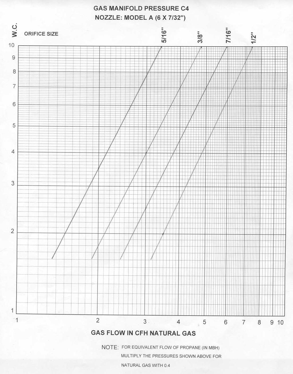
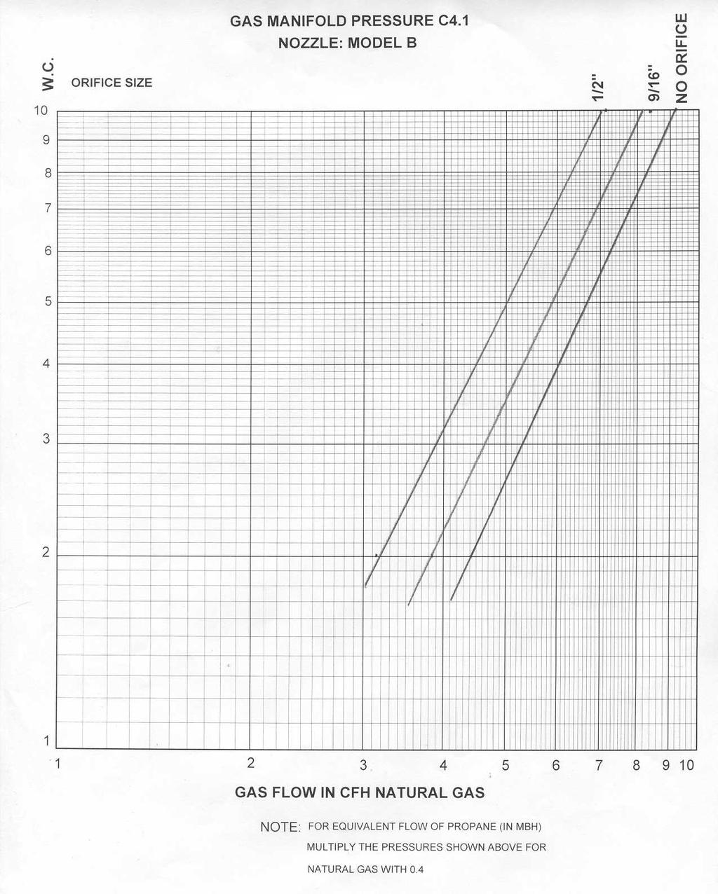
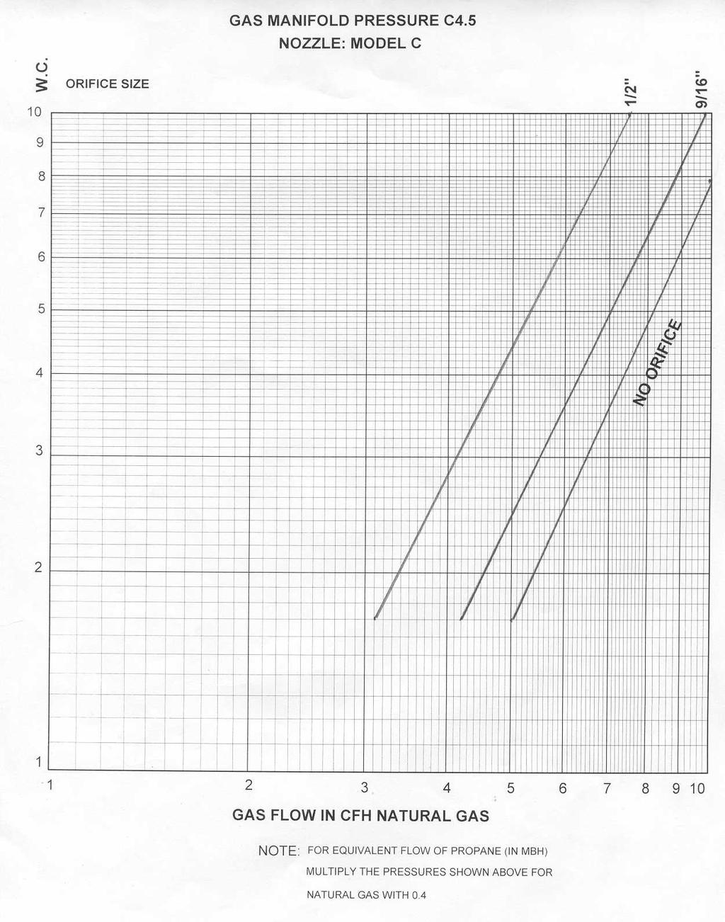
5 BURNER SPECIFICATIONS MODEL C 4 HIGH FIRE MBH BURNER MODEL MAX MIN LOW FIRE MBH GAS PRESSURE INCH W.C GAS TRAIN CONNECTION MOTOR MIN N P N P HP POWER SUPPLY AMPS. 115/1/60 C4-N ¾ ¾ 1/3 115/1/ C4.1-N ¾ ¾ 1/3 115/1/ C4.5-N ¾ ¾ 1/3 115/1/ FOR PROPANE. SAME FIRING RATE. SUFFIX P REPLACES N. MOTOR OPTIONS INCLUDE. 3 PHASE. TENV. AND 40 DEGREE BEARINGS. Page 3
6 BURNER MODEL DESIGNATION BURNER MODEL & SIZE: C4.1-N-03-H4.07 FUEL: N-NATURAL GAS P-PROPANE MOTOR HORSEPOWER: 03-1/3 HP GAS SYTEM: (See Gas Systems) GAS TRAIN SIZE: 07-3/ Page 4
7 INSTALLATION INSTRUCTIONS GENERAL The equipment shall be installed in accordance with the Provincial Installation Requirements, or in their absence, the most recent edition of Can/CGA-B149 installation code shall prevail. The heat transfer surfaces of the furnace or boiler should be cleaned before the burner is mounted. Consult your local gas utility company regarding any special requirements in the preparation of the furnace or boiler. VENTING REQUIREMENTS Flue pipe, double acting barometric damper, draft hood, or vent should not be smaller than recommended by the furnace or boiler manufacturer. The size is typically represented by the dimension of the smoke outlet. If existing flue pipe is used, it must be cleared of all soot and other deposits. GAS REQUIREMENTS Maximum inlet pressure to gas train must not exceed 14 W.C. for Natural Gas or 11 W.C. for LP Gas. For maximum capacity, natural gas minimum supply pressure must be 7 W.C. for C4.1 and C4.5 models, and 4 W.C. for C4 models. In any case, the gas pressure indicated on the firing rate label of the burner must prevail. COMBUSTION AIR SUPPLY The boiler room in which the burner is located must be provided with an adequate fresh air supply to assure proper combustion. The installation code Can/CGA-B149 specifies these requirements. WIRING The burner is prewired at the factory as far as practical. Refer to burner wiring diagram for complete wiring information and study thoroughly before making any connections. Make sure all connections on the flame safeguard base are tight, as they may have been loosened during shipment. Power to the burner must be 120 volts. All wiring, including electrical ground, must be done in accordance with Local Code requirements, or in the absence of local codes, with the Canadian Electric Code, CSA C22.1. Burner electric power should be provided from a separate fused disconnect switch located in the Boiler Room. BURNER GASKET Attach a rope gasket or sheet gasket to the burner mounting flange to prevent leakage of combustion gases into the Boiler Room. BURNER MOUNTING Attach burner to the boiler frontplate by firmly tightening nuts on the mounting studs or clamps so that a rigid installation is accomplished. Make sure burner is level before tightening clamps. Support burner housing to base or floor. Provide a minimum clearance of 30 around the burner for proper servicing. FLAME SAFEGUARD A manufacturer s instruction manual on the flame safeguard is included separately in this manual. Page 5
8 STARTING THE BURNER When starting the burner, open the manual gas shut-off valve, turn on the power and adjust the thermostat to the desired setting. This burner is equipped with interlocking safety devices. In the event of a flame failure or combustion air blockage, the burner will lock out. To restart, read the instructions on the flame safeguard or push the reset button, depending on the flame safeguard model. CLOSE DOWN PROCEDURES When closing the burner down for an extended period, turn off the power and close the manual gas shut-off valve. EMERGENCY PROCEDURES shut-off valve. In case of emergency turn off all power and close the manual Page 6
9 GAS PIPING. The gas control size furnished and the minimum gas pressure required at the inlet to the controls is shown in the Burner Material List contained in the manual shipped with the burner. Gas piping should be sized to provide the required minimum pressure at the main manual shutoff when operating at the maximum input. Consult your local utility on any questions regarding gas pressure, piping pressure drop allowable and local piping requirement. Gas piping should be installed in accordance with the installation code for gas burning appliances and equipment, CAN/CGA-B149, and any other local codes that may apply. All gas piping shall be tested after installation with air pressure or inert gas in accordance with the above-mentioned code. The installer shall identify the main manual shut-off valve. Page 7
10 COMBUSTION CHAMBER. The C burner is an Inshot design burner. It does not depend on refractory for its flame retention or combustion efficiency. Although refractory has a positive effect on combustion and therefore flame length. The boiler refractory primarily serves to protect those parts of the boiler that are exposed to excessive heat. The following combustion chamber illustrations are general in nature and show approximate chamber dimensions and recommended type and thickness of insulating materials. CAUTION It is the installing contractors responsibility to include and provide expansion joints, refractory supports, wall ties, etc as may be required for a proper installation. Consult your refractory supplier for contraction details and requirements for these items. The burner head must be wrapped with high temperature rope before the plastic refractory is put in place. Seal between the burner mounting flange and boiler front plate with high temperature rope gasket. RECOMMENDED FIREBOX DIMENSIONS 100 FIREBOX DIMENSIONS IN INCHES Length Width BURNER CAPACITY IN MBH Page 8


11 FIREBOX BOILER fired through front of base. FIREBOX BOILER fired through door. SCOTCH MARINE BOILER. AIR HEATER Page 9
12 TEMPLATE DIMENSIONS MOUNTING FLANGE OUTLINE (4) 3/8 STUDS B A B BURNER MODEL BURNER HEAD A B DIAMETER C C C ALL DIMENSIONS ARE IN INCHES. Page 10
13 BURNER PRESTART-UP CHECKLIST CAUTION This manual has been prepared as a guide in burner start- up operations. It is written for the startup specialist who are thoroughly qualified both by training and experience. 1. GENERAL - The following data is pertinent to the burner start-up and should be carefully studied before any attempt to operate the burner is made. The following is a part of the manual shipped with the burner. Burner Material List Burner Wiring Diagram Flame Safeguard/Ignition Module Bulletin Misc. Manufacturer's Data on Controls, Valves, Regulators, etc. NOTE The above cited manual is ONE OF A KIND in that it contains material covering your SPECIFIC burner. To replace it, considerable time, special handling and significant costs are involved. Accordingly, it should be handled with care and kept in a location free of dust and moisture. 2. IDENTIFICATION OF CONTROLS - Review the burner wiring diagram and operating sequence. Study these items and identify the various controls. NOTE Do not proceed with start-up unless all applicable check list items in Part IV and preliminary adjustment requirements in Part V have been satisfied. Be certain combustion chamber, flues, and surrounding areas are free of GAS accumulations, and other combustibles such as paint thinners, cleaning solutions, etc. An explosimeter (Mine Safety Appliances Co. Model No. 2A or equivalent) may be used to make this determination. WARNING 3. REVIEW BURNER MATERIAL LIST IN THE INSTRUCTION MANUAL AND NOTE THE FOLLOWING INFORMATION: A. Firing rate (MBTU) B. Cubic feet of gas per hour (CFH) C. BTU per cubic foot (BTU/CF) D. Required gas pressure at control inlet (inches W.C.) E. Required gas pressure at manual leak test valve (inches W.C., taken at port of valve.) The above information is pertinent to setting up the burner. Page 11
14 LINKAGE ADJUSTMENT: High/Low Control or On/Off Control with Low Fire Start With the burner power off, loosen the linkage rod in the damper arm ball joint connector. Move the damper arm so that the low fire stop is between the 25 and 50% mark on the damper quadrant. Tighten the linkage rod and move the actuator arm against the spring action to the full open position. The low tire stop should indicate between 75% and 100% on the damper quadrant. If the damper arm travels too much, move the linkage arm away from the damper shaft on the damper arm and repeat above-mentioned procedure. If the damper arm travels not far enough, move the linkage arm to the damper shaft on the damper arm. Start the burner. In high fire, take a meter reading and if necessary, readjust the outlet pressure of the regulator. Now check the excess air and readjust the damper position by readjusting the linkage rod. Mark the damper position on the quadrant. In low fire position, take a meter reading and readjust the low fire position on the actuator (see attached manufacturers instructions). Check the excess air. If damper needs readjustment in low fire, go back to high fire and readjust the position of the ball joint connector. Again, towards the shaft means more closed in low fire position and away from the shaft means more open n low fire position. Check high fire and low fire positions again and adjust low fire stop. Page 12
15 Page 13
16 INITIAL START UP 1. Make sure burner power switch is off and manual main and pilot valves are closed. 2. Make proper settings on limit controls. 3. Open the fire door of the boiler. 4. Turn on burner power switch momentarily to check blower rotation. 5. Check gas tightness of main and pilot safety shut off valves (if used) by connecting a pressure gauge to the pressure tap located between the safety shut-off valve and the test-firing valve. When the test firing valves are closed and the manual shut-off valves are opened, no pressure rise should show on the pressure gauge. 6. Open the air damper approximately 3/4 for on/off burners. For H/L and modulating burners, open-air damper 1/4 in low position of the actuator lever, allowing the damper to travel to 3/4 in high position of the actuator lever. (These settings are factory made). Turn on the burner switch, while the main and pilot gas firing valves are closed. After the prepurge the ignition transformer and solenoid valves will be energized. Observe the ignition spark for proper location and firmness. After the trial for ignition time, the ignition transformer and solenoid valve are de-energized and the burner will lock out. 7. Open the pilot test firing valve and turn on the burner switch, while the manual main shut-off valve stays closed. After the prepurge, the ignition transformer and the pilot solenoid valve are energized. Observe the pilot flame and if necessary, adjust the pilot pressure regulator to obtain a stable flame with the highest steady flame signal. For flame signal readings, see attached flame safeguard manual. With the main manual shut-off valve still closed, the flame safeguard will lock out after approximately 10 seconds, only with high/low and modulating burners, which use an interrupted pilot. Repeat the ignition cycle a few times to ensure a fast igniting and stable pilot flame. 7A. With direct spark ignition test and observe the electric spark, with a closed main manual shut off valve. In this case, the flame safeguard will tolerate only 4 seconds for observation of the spark, before it locks out. 8. Open the main manual shut-off valve and set the high/low limit switch and the modulating controller so that after establishing a main flame, the burner will travel to high fire. Start the burner, in high fire, check the manifold pressure with the required pressure for the firing rate, (see suggested inspection list) and if necessary, adjust pressure regulator. Readjust the damper if fire looks too lean or too rich. 9. **Close boiler firing door. Take a gas meter reading and readjust manifold gas pressure if necessary. Take a CO2 or 02 and a CO reading. CO2 should be between 8.5 and 9.5% and 02 should not be more than 5%, both with a maximum CO reading of.04%. Readjust air damper accordingly. **Important Note: To be used as guidelines only. Readings will vary according to actual conditions and equipment being fired. Page 14
17 10. With high/low and modulating burners, mark the high air damper position and set the high/low limit control or modulating control so that the burner travels to low position. Visually adjust the input adjuster on the main gas shut-off valve actuator if low fire is too rich or too lean. Take a gas meter reading and readjust the input adjuster according to the required low fire input, which will be about 1/3 of the high firing rate but not less than indicated in the specifications table. In order to keep the high fire setting unchanged when adjusting the low fire air damper position, drive the burner to high fire, change the positioning of the linkage as indicated in Low Fire Adjustment, drive the burner back to low fire and check the CO2 or 02 readings. Repeat this procedure until a satisfactory setting is obtained. 11. Make sure all linkage connections are tight and check the readings in high and low fire 12. Reset controller and limits to their desired settings. CAUTION Do not adjust flame visibly. Instruments are the only safe and reliable means to determine the proper adjustments. Page 15
18 BURNER SAFETY CHECK 1. Start and stop burner several times to insure proper operation. 2. Check operation of combustion safeguard control by simulating a flame failure, making certain the burner locks out in safety within the proper time. See flame safeguard/ignition module instructions for procedure. 3. Check operation of the air flow switch, making certain fuel valve closes when the air flow diaphragm switch open. 4. Set the high limit control 2 to 3 psi or 10 degrees F. to 15 degrees F. higher than the desired operating pressure or temperature. Set the operating control pressure or temperature higher than the high limit control for this test. Permit burner to run until desired HIGH LIMIT pressure or temperature is indicated and then adjust high limit control, if necessary, to shut off the burner at the desired high limit pressure or temperature. 5. Reset operating control to desired pressure or temperature. Permit burner to run until it is shut off by the operating control. Adjust operating control, if necessary until it causes burner to stop and start within desired range. 6. With the burner running, open the blow-down valve on the low water cutoff (if used). The burner should shut off immediately. The burner should restart automatically when the proper level of water in the low water cutoff is reestablished. 7. Conduct minimum pilot turn down test, reduce gas pressure to pilot with manual shutoff cock to the point pilot flame is extinguished or fails to prove. Increase gas flow slightly. Main flame must be ignited with this pilot flame. 8. The following readings should be taken and recorded after final adjustments have been made. A Burner input (CFH gas) B. Percent C02 or 02 C. CO indication D. Stack temperature E. Firebox pressure F. Fuel pressure (in. W.C.- gas) (main and pilot) G. Voltage to burner 9. Give instruction to owner (operator). WARNING Should overheating occur : (1) Shut off the manual gas control(s) to the burner. (2) Do Not shut off the control switch to the pump or blower. Page 16
19 GENERAL MAINTENANCE 1. Make certain combustion chamber and flues are purged of any unburned fuel before attempting to start burner following an OFF period due to any burner problems. 2. Always follow the Burner Operating Instructions in turning the burner OFF or ON. 3. Make certain that all electrical connections are secure, including the flame safeguard/ignition module relay mounting connections. 4. Maintenance of flame safeguard/ignition module control, and other such burner components, should be preformed in accordance with instructions contained in the manufacturer s bulletin. YEARLY MAINTENANCE Preferable before start of heating season. 1. Remove blower motor and blower wheel assembly and clean. 2. Remove gas manifold assembly and clean. 3. Remove pilot/sensor and clean. 4. Clean all inside surfaces of blower scroll. 5. Make repairs to combustion chamber. 6. Check operation of all limit and operating controls. 7. Tighten all screws holding components and conductors. 8. Check combustion. PREVENTIVE MAINTENANCE 1. Visually inspect for dirt deposits on blower wheel. 2. Check that blower wheel is not loose on motor shaft. 3. Check that air flow switch is working properly. 4. Check the combustion chamber for loose bricks and cracks. 5. Oil both bearings of blower motor as directed by decal located on motor housing. 6. Always keep cover on control cabinet, except during servicing. 7. Check operation of flame safeguard/ignition module as per starting instructions. 8. Check limit and operating control Page 17
20 BURNER DIMENSIONS D B GAS CONNECTION "L" J 4 x (K) C A M F E H G BURNER MODEL A B C D E F G H J K L M C ¼ 12-1/2 5 1/2 or /2 9-1/2 5-5/8 1/2 3/4 7 C ¼ 12-1/2 5-1/2 or /2 9-1/2 5-5/8 1/2 3/4 7 C /2 4 ¼ 12-1/2 5-1/2 or /2 9-1/2 5-5/8 1/2 3/4 7 AIR DAMPER GAS INLET MOUNTING FLANGE HOUSING COVER BURNER HOUSING AIR FLOW SWITCH BLAST TUBE ASSEMBLY IGNITION TRANSFORMER AIR INLET SCREEN BLOWER WHEEL FAN MOTOR Page 18
21 C4 BURNER ASSEMBLY IGNITION ELECTRODE 1/16" TO 1/8" 3.875" 1" 1-3/4" RETENTION PLATE GAS MANIFOLD GP COMBUSTION EQUIPMENT INC. CAMBRIDGE, ONTARIO TITLE MODEL PR DRAWER SETTINGS SIZE DATE A SEPT 8, 08 DWG NO. C4 BURNER HEAD ASSY BY: RR SCALE: 1 : 1 ALL DIMENSIONS ARE INCHES SHEET: 1 OF 1 REV A C4 BURNER ASSEMBLY IGNITION ELECTRODE 1/16" TO 1/8" 3.875" 1" 1-3/4" RETENTION PLATE GAS MANIFOLD GP COMBUSTION EQUIPMENT INC. CAMBRIDGE, ONTARIO TITLE MODEL ST DRAWER SETTINGS SIZE DATE A SEPT 8, 08 DWG NO. C4 BURNER HEAD ASSY BY: RR SCALE: 1 : 1 ALL DIMENSIONS ARE INCHES SHEET: 1 OF 1 REV A
22 P/N 033 MAIFOLD TUBE T68-7C P/N FR/ELECTRODE HOLDER P/N 042 ORIFICE RETENTION PLATE P/N 036 AIR SCOOP P/N 029 MANIFOLD BLOCK P/N 044-? NOZZLE P/N 035 FOR 5-1/2" NOSE P/N FOR 8" NOSE PILOT TUBE FLAME ROD/ELECTRODE HOLDER X 1/2" BALL RETAINING SCREW P/N 043 PILOT DEFLECTOR NY CHECK BALL FW CHECK WASHER P/N FOR 5 1/2" NOSE P/N FOR 8" NOSE NOZZLE TUBE GP COMBUSTION EQUIPMENT INC. CAMBRIDGE, ONTARIO TITLE MANIFOLD ASSEMBLY PR SIZE DATE A SEPT 8, 08 DWG NO. 032 BY: RR SCALE: 1 : 1 ALL DIMENSIONS ARE INCHES SHEET: 1 OF 1 REV A P/N 033 MANIFOLD TUBE T68-7C P/N ELECTRODE RETENTION HOLDER PLATE P/N 042 ORIFICE FLAME ROD P/N 029 MANIFOLD BLOCK ELECTRODE P/N 044 NOZZLE FLAME ROD/ELECTRODE HOLDER P/N FOR 5 1/2" NOSE P/N FOR 8" NOSE NOZZLE TUBE GP COMBUSTION EQUIPMENT INC. CAMBRIDGE, ONTARIO TITLE MANIFOLD ASSEMBLY ST SIZE DATE DWG NO. BY: A SEPT 8, RR SCALE: 1 : 1 ALL DIMENSIONS ARE INCHES 1 OF 1 SHEET: REV A
23
24
25
26 No. QTY DESCRIPTION GP PART No. OR VENDOR No. 1 1 COMBUSTION HEAD SEE BELOW 4 1 NOZZLE SEE BELOW 6 1 ORIFICE (NOT SHOWN) SEE MAT. LIST 9 1 HOUSING WELD ASSY AIR DAMPER ASSY DAMPER SHAFT TOP COVER HOUSING AIR INLET CONE SEE BELOW 15 1 MOTOR MOUNTING PLATE RETENTION PLATE ASSY MANIFOLD PILOT TUBE ASSY SEE BELOW 20 1 ELECTRIC MOTOR 1/3 HP-56C IGNITION TRANSFORMER Q652B AIRFLOW SWITCH AFS-A 26 1 LINKAGE ARM CONTROL QUADRANT SIGHT GLASS SIGHT GLASS RETAINER SIGHT GLASS GASKET IGNITION ELECTRODE FLAME ROD JUNCTION BOX K 45 1 BLOWER WHEEL SEE BELOW 46 2 ELECTRODE HOLDER T68-7C 47 1 AIR INLET COVER PLATE HOUSING COVER PLATE ELECTRODE HOLDER PRE-MIX SCOOP MANIFOLD ASSEMBLY ITEM 1) 5.5" NOSE 1) 8" NOSE 4) NOZZLE 14) CONE 19) TUBE 5.5" 19) TUBE 8" 45)WHEEL C A C B C C GP COMBUSTION EQUIPMENT INC. CAMBRIDGE, ONTARIO TITLE MODEL C4,C4.1,C4.5 CUSTOMER:TYPICAL SIZE DATE A SEPT 1, 04 DWG NO. ML-4-TYP BY: RR SCALE: NTS ALL DIMENSIONS ARE INCHES SHEET: 1 OF 1 REV A
Type CG Series Forced Draft Gas Burner
 Type CG Series Forced Draft Gas Burner Designed and built by Canadians for Canadian Winters By PENDELL BURNERS Office & Plant Address: 155 Regina Road, Unit #3 Woodbridge, Ontario L4L 8L9 Telephone: (416)
Internet Version for Reference Only INDUCED DRAFT COMMERCIAL WATER HEATERS SUPPLEMENT INSTRUCTIONS TO PART #
 INDUCED DRAFT COMMERCIAL WATER HEATERS SUPPLEMENT INSTRUCTIONS TO PART #238-39387-00 THIS INSTRUCTION SUPPLEMENT IS ONLY INTENDED TO GIVE INSTALLATION INSTRUCTIONS AND INFORMATION RELATED TO THE INDUCED
FGR. Installation, Operation and Startup Instruction Manual FOR FLUE GAS RECIRCULATION SYSTEM. FGR-8 through FGR-22 (25 HP to 1000 HP)
") FGR Installation, Operation and Startup Instruction Manual FOR FLUE GAS RECIRCULATION SYSTEM FGR-8 through FGR-22 (25 HP to 1000 HP) Gas, Light Oil or Combination MANUFACTURED BY JOHN ZINK COMPANY, LLC
FGR Installation, Operation and Startup Instruction Manual FOR FLUE GAS RECIRCULATION SYSTEM FGR-8 through FGR-22 (25 HP to 1000 HP) Gas, Light Oil or Combination MANUFACTURED BY JOHN ZINK COMPANY, LLC
Installation & Service Instructions for Jackson & Church Flexaire Packaged Furnaces SDF-125 thru SDF-400 Gas Firing
 Installation & Service Instructions for Jackson & Church Flexaire Packaged Furnaces SDF-125 thru SDF-400 Gas Firing Important: To protect the unit and avoid damage to the heat exchanger, the blower speed
Indirect gas-fired air heater
 Indirect gas-fired air heater SERIES HD INSTALLATION AND SERVICE MANUAL MANUFACTURED BY : BROTHERS LIMITED WARNING Improper installation, modification, adjustment or maintenance may cause damage, injury
Power Flame Incorporated
 Power Flame Incorporated HAC INSTALLATION AND OPERATION MANUAL THE POWER TO MANAGE ENERGY 2001 South 21 st Street, Parsons, Kansas 67357 Telephone 620-421-0480, Fax 620-421-0948 Web Site: www.powerflame.com
PVE SERIES POWER VENTER SYSTEM MANUAL
 PVE SERIES POWER VENTER SYSTEM MANUAL Contents Page I. Typical Venting System Components 2 II. System Operation 3 III. Power Venter Sizing 3,4 IV. Installation Safety Instructions 5,6 V. Installation of
Forced draught natural gas/propane burner
 Installation, use and maintenance instructions GB Forced draught natural gas/propane burner Single stage operation CODE MODEL 20096942 G400 (2) - 11/2015 Original instructions TABLE OF CONTENTS Installation
POWER VENTER SYSTEM. Model: PVO-300, PVO-600
 POWER VENTER SYSTEM Model: PVO-300, PVO-600 Included is one ETL and cetl listed Power Venter to be used primarily with a single 120VAC controlled oil fired furnace, boiler, or water heater. The PVO may
LATTNER BOILER COMPANY 9.5 HP Low-NOx Installation and Start-Up Checklist for Dry Cleaners
 1 1. General Installation Information (to be completed by technician) Date installed: Location (city & state): Cleaner s name: National Board number (boiler): Installed by (company): Installed by (technician):
Installation Instructions
 Model 500-SP OVENPAK Burners Page 2300-S-1 Installation Instructions General Instructions Important: Do not discard packing material until all loose items are accounted for. To prevent damage in transit,
POWER VENTER. Model: PVE Series
 POWER VENTER Model: PVE Series CONTENTS Typical Venting System Components... System Operation... Power Venter Sizing... Installation Safety Instructions... Installation of Power Venter... Connecting Power
SERVICE AND INSTALLATION MANUAL MODELS HDO(H) OIL FOR YOUR SAFETY
 OIL FOR YOUR SAFETY") Bousquet Technologies Inc. 2121, Nobel, Ste Julie, Quebec, Canada, J3E1Z9 SERVICE AND INSTALLATION MANUAL MODELS HDO(H) OIL Oil-Fired air heater for industrial and commercial use. FOR YOUR SAFETY Do not
Bousquet Technologies Inc. 2121, Nobel, Ste Julie, Quebec, Canada, J3E1Z9 SERVICE AND INSTALLATION MANUAL MODELS HDO(H) OIL Oil-Fired air heater for industrial and commercial use. FOR YOUR SAFETY Do not
Power Flame Incorporated CMAX. Installation and Operation Manual
 Power Flame Incorporated CMAX Installation and Operation Manual Cmax Installation & Operation Manual - POWER FLAME INCORPORATED POWER FLAME MODEL Cmax BURNER For use by Qualified Service Personnel Only
24 VAC SYSTEM CONTROL KIT
 24 VAC SYSTEM CONTROL KIT Model: CK-91F and CK-91FG Designed for use with the SWG Series Power Venter for controlling Natural Gas or L.P. Gas draft induced appliances with a 24 VAC Gas Valve and a 30-millivolt
OPERATING AND MAINTENANCE MANUAL
 OPERATING AND MAINTENANCE MANUAL NVPOM-0104 TABLE OF CONTENTS Section Page 1 SPECIFICATIONS...1 1.1 Nova Plus Specifications...1-1 1.2 Warranty...1-2 2 GENERAL BURNER DESCRIPTION...2 2.1 Burner...2-1 2.2
USER S INFORMATION MANUAL
 USER S INFORMATION MANUAL UPFLOW/HORIZONTAL & DOWNFLOW TWO STAGE INDUCED DRAFT GAS FURNACES Recognize this symbol as an indication of Important Safety Information If the information in this manual is not
INSTALLATION AND OPERATION MANUAL GAS SKILLETS MODELS: GTS-30 GTS-40
 INSTALLATION AND OPERATION MANUAL GAS SKILLETS MODELS: GTS-30 GTS-40 CROWN FOOD SERVICE EQUIPMENT LTD. 70 OAKDALE ROAD, DOWNSVIEW, (TORONTO), ONTARIO, CANADA, M3N 1V9 TELEPHONE: (416) 746-2358, FAX: (416)
Installation and Service Instructions. name
 Installation and Service Instructions Unipower A-Series Gas Burners In the United States, installation must conform with local codes or in the absence of local codes, with the National Fuel Gas Code, ANSI
Single stage operation forced draught natural gas/propane burner
 Installation & Operating Manual Single stage operation forced draught natural gas/propane burner The following pages contain information, descriptions and diagrams for the proper installation and wiring
Power Flame Incorporated
 Power Flame Incorporated SUGGESTED SPECIFICATION FOR MODEL NVC2 THRU NVC6 ULTRA LOW NOx GAS BURNERS SUB 9 PPM NOx WITH CONTROLINKS CONTROLS THE POWER TO MANAGE ENERGY 2001 South 21st Street, Parsons, Kansas
40 SERIES GAS BURNER MODEL 400 NATURAL GAS/PROPANE INSTALLATION INSTRUCTIONS AND OWNER S HANDBOOK
 40 SERIES GAS BURNER MODEL 400 NATURAL GAS/PROPANE INSTALLATION INSTRUCTIONS AND OWNER S HANDBOOK CAUTION: All gas burners MUST be installed by trained and licensed technicians. WARNING: Installation of
PART 0 A/E INSTRUCTIONS 0.01 DESIGN REQUIREMENTS
 PART 0 A/E INSTRUCTIONS 0.01 DESIGN REQUIREMENTS A. General: 1. To obtain maintenance and repair standards for boiler burners (Section 15555A) and boiler tubes (Section 15555B), contact the DPS Project
A-8-01 Typical questions and answers on the boiler specifications on tender and boiler contract documents
 Boiler specifications A-8-01 Typical questions and answers on the boiler specifications on tender and boiler contract documents Burner General: Q. Burner and burner safeguards shall comply with the CGA
GENERAL BASIC INSTALLATION INSTRUCTIONS DIRECT FIRED HOT WATER BOILERS PARKER BOILER CO.
 GENERAL BASIC INSTALLATION INSTRUCTIONS DIRECT FIRED HOT WATER BOILERS PARKER BOILER CO. GBI 201-5 3C For a proper installation and in order to receive the best in operating life and efficiency from your
Packaged Gas/Electric Units. Owner s Guide to Operating and Maintaining Your Gas/Electric Unit
 Packaged Gas/Electric Units Owner s Guide to Operating and Maintaining Your Gas/Electric Unit ELECTRICAL SHOCK HAZARD. FIRE OR EXPLOSION HAZARD Disconnect power at fuse box or service panel before performing
QHT Manual for: SU-2A Gas Burner
 1 QHT Manual for: SU-2A Gas Burner 50,000 BTU/H to 250,000 BTU/H The burner shall be used only with NATURAL GAS or LP GAS. Warning: If the following instructions are not followed exactly, a fire or explosion
Fig. 1 - Unit PGD4, PGS4, WPG4
 OWNER S MANUAL 14 SEER Single -Package Air Conditioner and Gas Furnace System with R -410A Refrigerant Single Phase 2 to 5 Nominal Tons Three Phase 3 to 5 Nominal Tons PGD4andPGS4SeriesE,WPG4SeriesB Fig.
INSTALLATION AND SERVICE INSTRUCTIONS
 INSTALLATION AND SERVICE INSTRUCTIONS ECONOMITE MODEL F400B-33 Gas Conversion Burner The ECONOMITE F400B-33 conversion burner with intermittent spark ignited pilot is adaptable to most gas utilization
Copyright 2009 Power Flame Incorporated
 Power Flame Incorporated Installation and Operation Manual Ultra CMax Copyright 2009 Power Flame Incorporated 2001 South 21 st Street, Parsons, KS 67357 Telephone: 620-421-0480 FAX: 620-421-0948 Website:
USER S INFORMATION MANUAL (2,4)SG13B
SG13B") USER S INFORMATION MANUAL (2,4)SG13B Series Gas Heating/Electric Cooling Package Unit Congratulations......your outdoor heating/cooling package unit is a valuable piece of equipment, designed and manufactured
USER S INFORMATION MANUAL (2,4)SG13B Series Gas Heating/Electric Cooling Package Unit Congratulations......your outdoor heating/cooling package unit is a valuable piece of equipment, designed and manufactured
Owner s Information Manual
 48ES---A and 48VL---A Comfort and Performance 13 and 14 SEER Single Packaged Air Conditioner and Gas Furnace System With Puron (R---410A) Refrigerant Single and Three Phase 2---5 Nominal Tons (Sizes 24---60)
Conversion Instructions Logano G234X. Gas boiler. Please read carefully before installing and servicing. Gas boiler
 Gas boiler UPON COMPLETION OF THE INSTALLATION THE INSTALLER MUST INSTRUCT THE OWNER AND OPERATOR ON THE FUNCTIONALITY AND THE PROPER OPERATION OF THE BOILER AND THE HEATING SYSTEM. INSTALLER MUST REVIEW
USER S, MAINTENANCE and SERVICE INFORMATION MANUAL
 CONTENTS SAFETY INFORMATION................ 2 FOR YOUR SAFETY...................... 2 SYSTEM OPERATION.................. 2 THERMOSTATS.......................... 2 INTERMITTENT IGNITION DEVICE..........
ZG Shown READ ALL INSTRUCTIONS IN THIS MANUAL AND RETAIN FOR FUTURE REFERENCE WARNING
 See unit nameplate for manufacturer and address. 507258-04 7/2018 Supersedes 10/2017 ZG 036, 048, 060, 072, 074 (3, 4, 5 and 6 Tons) ZG 092, 102, 120, 150 (7-1/2, 8-1/2, 10 and 12 Tons) ROOFTOP UNITS ZG
Power Flame Incorporated
 Power Flame Incorporated SUGGESTED SPECIFICATION FOR MODEL NVC ULTRA LOW NOx GAS BURNERS SUB 9 PPM NOx THE POWER TO MANAGE ENERGY 2001 South 21st Street, Parsons, Kansas 67357 Telephone: 620-421-0480,
OPERATING INSTRUCTIONS MANUAL (Please retain for future reference) FVN/P-400 INDIRECT FIRED SPACE HEATERS
 FVN/P-400 INDIRECT FIRED SPACE HEATERS") OPERATING INSTRUCTIONS MANUAL (Please retain for future reference) For FVN/P-400 INDIRECT FIRED SPACE HEATERS CERTIFIED FOR USE IN CANADA AND U.S.A. As per Standard ANSI Z83.7/CSA 21.4 2000 Gas Fired Construction
OPERATING INSTRUCTIONS MANUAL (Please retain for future reference) For FVN/P-400 INDIRECT FIRED SPACE HEATERS CERTIFIED FOR USE IN CANADA AND U.S.A. As per Standard ANSI Z83.7/CSA 21.4 2000 Gas Fired Construction
Bryan Flexible Water Tube. Ultra-High Efficiency Condensing Hot Water Boilers. 3,000,000 BTUH Natural Gas Fired
 Form No. 8700 Bryan Flexible Water Tube TM Triple-Flex Series Ultra-High Efficiency Condensing Hot Water Boilers 3,000,000 BTUH Natural Gas Fired Minimum 90% Thermal Efficiency at 160 F Return with 20
PrecisionTemp Shower-Mate
 Shower-Mate Instantaneous Gas Water Heater Installation and Operating Instructions The Shower-Mate is a power vented automatic instantaneous water heater designed to be installed in ventilated marine applications.
MODEL HS115-3, HS115-4 & HS115-5 WIRING DIAGRAM ADDENDUM
 TJERNLUND PRODUCTS, INC. 1601 Ninth Street White Bear Lake, MN 55110-6794 PHONE (800) 255-4208 (651) 426-2993 FAX (651) 426-9547 Visit our web site www.tjernlund.com MODEL HS115-3, HS115-4 & HS115-5 WIRING
OPERATING INSTRUCTIONS MANUAL (Please retain for future reference) FVN/P-400 INDIRECT FIRED SPACE HEATERS
 FVN/P-400 INDIRECT FIRED SPACE HEATERS") OPERATING INSTRUCTIONS MANUAL (Please retain for future reference) For FVN/P-400 INDIRECT FIRED SPACE HEATERS CERTIFIED FOR USE IN CANADA AND U.S.A. As per Standard ANSI Z83.7/CSA 21.4 2000 Gas Fired Construction
OPERATING INSTRUCTIONS MANUAL (Please retain for future reference) For FVN/P-400 INDIRECT FIRED SPACE HEATERS CERTIFIED FOR USE IN CANADA AND U.S.A. As per Standard ANSI Z83.7/CSA 21.4 2000 Gas Fired Construction
DIRECTIVE NO: D-B
 DIRECTIVE NO: D-B6 100604 1 LOW PRESSURE THERMAL FLUID PLANT AUTOMATED CONTROL SYSTEMS Date of Issue: June 4, 2010 General Details This directive is being issued to owners, licensed contractors, consulting
INSTALLATION GUIDE Dual Fuel Ranges
 INSTALLATION GUIDE Dual Fuel Ranges Contents Wolf Dual Fuel Ranges......................... 3 Safety Instructions............................ 4 Dual Fuel Range Specifications.................. 5 Dual Fuel
KGA092 SHOWN READ ALL INSTRUCTIONS IN THIS MANUAL AND RETAIN FOR FUTURE REFERENCE WARNING
 See unit nameplate for manufacturer and address. 506380 01 11/2009 KGA024, 030, 036, 048, 060, 072 (2, 2 1/2, 3, 4, 5, and 6 Tons) KGA092, 102, 120, 150 (7 1/2, 8-1/2, 10, and 12 Tons) KGA180, 210, 240,
User s Information Manual Models: 45, ,000 Btu/hr
 SBR-USER_100161678_2000017137_Rev C User s Information Manual Models: 45,000-260,000 Btu/hr If the information in this manual is not followed exactly, a fire or explosion may result causing property damage,
SECTION WATER-TUBE BOILERS
 PART 1 - GENERAL 1.1 RELATED DOCUMENTS A. Drawings and general provisions of the Contract, including General and Supplementary Conditions and Specification Sections, apply to this Section. B. Related Sections
24 VAC SYSTEM CONTROL KIT
 24 VAC SYSTEM CONTROL KIT Model: CK-43 Tubing MG1 Barometric Draft Control The CK-43 is designed for use with the SWG Series Power Venter for controlling Natural Gas and L.P. Gas Draft Induced appliances.
Engineering Bulletin. Gas Heat. for M-Series and T-Series Climate Changer Air Handlers CLCH-PRB010-EN. March 2004
 Engineering Bulletin Gas Heat for M-Series and T-Series Climate Changer Air Handlers March 2004 CLCH-PRB010-EN Preface Gas heat can be a good heating option for any of the following applications: Climates
Bosch 80% AFUE Gas Furnace BGS80 Model
 Bosch 80% AFUE Gas Furnace BGS80 Model 4-Way Multipoise Category I Fan-Assisted Furnace User's Information Manual 3124627 2 Bosch 80% AFUE Gas Furnace User's Information Manual Data subject to change 06.2018
ClearFire. Startup Guide. Model CFH. Horizontal Steam Boiler
 ClearFire Model CFH Horizontal Steam Boiler Startup Guide 750-293 www.cleaverbrooks.com Improper installation, adjustment, service, or maintenance can cause equipment damage, personal injury, or death.
USER'S INFORMATION MANUAL
 USER'S INFORMATION MANUAL WARNING: If the information in this manual is not followed exactly, a fire or explosion may result causing property damage, personal injury or loss of life. Do not store or use
Packaged Gas/Electric
 Packaged Gas/Electric Units Owner's Guide to Operating and Maintaining Your Gas/Electric Unit ELECTRICAL SHOCK HAZARD. FIRE OR EXPLOSION HAZARD Failure to follow this warning can result in Disconnect power
Multi-Function Cooktop
 INSTALLATION GUIDE Multi-Function Cooktop Contents Wolf Multi-Function Cooktop.................... 3 Multi-Function Cooktop Specifications............ 4 Multi-Function Cooktop Installation...............
southbend A MIDDLEBY COMPANY INSTALLATION AND OPERATION MANUAL CG214 (E) CG314 (E) CG414 (E) CG220 (E) CG320 (E) CG325 (E) GAS BOILERS MODELS:
 CG314 (E) CG414 (E) CG220 (E) CG320 (E) CG325 (E) GAS BOILERS MODELS:") INSTALLATION AND OPERATION MANUAL GAS BOILERS MODELS: CG214 (E) CG314 (E) CG414 (E) CG220 (E) CG320 (E) CG325 (E) southbend A MIDDLEBY COMPANY 1100 Old Honeycutt Road Fuquay-Varina, NC 27526 (919) 552-9161
INSTALLATION AND OPERATION MANUAL GAS BOILERS MODELS: CG214 (E) CG314 (E) CG414 (E) CG220 (E) CG320 (E) CG325 (E) southbend A MIDDLEBY COMPANY 1100 Old Honeycutt Road Fuquay-Varina, NC 27526 (919) 552-9161
A. Product Data: Include rated capacities, furnished specialties and accessories.
 BASE BID: SECTION 15542 FUEL-FIRED RADIANT HEATERS PART 1 - GENERAL 1.1 SUMMARY A. Furnish and install a Co-Ray-Vac Low Intensity Vented Infrared Radiant Vacuum Gas Heating System. System must be certified
V SERIES HDR GAS RANGES
 SERVICE MANUAL ONE POWERFUL PACKAGE V SERIES HDR GAS RANGES TOPS Open Top Hot Top Griddle Top Work Surface BASES Standard Oven Convection Oven Cabinet Base - NOTICE - This manual is prepared for use by
ECLIPSE INFORMATION GUIDE
 ECLIPSE INFORMATION GUIDE JUNIOR INDUSTRIAL BURNERS Models 0 & 6 JIB Info 80 0/9 Easy to install and operate. Rugged construction for long life in industrial environments. Protection against overheating
USER S, MAINTENANCE and SERVICE INFORMATION MANUAL
 CONTENTS SAFETY INFORMATION................ 2 FOR YOUR SAFETY....................... 2 SYSTEM OPERATION.................. 2 THERMOSTATS.......................... 2 INTERMITTENT IGNITION DEVICE...........
ASSEMBLY INSTRUCTIONS - NXS SERIES. INFRARED RADIANT TUBE HEATER Single and Two Stage Pull Through System (Negative Pressure)
") ASSEMBLY INSTRUCTIONS - NXS SERIES OWNER / INSTALLER: For your safety this manual must be carefully and thoroughly read and understood before installing, operating or servicing this heater. INFRARED RADIANT
ASSEMBLY INSTRUCTIONS - NXS SERIES OWNER / INSTALLER: For your safety this manual must be carefully and thoroughly read and understood before installing, operating or servicing this heater. INFRARED RADIANT
TGA/KGA024, 030, 036, 048, 060, 072, 090 (2, 2 1/2, 3, 4, 5, 6, and 7 1/2 TONS)
") See unit nameplate for manufacturer and address. 506003 01 5/2009 Supersedes 1/2008 TGA/KGA024, 030, 036, 048, 060, 072, 090 (2, 2 1/2, 3, 4, 5, 6, and 7 1/2 TONS) TGA090, 102, 120, 150, TGA120 SHOWN (7
See unit nameplate for manufacturer and address. 506003 01 5/2009 Supersedes 1/2008 TGA/KGA024, 030, 036, 048, 060, 072, 090 (2, 2 1/2, 3, 4, 5, 6, and 7 1/2 TONS) TGA090, 102, 120, 150, TGA120 SHOWN (7
OPERATING INSTRUCTIONS MANUAL (Please retain for future reference) FVN/P-400 INDIRECT FIRED SPACE HEATERS
 FVN/P-400 INDIRECT FIRED SPACE HEATERS") OPERATING INSTRUCTIONS MANUAL (Please retain for future reference) For FVN/P-400 INDIRECT FIRED SPACE HEATERS CERTIFIED FOR USE IN CANADA AND U.S.A. As per Standard ANSI Z83.7/CSA 21.4 2000 Gas Fired Construction
OPERATING INSTRUCTIONS MANUAL (Please retain for future reference) For FVN/P-400 INDIRECT FIRED SPACE HEATERS CERTIFIED FOR USE IN CANADA AND U.S.A. As per Standard ANSI Z83.7/CSA 21.4 2000 Gas Fired Construction
OPERATING INSTRUCTIONS MANUAL (Please retain for future reference) FVO-400 INDIRECT FIRED SPACE HEATERS
 FVO-400 INDIRECT FIRED SPACE HEATERS") OPERATING INSTRUCTIONS MANUAL (Please retain for future reference) For FVO-400 INDIRECT FIRED SPACE HEATERS CERTIFIED FOR USE IN CANADA AND U.S.A. As per CSA B140.8 Portable Oil Fired Heaters / CSA B140.02003
OPERATING INSTRUCTIONS MANUAL (Please retain for future reference) For FVO-400 INDIRECT FIRED SPACE HEATERS CERTIFIED FOR USE IN CANADA AND U.S.A. As per CSA B140.8 Portable Oil Fired Heaters / CSA B140.02003
Forced Draft Gas Fired Furnace on McQuay Applied Rooftop Systems
 Installation and Maintenance Manual IM-684-3 Group: Applied Systems Part Number: IM684 Date: January 2004 Forced Draft Gas Fired Furnace on McQuay Applied Rooftop Systems FC ****A* with RM7895A Flame Safeguard
Installation and Service Instructions Economite DS24A
 Installation and Service Instructions Economite DS24A Conversion Burners MADE in the USA In the United States, installation must conform with local codes or in the absence of local codes, with the National
KG 092 SHOWN READ ALL INSTRUCTIONS IN THIS MANUAL AND RETAIN FOR FUTURE REFERENCE WARNING
 See unit nameplate for manufacturer and address. 507350-03 3/2016 Supersedes 9/2015 KG 024, 030, 036, 048, 060, 072, 074, 090 (2, 2-1/2, 3, 4, 5, 6 and 7-1/2 Tons) KG 092, 102, 120, 150 (7-1/2, 8 1/2,
SUPER HIGH EFFICIENCY WATER HEATERS SUPPLEMENT TO INSTRUCTION MANUAL P/N (Replaces pg. 2 in instruction manual.) CONGRATULATIONS!
 CONGRATULATIONS!") SUPER HIGH EFFICIENCY WATER HEATERS SUPPLEMENT TO INSTRUCTION MANUAL P/N 238-44219-00 (Replaces pg. 2 in instruction manual.) CONGRATULATIONS! You have just purchased one of the finest water heaters on
SUPER HIGH EFFICIENCY WATER HEATERS SUPPLEMENT TO INSTRUCTION MANUAL P/N 238-44219-00 (Replaces pg. 2 in instruction manual.) CONGRATULATIONS! You have just purchased one of the finest water heaters on
USER S INFORMATION MANUAL
 USER S INFORMATION MANUAL HOT WATER HEATING BOILERS DOMESTIC WATER HEATERS 150,000-300,000 Btu/hr MODELS EB-EWU-02 IMPORTANT INSTALLER - AFFIX INSTALLATION MANUAL ADJACENT TO THE BOILER CONSUMER - RETAIN
GAS FURNACES G20RE/ G20RXE EXISTING NEG ENGINEERING DATA EXISTING NEG. Typical Applications
 ENGINEERING DATA Typical Applications G20RE and G20RXE WhisperHeat DOWN-FLO GAS FURNACES *78.0% A.F.U.E. 50,000 to 150,000 Btuh Input Add-On Cooling 2 thru 5 Nominal Tons *Isolated Combustion System rating
SYSTEM CONTROL KIT. Model: CK-62. Designed for use on SWG Series Power Vent Hoods for controlling oil fired heating appliances with 120 VAC controls.
 SYSTEM CONTROL KIT Model: CK-62 Designed for use on SWG Series Power Vent Hoods for controlling oil fired heating appliances with 120 VAC controls. ITEMS INCLUDED IN KIT: 1) Junction box with mounted pressure
24 VAC SYSTEM CONTROL KIT
 24 VAC SYSTEM CONTROL KIT Model: CK-92F and CK-92FG Designed for use with the SWG Series Power Venter for controlling Natural Gas or L.P. Gas appliances with a 24 VAC Gas Valve and a 30-millivolt controlled
HORIZONTAL FIRE TUBE BOILERS Piping (HVAC) Pumping Equipment (HVAC).
 Pumping Equipment (HVAC).") SECTION 15555 HORIZONTAL FIRE TUBE BOILERS PART 1 GENERAL 1.01 SUMMARY A. Related Sections: 1. 15510 - Piping (HVAC). 2. 15540 - Pumping Equipment (HVAC). 1.02 SUBMITTALS A. Submit properly identified
SECTION 15555 HORIZONTAL FIRE TUBE BOILERS PART 1 GENERAL 1.01 SUMMARY A. Related Sections: 1. 15510 - Piping (HVAC). 2. 15540 - Pumping Equipment (HVAC). 1.02 SUBMITTALS A. Submit properly identified
Single stage operation oil burner
 Installation & Operating Manual Single stage operation oil burner WARNING NON-RETROFIT APPLICATIONS If this burner is being installed in a packaged unit (ie. burner comes with a boiler or furnace), follow
JADE TACO RANGES MODEL: JTR and JTRB Series JADE STOCK POT RANGES MODEL: JSP Series
 Jade Range LLC, A Middleby Company 2650 Orbiter Ave. Brea, CA 92821 Telephone (714) 961-2400 FAX (714) 961-2550 JADE TACO RANGES MODEL: JTR and JTRB Series JADE STOCK POT RANGES MODEL: JSP Series INSTALLATION,
T-CLASS GAS-FIRED UNIT HEATERS Separated Combustion - Direct Vent - Horizontal - 60 HZ. Thermal Efficiency - up to 82% Input - 40,000 to 300,000 Btuh
 PRODUCT SPECIFICATIONS GAS UNIT HEATERS / DUCT FURNACES TU T-CLASS GAS-FIRED UNIT HEATERS Separated Combustion - Direct Vent - Horizontal - 60 HZ Bulletin No. 20402 November 207 Supersedes November 206
SERVICE FACTS WARNING M801-SF-1C. Gas Furnaces Upflow & Downflow Induced Draft 1 Stage Heat Models: DISCONNECT POWER BEFORE SERVICING M801P040AU24AA
 SERVICE FACTS Gas Furnaces Upflow & Downflow Induced Draft Stage Heat Models: M80P00AU2AA M80P060AU2AA M80P060AU36AA M80P080BU36AA M80P080BU8AA M80P00BU36AA M80P00CU8AA M80P00CU60AA M80PDU60AA M80P0DU60AA
LGB COMMERCIAL GAS BOILER. Versatile combustion control systems. Made with Weil-McLain quality COMMERCIAL GAS BOILER APPLICATIONS INCLUDE:
 www.weil-mclain.com COMMERCIAL GAS OILER Series Gas Water or Steam MH: 400-,860 Efficiency 85.% Net Load Range: Hot Water 80-, MH / Steam 975-7,40 Sq. Ft. COMMERCIAL GAS OILER APPLICATIONS INCLUDE: Apartment
USERS INFORMATION MANUAL FOR GAS FIRED BOILERS
 USERS INFORMATION MANUAL FOR GAS FIRED BOILERS CATALOG NO.: 2000.52G Effective: 06-01-00 Replaces: 07-01-94 WARNING: If the information in this manual is not followed exactly, a fire or explosion may result
AFUE up to 83.9% Heating Input 50,000 to 299,000 Btuh
 HEATERS / BOILERS GWB8-E Gas-Fired Hot Water Boiler PRODUCT SPECIFICATIONS Bulletin No. 065 July 06 Supersedes September 05 AFUE up to 83.9% Heating Input 50,000 to 99,000 Btuh MODEL NUMBER IDENTIFICATION
USER'S INFORMATION MANUAL
 USER'S INFORMATION MANUAL WARNING: If the information in this manual is not followed exactly, a fire or explosion may result causing property damage, personal injury or loss of life. Do not store or use
TO DO IF YOU SMELL GAS
 User's Information Document 1125B User's Information Manual for Endurance EBP Series Modulating Combination Boiler (natural or propane gas) EDP Series Modulating Hydronic Boiler (natural or propane gas)
OPERATING INSTRUCTIONS MANUAL (Please retain for future reference) F-1500T DUAL FUEL CONSTRUCTION HEATER
 F-1500T DUAL FUEL CONSTRUCTION HEATER") OPERATING INSTRUCTIONS MANUAL (Please retain for future reference) For F-1500T DUAL FUEL CONSTRUCTION HEATER CERTIFIED FOR USE IN CANADA AND U.S.A. As per Standard ANSI Z83.7 2000/ CSA 2.14 2000 Gas Fired
OPERATING INSTRUCTIONS MANUAL (Please retain for future reference) For F-1500T DUAL FUEL CONSTRUCTION HEATER CERTIFIED FOR USE IN CANADA AND U.S.A. As per Standard ANSI Z83.7 2000/ CSA 2.14 2000 Gas Fired
PCD / AEB PACKAGED FURNACES INSTALLATION, OPERATION AND MAINTENANCE MANUAL (Suitable for Operation with up to 100% Fresh Air)
") PCD / AEB PACKAGED FURNACES INSTALLATION, OPERATION AND MAINTENANCE MANUAL (Suitable for Operation with up to 100% Fresh Air) READ MANUAL CAREFULY BEFORE INSTALLING OR OPERATING THE FURNACE SAVE THESE
PCD / AEB PACKAGED FURNACES INSTALLATION, OPERATION AND MAINTENANCE MANUAL (Suitable for Operation with up to 100% Fresh Air) READ MANUAL CAREFULY BEFORE INSTALLING OR OPERATING THE FURNACE SAVE THESE
USER'S INFORMATION MANUAL
 USER'S INFORMATION MANUAL SERIES JD GAS FIRED STEAM AND HOT WATER HEATING BOILER : If the information in this manual is not followed exactly, a fire or explosion may result causing property damage, personal
Direct Fired Heater Model AD Specification
 Direct Fired Heater Model AD Specification Description A Direct-fired gas heating and ventilating unit(s), as indicated on the drawings shall be furnished. Unit(s) shall be tested in accordance with ANSI
WARNING FIRE OR EXPLOSION HAZARD.
 2017 Lennox Industries Inc. Dallas, Texas, USA 506897-01 04/2017 Supersedes 10/2015 EL280DF SERIES GAS FURNACE Improper installation, adjustment, alteration, service or maintenance can cause property damage,
AFUE up to 85.2% Heating Input 105,000 to 245,000 Btuh
 WATER HEATERS / BOILERS COWB3 Oil-Fired Hot Water Boiler PRODUCT SPECIFICATIONS Bulletin No. 0654 March 08 Supersedes September 05 AFUE up to 85.% Heating Input 05,000 to 45,000 Btuh MODEL NUMBER IDENTIFICATION
OPERATING INSTRUCTIONS MANUAL (Please retain for future reference) FVO-200 INDIRECT FIRED SPACE HEATERS
 FVO-200 INDIRECT FIRED SPACE HEATERS") OPERATING INSTRUCTIONS MANUAL (Please retain for future reference) For FVO-200 INDIRECT FIRED SPACE HEATERS CERTIFIED FOR USE IN CANADA AND U.S.A. As per CSA B140.8 Portable Oil Fired Heaters / CSA B140.02003
OPERATING INSTRUCTIONS MANUAL (Please retain for future reference) For FVO-200 INDIRECT FIRED SPACE HEATERS CERTIFIED FOR USE IN CANADA AND U.S.A. As per CSA B140.8 Portable Oil Fired Heaters / CSA B140.02003
LGB Gas fired boiler
 LGB Gas fired boiler Control Supplement LGB-5 Series 2 Propane gas CSD-1 Control System Part Number 550-110-682/0304 Please read this page first Hazard definitions To the installer... The following terms
GENERAL BASIC INSTALLATION INSTRUCTIONS INDIRECT GAS FIRED WATER HEATERS PARKER BOILER CO.
 GENERAL BASIC INSTALLATION INSTRUCTIONS INDIRECT GAS FIRED WATER HEATERS PARKER BOILER CO. GBI 210 3C For a proper installation and in order to receive the best in operating life and efficiency from your
User s Information Manual
 62DA,DB,DC,DD07-38 Vertical or Horizontal Dedicated 100% Outdoor Air Unit with Optional Gas Heat User s Information Manual NOTE TO INSTALLER This manual should be left with the equipment owner. : If the
Ignition Burner Maintenance
 Bulletin Number: TBG-45 Model: GC124/G234X/G334X Technical Service Bulletin Ignition Burner Maintenance All work must be performed by a licensed contractor. Figure 2 Summary 1 Heating systems require regular
OPERATING INSTRUCTIONS MANUAL (Please retain for future reference) FVN/P-400 INDIRECT FIRED SPACE HEATERS
 FVN/P-400 INDIRECT FIRED SPACE HEATERS") OPERATING INSTRUCTIONS MANUAL (Please retain for future reference) For FVN/P-400 INDIRECT FIRED SPACE HEATERS CERTIFIED FOR USE IN CANADA AND U.S.A. As per Standard ANSI Z83.7/CSA 21.4 2000 Gas Fired Construction
OPERATING INSTRUCTIONS MANUAL (Please retain for future reference) For FVN/P-400 INDIRECT FIRED SPACE HEATERS CERTIFIED FOR USE IN CANADA AND U.S.A. As per Standard ANSI Z83.7/CSA 21.4 2000 Gas Fired Construction
User s Information Manual
 48AJ,AK,AW,AY020-060 Single-Package Rooftop Gas Heating Units with COMFORTLINK Controls and Scroll Compressors User s Information Manual NOTE TO INSTALLER This manual should be left with the equipment
Contents. Hazard definitions
 GWS-090E Gas-Fired Water Boiler Boiler Manual Contents Page 1 Prepare boiler location...2 2 Prepare boiler...8 3 Install water piping...9 4 Venting and combustion air...12 5 Gas piping...12 6 Field wiring...13
INTRODUCTION THIS MANUAL INCLUDES IMPORTANT SAFETY INFORMATION
 INSTALLATION AND OPERATING INSTRUCTIONS FOR THE HARDY Fuel Oil Furnace Models D-140 & D-350 HARDY MANUFACTURING COMPANY, INC. 12345 ROAD 505 PHILADELPHIA, MS 39350 PHONE: (601) 656-5866 FAX: (601) 656-4559
DOMESTIC WATER HEATER OIL FIRED
 DOMESTIC WATER HEATER OIL FIRED Models : CMO32-II CMO32-II-R CMO50-II CMO32-II & CMO32-II-R INSTALLER / SERVICE TECHNICIAN: USE THE INFORMATION IN THIS MANUAL FOR THE INSTALLATION AND SERVICING OF THE
OPERATING INSTRUCTIONS MANUAL (Please retain for future reference) F-400T DUAL FUEL CONSTRUCTION HEATER
 F-400T DUAL FUEL CONSTRUCTION HEATER") OPERATING INSTRUCTIONS MANUAL (Please retain for future reference) For F-400T DUAL FUEL CONSTRUCTION HEATER CERTIFIED FOR USE IN CANADA AND U.S.A. As per Standard ANSI Z83.7 2000/ CSA 2.14 2000 Gas Fired
OPERATING INSTRUCTIONS MANUAL (Please retain for future reference) For F-400T DUAL FUEL CONSTRUCTION HEATER CERTIFIED FOR USE IN CANADA AND U.S.A. As per Standard ANSI Z83.7 2000/ CSA 2.14 2000 Gas Fired
INSTALLATION AND OPERATION MANUAL FOR 2 STAGE RIELLO BURNER ADDENDUM TO ( Mo 437 manual )
") INSTALLATION AND OPERATION MANUAL FOR 2 STAGE RIELLO BURNER ADDENDUM TO ( Mo 437 manual ) FOR USE WITH MODEL: OH6FX072DV4 PLEASE READ THESE INSTRUCTIONS PRIOR TO INSTALLATION, INITIAL FIRING, AND BEFORE
INSTALLATION AND OPERATION MANUAL FOR 2 STAGE RIELLO BURNER ADDENDUM TO ( Mo 437 manual ) FOR USE WITH MODEL: OH6FX072DV4 PLEASE READ THESE INSTRUCTIONS PRIOR TO INSTALLATION, INITIAL FIRING, AND BEFORE
ML180UH SERIES GAS FURNACE WARNING WARNING
 2017 Lennox Industries Inc. Dallas, Texas, USA 506525-01 04/2017 Supersedes 10/2015 ML180UH SERIES GAS FURNACE Improper installation, adjustment, alteration, service or maintenance can cause property damage,
Cast Iron Commercial Hot Water Or Steam Boiler
 Cast Iron Commercial Hot Water Or Steam Boiler Users Information Manual UTICA BOILERS PO Box 4729 Utica, NY 13504-4729 www.uticaboilers.com An ISO 9001-2000 Certified Company P/N# 240006925U, Rev. 1.0