Lab 1b Cooling Tower Performance and Sensors for Thermal-Fluid Systems
|
|
|
- Mariah Bradford
- 6 years ago
- Views:
Transcription
1 Lab 1b Cooling Tower Performance and Sensors for Thermal-Fluid Systems OBJECTIVES Warning: though the experiment has educational objectives (to learn about boiling heat transfer, etc.), these should not be included in your report. - To become familiar with the P.A. Hilton H891 Bench Top Cooling Tower and its operating principles. - Check the accuracy of the temperature sensors (thermocouples) in the cooling tower. - To measure wet and dry bulb temperatures, apply psychrometric principles to determine relative humidity, and measure humidity. EQUIPMENT Name Model S/N Bench Top Cooling Tower P.A. Hilton H891 Data acquisition system Thermistor temperature standard Constant temperature thermo-cell Power supply Handheld temperature-relative humidity probe Sling psychrometer The Bench Top Water Cooling Tower has been designed to give students an appreciation of the construction, design and operational characteristics of a modern evaporative cooling system. The unit is also an excellent example of an 'open system' through which two streams of fluid flow (water and air) and in which there is a mass transfer from one stream to the other. Convincing energy and mass balances are obtained and students can quickly investigate the effects of air flow rate, water flow rate, water temperature and cooling loads on the performance of a cooling tower. You will measure the performance of the cooling tower, and determine the errors of your sensors and uncertainties of your measurements
2 Cooling Tower Schematic PRE-LAB QUESTIONS Figure 1: Bench Top Water Cooling Tower 1- What is difference between dry bulb temperature and wet bulb temperature? 2- What is the Cooling Rate? 3- Describe with examples the difference between Open System and Closed System? 4- What is Psychrometric chart? 5- What is the effect of cooling loads on the performance of a cooling tower? COOLING TOWER TERMS Cooling range: The difference between the water temperature at entry to and exit from the tower. Cooling rate: The rate at which heat is removed from the water. This may be expressed in KW, Btu/h or Kcal/h. Make-up: the quantity of fresh water which must be supplied to the water circuit to make good the losses due to evaporation and other causes.
3 Drift or Cary out: Droplets of water which are entrained by the air stream leaving the tower. Packing or Fill: The material over which the water flows as it falls through the tower, so that a large surface area is presented to the air stream. Approach to wet bulb: The difference between the temperature of the water leaving the tower and the bulb temperature of the air entering. Drain down: Water deliberately removed from the water system to prevent the excessive concentration of dissolved solids (due to evaporation) and sludge (due to impurities from the atmosphere). PRECAUTIONS AND WARNINGS 1- Whenever possible, distilled or demineralized water should be used for filling and topping up of this unit. (This is to eliminate problems with scale and unsightly stains resulting from water impurities.) 2- The water and air stream temperature must not be allowed to exceed 50 C. 3- The make-up tank must always be refilled before the depth of water falls below 50 mm. 4- The make-up tank should be allowed to fall to about 50 mm whenever the unit is inoperative for more than two hours. (This is to ensure that any leakage past the float valve does not result in an overflow from the load tank.) 5- The system should be completely drained and refilled with fresh water after approximately 20 hours operation or when the unit is to be inoperative for several days. 6- The pump must not be switched on unless the system is filled with water. 7- The two wet bulb reservoirs must be filled with distilled water. 8- If the water level in the load tank falls below the arrowed position, switch off heaters and investigate the cause. BASIC UNIT Water Circuit Warm water is pumped from the load tank through the control valve and water flow meter to the column cap where its temperature is measured. The water is uniformly distributed over the top packing deck and, as it spreads over the plates, a large thin film of water is exposed to the air stream. During its downward passage through the packing, the water is closed, largely by the evaporation of a small portion of the total flow. The cooled water falls from the lowest packing deck into the basin, from where it flows past a thermocouple and into the load tank where it is re-heated for re-circulation.
4 Due to the evaporation, the level of the water in the load tank slowly falls. This causes the float operated needle valve to open and transfer water from the make-up tank is equal to the rate of evaporation, plus any small airborne droplets in the air discharge. Air Circuit Air from the atmosphere, pre-heated by external means if desired, enters the fan at a rate, which is controlled by the intake damper setting. The fan discharges into the distribution chamber and the air passet wet OPERATING PRINCIPLE Familiarize yourself with the Bench Top Cooling Tower System, noting the locations of the 6 temperature readings to be taken when using the system: 1. The hot water enters the top of the tower (note T 5 in system diagram on front of unit) and is fed into troughs, from which it flows via notches onto the packing material in the tower (packings). The troughs at the top of the tower are designed to distribute the water uniformly over the packing with minimum splashing. There are several packings that can be used in the tower; you will probably be using the flat, slat-like material. The packings have an easily wetted surface and the water spreads over this to expose a large surface to the air stream. 2. The cooled water falls from the lowest packing into the collection basin, and exits the cooling tower (note T 6 in system diagram). Next, the water is pumped to heaters. The two amber switches on the front of the unit operate the heaters, and note that this allows for three combinations of heating load. In cooling tower applications the heating load results from a process requiring cooling, such as the condenser coils of an air conditioner. For the Bench Top Cooling Tower, this is a simulated load, and comes in the form of the load tank. 3. Due to evaporation from the water, an accumulator or make-up tank must maintain the quantity of water in the cooling system. The volume of water added to the system can be measured by the lost of water in the make-up tank. 4. Droplets of water (resulting from splashing, etc) may become entrained in the air stream and then lost from the system. This loss does not contribute to the cooling, but must replenish by the accumulator or make-up tank. To minimize this loss, a droplet arrester, or eliminator is fitted at the tower outlet. This component causes droplets to coalesce, forming drops which are too large to be entrained and these will fall back into the packings.
5 5. Water flow is controlled by the control valve on the float-type flow meter (rotameter) at the far right of the untit. Note that a turbine flow meter has been installed (retrofitted) to the unit to measure the flow rate using the data acquisition system. Air System 1. Using a small centrifugal fan with damper to control flow rate, air is driven up through the wet packings. Air enters the bottom of the tower and flows past a dry bulb temperature sensor (T 1 ) and a wet-bulb temperature sensor (T 2 ). At the exit of the cooling (at the top) the exit air dry bulb temperature (T 3 ) and wet-bulb temperature (T 4 ) are measured. Note that the wicks on the wet bulb sensor are immersed in reservoirs of water that may require filling. It should be observed that the change of dry bulb temperature is smaller than the change of wet bulb temperatures. This indicates that the air leaving is almost saturated, ie, Relative Humidity approaches 100%. This increase in the moisture content of the air is due to the conversion of water into steam and the latent heat for this will account for most of the cooling effect. 2. If the cooling load was switched off and the unit allowed to stabilize, it should be found that the water will leave the basin close to the wet bulb temperature of the air entering. According to the local atmospheric conditions, this can be several degrees below the incoming air (dry bulb) temperature. 3. Without a simulated load, the cooling tower would be able to cool the water to a temperature that approaches the wet bulb temperature. This is an ideal parameter of this system.
6 Figure 2: Bench Top Cooling Tower diagram PROCEDURE (DAY 1) 1. Study the operating principle of a cooling tower before working with the bench top model. 2. Identify the adjustable parameters and data acquisition systems built into the system. What three variables can be changed? 3. Check wet bulb thermocouple reservoir wells for water (T 2 and T 4 ). Add if necessary. 4. Determine the accuracy of thermocouple T 1 relative to a standard: Removed T 1 from tower and inserted into the constant temperature calibrator
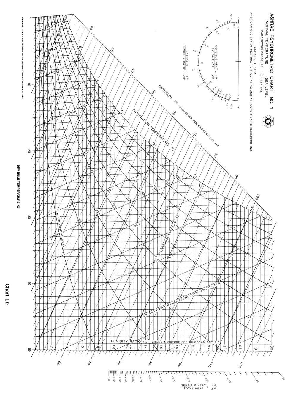
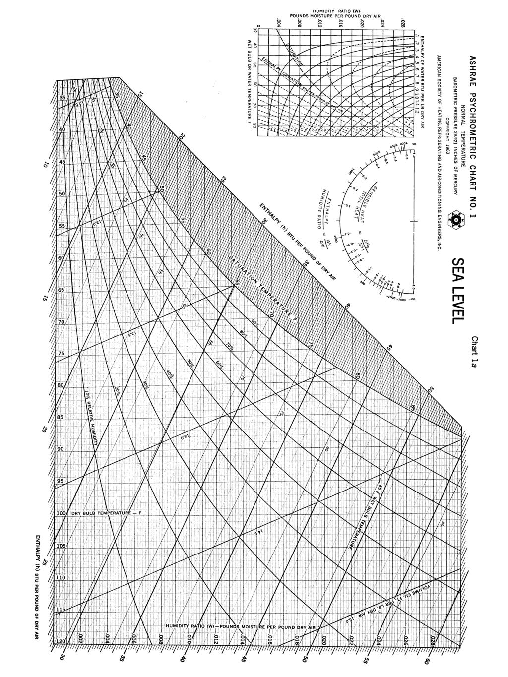
7 Insert thermistor (lab standard) into calibrator. Turn on the main power switch to the cooling tower, and the red LED readout for the thermocouple/temperature reading should become active. Adjust the thermocouple selector dial to read the output from T 1. At room temperature, and two temperature set-points (approximate 40 C and 50 C) take 10 measurements readings each from the thermistor (lab standard), cooling tower readout for channel 1 and DasyLAB software read out for T 1. Establish a spreadsheet for the 10 readings for all three sensors at each temperature, determine the average of each sensor reading and determine the accuracy of the cooling tower readout and the DASYLab readout relative to the thermistor standard. 5. Perform an accuracy check on the thermocouple in the tower using sensor T 1. Reinstall T 1 in the tower and turn the water flow rate adjustment knob (clockwise) to shut the water flow off. Switch on the main power so the pump will run, but no water will flow through the tower. Fully open the damper on the fan. Let the tower stabilize for 10 minutes. Operating the cooling tower with no water flow, only the fan with damper fully open, record the dry bulb thermocouple readings (T 1 and T 3 from the unit and DASYLab). Ideally, they should have the same readings; similarly the wet bulb thermocouples should the same values so record these as well. 6. Compare the mean values of T 1 and T 3 with the mean values of the T 2, T 4, T 5 and T 6. A difference in instrument readings, will this require a possible correction factor to bias the sensor readings? 7. Using the handheld temperature-relative humidity probe, carefully take readings at the inlet to the fan. Using the sling psychrometer (convert to degrees C if needed!), take wet and dry bulb measurements of the room. Record all data, and compare with the results of step 6 using a psychrometric chart given at the end of this handout. Put a copy of a chart in your log book indicating the three moist air states you have just determined (tower sensors at air inlet, handheld probe at air inlet, and room with sling psychrometer). 8. Connect the water system to allow for proper operation. Start the Bench Top Cooling Tower and observe the effects of orifice differential pressure, water flow rate and all the thermocouple readings. PROCEDURE (DAY 2) 1. Check wet bulb thermocouple reservoir wells for water (t 2 and t 4 ). Add if necessary. 2. The make-up tank should be at least half full before the starting the cooling tower. Use distilled water if fluid must be added to the system. Monitor and calculate the amount of water evaporated during all of the test operations of
8 the cooling tower. This can be done by measuring the cross-section of the make-up tower and finding the change in the water level. 3. Start the Bench Top Cooling Tower and allow to stabilize under the following suggested conditions: Air orifice differential pressure: 14 mm water Water flow rate: 30 gm/s Cooling load: 1.0 kw 4. Let the tower stabilize for 10 minutes. Go step 5 while waiting. 5. While you are waiting for the system to come to steady-state, there should be a power supply on the bench top, turned off with the black - lead unplugged. The power lead should read Pressure & Turbine Flow Meter Power 8.22 VDC. Make sure the red + side lead is plugged in, if it isn t. Turn the power supply on adjusting the voltage readout to as close to 8.22 V as you can. Observe the signal output leads (bundled with the power supply leads) from the pressure transducer and water turbine flow meter, and where they are connected to the data acquisition equipment. Be sure they are not touching each other or any other metal and that the connections appear sound. Now plug in the black - lead to the power supply. This should now provide power to the pressure transducer and turbine flow meter in the tower, and the power draw on the power supply should be about 0.01 A (10 ma). You can check the zero offset error on the transducer output by disconnecting the pressure tap tube connecting the high side pressure transducer port, which should be connected to the tap in the top/exit chamber of the cooling tower. Record this value from the DASYLab worksheet as you check it out in step 6. Then reconnect the pressure tap tubing. While continuing to wait for the system to come to steady-state proceed to step While you are waiting for the system to come to steady-state, familiarize yourself with the DASYLab worksheet created to acquire data from the cooling tower. In a past semester, two sensors were retrofitted to the tower by students as part of their final 58:080 project: a turbine flow meter (TFM) to measure water flow rate, and a piezo-resistive differential pressure transducer for measuring the mass of air flow through the tower. Observe that a counter is used on TFM to convert the wave pattern seen in the Y-t plot on the TFM output to a frequency. The frequency output has been calibrated as shown in Figure 2, and this calibration curve is applied in the DASYLab worksheet to output the water flow rate in gram/sec. The pressure transducer output has been calibrated as shown in Figure 3, and the calibration curve. The orifice at the top of the cooling tower (an example of an obstruction flow meter) has been calibrated by the manufacturer to measure mass flow rate of dry air as a function of differential pressure across the orifice and specific volume of the moist air mixture exiting the tower. This relationship is:
9 mass flow rateof dry air m air Porifice 1 where ΔP orifice is the orifice pressure difference in mm H 2 O, υ air is the specific volume of dry air (m 3 /kg), and ω out is the specific humidity of the air exiting the tower (kg/kg). 7. Record the six thermocouple values, and the inlet and exit air relative humidity and temperature using the handheld humidity probe. Note: each time you are told to record thermocouple values, record the digital readout from the unit, and the readout from the DASYLAB. Take thermocouple readings 3 times, in 2 minute intervals. 8. Before proceeding check the make up level of the water, and add water as needed to bring the level back to the level at the start of the cooling tower operation in step 2. Be sure to measure how much make up water you add. Increase the cooling load to 1.5kW. Let the tower stabilize for 10 minutes. Record the six thermocouple values, and the inlet and exit air relative humidity and temperature using the handheld humidity probe: 3 times, in 2 minute intervals. out 9. Before proceeding check the make up level of the water, and add water as needed to bring the level back to the level at the start of the cooling tower operation in step 2. Start the Bench Top Cooling Tower and allow to stabilize under the following suggested conditions: Air orifice differential: 6 mm water Water flow rate: 30 gm/s Cooling load: 1.0 kw 10. Let the tower stabilize for 10 minutes. Record the six thermocouple values, and the inlet and exit air relative humidity and temperature using the handheld humidity probe. Take thermocouple readings 3 times, in 2 minute intervals. 11. Before proceeding check the make up level of the water, and add water as needed to bring the level back to the level at the start of the cooling tower operation in step 2. Increase the cooling load to 1.5kW. Let the tower stabilize for 10 minutes. Record thermocouple values. Record the six thermocouple values, and the inlet and exit air relative humidity and temperature using the handheld humidity probe - 3 times, in 2 minute intervals.
10 ANALYSIS 1. Calculate average, precision and bias errors, and total error for the thermocouples. See the Appendix A Determining Bias and Precision Errors for a detailed procedure on these calculations. Essentially, the bias error is the difference between your standard and the mean of your measurements, and the precision error is the 95% confidence interval about your mean value. The total error is the root sum of the squares of both. 2. Using a psychrometric chart given at the end of this handout, determine the relative humidity in the room for each setting at which the unit was run using the wet and dry bulb inlet air temperatures (averaged). Compare with the handheld probe at each setting. Is the room becoming more humid as the testing progresses (systematic), or does it appear random? 3. Find the evaporation rate of the cooling tower at the different settings using your make up water measurements. Comment on the results, does the trend in the data make sense given the operating conditions used? 4. Calculate the effectiveness of the cooling tower by calculating the difference between the water exiting the cooling tower (T 6 ) and the wet bulb temperature of the air entering the cooling tower (T 2 ). This is known in cooling tower terminology as the approach temperature. Is it physically possible for the approach temperature (T6 T2) to be less than 0? 5. Compare and comment on the results between the cooling tower operating conditions. What test matrix of variables was used, which variables were held constant (or controlled) which did we vary? Remark on any other interesting tests that might be run, measurements which don t make sense, and any other engineering observations about the experiment.
11 Measured flow (g/s) APPENDIX.A FIGURES Figure 2 Calibration curve for the pressure transducer Mass Flow Calibration Curve Flow (g/s) = (TFM Output, Hz) y = x R 2 = Flow meter output (Hz) Figure 3 Calibration curve for the turbine flow meter added to the Experimental Engineering Lab s Cooling Tower
12
13
Bench Top Cooling Tower H893
 Bench Top Cooling Tower H893 Figure 1: H893 Shown with Column B (fitted) and Optional Column E Demonstrates all processes found in a full scale forced draught cooling tower Rapid stabilisation allows experimental
Exercise 2-4. Heat Exchangers (Optional Exercise) EXERCISE OBJECTIVE DISCUSSION OUTLINE. Description of a brazed plate heat exchanger DISCUSSION
 EXERCISE OBJECTIVE DISCUSSION OUTLINE. Description of a brazed plate heat exchanger DISCUSSION") Exercise 2-4 Heat Exchangers (Optional Exercise) EXERCISE OBJECTIVE In this exercise, you will become familiar with plate heat exchangers. You will set up a cooling and a heating loop passing through the
Exercise 2-4 Heat Exchangers (Optional Exercise) EXERCISE OBJECTIVE In this exercise, you will become familiar with plate heat exchangers. You will set up a cooling and a heating loop passing through the
3.4 Humidity. Types of instruments
 Practical Handbook of Tower Flux Observation (Ver..0) Chapter 3 3.4 Humidity Humidity is the amount of water vapor in the air, which is expressed by various indexes depending on the study objectives. These
A660 Air Conditioning Laboratory Unit
 A660 Air Conditioning Laboratory Unit Figure 1: A660 Base Unit shown with all options fitted High accuracy wet and dry bulb sensors before and after each process to determine air condition. All processes
AND AIR-CONDITIONING. Dr Ali Jawarneh Department of Mechanical Engineering Hashemite University
 Chapter 14 GAS VAPOR MIXTURES AND AIR-CONDITIONING Dr Ali Jawarneh Department of Mechanical Engineering Hashemite University 2 Objectives Differentiate between dry air and atmospheric air. Define and calculate
ME 410 MECHANICAL ENGINEERING SYSTEMS LABORATORY MASS & ENERGY BALANCES IN PSYCHROMETRIC PROCESSES EXPERIMENT 3
 ME 410 MECHANICAL ENGINEERING SYSTEMS LABORATORY MASS & ENERGY BALANCES IN PSYCHROMETRIC PROCESSES EXPERIMENT 3 1. OBJECTIVE The objective of this experiment is to observe four basic psychrometric processes
LEAKAGE MONITORING OF SEAL PLUG FOR INDIAN PRESSURIZED HEAVY WATER REACTOR BY PSYCHOMETRICS ANALYSIS METHOD
 Proceedings of the National Seminar & Exhibition on Non-Destructive Evaluation NDE 2011, December 8-10, 2011 LEAKAGE MONITORING OF SEAL PLUG FOR INDIAN PRESSURIZED HEAVY WATER REACTOR BY PSYCHOMETRICS
For an ideal gas mixture, Dalton s law states that the sum of the partial pressures of the individual components is equal to the total pressure.
 1 PSYCHROMETICS Psychrometry is the study of the characteristics of moist air. We will see soon that evaporation of moisture from the skin can have a significant impact on thermal comfort. The rate of
Technical college/ Baghdad 4th Year Week No. :- 11. The objectives of this lesson are to: Introduction:
 Refrigeration Systems Theoretical hours: 2 Practical hours: 2 Units: 6 COOLING TOWERS First 10 minutes: review the last lecture. Then explain the new lecture, solve an example. Last 10 minutes review the
Psychrometrics. Outline. Psychrometrics. What is psychrometrics? Psychrometrics in daily life and food industry Psychrometric chart
 Psychrometrics Outline What is psychrometrics? Psychrometrics in daily life and food industry Psychrometric chart Dry bulb temperature, wet bulb temperature, absolute humidity, relative humidity, specific
TMCI Padovan Evaporators
 TMCI Padovan Evaporators Evaporators Our range includes 4 types of evaporators: Forced Circulation Falling Film Evaporators Plates Thin Film Concentration systems Evaporator choosing criteria: product
THERMODYNAMICS STEAM P7690 AND STEAM BENCHES CUSSONS TECHNOLOGY LABORATORY RECOMMENDATION
 cussons TECHNOLOGY THERMODYNAMICS STEAM P7690 AND STEAM BENCHES CUSSONS TECHNOLOGY LABORATORY RECOMMENDATION Thermodynamics is a branch of physical science concerned with the inter-relationship and inter-conversion
Air & Water Heat Pump R832
 Figure 1 : R832 P.A. Hilton Ltd Air & Water Heat Pump R832 Vapour Compression Heat Pump that allows Performance Investigation from both Air and Water Sources. Rapid Stabilisation enables detailed Investigation
How about Savings in Time, Money, Energy and Longer Life?
 Chapter 17: The Value of Maintaining Evaporative Cooling Equipment 97 The Value 17 of Maintaining Evaporative Cooling Equipment 1. Cooling Tower Maintenance and Upgrades... What s in it for You? How about
Evaporation studied on a duplicated vessel, pilot scale evaporator equipped with a heat pump
 Evaporation studied on a duplicated vessel, pilot scale evaporator equipped with a heat pump 1. Theory In a steam-heated concentrator temperature changes with the location in the vessel because of the
CHAPTER 2 EXPERIMENTAL APPARATUS AND PROCEDURES
 CHAPTER 2 EXPERIMENTAL APPARATUS AND PROCEDURES The experimental system established in the present study to investigate the transient flow boiling heat transfer and associated bubble characteristics of
Chapter 14, Problem 27.
 Chapter 14, Problem 27. A house contains air at 25 C and 65 percent relative humidity. Will any moisture condense on the inner surfaces of the windows when the temperature of the window drops to 10 C?
Instruction Manual DIGITAL MANIFOLD FOR HVAC/R SYSTEMS
 English Instruction Manual DIGITAL MANIFOLD FOR HVAC/R SYSTEMS 99 Washington Street Melrose, MA 02176 Phone 781-665-1400 Toll Free 1-800-517-8431 Visit us at www.testequipmentdepot.com Instruction Manual
READ AND SAVE THESE INSTRUCTIONS OWNER S MANUAL FOR BYPASS AND FAN POWERED HUMIDIFIERS. Small or Large Bypass 12 Water Saver Bypass 13 Fan Powered 14
 READ AND SAVE THESE INSTRUCTIONS OWNER S MANUAL FOR BYPASS AND FAN POWERED HUMIDIFIERS Type Installed: Maintenance page: Small or Large Bypass 12 Water Saver Bypass 13 Fan Powered 14 Includes Safety, Operating
Mechanical Heat Pump R515
 P.A.Hilton Ltd Mechanical Heat Pump R515 Above: R515 shown fitted with standard wattmeter Stabilises in minutes allowing many tests to be conducted in a typical laboratory period. Allows a complete refrigerant
ME 410 MECHA ICAL E GI EERI G SYSTEMS LABORATORY
 ME 410 MECHA ICAL E GI EERI G SYSTEMS LABORATORY MASS & E ERGY BALA CES I PSYCHROMETRIC PROCESSES EXPERIME T 3 1. OBJECTIVE The object of this experiment is to observe four basic psychrometric processes
Overall Heat Transfer Coefficient for Double-Pipe Heat Exchanger
 Overall Heat Transfer Coefficient for Double-Pipe Heat Exchanger Pre-laboratory Assignment Review the following: concept of the double-pipe heat exchanger, the overall heat transfer coefficient, logarithmic
Alfa Laval Wet Surface Air Coolers (WSAC ) FAQs
 FAQs") Alfa Laval Wet Surface Air Coolers (WSAC ) FAQs Q: How is the WSAC a closed-loop cooling system? A: The WSAC is a closed-loop cooling system because the process loop being cooled is inside the tube bundles
Alfa Laval Wet Surface Air Coolers (WSAC ) FAQs Q: How is the WSAC a closed-loop cooling system? A: The WSAC is a closed-loop cooling system because the process loop being cooled is inside the tube bundles
In order to be useful, many substances must be available in pure form.
 DISTILLATION COLUMN INTRODUCTION In order to be useful, many substances must be available in pure form. In the real world substances are seldom found or produced pure, they are frequently found mixed together
Introduction Portable Meters Transmitter Probes RELATIVE HUMIDITY
 S E C T I O N 10 C O N T E N T S N A V I G A T I O N Introduction.................... 10.2 Portable Meters................. 10.3 Transmitter..................... 10.9 Probes......................... 10.10
Appendix A. Glossary of Common Terms
 Glossary of Common Terms Glossary of Common Terms Absorption chiller A refrigeration machine using heat as the power input to generate chilled water. Adjustable speed drive A means of changing the speed
HVAC (Heating, Ventilating, and Air Conditioning)
") HVAC (Heating, Ventilating, and Air Conditioning) Gas vapor Mixtures The term vapor implies a gaseous state that is close to the saturation region of the substance, raising the possibility of condensation
HVAC (Heating, Ventilating, and Air Conditioning) Gas vapor Mixtures The term vapor implies a gaseous state that is close to the saturation region of the substance, raising the possibility of condensation
Scientific Principals and Analytical Model. Charcoal Cooler. Lisa Crofoot MECH 425, Queens University
 Scientific Principals and Analytical Model Charcoal Cooler Lisa Crofoot MECH 425, Queens University 1.0 Scientific Principles Evaporative cooling is based on the principle that water requires heat energy
Performance Rating of Commercial and Industrial Humidifiers
 AHRI Standard 641 (SI) 2017 Standard for Performance Rating of Commercial and Industrial Humidifiers IMPORTANT SAFETY DISCLAIMER AHRI does not set safety standards and does not certify or guarantee the
SBS5311 HVACR II Experiment 2: Analysis of the Combined Rankine and Vapour Compression Cycle
 Introduction SBS5311 HVACR II http://ibse.hk/sbs5311/ Experiment 2: Analysis of the Combined Rankine and Vapour Compression Cycle The Rankine cycle is an idealized thermodynamic cycle of a heat engine
Quality Assurance/ Quality Control. Topic 4 - Audio 46. Key Points
 Topic 4 - Audio 46 Key Points : Measures taken to increase confidence in results. Quality Assurance: Program that assures that measures are being done and in a timely manner. Precision: How close measurements
Performance of R-22, R-407C and R-410A at Constant Cooling Capacity in a 10
 Purdue University Purdue e-pubs International Refrigeration and Air Conditioning Conference School of Mechanical Engineering 2000 Performance of R-22, R-407C and R-410A at Constant Cooling Capacity in
Eastern Mediterranean University Department of Mechanical Engineering Laboratory Handout
 Eastern Mediterranean University Department of Mechanical Engineering Laboratory Handout COURSE: HEAT TRANSFER (MENG 345) Semester: 2017-2018 Fall Name of Experiment: Steady State Conduction Through a
LAB EQUIPMENT DETAILS
 DEPARTMENT OF MECHANICAL ENGINEERING LAB EQUIPMENT DETAILS S. N o Name of the Equipment Manufacturer Equipment Photo Description Applications Cost of the Equipment 1 Guarded plate The consists of main
Development of a Psychrometric Test Chamber. Michael J. Swedish. Associate Professor Mechanical Engineering Department Milwaukee School of Engineering
 Session 2633 Development of a Psychrometric Test Chamber Michael J. Swedish Associate Professor Mechanical Engineering Department Milwaukee School of Engineering Acknowledgments The design of the Psychrometric
Available online Journal of Scientific and Engineering Research, 2017, 4(10): Research Article
: Research Article") Available online www.jsaer.com, 2017, 4(10):305-311 Research Article ISSN: 2394-2630 CODEN(USA): JSERBR Low Cost Humidity/Temperature Calibration System Yasser A. Abdelaziz 1 Central Laboratories Department,
Available online www.jsaer.com, 2017, 4(10):305-311 Research Article ISSN: 2394-2630 CODEN(USA): JSERBR Low Cost Humidity/Temperature Calibration System Yasser A. Abdelaziz 1 Central Laboratories Department,
Refrigeration Cycle Demonstration Unit R634
 Refrigeration Cycle Demonstration Unit R634 Figure 1: R634 Unit shown with R634A and R634B fitted Ozone friendly, low pressure, non-toxic working fluid allows evaporation and condensation to be safely
Heat Exchanger. The purpose may be either to remove heat from a fluid or to add heat to a fluid.
 HEAT EXCHANGERS Heat Exchanger Heat exchanger is an apparatus or an equipment in which the process of heating or cooling occurs. The heat is transferred from one fluid being heated to another fluid being
cussons Refrigeration Assembly Range TECHNOLOGY REFRIGERATION AND AIR CONDITIONING CUSSONS TECHNOLOGY LABORATORY RECOMMENDATION
 REFRIGERATION AND AIR CONDITIONING CUSSONS LABORATORY RECOMMENDATION Cussons Refrigeration laboratories are offered to provide teaching to a range of different skill levels. In all the laboratories teaching
Refrigeration Cycle Demonstration Unit R633
 Refrigeration Cycle Demonstration Unit R633 Figure 1: R633 Unit Ozone friendly, low pressure, non-toxic working fluid allows evaporation and condensation to be seen in glass cylinders. A Bench top unit
MECHANICAL ENGINEERING ME.2017 FUNDAMENTAL OF REFRIGERATION AND AIR CONDITIONING. Sample Questions and Answers
 MECHANICAL ENGINEERING ME.2017 FUNDAMENTAL OF REFRIGERATION AND AIR CONDITIONING Sample Questions and Answers CHAPTER 5 EVAPORATORS 1. What is Evaporator? Classify the various types of evaporator. Evaporator
Drop-in Testing of Next-Generation R134a Alternates in a Commercial Bottle Cooler/Freezer
 Purdue University Purdue e-pubs International Refrigeration and Air Conditioning Conference School of Mechanical Engineering 2012 Drop-in Testing of Next-Generation R134a Alternates in a Commercial Bottle
2. HEAT EXCHANGERS MESA
 1. INTRODUCTION Multiport minichannel and microchannel aluminium tubes are becoming more popular as components in heat exchangers. These heat exchangers are used in various industrial applications and
What is Cooling S.Sen
 What is Cooling Tower @ S.Sen Gear Box Stack Shaft Fan Blade Motor Fill Theory of Cooling Towers Cooling towers fall into two main sub-divisions: natural draft and mechanical draft. Natural draft designs
Use this Construction/HVAC Glossary to answer the questions below.
 www.garyklinka.com Page 1 of 21 Instructions: 1. Print these pages. 2. Circle the correct answers and transfer to the answer sheet on the second last page. 3. Page down to the last page for the verification
Wet Bulb Thermo-Hygrometer Datalogger
 USER GUIDE Wet Bulb Thermo-Hygrometer Datalogger Plus Dew Point Temperature Model WB200 Introduction Thank you for selecting the Extech Instruments WB200 Thermo-Hygrometer Datalogger with Dew Point and
TECHNICAL SPECIFICATIONS - CW-80T-TWIN USA & MEXICO
 GENERAL Climate Wizard coolers operate with a high ratio of energy efficiency and deliver cool fresh air at extremely low energy cost. The CW-80T-TWIN is characterized by having no additional moisture
P.A. Hilton Ltd. Figure 2: HC655A Optional Computer Linking Upgrade
 Boiling Heat Transfer Unit H655 Figure 1: H655 Three Modes of Pool Boiling Observed Easily. Allows Safe Investigation into the Normally Dangerous condition of Film Boiling. Safe and Suitable For Unsupervised
Model 5190-F Temperature/Humidity Probe
 Model 5190-F Temperature/Humidity Probe FAA APPROVED ECP234 2017 Mar 13 NOT FAA APPROVED User s Manual Rev. C All Weather Inc. 1165 National Drive Sacramento, CA 95834 USA 800.824.5873 www.allweatherinc.com
Summary of Comments (Washington Revisions November 7, 2000) Update November 27, 2000
 Update November 27, 2000") SAE Alternate Refrigerant Cooperative Research Program Summary of Comments (Washington Revisions November 7, 2000) Update November 27, 2000 To: Alternate Refrigerant Task Force Members From: Ward Atkinson
SAE Alternate Refrigerant Cooperative Research Program Summary of Comments (Washington Revisions November 7, 2000) Update November 27, 2000 To: Alternate Refrigerant Task Force Members From: Ward Atkinson
CHAPTER 5 CONDENSER AND EVAPORATIVE COOLING TOWER
 CHAPTER 5 CONDENSER AND EVAPORATIVE COOLING TOWER 5.1. Condenser... 2 5.2. Evaporative Cooling Tower... 2 5.2.1. Major Components...3 Chapter 5-1 5.1. Condenser Condenser is a shell-and-tube heat exchanger.
Model 5190-E Temperature/Humidity Probe
 Model 5190-E Temperature/Humidity Probe User s Manual Rev. D All Weather Inc. 1165 National Drive Sacramento, CA 95834 USA 800.824.5873 www.allweatherinc.com Copyright 2010, All Weather, Inc. All Rights
PREDICTION OF THE PRESSURE DROP OF CO 2 IN AN EVAPORATOR USED FOR AIR COOLING ABSTRACT 1. INTRODUCTION 2. EXPERIMENTAL SET-UP AND PROCEDURE
 PREDICTION OF THE PRESSURE DROP OF CO 2 IN AN EVAPORATOR USED FOR AIR COOLING M. POIRIER, D. GIGUÈRE, Z. AIDOUN, M. OUZZANE Natural Resources Canada, CANMET Energy Technology Centre-Varennes 1615, Lionel
Activity Watering and Plant Growth
 Activity Watering and Plant Growth Students will design and carry out an experiment to determine how altering watering conditions (temperature, amount, size of droplet, time of day, mulching, type of soil,
What is a Closed circuit Cooling Tower (CCT)?
?") What is a Closed circuit Cooling Tower (CCT)? Closed circuit Cooling Towers are hybrids that pass the working fluids through a tube bundle, upon which clean water is sprayer and a faninduced draft applied.
What is a Closed circuit Cooling Tower (CCT)? Closed circuit Cooling Towers are hybrids that pass the working fluids through a tube bundle, upon which clean water is sprayer and a faninduced draft applied.
Gas Plant Training Module 4 TEG Dehydration Systems
 Module 4 TEG Dehydration Systems Table of Contents Introduction...2 Objectives...2 Glycol Dehydration...3 Dehydration System Process Control...4 Contactor C301...6 Glycol Regenerator...7 Flash Separator
MECHANICAL ENGINEERING THERMAL AND FLUID SYSTEMS STUDY PROBLEMS
 MECHANICAL ENGINEERING THERMAL AND FLUID SYSTEMS STUDY PROBLEMS MASS BALANCES, PSYCHROMETRICS & HVAC 1 Copyright 2018. All rights reserved. How to use this book The exam specifications in effect since
Effects of Flash and Vapor Injection on the Air-to- Air Heat Pump System
 Purdue University Purdue e-pubs International Refrigeration and Air Conditioning Conference School of Mechanical Engineering 2010 Effects of Flash and Vapor Injection on the Air-to- Air Heat Pump System
Hunting Phenomena Of Automotive Air Conditioning Systems With Variable Displacement Compressor
 Purdue University Purdue e-pubs International Refrigeration and Air Conditioning Conference School of Mechanical Engineering 22 Hunting Phenomena Of Automotive Air Conditioning Systems With Variable Displacement
Shell-and-Tube Heat Exchanger (Four Passes) - Optional
 - Optional") Exercise 2-4 Shell-and-Tube Exchanger (Four Passes) - Optional EXERCISE OBJECTIVE When you have completed this exercise, you will be familiar with the design and particularities of the four-pass shell
Exercise 2-4 Shell-and-Tube Exchanger (Four Passes) - Optional EXERCISE OBJECTIVE When you have completed this exercise, you will be familiar with the design and particularities of the four-pass shell
Design and Research of the Digital VRV Multi- Connected Units With Three Pipes Type Heat Recovery System
 Purdue University Purdue e-pubs International Refrigeration and Air Conditioning Conference School of Mechanical Engineering 2006 Design and Research of the Digital VRV Multi- Connected Units With Three
Davis Soil Moisture and Temperature Station Protocol
 Davis Soil Moisture and Temperature Station Protocol Purpose To log soil data using a Davis soil moisture and temperature station Overview Soil moisture and temperature sensors are installed at multiple
Hot Water Making Potential Using of a Conventional Air- Conditioner as an Air-Water Heat Pump
 Available online at www.sciencedirect.com Procedia Engineering 8 (2011) 165 170 2 nd International Science, Social-Science, Engineering and Energy Conference 2010: Engineering Science and Management Hot
HERMS (Heat Exchanger Recirculating Mash System) Controller
 Controller") HERMS (Heat Exchanger Recirculating Mash System) Controller Your new HERMS controller Thanks for buying your controller from us!!! Your controller is based on two MYPIN TA4 series PID controllers. Unlike
HERMS (Heat Exchanger Recirculating Mash System) Controller Your new HERMS controller Thanks for buying your controller from us!!! Your controller is based on two MYPIN TA4 series PID controllers. Unlike
TECHNICAL SPECIFICATIONS - CW-80T AUSTRALIAN, EUROPEAN, SOUTH AFRICAN & UK
 GENERAL Climate Wizard coolers operate with a high ratio of energy efficiency and deliver cool fresh air at extremely low energy cost. The CW-80T is characterized by having no additional moisture added
Celebrating over 30 years of excellence in manufacturing ultrasonic cleaning equipment, electropolishing equipment and associated chemistries
 Instructions for Model E1002 Ultrasonic Washer Introduction The Model E1002 ultrasonic washer is equipped to run timed cycles of clean, rinse and dry. The unit is housed in a 304 stainless steel cabinet.
Institute of Aeronautical Engineering (Autonomous) Dundigal, Hyderabad B.Tech (III II SEM) MECHANICAL ENGINEERING
 Dundigal, Hyderabad B.Tech (III II SEM) MECHANICAL ENGINEERING") Institute of Aeronautical Engineering (Autonomous) Dundigal, Hyderabad- 500 043 B.Tech (III II SEM) MECHANICAL ENGINEERING REFRIGERATION AND AIR CONDITIONING Prepared by, Dr. CH V K N S N Moorthy, Professor
Institute of Aeronautical Engineering (Autonomous) Dundigal, Hyderabad- 500 043 B.Tech (III II SEM) MECHANICAL ENGINEERING REFRIGERATION AND AIR CONDITIONING Prepared by, Dr. CH V K N S N Moorthy, Professor
ZERO AIR GENERATOR MODEL 7000 INSTRUCTION MANUAL
 ZERO AIR GENERATOR MODEL 7000 INSTRUCTION MANUAL UNPACKING Connect the intake filter to the Air In port as shown below. Use Teflon tape on filter thread if not supplied on the fitting. POWER The ZAG is
MODULE 6 HUMIDIFICATION AND AIR CONDITIONING
 MODULE 6 HUMIDIFICATION AND AIR CONDITIONING LECTURE NO. 3 6.3 Humidification and dehumidification operations and design calculations Humidification operations: In this operation, water transfers from
User Manual. For use with model CS-10A/CS-11A solar ventilation system controllers
 TM User Manual For use with model CS-10A/CS-11A solar ventilation system controllers Breeze Mate Solar Ventilation System Thank you for your purchase of the Breeze Mate solar ventilation system by Attic
Experimental Study on Match for Indoor and Outdoor Heat Exchanger of Residential Airconditioner
 Purdue University Purdue e-pubs International Refrigeration and Air Conditioning Conference School of Mechanical Engineering 2014 Experimental Study on Match for Indoor and Outdoor Heat Exchanger of Residential
Chapter 14 GAS VAPOR MIXTURES AND AIR-CONDITIONING
 Thermodynamics: An Engineering Approach, 6 th Edition Yunus A. Cengel, Michael A. Boles McGraw-Hill, 2008 Chapter 14 GAS VAPOR MIXTURES AND AIR-CONDITIONING Mehmet Kanoglu Copyright The McGraw-Hill Companies,
ME Mechanical Engineering Systems Laboratory. Experiment 3 - Mass and Energy Balances in Psychrometric Processes
 ME 410 - Mechanical Engineering Systems Laboratory Experiment 3 - Mass and Energy Balances in Psychrometric Processes Assist.Prof.Dr. Özgür BAYER, A-123 AIR-CONDITIONING (A/C) Goal: Control temperature
All rights reserved, Armando B. Corripio, PhD, PE, Solid Dryer Design Introduction Continuous Dryer Design...
 Solid Dryer Design All rights reserved, Armando B. Corripio, PhD, PE, 2014 Contents Solid Dryer Design... 1 Introduction... 2 1. Continuous Dryer Design... 3 1.1 Mass Balances... 4 1.2 Temperature Profiles...
Aprilaire Dehumidifier Troubleshooting Manual Models 1830, 1850, 1870
 Aprilaire Dehumidifier Troubleshooting Manual Models 1830, 1850, 1870 Table of Contents Troubleshooting Diagnostic Codes... 2 E1... 2 E2, E3... 3 E4.4 E5, E6... 7 E7, E8... 8 E9.9 Verifying Capacity...
Air Conditioning Clinic. Absorption Water Chillers One of the Equipment Series TRG-TRC011-EN
 Air Conditioning Clinic Absorption Water Chillers One of the Equipment Series TRG-TRC011-EN Absorption Water Chillers One of the Equipment Series A publication of The Trane Company Worldwide Applied Systems
Advance Optima Module Magnos 17
 Advance Optima Module Magnos 17 Service Manual 43/24-1002-0 EN Table of Contents Page Chapter 1: Description of functions 1-1 Chapter 2: Module variants and components 2-1 Chapter 3: Analyzer variants
THERMAPHASE INSTALLATION AND OPERATING INSTRUCTIONS
 Page 1 of 10 THERMAPHASE INSTALLATION AND OPERATING INSTRUCTIONS Purpose of Manual The purpose of this manual is to provide operating, servicing and repair instructions for the Summit standard models ThermaPhase
TECHNICAL SPECIFICATIONS - CW-80T-TWIN AUSTRALIAN, EUROPEAN, SOUTH AFRICAN & UK
 GENERAL Climate Wizard coolers operate with a high ratio of energy efficiency and deliver cool fresh air at extremely low energy cost. The CW-80T-TWIN is characterized by having no additional moisture
Vapour Jet Refrigerator / Heat Pump R853
 Vapour Jet Refrigerator / Heat Pump R853 Enables demonstration and investigation of the combined Rankine and Vapour Compression Cycle Is an example of a refrigerator or heat pump driven by a Heat Input
Understanding Process Vacuum for Process Improvement
 Understanding Process Vacuum for Process Improvement Through this article we wish to give practical tips to boost process capacity, increase product quality and reduce cycle time in batch or continuous
EXPERIMENTAL STUDY OF CENTRIFUGAL HUMIDIFIER FITTED IN AN INDUSTRIAL SHED LOCATED IN TROPICAL CLIMATES
 THERMAL SCIENCE, Year 2011, Vol. 15, No. 2, pp. 467-475 467 EXPERIMENTAL STUDY OF CENTRIFUGAL HUMIDIFIER FITTED IN AN INDUSTRIAL SHED LOCATED IN TROPICAL CLIMATES by Krishnasamy SENTHILKUMAR a* and Pss
Superheat charging curves for technicians
 This website requires certain cookies to work and uses other cookies to help you have the best experience. By visiting this website, certain cookies have already been set, which you may delete and block.
EST User Manual. (Please read this manual carefully before using)
") EST-1000 Handheld Intelligent Toxic Gas Detector User Manual (Please read this manual carefully before using) ENVIRONMENTAL SENSOR TECHNOLOGY CO.INC. Contents I. Product Overview...1 II. Product Description...1
EST-1000 Handheld Intelligent Toxic Gas Detector User Manual (Please read this manual carefully before using) ENVIRONMENTAL SENSOR TECHNOLOGY CO.INC. Contents I. Product Overview...1 II. Product Description...1
Chapter 8 Balances on Nonreactive Processes PSYCHROMETRIC CHART
 Chapter 8 Balances on Nonreactive Processes PSYCHROMETRIC CHART Figure 8.4-1 (p. 385) Terminologies Absolute Humidity % Relative Humidity Dew Point Humid Volume Dry-bulb Temperature Wet-bulb Temperature
SIR C.R.REDDY COLLEGE OF ENGINEERING, ELURU DEPARTMENT OF MECHANICAL ENGINEERING ETD-II. Model Short Answer Questions And Answers
 SIR C.R.REDDY COLLEGE OF ENGINEERING, ELURU DEPARTMENT OF MECHANICAL ENGINEERING ETD-II Model Short Answer Questions And Answers VAPOUR POWER CYCLES 1. What are the methods to increase thermal efficiency
INSTRUCTION MANUAL 4-WAY BALL VALVE Digital Manifold
 LOW VAC INSTRUCTION MANUAL 4-WAY BALL VALVE Digital Manifold REF HIGH SPECIAL FEATURES Low battery indicator Displays 63 refrigerants Displays corresponding saturation, dew or bubble point temperature
THE PSYCHROMETRIC CALCULATOR By: Stanley F. Gallos, The Bastian-Blessing Company INTRODUCTION PROPERTIES OF THE RSES CALCULATOR
 Source Application Manual SAM Chapter 620-20 Section 03 THE PSYCHROMETRIC CALCULATOR By: Stanley F. Gallos, The Bastian-Blessing Company INTRODUCTION Problems involving changes in temperature, humidity,
Thermodynamics II Chapter 6 Mixtures & Psychrometry
 Thermodynamics II Chapter 6 Mixtures & Psychrometry Mohsin Mohd Sies Fakulti Kejuruteraan Mekanikal, Universiti Teknologi Malaysia Objectives Differentiate between dry air and atmospheric air. Define and
Combination unit to support instruction in Thermodunamics, Fluid Mechanics, and Heat Transfer
 Paper ID #6647 Combination unit to support instruction in Thermodunamics, Fluid Mechanics, and Heat Transfer Dr. Lin Lin, University of Southern Maine Dr. Lin joined Department of Engineering at University
Heat Recovery Units. Heat Recovery 1
 Heat Recovery Units Heat Recovery 1 Heat Recovery Unit Why? A heat recovery unit (HRU) can help make mechanical ventilation more cost effective by reclaiming energy from exhaust airflows. HRUs use air-to-air
PumpLab TM Operator s Manual
 PumpLab TM Operator s Manual PumpLab TM Centrifugal Flow/ Process Control System i PumpLab TM Main Features Clear View Flow Circuit Outlet Valve Data Display/Record Flow Meter Exit Pressure Sensor Computer
Air Conditioning Clinic
 Air Conditioning Clinic Psychrometry One of the Fundamental Series D C B A C B D A July 2012 TRG-TRC001-EN Psychrometry One of the Fundamental Series A publication of Trane Preface Psychrometry A Trane
R07. Answer any FIVE Questions All Questions carry equal marks *****
 Set No: 1 III B.Tech. II Semester Supplementary Examinations, April/May 2013 REFRIGERATION AND AIR CONDITIONING (Mechanical Engineering) Time: 3 Hours Max Marks: 80 Answer any FIVE Questions All Questions
IGCSE PHYSICS GRADE 11 TERM 1 ASSESSMENT BOOKLET
 PHYSICS IGCSE PHYSICS GRADE 11 TERM 1 ASSESSMENT BOOKLET 2013-2014 STS Page 1 of 44 PHYSICS PHYSI1101 ASSESSMENT TASK COVER PAGE Topic STS Performance Criteria Assessment event Date Time Thermal Physics
Enhancement of Round Tube and Flat Tube- Louver Fin Heat Exchanger Performance Using Deluge Water Cooling
 Purdue University Purdue e-pubs International Refrigeration and Air Conditioning Conference School of Mechanical Engineering 2012 Enhancement of Round Tube and Flat Tube- Louver Fin Heat Exchanger Performance
College of Technological Studies Department of Power & Refrigeration Technology. Course Contents
 College of Technological Studies Department of Power & Refrigeration Technology Course Contents Course Designation: Air Conditioning Control systems Course No. : 272 0463 Credit Hrs.: 3 Lecture Hrs.: 2
4th International Conference on Sensors, Measurement and Intelligent Materials (ICSMIM 2015)
") 4th International Conference on Sensors, Measurement and Intelligent Materials (ICSMIM 2015) Multi-stage Series Heat Pump Drying System with Dehumidification Simulation and Experiment Verification Chao
4th International Conference on Sensors, Measurement and Intelligent Materials (ICSMIM 2015) Multi-stage Series Heat Pump Drying System with Dehumidification Simulation and Experiment Verification Chao
Performance Investigation of Refrigerant Vapor- Injection Technique for Residential Heat Pump Systems
 Purdue University Purdue e-pubs International Refrigeration and Air Conditioning Conference School of Mechanical Engineering 2008 Performance Investigation of Refrigerant Vapor- Injection Technique for
Process Simulation and Optimization of Cryogenic Operations Using Multi-Stream Brazed Aluminum Exchangers
 Page 1 of 12 Process Simulation and Optimization of Cryogenic Operations Using Multi-Stream Brazed Aluminum Exchangers JOHN C. POLASEK, Bryan Research & Engineering, Inc., Bryan, Texas STEPHEN T. DONNELLY,