Design, Installation & Servicing Instructions
|
|
|
- Eustace Harris
- 6 years ago
- Views:
Transcription


1 Ecodan Air Source Heat Pump A complete package to provide hot water and heating in domestic housing from an air source heat pump Design, Installation & Servicing Instructions BoilerMate Model Numbers BMA 180 HP-DEM-A BMA 210 HP-DEM-A BMA 240 HP-DEM-A Ecodan Air Source Heat Pump Model Number PUHZ-W50VHA PUHZ-W85VHA PUHZ-W140VHA

2 CONTENTS ISSUE 8: Section Page Summary Checklist 3 BOILERMATE HP-DEM-A DESIGN Introduction 5 Technical Data 8 System Details 17 INSTALLATION Site Requirements 29 Installation 30 Wiring Diagram 32 Wiring Connections 34 Commissioning 36 SERVICING Servicing/Maintenance 38 Changing Components 38 Short Parts List 39 Fault Finding 40 MITSUBISHI ELECTRIC ECODAN AIR SOURCE HEAT PUMP Installation Manual 41 FERNOX BOILER BUDDY Installation Manual 49 Building Regulations and Benchmark Commissioning The Building Regulations (England & Wales) require that the installation of a heating appliance be notified to the relevant Local Authority Building Control Department. From 1st April 2005 this can be achieved via a Competent Person Self Certification Scheme as an option to notifying the Local Authority directly. Similar arrangements will follow for Scotland and will apply in Northern Ireland from 1st January 06. FERNOX ALPHI-11 Product Data 53 CORGI operates a Self Certification Scheme for gas heating appliances. These arrangements represent a change from the situation whereby compliance with the Building Regulations was accepted if the Benchmark Logbook was completed and this was then left on site with the customer). With the introduction of a self certification scheme, the Benchmark Logbook is being replaced by a similar document in the form of a commissioning check list and a service interval record is included with all gas appliance manuals. However, the relevant Benchmark Logbook is still being included with all Thermal Storage products and unvented cylinders. Gledhill fully supports the Benchmark aims to improve the standards of installation and commissioning of central heating systems in the UK and to encourage the regular servicing of all central heating systems to ensure safety and efficiency. Building Regulations require that the heating installation should comply with the manufacturer s instructions. It is therefore important that the commissioning check list is completed by the competent installer. This check list only applies to installations in dwellings or some related structures. This product is manufactured under an ISO 9001:2000 Quality System audited by BSI. Patents Pending. The Gledhill s first priority is to give a high quality service to our customers. Quality is built into every Gledhill product and we hope you get satisfactory service from Gledhill. If not please let us know. Page 2
3 KEY DIFFERENCES FROM CONVENTIONAL HEATING SYSTEMS Summary Checklist for Mitsubishi Ecodan and Gledhill BoilerMate A-Class HP Installation This checklist has been created to help you understand the differences from other types of heating systems that you will have installed. We suggest you use this checklist as a helpful summary of the main differences from conventional heating systems, but you will also need to understand and comply with all of the technical details contained within this document to ensure a successful installation. BoilerMate A-Class HP-DEM-A Is normally mounted in the airing cupboard internal to the property. As it is based on an unvented cylinder, suitable provision needs to be made for the P&T discharge pipework. A 32A electrical power supply with a local isolator is needed to allow the Switch emergency electrical back-up to operate. Primary System Circuit It is very important that the primary system is cleansed using a suitable cleansing agent such as Fernox F3 to ensure that any flux residues / installation debris is removed. The heat pump and external connecting pipework require protection against freezing. For this reason a combined anti-freeze and inhibitor product such as Fernox Alpha-11 must be used in the correct quantity. The Fernox Boiler Buddy should be fitted internally on the heat pump return to help protect the heat pump from any heating system contamination and provide an ongoing visual indication of the system water condition. Externally Mounted Temperature Sensor An externally mounted temperature sensor is provided as part of the equipment package. This should be mounted in a suitable location on a north facing wall external to the property. Radiator System Circuit As the heat pump generates lower temperatures than a conventional boiler the radiators should have been designed to suit the lower mean temperature. Normally this will need an increase of emmitor size, but this will depend on the design heat loss of the building. Underfloor Heating Circuit The BoilerMate contains a prefitted pump for the heating circuit(s). When using an underfloor heating circuit, the manifolds should be of the nonpumped type. The blending valve should be set at the design temperature of the underfloor circuit. Interconnection Between Ecodan and BoilerMate A-Class HP A four core signal cable is needed to be run between the internal BoilerMate and the external Ecodan. This cable is polarized and must be connected correctly. Room Thermostat A 2 channel digital programmer is fitted to the front of the BoilerMate A-Class HP appliance. A separate room thermostat will normally be required. SUMMARY CHECKLIST Page 3
4 KEY DIFFERENCES FROM CONVENTIONAL HEATING SYSTEMS Mitsubishi Ecodan Air Source Heat Pump Is to be mounted external to the property in a suitable location using the detail provided in the manual and with a minimum distance of 300mm from the nearest wall. Cold air is blown from the front of the unit - it should be positioned in a location where this will not cause a nuisance. It should be mounted on anti-vibration mounts using eg. TICO material. The anti-vibration flexible hoses supplied should be fitted to the flow /return pipework. Under some operating conditions, condensate water may be produced which will drain away from the unit. If this is likely to cause a problem (eg. due to freezing on a pathway), we suggest incorporating a 150mm wide by 50mm deep gravel filled channel as a soakaway, or a similar arrangement to suit the location. The external flow / return pipework needs to be insulated and waterproofed to prevent freezing using Armaflex grade O pipe insulation. For the PUHZ-W50 a 16amp MCB is required, the W85 model requires a 25amp MCB, and the W140 model requires a 40amp MCB. All models need to be fitted with a local external isolator fitted in accordance with IEE wiring regulations. Hard Water Considerations A factory fitted scale inhibitor can be provided and should be specified at the time of order for hardness levels above 200 and up to 300 ppm(mg/l). Where the water is very hard ie above 300 ppm (mg/l) an optional polyphosphate type inhibitor should be ordered and fitted separately by the installer. Special Considerations In Retrofit Situations The heat exchanger in the heat pump must be protected from particulate contaminates in the water circuit. When fitting in a retrofit situation the existing radiator circuit MUST be chemically cleaned and thoroughly flushed by a competent person before installation. Incoming Water Supply SUMMARY CHECKLIST As the performance of hot and cold water systems is totally reliant on the incoming mains cold water supply, check that the pressure will be a minimum of 2 bar at times of maximum simultaneous use and that the flow rate is a minimum of 30 litres/minute. (For optimum performance this will need to be 50 litres in larger properties.) Page 4

5 DESIGN The BoilerMate A-Class HP-DEM-A is designed to be sold as part of a package with the Mitsubishi Electric Ecodan air source heat pump. The combination of the BoilerMate A-Class HP-DEM-A and the Mitsubishi Electric Ecodan air source heat pump has been the subject of independent testing by BRE and a report is available on request. Any water distribution and central heating installation must comply with the relevant recommendation of the current version of the Regulations and British Standards listed below:- Building Regulations I.E.E. Requirements for Electrical Installations (BS7671) Water Regulations Manual Handling Operations Regulations British Standards BS6798, BS5449, BS5546, BS5440:1, BS5440:2, CP331:3, BS6700, BS7593 and BS7671. Health and Safety Document No 635 A competent person as stated in the Building Regulations must install the BoilerMate heating system. The manufacturer s notes must not be taken as overriding statutory obligations. The BoilerMate A-Class HP-DEM-A model is based on an Accolade unvented hot water storage appliance and therefore is covered by section G3 of the Building Regulations. Unless the installer is part of an approved competent installer scheme the installation is notifiable to Building Control prior to commencement. An annual inspection is recommended to ensure safe, long term operation. This appliance must only be used with suitable heat pumps and is not suitable for use with any uncontrolled energy source such as solid fuel/steam. It should not be installed where the annual inspection is likely to be neglected. BMA 180 HP-DEM-A The information in this manual is provided to assist generally in the selection of equipment. The responsibility for the selection and specification of the equipment must however remain that of the customer and any Designers or Consultants concerned with the design and installation. Please note: We do not therefore accept any responsibility for matters of design, selection or specification or for the effectiveness of an installation containing one of our products unless we have been specifically requested to do so. In the interest of continuously improving the BoilerMate range, Gledhill Building Products Ltd reserve the right to modify the product without notice, and in these circumstances this document, which is accurate at the time of printing, should be disregarded. It will however be updated as soon as possible after the change has occurred. Modifications must not be made to this appliance. If any components are replaced in the field, they must be obtained from Gledhill Spares to ensure continued safe operation and must not be tampered with. This applies particularly to the immersion heaters which incorporate a pre-set overheat thermostat. BMA 210/240 HP-DEM-A INTRODUCTION Page 5
6 DESIGN HWS expansion vessel(s) supplied separately with the appliance for fitting on site Manual air vent (MAV) Secondary HWS return connection Primary relief valve T&P relief valve S1/2 S7 Externally mounted temperature compensation sensor CH boost 3kW S4 CH zone valve System circulator P2 IV HW zone valve MAV S3 HWS boost 3kW HWS outlet Combination valve Heat pump Boiler Buddy HP (primary) circulator P1 S5 S6 Discharge pipe Discharge pipe Balanced CWS outlet MCWS inlet Automatic bypass valve (if required) Zone 1 CH system (radiators or underfloor) IV IV Sealed primary system expansion/filling components available as an optional extra BoilerMate 180 HP-DEM-A Figure 1.1 A BoilerMate A-Class HP-DEM-A is a floor standing packaged mains pressure unvented hot water appliance designed for use with the Mitsubishi Electric Ecodan air source heat pump. All models are factory fitted with all the necessary safety and control equipment for connecting to the domestic water systems, heat pump and the heating system as can be seen from figures 1.1, 1.2, 1.3 and 1.4. The appliance has been specifically designed to maximise the efficiency of the heat pump and use the energy to provide improved space heating and mains pressure hot water performance. The BoilerMate A-Class HP-DEM-A is supplied with an outside temperature compensation sensor which needs to be mounted externally and wired back to the connection terminals provided in the appliance. This will then automatically adjust the operation of both zone 1 and zone 2 heating circuits to take account of the external temperature and reduce the running costs. INTRODUCTION The built in controls monitor the demands for heat ensuring that the low cost energy from the heat pump is used whenever possible and top up from the conventional heat source is only initiated when the flow temperature from the heat pump is not sufficient to meet the demands. The controls are set to provide hot water priority, ie. if there is a demand at S3, any heating demands will be suspended until the store temperature reaches the point where S3 is satisfied. All models are designed to heat the domestic hot water indirectly up to the maximum temperature possible with the heat pump and then boost the temperature by means of a 3kW immersion heater up to the required set temperature. All models have connections for zone 1 central heating circuit, however the 210 and 240 models also have connections for zone 2 central heating circuit. This enables separate radiator and underfloor heating circuits to be provided, operating at different design temperatures if required. The most economical way of designing the heating systems is to utilise the temperature available from the heat pump itself. For this reason, underfloor/low temperature radiator systems should be chosen where possible. In these situations. Page 6
7 DESIGN HWS expansion vessel(s) supplied separately with the appliance for fitting on site Manual air vent (MAV) Secondary HWS return connection Primary relief valve T&P relief valve S1/2 S7 Externally mounted temperature compensation sensor CH boost 3kW S4 CH zone valve System circulator P2 IV HW zone valve MAV S3 HWS boost 3kW HWS outlet Combination valve Heat pump Boiler Buddy HP (primary) circulator P1 S5 S6 Discharge pipe Zone 2 CH circulator P3 Non return valve IV Discharge pipe Balanced CWS outlet MCWS inlet IV Automatic bypass valve (if required) Zone 1 CH system (radiators or underfloor) Sealed primary system expansion/filling components available as an optional extra IV IV BoilerMate 210/240 HP-DEM-A Zone 2 CH system (underfloor or other low temperature heating system) Figure 1.2 Once installed and commissioned, the integration of all the heat pump, domestic hot water and central heating functions will be automatically controlled by the PCB built into the BoilerMate A-Class HP-DEM-A appliance. However, the temperature of the central heating will need to be controlled by remote room thermostat(s)/thermostatic radiator valves. In the event the heat pump fails, both the domestic hot water and central heating (partial only) can be heated using the built in electric heaters. This manual emergency heating mode can be selected by pressing the button labelled switch on the appliance front panel for 5 seconds. Even in this mode the controls will give priority to the hot water. However, the appliance should only be operated in this mode for the short period of time required for the problem to be resolved. The BoilerMate A-Class HP-DEM-A is designed to be sold as part of a package with the Mitsubishi Electric Ecodan air source heat pump. The combination of the BoilerMate A-Class HP-DEM-A and the Mitsubishi Electric Ecodan air source heat pump has been the subject of independent testing by BRE and a report is available on request. To allow a visual indication of system water quality and to protect the waterways of the heat pump from contamination a Fernox Boiler Buddy is provided as part of the package. Scale Protection The Building Regulations L1A: New dwellings/ L1B: Existing dwellings and the requirements set out in the Domestic Heating Compliance Guide specify that where the mains water hardness exceeds 200ppm provision should be made to treat the feed water to water heaters and the hot water circuit of combination boilers to reduce the rate of accumulation of lime scale. To comply with this requirement the hardness of the mains water should be checked by the installer and if necessary the optional factory fitted in-line scale inhibitor should be specified at the time of order for hardness levels between 200 and 300 ppm (mg/l). Where the water is very hard ie 300ppm (mg/l) and above the optional polyphosphate type, inhibitor should be specified at the time of order. However, this will need to be fitted by the installer at a suitable point in the cold water supply to the appliance. INTRODUCTION Page 7
.")
8 DESIGN TECHNICAL DATA 13 (front) 6 4 7/ (10/11) Other Optional Equipment (mid) BoilerMate A-Class HP-DEM-A 180 model 32 (rear) /22 35 Figure 1.3 Hot and cold water manifolds for use with plastic pipework (Set 1 or 2). Electronic scale inhibitor for mains water services with hardness levels above 200ppm (mg/l) fitted in the appliance. Polyphosphate scale and corrosion inhibitor for mains water services with hardness levels above 300ppm (mg/l) for fitting on site by the installer. 180 model Factory Fitted/Supplied Components 1 Domestic mains cold water inlet connection - see notes on page 12 2 Balanced pressure cold water outlet connection 3 Combination inlet control valve - unvented store 4 Pressure relief (safety) valve - primary system 5 Expansion vessel connection - unvented store 5a Expansion vessel - unvented store - see notes on page 12 & Figure Pressure and temperature relief valve - unvented store 7 Tundish 8 S5 sensor - heat pump return 9 Expansion vessel connection - primary system (Heat pump and heating circuit) 10 Expansion vessel/gauge - primary system - see notes on page Temporary filling loop - primary system - see notes on page Drain valve 13 Manual air vents - primary systems 14 Central heating (Zone 1)/hot water systems circulator (P2) 15 D.H.W. zone valve (energy cut out) 16 Central heating zone valve (Zone 1) 17 Central heating flow connection (Zone 1) - Isolating valve 18 Central heating return connection (Zone 1) 19 Flow connection (from heat pump) 20 Heat pump system circulator (P1) 21 Return connection (to heat pump) 22 Discharge pipe connection 23 S6 sensor - heat pump flow 24 S4 sensor - central heating flow (+ boost) 25 Electrical temperature boost assembly - central heating (Zone 1 only) 26 S3 sensor - hot water boost 27 Primary system manifold 28 Electrical temperature boost (hot water only) 29 Flow to hot water coil - unvented system 30 Return from hot water coil - unvented store 31 Domestic hot water outlet connection 32 Secondary domestic hot water return connection 33 Electrical control panel/printed circuit boards and connection terminals 34 User control panel and 2 channel clock mm high installation base 37 S7 external temperature compensation sensor 38 Fernox Boiler Buddy in-line filter - see notes on page 49 Page 8
9 DESIGN 13 (front) 6 4 7/ (11) Other Optional Equipment 5 (mid) BoilerMate A-Class HP-DEM-A 210 & 240 models 32 (rear) /22 39 Figure 1.4 Hot and cold water manifolds for use with plastic pipework (Set 1 or 2). Electronic scale inhibitor for mains water services with hardness levels above 200ppm (mg/l) fitted in the appliance. Polyphosphate scale and corrosion inhibitor for mains water services with hardness levels above 300ppm (mg/l) for fitting on site by the installer. 210/240 models Factory Fitted/Supplied Components 1 Domestic mains cold water inlet connection - see notes on page 12 2 Balanced pressure cold water outlet connection 3 Combination inlet control valve - unvented store 4 Pressure relief (safety) valve - primary system 5 Expansion vessel connection - unvented store 5a Expansion vessel - unvented store - see notes on page 12 & Figure Pressure and temperature relief valve - unvented store 7 Tundish 8 S5 sensor - heat pump return 9 Not used on this model 10 Central heating return (Zone 2) connection - expansion vessel/gauge - primary system - see notes on page Temporary filling loop - primary system - see notes on page Drain valve 13 Manual air vents - primary systems 14 Central heating (Zone 1)/hot water systems circulator (P2) 15 D.H.W. zone valve (energy cut out) 16 Central heating zone valve (Zone 1) 17 Central heating flow connection (Zone 1) - Isolating valve 18 Central heating return connection (Zone 1) 19 Flow connection (from heat pump) 20 Heat pump system circulator (P1) 21 Return connection (to heat pump) 22 Discharge pipe connection 23 S6 sensor - heat pump flow 24 S4 sensor - central heating flow (+ boost) 25 Electrical temperature boost assembly - central heating (Zone 1 only) 26 S3 sensor - hot water boost 27 Primary system manifold 28 Electrical temperature boost (hot water only) 29 Flow to hot water coil - unvented system 30 Return from hot water coil - unvented store 31 Domestic hot water outlet connection 32 Secondary domestic hot water return connection 33 Electrical control panel/printed circuit boards and connection terminals 34 User control panel and 2 channel clock 35 Central heating circulator (P3)(Zone 2) 36 Central heating flow connection (Zone 2) 37 S7 external temperature compensation sensor 38 Fernox Boiler Buddy in-line filter - see notes on page mm high installation base 40 Non return valve TECHNICAL DATA Page 9
 Water out (flow) Water in (return) Figure 1.")
10 DESIGN Primary System Pipework Connections for BoilerMate A-Class HP-DEM-A 180 Model Only Please note: This is a diagramatic representation, all pipework should enter through base of appliance. All connections are 22mm. Zone 1 flow Either radiator or underfloor heating circuit Zone 1 return TECHNICAL DATA A B Ecodan (rear) Water out (flow) Water in (return) Figure 1.5 Page 10

11 DESIGN Primary System Pipework Connections for BoilerMate A-Class HP-DEM-A 210 & 240 Models Only Please note: This is a diagramatic representation, all pipework should enter through base of appliance. All connections are 28mm. Zone 1 flow Non return valve Zone 1 Either radiator or underfloor heating circuit Zone 1 return A B Ecodan (rear) Water out (flow) Water in (return) Zone 2 return Zone 2 flow Zone 2 Underfloor or other low temperature heating circuit Figure 1.6 TECHNICAL DATA Page 11
.")
12 DESIGN Notes: Item 5a is supplied separately with the appliance (see Figure 1.7 and Table 1.1 below for details), complete with a fixing bracket. Items 10 and 11 are available as an optional Primary Sealed System Kit at extra cost. If required, this should be ordered at the same time as the appliance (see Table 1.1 below for details). The expansion vessels are provided with a suitable fixing bracket. Item 38 is supplied separately with the air source heat pump package for fitting internally in the heat pump return as near as possible to the heat pump, fully in accordance with the manufacturers instructions included later in this manual. The appliance is available with the option of a factory fitted scale inhibitor, at extra cost. In this case the aerial is fitted on the 22mm cold inlet and the scale inhibitor PCB is fitted in the electrical panel/pcb area. 5a Figure 1.7 Primary and unvented store expansion vessel TECHNICAL DATA Table 1.1 Expansion Vessels Model Primary Expansion Vessel (Optional Extra) Unvented Store Expansion Vessel (Supplied) Capacity (l) Size-each (mm) LxDiam Capacity (l) Size-each (mm) LxDiam BMA 180 HP-DEM-A x x 270 BMA 210 HP-DEM-A x x 270 BMA 240 HP-DEM-A x x 290 The size of the primary system expansion vessel has been calculated using typical design criteria for the maximum recommended heating load shown in Table 1.2. However, the size should be checked and confirmed as being accurate by the system designer/installer. Page 12
13 DESIGN Table 1.2 Technical Data Model BMA 180 HP-DEM-A BMA 210 HP-DEM-A BMA 240 HP-DEM-A Nominal domestic hot water storage volume (litres) Overall app. dimensions (mm) (Height x Width x Depth) 1370 x 595 x x 595 x x 595 x 595 Minimum recommended cupboard dimensions (mm) (Height x Width x Depth) 1970 x 700 x 600 (1) 2200 x 700 x 600 (1) 2250 x 700 x 600 (1) Weight (kg) (Empty / Full) 87 / / / 329 Type: Varem 1 Off (2) Unvented store expansion vessel Total nominal volume (litres) Charge pressure (bar) 1.5 Heat pump circuit circulating pump P1 Grundfos UPS System circulating pump P2 (HW and Zone 1 CH) Grundfos UPS Circulating pump P3 (Zone 2 CH) Grundfos UPS HW circuit zone valve - type Honeywell V mm CH circuit zone valve - type Honeywell V mm Electrical data for BoilerMate HP-DEM-A Control & overheat safety thermostat temperature settings Supply: 230V AC, 50Hz rated at 6.5kW Main supply circuit breaker 32A type B Internal protection: Immersion heaters 2 x 16A MCBs (Type B) Internal protection: Control circuit 1 x 6A MCB (Type B) Internal protection: Heat pump L.V. control signal (12VDC signal) 1 x 100mA 20mm glass cartridge fuse (+ spare) HW boost immersion heater S1/S2 safety sensors (3) P & T valve CH boost immersion heater 90 0 C Control thermostat (5) : 65 0 C, Overheat thermostat (4) : 85 0 C Mains inlet pressure regulator 1.5 bar Control/relief valve pressure Expansion relief valve (CW) 3.0 bar set points Expansion relief valve (CH) 3.0 bar P & T valve 4.0 bar Maximum hot water flow rate Dwelling type Bedrooms Bathrooms En-suite kw, PUHZ-W50VHA 5kW Maximum design heating load 8.5 kw, PUHZ-W85VHA 8.5kW 14.0 kw, PUHZ-W140VHA 14kW Electrical backup for heating and hot water 6kW (1) The sizes shown allow for the unvented store expansion vessel to be fitted above the appliance in the case of the 180 and 210 models, but assume that the optional primary sealed system kit will be fitted elsewhere. The dimensions for the 240 model assume both the unvented store and primary expansion vessels will be fitted elsewhere due to the height of the appliance itself. Clear access 650 deep will be required in front of the whole of the appliance for future maintenance. (2) Supplied loose - To be fitted by installer in a suitably accessible location. (3) Temperature is automatically controlled by the controller sensors S1/S2. (4) Not adjustable - Manual reset type. (5) Temperature is automatically controlled by the controller sensor therefore should not be set lower than 65 0 C. TECHNICAL DATA Page 13
14 DESIGN Control Parameters and Sensor Default Temperature Settings These are shown later in this manual under Front Panel Controls. Model Selection Data General guidance is given in Table 1.2. When checking the suitability of the heat pump we recommend that the heat losses of the external building fabric plus half of the ventilation losses are directly compared to the Ecodan model heat pump output of 5kW, 8.5kW and 14kW. If design calculations are carried out in the normal way, using the method set out in BS5449. The Ecodan heat pump will cope with heating systems in which boiler sizes calculated in this way are rated at up to a maximum of 6kW, 12kW and 16kW. As the BoilerMate A-Class HP-DEM-A is a hot water storage appliance, we recommend that the model size of the appliance is chosen by calculating the hot water volume in the normal way using the criteria set out in BS 6700 / NHBC for storage appliances. Electricity Supply One mains supply rated at 32A, 230V~, 50Hz is required for the internal BoilerMate HP-DEM-A. Minimum external fuse rating and the main supply cable ratings are given in Table 1.2 Technical Data section of this manual. This appliance MUST BE EARTHED. All external wiring to the appliance must be in accordance with the latest I.E.E. Wiring Regulation, and any local regulations which may apply. The appliance shall be supplied from a suitably rated double pole isolator with a contact separation of at least 3mm in both poles. This must be suitably labelled, provide complete electrical isolation and be within 1 metre of the BoilerMate A-Class HP-DEM-A Unit. In the event of an electrical fault after installation of the appliance, preliminary electrical checks must be carried out i.e. Earth Continuity, Short Circuit, Polarity, and Resistance to Earth. Appliance Location The BoilerMate A-Class HP-DEM-A appliance must be installed on a flat surface which is capable of supporting the weight of the appliance and any other ancillary equipment. (The full weight must be used, see table 1.2 on page 13). The appliance sizes and the minimum cupboard dimensions are shown in Table 1.2. A minimum of 600mm is required in front of the appliance for maintenance purposes. (See figures 1.3 and 1.4 on pages 8 and 9). The appliance is designed to be installed on the timber plinth supplied with the appliance. TECHNICAL DATA Details of the various electrical and pipework connections required are shown in Figures 1.3 and 1.4. Page 14
15 DESIGN 180 Model Connection Details/Dimensions 180 Model Connection Details/Dimensions - Top 595 Diagram opposite show the connection details and dimensions for the BoilerMate A-Class HP- DEM-A 180 model. 575 (595 including the door/clock) DHWS Secondary Return DHWS Expansion Primary System Vent The BoilerMate A-Class HP-DEM-A units are supplied on an installation base to allow the pipe runs to connect to the appliance from any direction. It is easier if all pipes protrude vertically in the cut out area shown. Compression or push fit connections can be used. All pipe positions are approximate and subject to a tolerance of +/-20mm in any direction. Note: All dimensions are shown in mm and are to the centre line of pipework/gland Model Connection Details/Dimensions - Bottom (595 including the door/clock) Heat Pump Return P&T Relief Valve Discharge Sealed Primary Exp. Vessel Heating Flow (Zone 1) Heating Return (Zone 1) 390 Expansion Relief Valve Discharge Heat Pump Flow Hot To Taps Cold In Figure 1.9 TECHNICAL DATA Page 15
16 DESIGN 210/240 Model Connection Details/Dimensions 210/240 Models Connection Details/Dimensions - Top 595 Diagram opposite show the connection details and dimensions for the BoilerMate A-Class HP- DEM-A 210/240 models. 575 (595 including the door/clock) DHWS Secondary Return DHWS Expansion Primary System Vent The BoilerMate A-Class HP-DEM-A units are supplied on an installation base to allow the pipe runs to connect to the appliance from any direction. It is easier if all pipes protrude vertically in the cut out area shown. Compression or push fit connections can be used. All pipe positions are approximate and subject to a tolerance of +/-20mm in any direction. Note: All dimensions are shown in mm and are to the centre line of pipework/gland /240 Models Connection Details/Dimensions - Bottom (595 including the door/clock) Heat Pump Return P&T Relief Valve Discharge Heating Return (Zone 2) Heating Flow (Zone 1) Heating Return (Zone 1) Heat Pump Flow Expansion Relief Valve Discharge Heating Flow (Zone 2) Hot To Taps Cold In TECHNICAL DATA Figure 1.10 Page 16
17 DESIGN Hot and Cold Water System All recommendations with regard to pipe work systems in this manual are generally based on the use of BS/EN Standard copper pipework and fittings. However a plastic pipework system can be used in place of copper internally as long as the chosen system is recommended by the manufacturer for use in cold and hot water systems and is designed and installed fully in accordance with their recommendations. If the incoming mains pressure exceeds 6 bar at any time in a 24 hour cycle then a pressure regulating valve set at 3.5 bar should be fitted downstream of the stop tap where the cold supply enters the property. Equipment used in the system should be suitable for a working pressure of up to 5 bar. It is also important that if an alternative pipework material/system is chosen, the manufacturer confirms that the design criteria for the new system is at least equivalent to the use of BS/EN Standard copper pipework and fittings or larger pipe sizes are considered. In these appliances the mains inlet pressure regulating valve is set to 1.5 bar and this setting MUST NOT be adjusted. Therefore the flow rate from the appliance depends upon the resistance of the hot water supply network, capacity of the incoming mains and the characteristics of the pressure regulating valve Mains Cold Water Supply The BoilerMate A-Class HP-DEM-A appliance is designed to be connected directly to the mains. The combination inlet valve incorporates the required check valve. The hot water flow rate achievable is directly related to the adequacy of the cold water mains serving the property. For this reason the cold water supply to the dwelling must be capable of providing for those services which could be required simultaneously and this maximum demand should be calculated. Also if a water meter is fitted its nominal rating should match the anticipated maximum simultaneous hot and cold water demand calculated in accordance with BS This could be 60 litres per minute in some properties. 30 litres per minute is the minimum flow rate which is recommended for an adequate mains pressure system to any property. The Building Regulations L1A: New dwellings/l1b: Existing dwellings and the requirements set out in the Domestic Heating Compliance Guide specify that where the mains water hardness exceeds 200ppm provision should be made to treat the feed water to water heaters and the hot water circuit of combination boilers to reduce the rate of accumulation of lime scale. To comply with this requirement the hardness of the mains water should be checked by the installer and if necessary the optional factory fitted in-line scale inhibitor should be specified at the time of order for hardness levels between 200 and 300 ppm (mg/l). Where the water is very hard ie 300ppm (mg/l) and above the optional polyphosphate type, inhibitor should be specified at the time of order. However, this will need to be fitted by the installer at a suitable point in the cold water supply to the appliance. The combination valve fitted to the BoilerMate A-Class HP-DEM-A unit incorporates a pressure regulating valve set to provide a static operating pressure of 1.5 bar. On this basis there must be at least 2.0 bar pressure at the inlet to the appliance. This pressure must be dynamic (not static) and be available at the appliance when local demand is at its maximum. For optimum performance, and for larger properties, we would recommend that the dynamic pressure is in the range of bar. The combination valve also incorporates an expansion relief valve. The discharge from this can be connected into the discharge pipe from the P & T valve. Further details of how to treat this discharge are provided later in this manual. As a general guideline, if a good pressure is available, a 15mm service may be sufficient for smaller dwellings with one bathroom. However a 22mm service (25mm MDPE) is recommended and should be the minimum for larger dwellings, or where only the minimum recommended pressure is available. SYSTEM DETAILS Page 17
18 DESIGN Cold and Hot Water Distribution Network a. As a minimum it is recommended that the cold supply to the appliance internally is run in 22mm copper (or equivalent in plastic) and then from the appliance, hot and cold services are in 22mm past the draw-off to the bath. For large properties bigger sizes will be necessary and these should be proved by calculation in accordance with BS6700. It is recommended that flow regulators are provided in the branch to each terminal fitting (or in the fitting itself ) to ensure best use is made of the available pressure/flow. b. The highest hot or cold water draw-off point should not exceed 4 metres above the combination inlet valve fitted to the appliance. c. In average size dwellings, the cold water supply to any mixer fittings (other than dual outlet fittings) should be taken from the balanced cold outlet connection on the combination valve fitted to the appliance. However, in larger dwellings with a number of bathrooms and en-suites and/or long pipe runs, the balanced cold supply must be provided with its own pressure regulating valve (set at the same pressure as the one provided with the appliance ie 1.5 bar static) and not taken from the appliance. When a separate pressure regulating valve is used for the balanced cold water supply, it is recommended that a small expansion vessel ( litre) is fitted after the pressure regulator to accommodate the pressure rise caused by the increase in temperature of the balanced cold water. d. If the supply to the mixer fittings (other than a dual outlet type) is not taken from the balanced supply the system will become over pressurized and cause the pressure relief valve to discharge. Over time this could also cause the premature failure of the appliance itself which will not be covered by the warranty. e. Whenever possible the hot and cold water supply to a shower-mixing valve should be the first draw-off point on each circuit. f. It is important that the mains cold water pipe work is adequately separated from any heating/hot water pipe work to ensure that the water remains cold and of drinking water quality. BoilerMate HP-DEM-A mains cold hot discharge balanced cold SCV SH SCV WHB WC BATH Discharge Pipe To External Tap DCV Location of optional polyphosphate scale inhbitor - NOT REQUIRED unless the hardness level exceeds 300ppm (mg/l) SINK WM or DWM DCV WHB WC M DC DC SYSTEM DETAILS Ground Level 25mm MDPE Incoming Supply Typical cold and hot water network (to a smaller property) Cold supplies to single taps taken from the mains cold water system. Cold supplies to mixer taps only to be taken from the balanced cold water connection on the combination valve or in larger property/minimum pressure situation from a separate pressure reducing valve. Figure 1.11 Page 18
19 DESIGN Taps and Shower Fittings a. Ensure that all terminal fittings are suitable for mains pressure in the range of bar. Use aerated taps whenever possible to prevent splashing. b. Any type of shower mixing valve can be used as long as both the hot and cold supplies are mains fed. However, all mains pressure systems are subject to dynamic changes particularly when other hot and cold taps/showers are opened and closed, which will cause changes in the water temperature at mixed water outlets such as showers. For this reason and because these are now no more expensive than a manual shower we strongly recommend the use of thermostatic showers with this appliance. The shower head provided must also be suitable for mains pressure supplies. If it is proposed to use a whole body or similar shower with a number of high flow/pressure outlets please discuss with the Gledhill technical department. Dead Leg Volumes and Secondary Hot Water Circulation If the dead leg volume of the hot water draw-off pipework is excessive and the delivery time for hot water to be available at the tap is more than 60 seconds you may consider using:- a. Trace heating such as the Raychem HWAT system. Please call Gledhill technical department for further details. OR b. A secondary hot water circulation system as shown schematically in figure c. Note that the shower fittings must comply with the backflow prevention requirements (Para 15, Schedule 2) of the Water Supply Regulations. d. A bidet can be supplied from the BoilerMate A-Class HP-DEM-A appliance as long as it is of the over rim flushing type and incorporates a suitable air gap. 1. Bronze circulator 2. Expansion Vessel 3. Hot water return pipework 4. Single check valve/non return valve - should be fitted as close as possible to the appliance Manual/auto air vent BoilerMate HP-DEM-A 2 SCV SH WHB BATH SINK WHB Schematic diagram of typical secondary hot water circulation 1. Hot flow and return pipework must be insulated 2. All components must be suitable for use on domestic unvented hot water storage systems Figure 1.12 SYSTEM DETAILS Page 19
20 DESIGN Heat Pump/Space Heating System Design General Warning: BoilerMate A-Class HP-DEM-A is an unvented hot water storage appliance and therefore it is not suitable for use with a solid fuel boiler, steam or any other uncontrolled heat source. The BoilerMate A-Class HP-DEM-A is designed to be sold as part of a package with the Mitsubishi Electric Ecodan air source heat pump. The combination of the BoilerMate A-Class HP-DEM-A and the Mitsubishi Electric Ecodan air source heat pump has been the subject of independent testing by BRE and a report is available on request. The heating system design and installation must comply with the requirements of BS 6798 and BS 5449 for the performance parameters chosen for the system. Plastic Pipework All recommendations with regard to pipework systems in this manual are generally based on the use of BS/EN Standard copper pipework and fittings. However plastic pipework can be used in place of copper internally as long as it is recommended by the manufacturer and installed fully in accordance with their recommendations. Barrier type plastic pipework should always be used for these systems. It is important to ensure that if the system is to be installed using plastic pipework it is designed and sized using the parameters for plastic pipework. Selection/Heat Pump Sizing General model selection guidance is given in Table 1.2 Technical Data. Heat Pump Primary Circuit The flow and return from the heat pump must run directly to the connections provided on the BoilerMate A-Class HP-DEM-A appliance. A Fernox Boiler Buddy is provided as part of the package and this must be fitted internally on the return circuit as close as practical to the heat pump unit fully in accordance with the manufacturers instructions included later in this manual. Central Heating Circuits These should be sized in the normal way to suit the flow and return temperatures for the system chosen. The flow and return pipework should be connected directly to the connections provided. If the heat pump/boilermate A-Class HP-DEM-A appliance is being fitted to an existing heating system, this must be thoroughly flushed/cleaned before the appliances are fitted. Summer Towel Rail Circuit SYSTEM DETAILS If a separate summer towel rail circuit is required, this and the zone 1 CH circuit will need to be arranged as separate zones complete with their own time and temperature controls. Channel 2 on the clock provided on the appliance will then need setting to constant (continuous) operation mode. The wiring should be taken from the zone 1 room thermostat terminals. For further details, please contact the Gledhill Technical Helpline on Page 20
21 DESIGN Frost Protection Sealed primary system filling/ expansion kit (optional extra) BoilerMate A-Class HP-DEM-A The BoilerMate A-Class HP-DEM-A appliance should not be installed in a location where the contents could freeze. Suitable precautions should be taken to protect the heat pump/ pipework as recommended in the heat pump section of this manual. User Controls A 2 channel digital programmer is fitted to the front of the appliance. A separate external room thermostat will normally be required for the central heating. Heat pump Discharge pipe Boilermate A-Class HP-DEM-A 180 model Heating system Figure 1.13 Heating System Bypass Automatic bypass valves will be required in the heating systems if it is proposed to fit thermostatic radiator valves (TRV s) to all radiators or fit zone valves to control all the separate heating circuits. To meet the requirements of Building Regulations for a boiler interlock, it is recommended that the radiator in the area where the room thermostat is installed should be fitted with lock shield valves on both connections. Appliance Primary Pipework/Coil Volumes Note: With the 210/240 models, the sealed primary system filling/expansion kit will need to be connected to the Zone 2 return connection or branched into the return pipework. When calculating the total system volume, allow 10 litres for the primary pipework/coils within the appliance. Sealed System Kit For The Central Heating System An optional sealed system kit as follows can be supplied with the BoilerMate A-Class HP- DEM-A. Pressure gauge (0 4 bar) Primary expansion vessel charged to 1.0 bar, (Size depends upon the model, see Table 1.1) WRAS approved primary system filling loop External Temperature Compensation Sensor This is supplied connected to 10 metres of cable which is coiled and cable tied to the pipework at high level in the appliance and will need to be mounted on an external wall and wired back to the BoilerMate A-Class HP-DEM-A appliance using the cable supplied. The sensor shall be located in a position which is not unduly affected by wind/direct sunlight etc. On this basis a sheltered location on a north facing wall is recommended. SYSTEM DETAILS Page 21

22 DESIGN Front Panel Controls The front panel user controls are shown in the picture opposite and their functions are described below. Different windows can be accessed in the visual display panel on the front of the appliance to indicate various temperatures and fault conditions. 2 Channel Clock A 2 channel Grasslin clock is provided to allow separate control of the hot water and heating requirements in accordance with the latest Building Regulations. Details of how to set the clock are provided on the User label and in the User Instructions. Visual Display Window 2 Channel Clock Channel 1 controls the operating times for the domestic hot water heating circuit. This should normally be set to constant to allow the hot water to be available 24 hours a day. Reset Select Control Circuit Switch Switch Channel 2 controls the operating times for the zone 1 central heating circuit and should be set to suit the householders lifestyle. Note: Electrical connections are provided on the terminal strip for a room thermostat. With the two larger models, separate time and temperature controls such as a remote programmable room thermostat will be required for the zone 2 central heating circuit. Electrical connections are also provided for this on the terminal strip. Normal Operating Display Window (1) BoilerMate-HP-DEM Mode Normal In normal automatic heat pump operation the display will be as shown opposite. Current System Control/Demand Window (2) HWP CZ1 CZ2 CC- HD P1 P2 P3 HWV CHV HWB CHB HP-S : 1 SWIT : HP-F SYSTEM DETAILS If you need to check the current demands on the system, you can select the above window by pressing the Select button when the Normal Operating Window is displayed. The display will be shown as above. If there is a demand, the square will be solid. The display opposite shows the condition if the heat pump is providing heat at the hot water store. The only exception to this is HP-F which will indicate a heat pump fault condition. If the square goes solid, a full description of each of the individual displays is as follows. HWP - Hot water - built in clock (channel 1) CZ1 - Central heating zone 1 - built in clock (channel 2) Page 22
23 DESIGN CZ2 - Central heating zone 2 - remote clock / programmable room thermostat (if provided) CC - Comfort cooling (not currently used) HD - Heat pump demand P1 - Heat pump pump P2 - System - hot water / zone 1 central heating pump P3 - Central heating pump - zone 2 HWV - Hot water store zone valve CHV - Central heating zone valve - zone 1 HWB - Hot water store boost heater CHB - Central heating boost heater - zone 1 HP-S - Heat pump stage (1-7) - increases with power output SWIT - Switch emergency backup system HP-F - Heat pump fault - refer to the trouble shooting section of the manual if one or both of the squares are shown solid Note: The will show solid when the controls place a call on the appliance or indicates a fault condition in the case of HP-F only. Current Appliance Condition Window (3) s1 : 60 c s2 : 60 c s3 : 54 c s4 : 41 c s5 : 41 c s6 : 44 c s7 : 4 c CH-IH P1 : 25 P2 : 255 P3 : 255 HW-IH The actual temperature at each of the sensors, the condition of the pumps and the boost heaters can be viewed by pressing the select button when the Current System Status Window is displayed (or return to the Normal Operating Display Window and press the Select button twice). The display will be as shown above. The display shows a typical condition if the heat pump is running to provide hot water to the store and the central heating is not on. A full description of each of the individual displays is as follows. S1 - Hot water store overheat sensor S2 - Hot water store overheat sensor S3 - Hot water store control sensor S4 - Central heating control sensor - zone 1 S5 - Heat pump return control sensor S6 - Heat pump flow control sensor S7 - External temperature compensation sensor CH-IH - Central heating boost heater - zone 1 - solid when active P1 - Heat Pump pump (shows speed 0-255) P2 - System pump - hot water store / zone 1 central heating (shows speed 0-255) P3 - Central heating pump - zone 2 (shows speed 0-255) HW-IH - Hot water store boost heater - solid when active Note: The will show solid when the boost heater is on SYSTEM DETAILS Page 23
24 DESIGN Active Commissioning / Set Point Display Window (4) HP : 3 ST : 8 1F : 58 1R : 56 2F : 50 2R : 45 TD : 3 DE : 60 H1 : 50HBY H2 : 45 HL : 35 HW : 60WBY The system defaults/set points have been factory set to suit the BoilerMate HP/Ecodan Heat Pump Package and should not normally need changing. However, if this is required to suit unusual system conditions, this can be done in the above window which can be viewed by pressing the Select button when the Current Appliance Condition Window is displayed (or return to the Normal Operating Display Window and press the Select button three times).the display will be shown as above. The display shown above shows the factory set default values for the BoilerMate HP/Ecodan package. HP3 ST8 1F58 1R56 2F50 2R45 TD3 DE60 - Indicates to the BoilerMate HP appliance the type of Heat Pump being used and must show 3 for the Ecodan Heat Pump. (Multistage:3, two stage:2 and single stage:1). - Indicates the maximum number of stages that the Heat Pump will be allowed to operate at. - Indicates the control temperature for the Heat Pump flow sensor (S6) for the BoilerMate HP/Ecodan package. - Indicates the control temperature for the Heat Pump return sensor (S5) for the BoilerMate HP/Ecodan package. - Indicates the control temperature for the Heat Pump flow when the BoilerMate HP is used with other types of heat pump ie. HP:2 or HP:1 and is therefore not relevant to this package. - Indicates the control temperature for the Heat Pump return when the BoilerMate HP is used with other types of heat pump ie. this is not relevant to this package. - Indicates the hysteresis of the HP control sensors. This can be increased up to 5 C if necessary to suit site conditions. - Indicates the pump overide time in seconds, once the HP control demand is satisfied and should not normally need to be changed. H1 50HBY - Indicates the maximum control temperature for the zone 1 central heating system. HBY indicates that the heating boost facility is enabled but this can be disabled by changing this to HBN as described later in this manual. Note: If zone 1 and zone 2 central heating controls are both calling and the supply temperature to zone 1 is higher than the set point for zone 2, the temperature in zone 2 may become higher than the set point before the zone 2 pump is switched off. SYSTEM DETAILS H2 45 HL 35 - Indicates the maximum control temperature for the zone 2 central heating system. - Indicates the lowest control temperature for the zone 1 and zone 2 central heating circuits. This is used in conjunction with the external temperature compensation sensor to modulate the central heating flow temperatures to achieve the maximum COP possible for any given outside air temperature. As can be seen from the graph shown on the opposite page, the maximum zone 1 flow temperature of 50 C will only be possible if the outside temperature is -3 C or below. However, if the outside temperature is, for instance, 9 C the maximum flow temperature will automatically be controlled to 40 C. Similarly with zone 2, at an outside temperature of 9 C, the maximum flow temperature will automatically be controlled at 38 C. Page 24
25 DESIGN Above an external temperature of 15 C the flow temperature will be at the minimum of 35 C. In practice at these temperatures and above, it is unlikely in modern well insulated properties that any heating will be required. External Temperature Fixed Points Engineers Set Points Z2 Z Central Heating Flow Temperature (Z1 + Z2) 50 HW 60HBY - Indicates the control temperature for the hot water store (measured at the top of the store (S1/S2). Note: It is recommended in BS 6700 and Section 8 of the NHBC Standards that the hot water is stored at a minimum temperature of 60 C to prevent problems with legionellae. If a lower hot water temperature is required at the terminal fitting, it is recommended that a suitable thermostatic mixing valve is fitted adjacent to the terminal fitting. WBY indicates that the water boost facility is enabled but this can be disabled by changing this to WBN as described later in this manual. How To Change A Factory Pre-set Default Value If the factory pre-set default values need to be changed, this can be done as follows: Press and hold for 2 seconds the + (Reset) button until the front part of the display (HP:) starts to flash. Press the + (Reset) button to move through the display to the one you require. The selected part of the display will flash. To change the default value for the selected items, press and hold the + and - buttons simutaneously for 5 seconds. The default value (3) will then flash. Press + or - to change the default value up or down. Once the correct value has been chosen, press the Select button to commit the change. If you need to change the Y in H1:50HBY or in H1:60HBY you will need to scroll until HW: is flashing. Then press the + (Reset) button again and the Y will flash in both the above locations. Once the Y is flashing, pressing the - (Switch) button will allow you to move through a number of options; - pressing once will change it to HBN/WBY - pressing again will change it to HBY/WBN - pressing the + (Reset) will allow you to move back through each of the above to HBY/WBY. When the required display is shown, press the Select button to commit the change and then press Select again to exit the display window. Note: Once committed, the values will be retained, but if the circuit board is changed for any reason, this will be provided with the normal factory pre-set values. These will need to be changed as necessary following the procedure outlined above. If no buttons have been pressed for about 10 minutes, the display will automatically revert to the Normal Operating Display Window. SYSTEM DETAILS Page 25
26 DESIGN BoilerMate-HP-DEM HP-F If the fault occurs with the Heat Pump, an indication of this will be shown on the Normal Operating Window. Further details are provided in the trouble shooting section of the manual. Switch Operating Display Window BoilerMate-HP-DEM Mode Switch If a fault occurs with the heat pump, the Switch emergency electric back-up system can be selected by pressing and holding the Switch button below the display for at least 5 seconds. The Normal status will change to Switch and will flash. Once the problem has been resolved, the appliance can be returned to normal operation by pressing and holding the Switch button again for at least 5 seconds. Fault Condition Display Window BoilerMate-HP-DEM Mode Normal Fault 10 If a fault occurs with the BoilerMate A-Class HP-DEM-A appliance the window will automatically display the fault condition. The window shows the fault reference code. SYSTEM DETAILS If a fault occurs with the BoilerMate appliance the window will automatically display the fault condition. The fault indication will flash to draw your attention. Please give this code to an Approved Ecodan Installer (AEI). They will have the ability to decode this and ensure the correct parts are obtained prior to a service call out. Page 26
27 DESIGN Main Appliance Control Board By pressing S1 and S2 on the main appliance control board, the LED display can be used to read various values as shown below. However, fault conditions are displayed on the front user panel and normally this board should only need to be used to display the sensor conditions or select the appliance type if the board needs to be changed. Normal - standby state Indicate system status Press S2 S2 S1 Sensor temperature reading Press S2 Control set-point reading Press S1 Press S1 Press S1 Press S1 Press S1 Press S1 Press S1 Press S1 S2 S1 2 digit display 2 push buttons Main processor Press S2 Fault code indicator lock outs Press S1 Press S1 Press S1 Press S1 Press S2 Fault code indicator block outs Press S1 Press S1 Press S1 Press S1 Press S2 Appliance type Press S1 Press S1 Press S1 Press S1 Fuse T3.15L 250V 2 DIGIT ACB BOARD DISPLAY FLOW CHART APPLIANCE CONTROL BOARD (A.C.B) SYSTEM DETAILS Page 27
28 DESIGN Discharge Arrangements The Pressure and Temperature Relief Valve (P&T) and Expansion Relief Valve (ERV) are both provided with tundishes. It is normal for these to be connected into a single 22mm discharge pipe but they can be run separately if required. At least the first 300mm of pipework below the tundish should be vertical and not contain any elbows/bends to ensure that if a fault occurs, the water does not back up and discharge from the tundish. All elbows/bends should be large radius wherever possible. The discharge from the P&T valve under a fault condition will be above 90 C. Because of this, it is a requirement of Building Regulation Approved Document G3 that the discharge from an unvented hot water storage system is conveyed to where it is visible but will not cause danger to persons in or about the building. The discharge pipe from the appliance tundish should be fitted in accordance with these requirements. Sizing of Discharge Pipe From Safety/ Temperature Relief Valve Tundish Valve outlet size G½ Min size of discharge pipe from tundish Maximum resistance allowed shown as straight pipe length Resistance created by each elbow or bend 22mm < 9m 0.8m 28mm < 18m 1.0m 35mm < 27m 1.4m The discharge pipe MUST terminate in a SAFE and VISIBLE position. For a 22mm discharge it must have an equivalent length of no more than 9 metres and it must have a continuous fall (1:200 minimum) throughout its length. Above 9 metres equivalent length, the pipe diameter must increase to meet the requirements of the table shown opposite. An example of how to calculate the size required is as follows: A G½ temperature relief valve has a discharge pipe with 4 elbows and length of 7m from the tundish to the point of discharge. From the table opposite, maximum resistance allowed for a straight length of 22mm copper discharge pipe from a G½ temperature relief valve is 9.0m. Subtract the resistance for 4 No. 22mm elbows at 0.8m each = 3.2m. Therefore the maximum permitted length equates to 5.8m. 5.8m is less than the actual length of 7m therefore calculate the next largest size. Maximum resistance allowed for a straight length of 28mm pipe from a G½ temperature relief valve equates to 18m. Subtract the resistance for 4 No. 28 elbows at 1.0m each = 4m. Therefore the maximum permitted length equates to 14m. As the actual length is 7m, a 28mm copper pipe will be satisfactory. In apartment/flat situations the discharge pipes can be connected into a single pipe which is discharged at low level. In this case the number should be limited to 6 to allow the fault to be easily traced. The single pipe should be at least one size larger than the largest individual discharge pipe connected to it. The discharge can consist of scalding water and steam therefore the pipework should be metal. The following locations for the discharge pipe are acceptable: Low Level Diagram 1 Discharge into a gully SYSTEM DETAILS Into a gully below the grating but above the water level (see diagram 1). Onto the ground (drive, path or garden area). The pipe should discharge downwards and be no more than 100mm above ground level. A wire cage should be provided to prevent people coming into contact with scalding water (see diagram 2). High Level High level discharge is only acceptable if it is : onto a flat or pitched roof capable of withstanding high temperature water and at least 3m away from plastic guttering. or into a metal hopper and down pipe which terminates at low level (as described above.) Discharge into a soil or waste pipe (whether plastic or metal) is not acceptable. The proposals for the discharge pipe/termination point should be discussed and agreed with the Building Control Officer prior to commencing any work. Further details are given in approved Document G3 of the Building Regulations. Diagram 2 Discharge onto the ground Page 28
29 INSTALLATION The appliance is designed to be installed in an airing/cylinder cupboard and the relevant minimum dimensions are provided in Table 1.2 Technical Data. Because of the ease of installation we recommend that the cupboard construction is completed and painted before installation of the appliance. The cupboard door can be fitted after installation. If the unit needs to be stored prior to installation it should be stored upright in a dry environment and on a level base/floor. Installation and maintenance access is needed to the front and top of the appliance. See Table 1.2 in the Technical Data section of the manual for further details. The minimum dimensions contained in Table 1.2 allow for the passage/connection of pipes to the appliance from any direction as long as the appliance is installed on the installation base provided. If the installation base is not used extra space may be needed to allow connection to the pipework and the whole of the base area should be continuously supported on a material which will not easily deteriorate if exposed to moisture. The floor of the cupboard needs to be level and even and capable of supporting the weight of the appliance when full. Details of the weight when full is provided in Table 1.2 in the Technical Data section of the manual. The appliance is designed to operate as quietly as practicable. However, some noise (from pumps etc) is inevitable in any heating system. This will be most noticeable in cupboards formed on bulkheads, or at the mid span of a suspended floor. In these cases the situation can be improved by placing the appliance on a suitable sound deadening material (i.e. carpet underlay or similar). The appliance is very well insulated and no ventilation is normally required to the cupboard. A suitable location will be needed for the unvented store expansion vessels. This will often be on top of the appliance itself or at high level in the cupboard housing the BoilerMate A-Class HP-DEM-A appliance. The dimensions and clearances are shown in the Technical Data section of the manual. A location is also required for the primary system expansion vessel as well as a suitable route for the connecting pipe from the BoilerMate A-Class HP-DEM-A appliance to the expansion vessel. A suitable route and discharge location will also be required for the discharge pipe from the P & T valve and ERV for all models. An electrical supply must be available which is correctly earthed, polarized and in accordance with the latest edition of the IEE requirements for electrical Installations BS The electrical mains supply needs to be 230V AC/50Hz/Single Phase. Connection must be made using a double-pole linked isolator with a contact separation of 3mm in both poles which is located within 1m of the appliance. The supply must only serve the appliance. The supply to all models shall be rated at 32 amp. SITE REQUIREMENTS Page 29
30 INSTALLATION Preparation/placing The Appliance In Position Details of the recommended positions for termination of the first fix pipework are provided in figures 1.5 and 1.6. The pipework can be located or its position checked using the template provided with each appliance. If these have been followed, installation is very simple and much quicker than any other system. The appliance is supplied shrink wrapped on a timber installation base. Carrying handles are also provided in the back of the casing. If the optional primary sealed system kit is ordered this will be supplied in a separate box. It is the installers responsibility to check that the size of expansion vessel provided is adequate for the primary/heating system being installed. HANDLING When lifting the unit work with someone of similar build and height if possible. Choose one person to call the signals. Lift from the hips at the same time, then raise the unit to the desired level. Move smoothly in unison. Larger units may need team lift The appliance should be handled carefully to avoid damage and the recommended method is shown opposite. Further details are provided on page 4 and Appendix of these instructions. Before installation the site requirements should be checked and confirmed as acceptable. The plastic cover and protective wrapping should be removed from the appliance and the installation base (provided) placed in position. The appliance can be then be lifted into position in the cupboard on top of the base and the front panel removed by unscrewing the 2 screws and lifting the door up and out ready for connection of the pipework and electrical supplies. If they are not being fitted on top of the appliance a suitable support shall be installed for the unvented store expansion vessels. The primary sealed system filling/expansion kit should be fitted on the supports provided and piped to the connection point provided on the BoilerMate A-Class HP-DEM-A appliance complete with a manual air vent at the high point. INSTALLATION Page 30
31 INSTALLATION Electrical Connection - Appliance MCB 1 16A 16A MCB 2 MCB 3 BUS BAR L 6A N Z1 Z1 Z1 Z1 RS N RS L RS SL RS E L1 L2 L3 Z2 RS N Remove link to wire room thermostat Z2 RS L Z2 RS SL Z2 RS E V1 L V2 L V E V N All the power and control functions of the BoilerMate A-Class HP-DEM-A are pre-wired to a terminal strip located at high level inside the appliance. The wiring to the appliance shall be carried out by a competent person in accordance with the Building Regulations (Approved Document P) and the IEE Requirements for Electrical Installations BS Details of the necessary wiring are shown opposite and on the electrical schematic drawing (see pages 26 and 27). 230V 50Hz AC 32 amp supply from a double pole isolator located within 1 metre of the appliance 10 / 6 mm Supply Cable Use to connect the CH zone 2 time and temperature controls to the BoilerMate A-Class HP-DEM appliance All the terminals are suitably labelled on the appliance. Note: Do not attempt the electrical work unless you are competent to carry it out to the above standards. Before commencing check that the power source is in accordance with the Site Requirements and ensure that it is isolated. Blk Br Bl G/Y The heat pump wiring instructions (Appendix A) should be read in conjunction with this manual. Run the external wiring through the service slot provided in the base of the appliance. Room thermostat (Zone 1) Make the connections as shown opposite on the terminal strip provided. Electricians/Installers Please Note IMPORTANT The 2 x 16A MCB s (MCB1 and MCB2) for the central heating and hot water electric boost heaters are supplied set in the OFF position by an adhesive warning label. MCB3 is supplied set in the ON position. The heat pump/primary systems can be commissioned with the switches in these positions and MCB1 and MCB2 must not be switched on before the heat pump/primary systems have been fully tested/commissioned. After these have been commissioned, move MCB1 and MCB2 to the ON position which will break the warning label and then commission the electric boost facility. Ensure that all air has been vented from the primary system before doing this. INSTALLATION The room thermostat should be wired as shown opposite. The link in Z1-RS-L to Z1-RS-SL must be removed when the room thermostat is fitted. The time and temperature controls for CH zone 2 should be wired as necessary into the Z2 terminals provided. Before switching on the electrical supply check all the factory made terminal connections to ensure they have not become loose during transit. Frost/Building Fabric Protection When frost protection is required for the whole house set channel 2 of the clock to constant during the time required and adjust the room thermostat to a suitable setting. Page 31
32 INSTALLATION DI_2 ISO2 K3 ON J7 J11 J8 J10 ISO1 C1 J6 S1 C2 All dip switches off 147-HP K3 K2 K1 T1 TB SW6 ON 1 2 TB141 X2 3 4 SW1 ON 1 8 SW2 X4 7 8 ON 1 8 SW3 ON 1 8 ECODAN INTERFAC Link Must Remo N/C CNS2 F S1 S2 S3 L N TB6 J5 J4 J3 J2 J1 TWO CHANNEL DIGITAL CLOCK M ~ CH1 CH2 HOT WATER CH ZONE 1 Bl 1b Green Neon Illuminated ON / OFF Switch O I Rocker Switch terminal conections 1a 1 1b Br 1a 1 Br mm SID Silicone mm SID Silicone mm SID Silicone mm SID Silicone mm SID Silicone 1 3 Br Br Br S7 Outside Temperature Sensor VDC 20mm Fuse A1 A A2 C1 A2 C2 MCB 1 16A MCB 2 16A MCB 3 6A N Z1 RS N Z1 RS L Z1 RS SL Z1 RS E L1 L2 L3 Z2 RS N Z2 RS L Z2 RS SL Z2 RS E V1 L V2 L V E V N V S1 V S2 O W C O W C S1 S2 S3 E F1 F U S E X2 ERROR Error X2 12VDC A2 A1 X4 DEFROST Defrost X4 12VDC A2 A WAY BUS BAR L E N Remove link to wire room thermostat Room thermostat call for Zone 1 Only Programmable Room thermostat call for Zone 2 Only OWC Outdoor Ecodan unit dip setting SW8-3-ON WIRING DIAGRAM 3kW HW-B 3kW CH-Z1-B DATE : FEBRUARY 2009 APPROVED Mains Supply 230VAC 50Hz 32Amps 6.0 / 10.0mm² Twin & Earth Cable PVC (10.0mm² is only required when there is a high ambient temperature and/or long cable run) ISSUE No : 6d Normally Closed Z1 CH Valve A Normally Closed HW Valve DRN. DATE CH'KD. SIGN. DATE APP'D. SIGN. DATE S. Gataroa S. Gataroa S. Gataora A V2 B V1 DO NOT SCALE FROM THIS DRAWING. COPYRIGHT OF THIS DRAWING IS RESERVED. IT IS NOT TO BE REPRODUCED COPIED OR DISCLOSED TO A THIRD PARTY EITHER WHOLLY OR IN PART WITHOUT OUR WRITTEN CONSENT. GLEDHILL BUILDING PRODUCTS. B 4 Core communication cable connection to Mitsubishi Ecodan Air Source Heat Pump G S S B L F Page 32
33 L INSTALLATION WIRE COLOUR LEGEND E be ved use S1 & S2 S3 S4 S5 S6 Y G Br Wh Br Wh Br Wh Br Wh Br R Bl R Bl Y Y B B O O Br Br O O Br Br B B R Bl R Bl Y Y J9 Wh Wh J31 R Bl Br B Or Y Wh G/Y Gr G S1/S2 S 3 S 4 S 5 S 6 S 7 Red Blue Brown Black Orange Yellow White Green / Yellow Grey Green SENSOR LEGEND Hot Water overheat sensors Hot Water Control sensor Zone 1 CH Flow Sensor Heat Pump Return sensor Heat Pump Flow sensor Outside Temperature Sensor A B 147MP_34 C J30 (Hot Water Valve V1) Br J29 switch S1 S2 33 Terminals. (CH Zone 1 Valve V2) (Heating SL-H) (Hot Water SL-W) (Room Stat SL-R) LEDHILL BUILDING PRODUCTS LTD. YCAMORE TRADING ESTATE QUIRES GATE LANE LACKPOOL ANCASHIRE Y4 3RL TITLE B Wh Or R R B Bl Bl Br G/Y Br Bl L N BL J5 J28 PART No. XB142 'A' Class BoilerMate Heatpump HP-DEM-A ON SPD1/2A (1) OPTIONAL EXTRA IF FITTED, THIS AREIAL IS WRAPPED AROUND THE COLD WATER MAINS FEED J3 J33 J32 J34 B Bl Br R Br G/Y Br B Bl (CH Zone 1 Electric Boost) (How Water Electric Boost) G/Y Bl Br B G/Y CH Z2 Pump (1) Connection only used if Modulating Pump is fitted * All wire sizes 0.5mm² unless otherwise stated DRG. SIZE DRG. NAME A3 A Class Boilermate HP-DEM-A issue 6d.ai M L N E M N E M L N E 3 Speed System Pump 3 Speed Heat Pump Pump 3 Speed JOB NAME Electrical Schematic for : A Class BoilerMate Heatpump HP-DEM-A P2 P1 P3 D E WIRING DIAGRAM Page 33

34 INSTALLATION BoilerMate A-Class HP-DEM-A (internal) Internal External Outside Weather Compensation Sensor S7 Electrical Interconnections Between BoilerMate A-Class HP-DEM-A and Mitsubishi Electric Ecodan air source heat pump. The installer will need to provide a suitable four core cable. This cable is polarized and must be connected as shown in the adjacent diagram. White OWC Mitsubishi Air Source Heat Pump (external) White OWC S1 S2 S3 N L S1 4 core signal cable S2 S3 Screen Screen of cable cut back and insulated at one end only Cable specification:- CY1.54C, Nexans Rheyflex 500-CY-JZ 4G 1,5 (80m maximum cable length) External Temperature Compensation Sensor WIRING CONNECTIONS Sensor Sensor cable connected to BoilerMate The external temperature sensor is supplied with 10m of cable. This should be installed as shown in the diagram opposite and wired to the outside weather compensator terminals in the BoilerMate HP-DEM-A without any further joints. The sensor should be located in a position which is not unduly affected by wind/direct sunlight etc. On this basis a sheltered location on a north facing wall is recommended. South facing mounting locations should be avoided. Page 34


35 INSTALLATION Important notice To Installer YOU MUST set the Ecodan outdoor unit DIP switch SW8-3 to ON! DIP SWITCH SW8-3-ON SW8-3-ON The installer must ensure that before the Ecodan outdoor unit is switched on that the DIP switch SW8-3 is set to the ON position, this let s the Ecodan unit know that the power for the interface will be provided by the in door Gledhill unit. See below for location of SW8. WIRING CONNECTIONS Page 35
36 INSTALLATION System Filling/Cleansing Check and adjust as necessary the hot water system expansion vessel(s) air pressure to 1.5 bar. Check that any drain valves are closed then open the incoming stop valve and fill the domestic mains cold and hot water systems in the normal way ensuring there is no air trapped in the system. Check and adjust as necessary the primary heating system expansion vessel to the figure specified (normally 1.0 bar). Note: The expansion vessel pressures should be checked before the systems are filled. Fill the primary heating system with potable water through the filling loop provided to the pressure required (normally 1.0 bar). During filling vent air as necessary from the high points of the system including the manual air vents provided on the appliance and on the feed to the expansion vessel. Check the whole of the primary heating and domestic hot and cold distribution systems for leaks. It is essential that all systems functions properly for optimum performance. To achieve this, the primary system should be commissioned in accordance with good practice and generally in accordance with the requirements of BS 6798, BS 5449 and BS When using either cleansing or corrosion inhibitor chemical, the manufacturers instructions must be followed. Cleansing the Primary System It is very important to ensure that the Primary system is cleaned using a suitable cleansing agent such as Fernox F3 to ensure that any flux residues/installation debris are removed. Powerflushing/Cleaning Of The Heating System If it is proposed to powerflush the heating system always check and comply fully with the manufacturers instructions for the powerflushing equipment being used. It is recommended that the heat pump and the BoilerMate A-Class HP appliance is bypassed during powerflushing of the primary/heating system. If in any doubt please consult our Technical Helpline. Cleansing the Hot/Cold Water System Fully flush and, when necessary, chlorinate the hot and cold water system in accordance with the recommendations in the Model Water Byelaws and BS Remove and clean the strainer element in the combination inlet valve, then replace it and refill the systems. Once the systems have been refilled manually open the relief valves one by one and check that water is discharged and runs freely through the tundish and out at the discharge point. The pipework should accept full bore discharge without overflowing at the tundish, and the valve should seat satisfactorily. On completion, check the pressure in the primary system is correct and disconnect the manual filling loop. The cleaning should be carried out fully in accordance with the manufacturers instructions. To allow thorough flushing, full bore drain valves should be provided. Primary Water System Treatment Although the BoilerMate A-Class HP-DEM-A has no special water treatment requirements, the radiators and other parts of the circuit will require the application of a scale and corrosion inhibitor. The heat pump and external connecting pipework will also require protection against freezing. For this reason a combined anti freeze and inhibitor product such as Fernox Alphi 11 must be used. COMMISSIONING The volumes/concentration should be calculated in accordance with the manufacturers instructions allowing 10 litres for the volume for the primary pipework/coil in the BoilerMate A-Class HP appliance. We consider that in typical radiator systems, the total water volume will not exceed 80 litres. On this basis, 20 litres of Alphi-11 will provide at least the 25% concentration recommended by the manufacturer as the minimum. However, because of the volumes experienced in underfloor system, the system volume for these types of systems will need to be calculated. The Fernox Boiler Buddy supplied separately with the appliance package should be installed internally on the heat pump return as near as practical to the heat pump - see page 48 for further details. Page 36
37 INSTALLATION Appliance Commissioning The built in controls should ensure compatibility if the heat pump and the BoilerMate A-Class HP-DEM-A appliance. They will automatically control the two appliances once both appliances are energised. Turn on the BoilerMate A-Class HP-DEM-A and check that the sensors and all controls operate correctly as well as any motorised valves. Check that no water discharges from either the expansion valve or temperature and pressure-relief valve during the heating cycle. Do not switch on MCB1 and MCB2 to activate the CH and DHWS electric boost systems until the primary systems have been commissioned. Check the appliance, the heating system and hot water system for leaks when hot. System Commissioning Check that the correct outlet pressure is being maintained on the domestic water systems by the pressure reducing valve by checking the pressure at a hot tap or in the tapping provided on the combination inlet valve. Check the correct flow is being achieved at each tap and the implications of opening more than one tap at the same time. If necessary fit flow regulators to each tap if these have not already been provided. The heating systems and pumps should be set and balanced in the normal way to provide the temperature differential in line with the system design parameters chosen. The primary system and pump to the heat pump should normally be set to speed 3. If an automatic bypass valve is provided on the primary/heating circuit, check/adjust this as necessary to suit the particular installation requirements. The room thermostat/clock or programmable room thermostat controls the heating and hot water systems and should be set to suit the householders requirements using the instructions provided with the controls. This product is covered by the Benchmark scheme and a separate commissioning/service log book is included with this product. This must be completed during commissioning and left with the product. On completion:- 1. Do ensure that the electrical connections (e.g. mains supply, room thermostat) to the unit are correct and tight. 2. Do ensure that all the pipework connections in the appliance are tight and not leaking. 3. Do ensure that any pipework particularly plastic adjacent to the appliance is adequately supported and anchored. 4. Do ensure that the functioning and control of the system is explained to the occupant and explain the need and importance of periodic servicing. These Instructions should be replaced along with the component manufacturers instructions in the pocket provided on the appliance and the front panel refitted. NOTE:- With sealed heating systems air is released from the water during the first few weeks of operation. This must be vented and the system repressurised. If the system is not likely to be used continuously after testing/commissioning it should be isolated from the water and electricity supply and either drained down or have the pressure removed from both the heating and water systems. Important Do s and Don ts DO check the incoming mains water pressure and flow rate are adequate. (The preferred range of mains pressure is bar). DO check and ensure that the air pressure side of the hot water expansion vessel(s) is set at 1.5 bar. DO check that all plumbing and electrical connections are in accordance with the labelling on the unvented storage appliance. DO insulate any exposed pipework in the BoilerMate A-Class HP-DEM-A cupboard and insulate/waterproof the external pipework to the heat pump. DO check the pump settings give the correct temperature difference across the flow and return in the primary/heating circuits. DO ensure that the bypass valve is set correctly. DON T operate any immersion heaters until the appliance/systems are fully filled, vented and commissioned. DON T place any clothing or other combustible materials against or on top of this appliance. DO ensure that the discharge pipework from the relief valves is/are installed to a fall and are of the correct size so that water does not overflow when a relief valve operates. DO ensure the discharge point is safe and in accordance with the G3 Building Regulations. DO check and ensure the air pressure side of the heating expansion vessel is set at 1.0 bar (or as specified). DO check that the primary system pressure does not exceed 2 bar when the whole of the primary/heating system are up to temperature. DO ensure that all systems are thoroughly flushed and cleaned and that a Fernox Boiler Buddy is fitted internally on the return as near as possible to the heat pump. DO ensure that the inhibitor used is a combined product incorporating antifreeze and that sufficient has been added to provide at least the minimum concentration level recommended by the manufacturer. COMMISSIONING Page 37
38 SERVICING Servicing/Maintenance The Registered Installer is responsible for the safe installation and operation of the system. He must also make his customer aware that periodic checks of the equipment are required by the Building Regulations and essential for safety. Maintenance and inspection periods will vary for many reasons. Gledhill Building Products Ltd recommend a maximum of 12 months between inspections. Experience of local water conditions may indicate that more frequent inspection is desirable, eg. when water is particularly hard and scale-forming or where the water supply contains a high proportion of solids, eg. sand. For Maintenance see the table below: Changing Components If it is necessary at any time to drain the storage vessel either for system modifications or to replace a component the appliance must be drained in the following way. Before draining open all hot taps in the system then hold open the pressure and temperature relief valve until water stops discharging into the tundish. ANNUAL SERVICE/CHANGING COMPONENTS With the water supply turned off, remove the screen from the strainer in the combination inlet valve and clean off any detritus (dirt). With the water supply turned off and the hot taps open, check the expansion vessel charge pressure and top up as necessary (1.5bar). With the water supply turned on, open the temperature relief valve and then expansion valve to check for unrestricted discharge into tundish. Check valves for freedom of movement and confirm that the water stops and both valves reseat correctly. Check at a full bore discharge from either valve that there is no back up or discharges over the tundish. Check that the correct outlet pressure is being maintained by the pressure reducing valve by recording the presure at a terminal fitting or the tapping provided on the combination inlet valve. Clean flow regulators (or restrictor/aerators) on each terminal fitting tap/ shower as applicable. Check for correct flow rate at terminal fittings. Visually inspect, checking for the presence of supplementary bonding and 6 that it is being maintained. 7 Check correct rating and type of fuse is fitted on the electrical supply. 8 Check for the correct operation and temperature setting of the thermostats. 9 Check the operation of the motorised valves. 10 Check the operation of Switch. 11 If necessary descale the heat exchangers immersion/heaters in hard water areas. The Registered Installer is responsible for the safe installation and operation of the system. He must also make his customer aware that periodic checks of the equipment are required by the Building Regulations and essential for safety. Maintenance and inspection periods will vary for many reasons. Gledhill Building Products Ltd recommend a maximum of 12 months between inspections. Experience of local water conditions may indicate that more frequent inspection is desirable, eg. when water is particularly hard and scale-forming or where the water supply contains a high proportion of solids, eg. sand. For Maintenance see the table above: The above service/maintenance recommendations relate to the BoilerMate A-Class HP- DEM-A appliance only. Any service of the heat pump/heating system should include checks on the water pressure in the primary/heating systems and the air pressure in the primary expansion vessel with the system pressure removed. Service of the heat pump is covered elsewhere in this manual. It is recommended that the Fernox Boiler Buddy is checked and cleaned at the same time as the BoilerMate A-Class HP-DEM-A appliance is serviced. The concentration of the inhibitor should also be checked and if necessary topped up with Alphi-11 to at least the minimum 25% level recommended by the manufacturer. Open the drain cock and immediately hold open the P & T relief valve again. This must be held open until the cylinder is completely drained. When the unit is re-filled ensure the drain valve does not leak. The KIWA Approvals for the BoilerMate A-Class HP-DEM-A appliance are conditional on the specific manufacturer/type of components fitted and any replacements must be purchased direct from Gledhill to ensure compatibility/ continued safe operation. Free of charge replacements for any faulty components are available from Gledhill during the in-warranty period (normally 12 months). However, if any component is damaged during installation a new replacement must be ordered and paid for. However, all components are readily accessible and can be changed quickly and easily by the installer using common plumbing practice. If it is necessary to replace any of the pumps fitted to the appliance the pump head (motor pack) only should be removed as recommended by Grundfos. It is important when a pump has been replaced to ensure that any air is adequately vented. Page 38
 Grundfos XB004 7 Pump Valve")
39 SERVICING Description Supplier & Model Stock Code 1 22mm Inlet Control Group Honeywell XG170 2 P & T Valve TP152 Honeywell XG169 3 Tundish Altecnic XG173 4 Hot Water/Heating Zone Valve 22mm V4043 with removable head Honeywell XG083 5 Hot Water Expansion Vessel - 25 litre XG165 Varem Hot Water Expansion Vessel - 18 litre XG009 6 Pump UPS (22mm connections) Grundfos XB004 7 Pump Valve 22mm Vemco XB kW Immersion Heater (HW & CH Temperature Boost) XG086 9 Primary Expansion Vessel - 12 Litre XG164 Altecnic Primary Expansion Vessel - 18 Litre XG Primary Expansion Relief Valve and Pressure Gauge Comap XG Relay 12v dc Coil Wago XB Contactors (Heater elements) Telemecanique XB Sensor S1/S2 Tasseron XB Sensor S4/S5/S6 Tasseron GT Central Heating Temperature Boost Immersion Element XG Main Control Board Argus Vision XB External Temperature Compensation Sensor ATC Semitec XB Channel Clock Grasslin XB mm Comp Gate Valve FT mm Gate Valve XB MCB Single Pole 16A Jtec XB MCB 6A Jtec XB Terminal Rail Assembly - DEM-A model Wago XB Laminated Front Membrane Panel RH Technologies XB HP PCB XB DI PCB XB Non Return Valve (Central Heating Zone 2) GT Non Return Valve Adapter GT049 SHORT PARTS LIST Page 39
40 SERVICING Scale In accordance with the Benchmark Guidance Notes in hard water areas, above 200ppm (mg/l) it is recommended that an in-line scale reduction device is fitted. Reducing the temperature of the stored water will reduce the rate at which scale forms but must not be reduced to less than 60 C. If the recovery rate is badly affected, this is an indication that scaling may have occurred. In this event, follow the procedures as recommended by a reputable Water Treatment Company. General All work must be carried out by a suitably qualified/competent person. The display window on the front of the appliance has the facility to indicate fault conditions as a reference code and as a written description ie: Fault 10/sensor fault. This should be interrogated before any work is undertaken. The main control board also has an LED panel which can also be used to show various set points/fault codes but it is normally recommended that on this appliance, the front panel is used when fault finding. No/Reduced flow of hot water at the taps Check that the mains water supply is turned ON. Check the line strainer in the combination inlet valve is not blocked. Check that the combination valve has been fitted so that water is flowing in the correct direction. If the water at the tap is cold Discharge From Relief Valves If cold water is discharging from the expansion relief valve drop the system pressure and check the air pressure in the expansion vessel is 1.5 bar. If the fault continues and the problem cannot be stopped by operating the easing control a few times then either the Pressure Reducing Valve or the Relief Valve may be at fault. If the cold water pressure is too high, this would suggest that the Pressure Reducing Valve is at fault and the Gledhill approved replacement should be fitted. If the pressure is correct then the Relief Valve/cartridge will require replacing with a Gledhill approved component. If there is an overheat fault and very hot water is being discharged, turn off the heat source, but not the water supply. When the system is cool, check the control and overheat thermostats and energy cut-outs in the immersion heater and replace the faulty component with a unit supplied by Gledhill and check that it works correctly before returning the system to full operation. Ensure that the heat pump has been switched ON and is working correctly. Check that there are no air locks in the primary system. ISOLATE THE UNIT AT THE MAINS ELECTRIC SUPPLIES AND THEN CHECK THE FOLLOWING:- i) The control thermostat ii) The overheat thermostat, which can be reset by unscrewing the cover and pushing the red button. Note: If the overheat thermostat has been activated, we recommend that the control/overheat stat is replaced. iii) The motorised valve iv) Check that the heat is being produced by the heat pump and the pump is running. If the heat pump is running check/replace the 100MA (F1) fuse provided on the BoilerMate A-Class HP-DEM-A terminal strip to protect the main control board from a fault on the heat pump. If for any reason heat is not being supplied to the appliance heating and/or hot water can be obtained by operating the Switch controls on the front of the appliance. Any Energy Cut-out Must Never Be By-passed Under Any Circumstances. If the unit is still getting hot, ensure that the immersion heater is isolated from the mains before re-setting the energy cut-out. If the immersion heater(s) need replacing this should be done with the unit supplied from Gledhill Building Products Ltd. Same day despatch to approved installers can be arranged by telephoning FAULT FINDING Page 40
41 ECODAN AIR SOURCE HEAT PUMP Air to Water Heat Pump PUHZ-W HA PUHZ-HW HA INSTALLATION MANUAL FOR INSTALLER For safe and correct use, read this manual as well as the indoor unit installation manual thoroughly before installing the unit. INSTALLATIONSHANDBUCH FÜR INSTALLATEURE Aus Sicherheitsgründen und zur richtigen Verwendung vor der Installation die vorliegende Bedienungsanleitung und die Installationsanleitung der Innenanlage gründlich durchlesen die Klimaanlage. MANUEL D INSTALLATION POUR L INSTALLATEUR Avant d installer le climatiseur, lire attentivement ce manuel, ainsi que le manuel d installation de l appareil intérieur pour une utilisation sûre et correcte. INSTALLATIEHANDLEIDING VOOR DE INSTALLATEUR Lees deze handleiding en de installatiehandleiding van het binnenapparaat zorgvuldig door voordat u met het installeren van de airconditioner begint. MANUAL DE INSTALACIÓN PARA EL INSTALADOR Para un uso correcto y seguro, lea detalladamente este manual y el manual de instalación de la unidad interior antes de instalar la unidad de aire acondicionado. MANUALE DI INSTALLAZIONE PER L INSTALLATORE Per un uso sicuro e corretto, leggere attentamente il presente manuale ed il manuale d installazione dell unità interna prima di installare il condizionatore d aria. ΓΙΑ ΑΥΤΟΝ ΠΟΥ ΚΑΝΕΙ ΤΗΝ ΕΓΚΑΤΑΣΤΑΣΗ English Deutsch Français Nederlands Español Italiano Eλληνικά MANUAL DE INSTALAÇÃO PARA O INSTALADOR Para uma utilização segura e correcta, leia atentamente este manual e o manual de instalação da unidade interior antes de instalar o aparelho de ar condicionado. INSTALLATIONSMANUAL TIL INSTALLATØREN Læs af sikkerhedshensyn denne manual samt manualen til installation af indendørsenheden grundigt, før du installerer klimaanlægget. INSTALLATIONSMANUAL FÖR INSTALLATÖREN Läs bruksanvisningen och inomhusenhetens installationshandbok noga innan luftkonditioneringen installeras så att den används på ett säkert och korrekt sätt. РУКОВОДСТВО ПО УСТАНОВКЕ ДЛЯ УСТАНОВИТЕЛЯ Português Dansk Svenska INSTALLATION MANUAL Page 41
42 ECODAN AIR SOURCE HEAT PUMP Contents 1. Safety precautions Installation location Installation procedures Drainage piping work Water piping work Electrical work Test run Special function Safety precautions Before installing the unit, make sure you read all the Safety precautions. Warning: Precautions that must be observed to prevent injuries or death. Caution: Precautions that must be observed to prevent damages to the unit. After installation, perform the test run to ensure normal operation. Then explain to your customer the Safety Precautions, use, and maintenance of the unit based on the information in the Operation Manual. Both the Installation Manual and the Operation Manual must be given to the user. These manuals must always be kept by the actual users. : Indicates a part which must be grounded. Warning: Carefully read the labels attached to the unit. Warning: The unit must not be installed by the user. Ask an installer or an authorized technician to install the unit. If the unit is installed improperly, water leakage, electric shock, or re may be caused. The unit must be installed according to the instructions in order to minimize the risk of damages by earthquakes, typhoons, or strong winds. An improperly installed unit may fall down and cause damages or injuries. The unit must be securely installed on a structure that can sustain its weight. If the unit is mounted on an unstable structure, it may fall down and cause damages or injuries. If the air to water heat pump is installed in an enclosed area, measures must be taken to prevent the refrigerant concentration in the room in the event of refrigerant leakage. Consult an installer regarding the appropriate measures. Should the refrigerant leak and cause the concentration oxygen in the room may lack. All electric work must be performed by a quali ed technician according to local regulations and the instructions given in this manual. The units must be powered by dedicated power lines and the correct voltage and circuit breakers must be used. Power lines with insuf cient capacity or incorrect electrical work may result in electric shock or re. Only the specified cables can be used for wiring. Connections must be made securely without tension on the terminals. If cables are connected or installed improperly, It may result in overheating or re. Terminal block cover panel of the outdoor unit must be rmly xed. If the cover panel is mounted improperly, dust and moisture may enter the unit, and it may cause electric shock or re. When installing or moving the air to water heat pump, make sure to use the speci ed refrigerant (R410A) to charge the refrigerant lines. Do not either mix it with any other refrigerant or allow air to remain within the pipes. Air enclosed in the pipes can cause pressure peaks resulting in a rupture and other hazards. Make sure to use accessories authorized by Mitsubishi Electric and ask an installer or an authorized technician to install them. If accessories are improperly installed, it may cause water leakage, electric shock, or re. Do not remodel the unit. Consult an installer for repairs. If alterations or repairs are not performed correctly, it may cause water leakage, electric shock, or re. The user should never attempt to repair the unit or transfer it to another location. If the unit is installed improperly, it may cause water leakage, electric shock, or re. If the air to water heat pump needs to be repaired or moved, ask an installer or an authorized technician. After installation has been completed, make sure that refrigerant does not leak. If refrigerant leaks into the room and comes into contact with the ame of a heater or portable cooking range, poisonous gases will be released. Use clean enough water which meets water quality standards. The deterioration of water quality may result in the system breakdown or the water leakage. Never use anything other than water as a medium. It may cause a re or an explosion. Do not use heated or cooled water that is produced by the air to water heat pump directly for drinking or cooking. There is a risk to damage your health. There is also a risk that installing the water heat exchanger may corrode if the necessary water quality for the air to water heat pump system cannot be maintained. If you wish to use the heated or cooled water from the heat pump for these purposes, take measure such as to isolate the second heat exchanger within the water piping system. INSTALLATION MANUAL 1.1. Before installation Caution: Do not use the unit in an unusual environment. If the air to water heat pump is installed exposed to steam, volatile oil (including machine oil), or sulfuric gas, or exposed to briny air, or covered with snow, the performance can be signi cantly reduced and the internal parts can be damaged. Do not install the unit where combustible gases may leak, be produced, flow, or accumulate. If combustible gas accumulates around the unit, it may cause re or explosion. The outdoor unit produces condensate during the heating operation. Make sure to provide drainage around the outdoor unit if such condensate is likely to cause damage Before installation (relocation) Caution: Be fully careful when moving the units. The unit must be carried by at least 2 people, as it weighs 20 kg or more. Do not hold the packaging bands. Wear protective gloves to unpack and to move or install it, in order to avoid your hands being injured by ns or the edge of other parts. Be sure to safely dispose of the packaging materials. Packaging materials, such as nails and other metal or wooden parts may cause injuries. When installing the unit in a hospital or in a building where communication equipment is installed, you may need to take measures to reduce noise and electronic interference. Inverters, home appliances, high-frequency medical equipment, and radio communications equipment can cause the air to water heat pump to malfunction or to breakdown. At the same time, the noise and electronic interference from the air to water heat pump unit may disturb the proper operation of medical equipment, and communications equipment. The base of the outdoor unit must be periodically checked to ensure it is not loose, cracked or damaged. If such defects are left untreated, the unit may fall down and cause damage or injuries. Do not wash the air to water heat pump unit. You may receive an electric shock. Page 42
43 ECODAN AIR SOURCE HEAT PUMP 1. Safety precautions 1.3. Before electric work Caution: Be sure to install a circuit breaker. If it is not installed, there may be a risk of an electric shock. For the power lines, use standard cables of suf cient capacity. Otherwise, it may cause a short circuit, overheating, or re. When installing the power lines, do not apply tension to the cables. The cables may be cut or overheated resulting in a re. Make sure to ground the unit. Do not connect the ground wire to gas or water pipes, lightning rods, or telephone grounding lines. If the unit is not properly grounded, there may be a risk to get an electric shock. Make sure to use circuit breakers (ground fault interrupter, isolating switch (+B fuse), and molded case circuit breaker) with the speci ed capacity. If the circuit breaker capacity is larger than the specified capacity, breakdown or re may result Before starting the test run Caution: Turn on the main power switch more than 12 hours before starting operation. Starting operation immediately after turning on the power switch can severely damage the internal parts. Keep the main power switch turned on during the operating period. Before starting operation, check that all panels, guards and other protective parts are correctly installed. Make sure not to get injured by touching rotating, hot, or high voltage parts. Do not touch any switch with wet hands. There may be a risk of an electric shock. Do not touch the refrigerant pipes with bare hands while unit is running. The refrigerant pipes can be hot or cold depending on the condition of the owing refrigerant. There may be a risk to get burn or frostbite. After stopping operation, make sure to wait at least five minutes before turning off the main power. Otherwise, it may cause water leakage or breakdown Using R410A refrigerant air to water heat pump Caution: Use only R410A refrigerant. If another refrigerant is used, the chlorine will let the oil deteriorate. Use the following tools specifically designed for R410A refrigerant use. Contact your nearest installer for further details. Be sure to use the proper tools. If dust, debris, or moisture enters the refrigerant pipes, the refrigeration oil may deteriorate. Do not use a charging cylinder. If a charging cylinder is used, the composition of the refrigerant may change and the ef ciency will be worsened. Gauge manifold Gas leak detector Torque wrench Tools (for R410A) Charge hose Vacuum pump adapter Electronic refrigerant charging scale 2. Installation location A C B Fig Models A(mm) B(mm) C(mm) (mm) 2.1. Choosing the outdoor unit installation location Avoid locations where the unit is exposed to direct sunlight or other sources of heat. Select a location where noise emitted by the unit does not disturb neighbors. Select a location where easy wiring and pipe access to the power source is available. Avoid locations where combustible gases may leak, be produced, ow, or accumulate. Note that condensate water may be produced by the unit during operation. Select a level location that can bear the weight and vibration of the unit. Avoid locations where the unit can be covered with snow. In areas where heavy snow fall is anticipated, special precautions must be taken to prevent the snow from blocking the air intake such as to install the unit at higher position or installing a hood on the air intake. This can reduce the air ow and the unit may not operate properly. Avoid locations where the unit is exposed to oil, steam, or sulfuric gas. Make sure to hold the handles to transport the unit. Do not hold the base of the unit, as there is a risk that hands or ngers may be pinched Outline dimensions (Outdoor unit) (Fig. 2-1) INSTALLATION MANUAL Page 43
44 ECODAN AIR SOURCE HEAT PUMP 2. Installation location Fig. 2-2 Fig NECESSARY SPACE TO INSTALL When installing a single outdoor unit (Refer to the last page) Minimum dimensions are as follows, except for Max., meaning Maximum dimensions, indicated. The gures in parentheses are for 112/140 models. Refer to the gures for each case. 1 Obstacles at rear only (Fig. 2-5) 2 Obstacles at rear and above only (Fig. 2-6) 3 Obstacles at rear and sides only (Fig. 2-7) 4 Obstacles at front only (Fig. 2-8) * When using an optional air outlet guide, the clearance for 112/140 models is 500 mm or more. 5 Obstacles at front and rear only (Fig. 2-9) * When using an optional air outlet guide, the clearance for 112/140 models is 500 mm or more. 6 Obstacles at rear, sides, and above only (Fig. 2-10) Do not install the optional air outlet guides for upward air ow. Fig Windy location installation When installing the outdoor unit on a rooftop or other location where the unit is exposed to strong wind, do not face the air outlet of the unit directly into the winds. Strong wind entering the air outlet may impede the normal air ow and it may result in a malfunction. The following shows three examples of precautions against strong winds. 1 Face the air outlet towards the nearest available wall keeping about 50 cm distance. (Fig. 2-2) 2 Install an optional air guide if the unit is installed in a location where strong winds such as a typhoon, etc. may directly blow to the air outlet. (Fig. 2-3) A Air outlet guide 3 Position the unit so that the outlet air can blow at right angle to the seasonal wind direction, if possible. (Fig. 2-4) B Wind direction When installing multiple outdoor units (Refer to the last page) Leave 10 mm space or more between the units. The gures in parentheses are for 112/140 models. 1 Obstacles at rear only (Fig. 2-11) 2 Obstacles at rear and above only (Fig. 2-12) No more than 3 units must be installed side by side. In addition, leave space as shown. Do not install the optional air outlet guides for upward air ow. 3 Obstacles at front only (Fig. 2-13) * When using an optional air outlet guide, the clearance for 112/140 models is 1000 mm or more. 4 Obstacles at front and rear only (Fig. 2-14) * When using an optional air outlet guide, the clearance for 112/140 models is 1000 mm or more. 5 Single parallel unit arrangement (Fig. 2-15) * When using an optional air outlet guide installed for upward air ow, the clearance is 500 (1000) mm or more. 6 Multiple parallel unit arrangement (Fig. 2-16) * When using an optional air outlet guide installed for upward air ow, the clearance is 1000 (1500) mm or more. 7 Stacked unit arrangement (Fig. 2-17) The units can be stacked up to 2 units high. No more than 2 stacked units must be installed side by side. In addition, leave space as shown. 3. Installation procedure (mm) Be sure to install the unit in a solid, level surface to prevent rattling noises during operation. (Fig. 3-1) <Foundation speci cations> Foundation bolt M10 (3/8") Thickness of concrete 120 mm Length of bolt 70 mm Weight-bearing capacity 320 kg Make sure that the length of the foundation bolt is within 30 mm from the surface of the base. Secure the base of the unit rmly with 4 M10 foundation bolts in solid locations. Installing the outdoor unit Do not block the vent. If the vent is blocked, operation will be hindered and the unit may breakdown. If the additional xation of the unit is necessary, use the installation holes on the back of the unit to attach wires, etc. with self-tapping screws (ø5 15 mm or less). INSTALLATION MANUAL 4 A M10 (3/8") bolt B Base C As long as possible D Vent E Set deep in the ground F Max.30 G Min.360 H Min (210) Fig (210) 950(1020) Warning: The unit must be securely installed on a structure that can sustain its weight. If the unit is mounted on an unstable structure, it may fall down and cause damage or injuries. The unit must be installed according to the instructions in order to minimize the risk of damage by earthquakes, typhoons, or strong winds. An improperly installed unit may fall down and cause damage or injuries. * Figures in parentheses are for 112/140 unit types. Page 44

45 ECODAN AIR SOURCE HEAT PUMP 4. Drainage piping work Outdoor unit pipe connection When drain piping is necessary, use the drain socket or the drain pan (option). Optional parts name Model name Drain socket PAC-SG61DS-E Drain pan for 50/85 PAC-SG64DP-E *There is no optional drain pan for 112/ Water piping work 5.1. Water piping connection (Fig.5-1) Connect the water pipes to the outlet and inlet pipes (ISO 228/1-G1B). Inlet and outlet pipes position is shown on the Fig.5-1. Install the hydraulic lter at the water intake. Maxmum allowable torque at the water piping connection is 50 N m. Check if water leaks after installation. Inlet water gauge pressure must be between 0-0.3MPa. Use the inlet water of higher than 5 C and lower than 55 C. Note : The water velocity in pipies should be kept within certain limites of material to avoid erosion,corrosion and excessive noise generation. Be aware,and take care of,that local velocities in small pipies,bends and similar obstructions can exceed the values above. e.g.) Copper : 1.5m/s 5.2. Water quality condition The water in a system should be clean and with a ph value of The followings are the maximum values; Calcium : 100mg/L Chlorine : 100mg/L Iron/manganese : 0.5mg/L [Fig. 5-1] A Water outlet B Water inlet Fig. 5-1 Note : Make sure to perform the frozen prevention measure for water pipe system. (Water piping insulation, back-up pump system,using of a certain % ethylene glycol instead of normal water ) Insulate the water piping properly. The performance can be poor if the insulation is insuf cient. Warning: As the outlet water temperature can reach 60ºC at maximum, do not touch the water piping directly with a bare hand. 6. Electrical work 6.1. Outdoor unit (Fig. 6-1, Fig. 6-2) 1 Remove the service panel. 2 Wire the cables referring to the Fig. 6-1 and the Fig A Earth terminal B Terminal block C Clamp D Service panel E Wire the cables so that they do not contact the center of the service panel V(Single phase) Fig. 6-1 A Interface unit/ Flow temp. controller B Outdoor unit C Remote controller D Main switch(earth leakage breaker) E Earth Fig. 6-2 L N S1 S2 S Y(3 phase) L1 L2 L3 N S1 S2 S3 INSTALLATION MANUAL Page 45
46 ECODAN AIR SOURCE HEAT PUMP 6. Electrical work 6.2. Field electrical wiring Outdoor unit model 50 V 85 V 140 V 112 Y,140 Y Outdoor unit power supply ~/N (single), 50 Hz, 230 V ~/N (single), 50 Hz, 230 V ~/N (single), 50 Hz, 230 V 3N~ (3phase), 50 Hz, 400 V Outdoor unit Circuit Breaker capacity *1 16 A 25 A 40 A 16 A Wiring Wire No. size (mm²) Circuit rating Outdoor unit power supply, earth 3 Min Min. 4 3 Min. 6 5 Min. 1.5 Interface unit/flow temp. controller-outdoor unit * (polar) (polar) (polar) (polar) Interface unit/flow temp. controller-outdoor unit earth *2 1 Min Min Min Min. 1.5 Remote controller-interface unit/flow temp. controller (Non-polar) (Non-polar) (Non-polar) (Non-polar) Outdoor unit L-N (single) Outdoor unit L1-N, L2-N, L3-N (3phase) *3 AC 230 V AC 230 V AC 230 V AC 230 V Interface unit/flow temp. controller-outdoor unit S1-S2 *3 AC 230 V AC 230 V AC 230 V AC 230 V Interface unit/flow temp. controller-outdoor unit S2-S3 *3 DC 24 V DC 24 V DC 24 V DC 24 V Remote controller-interface unit/flow temp. controller *3 DC 12 V DC 12 V DC 12 V DC 12 V *1. A breaker with at least 3.0 mm contact separation in each poles shall be provided. Use earth leakage breaker (NV). *2. Max. 80 m *3.The gures are NOT always against the ground. S3 terminal has DC 24 V against S2 terminal. However between S3 and S1, these terminals are NOT electrically insulated by the transformer or other device. S1 S2 S3 S1 Interface unit / S2 Flow temp. controller S3 INSTALLATION MANUAL Notes: 1. Wiring size must comply with the applicable local and national codes. 2. Power supply cables and the cables between Interface unit/flow temp. controller and outdoor unit shall not be lighter than polychloroprene sheathed exible cables. (Design IEC 57) 3. Be sure to connect the cables between Interface unit/flow temp. controller and outdoor unit directly to the units (no intermediate connections are allowed). Intermediate connections may result in communication errors. If water enters at the intermediate connection point, it may cause insuf cient insulation to ground or a poor electrical contact. (If an intermediate connection is necessary, be sure to take measures to prevent water from entering the cables.) 4. Install an earth longer than other cables. Warning: In case of A-control wiring, there is high Power voltage potential on the S3 terminal caused by electrical circuit design that has no electrical insulation between power line and communication signal line. Therefore, supply please turn off the main power supply when servicing. And do not touch the S1, S2, S3 terminals when the power is energized. If isolator should be used between indoor unit and outdoor unit, please use 3-pole type. Isolator 3 poles isolator Outdoor Unit Warning: In case of A-control wiring, there is high voltage potential on the S3 terminal caused by electrical circuit design that has no electrical insulation between power line and communication signal line. Therefore, please turn off the main power supply when servicing. And do not touch the S1, S2, S3 terminals when the power is energized. If isolator should be used between indoor unit and outdoor unit, please use 3-pole type. Page 46
47 ECODAN AIR SOURCE HEAT PUMP 7. Test run Before test run After installation works are completed, check if there is no refrigerant leakage, no looseness in the power supply or control wiring, no wrong polarity, and no disconnection of one phase in the supply. Use a 500-volt megohmmeter to check that the resistance between the power supply terminals and ground is at least 1.0M". Warning: Do not use the air to water heat pump if the insulation resistance is less than 1.0MΩ. Insulation resistance When installed the power source to the unit has been cut for an extended period, the insulation resistance may drop below 1 M" due to the accumulation of refrigerant within the compressor. This is not a malfunction. Perform the following procedures. 1. Remove the wires from the compressor and measure the insulation resistance of the compressor. 2. If the insulation resistance is below 1 M", the compressor may be faulty or simply the accumulation of refrigerant in the compressor makes the resistance drop. 3. After connecting the wires to the compressor, the compressor starts to warm up once power is supplied. After supplying power for the times indicated below, remove the wires from the compressor and measure the insulation resistance again. The insulation resistance drops due to the accumulation of refrigerant in the compressor. The resistance will rise above 1 M" after the compressor is warmed up for 4 hours. (The necessary time to warm up the compressor varies according to atmospheric conditions and refrigerant accumulation.) If the refrigerant accumulates within the compressor, the compressor must be warmed up at least 12 hours before starting the operation to prevent breakdown. 4. If the insulation resistance rises above 1 M", the compressor is not faulty. Caution: The compressor does not operate if the power supply phase connection is incorrect. Turn on the power at least 12 hours before starting operation. - Starting operation immediately after turning on the main power switch can result in severe damage to internal parts. Keep the power switch turned on during the operating period. Note : Occasionally, vapor that is made by the defrost operation may seem as if smoke come up from the outdoor unit. 8. Special Functions SW1 A Circuit diagram example (low noise mode) B On-site arrangement C External input adapter (PAC-SC36NA) CNDM D Outdoor unit control board E Max. 10 m F Red G Brown H Orange Fig Low noise mode (on-site modi cation) (Fig. 8-1) The low noise mode will be activated when a commercially available timer or the contact input of an ON/OFF switch is added to the CNDM connector (option) on the control board of the outdoor unit. The ability varies according to the outdoor temperature and conditions, etc. 1 Complete the circuit as shown when using the external input adapter (PAC-SC36NA). (Option) 2 SW1 ON: Low noise mode SW1 OFF: Normal operation This product is designed and intended for use in the residential, commercial and light-industrial environment. The product at hand is based on the following EU regulations: Low Voltage Directive 2006/95/ EC Electromagnetic Compatibility Directive 2004/108/EC HEAD OFFICE: TOKYO BLDG., 2-7-3, MARUNOUCHI, CHIYODA-KU, TOKYO , JAPAN Authorized representative in EU: MITSUBISHI ELECTRIC EUROPE B.V. HARMAN HOUSE, 1 GEORGE STREET, UXBRIDGE, MIDDLESEX UB8 1QQ, U.K. INSTALLATION MANUAL Page 47
48 ECODAN AIR SOURCE HEAT PUMP Max UNIT : mm Fig Fig Max (1500) 100 (200) 100 (200) (1000) 500 (1000) Fig. 2-7 Fig. 2-8 Fig. 2-9 Fig (250) 150 (250) 300 (500) Max (1500) 1000 (1500) (500) Fig Fig Fig (1500) (1500) 300 (500) Fig Fig (1000) 400 (600) 1000 (2000) INSTALLATION MANUAL 1000 (1500) 400 (600) 2000 (3000) 300 (500) 1000 (1500) Fig Fig (800) Page 48

49 FERNOX BOILER BUDDY Designed to complement Fernox s extensive range of chemical water treatment products, the Boiler Buddy is a premium quality in-line, high efficiency magnetic filter with patented flux plates developed for use in Formula 1 motor racing. Unlike other conventional or magnetic filters, Boiler Buddy not only traps magnetite to sub-micron levels, it does so without restricting the water flow, even when full. Boiler Buddy also offers a unique opportunity for condition monitoring of the system. Its transparent housing enables the build-up of debris to be observed; acting as an early warning sign of inherent problems which might result in pumps or valves seizing and ultimate system failure. Application The Boiler Buddy can be connected directly to 22 mm copper pipework using conventional pump connectors (it is also compatible with 15 mm with the appropriate adapter. It is not recommended for 28 mm systems, as it will restrict the water flow) Boiler Buddy can be installed vertically or horizontally. The unit is designed to slot into the space provided after removing a circulator pump when fitting a condensing boiler into an existing system (ideally it should be fitted on the return close to the boiler itself.) The off-set inlet and outlet ports enable Boiler Buddy to be fitted flush against a wall in existing pipework. System cleaning can be undertaken when a Boiler Buddy is installed by simply isolating and removing the unit at the connection points and powerflushing across the connections. PRODUCT DATA Page 49
50 FERNOX BOILER BUDDY How to install a Boiler Buddy Boiler Buddy has a transparent body casing so that the build-up of contamination on the core can be observed in service. It has been designed to be fitted where it can be inspected and removed for cleaning and should be installed in the central heating return line as close to the boiler as possible. There are a variety of installations but in general the open-vented system and the sealed system are typical. Feed and expansion tank Expansion vessel Vent pipe Heated water feed to radiators Water main Filling stop cock Filling loop Heated water feed to radiators Relief valve Feed and expansion pipe Feed and expansion pipe Boiler Buddy Return to boiler Boiler Buddy Return to boiler Points to consider When selecting a position to install a Boiler Buddy beware of electrical connections in the vicinity, as these will be hazardous if they come into contact with water. Install the Boiler Buddy with both an upstream and downstream servicing valve. Boiler Buddy is designed for use with standard 1 1 /2" BSP x 22 mm pump servicing valves (on a 15 mm system we recommend fitting 22 to 15 mm reducing sets instead of three 22 mm olive in the pump servicing valves). Boiler Buddy has a face-to-face dimension of 130 mm. If standard pump servicing valves are used, a total space of 250 mm is required for installation. During installation ensure that all copper or plastic swarf is removed from joints and does not enter the water pipework. If soldered joints are being used to construct the pipework, ensure solder or flux is wiped away to avoid corroding plastic parts. Do NOT undertake any soldering while the Boiler Buddy is in the pipework. Boiler Buddy MUST be removed before soldering any joints. Once installed, secure the tamper-proof tag to avoid accidental opening. The tag must be replaced after cleaning the core. Complete the Boiler Buddy installation sticker and apply to the boiler. Run the system and check for leaks. After installation PRODUCT DATA The Boiler Buddy has no moving parts and needs no adjustment once in service. The body casing is transparent so that build-up of contamination can be observed. It is normal for the magnet nearest the inlet of the Boiler Buddy to become full first. Once this is full the next magnet will clog up followed by the next and so on. The Boiler Buddy has six magnets, we recommend cleaning the core when three magnets become full. It is recommended the Boiler Buddy is inspected and cleaned annually. Boiler Buddy is designed to last the life of the central heating system. More frequent cleaning of the core is an indication that the system has not been treated correctly with Fernox Protectors, Restorers and cleansers. Page 50
51 FERNOX BOILER BUDDY How to service and clean a Boiler Buddy Before removing the Boiler Buddy, place a container underneath the pipework to retain any water that may drip. 1 Isolate the Boiler Buddy from the system, by simply closing the quarter turn valves on the pump service connector 2 Once the Boiler Buddy has been isolated it can be removed. Undo the two 1 1 /2" BSP union nuts. Once these have been fully unscrewed the Boiler Buddy can be pulled out between the two flat faces. The two fibre washers may stick to the flat surface and tear on removal of the Boiler Buddy, this is normal Once the Boiler Buddy has been safely removed from the system it can be disassembled. Fernox recommends that waterproof gloves are worn when cleaning the Boiler Buddy. 3 Cut off the tamper-proof tag 4 Open the latch on the body clamp and slide off the complete clamp over one end of the body 5 Pull the two halves apart WARNING: Under no circumstances attempt to remove the Boiler Buddy from the system by removing the body clamp. 6 Remove the o ring PRODUCT DATA Page 51
52 FERNOX BOILER BUDDY 12 Place the other body half over the o ring; there are locator pins to help the correct alignment of the two parts 7 Remove the complete core 8 To clean the core either use a stiff brush or hold under running water perpendicular to the core (ensure that any magnetite is disposed of safely) Once the core has been cleaned the Boiler Buddy can be reassembled. 10 Place the clean core into the cleaned body casing PRODUCT DATA 11 Place the new o ring into position in the groove Spare parts The Boiler Buddy is designed to last the life of the heating system. The following spare parts are available from Fernox: O ring Tamper-proof tag Spare clamp Spare core Fernox, Cookson Electronics Forsyth Road, Sheerwater, Woking, Surrey, GU21 5RZ Tel: Fax: Technical: sales@fernox.com Page 52 Designed by Solid Colour (version 2) 9 Wipe clean the inside surface of each half of the body casing 13 Once the body is assembled, place the body clamp over the flange and push the lever on the latch to the secured position 14 Pass the replacement tamper-proof tag through the slot in the latch ensuring that it also passes through the bridge on the latch. This will guard against accidental opening of the clamp 15 Using two new fibre washers place the Boiler Buddy back into the pipework between the two (pump) servicing valves 16 Tighten the union nuts until finger tight, after which use a spanner to tighten 1.8th of a turn or until secure. CAUTION: The body casing is a plastic part and will fail if excessive force is used 17 The servicing valves can be opened and flow of water will be observed through the Boiler Buddy 18 Run the heating system and check for leaks


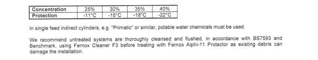
53 FERNOX ALPHI-11 PRODUCT DATA Page 53
54 Page 54
55 Page 55

56
Design, Installation & Servicing Instructions. A total hot water and heating thermal store that can also make the most of renewable energy
 A total hot water and heating thermal store that can also make the most of renewable energy Design, Installation & Servicing Instructions All models comply with the Hot Water Association specification
Unvented Calorifier Range. Operating and Maintenance Manual. For Models & 500
 Unvented Calorifier Range. Operating and Maintenance Manual. For Models 125 300 & 500 Telephone 08456 448802 Fax 08456 448803 Emial info@mhgheating.co.uk Web www.mhgheating.co.uk TABLE OF CONTENTS. Section
SYSTEMATE benchmark DESIGN, INSTALLATION AND SERVICING INSTRUCTIONS
 SYSTEMATE 2000 DESIGN, INSTALLATION AND SERVICING INSTRUCTIONS Gas Council Approved Reference Numbers SysteMate 125 97-317-26 SysteMate 145 97-317-27 SysteMate 185 97-317-28 SysteMate 210 97-317-29 SysteMate
BOILERMATE CP INSTRUCTION MANUAL DESIGN, INSTALLATION & SERVICING ONE NAME. EVERY SOLUTION.
 BOILERMATE CP MAINS PRESSURE HOT WATER THERMAL STORE FOR USE WITH CENTRAL PLANT BOILERS INSTRUCTION MANUAL DESIGN, INSTALLATION & SERVICING ONE NAME. EVERY SOLUTION. WWW.GLEDHILL.NET ISSUE 6.: JUNE 08
SYSTEMATE 2000 DESIGN, INSTALLATION AND SERVICING INSTRUCTIONS
 SYSTEMATE 2000 DESIGN, INSTALLATION AND SERVICING INSTRUCTIONS PLEASE LEAVE THESE INSTRUCTIONS IN THE POCKET PROVIDED ON THE BACK OF THE FRONT PANEL Gas Council Approved Reference Numbers SysteMate 125
BOILERMATE 2000 DESIGN, INSTALLATION AND SERVICING INSTRUCTIONS
 BOILERMATE 2000 DESIGN, INSTALLATION AND SERVICING INSTRUCTIONS Gas Council Approved Reference Numbers BoilerMate 125 89-317-04A BoilerMate 145 89-317-05A BoilerMate 185 89-317-06A BoilerMate 210 89-317-07A
PULSACOIL ECO STAINLESS
 PULSACOIL ECO STAINLESS THERMAL STORE SPECIFICALLY DESIGNED FOR APARTMENTS INSTRUCTION MANUAL DESIGN, INSTALLATION & SERVICING ONE NAME. EVERY SOLUTION. WWW.GLEDHILL.NET ISSUE 4: DECEMBER 07 Section Page
Instructions for Use Installation and Servicing
 0020004886A 18.01.05 Instructions for Use Installation and Servicing To be left with the user 12563 115-150-175-200-250-300 Unvented hot water storage cylinders Glow-worm, Nottingham Road, Belper, Derbyshire.
BOILERMATE CP INSTRUCTION MANUAL DESIGN, INSTALLATION & SERVICING ONE NAME. EVERY SOLUTION.
 BOILERMATE CP MAINS PRESSURE HOT WATER THERMAL STORE FOR USE WITH CENTRAL PLANT BOILERS INSTRUCTION MANUAL DESIGN, INSTALLATION & SERVICING ONE NAME. EVERY SOLUTION. WWW.GLEDHILL.NET ISSUE 6: SEPTEMBER
BOILERMATE ECO SP INSTRUCTION MANUAL DESIGN, INSTALLATION & SERVICING ONE NAME. EVERY SOLUTION.
 BOILERMATE ECO SP MAINS PRESSURE HOT WATER THERMAL STORE FOR USE WITH SEALED SYSTEM STEM BOILERS INSTRUCTION MANUAL DESIGN, INSTALLATION & SERVICING ONE NAME. EVERY SOLUTION. WWW.GLEDHILL.NET ISSUE 1:
Alpha FlowSmart 25 and 50
 Installation and Servicing Instructions Alpha FlowSmart 25 and 50 Hot Water System incorporating a Flue Gas Heat Recovery Device, Primary Store and an Alpha CD Condensing Combination Boiler For Technical
Installation and Servicing Instructions. Alpha FlowSmart
 Installation and Servicing Instructions Alpha FlowSmart Hot Water System incorporating an Alpha InTec 30/40GS Condensing Combination Boiler with Integrated Flue Gas Heat Recovery Device and wall mounted
benchmark ELECTRAMATE /12KW MODEL DESIGN, INSTALLATION AND SERVICING INSTRUCTIONS
 ELECTRAMATE 000-70/1KW MODEL DESIGN, INSTALLATION AND SERVICING INSTRUCTIONS benchmark TM The code of practice for the installation, commissioning & servicing of central heating systems A COMBINED PRIMARY
BOILERMATE BP INSTRUCTION MANUAL DESIGN, INSTALLATION & SERVICING ONE NAME. EVERY SOLUTION.
 BOILERMATE BP MAINS PRESSURE HOT WATER THERMAL STORE FOR USE WITH GAS OR OIL BOILERS INSTRUCTION MANUAL DESIGN, INSTALLATION & SERVICING ONE NAME. EVERY SOLUTION. WWW.GLEDHILL.NET CONTENTS ISSUE 5: SEPTEMBER
SEALED THERMAL STORE
 ISSUE 3 0717 INSTALLATION AND USER GUIDE ENERGYMANAGER SEALED THERMAL STORE ADVANCE APPLIANCES LTD PLEASE RETAIN AND ENSURE SERVICE RECORDS ARE KEPT UP TO DATE. SCHEMATIC DIAGRAM OF ENERYMANAGER THERMAL
Commissioning Pack. Heating and Hot Water Heat Pumps. IMPORTANT DOCUMENTS To Be Kept At All Times. With Equipment. Accredited Ecodan Installer:
 Accredited Ecodan Installer: Telephone: Email: Address: Commissioning Pack Heating and Hot Water Heat Pumps IMPORTANT DOCUMENTS To Be Kept At All Times With Equipment IMPORTANT This Sheet Must Be Kept
PULSACOIL ECO STAINLESS
 PULSACOIL ECO STAILESS THERMAL STORE SPECIFICALLY DESIGED FOR APARTMETS ISTRUCTI MAUAL DESIG, ISTALLATI & SERVICIG E AME. EVERY SOLUTI. WWW.GLEDHILL.ET DESIG ISSUE : DECEMBER 07 Section Page DESIG Introduction
TABLE OF CONTENTS TECHNICAL DOCUMENTATION 03. Technical Data Electrical Details Connection Details Dimensions Standing Losses
 INSPIRED H I G H H O T EF F ICIENCY E F F I C I E N C Y W A T E R S Y S T E M S E XT REME HIGH EFFICIENCY HO T W AT ER SY ST EMS w i th I N JECT I O N DYN A M I C S T ECHN I CAL DO CUME N TA T I O N I
THERMflow Thermal Store Cylinders
 THERMflow Thermal Store Cylinders Technical Manual Tel: (01592) 611123 www.mcdonaldwaterstorage.com September 2018 THERMflow Thermal Store Tank Technical Manual Manual must be completed by Installer and
Extreme Domestic Hot Water Loading System TECHNICAL DOCUMENTATION. Issue 11/09
 I N S P I R E D E F F I C I E N C Y Extreme Domestic Hot Water Loading System TECHNICAL DOCUMENTATION Issue 11/09 Technical data Description Extreme 200 Extreme 300 Extreme 500 Weight (empty) kg 63 77
Alpha CombiMax 350 and 600
 Installation and Servicing Instructions Alpha CombiMax 350 and 600 Unvented Hot Water Store for use with the Alpha 240/280 Range of Gas Fired Combination Boilers For Technical help or for Service call...
Torrent GreenHeat. Design, Installation & Servicing Instructions. Open vented thermal store providing heating and mains pressure hot water
 Torrent GreenHeat Open vented thermal store providing heating and mains pressure hot water Design, Installation & Servicing Instructions Models covered in this manual Torrent GreenHeat OV TGH140-TGH350
PulsaCoil Stainless. Design, Installation & Servicing Instructions. Hot water cylinder utilising off-peak electric. Models covered in this manual
 PulsaCoil Stainless Hot water cylinder utilising off-peak electric Design, Installation & Servicing Instructions Models covered in this manual PulsaCoil PCS 50 PulsaCoil PCS 80 PulsaCoil PCS 0 ISSUE 6:
ADVANCE ECB ELECTRIC COMBINATION BOILER
 ISSUE ISSUE 45 0115 0317 INSTALLATION AND USER GUIDE ADVANCE ECB ELECTRIC COMBINATION BOILER ADVANCE APPLIANCES LTD HOUSEHOLDER - PLEASE RETAIN AND ENSURE SERVICE RECORDS ARE KEPT UP TO DATE 1 SCHEMATIC
UNIQ HEAT BATTERIES REFERENCE MANUAL_V2.2. Version: 2018_07_19_v2.2
 UNIQ HEAT BATTERIES REFERENCE MANUAL_V2.2 Version: 2018_07_19_v2.2 Abstract This is a quick reference guide for selecting the UniQ range of heat batteries for the required application. For designing a
TORRENT STAINLESS INSTRUCTION MANUAL DESIGN, INSTALLATION & SERVICING ONE NAME. EVERY SOLUTION.
 TORRENT STAINLESS OPEN VENTED STAINLESS STEEL THERMAL STORE PROVIDING HEATING AND MAINS PRESSURE HOT WATER INSTRUCTION MANUAL DESIGN, INSTALLATION & SERVICING ONE NAME. EVERY SOLUTION. WWW.GLEDHILL.NET
StainlessLite HP. Design, Installation & Servicing Instructions. Unvented cylinders specifically designed to work with a heat pump
 StainlessLite HP Unvented cylinders specifically designed to work with a heat pump Design, Installation & Servicing Instructions Models covered in this manual Stainless Lite HP SOL Indirect 180-400 litres
Torrent Stainless. Design, Installation & Servicing Instructions. Open vented stainless steel thermal providing both heating and hot water
 Torrent Stainless Open vented stainless steel thermal providing both heating and hot water Design, Installation & Servicing Instructions Models covered in this manual Torrent Stainless Solar Indirect 250-400
CUBEflow Thermal Store Tank
 CUBEflow Thermal Store Tank Installation & Technical Manual Tel: (01592) 611123 www.mcdonaldwaterstorage.com September 2018 CUBEflow Thermal Store Tank, Installation & Technical Manual Manual must be completed
INTRODUCTION STORAGE PRIOR TO INSTALLATION. Expansion Vessel Hose. Part No High Flow Rate Inlet Control Set. Part No.
 INTRODUCTION The Worcester Greenskies cylinder is a Stainless Steel Unvented Twin Coil Storage vessel specifically designed to be installed in conjunction with the Worcester Greenskies solar package. Should
S T O R E R A N G E C Y L I N D E R & G R A N T FEATURES: GRANT MONOWAVE UNVENTED DIRECT AND INDIRECT SINGLE-COIL CYLINDERS
 G R A N T C Y L I N D E R & S T O R E R A N G E High Efficiency Direct and Indirect Hot Water Storage Solutions FEATURES: GRANT MONOWAVE UNVENTED DIRECT AND INDIRECT SINGLE-COIL CYLINDERS GRANT DUOWAVE
PulsaCoil Stainless. Design, Installation & Servicing Instructions. Hot water cylinder utilising off-peak electric. Models covered in this manual
 PulsaCoil Stainless Hot water cylinder utilising off-peak electric Design, Installation & Servicing Instructions Models covered in this manual PulsaCoil PCS 150 PulsaCoil PCS 180 PulsaCoil PCS 220 ISSUE
DIGITAL MODULATING ELECTRIC BOILERS FOR CENTRAL HEATING AND DOMESTIC HOT WATER
 INSTALLATION INSTRUCTIONS AND USER GUIDE MATTIRA DIGITAL MODULATING ELECTRIC BOILERS FOR CENTRAL HEATING AND DOMESTIC HOT WATER MAC15B Please read these instructions before installing or using this appliance
INSTALLATION MANUAL. Ecoline Geo RI HP PLEASE LEAVE THIS MANUAL WITH THE OSO UNIT AFTER INSTALLATION
 PLEASE LEAVE THIS MANUAL WITH THE OSO UNIT AFTER INSTALLATION Ecoline Geo RI HP INSTALLATION MANUAL The Ecoline GEO is an indirect unvented cylinder designed and approved for use with a heat pump. The
INSTALLATION & TECHNICAL MANUAL
 The COMET Range of Boilers the ultimate solution for central heating INSTALLATION & TECHNICAL MANUAL If you require any further assistance: Telephone: 01698 820533 Fax: 01698 825697 E-mail: info@electric-heatingcompany.co.uk
Furrows Business Park, Haybridge Road Wellington, Telford, Shropshire TF1 2FE
 WATERHEATER MANUFACTURERS ASSOCIATION Tel 01952 257963 Fax 01952 253452 Furrows Business Park, Haybridge Road Wellington, Telford, Shropshire TF1 2FE www.telford-group.com STAINLESS PRODUCTS Tornado &
Installation and Commissioning Manual
 Manual Advance Buffer Vessels for Ground Source Heat Pump Systems Installation and Commissioning Manual Copyright 2015 Kensa Heat Pumps Ltd Page 1 of 12 Contents Page Section Description Page 1... Safety
Installation and Servicing Instructions
 Installation and Servicing Instructions Alpha HE CB25/33 and HE SY25 Wall Mounted, Fan Assisted, Room Sealed, Gas Fired, High Efficiency Condensing Boiler Range For Technical help or for Service call...
Baxi Maxflow Combi WM
 Baxi Maxflow Combi WM Gas Fired Wall Mounted Combination Boiler with Unvented Hot Water Storage Please keep these instructions safe. Should you move house, please hand them over to the next occupier. User
TORRENT ECO INSTRUCTION MANUAL DESIGN, INSTALLATION & SERVICING ONE NAME. EVERY SOLUTION.
 TORRENT ECO OPEN VENTED THERMAL STORE PROVIDING HEATING AND MAINS PRESSURE HOT WATER INSTRUCTION MANUAL DESIGN, INSTALLATION & SERVICING ONE NAME. EVERY SOLUTION. WWW.GLEDHILL.NET These instructions should
CPC-150-ABIAB. Important Installation Notes.
 6 7 8 9 10 28 11 20 19 18 13 4 1 17 23 2 3 5 30 HX14 Pandora Heat Bank thermal store [] 150 litres, 530mm diameter x 1300mm high L18-14 plate heat exchanger for mains pressure hot water (30 l/min), Heatguard
Baxi System 100 HE Plus. User s Operating Instructions. Wall Mounted Powered Flue Condensing Gas Fired Central Heating Boiler
 User s Operating Instructions Baxi System 100 HE Plus Wall Mounted Powered Flue Condensing Gas Fired Central Heating Boiler Please keep these instructions safe. Should you move house, please hand them
Design, Installation, User & Servicing Instructions
 Design, Installation, User & Servicing Instructions An unvented hot water storage appliance complying with the requirements of Building Regulations Approved Document G3 and manufactured in accordance with
Combined electric boiler and domestic hot water store
 Combined electric boiler and domestic hot water store Electromax Electromax Underfloor 95 900 825 Issue 5 Introduction 03 Heatrae Sadia s Electromax boiler provides wet central heating and domestic hot
Baxi Maxflow Combi FS
 Baxi Maxflow Combi FS Gas Fired Floor Standing Combination Boiler with Unvented Hot Water Storage Please keep these instructions safe. Should you move house, please hand them over to the next occupier.
AquaFlo II. Issue 3 December Please read these instructions carefully before commencing installation of the AquaFlo unvented water heater
 Installation, Maintenance and User Instructions AquaFlo II Issue 3 December 2011 Please read these instructions carefully before commencing installation of the AquaFlo unvented water heater Please leave
Vote for your Installer of the year at HEATSLAVE
 Vote for your Installer of the year at www.worcester-bosch.co.uk HEATSLAVE 12/14, 15/19, 20/25, 26/32 FLOOR-STANDING OIL-FIRED COMBINATION BOILERS FOR CENTRAL HEATING AND MAINS-FED DOMESTIC HOT WATER USER
Design, Installation, User & Servicing Instructions
 Design, Installation, User & Servicing Instructions An unvented hot water storage appliance complying with the requirements of Building Regulations Approved Document G3 and manufactured in accordance with
Unvented Direct & Indirect Hot Water Cylinders (400L L)
") Unvented Direct & Indirect Hot Water Cylinders (400L - 2500L) Important Please read & understand all these instructions before commencing installation. Please leave this manual with the customer for future
Unvented Direct & Indirect Hot Water Cylinders (400L - 2500L) Important Please read & understand all these instructions before commencing installation. Please leave this manual with the customer for future
unistor Instructions for Installation and Use Unvented hot water storage cylinder
 Instructions for Installation and Use unistor Unvented hot water storage cylinder VIH GB 5 S VIH GB 55 S VIH GB 80 S VIH GB 0 S VIH GB 60 S VIH GB 30 S GB Contents Page Description......................
Baxi Combi 133 HE Plus Baxi Combi 100 HE Plus Baxi Combi 80 HE Plus. User s Operating Instructions
 User s Operating Instructions Baxi Combi 133 HE Plus Baxi Combi 100 HE Plus Baxi Combi 80 HE Plus Gas Fired Wall Mounted Condensing Combination Boiler Please keep these instructions safe. Should you move
StainlessLite Horizontal
 StainlessLite Horizontal Unvented mains pressure water storage in Duplex stainless steel Design, Installation & Servicing Instructions Models covered in this manual Stainless Lite Horizontal Indirect 180-300
PLEASE LEAVE THIS MANUAL WITH THE OSO UNIT AFTER INSTALLATION INSTALLATION MANUAL
 PLEASE LEAVE THIS MANUAL WITH THE OSO UNIT AFTER INSTALLATION 0 RD 0 RI 0000-06 IM/ IM/a INSTALLATION MANUAL This manual gives detailed advice for installation and should be read carefully prior to fitting
Design, Installation & Servicing Instructions
 A mains pressure hot water supply system incorporating an off peak electric thermal store Design, Installation & Servicing Instructions Model Numbers PulsaCoil PCA 100E PulsaCoil PCA 120E PulsaCoil PCA
PLEASE LEAVE THIS MANUAL WITH THE OSO UNIT AFTER INSTALLATION INSTALLATION MANUAL
 PLEASE LEAVE THIS MANUAL WITH THE OSO UNIT AFTER INSTALLATION SOLARCYL IM/SC INSTALLATION MANUAL This manual gives detailed advice for installation and should be read carefully prior to fitting any unvented
Installation and User Instructions HS10U, HS15U.
 Installation and User Instructions HS10U, HS15U. MULTIPOINT Please read and understand these instructions before starting work. Please leave this leaflet with the user following installation PACK CONTENTS
Ecodan Air Source Heat Pump and Flow Temperature Controller 2
 FTC STANDALONE Design, Installation & Servicing Instructions September 2011 Ecodan Air Source Heat Pump and Flow Temperature Controller 2 Flow temperature Controller 2 model Number PAC-IF03IB-E (FTC2)
Installation and Servicing Instructions. Alpha CD24C/32C
 Installation and Servicing Instructions Alpha CD24C/32C Range of Wall Mounted, Fan Assisted, Room Sealed, Gas Fired, High Efficiency Condensing Combination Boilers For Technical help or for Service call...
CPC-180-ABNAB. 180 litres, 535mm x 1550mm high
 6 8 9 10 1 3 7 2 4 11 13 17 5 28 21 20 19 18 30 Wiring Pandora Heat Bank. 100kW Plate Heat Exchanger with 22mm Thermostatic Mixing Valve. Indirectly Heated. Cylinder Thermostat. Manually Filled store -
STAINLESSLITE PRO, PRE-PLUMBED SYSTEM PLUS AND SYSTEM READY
 STAINLESSLITE PRO, PRE-PLUMBED SYSTEM PLUS AND SYSTEM READY UNVENTED MAINS PRESSURE HOT WATER STORAGE INSTRUCTION MANUAL DESIGN, INSTALLATION & SERVICING ONE NAME. EVERY SOLUTION. WWW.GLEDHILL.NET These
STAINLESSLITE PLUS INSTRUCTION MANUAL DESIGN, INSTALLATION & SERVICING ONE NAME. EVERY SOLUTION. UNVENTED MAINS PRESSURE HOT WATER STORAGE
 STAINLESSLITE PLUS UNVENTED MAINS PRESSURE HOT WATER STORAGE INSTRUCTION MANUAL DESIGN, INSTALLATION & SERVICING ONE NAME. EVERY SOLUTION. WWW.GLEDHILL.NET These instructions should be read in conjunction
Installation & Technical Guide. Domestic & Commercial.
 Installation & Technical Guide Domestic & Commercial www.challisbooster.com www.challisboosterplus.com Installation and Technical Guide Domestic and Commercial Challis Water Controls Europower House, Lower
PulsaCoil BP. Design, Installation & Servicing Instructions. Hot water cylinder utilising off-peak electric with an optional solar version
 PulsaCoil BP Hot water cylinder utilising off-peak electric with an optional solar version Design, Installation & Servicing Instructions Models covered in this manual PulsaCoil PCBP 120 PulsaCoil PCBP
INSTALLATION & TECHNICAL MANUAL
 The FUSION Range of Boilers INSTALLATION & TECHNICAL MANUAL If you require any further assistance: Telephone: 01698 820533 Fax: 01698 825697 E-mail: info@electric-heatingcompany.co.uk Or visit our website
Installation & User Instructions
 PROVISIONAL COPY Grant ThermaWave System Thermal Store Range Installation & User Instructions Part No. DOC 78. Rev 01. June 2011 Contents 1 Introduction & General Requirements 3 1.1 Installation Requirements
ELECTRIC COMBINATION BOILER. (European Patent No: Design Right Protected.) TH12-450U MRK 2
 TH12-450U MRK 2") ELECTRIC COMBINATION BOILER (European Patent : 1757678. Design Right Protected.) TH12-450U MRK 2 INCLUDES THERMAL SOLAR & WOOD BURNING STOVE WITH WATER JACKET APPENDIX This product is suitable for connection
ELECTRIC COMBINATION BOILER (European Patent : 1757678. Design Right Protected.) TH12-450U MRK 2 INCLUDES THERMAL SOLAR & WOOD BURNING STOVE WITH WATER JACKET APPENDIX This product is suitable for connection
Unvented Direct & Indirect Hot Water Cylinders (400L L)
") Unvented Direct & Indirect Hot Water Cylinders (400L - 2500L) Important Please read & understand all these instructions before commencing installation. Please leave this manual with the customer for future
Unvented Direct & Indirect Hot Water Cylinders (400L - 2500L) Important Please read & understand all these instructions before commencing installation. Please leave this manual with the customer for future
ADVANCE UNIVERSAL MULTI-FUEL THERMAL STORE
 ISSUE 6 1016 INSTALLATION AND USER GUIDE ADVANCE UNIVERSAL MULTI-FUEL THERMAL STORE ADVANCE APPLIANCES LTD PLEASE RETAIN AND ENSURE SERVICE RECORDS ARE KEPT UP TO DATE. IMPORTANT: Gravity circultation
ZIP Varipoint III. Installation, Maintenance and User Instructions. Models VP303, VP503 VP803, VP953 direct unvented water heaters. Issued August 2008
 Varipoint cover qxd:varipoint cover qxd 22/8/08 11:14 Page 1 Installation, Maintenance and User Instructions ZIP Varipoint III Models VP303, VP503 VP803, VP953 direct unvented water heaters Issued August
Installation and Servicing Instructions. Alpha CB50
 Installation and Servicing Instructions Alpha CB50 Wall Mounted, Fan Assisted, Room Sealed, Gas Fired Combination Boiler with Unvented Hot Water Storage For Technical help or for Service call... ALPHA
Installation and Servicing Instructions. Alpha CD50
 Installation and Servicing Instructions Alpha CD50 Wall Mounted, Fan Assisted, Room Sealed, Gas Fired, High Efficiency, Condensing Combination Boiler with Unvented Hot Water Storage For Technical help
StainlessLite. Design, Installation & Servicing Instructions. Unvented mains pressure water storage in Duplex stainless steel
 StainlessLite Unvented mains pressure water storage in Duplex stainless steel Design, Installation & Servicing Instructions Models covered in this manual Stainless Lite Direct 90-400 litres Stainless Lite
Electronic Dual Cylinder Thermostat Installation Instructions
 ESCTDEB Electronic Dual Cylinder Thermostat Installation Instructions Thank you for choosing ESi Controls. All our products are tested in the UK so we are confident this product will reach you in perfect
User's Instructions. Alpha CB50
 User's Instructions Alpha CB50 Wall Mounted, Fan Assisted, Room Sealed, Gas Fired Combination Boiler with Unvented Hot Water Storage (From Boiler Serial No. 27B32500001) For Technical help or for Service
H o t Wa te r Syste m s. Ultrasteel. Unvented Hot Water Cylinders. Exceeding the Standard
 H o t Wa te r Syste m s Unvented Hot Water Cylinders Ultrasteel Exceeding the Standard STEP UP TO... Ultrasteel... is the new Albion unvented hot water storage system. Based on the company s experience
Link-Up. Solid Fuel Association Guide to Central Heating.
 Solid Fuel Association Guide to Central Heating Link-Up Combining solid fuel with other central heating technologies using various methods ranging from a simple link-up to a fully integrated thermal store
Stored Water District Heating Interface Units. Heat Interface Units
 Stored Water District Heating Interface Units Heat Interface Units Why choose Elson Elson are a Heatrae Sadia company, the UK s leading manufacturer of hot water solutions utilising thermal store technology
DESIGN, INSTALLATION AND SERVICE INSTRUCTIONS
 A wall mounted high efficiency condensing Gledhill Boiler DESIGN, INSTALLATION AND SERVICE INSTRUCTIONS GENERAL This high efficiency wall mounted condensing boiler is designed to provide central heating
1845 Tech Manual.qxd 23/11/05 1:20 pm Page 2 EXCELSIOR UNVENTED WATER HEATERS INSTALLATION MANUAL. Design for living
 1845 Tech Manual.qxd 23/11/05 1:20 pm Page 2 EXCELSIOR UNVENTED WATER HEATERS INSTALLATION MANUAL Design for living 1845 Tech Manual.qxd 23/11/05 1:21 pm Page 3 TECHNICAL DATA & INSTALLATION INSTRUCTIONS
Performance on demand
 Eliminate low mains water pressure problems with Flomate. Designed for use with unvented (mains pressure) systems to provide a simple to install, cost effective solution to the increasingly common problem
Design, Installation & Servicing Instructions
 A mains pressure hot water supply system incorporating an off peak electric thermal store Design, Installation & Servicing Instructions Model Numbers PulsaCoil 145 PulsaCoil 185 PulsaCoil 215 PulsaCoil
Installation and Servicing Instructions. Alpha GasSaver GS-1
 Installation and Servicing Instructions Alpha GS-1 Passive Flue Gas Heat Recovery Device (PFGHRD) for use with an Alpha CD Condensing IMPORTANT: Read these instructions BEFORE installing the boiler For
Welcome to our Training Centre. Living Environmental Systems Division
 1 Welcome to our Training Centre 2 Green Gateway Initiative The Green Gateway Initiative is a bold and ambitious 10-point plan that points the way to a reduction of over 3 million tonnes of CO2 per year,
Mains Pressure Hot Water from an existing vented copper cylinder... Allows the cold water tank to be removed, freeing loft space.
 DPS Hi-Flow Mains Pressure Hot Water from an existing vented copper cylinder... Converts an existing hot water cylinder to provide potable mains pressure hot water at high flow rates to all existing outlets.
Advance Stainless Steel Unvented Hot Water Cylinders for Heat Pump Systems. Installation and Commissioning Manual
 Manual Advance Stainless Steel Unvented Hot Water Cylinders for Heat Pump Systems Installation and Commissioning Manual PLEASE RETAIN AND ENSURE SERVICE RECORDS ARE KEPT UP TO DATE. Copyright 2017 Kensa
Design, Installation & Servicing Instructions
 An unvented hot water storage unit complying with the requirements of Building Regulations Approved Document G3 and manufactured in accordance with BS EN 12897, the specification for the unvented water
Torrent ECO. The final piece in your heating and hot water system. Open vented thermal store providing heating and mains pressure hot water
 Torrent ECO Open vented thermal store providing heating and mains pressure hot water SUPPLIERS TO THE MERCHANT TRADE FOR OVER 40 YEARS The final piece in your heating and hot water system What is a thermal
Electromax Combined Electric Flow Boiler and Direct Unvented Hot Water Cylinder Installation and Servicing Instructions
 Electromax Combined Electric Flow Boiler and Direct Unvented Hot Water Cylinder Installation and Servicing Instructions Contents SECTION PAGE SECTION PAGE 1.0 Introduction 1.1 Important Notes 3 1.2 Basic
Hotflo. Unvented point of use hot water
 Unvented point of use hot water We developed the range for people who need a hot water supply for two to three basins or sinks. Flexible siting is a key design feature that we insisted upon because it
SUPPLEMENT. Part No. DOC 25 Rev. 09 November SUPPLEMENTARY INSTALLATION and USER INSTRUCTIONS. COMBI 90 OUTDOOR MODULE MkII
 SUPPLEMENT Part No. DOC 25 Rev. 09 November 2004 SUPPLEMENTARY INSTALLATION and USER INSTRUCTIONS COMBI 90 OUTDOOR MODULE MkII For use with Kerosene or Gas Oil TO BE READ IN CONJUNCTION WITH THE INSTRUCTION
TERMO ELECTRIC BOILERS MANUAL OSO TERMO RS -E OSO TERMO PLUS - E OSO TERMO PTV E
 TERMO ELECTRIC BOILERS MANUAL OSO TERMO RS -E OSO TERMO PLUS - E OSO TERMO PTV E B C Contents 1. Introduction... 1 1.1. Applicable documents... 1 1.2. Retention of documents... 1 1.3. Features and benefits...
Quantum. Installation, User and Service Manual. Hot Spring
 Hot Spring Domestic Hot Water Cylinder Storage Capacities 90, 125, 150, 170, 200, 250 and 300 Litres 1 Important - This Manual should be left with the householder after installation Index Section Page
Unvented Electric Water Heater 10/15 litre Undersink
 Unvented Electric Water Heater 10/15 litre Undersink Fitting Instructions and User Guide 1 CONTENTS SECTION PAGE 1.0 INTRODUCTION 2 2.0 TECHNICAL SPECIFICATION 3 3.0 INSTALLATION 4 4.0 COMMISSIONING 9
CROWN WATER HEATERS CPU10 - CPU15 CPOS10 - CPOS15
 CROWN WATER HEATERS CPU10 - CPU15 CPOS10 - CPOS15 COMPACT PLUS 10 and 15 Litre Unvented Under and Over Sink Water Heater INSTALLATION AND USER GUIDE 1 DIMENSIONS 10L - 250mm 15L - 310mm 100mm 80mm 410mm
Torrent MultiFuelStore HP
 Torrent MultiFuelStore HP Thermal store for use with a heat pump to provide heating and hot water Design, Installation & Servicing Instructions Models covered in this manual Torrent MultiFuelStore HP 180-450
Alpha CD13R,18R and 24R
 Installation and Servicing Instructions Alpha CD3R,8R and 24R Wall Mounted, Fan Assisted, Room Sealed, Gas Fired, High Efficiency Condensing Regular Boiler Range For Technical help or for Service call...
Quartz. Digital. Bath with bath waste filler. Quartz Digital Bath with bath waste filler installation instuctions page 1
 Quartz Digital Bath with bath waste filler The Waste Electrical and Electronic Equipment (Producer Responsibility) Regulation 2004 This product is outside the scope of the European Waste Electrical and
ADVANCE ELECTRIC THERMAL STORE
 ISSUE 13 1118 INSTALLATION AND USER GUIDE ADVANCE ELECTRIC THERMAL STORE ADVANCE APPLIANCES LTD HOUSEHOLDER PLEASE RETAIN AND ENSURE SERVICE RECORDS ARE KEPT UP TO DATE. 2 INTRODUCTION Advance thermal
HW3 Handwash Installation and Operating Instructions
 HW3[16]instructions 10/12/15 14:05 Page 1 HW3 Handwash Installation and Operating Instructions IMPORTANT SAFEGUARDS SPECIFICATION: HW3 RATING: 230-240V, 3000W, ~50Hz; DIMENSIONS: 170w x 190h x 80d mm;