Posizione logo. Instructions for use MB17 / MB22. LINA MB ENG - Rev. 3.1
|
|
|
- Rosaline Lane
- 6 years ago
- Views:
Transcription


1 Posizione logo Instructions for use LINA MB ENG - Rev. 3.1 MB17 / MB22


2 Symbols Symbols displayed on the product and/or used in this manual: WARNING! Risk of injury ATTENTION! To prevent damage occurring General explanations, without risk to persons or objects HOT SURFACES! Risk of burns HOT STEAM! Risk of burns Call service Thermo washer disinfectable Consult instruction for use Do not dispose of with normal waste 2
3 Contents 1. Introduction Unpacking Safety advice Installation and start-up Programming Running a sterilization cycle Maintenance Troubleshooting, alarms and messages Recycling and disposal APPENDICES 1 Technical data Maintenance of dental handpieces Sterilization load preparation Bowie & Dick test Helix test Vacuum test Water quality Example of a cycle data report Accessories and spare parts Helix test documentation form
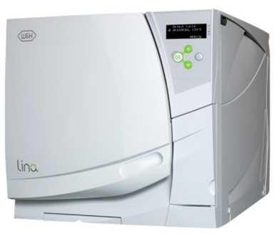
4 1. Introduction For your safety and the safety of your patients The purpose of this manual is to provide you with information about LINA MB17/22 sterilizers to ensure: proper installation and set-up; optimal use; safe and reliable operation; compliance with regular maintenance and servicing requirements. Please carefully read the safety information in Chapter 3! Intended use of the product Small steam sterilizers are widely used for medical purposes, e.g. in general medical practices, dentistry, facilities for personal hygiene and beauty care and also veterinary practices. They are also used for materials and equipment, which are likely to come into contact with blood or body fluids, e.g. implements used by beauty therapists, tattooists, body piercers and hairdressers. The devices is intended for professional use only by trained people. About this manual All drawings, images and texts contained in this manual are the property of the manufacturer. All rights reserved. Even partial duplication of drawings, images or text is prohibited. The information contained in this document is subject to change without prior notice. Responsibility of the manufacturer The manufacturer can only accept responsibility for the safety, reliability and performance of the product when the product itself is installed, used and serviced in accordance with these instructions for use. Servicing by unauthorized persons invalidates all claims under warranty and any other claims. 4


5 Introduction Qualifications of the users There are two types of users who may operate the sterilizer: The Advanced user is the head of the clinic/practice, who is legally responsible for the efficiency of the hygiene protocol in place as well as the sterilization process. He/she is also responsible for the USERS training and the correct operation and maintenance of the equipment. The Users are the persons who use the sterilizer according to the ADVANCED USER s instructions. They must be trained in operating the sterilizer and in its safe use. Training must be regular and evidence of the understanding shall be recorded. Conformity to European Standards and Directives Medical Device Directive 93/42/CEE for devices class IIb, in accordance with the Rule 15 Appendix IX of the above Directive. Directive 97/23/CEE (PED Pressure Equipment Directive) for every sterilization chamber designed and manufactured in conformity to the Appendix 1 and to the procedure described in the form D1 Annex III. Directive 2002/96/CEE (RAEE) for disposal of parts coming from electrical or electronic products. European standard EN13060 (small water steam sterilizers). See the Declaration of Conformity and the Warranty Card in the enclosed documents. 5


6 2. Unpacking If the sterilizer comes from a cold location, wait until all external and internal surfaces are free from moisture before switching it ON. The sterilizer must be removed from the box and transported by two people. Weight: LINA MB17: 38 kg LINA MB22: 40.5 kg Check the external conditions of the box and the sterilizer. In case of any damage, immediately contact your dealer or the shipping agent that has carried out the transport. The packaging of the product is environmentally friendly and can be disposed of by industrial recycling companies. However, we recommend to keep the original packaging should you ever have to ship or transport the sterilizer. Open the front door. All the accessories are in the sterilization chamber. Remove all items except the trays and the tray rack. 6


7 Contents of the package Tray (3 pieces total) Mains cable Reversible rack Funnel Tray holder Wall spacer Drain tube Fast guide Declaration of conformity Documentation CD Warranty card Works tests report 7
8 3. Safety advice The user is responsible for the proper installation, the correct use and maintenance of the sterilizer in accordance with the instructions listed in this manual. The sterilizer has not been designed for the sterilization of foodstuff or waste. Liquids may be sterilized only if the appropriate option is installed. The sterilizer must not be used in presence of explosive or flammable gases, vapours, liquids or solids. The chamber is automatically heated up to high temperature as soon as the sterilizer is switched on risk of burns! Ensure that the socket the mains cable is connected to is properly grounded. The trays and the sterilization load will be hot at the end of each cycle. Use tray or cassette holders to empty the sterilization chamber. Do not exceed the maximum load weight limits as specified in this manual (see Chapter 6 of the Instructions for use). Do not remove the name plate or any label from the sterilizer. To avoid electrical short circuits, do not pour water or any other liquids over the sterilizer. Switch off the sterilizer and unplug the mains cable before inspecting, carrying out maintenance or servicing the sterilizer. The low-voltage outlet in the rear of the sterilizer is for the connection of specific accessories only: do not connect any device other than those specifically supplied by the manufacturer. All electric devices connected to the sterilizer shall be of Insulation Class II (double insulated) or higher. Repairs, maintenance or service must be carried out by service technicians authorized by the manufacturer and using genuine spare parts only. In case of transport: Completely drain both water tanks (see section Water Tanks in Chapter 4 of the Instructions for use). Allow the sterilization chamber to cool down. Use original or appropriate packaging. 8

9 4. Installation and start-up Placement Place the sterilizer on a flat and level surface, far from sources of heat and from flammable materials. Do not place the sterilizer so that it is difficult to open the service door and operate on the controls in it. Do not place the sterilizer so that it is difficult to disconnect the power supply plug. Place the sterilizer in a well ventilated room. If installed in a cabinet, this shall be provided with an opening of at least 200x150 mm on the rear side. The sterilizer must not be operated in presence of explosive atmospheres. Required minimum clearances Back side: 50mm Right and left sides: 10 mm Upper side: As required for filling the water tank, 50 mm minimum Electrical connection The electrical power supply to the sterilizer must fulfil all applicable standards in the country of use, and must comply with the data label on the back of the sterilizer. Connect the cord set to the socket provided in the back of the sterilizer. Connect the mains cable to a wall outlet with the following characteristics: Single - phase V, 50/60 Hz, 8,75 A, on a dedicated circuit; Overvoltage category = II; 10 A differential circuit breaker with a sensitivity of 30 ma. The circuit breaker must be a certified type according to applicable norms; Maximum power consumption of the sterilizer is 1750 W; A grounded connection is essential. 9
10 Water tanks Filling the clean water tank Switch the sterilizer ON Slide the tank cover to the right to access the clean water tank inlet. Remove the cap from the tank inlet; Insert the funnel and fill the water tank with app. 3.5 litres of distilled or demineralized water; Once the clean water tank is almost full, an audible tone will sound; stop filling; Place the cap to close the tank; Slide the tank cover back into its original position. Use only high quality distilled or demineralized water (see Appendix 7). Do not add any chemical / additive to the water. Draining the used and clean water tank Open the service door at the front of the sterilizer. Put a container (4 litres min) below the sterilizer and insert into it the free end of the drain tube. Insert the drain tube into the right connector (grey) for the used water, or into the left connector (blue) for the clean water. Let the water flow from the tank completely. Press the push-button on top of the quick connector to dislodge the drain tube. 10


11 Chamber furniture Before touching the chamber furniture, ensure the sterilization chamber is cold: risk of burns! The chamber furniture consists of the trays, the tray rack and the steam diffuser plate. 2 1 Steam diffuser plate Ensure that the steam diffuser plate is firmly hooked in its position before starting a sterilization cycle. An improper positioning of the steam diffuser plate could result in bad steam quality and could impair the sterilization process, with risk of non sterile load and cross infection. Sterility at the end of the cycle is not guaranteed if the steam diffuser plate was not correctly placed. To hook the steam diffuser plate, slide it into the chamber until it gets engaged into the end hooks. To remove the steam diffuser plate, press it in the center of the end edge (1) and slide it outwards (2). Tray rack Insert the rack into the sterilizer chamber, align it at the center/bottom of the chamber and push it gently into position until it clicks. The chamber rack is reversible and can accommodate 5 trays horizontally or 3 cassettes vertically. If inserted in a 90 degree rotated position, the rack holds 3 trays or 3 cassettes horizontally. Usable space in the chamber LINA MB17: 195 x 195 x 297mm (WxHxD); equal to the volume of 11.5 litres. LINA MB22: 195 x 195 x 390mm (WxHxD); equal to the volume of 15 litres. 11
12 Controls and commands Front view Service door Water tank cover Tank filling cover - cap Bacteriological filter Mains switch Chamber door Display Control panel Service door Door pin Door seal Dust filter Sterilization chamber Clean water drain (blue) Used water drain (grey) 12
13 Controls and commands Rear view Serial communication port Pressure safety valve cover Accessories power socket Mains plug socket Mains cable guide Detail of the hydraulic connections (optional) Condenser vent Used water drain Water supply inlet 13
 appears.")
14 Controls and commands Switching ON the sterilizer Press the mains switch behind the service door to switch ON the sterilizer. The visual indicator on the mains switch turns green and the START screen (see next page) appears. SLEEP mode If the sterilizer is not used for 12 hours, (the time interval can be changed, see Chapter 5 - Programming) it will automatically switch to SLEEP mode. In SLEEP mode the display remains dark and the sterilizer chamber is no longer heated to save energy. Exit from SLEEP mode through any of the following actions: - Press any button on the control panel; - Open or (if it is open)close the chamber door. It is also possible to put the sterilizer into SLEEP mode manually: On the START screen, press the BACK button. A 10 second countdown will commence. At the end of the countdown the sterilizer will enter the SLEEP mode. The countdown can be stopped at any time by pressing the BACK button. 14
15 Display and icons First line Shows the title/purpose of the current page and invites you to take an action (e.g. select a cycle). Second line Shows the active option/action (preceded by the cursor >). By pressing OK, the active option/action will be selected/executed. Pressing UP or DOWN changes the active option/action. Warning, tank and printer icons The cursor (>) preceding an icon means that an information message is to be read. Third and fourth lines Show additional information about the active option/action. Padlock icon The cursor (>) preceding this icon informs that the door is safely locked. 15


.")

 is not working properly, or is OFF, or is disconnected from the sterilizer.")
16 Icons If one or more icons of the display are preceded by the cursor, please take the actions as outlined below: If an icon is preceded by the cursor, this means that an information message is present in the MESSAGES menu. Follow the instructions provided in Chapter 8 to read the relevant messages. General warning One or more messages require your attention, or an action is required (e.g. maintenance). Tank warning The clean water tank needs to be filled, or the used water tank has to be drained, or a message about the water quality is present. Printer An external device (printer, PC, etc.) is not working properly, or is OFF, or is disconnected from the sterilizer. Door locked The door is locked. During a sterilization cycle this does not indicate any anomaly. 16
17 Control buttons The control panel shows four buttons: UP button Moves to the upper item in the list. Increases a number or a parameter. ECO-B option This label reminds you that, when starting a cycle, you can choose the ECO-B mode by holding the OK button for 2 seconds (see Chapter 6). BACK button Aborts the action/function. Moves to the previous screen without confirming/making any changes nor saving any parameters. DOWN button Moves to the lower item in the list. Reduces/decreases a number or a parameter. OK button (confirmation button) Confirms the active option. Confirms a number or a date. Saves a configuration or a parameter. 17

18 5. Programming Initial setup Before using the sterilizer please program important parameters such as date, time, language, display backlight and contrast. This is done by means of the SETUP functions. Start screen and menu options When the sterilizer is switched ON, or when exiting from SLEEP mode, the default cycle program is displayed, preceded by the cursor. By pressing DOWN the other available cycle programs are displayed. Continuously press DOWN until the MENU option appears. Menu Confirm (OK) the MENU option to access all sub-menus and navigate through sub-menus with the UP and DOWN buttons. See the following pages for a complete description of the options available and how to use them. Setup Scroll (DOWN) to SETUP and confirm (OK) to access and set the main parameters of the sterilizer. See the following pages for a complete description of the parameters you can set and how to do it. 18

19 Table 1: list of the MENU options MENU (continues on next page) SUB-MENU WHAT IT DOES - Displays pending messages. Refer to Chapter 8 for a detailed list of messages. Select a previously recorded cycle. Press OK and then scroll the list of the recorded cycles with UP /DOWN. Press OK to select the cycle to be viewed or printed. Displays the selected cycle. Press UP/DOWN to scroll the cycle report. Prints the selected cycle. Press OK and scroll UP and DOWN to change the number of copies to (*) be printed. Once the value is displayed, press OK to print. Prints traceability labels for the selected cycle. Press OK and scroll UP and DOWN to change the (*) number of copies to be printed. Once the value is displayed, press OK to print. (*) Saves a cycle data file on a memory storage device (memory card or PC). Displays all the alarms that have occurred during sterilization cycles. (*) Prints all the alarms that have occurred of the sterilization cycles stored in memory. Sets important parameters of the sterilizer such as date, time, language, etc. Confirm (OK) to access all available options. Refer to TABLE 2 for a detailed list of options and related programming. (*) Enables the automatic water feed Press UP/DOWN to scroll the YES/NO options, (*) Enables water quality warnings based then press OK to enable/disable the function (*) on the external/internal sensor (warning), or BACK to exit without saving. Allows the user to change the current user level. Access to advanced level or service level is protected by codes. See How to log in as an advanced user in the following pages. Allows the user to enter the activation code in order to enable some optional features. (*) available/effective only if an endorsed device (printer, logger, PC, water supply, etc.) is connected and enabled in the SETUP menu. 19
20 Table 1: list of the MENU options (continued) MENU (continued from previous page) SUB-MENU (*) WHAT IT DOES Prints traceability labels to be stuck to the load pouches. Labels show the lot number and other parameters as specified in the LOT LABELS menu (see SETUP table). The number of labels will be requested: press UP/DOWN to increment/decrement the number, then press OK to print. After printing, the lot number is incremented by 1. Prints labels of a previous sterilization lot. The lot number and the number of labels will be requested: press UP/DOWN to increment/decrement the numbers, then press OK to print. Displays the device brand name; e.g. W&H. Displays the device model name; e.g. LINA MB22. Displays the serial number of the sterilizer; e.g Displays the total number of cycles executed by the sterilizer. Displays the status (number of cycles executed) of consumables. Permits the user to reset the counter to zero after replacing a consumable. See Chapter 7 (Maintenance) for details. Displays the number of cycles executed compared to the 4000 cycle service. Displays the number of cycles executed compared to the cycle service. Displays the current software version. Displays the current system software version. Displays the current version of the power firmware. Shows the identifier of the hardware key (label printer/service), if connected. Displays the software version of the PC/logger device, if connected. (*) available/effective only if an endorsed device (printer, logger, PC, water supply, etc.) is connected and enabled in the SETUP menu. 20
21 Table 2: Detail of the SETUP options MENU (continues on next page) SUB-MENU WHAT IT DOES AND HOW TO SET IT Sets the language. The active language is displayed: press OK and scroll other available languages with UP or DOWN. When the new language is displayed press OK to confirm, or BACK to exit without saving. Sets the date and time display formats. Press OK to access the function and then scroll with UP and DOWN until the preferred format is displayed. Press OK to confirm. Press BACK to exit without saving. Sets the time and date which will be used for the cycle report and for the delayed cycle start option. By pressing OK the cursor is positioned on the date. Change the month, year and the day with UP or DOWN. By pressing OK, the changes are saved and the cursor moves to the time setting. The procedure for setting the time is the same. During the procedure, you can press BACK to return to the SETUP menu without saving. Sets the operator or dental clinic name which will be used for the cycle report. There are 18 characters (capital letters and numbers) plus space, the dash and the point. You can store only one name. By pressing OK the saved name is displayed, or a series of dashes if no name is saved. Press UP and DOWN to change characters. Press OK to save a character and the cursor will move to the next character. To return to the previous character, press BACK. To go to the next character without changing it, just press OK without pressing either UP or DOWN. To go to the last character hold OK for two seconds. Press BACK on the first character to exit without saving. Press OK on the last character to save the name as displayed. Sets the time before the sterilizer will enter SLEEP mode. In SLEEP mode the sterilizer consumes less energy. It is advised to set a short SLEEP mode time in order to save energy. See Chapter 4 CONTROLS AND COMMANDS for a description of SLEEP mode. Press OK to view the current time. Press UP or DOWN to increase or decrease the time by increments of 10 minutes from 10 minutes to 12 hours. Press OK to save the time. Press BACK to exit without saving. Increases or decreases the sound volume. Press OK to view the current setting. To decrease or increase the volume press UP or DOWN: a sound will be emitted as an example. Press OK to save the new setting. Press BACK to exit without saving. Sets the display contrast. Press OK to view the current setting. Press UP to increase or DOWN to decrease the contrast. Press OK to save the new setting, or BACK to exit without saving. Sets the device that is connected to the serial port. See note (*) for setting instructions. Serial port not in use. Serial port used for cycle report printer. Serial port used for label printer (available only if a label printer is present and configured). Serial port used for an external PC/LOGGER (see APPENDIX 9 Accessories). 21
22 Table 2: Detail of the SETUP options (continued) MENU (continued from previous page) SUB-MENU (**) (**) (**) (**) (***) (**) (***) (**) (**) Sets the preheating mode See note (*) for instructions Sets the HOT SURFACES warning See note(*) for instructions Sets the PC/LOGGER warning See note(*) for instructions Sets the printer model Sets the speed of the printer port WHAT IT DOES AND HOW TO SET IT See note (*) for instructions. Preheats the chamber ONLY if the chamber door is closed. Chamber is never preheated. A warning appears while the door is open and the chamber hot. No warning appears. A warning appears if the PC/LOGGER is not detected or if data saving fails. No warning appears. Sets the unit for pressure Sets the unit for temperature (*) Enables automatic printing of the cycle report. See note (*) for instructions. (**) Enables printing the plateau temperature at fixed time steps (use the next option to set the step). (**) Sets the time step and enables printing the plateau temperature at the set time interval. Sets the label printer model See note(*) for instructions Set the horizontal and vertical offsets of the label layout. Adjust the values according to note(*), until the printout is properly centred in the label (*) Sets the number of labels to be printed automatically at the end of each successful sterilization cycle. The user will be asked for the number of labels to be printed at the end of each successful sterilization cycle. Press UP/DOWN to increase/decrease, OK to confirm. Press BACK to exit without printing. The pre-set number of labels (see AUTOMATIC PRINTING ) will be printed at the end of each successful sterilization cycle, with no further request for manual printing. Sets the expiry time (to be programmed in weeks) for labels. The software will automatically add the programmed (*) expiry time to the current date and print it on labels. If it is set to zero, no expiry date will be printed on labels. (*) Sets the lot number to be printed on the labels (it will be increased at each lot). (*) Sets the information (user name, time/date, expiry date) to be printed on the labels. Note (*) The current setting is displayed: press OK to enable changes and then UP/DOWN to scroll the available options. Press OK to set a new option, or BACK to exit without saving. Note (**) This option is available for advanced users only. See the next page for instructions about how to log in as an advanced user. Note (***) This option is available only if a compatible label printer is connected. 22
23 How to log on as an advanced user Some programmable options of the LINA MB sterilizer can be changed only after logging in as an advanced user. This is to prevent accidental changes or unexpected operation of the sterilizer. Hiding a cycle program, making it inaccessible to users, is an example of option that can be accessed by advanced users only. Use the UP, DOWN and OK buttons to browse the menu, choosing the following options in sequence: MENU SERVICE CURRENT LEVEL. The current level is now displayed. If you want to change it, press OK. Press OK on the LAST number to confirm the code. Press BACK on the FIRST number to abort the procedure. The screen as shown to the left will appear: you can now type in the advanced user code (000123) using the UP, DOWN, BACK and OK buttons as follows: - UP/DOWN to increase/decrease the current number (indicated by the cursor ); - OK to save the number and move to the next one; ^ - BACK to move to the previous number. After making the desired changes in the advanced user level, return to the user level by setting all numbers to zero, or switch OFF the sterilizer and then ON again. 23
24 6. Running a sterilization cycle Place the sterilization load in the sterilizer chamber and close the door. See APPENDICES 2 and 3 on how to properly prepare and place the load. Switch the sterilizer ON by pressing the mains switch behind the service door. The start screen will show the default sterilization program, preceded by the cursor. (The default cycle program can be changed by the advanced user; see Chapter 5 Programming). To select a different cycle program scroll the available options by pressing UP or DOWN. Select the desired cycle program by pressing OK. To start the cycle in ECO mode, hold the button for 2 seconds (see page The ECO-B option in this Chapter). 24

25 Running a sterilization cycle After selecting the cycle: - the first line of the display shows the selected cycle. - the START NOW option appears: press OK to start the sterilization cycle immediately, otherwise see the next pages for the delayed start options. - the third and fourth lines show the maximum load weight limits for the slected cycle. - if you want to select a different cycle, press BACK to return to the cycle selection screen (see previous page). After initiating the cycle: -the door locks automatically (the cursor appears near the "padlock" icon); - the sterilization cycle starts; - the second line shows the approximate residual cycle time; - the third and fourth lines show the Cycle-in-progress information (see Cycle in progress in the following pages of this chapter) See the following pages for a description of each cycle program (temperatures, times, maximum load weights). 25
26 The available sterilization cycles In total there are three sterilization cycles available. All cycles are type B according to the European Standard EN13060, which means they are capable to sterilize all types of loads: full solid, porous, hollow A and B, plastics, rubber, etc.; unwrapped, bagged, single or double wrapped. Select Select Select cycle for all your general items like hand instruments, handpieces, forcepts, etc. cycle if a 18 minute sterilization plateau time is required for your load or mandated in your country. cycle for all items that cannot withstand the high temperatures of the 134 cycles, such as textiles and plastics. For your safety and the safety of your patients Never exceed the maximum load weight limits as specified in the cycle program table (see next page) as this could impair the sterilization process. 26
27 The available sterilization cycles CYCLE PROGRAM TABLE Model Lina MB17 Lina MB22 Max. load (instruments) 4 kg 5 kg Max. load (porous) 1.5 kg 1.8 kg Plateau Total cycle time Total cycle time CYCLE PROGRAM NAME Temperature C Time minutes (Drying time) minutes (Drying time) minutes 134 3, (25) (30) ECO MODE (1) 134 3,5 (7) (7) (4) (25) (30) (4) ECO MODE (1) (7) (7) (5) (30) (30) (1) 0,5kg instruments single wrapped, warm start (no textile) (2) values could be different depending on country requirements (3) the drying time can be increased: see Customization of cycle parameters in Chapter 6 (4) Cycle name could be different depending on country requirements (5) Time specified for textile load (6) The total cycle time may vary depending on the type of load (solid or porous), the load weight, and other factors. 27
28 The sterilization cycle profile All available sterilization cycles feature the same basic pressure profile as shown in the graph below. The duration of the sterilization phase (or plateau time) and the sterilization temperatures differ between the various cycles. Pressure PHE HEA PV1 - PV3 PP1 - PP2 LEGEND Pre-heating (this is not considered a part of the cycle) Heating Vacuum pulse (removal of air from the sterilizer chamber/load) Pressure pulse (steam generation) Time PPH PR Rise to the sterilization phase Process (plateau/sterilization time) DV Vacuum drying LEV Leveling Heating Fractionated pre-vacuum Pressure rise Holding time (plateau) Pulsed vacuum drying END End of the cycle 28
. The ECO-B option is available for the ------------------------- and ------------------- cycles only.")
29 The ECO-B option ECO-B is a cycle option designed to reduce the cycle duration and the overall energy consumption, providing a fast type B cycle for a limited load weight (0.5 kg of instruments only!). The ECO-B option is available for the and cycles only. To start a cycle in the ECO-B mode, select the cycle and then confirm your selection by holding the OK button for two seconds. 2s Loading the chamber when running an ECO-B cycle In ECO-B mode, the maximum load weight limit changes to 0.5 kg of instruments only! Always place items on the upper tray of the chamber rack and remove all other trays from the chamber. Ensure that the paper side of sterilization bags faces up. For your safety and the safety of your patients Never exceed the maximum load weight limits as this could impair the sterilization process. 29

30 The Delayed start options After selecting a cycle program, press UP or DOWN to scroll between the start now, start at... and start in... options. Select the desired option by pressing OK. The delayed start option is not available for all cycles. Start at... option Sets the time and date when the cycle starts. Press OK: the display shows the last choice. If you accept it press OK, otherwise press UP or DOWN and then OK to select Set start at... to set a new time/date: by pressing UP, DOWN and OK you can change the time/date. Press OK to confirm the change. The cycle will start at the indicated time. A countdown timer will appear on the display. Press BACK at any time to abort the procedure. Start in... option Sets a waiting interval before the cycle starts by increments of 10 minutes, up to 24 hours. Press OK: the display shows the last interval used. Press UP or DOWN and then OK to select Set start in... to set a new interval. By pressing UP and DOWN you can change the time interval. Press OK to confirm the change. The cycle will start after the programmed interval. A countdown timer will appear on the display. Press BACK at any time to abort the procedure. Stopping the countdown During the countdown, you can press UP and DOWN to scroll between the two following options: Press OK to stop the countdown and start the cycle immediately Press OK to stop the countdown and return to the main menu (a further confirmation will be requested) 30
 below).")
31 Customization of cycle parameters You can customize a cycle program by setting certain parameters according to your own sterilization protocol. The parameters you can set are the drying time, the plateau time, and the plateau temperature (see note(*) below). Changing the plateau time and temperature It is strongly recommended not to decrease neither the plateau time nor the plateau temperature, as these are sterilization parameters that shall comply with stringent requirements of legal, regulatory and scientific nature. Changing the drying time The duration of the drying time can be increased or decreased according to the characteristics of the load. When changing the drying time, ensure that the load is always dry at the end of a sterilization cycle in order to avoid wicking of moisture and, potentially, microorganisms from hands, gloves or environmental surfaces. After selecting a cycle, press UP or DOWN until the SETUP option appears and confirm (OK). Scroll the sub-menu options by pressing UP or DOWN (the current value is displayed) and follow the instructions in the table below. MENU SUB-MENU (*) (*) WHAT IT DOES AND HOW TO SET IT Sets the cycle as the default cycle, means it will appear first on the start screen. After pressing OK, press OK on YES to set the cycle as the default cycle (the other cycles will be automatically set to NO); press BACK to exit without saving. Unhides/hides a cycle. Once a cycle is hidden, it will no longer be visible in the menus and thus it will be impossible to launch it. After pressing OK you can scroll between YES and NO with the UP and DOWN buttons. Press OK on YES to hide the cycle, press OK on NO to unhide it, press BACK to exit without change. (*) Sets the plateau temperature. (*) Sets the duration of the plateau phase. (*) Sets the duration of the drying phase. After pressing OK, an asterisk will appear near the current value, indicating that it can be changed by pressing UP or DOWN. After programming the desired value, press OK to confirm or BACK to exit without saving. (*) The parameters that you can actually change depend on the country of use, the model of the sterilizer and the access level. 31
32 Cycle in progress Information displayed on the screen while a cycle is in progress Selectable options (preceded by the cursor to the left) By pressing UP or DOWN, certain options will be available (e.g., changing the displayed information, aborting the cycle, viewing messages, etc.). First line changing between: - Name of the current cycle; - Progress bar (if enabled). Countdown Approximate residual time until cycle completion. Name of the current cycle phase (See cycle profile). Current pressure and temperature of the sterilizer chamber. Cycle counter Number of the current cycle. Cursor near the "Padlock" icon Indicates that the door is securely locked. 32
33 Cycle in progress INFO screen and menu options While a cycle is in progress, you can view the main cycle parameters in real time. On the cycle in progress screen, press UP or DOWN until the INFO option appears. Other menu items are also available at this stage. Then confirm with OK. The current parameters of the cycle in progress are displayed. Press UP or DOWN to view the complete list of values (see table below). Press BACK to return to the standard cycle in progress" screen. Screen title Cycle time Phase time Heating element temperature Steam pressure Temperature in the chamber Heating element power output Theoretical temperature Additional chamber sensor temperature Mains voltage Mains frequency Total water injected Water conductivity Legend of the parameters displayed when scrolling the INFO screen. 33
 Press DOWN until YES appears.")
34 Manual stop While a cycle is in progress, you can abort it manually at any time. Press UP or DOWN until the STOP option appears preceded by the cursor, then proceed as shown below: Confirm STOP (OK) Press DOWN until YES appears. Confirm (OK) YES Before the cycle abortion is confirmed, the abortion procedure can be interrupted at any time; press BACK several times until you get to the cycle in progress screen and the cycle will go on as originally programmed. Once a cycle is aborted, a reset phase commences to safely release any steam pressure from the chamber. This may take several minutes. Do not switch off the sterilizer! Wait until the reset phase is completed. At this stage you can access some menu items by pressing UP or DOWN. When selecting the INFO option (see picture) you can view the sterilizer parameters in real time (see previous page). 34

35 Manual stop When the reset phase is over, press BACK One of the following messages appears: The message LOAD NOT STERILE means that the load is not sterile. Do not use items on patients! The message DRYING INTERRUPTED means that the load might be wet. Wet items are for immediate use only! Press OK to unlock the door as requested in the second line of the screen. (a waiting message appears wile the door is unlocking) Open the chamber door and remove the load, or repeat the sterilization cycle. 35
36 End of a sterilization cycle When a cycle is successfully finished, the CYCLE COMPLETED message appears on the screen and the Unlock door option is preceded by the cursor. At this stage you can press DOWN or UP until the INFO option appears; confirm INFO to access cycle parameters for mechanical sterilization monitoring (see previous pages). This is only possible prior to unlocking the chamber door. Confirm (OK) to unlock the door (the cursor near the padlock icon disappears). Wait the door to unlock, then open the chamber door. If an alarm message appears at the end of the cycle, consult Chapter 8 (Troubleshooting) of the Instructions for Use and, if the problem persists, call for technical service. Remove the load from the chamber. WARNING! THE LOAD AND THE STERILIZER ARE HOT! Use the tray holder (or cassette holder) to remove the load! Do not touch the chamber, the inner porthole and the internal fittings as long as they are hot. 36
37 7. Maintenance Before carrying out any maintenance on the sterilizer, switch the unit OFF and remove the mains cable. Before accessing the chamber and the connected parts, be sure that the sterilizer is cold. Follow the instructions in this chapter when carrying out any maintenance on the sterilizer. Maintenance program The maintenance program is outlined in the table on the next page. It includes the replacement of certain wearing parts (consumables) which is imperative to ensure the safe and faultless operation of the sterilizer. Maintenance counters The sterilizer keeps track of the age of consumables by keeping memory of the number of cycles executed since the last replacement. When one counter reaches the maximum, a replacement message appears on the screen and the consumable needs to be replaced; replace the consumable. 37
38 Maintenance program MAINTENANCE PROGRAM TABLE Frequency (*) # of cycles (*) Operation Consumable Performed by Monthly 50 3 months 400 Clean the door seal and the chamber face side Clean the chamber, trays and the rack Clean the chamber filter Clean the external sterilizer surfaces Clean the steam diffuser plate Replace the bacteriological filter Replace the dust filter 6 months 800 Clean both water tanks Yearly 800 Replace the door seal 5 years 4000 General check and service General check and service (*) whichever occurs first See APPENDIX 8 User Service technician 38

39 Monthly or 50-cycle maintenance Cleaning the door seal and the chamber face side Clean the door seal and the outer edge of the chamber with a non-abrasive cloth moistened with water. If you use a detergent solution, be careful not to get in contact with the plastic body of the front cover. Rinse with clean water. Do not use abrasive products, cutting tools or sharp objects. Cleaning the chamber and the chamber accessories Remove the trays from the chamber. Remove the chamber rack and the steam diffuser plate. Clean the chamber with a damp sponge and a mild detergent solution paying attention not to bend or damage the temperature probe inside the sterilizer chamber. Rinse with water. Clean the steam diffuser plate, the trays and the tray rack with a damp sponge and a mild detergent solution. Rinse with water. Reposition all pieces of the chamber accessories properly. Ensure that the steam diffuser plate is correctly placed and engaged, as this is essential for the sterilization process. The trays, the tray holder and the steam diffuser plate may also be cleaned in a washer disinfector. 39
40 Monthly or 50-cycle maintenance Cleaning the chamber filter Empty the sterilizer chamber by removing the trays and the rack. 1 2: Remove the filter cap at the back of the chamber (bottom/center) by turning it counter-clockwise. 3: Remove the cartridge filter and rinse it with tap water : Insert the filter in the cap, attach the filter cap and lock it by turning clockwise. 6 Cleaning the external surfaces of the sterilizer Clean all external sterilizer covers with a slightly damp cloth moistened with water. Never use disinfectants, detergents or abrasive products. 40
41 3 month or 400-cycle maintenance Replacing the bacteriological filter Open the service door. Unscrew the bacteriological filter by hand (counter-clockwise). Screw on the new bacteriological filter (clockwise) and tighten it snug. Remember to reset the counter after replacement (see following pages). Replacing the dust filter Pull out the dust filter from underneath the sterilizer. Detach the used filter from the handle. Attach the new filter to the handle. Slide the filter back into its original position. Remember to reset the counter after replacement (see following pages). 41
42 6 month or 800-cycle maintenance Cleaning the water tanks Switch OFF the sterilizer and disconnect the mains cable. Completely drain both tanks. Leave the drain tube attached to one of the drain quick connectors. Turn the 5 screws of the tank cover a ¼ with the use of a screwdriver (a coin works as well) and lift the cover to gain access to the tanks.ap with your fingers on the rubber membrane to remove any condensate. Remove the rubber membrane; clean and dry it. Clean the internal tank surfaces with a soft sponge and a mild detergent solution, then rinse and dry them. Make sure the drain tube is connected to the tank you are cleaning (left tank grey colored connector; right tank blue colored connector) to drain the detergent solution. Only when both tanks are clean, remove the internal filters (A), clean them with tap water and put them back into their position. Reposition the rubber membrane. Close the cover and tighten the 5 tank cover ¼ turn screws. Disconnect the drain tube. Do not use abrasive, strong detergents or disinfectants. Use a small non-abrasive brush to clean the areas that are difficult to reach. When cleaning the tanks, be careful not to touch the water level sensors. If misplaced or misaligned from their original position, the operation of the sterilizer could be impaired. 42
43 1 year or 800-cycle maintenance Replacing the door seal Fully open the chamber door. Pull out the used door seal by hand (easy if seal and fingers are dry). Carefully clean the seal seat and the chamber face side with a cotton swab. First: up and down Moisten the new seal with water. This will make placement much easier! Insert the new seal in the sequence as illustrated in the pictures to the left. Complete the operation by evenly inserting the seal on the entire circumference; ensure the seal does not stick out (no bumps or deformations)! Remember to reset the counter after replacement (see following pages). Then: left and right 43

44 4000 cycle/5 years general check and service Regular service is imperative to ensure continuous and effective operation of the sterilizer. It is recommended to carry out a general service every 4000 cycles or five years by an authorized service technician. The service includes replacement of consumables and other important internal components, a check of the entire unit with special care for the safety systems, and cleaning of areas and components that cannot be accessed by the user. REPLACEMENT PARTS Solenoid valves Vacuum pump internal parts CLEANING Sterilization chamber and external surfaces Chamber filter Internal cleaning, with particular care for the condenser fins and the main board Steam diffuser plate CHECKS Pneumatic connections Electrical connections Temperature and pressure calibration Door locking system Pressure safety valve Safety systems 44
45 Resetting the maintenance counters Use the UP, DOWN and OK buttons to browse the menu, choosing the following options in sequence: MENU DEVICE INFO SERVICE COUNTERS Scroll to the concerned consumable by pressing UP or DOWN. The consumable status (number of cycles executed and maximum lifespan of the consumable) is displayed in the third and fourth line of the display. Press OK to select the concerned consumable. After selecting, the concerned consumable appears in the first line. The RESET COUNTER option is displayed: confirm it with OK. A confirmation request appears: scroll the answer to YES by pressing UP or DOWN and then confirm with OK. After being reset, the consumable counter shows zero. 45

46 8. Troubleshooting, alarms and messages If the cursor appears to the left of one or more icons, there is related information pending. All messages can be viewed by means of the MESSAGES sub-menu. Use the UP, DOWN and OK buttons to browse the menu, choosing the following options in sequence: MENU MESSAGES. If there is more than one message pending, you can scroll within messages with UP or DOWN. The icon that is preceded by the cursor is related to the pending message. The cursor that precedes the icon disappears as soon as the relevant message has been read and the condition that gave rise to the message has been fixed. The cursors that precede the message icons are not visible while a cycle is in progress. 46

47 Messages ICON MESSAGE DESCRIPTION/ACTION REQUIRED - The chamber door is locked; no action required. The water level inside the clean water tank is below the minimum. Fill the clean water tank. The water level inside the used water tank is at maximum level. Drain used water tank. Check the external sterilizer water supply. You might have to replace filter cartridges drain clean water tank and follow instructions for use of water filtration system. The distilled/demineralized water in the clean water tank is of poor quality. Drain the tank and refill it with water of good quality; refer to APPENDIX 7 Don t touch the chamber or the load with bare hands: high temperature, risk of burns! The bacteriological filter needs to be replaced. The dust filter needs to be replaced. The door seal needs to be replaced. The 4000 cycle overhaul needs to be performed. Call for service. The cycle overhaul needs to be performed. Call for service. The CPU board battery needs to be replaced. Call for service. PC/Logger not detected (disconnected or not powered). Cycle report printer configured but not detected (disconnected or not powered). Label printer configured but not detected (disconnected or not powered). File saving error (check presence and connection of the USB drive). NOTE: for any message not listed in this table, call service. 47
48 Alarms Alarm code DESCRIPTION ACTION E010 Power failure during a cycle Load cannot be considered sterile. Repeat the cycle. E02x Internal voltage error Switch the sterilizer OFF and ON. If the problem persists call service. E041 Cycle counter lost Switch the sterilizer OFF and ON. If the problem persists call service. NOTE: Initiating a sterilization cycle is still possible. E042 Internal clock error Set date and time - Switch the sterilizer OFF and ON. If the problem persists call service. NOTE: Initiating a sterilization cycle is still possible. E060 Internal voltage error Disconnect optional accessories from 24VDC rear plug - switch the sterilizer OFF and ON. If the problem persists call service. E080 Internal overheating Check the dust filter and ensure that the sterilizer fan is not blocked. E090 Internal voltage error Switch the sterilizer OFF and ON. If the problem persists call service. E100 Phase timeout Check water level in the clean water tank. Reset the thermal overload. If the problem persists call service. E101 Internal probe error Switch the sterilizer OFF and ON. If the problem persists call service. E102 Phase timeout Check water level in the clean water tank. Reset the thermal overload. If the problem persists call service. E107 Overpressure during the pre-vacuum phase If the problem persists call service. E121 Internal probe error Switch the sterilizer OFF and ON. If the problem persists call service. E130 Overpressure during the sterilization phase E131 Temperature fluctuation during the steril. phase Clean the chamber and the chamber furniture from residuals of detergents, disinfectants and other E140 Low pressure during the sterilization phase chemicals. Replace the clean water if it is suspected to be contaminated with chemicals. E150 Low temperature during the sterilization phase Ensure all the load is clean rinsed and free from any chemicals before sterilizing. E160 Over temperature during the sterilization phase Repeat the cycle. If the problem persists call service. E163 Overpressure detected E180-E181 E181 Internal probe error. Switch the sterilizer OFF and ON. If the problem persists call service. NOTE: for any alarm not listed in this table, call technical service. 48
49 Alarms Alarm code DESCRIPTION ACTION E182 Pressure drop timeout After the process phase the pressure took too long to drop to the atmospheric pressure. If the problem persists call service. E184 Overtemperature detecded If the problem persists call service. E215 Fan blocked or faulty electronic control Call service. E230 Internal probe error Switch the sterilizer OFF and ON. If the problem persists call service. E231 Overtemperature detecded If the problem persists call service. E232-E233 E233-E234 E234 Internal probe error Switch the sterilizer OFF and ON. If the problem persists call service. E240 Heating element error Wait for the chamber to cool down. Reset the thermal overload. If the problem persists call service. E243 Heating element error Reset the thermal overload. If the problem persists call service. E310-E320 E320-E33x E33x- Check the door seal; clean or replace if necessary. Clean the chamber face side. Clean the chamber Vacuum timeout E380-E390 E390 filter. If the problem persists call service. E510 Door motor: failure after cycle completion Switch the sterilizer OFF and ON. If the problem persists call service. E520 Door motor: locking timeout If the problem persists call service. E570 Door motor: unable to detect the door position Switch the sterilizer OFF and ON. If the problem persists call service. E580 Door motor: door locked check signal lost If the problem persists call service. E59x Door motor error Switch the sterilizer OFF and ON. If the problem persists call service. E950 Internal memory error Switch the sterilizer OFF and ON. If the problem persists call service. NOTE: Initiating a sterilization cycle is still possible. E95x-E96x E96x Internal memory error Switch the sterilizer OFF and ON. If the problem persists call service. E990 Manual stop The cycle has been aborted by the user. Re-process the load. NOTE: for any alarm not listed in this table, call technical service. 49

50 Alarm stop In case certain important sterilization parameters are not met, the sterilizer will generate an alarm code and abort the cycle automatically. The sterilizer enters into a reset phase; a wait message and an alarm code are displayed on the screen. At this stage select and confirm Info to view the sterilizer parameters (see Chapter 6 of this manual). Do not switch off the sterilizer: It will take some time (several minutes) to reset the system and reach safe conditions in the sterilizer chamber before it is possible to open the sterilizer door and remove the load. Alarm end When the reset phase is over, you will be asked to press BACK to get to the Unlock door option. Confirm (OK) to unlock the door. While the door is unlocking, a waiting message is displayed. The message LOAD NOT STERILE means that the load is not sterile. Do not use items on patients! The message DRYING INTERRUPTED means that the load might be wet. Wet items are for immediate use only! Open the chamber door and remove the load. Water could be present in the chamber when opening the door: prevent spilling (e.g., place a towel under the chamber door). 50
51 Resetting the thermal overload A safety thermostat is fitted on the sterilizer to prevent overheating of the electric heater. If the safety thermostat opens because of too high temperatures, the alarm E240 or a timeout alarm is generated. If this happens, proceed as follows: - Switch the sterilizer OFF and remove the mains cable. - Wait for the sterilizer to cool down. - Remove the dust filter. - Slide your hand underneath the sterilizer where the dust filter was located and push on the reset button of the thermostat switch (see pictures to the left). -A click sound will indicate that the thermostat switch has been reset. - Insert the dust filter back into its original position. -Connect the mains cable and switch the sterilizer ON. - Wait for the sterilizer to finish the alarm reset phase and follow the instructions on the display. If the thermostat opens repeatedly, call technical service. 51
52 Troubleshooting PROBLEM The sterilizer remains switched OFF. Water is leaking at the front of the sterilizer The cycle commences but there is no pressure/temperature rise At the end of the cycle, there is residual water in the chamber Corrosion or spots on instruments Instruments are turning brown or Incorrect temperature selected black. The cycle report printer does not work No cycles are stored in the cycle history menu POSSIBLE CAUSE SOLUTIONS The main switch or network circuit breaker is OFF Activate the main switch or network circuit breaker (ON). No voltage at the socket Check the electric circuit. The mains cable is not properly connected Attach the cord set properly. Leaks through the chamber door seal Clean or replace the door seal. Clean the chamber face side. Internal leak. Call technical service. The thermal overload switch is open Reset the thermal overload switch (see Resetting the thermal overload in this manual). Electric electronic fault Call technical service. Sterilizer not properly levelled Properly level the surface the sterilizer is placed on. Overloaded chamber Comply with the maximum load weight limits for each type of load. Always use the chamber rack for trays and cassettes. Chamber filter clogged Remove and clean the chamber filter. Load incorrectly placed Follow the recommendations as listed in APPENDIX 2. Tap water on instruments when placed in the sterilizer Ensure that instruments are dry before they are placed in the sterilizer. Use of water of poor quality or water containing chemical substances Drain both water tanks. Use water of good quality (see APPENDIX 7). Organic or chemical residues on the instruments Clean, rinse and dry instruments before placing them in the sterilizer (see APPENDIX 2). Contact between instruments of different materials Ensure that instruments of different materials do not touch (aluminum, carbon or stainless steel, etc.); place them on different trays or cassettes or pouch them (refer to APPENDIX 2). Scale deposits on the chamber Clean the chamber and use water of good quality (refer to APPENDIX 7). Select a sterilization cycle featuring a lower sterilization temperature. Follow the instructions of the instrument manufacturer. Printer not properly connected or not powered Check the data and the power connection to the printer. Serial port not configured If the printer is connected directly: configure the serial port to Printer (see Table 2). If connected via PC/Logger: configure the serial port to PC/Logger (see Table 2). You are trying to print a stored cycle but the printer is busy to print the data of the cycle in The cycle is in progress and the automatic report progress: the requested printout will be queued. printing is enabled NOTE: The max. queue is 5 cycles. Longer queues will be ignored. Power board replaced by service Serial number re-entered by service These service steps cause loss of memory. 52
53 Troubleshooting PROBLEM POSSIBLE CAUSE SOLUTIONS When starting a cycle, the Door seal not properly placed; seal sticking out Ensure that the door seal is evenly inserted on the entire circumference. chamber door locks but re-opens OK button was pressed twice to launch the cycle Try again by pressing OK only once. immediately. The Open the Remove any objects interfering with the chamber door. Check the door does not force Door jammed by external objects or by the load itself door message appears. against the load or the chamber furniture. Water fill system (optional) not installed Install a water fill system. Connect the water fill system to the sterilizer (see Appendix 7 for water quality When the sterilizer is connected Water fill system (optional) not connected requirements). to an automated water supply Water fill system (optional) not configured Enable the water fill system in the Configuration sub-menu (see Chapter 5, Table 2). system: There is no clean water in the tank, but the automatic Since water tank filling is attempted only once in-between cycle execution, this event water filling does not start. When the water fill system attempted to fill the tank, inhibits water feeding. Switch the sterilizer OFF and then ON again. water was temporarily unavailable Check the external water supply system. Check for water leaks from the sterilizer. The sterilizer enters into Sleep mode immediately after opening the chamber door. At the end of the cycle the display reads Open the door but opening the door is impossible. The sterilization (PROCESS) phase of a sterilization cycle was longer than expected. The chamber door has not been opened after the previous cycle had finished and the Sleep mode delay has expired The chamber is in vacuum due to an internal malfunction Press any button on the control panel to exit from Sleep mode. Switch the sterilizer OFF: this will release any internal pressures allowing the chamber door to be opened. Call technical service if the problem persists. Remove the bacteriological filter to get the pressure released. Replace the filter. Note that The bacteriological filter is blocked bacterilogical filters need to be replaced every 400 cycles. The chamber temperature dropped below the minimum threshold and the software performed a successful Wait for cycle completion. If the problem occurs frequently, call technical service. recovery Before sending the sterilizer for technical service, remove the mains cable, empty both water tanks and use the original or appropriate packaging. 53
54 9. Recycling and disposal LINA MB sterilizers are mainly built from fiber-reinforced polymers, metals and electronic components. In case of disposal: - separate the various components according to the materials they are made of; - drop the sterilizer with a company that specializes on the recycling of related products; - do not abandon the sterilizer in unsecured places; - always refer to current/applicable laws and rules in the country of use. The same instructions apply to disposal of all used consumable parts. 54
: Max. weight per support area: Max.")

55 APPENDIX 1. Technical data Electrical supply: Nominal voltage: Max. power: Max. current: Sterilizer: Working temperature: Working relative humidity: Storage temperature /rel. humidity: Max altitude: Min. atmospheric pressure: Overall dimensions: Min. space required: Size of the door movement: Weight empty: Max. weight (fully loaded): Max. weight per support area: Max. heat output: Max noise level: Pressure safety valve: Safety thermostat Sterilizer chamber: Total volume: Usable space (for all cycles) Bacteriological filter: Distilled or demineralized water: Water quality: Average water consumption: Tank volume: External water supply: Pressure: Flow: Communication with other devices: Other TECHNICAL DATA VAC 50/60 Hz, single - phase VAC 1750 W 8.75 A from +5 C to +40 C Max. RH 80% up to 31 C, linearly decreasing to 50% at 40 C -20 C to +60 C/0-90% (with empty tanks) 4000m asl 0.6 bara W: 450 mm/h: 435 mm/d: 599 mm W: 470 mm/h: 485 mm/d: 650 mm W: 360 mm/h: 410 mm/d: 360 mm 38 kg (LINA MB17), 40.5 kg (LINA MB22) 50 kg (LINA MB17), 53 kg (LINA MB22) 785 kn/mm KJoule/hour 63 db 3 bar 330 C 17 l/ø 250 mm x D 362 mm (LINA MB17) 22 l/ø 250 mm x D 440 mm (LINA MB22) 12 l/w195 mm x H 195 mm x D 297 mm (LINA MB17)) 15.5 l/w 195 mm x H 195 mm x D 390 mm (LINA MB22) 0.3 µm Fulfilling EN Ann. C (conductivity < 15μS/cm) 0.7 litres/cycle 2 x 3.6 liters To be compliant with IEC61770 min. 2 bar max. 8.6 bar min max 0.5 l/min 1 serial port (optional: USB + 2 serial ports) Fully micro-processor controlled, process evaluation system according to EN Programmable sleep-mode. CONFORMITIES STERILIZER featuring type B sterilization cycles conform with the following standards: 93/42/CEE Medical Device Directive (MDD) 97/23/CEE Pressure Equipment Directive (PED) 2002/96/CEE Waste Electrical and Electronic Equipment (WEEE) EN Small steam sterilizer IEC Safety requirements for electrical equipment for measurement, control and laboratory use, general requirements Safety requirements for electrical equipment for measurement, control and IEC laboratory use; particular requirements for autoclaves using steam for the treatment of medical materials and for laboratory processes. EN Electrical equipment for measurement, control and laboratory use: EMC requirements. Data plate Sterilization chamber label PRODUCT LABELS Manufacturer label 55
56 APPENDIX 2. Maintenance of dental handpieces External disinfection This procedure reduces the risk of infection during cleaning and maintenance of the instrument. Wear protective gloves during disinfection. Refer to the instructions of the instrument manufacturer. Avoid using abrasive disinfectants (ph-value 2.5 9; no chlorine based disinfectants). We recommend the use of disinfectant wipes rather than spray disinfection. Do not immerse instruments in disinfectants. Residual disinfectants on instruments can cause extensive damage to your instrumentation during sterilization (oxidation, alteration of technical characteristics of seals, rubbers, fiber optics, etc.). External cleaning This procedure involves the removal of residues (blood, dentine, etc.) that adhere to critical areas such as spray outlets, light ports, knurling etc. Wear protective gloves during cleaning. Refer to the instructions of the instrument manufacturer. Use a soft, damp brush and take care not to scratch the surface of the light ports. Lubrication Once the instrument has been disinfected, cleaned and dried (free from residues), it must be lubricated prior to sterilization. Follow manufacturer s instructions for proper lubrication. Packaging In order to preserve sterility, rotating instruments should be wrapped/bagged prior to sterilization. Follow the manufacturer s packing instructions when using sterilization packaging (also see Sterilization load preparation in APPENDIX 2 of this manual). 56
57 APPENDIX 3. Sterilization load preparation Cleaning the instruments Clean all instruments thoroughly prior to sterilization. If possible, clean instruments immediately after use; always follow the instrument manufacturer s instructions. Remove all traces of disinfectants and detergents. Rinse and dry carefully all instruments. Lubricate dental handpieces after cleaning and prior to sterilization in accordance with the manufacturer s instructions. The instruments must be carefully rinsed and dried prior to sterilization. Any residual of chemicals (like cleaning and disinfection products), could affect the purity of the steam and consequently the whole sterilization process, and could seriously damage the sterilizer. The manufacturer s warranty is void in case of damage from chemicals coming from the load or added to it. Preparing the trays Do not overload the chamber; adhere to the maximum load weight limits (see cycle program table; the available sterilization cycles). Always use the chamber rack to allow adequate steam circulation. Place pouched items on trays with the paper side facing up. Do not overload trays; spread single items on multiple trays. Place cassettes in the vertical position (if possible) to enhance drying. Place empty containers or non-perforated trays upside down to prevent accumulation of water. Items made from different materials (stainless steel, carbon steel, aluminum, etc.) must be placed on separate trays or wrapped/pouched. If the instruments are manufactured from carbon steel, paper should be placed between them and the trays to avoid rusty spots. Sterilize hinged instruments (e.g., forceps, extraction pliers, etc.) in the open position. Wrap items with porous wrapping materials to facilitate steam penetration and drying (e.g. sterilization bags for autoclaves). 57
58 Loading the chamber Tubes Rinse, drain and dry tubes after washing. Place tubes on a tray allowing the ends to remain open. Do not bend tubes. Paper side up Space between bags Wrapped/bagged items Place the bags on trays allowing adequate space in-between bags. Ensure that packs do not touch the sterilizer chamber walls. Place sterilization bags with the paper side facing up. Never place the load or the trays directly into the chamber without the chamber rack as this could affect the steam and temperature distribution. The load must always be supported by the chamber rack. Before initiating a sterilization cycle, always check that the steam diffuser plate is properly positioned. An improper positioning of the steam diffuser plate could result in bad steam quality and could impair the sterilization process, with risk of non sterile load and cross infection. Sterility at the end of the cycle is not guaranteed if the steam diffuser plate was not correctly placed. Before touching, ensure the sterilization chamber is cold: risk of burns! 58


59 APPENDIX 4. Bowie and Dick test Description The Bowie & Dick (B&D) test device is used to validate the sterilizer performance for textile load sterilization. It is made of several sheets of paper wrapped in a small packet in the middle of which there is a chemical heat-sensitive indicator sheet. How to carry out the test The test must be performed in an empty chamber (EN13060) without load but with the standard chamber accessories (chamber rack and trays) mounted. Place the Bowie & Dick test pack in the center of a tray in the lowest rack position. Use the UP, DOWN and OK buttons to browse the menu, choosing the following options in sequence: TEST CYCLES B&D/HELIX. Initiate the cycle (see Running a sterilization cycle ). Once the cycle is finished, remove the test pack from the chamber. Remove the indicator sheet from the center of the test pack and check the change in colour: TEST PASSED The entire surface of the indicator sheet has changed colour. TEST FAILED Certain areas of the indicator sheet have not changed colour, e.g., the central part has not turned dark due to an air pocket in the center of the test pack. The test pack will be very hot at the end of the cycle! It is normal that the test pack is wet. Test failure indicates that there was an air pocket present during the cycle due to sterilizer malfunction. If the test fails repeatedly call technical service. Follow local/national guidelines on the frequency of testing. 59

60 APPENDIX 5. Helix test Description The Helix test device is used to validate the sterilizer performance for hollow items. It consists of a 1,500 mm long tube that is open on one side and closed with a capsule on the other side. A chemical indicator strip is placed inside of the capsule. How to carry out the test The test must be performed in an empty chamber (EN13060) without load but with the standard chamber accessories (chamber rack and trays) mounted. Place an indicator strip inside the capsule according to the instructions of the test manufacturer. Close the capsule. The indicator strip has turned dark. Use the UP, DOWN and OK buttons to browse the menu, choosing the following options in sequence: TEST CYCLES B&D/HELIX. Initiate the cycle (see Running a sterilization cycle ). Once the cycle is finished, remove the test device from the chamber. Remove the indicator strip from the capsule and check the change in colour: TEST PASSED TEST FAILED Part of the chemical indicator strip has not turned dark; e.g. due to residual air inside the capsule. Test failure indicates that there was an air pocket present during the cycle due to sterilizer malfunction. If the test fails repeatedly call technical service. Follow local/national guidelines on the frequency of testing. 60
61 APPENDIX 6. Vacuum test Description The vacuum test is designed to validate the sterilizer performance in terms of: Efficiency of the vacuum pump; Tightness of the pneumatic circuit. It consists of a vacuum phase, followed by a stabilization period of 5 minutes and a testing period of 10 minutes. During the 10-minute testing period the internal pressure is monitored. The pressure rise must be less than bar. How to carry out the test The test must be performed when the sterilizer chamber is completely dry and cold as otherwise the test could produce a false negative outcome. Use the UP, DOWN and OK buttons to browse the menu, choosing the following options in sequence: TEST CYCLES VACUUM TEST. Initiate the cycle (see Running a sterilization cycle ). Once the cycle is finished, you will be able to open the chamber door. A display message will inform if the test passed or failed. If the test failed, check, clean or replace the door gasket, clean the chamber face side and the chamber filter; repeat the test. If the test fails repeatedly call technical service. Follow local/national guidelines on the frequency of testing. 61
62 APPENDIX 7. Water quality LINA MB sterilizers use distilled or demineralized water to generate steam for the sterilization process. The table below lists the maximum content of minerals and the specifications for the water used for steam sterilization (see EN13060 APPENDIX C). Contaminants/minerals/qualities Evaporate residue Silicon oxide, SiO 2 Iron Cadmium Lead Heavy metals (excl. iron, cadmium, lead) Chloride Phosphate Conductivity (at 20 C) FEED WATER SPECIFICATIONS Value/Specification < 10 mg/l < 1 mg/l < 0,2 mg/l < 0,005 mg/l < 0,05 mg/l < 0,1 mg/l < 2 mg/l < 0,5 mg/l < 15 µs/cm ph value 5-7 Appearance colorless, clean, free from sediment Hardness < 0,02 mmol/l Chemical additives No chemicals or additives must be added to the water used for the steam sterilization process, even if they are specifically claimed for use in steam generators, or for steam production, or as additives for sterilization, disinfection, cleaning or corrosion protection. The use of water with a conductivity greater than 15µS/cm may affect the sterilization process and damage the sterilizer. The use of water with a conductivity greater than 50µS/cm, or not complying with the specifications in the table above, may strongly affect the sterilization process and seriously damage the sterilizer. The manufacturer s warranty is void if the sterilizer was used with water containing contaminant or chemical levels exceeding those listed in the table above. 62
63 APPENDIX 8. Example of cycle data report Sterilizer brand Sterilizer model and serial number Surgery practice doctor name Cycle name Cycle counter Programmed sterilization temperature Programmed sterilization time Programmed drying time Cycle start date and time Headers for the table below Cycle start Pre-heating phase Pressure and vacuum pulses Phase of pressure rise to sterilization conditions Sterilization phase (process) start Min. and max. temperatures during the sterilization phase (process) Min. and max. pressures during the sterilization phase (process) Process end conditions Drying phase start Drying phase end Chamber venting phase Pressure leveling phase Cycle end conditions Cycle enddate and time Cycle outcome Tracking code for traceability management 63
 part n.")


64 APPENDIX 9. Accessories and spare parts Printer model S'Print part n Label printer LisaSafe part n (with bar code reader) part n (without bar code reader) Multiport (PC/logger) part n Automatic water feed and drain kit part n. X051110x Permanent drain kit part n. X051052x Drain tube kit with fittings part n. A812110X Dust filter part n. F364502x Aluminium tray LINA MB17: part n. F523204x LINA MB22: part n. F523205x Tray holder part n. F523001x Funnel part n. F540903x Bacteriological filter part n. W322400x Door seal part n. F460504x Wall spacer part n. F190107x Safety bracket kit part n. X051019x Drain tube part n. S230900x Mains cable part n. U38010xx 64
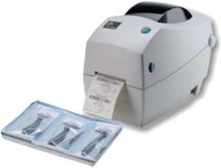
65 Accessories Cycle report printer (S'Print ( S'Print) - part n S'Print is a compact, reliable and easy-to-use printer that can be connected directly to the serial port located in the rear of the sterilizer, or via the Multiport (optional PC/logger, see next page). S'Print can be easily managed from the sterilizer control panel (See Chapter 5 - Programming) in order to: - Print cycle data reports (see Appendix 8 Example of a cycle data report ) at the end of each cycle either in automatic or manual print mode; - Print a report of any cycle stored in the sterilizer memory. Printouts are very durable and can be stored in the file records for years. Label printer (LisaSafe ( LisaSafe) - part n (with bar code reader), (without bar code reader) LisaSafe is a fast label printer that can be connected directly to the serial port located in rear of the sterilizer, or via the Multiport (optional PC/logger, see next page). LisaSafe prints self-adhesive permanent paper labels to be attached to pouches, showing: -either the main information of the cycle and the sterile load (cycle number and type, date, time, expiry date); - or the sterilization lot number. LisaSafe is conceived to be the heart of the traceability system in the dental practice, permitting a safe and easy management of the stock of sterilized tools and instruments. LisaSafe is also compatible with the W&H sterilizers series 300, 500 and 500 Fully Automatic. All the label printer functions can be easily controlled from the sterilizer control panel (See Chapter 5 - Programming) in order to: - Print a selected number of labels at the end of the cycle, either in automatic or manual print mode; - Print extra labels of the most recent cycle; - Print labels of any cycle stored in the sterilizer memory. 65
66 Accessories Multiport (PC/logger) - part n Multiport is an intelligent hub device that connects to the sterilizer rear serial port and allows managing a variety of optional endorsed devices (see connection schemes on the following pages). Multiport supports/features: -The cycle report printer S'Print (see description on the previous page); - The label printer LisaSafe (see description on the previous page); - A port for sending cycle data to a PC/network for data storage; - A USB port to attach a USB storage memory device (included in the product package) for data storage without using a PC. Water feed system - part n. X051110X Mount this kit in the sterilizer if you want to connect a water filtration system to automatically fill the clean water tank with demineralized water and drain the used water tank continuously. The kit needs to be mounted by an authorized service technician, or by the factory upon specific order request. Water quality provided by the filtration system has to comply with Appendix 7. The water supply pressure must be between 2 and 8,6 bar. Permanent drain kit - part n. X051052x This kit is mounted to continuously drain the used water tank, thus manual tank draining is no longer necessary. The kit needs to be mounted by an authorized service technician, or by the factory upon specific order request. Drain tube kit with fittings - part n. A812110X Use this kit to connect the sterilizer permanent drain to a drain pipe. 66


67 Accessory connection scheme (data communication) LisaSafe Kit LisaSafe Multiport Multiport S Print S Print 67


68 Accessory connection scheme (water treatment, supply and drain) External water filtration system Water feed system Osmo 68
69 Accessories and spare parts 190x43x300/375 * 190x43x300/375 * 190x43x300/375 * Standard chamber rack for 3 cassettes (*) LINA MB17: part n. F523008x LINA MB22: part n. F523009x 205x35x300/375 * 210x35x300/375 * 205x35x300/375 * Standard chamber rack for 3 USA size cassettes (*) LINA MB17: part n. F523020x LINA MB22: part n. F523021x 190x32x300/375 * 210x32x300/375 * 210x32x300/375 * 190x32x300/375 * Standard chamber rack for 4 cassettes (*) LINA MB17: part n. F523012x LINA MB22: part n. F523015x 190x70x300/375 * 190x70x300/375 * Standard chamber rack for 2 implant cassettes (*) LINA MB17: part n. F523016x LINA MB22: part n. F523017x (*) All racks shown in this page, if rotated 90, accept 5 standard aluminium trays. 69
70 Consumables Bacteriological filter - part n. W322400x Replace every 400 cycles Door seal - part n. F460504x Replace every 800 cycles Dust filter - part n. F364502x Replace every 400 cycles 2 x 2 x cycle consumable kit - part n. X050315x This kit consists in a stock of consumables suitable to run 800 cycles. It includes: - 1 door seal; - 2 air filters; - 2 dust filters with handle. 70
71 APPENDIX 10. Helix test documentation form Use this page to create a logbook tracing the effectiveness of the sterilization cycle during the whole lifespan of your sterilizer. Date Cycle N. Operator Released Signature Chemical indicator YES YES YES YES YES YES YES YES YES YES NO NO NO NO NO NO NO NO NO NO
72 YES YES YES YES YES YES YES YES YES YES YES YES YES YES NO NO NO NO NO NO NO NO NO NO NO NO NO NO
73 Notes
74
75 Authorized W&H service partners Find your nearest W&H service partner at Simply go to the menu option»service«for full details. Alternatively please contact: W&H UK LIMITED, 6 Stroud Wood Business Centre, Park Street, St.Albans, Herts AL2 2NJ t f technical.uk@wh.com A-DEC AUSTRALIA CO.INC., Unit 8, 5-9 Ricketty Street, Mascot NSW 2020, t f a-dec@a-dec.com.au Ivoclar Vivadent NZ, P.O.Box 5243, Wellesley Street, 12 Omega Street, Auckland, t f ivoclarvivadent@ivoclarvivadent.co.nz
, via Bolgara, 2 t +39/035/66 63 000 f +39/035/50 96 988 wh.")
76 Manufacturer W&H Sterilization S.r.l. Italy, I Brusaporto (Bg), via Bolgara, 2 t +39/035/ f +39/035/ wh.com Iso 13485, 93/42 EEC Annex II LINA MB ENG Rev. 3.1 Subject to alterations
Posizione logo. Instructions for use MS-22. MS-22 EN13060-ST55- ENG - Rev. 3
 Posizione logo Instructions for use MS-22 EN13060-ST55- ENG - Rev. 3 MS-22 Symbols Symbols displayed on the product and/or used in this manual: WARNING! Risk of injury ATTENTION! To prevent damage occurring
Operations Manual. Part Number: For Research Use Only
 Operations Manual Part Number: 470230-598 For Research Use Only Ph: 1-800-962-2660 - Web: www.wardsci.com Thank you for choosing our Bench top sterilizers. Prior to operating this instrument, please read
User Manual. Dryer Controller M720
 User Manual Dryer Controller M720 Hardware version 1.00 Software version 1.00 Preliminary version Manual M720 Dryer controller Page 1 of 42 Document history Preliminary version: - Created in April, 2009
Dryer Controller M720
 User Manual Dryer Controller M720 Hardware version 2.00 Software version 2.00 Manual M720 Dryer controller Page 1 of 60 Document history Preliminary version: - Created in April, 2009 Hardware Version 2.00,
APPENDIX 4. Thank you for choosing the Biomega BioClave steam sterilizer. HYDRAULIC DRAWING
 Thank you for choosing the Biomega BioClave steam sterilizer. Your steam sterilizer has been CE certified and designed with durability, reliability, and safety in mind. It is your responsibility to install
G-10f/GCG-10f UPRIGHT COOLER
 G-Series Cooler G-10f/GCG-10f UPRIGHT COOLER Manual is for the following models: G-10F, G-10-F33EB GCG-10F, GCG-10-F33EB GCG-10F2, GCG-10-F233EB G-10-F33EB-HC, GCG-10-F33EB-HC GCG-10-F233EB-HC Instruction
laboratory & sterilization technology
 laboratory & sterilization technology NC 23B - NC 23S/32S BENCH TOP STEAM STERILIZERS Small steam sterilizers are widely used for the sterilization of the products used for medical purposes, e.g in general
BRAVO AUTOCLAVES. Installation Notes. BRAVO 1 Quick Start Guide SD-402 Rev. 1.0 Copyright 2012 SciCan Ltd. All rights reserved
 BRAVO AUTOCLAVES Installation Notes BRAVO 1 Quick Start Guide SD-402 Rev. 1.0 Copyright 2012 SciCan Ltd. All rights reserved For questions, technical support, service and inquires, contact: Manufactured
Instruction Manual for Electric Ovens OO757X OO986X
 Instruction Manual for Electric Ovens OO757X OO986X 1 2 DEAR CUSTOMER, We thank you and congratulate you on your choice. This new carefully designed product, manufactured with the highest quality materials,
EZ9Plus & EZ11Plus Instructions on: Operating
 EZ9Plus & EZ11Plus Instructions on: Operating Step 1 Turn the unit on by setting the rocker switch mounted on the right side of the front panel to the On position. NOTE: The EZ11Plus has an automatic pre-heating
2364 Leicester Road, P.O. Box 175, Leicester, NY Phone (585) Fax (585)
 Fax (585)") Dry Heat Sterilizers with 60 Minute Sterilization Cycle Times MODEL 3100 MODEL 2100 2364 Leicester Road, P.O. Box 175, Leicester, NY 14481 Phone (585) 382-3223 Fax (585) 382-9481 www.cpac.com December
Dry Heat Sterilizers with 60 Minute Sterilization Cycle Times MODEL 3100 MODEL 2100 2364 Leicester Road, P.O. Box 175, Leicester, NY 14481 Phone (585) 382-3223 Fax (585) 382-9481 www.cpac.com December
Tabletop 2340 EA-D Class S Autoclave 19 Litres
 Tabletop 2340 EA-D Class S Autoclave 19 Litres Save time and improve efficiency in your clinic. Sterilisation in three simple steps: 1. Select the right program 2. Close the door 3. Press the Start Button
User Manual. MELAtronic 15 EN+ Autoclave. as of software version Dear Dr.
 User Manual Autoclave MELAtronic 15 EN+ as of software version 5.15 Dear Dr. We should like to extend our thanks for the expression of trust in our company which you have displayed through the purchase
Manual v1 Page 1 of 19. Manual. Laboratory autoclave
 Manual 20.2.2015 v1 Page 1 of 19 Manual Laboratory autoclave Autoclave using steam for the treatment of material and laboratory processes e.g. sterilization, as an aid in research and development CertoClav
FULLY AUTOMATIC A/C SERVICE UNIT USE AND INSTRUCTION MANUAL
 INDEX FULLY AUTOMATIC A/C SERVICE UNIT USE AND INSTRUCTION MANUAL INDEX PARAGRAPH TITLE DESCRIPTION VERSION PAGE N. GENERAL INFO PRELIMINARY INSTRUCTIONS, PROPER USE SW 1.3.X VER.1.0 3 INSTALLATION PREPARING
FN 032/055/120 DRY HEAT STERILIZERS / OVENS FN 300/400/500 DRY HEAT STERILIZERS / OVENS KD 200/400/700 OVENS EV 018 VACUUM OVEN
 FN 032/055/120 DRY HEAT STERILIZERS / OVENS Three different sizes: 32, 55 and 120 liters. Temperature range: Ambient Temperature +5 C / 250 C. Designed for sterilization, drying and heating purposes. User
STERIDENT, STERIMAT, STERIMAT PLUS
 STERIDENT, STERIMAT, STERIMAT PLUS Compact and economic steam sterilizers designed for medical and dental departments, clinics and hospitals. Generation of small steam sterilizers protecting human health
Installation and user manual
 Installation and user manual Please read carefully and retain for future reference Models EcoHeat: C3, C5, C6, C8, C9, C11, C12 Rev.1_09-07-15 Page 1 Table of Contents 1 IMPORTANT: WARNINGS 1.1 GENERAL
TABLE TOP - STEAM STERILIZER Dental & Hospital Application
 TABLE TOP - STEAM STERILIZER Dental & Hospital Application THE CISA GROUP COMPANY COMPANY PROFILE CISA has been manufacturing and selling sterilization systems for over 60 years for both hospitals and
Tornado Operations & Maintenance Manual
 TORNADO INDUSTRIES 7401 W. LAWRENCE AVENUE CHICAGO, IL 60706 (708) 867-5100 FAX (708) 867-6968 www.tornadovac.com Tornado Operations & Maintenance Manual MODEL NO. 99690 BD 22/14, 99720 BD 26/14 L9722
MacDonald Steel Limited
 DELUXE FILLER / CROWNER MODEL - DFC4 1 REV 00 CAUTION / WARNING READ MANUAL BEFORE OPERATING MACHINE DO NOT EXCEED 50 PSI ON Co2 OR BEER LINES DO NOT EXCEED 100 F (35 C) ON Co2 OR BEER LINES DO NOT HOSE
Bravo. Troubleshooting Guide
 Bravo Troubleshooting Guide Table of Contents Table of Contents 2 Bravo Alarm Code by Alarm Code Indication 3 Alarm Codes A022, A023, A024, E020 & E021 Door Locking Problems 4-9 Alarm Code E010 10 Alarm
BSM60SS / BSM60WH BUILT IN MULTI-FUNCTION ELECTRIC FAN OVEN. Instruction Manual
 BSM60SS / BSM60WH BUILT IN MULTI-FUNCTION ELECTRIC FAN OVEN Instruction Manual Please read these instructions carefully before use and retain for future reference CONTENTS Safety Instructions 2 Specifications
CRISTAL Built-in Dish Sterilizer Instruction Manual
 CRISTAL Built-in Dish Sterilizer Instruction Manual Model No.: D36DSS Version Number: 01 Revision Date: September 2014 Dear user: Thank you for your purchase of CRISTAL built-in dish sterilizer! Please
NC SERIES. Bench Top Steam Sterilizers
 NC SERIES Bench Top Steam Sterilizers NC 23B - NC 23S/32S BENCH TOP STEAM STERILIZERS Small steam sterilizers are widely used for the sterilization of the products used for medical purposes, e.g in general
i.c³ User Guide For Helmer i.series Ultra-Low Freezers A/A
 i.c³ User Guide For Helmer i.series Ultra-Low Freezers 360175-A/A Document History Revision Date CO Supersession Revision Description A 18 APR 2014* 9275 n/a Initial release. * Date submitted or change
Class B Autoclaves Instruction for Use
 Master in Sterilization Class B Autoclaves Instruction for Use Table of Contents General Scope of Manual... 3 Intended Us... 3 General Safety Instructions... 3 Standards and Directives... 3 Symbols...
, '0''/).''$ /*'( 1'%* 00) ',))% *)) $ 3:36;$ !"## $%& '()*+,,,( '()*
.''$ /*'( 1'%* 00) ',))% *)) $ 3:36;$ !## $%& '()*+,,,( '()*") -'*.'/ 0,%,)$ *'/1', '0''/).''$23456533-7860/*'( -0''/).''10))'' $).''%0/*' 1'%* 00) ',))% *)) 0 ))))%))( 3 0''/).''0',''.$'.)%*., 0).''( 39523$ 3:36;$ 0/*'/'.''./ %.)'
-'*.'/ 0,%,)$ *'/1', '0''/).''$23456533-7860/*'( -0''/).''10))'' $).''%0/*' 1'%* 00) ',))% *)) 0 ))))%))( 3 0''/).''0',''.$'.)%*., 0).''( 39523$ 3:36;$ 0/*'/'.''./ %.)'
Enteral Pump Instructions for Use To Assemble When the low
 Enteral Pump Instructions for Use Before initial use on battery power and after extended storage periods, the pump must be plugged into an AC power source for a minimum of 12 hours (pump may be operated
CLINOCLAV steam sterilizer AH-21 L
 CLINOCLAV steam sterilizer AH-21 L AH-21 L Optional printer Advantages: Agar mode (40-80ºC) Programmable auto-start (24 h) Control software Program for liquids Connection to PC (USB) Heart probe (optional)
Operations Manual TS400. Test Station for G450/G460 Gas Detector
 TS400 Test Station for G450/G460 Gas Detector Operations Manual 1194 Oak Valley Dr, Ste 20, Ann Arbor MI 48108 USA (800) 959-0329 (734) 769-0573 www.goodforgas.com GfG Products for Increased Safety Congratulations
PERFORM Operating Document
 PERFORM Operating Document Use and Maintenance of Tuttnauer Table-Top Autoclave PC-POD-CA-006-v03 Revision History Version Reason for Revision Date 01 New POD 13-Aug-13 02 POD Section 3.1.3 and 3.2 revised
User Manual. Vacuklav 23 B+ Vacuklav 31 B+ Steam sterilizer. From software version 5.15
 User Manual Vacuklav 23 B+ Vacuklav 31 B+ Steam sterilizer From software version 5.15 EN Dear doctor, we thank you for your confidence demonstrated by the purchase of this MELAG product. As an owner-run
51AKS I S O OWNER S MANUAL
 LLOYD'S REGISTER QUALITY ASSURANCE 51AKS I S O 9 00 1 OWNER S MANUAL This manual applies to the following models Stand-alone Split 51AKS 085--- 51AKS 010--- 51AKS 185--- 51AKS 013--- 51AKS 113--- 51AKS
Protection. in un unica autoclave E10
 Euronda EN Tutte le qualità Pro System Products, che cercavi, Process, Protection in un unica autoclave E10 Much more than just an autoclave E10 Euronda Pro System Products, Process, Protection Cleaning
NC SERIES. Horizontal Steam Sterilizers
 NC SERIES Horizontal Steam Sterilizers NC 300/430/570/710 HORIZONTAL STEAM STERILIZERS Our continuous investments in research and development have enabled us to develop our horizontal steam sterilizer
TS400. Operating Manual. Test Station for Microtector II Series (G450/G460)
") Operating Manual TS400 Test Station for Microtector II Series (G450/G460) GfG GESELLSCHAFT FÜR GERÄTEBAU MBH KLÖNNESTRASSE 99 44143 DORTMUND, Germany TEL. +49 / (0)2 31 / 5 64 00 0 FAX +49 / (0)2 31 /
Operating Manual TS400 Test Station for Microtector II Series (G450/G460) GfG GESELLSCHAFT FÜR GERÄTEBAU MBH KLÖNNESTRASSE 99 44143 DORTMUND, Germany TEL. +49 / (0)2 31 / 5 64 00 0 FAX +49 / (0)2 31 /
Rapid Heat Sterilizers with 6, 8, and 12 Minute Sterilization Cycle Times
 Rapid Heat Sterilizers with 6, 8, and 12 Minute Sterilization Cycle Times USER MANUAL MODELS: COX 115V COX 220V 2364 Leicester Road, P.O. Box 175, Leicester, NY 14481 Phone (585) 382-3223 Fax (585) 382-9481
Professional sterilization systems
 Professional sterilization systems Professional sterilization systems Newmed was created to satisfy the needs of customers who demand safety, reliability and simplicity all in one sterilization instrument.
GCG-9. Instruction Manual. G-Series Cooler. Manual is for the following models: GCG-9-N13EB G-9-N13EB GCG-9-B13EB UPRIGHT COOLER
 G-Series Cooler UPRIGHT COOLER Manual is for the following models: -N13EB G-9-N13EB -B13EB Instruction Manual FOR YOUR FUTURE REFERENCE This easy-to-use manual will guide you in getting the best use of
VS LD series vertical steam sterilizers
 VS LD series vertical steam sterilizers Steelco vertical Steam Sterilizers VS LD series are designed to answer the typical sterilization needs of a laboratory: glassware, stainless steel instruments, culture
Fog 1550 FT USER MANUAL. Version: 1.2. ROBE Lighting s.r.o. Czech Republic
 Fog 1550 FT USER MANUAL Version: 1.2 ROBE Lighting s.r.o. Czech Republic www.robe.cz Fog 1550 FT Table of contents 1. Introduction 4 2. Cautions 4 3. Unpacking & Inspection 5 4. Setup 5 5. Operation 5
Operating Instructions
 Operating Instructions Clinical Autoclaves P3 - Decals, displays and controls P4 - Introduction - Key to Pictures P5 - Getting Started P6 - Continued Operation P7 - Troubleshooting P8 - Technical Specification
Operation and Maintenance Manual
 Operation and Maintenance Manual Pre/Post-vacuum Class B Table top Autoclave Model Elara11 (Bacsoft) Cat. No. MAN205-0497002EN Rev. F Manufactured by: Tuttnauer Co. Ltd., Har Tuv Industrial zone B P.O.Box
OPERATING AND MAINTENANCE MANUAL
 Enter Serial No. here. In the event of an enquiry please quote this serial number. www.monoequip.com OPERATING AND MAINTENANCE MANUAL COMPACT SERIES 644 4 TRAY OVEN FILE 98 644 compact 4 tray RevA18 11-01-18
USER MANUAL. Safety Precautions. Unit Specifications and Features. Operating Instructions. Installation Instructions.
 Safety Precautions Unit Specifications and Features Operating Instructions Installation Instructions Care and Cleaning Troubleshooting Tips USER MANUAL Dehumidifier TDDP7011ES2 Warning notices: Before
The Information Contained in this Document is Proprietary and should only be used for Service or Training of Authorized Blodgett Servicers who will
 The formation Contained in this Document is Proprietary and should only be used for Service or Training of Authorized Blodgett Servicers who will be working on the Blodgett XR8 Oven. All other uses are
OWNER S MANUAL DLFCAB / DLFCHB / DLFDAB / DLFDHB High Wall Ductless System Sizes 09 36
 OWNER S MANUAL DLFCAB / DLFCHB / DLFDAB / DLFDHB High Wall Ductless System Sizes 09 36 TABLE OF CONTENTS PAGE SAFETY PRECAUTIONS... 2 GENERAL... 2 INDOOR UNIT PART NAMES... 3 REMOTE CONTROL PART NAMES...
GCG-10. Instruction Manual. G-Series Cooler. Manual is for the following models: GCG-10-N33EB G-10-N33EB UPRIGHT COOLER
 G-Series Cooler GCG-10 UPRIGHT COOLER Manual is for the following models: GCG-10-N33EB G-10-N33EB Instruction Manual Manual is for the following models: GCG-10-N33EB G-10-N33EB Instruction Manual GCG-10
PR-L2466W- PA. Operating Instructions. High Performance Refrigerator PR-L2466W-PA
 Operating Instructions High Performance Refrigerator PR-L2466W- PA PR-L2466W-PA Please read these instructions carefully before using this product, and save this manual for future use. See page 11 for
Waters 2695 Separations Module
 S U P P L E M E N T A L R E L E A S E N O T E S Waters 2695 Separations Module Firmware Update Version 2.04 Firmware Update Version 2.04 Information This firmware update incorporates improved checking
OWNER S MANUAL. R 410A Ductless Split System Air Conditioner and Heat Pump
 R 410A Ductless Split System Air Conditioner and Heat Pump Models DLC4(A/H) Outdoor Unit, DLF4(A/H) Indoor Unit Sizes 9K, 12K, 18K, 24K, 30K and 36K Please read the operating instructions and safety precautions
FLOW CONTROLLER TYPE S/601
 Checked Version Release date QA V4.2.6 F1 F2 EN 26.01.2012 Manual FLOW CONTROL FLOW CONTROLLER TYPE S/601 MODELS F1 AND F2 INTRODUCTION Thank you for using the S/601 flow and batch control series. This
POLYMIX PX-IG 2000 Operating Instructions
 POLYMIX PX-IG 2000 Operating Instructions Voltage D 100-120V, 50/60 Hz D 210-250V, 50/60 Hz Please check that the voltage is correct and corresponds with the nameplate on the back of the machine. Manual
OT SERIES. Bench Top Steam Sterilizers
 OT SERIES Bench Top Steam Sterilizers OT 18/23B OT 23/32VS OT 23S BENCH TOP STEAM STERILIZERS Small steam sterilizers are widely used for the sterilization of the products used for medical purposes, e.g
DEKO Washer-disinfector WASHROOM SYSTEMS
 DEKO 2000 Washer-disinfector WASHROOM SYSTEMS RELIABLE PERFORMANCE The DEKO 2000 is designed and constructed to meet the performance and design requirements stated in EN ISO 15883-1 Washer-disinfectors
BSF60WH / BSF60SS BUILT IN ELECTRIC FAN OVEN. Instruction Manual. Please read these instructions carefully before use and retain for future reference
 BSF60WH / BSF60SS BUILT IN ELECTRIC FAN OVEN Instruction Manual Please read these instructions carefully before use and retain for future reference SAFETY INSTRUCTIONS Important: This appliance is not
USER MANUAL TOUCHCLAVE-LAB AUTOCLAVES
 USER MANUAL Part 1 all users TOUCHCLAVE-LAB AUTOCLAVES ADVANCED STERILIZING TECHNOLOGY LTE Scientific Ltd Greenbridge Lane, Greenfield, Oldham OL3 7EN, England Tel: +44(0)1457 876221 Fax: +44(0)1457 870131
Operations Manual TS400. Test Station for G450/G460 Gas Detector
 TS400 Test Station for G450/G460 Gas Detector Operations Manual 1194 Oak Valley Dr, Ste 20, Ann Arbor MI 48108 USA (800) 959-0329 (734) 769-0573 www.gfg-inc.com GfG Products for Increased Safety Congratulations
Technical Description. for the. Autoclave. Thank you very much for the trust which you have shown by purchasing this autoclave.
 Technical Description for the Autoclave Vacuklav 23 B Dear Doctor: Thank you very much for the trust which you have shown by purchasing this autoclave. For 50 years now, MELAG a medium-sized family-owned
STATCLAVE G4 - Chamber Autoclave
 STATCLAVE G4 - Chamber Autoclave OPERATOR S MANUAL 95-115362 CA EN R2. STATCLAVE G4 Operator s Manual, Copyright 2019 SciCan Ltd. All rights reserved. Manufacturer s Information and Customer Service Information
Marco Beverage Systems Ltd. INSTRUCTIONS FOR MODELS
 Marco Beverage Systems Ltd. INSTRUCTIONS FOR MODELS Ecoboiler UC4L 2.4kW (1000740#) Ecoboiler UC10L 2.8kW (1000741#) Ecoboiler UC10L 5.6kW (1000742#) Ecoboiler UC4L 1.5kW 110V (1000747) Ecosmart UC4L 2.4kW
Hygea Hygea Hygea
 Hygea 2 Operator InstructionManual Contents Contents... 1 Safety instructions... 2 Quick guide... 3 Operator instructions... 4 Cycle abort messages... 11 Draining the tank... 14 Changing printer paper...
Dyna-Form Air. Alternating Pressure Relief Overlay System
 Dyna-Form Air Alternating Pressure Relief Overlay System 1 Contents Introduction 3 Cleaning 10 General Warnings 4 Control Unit 10 Unpacking / Setting Up 5 Air Filter 10 Setting Up 6 Mattress Cover 11 Connect
PREMIUM LINE. DOMINA PLUS B Water Steam Sterilizer. User Manual. Rev. 8 Date: March 2017 OM1004U
 PREMIUM LINE DOMINA PLUS B Water Steam Sterilizer User Manual Rev. 8 Date: March 2017 OM1004U Domina Plus B fulfills all the directions in force concerning the safety, and the built-in parameters has been
Spa Touch Control Panel with 2000, 2100 controllers. (Spa Owner s Manual insert)
") Spa Touch Control Panel with 2000, 2100 controllers (Spa Owner s Manual insert) P.N. 7876B February 11, 2015 For Spas equipped with BP2000, BP2100 controllers and Spa Touch panel. Spa Touch Control Panel
Spa Touch Control Panel with 2000, 2100 controllers (Spa Owner s Manual insert) P.N. 7876B February 11, 2015 For Spas equipped with BP2000, BP2100 controllers and Spa Touch panel. Spa Touch Control Panel
Bravo Display Warning Messages
 Bravo Display Warning Messages The sterilizer periodically reminds the user about recommended routine maintenance operations that must be carried out in order to ensure the proper operation of the device.
OPERATING MANUAL. for the modular heat presses. Secabo TC5 SMART and TC7 SMART
 OPERATING MANUAL for the modular heat presses Secabo TC5 SMART and TC7 SMART Congratulations on the purchase of your Secabo heat press! Please read this operating manual carefully to ensure a smooth production
GCG-26c. Instruction Manual. G-Series Cooler
 G-Series Cooler UPRIGHT COOLER Manual is for the following models: GCG-26-C14N7 GCG-26-C14NG GCG-26-C14NI GCG-26-C14NM GCG-26-C14NJ GCG-26 G-26-C14N7 G-26-C14NG G-26-C14NI G-26-C14NM G-26-C14NJ G-26 Instruction
CONTROL PANEL INTERFACE ACTIVATE THE GENERATOR DISPLAY INTERFACE MENUS. Control Panel USING THE AUTO/OFF/MANUAL SWITCH
 CONTROL PANEL INTERFACE USING THE AUTO/OFF/MANUAL SWITCH With the switch set to AUTO, the engine may crank and start at any time without warning. Such automatic starting occurs when utility power source
NC 100. Vertical Steam Sterilizer
 NC 100 Vertical Steam Sterilizer NC 100 VERTICAL STEAM STERILIZER NC 100 Vertical Steam Sterilizer is designed for the sterilization of textile, wrapped or packed materials, glass and liquid in operating
AZTECA A LITRE STERILISER
 Product Description Azteca A-6615 is a fully automatic high-speed pre & post vacuum steam sterilizer. This model is an electrically heated sterilizer, which operates with saturated steam as a sterilizing
Important Safeguards. Topic 2 SAVE THESE INSTRUCTIONS - FOR HOUSEHOLD USE ONLY SAVE THESE INSTRUCTIONS - FOR HOUSEHOLD USE ONLY 3
 User s Manual Index Topic Important safeguards 03 Safety features 05 Parts and accessories 05 Before first use 06 Operating instructions 06 Programme settings 08 Care and cleaning 09 Pressure canning guide
OPERATING INSTRUCTIONS
 OPERATING INSTRUCTIONS Automatic Carousel Stainer MSM INS5000GB 2011_08_07 Instructions MSM 1 Instructions MSM 2 CONTENTS 1. INTENDED USE... 4 2. SYMBOLS... 4 3. SAFETY NOTES... 4 4. COMPONENTS... 5 5.
Grafisk Maskinfabrik A/S Bregnerødvej 92, DK-3460 Birkerød, Denmark. Website: Phone:
 IR330 Inspection Rewinder with Label Dispenser & Inkjet IR330 Operation Manual Grafisk Maskinfabrik A/S Bregnerødvej 92, DK-3460 Birkerød, Denmark. Website: www.gm.dk. E-Mail: gm@gm.dk. Phone: +45 4581
Waters 2695D Separations Module
 S U P P L E M E N T A L R E L E A S E N O T E S Waters 2695D Separations Module Firmware Update Version 2.04d Firmware Update Version 2.04d Information This firmware update incorporates improved connectivity
Spa Touch Control Panel with BP2100, BP6013 spa controllers. (Spa Owner s Manual insert)
") Spa Touch Control Panel with BP2100, BP6013 spa controllers. (Spa Owner s Manual insert) P.N. 7876C (export) February 12, 2015 For Spas equipped with BP2100, BP6013 controllers and Spa Touch panel. Spa
Spa Touch Control Panel with BP2100, BP6013 spa controllers. (Spa Owner s Manual insert) P.N. 7876C (export) February 12, 2015 For Spas equipped with BP2100, BP6013 controllers and Spa Touch panel. Spa
CENTRAL STERILISATION. Innovative, hardworking Sterilisation & Infection Control products perfect for your Central Sterile Supply Department
 CENTRAL STERILISATION Innovative, hardworking Sterilisation & Infection Control products perfect for your Central Sterile Supply Department DGM AND STERILISERS FROM 100 TO 1100 LITRES Made in Europe, DGM
wc431 Slimline Integrated Dishwasher Manual for Installation, Use and Maintenance
 wc431 Slimline Integrated Dishwasher Manual for Installation, Use and Maintenance Contents Contents... 2 Important... 3 Important Notes... 4 Recommendations... 5 Before First Use... 5 Control Panel...
LOGIC CONTROLLED DEKO 25 EASE OF USE
 DEKO 25 Washer-disinfector WASHROOM SYSTEMS DEKO 25 The DEKO 25 has been designed to bring reliability, outstanding cleaning and disinfection performance and quality into one compact and economic washerdisinfector.
GB User and maintenance manual
 GB User and maintenance manual IMPORTANT SAFETY INSTRUCTIONS These instructions shall also be available on website: docs.whirlpool.eu. YOUR SAFETY AND THAT OF OTHERS IS VERY IMPORTANT This manual and
JOVY SYSTEMS RE User Manual Rev. 1.00
 JOVY SYSTEMS RE-7550 User Manual Rev. 1.00 Index - Introduction... 3 - Copyrights and Liability disclaimer........ 3 - Specifications.. 4 - Safety/ Caution instructions....... 4 - RE-7550 hardware description......
6L PRESSURE COOKER. Instruction Manual. Model: PLA1424
 6L PRESSURE COOKER Instruction Manual Model: PLA1424 Due to ongoing product improvements, specifications and accessories may change without notice. Actual product may differ slightly to that depicted.
UL U TR LTRASONIC S ONIC SCALE ALER PIEZO MINI
 ULTRASONIC SCALER PIEZO MINI CONTENTS XI - SYMBOLS 1. INTRODUCTION 1 Alternating current Type BF device 2. WARNINGS 1 3. PRESENTATION 1 3.1 Presentation 1 3.2 Technical description 2! Warning, please refer
Suits all KPF849 models
 Kambrook - Australia Ground Floor, Suite 2, 170-180 Bourke Rd Alexandria NSW 2015, Australia Locked Bag 2000 Botany NSW 1455 Customer Service Line 1300 139 798 Customer Service Fax 1800 621 337 www.kambrook.com.au
Operating Manual. for the. Autoclave. Thank you very much for the trust which you have shown by purchasing this autoclave.
 Operating Manual for the Autoclave Euroklav 23 S Dear Doctor: Thank you very much for the trust which you have shown by purchasing this autoclave. For more than 50 years now, MELAG a medium-sized family-owned
USER MANUAL. Version: 1.0. ROBE Show Lighting s.r.o. Czech Republic
 USER MANUAL Version: 1.0 ROBE Show Lighting s.r.o. Czech Republic www.robe.cz Table of contents 1.Introduction 4 2.Cautions 4 3. Unpacking & Inspection 5 4. Setup 5 5. Operation 5 5.1.Control Module Operation
USER INSTRUCTION MANUAL. Autofill Wall Mount Boilers /12/14
 USER INSTRUCTION MANUAL Autofill Wall Mount Boilers EN 083272701-11/12/14 Contents 1.0 About your Product My Product (please complete this section) page 3 Introduction page 4 Warranty page 4 Important
AOYUE 968A+ INT. Deluxe Repairing System INSTRUCTION MANUAL
 AOYUE INT 968A+ Deluxe Repairing System INSTRUCTION MANUAL Thank you for purchasing Aoyue INT 968A+ Repairing System. It is important to read the manual before using the equipment. Please keep manual in
VF X Series. User Manual. SKOPE Vertical Freezer. MAN11137 Rev. 1.1 Sep VF650X
 VF X Series SKOPE Vertical Freezer MAN11137 Rev. 1.1 Sep. 2016 VF650X SKOPE Warranty Protection Register now for peace of mind It s quick and simple. Take a few minutes to register your SKOPE product and
VF Series. User Manual. SKOPE Vertical Freezer. MAN10521 Rev. 3.3 Jun VF1000
 VF Series SKOPE Vertical Freezer MAN10521 Rev. 3.3 Jun. 2016 VF1000 SKOPE Warranty Protection Register now for peace of mind It s quick and simple. Take a few minutes to register your SKOPE product and
OWNER'S MANUAL R-410A Duct Free Split System Air Conditioner and Heat Pump
 R-10A Duct Free Split System Air Conditioner and Heat Pump Product Family: DFF(A/H)H, DFC(A/H) Please read the operating instructions and safety precautions carefully and thoroughly before installing and
BUILT-IN OVEN MODEL: EBO-E7081D(SS) Owner s Manual Please read this manual carefully before operating your set. Retain it for future reference.
 Owner s Manual Please read this manual carefully before operating your set. Retain it for future reference.") BUILT-IN OVEN MODEL: EBO-E7081D(SS) Owner s Manual Please read this manual carefully before operating your set. Retain it for future reference. Record model number and serial number of the set. See the
BUILT-IN OVEN MODEL: EBO-E7081D(SS) Owner s Manual Please read this manual carefully before operating your set. Retain it for future reference. Record model number and serial number of the set. See the
Operating Manual. for the. Autoclave. Thank you very much for the trust which you have shown by purchasing this autoclave.
 Operating Manual for the Autoclave Euroklav 29V S Dear Doctor: Thank you very much for the trust which you have shown by purchasing this autoclave. For nearly 50 years now, MELAG a medium-sized family-owned
Instructions for use
 Instructions for use These instructions are also available on the website: www.kitchenaid.eu Important instructions for safety 4 Installation 6 Safeguarding the environment 6 Troubleshooting guide 7 After-sales
INSTRUCTIONS FOR SAFE USE INSTRUCTIONS FOR SAFE USE
 USER MANUAL INSTRUCTIONS FOR SAFE USE This appliance should only be used for domestic cleaning, as described in this user guide. Please ensure that this guide is fully understood before operating the appliance.
OPERATING AND MAINTENANCE MANUAL
 Enter Serial No. here. In the event of an enquiry please quote this serial number. www.monoequip.com OPERATING AND MAINTENANCE MANUAL COMPACT SERIES 643 3 TRAY OVEN FILE 52 643 compact 3 TRAY RevA17 10-4-17
B+N 18/23L LED. Ritter CleanTec with LED Display BB 18 + BB 23. Sterilizable Products:
 Ritter CleanTec with LED Display BB 18 + BB 23 The CleanTec is available with an 18 to 23 liter chamber size and is a stand-alone autoclave with built-in water storage tank. It works with a fractionated
EST User Manual. (Please read this manual carefully before using)
") EST-1000 Handheld Intelligent Toxic Gas Detector User Manual (Please read this manual carefully before using) ENVIRONMENTAL SENSOR TECHNOLOGY CO.INC. Contents I. Product Overview...1 II. Product Description...1
EST-1000 Handheld Intelligent Toxic Gas Detector User Manual (Please read this manual carefully before using) ENVIRONMENTAL SENSOR TECHNOLOGY CO.INC. Contents I. Product Overview...1 II. Product Description...1
Focus 4010\ Focus 4010 HT porcelain firing furnace
 INSTRUCTION MANUAL Focus 4010\ Focus 4010 HT porcelain firing furnace Warning You have available one of the most precise dental furnaces equipped with a heating muffle made by the original manufacturer