COq Convection Oven. SERIES: COQ Operation Manual
|
|
|
- Karin Ford
- 6 years ago
- Views:
Transcription


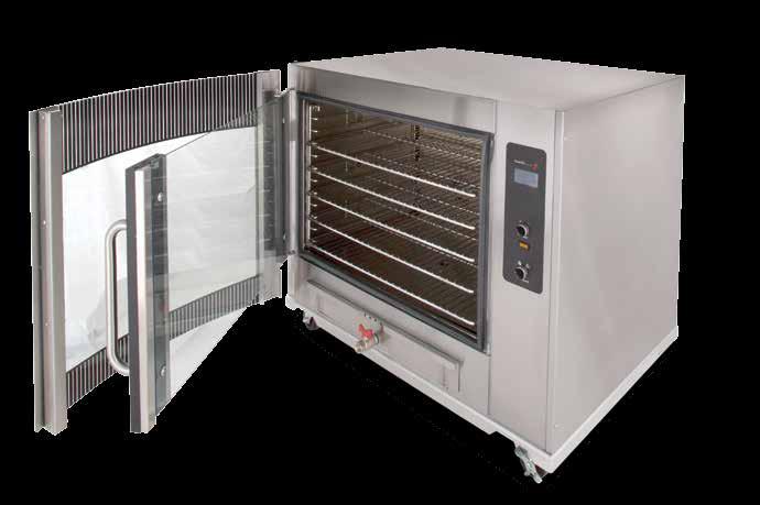

1 COq Convection Oven SERIES: COQ Operation Manual
2 BKI LIMITED WARRANTY PO Box Simpsonville, SC USA (864) Toll Free: (800) Fax: (864) WHAT IS COVERED WHO IS COVERED COVERAGE PERIOD WARRANTY COVERAGE EXCEPTIONS EXCLUSIONS INSTALLATION REPLACEMENT PARTS This warranty covers defects in material and workmanship under normal use, and applies only to the original purchaser providing that: The equipment has not been accidentally or intentionally damaged, altered or misused; The equipment is properly installed, adjusted, operated and maintained in accordance with national and local codes, and in accordance with the installation and operating instructions provided with this product. The serial number rating plate affixed to the equipment has not been defaced or removed. This warranty is extended to the original purchaser and applies only to equipment purchased for use in the U.S.A. Warranty claims must be received in writing by BKI within one (1) year from date of installation or within one (1) year and three (3) months from data of shipment from the factory, whichever comes first. COB Models: One (1) Year limited parts and labor. COM Models: Two (2) Year limited parts and labor. COM convection ovens also have a two (2) year door warranty. CO1 Models: Two (2) Year limited parts and labor. Five (5) Year limited door warranty. BevLes Products: Two (2) Year limited parts and labor. Warranty period begins the date of dealer invoice to customer or ninety (90) days after shipment date from BKI, whichever comes first. This warranty covers on-site labor, parts and reasonable travel time and travel expenses of the authorized service representative up to (100) miles round trip and (2) hours travel time and performed during regular, weekday business hours. Any exceptions must be pre-approved in advance and in writing by BKI. The extended door warranty on convection ovens years 3 through 5 is a parts only warranty and does not include labor, travel, mileage or any other charges. Negligence or acts of God, Thermostat calibrations after (30) days from equipment installation date, Air and gas adjustments, Light bulbs, Glass doors and door adjustments, Fuses, Adjustments to burner flames and cleaning of pilot burners, Tightening of screws or fasteners, Failures caused by erratic voltages or gas suppliers, Unauthorized repair by anyone other than a BKI Factory Authorized Service Center, Damage in shipment, Alteration, misuse or improper installation, Thermostats and safety valves with broken capillary tubes, Freight other than normal UPS charges, Ordinary wear and tear, Failure to follow installation and/or operating instructions, Events beyond control of the company. Leveling, as well as proper installation and check out of all new equipment - per appropriate installation and use materials is the responsibility of the dealer or installer, not the manufacturer. BKI genuine Factory OEM parts receive a (90) day materials warranty effective from the date of installation by a BKI Factory Authorized Service Center. Warranty is in lieu of all other warranties, expressed or implied, and all other obligations or liabilities on the manufacturer s part. BKI shall in no event be liable for any special, indirect or consequential damages, or in any event for damages in excess of the purchase price of the unit. The repair or replacement of proven defective parts shall constitute a fulfillment of all obligations under the terms of this warranty. BKI Worldwide, Inc. is a wholly owned subsidiary of Standex International Corporation. Asia Europe Latin America North America
3 Table of Contents Table of Contents Table of Contents...1 Introduction...2 Safety Precautions...2 Safety Signs and Messages...2 Safe Work Practices...3 Safety Decals...5 Health And Sanitation Practices...6 Food Handling...6 Storage Of Raw Meats...6 Coding Cooked Foods...6 Storage Of Prepared Foods...6 Operation...7 Controls and Indicators...7 CP0046 Basic TOUCH Tec Controller Operation...9 Basic Setup Editing...9 Cook Recipe Editing...10 Cooking...11 CP0058 Color TOUCH Tec Controller Operation...12 Features...12 Basic Setup Editing...13 USB Drive Usage...14 Controller Configuration...15 Recipe Editing...16 Cooking...17 Cooking Suggestions...18 Installation...19 Unpacking and Handling...19 Location and Clearance...19 Extraction...19 Wiring...19 General Guidelines...21 Guidelines for European Appliances...21 Operating...21 Safety Cut-Out...21 Maintenance...22 Scheduled Maintenance...22 Oven Cleaning (Daily)...22 Troubleshooting...24 Component Replacement...26 Light Bulb...26 Fuse Replacement...26 Temperature Probe...27 Pushbutton Switch Contact Blocks...27 Contactors...28 Controller...28 High Limit Thermostat...29 Fan Blade...30 Fan Motor...30 Fan Cover Micro Switch...30 Heating Elements...31 Heating Elements...32 Parts List...33 Wiring Diagrams
4 Table of Contents Introduction Congratulations! You have chosen a BKI Convection Oven that will give you many years of fine service from the original manufacturer, BKI. The BKI name assures you of the finest in design and engineering -- that it has been built with care and dedication -- using the best materials available. Attention to the operating instructions regarding proper installation, operation, and maintenance will result in long lasting dependability to insure the highest profitable return on your investment. PLEASE READ THIS ENTIRE MANUAL BEFORE OPERATING THE UNIT. If you have any questions, please contact your BKI Distributor. If they are unable to answer your questions, contact the BKI Technical Service Department, toll free: Outside the U.S., call Safety Precautions Always follow recommended safety precautions listed in this manual. Below is the safety alert symbol. When you see this symbol on your equipment, be alert to the potential for personal injury or property damage. Safety Signs and Messages The following Safety signs and messages are placed in this manual to provide instructions and identify specific areas where potential hazards exist and special precautions should be taken. Know and understand the meaning of these instructions, signs, and messages. Damage to the equipment, death or serious injury to you or other persons may result if these messages are not followed. This message indicates an imminently hazardous situation, which, if not avoided, will result in death or serious injury. This message indicates a potentially hazardous situation, which, if not avoided, could result in death or serious injury. This message indicates a potentially hazardous situation, which, if not avoided, may result in minor or moderate injury. It may also be used to alert against unsafe practices. This message is used when special information, instructions or identification are required relating to procedures, equipment, tools, capacities and other special data. 2
5 Table of Contents Safe Work Practices Wear Safe Clothing Appropriate To Your Job Always wear your insulated mitts when handling hot racks or touch any hot metal surface. If you lose or damage your mitts, you can buy new ones at your local restaurant equipment supply store or from your local BKI Distributor. Never wear loose clothing such as neckties or scarves while operating this equipment. Keep loose hair tied back or in a hair net while operating this equipment. Always wear appropriate personal protection equipment during the cleaning process to guard against possible injury from hot cleaning solution. Beware of High Voltage This equipment uses high voltage. Serious injury can occur if you or any untrained or unauthorized person installs, services, or repairs this equipment. Always use an Authorized Service agent to service your equipment. Keep this manual with the Equipment This manual is an important part of your equipment. Always keep it near for easy access. If you need to replace this manual, contact: BKI Technical Services Department P.O. Box Simpsonville, S.C Or call toll free: Outside the U.S., call Protect Children Keep children away from this equipment. Children may not understand that this equipment is dangerous for them and others. NEVER allow children to play near or operate your equipment. 3

6 Table of Contents Keep Safety Labels Clean and in Good Condition Do not remove or cover any safety labels on your equipment. Keep all safety labels clean and in good condition. Replace any damaged or missing safety labels. Refer to the Safety Labels section for illustration and location of safety labels on this unit. If you need a new safety label, obtain the number of the specific label illustrated on page 5, then contact: BKI Technical Services Department P.O. Box Simpsonville, S.C Or call toll free: Outside the U.S., call Be Prepared for Emergencies Be prepared for fires, injuries, or other emergencies. Keep a first aid kit and a fire extinguisher near the equipment. You must use a 40-pound Type BC fire extinguisher and keep it within 25 feet of your equipment. Keep emergency numbers for doctors, ambulance services, hospitals, and the fire department near your telephone. Know your responsibilities as an Employer Make certain your employees know how to operate the equipment. Make certain your employees are aware of the safety precautions on the equipment and in this manual. Make certain that you have thoroughly trained your employees about operating the equipment safely. Make certain the equipment is in proper working condition. If you make unauthorized modifications to the equipment, you will reduce the function and safety of the equipment. 4


7 Table of Contents Safety Decals N0166 N0202 OPERATOR S SIDE 5
8 Table of Contents Health And Sanitation Practices BKI ovens are manufactured to comply with health regulations and are tested and certified to UL, CUL, and NSF standards. You must operate the equipment properly using only quality products and use meat thermometers to insure meats are thoroughly cooked. Food Handling Wash hands thoroughly in warm, soapy water after handling raw poultry or meats. Clean and sanitize all utensils and surfaces that have been in contact with raw products. Never place cooked meats on the same surfaces used to prepare raw meats, unless the area has been thoroughly cleaned and sanitized. Storage Of Raw Meats Designate an area or shelf strictly for the storage of all raw meats to be used in the oven. Raw product must always be stored at temperatures below 38 F. (3 C.). Never store or mix raw foods above cooked foods, as this is a health hazard. The drippings from raw foods contaminate cooked or processed foods. All chicken and chicken parts to be stored overnight must be thoroughly iced down and refrigerated. Coding Cooked Foods All products cooked during the day should be sold the same day. NOTE: It is not the intent of the cooking program to have unsold merchandise at the end of the cooking day. Follow your company s procedures for the handling of any leftover product. Storage Of Prepared Foods Cold foods should be kept at or below 38 F. (3 C.). Hot foods must be maintained to meet local health codes, usually a minimum 145 F. (63 C.). 6
9 Operation Controls and Indicators Operation Refer to the figure and table below for an explanation of controls and indicators. TouchTEC Power 1 Fan Speed OPERATOR SIDE 7
10 Operation Item # Description Function 1 Fan Speed Switch Changes the oven fan speed between high and low. Turn switch to the desired fan speed. 2 Main Power Isolator Light This light illuminates to indicate that power is being applied to the oven from the Main Power Isolator (Circuit Breaker). 3 Main Power Switch Turns power to the entire unit on or off. When placed in the on position, the Touchscreen controller is powered and the lights illuminate. When placed in the off position, power is removed from the entire unit. 4 Analog Touchscreen Controller Used for operation and programming of the oven. A built-in beeper is used to indicate touchscreen presses and other oven functions. It has 15 programmable cooking recipes. 8
11 Operation CP0046 Basic TOUCH Tec Controller Operation Screen displays when oven main power switch is turned on. Touch anywhere on screen to activate controller. All functions of the controller are accessed from this screen. Following are instructions for - Basic Setup Editing, Cook Recipe Editing & Cooking Touching for 3 seconds turns controller Off. Use (up) and (down) arrows to highlight desired Recipe. Basic Setup Editing Start the controller and follow the procedure below to Edit the Basic Setup. Touch any highlighted Recipe for 3 seconds. COMMON SCREEN FUNCTIONS Touch to return to previous screen. Touch SAVE in any screen displayed to save edited value & return to previous screen. Use and arrows to move cursor under digit to be edited. Use and arrows to set digit value. Touch GO to enter code. (The Default Code is 0000.) Touch BASIC SETUP Touch to toggle TEMP UNITS between F and C Touch to toggle SIGNAL MODE between Short and Long beeps. Touch ACCESS CODE to edit the user Access Code. (only if you want to set code to lock programming) Touch to toggle language between English and Spanish. Use and arrows to move cursor under digit to be edited. Use and arrows to set digit value. (only if you want to set code to lock programming. The Default Code is 0000.) 9
12 Operation Cook Recipe Editing Start the controller and follow the procedure below to Edit a Cook Recipe. Touch highlighted Recipe for 3 seconds. COMMON SCREEN FUNCTIONS Touch to return to previous screen. Touch SAVE in any screen displayed to save edited value & return to previous screen. Use and arrows to move cursor under digit to be edited. Use and arrows to set digit value. Touch GO to enter code. (The Default Code is 0000.) Touch COOK PROGRAMS. Use and arrows to highlight desired Recipe. Touch EDIT to select highlighted Recipe. Use and arrows to toggle between screens. Touch any parameter to edit its value. Touching a cook segment displays the Edit Cook Segment screen below. Edit Recipe Name Edit Preheat & Hold Temps Edit Cook Segment Use and arrows to move cursor under digit to be edited. Use and arrows to set digit value. Recipe names can be maximum of 13 digits including spaces. Values available in order of display - upper case alphabet, lower case alphabet, numbers 0 thru 9 & blank space. Use and arrows to move cursor under digit to be edited. Use and arrows to set digit value. To turn Preheat or Hold OFF set temperature below 150F. Touch any parameter on this screen to edit its value. Ck Temp is the segment oven temp. Time is for the individual segment. Ct Temp is cook to temp when core temp probe used. Cook segment parameter values are edited as shown for the Preheat Temp at left. To turn a cook segment OFF, set its Ck Temp below 150 F. To turn cook to temp OFF, set the Ct Temp below 150 F. 10
13 Operation Cooking Start the controller and follow the procedure below to Cook with a programmed Recipe. COMMON SCREEN FUNCTIONS Touching for 3 seconds on any screen cancels the cook cycle & returns to the Recipe List. Touching [T] on any screen displays the actual oven temperature for 3 seconds. The small inverse H to the right of the temperature is displayed when the heating elements are energized. Touching Extra in any screen displayed activates the Extra Cook screen to add extra time to the programmed cook time. Use and arrows to adjust Extra Cook value in 5 minute increments. Touch GO to add Extra time & return to previous Recipe screen. Use and arrows to highlight desired Recipe. Touch highlighted Recipe to preview its setting. Touch GO to start highlighted Recipe. Use and arrows to toggle between screens. Touch in either screen to return to Recipe List. Touch Preheat to start heating the oven to the programmed temperature. Touch Cook to go directly the to Cook Start screen. (Preheating the oven before cooking is highly recommended.) While oven is Preheating - screen displays programmed Preheat temperature. Fan Speed Fan Speed is manually controlled with a switch on control panel below touch screen controller. Screen displays when the oven is preheated. Load product in the oven, close the door and touch COOK to start cooking. Progress bar displays percentage of total Recipe time completed. Time displayed is total remaining Recipe time. Single Segment Recipe Multi-Segment Recipe Progress bar is divided into number of Recipe segments & displays percentage of total Recipe time completed. Time displayed is total remaining Recipe time. End of Cook Cycle without Hold The controller will beep and the screen will flash until the screen is touched. The display shows the Time elapsed since the end of the Cook Cycle (no temperature is displayed). Add Extra Cook time if required or touch for 3 seconds to return to the Recipe List. End of Cook Cycle with Hold The controller will emit three 2 second beeps. The display shows programmed Hold Temperature and the Time elapsed since the end of the Cook Cycle. Add Extra Cook time if required or touch for 3 seconds to return to the Recipe List. 11
14 Operation CP0058 Color TOUCH Tec Controller Operation Features The Color TOUCHTec Controller has the following configurable features that will need to be properly set when installing a replacement controller. These settings can be entered individually through the configuration screens on the controller or downloaded from a USB drive. Temperature Display Units are configurable for Fahrenheit or Celsius. Operation Language is configurable for English or Spanish. Audible Alarm Pattern is configurable for Short or Long patterns. This function is helpful to distinguish between controllers when two controllers are used on the same appliance. View Recipe is configurable ON or OFF. When ON, a button is displayed on the Cook Recipe screen that will allow the user to view the settings of the highlighted Recipe. Power Monitor calculates the energy consumption of the appliance over the elapsed time displayed. This function can be reset to zero by the user. The energy consumption values for this appliance s components must be entered into the controller. USB Drive can be used to upload or download controller configurations and recipes. Intuitive Cook Factor is configurable for OFF or values 5-15 in 0.5 increments. If Intuitive Cook is enabled the Factor determines the amount of cook time compensation. Control Hysteresis is configurable from 1 F to 10 F by 1 F increments. Hysteresis is the differential between the temperature the controller turns the heaters off and the temperature it turns the heaters on again. Extra Time increment value is configurable to 1 minute or 5 minutes. Cook Temperature Offset is configurable between -50 F and +50 F in 1 F increments. The actual oven cavity temperature will vary from the programmed temperature by this offset amount. Door Open Alarm is configurable ON or OFF. When ON, the controller alarms if the oven cavity temperature drops 25 F indicating the door has been left open. Adjustable Idle Shutdown is configurable for OFF or 10, 20 or 30 minute delay. When enabled, this function will shut the oven off if it has been preheated and cook is not initiated before the preset time interval has elapsed. (2) RTD Temperature Probe Inputs configurable to OFF or to monitor oven Cook Temperature or internal Product Temperature. One input must be configured to monitor oven Cook Temperature. Use of the internal Product Temperature probe is optional. (2) Remote Switch Inputs configurable to OFF or to End cycle or add Extra Time when a momentary switch input is received. Both inputs can be configured OFF. (2) Relay & (1) Solid State Outputs configurable to OFF or for Heat, Fan Power, Lamp or Fan Speed control. 12
15 Operation Basic Setup Editing Turn appliance power on and follow the procedure below to Edit the Basic Setup. Press the three regions shown in green on the Cook recipe screen in sequence - Lower left, lower right, and then upper left. Maximum of two seconds between touches, valid touches emit a beep. Touch Oven Set Up. Touch X in any screen displayed to return to the previous screen. Change Code (to change current access code) opens numeric keypad window. Enter new access code and touch OK. Enter Code **** X Use numeric pad to enter 4 digit access code. Touch OK to enter code. Touch Bsp to backspace over last digit on entry line. Touch Clr to clear entry line. (The Default Code is 9999.) Bsp Ok Clr USB Drive & Factory Cfg on following pages. Touch T beside parameter. Beep: toggles between Short & Long beep patterns for end of cook cycle. Units: toggles temperature between deg Fahrenheit & deg Celsius. Lang: toggles language between English & Spanish. View: toggles View Recipe button on Cook Recipe screen ON or OFF. Touch to SAVE settings. Displays kilowatt hours of energy consumed by the appliance over elapsed Time displayed. Touch to RESET display to zero. 13
16 Operation USB Drive Usage Remove the appliance side panel & insert USB Drive into the port on the bottom of the Controller. Enter Oven Set Up screen as described on previous page. Touch X in any screen displayed to return to the previous screen. Touch USB Drive. Read a Recipe from the USB Drive: Highlight the Recipe to be read from the USB Drive to the controller and touch READ. When the download is complete and the screen displays Data Read!, touch Ok. Highlight the existing Recipe to be replaced by the Recipe saved from the USB Drive and touch SAVE. Save a Recipe to the USB Drive: Highlight the Recipe to be saved to the USB Drive and touch SAVE. When the upload is complete and the screen displays Data Saved!, touch Ok. Read a Factory Controller Configuration from the USB Drive: Highlight the Configuration to be read from the USB Drive to the controller and touch READ. Save the Factory Controller Configuration to the USB Drive: File name will be SYSCFG.BCF. Do Not change file extension. When the upload is complete and the screen displays Data Saved!, touch Ok. When the download is complete and the screen displays Data Read!, touch Ok. 14
17 Operation Controller Configuration Configure the Controller inputs and outputs for this appliance. Enter Oven Set Up screen as described previously. Touch X in any screen displayed to return to the previous screen. Touch Factory Cfg. Hyst: change control hysteresis from 1F to 10F in 1F increments. Ex T: toggles extra time increments between 1 min. and 5 min. T Off: adjusts cook temperature offset between -50F & +50F in 1F increments. D Alm: toggles 25F door alarm ON or OFF. Pre T: adjust idle shutdown time from OFF to 10, 20 or 30 min. SmCk: adjust intuitive cook factor from OFF to values 5-15 in 0.5 increments. Touch E beside parameter to open a numeric window to enter parameter value. Idle: idle power consumption. Heat: heater power consumption. Fan: fan power consumption. Touch to SAVE settings. Touch T beside parameter. P1 & P2 toggle between OFF, Cook & Product temperature. S1 & S2 toggle between OFF, End & Extra Time. Touch to SAVE settings. Touch T beside parameter. R1, R2 & D1 toggle between OFF, Heat, Fan Power, Lamp & Fan Speed. V1 toggles between OFF & Fan Speed. Touch to SAVE settings. CK: measured Cook probe temperature. PR: measured Product probe temperature. End: state of End switch. Ext: state of Extra switch. (OP=open, CL=closed) Heat: toggles Heat output ON & OFF. Lmp: toggles Lamp output ON & OFF. FanP: toggles Fan output ON & OFF. V1.10: software version (value may differ). FanS: toggles Fan Speed between HI & LO. Time: elapsed running time of controller. 15
18 Operation Recipe Editing Follow the procedure below to Edit the Cook Recipes. Enter the Main Menu screen as described on previously. Touch X in any screen displayed to return to the previous screen. Touch Edit Recipe. Enter Code **** X Use numeric pad to enter 4 digit access code. Touch OK to enter code. Touch Bsp to backspace over last digit on entry line. Touch Clr to clear entry line. (The Default Code is 9999.) Touch Recipe line to edit. Bsp Ok Clr Select a Recipe by touching the Recipe name or moving the slider bar up and down. When desired Recipe is highlighted, touch Edit. Use keypad to enter Recipe name. Sh toggles between upper & lower case. Touch Bsp to backspace over last digit on entry line. Touch Clr to clear entry line. Touch to SAVE settings. Temp: opens numeric keypad to set segment temperature. Set Hold Temp to 0 for no heat in Hold. Time: opens numeric keypad to set segment time in format X:XX. Set to 0:00 to disable a Cook segment. (Available in cook segments only.) Fan: toggles Fan Speed between HI & LO. Type: toggles between Time and Smrt (intuitive cooking). All cook segments are changed to selected type. (Not available in Preheat & Hold segments.) 16
19 Operation Cooking Follow the procedure below to Cook with a programmed Recipe. Touch X in Recipe screen to cancel Cooking Recipe. Touch Yes to confirm cancellation and return to The Cook Recipe Screen Touch No to continue Cooking Recipe. Touch X in any screen displayed to return to the previous screen. Select a Recipe by touching the Recipe name or moving the slider bar up and down. When desired Recipe is highlighted - touch Cook to start cook or touch V to View Recipe (if View Recipe is enabled). Recipe Segments & Status - Completed, Current, Future PH=Preheat; C1,C2 & C3= Cook Segment; HD = Hold (C2 & C3 only shown when enabled.) Temp: programmed segment temperature. View Recipe H displayed when heaters are energized. If Hold temperature is 0, Off is displayed in Hold mode. 250F, HI fan speed. 350F for 1 hour 10 minutes, HI fan speed, by Temperature (T changes to S with intuitive cook enabled). 250F, HI fan speed. Fan: segment fan speed setting. Time: remaining in segment. Progress Bar green displays the percentage of segment time elapsed. In Preheat, displays approach to set point from room temperature. Display Temperature Recipe02 X Add Cook Time Displays actual oven cavity temperature. If Cook to Internal Temperature is enabled, touch Cook Temp title bar to change display to actual product core temperature. Touch X to return to the Recipe screen. PH C1 HD Add Temp: Fan: Cook 350F 100 Time? H Fan: Time: 100 0:45 5 Min No Time: 0:45 Only available in Hold mode. Touch No to cancel Add Cook Time function. Each touch of 5 Min adds one 5 minute increment of Cook Time. When Cook Time is added, No changes to Done. Touch Done to start extra time cook. 17
20 Operation Cooking Suggestions Most recipes can be adjusted for convection oven use by decreasing the temperature by 25 F and decreasing cooking time about 25%. Dishes with cooking times over 45 minutes and that might dry out too much (like lasagna, or meatloaf) should be covered for the first half of the cooking time. 18

21 Installation Installation Serious injury, equipment damage or death could result if attempting to install this oven yourself. Ensure that an authorized BKI service agent install the oven. Unpacking and Handling It is the owners responsibility to file all freight claims with the delivering truck line. Inspect all cartons and crates for damage as soon as they arrive. If damage to cartons or crates is found, or if a shortage is found, note this on the bill of lading (all copies) prior to signing. If damage is found when the equipment is opened, immediately call the delivering truck line and follow up the call with a written report indicating concealed damage to your shipment. Ask for an immediate inspection of your concealed damage item. Packaging material MUST be retained to show the inspector from the truck line. Remove all packing from the interior and exterior of the oven. Location and Clearance The oven must be mounted on a level surface capable of supporting the fully loaded oven. Refer to Chart 1 for oven weight. Adequate clearance must be provided around the oven for safety, proper operation and ventilation. Refer to Chart 1 for required minimum clearances. Note that these are minimum clearances. If the oven is to be permanently mounted near other immovable objects additional clearance must be provided for connection and service of the oven on both sides. All ventilation slots must be kept free from obstruction. Extraction Extraction is not a specific requirement for this type of appliance. Certain conditions, e.g./ installation in a confined space, temperature controlled environment, continuous use or high volume production cooking may require the need for extra ventilation or extraction. Consult your local ventilation/extraction air conditioning company. Wiring Electrocution, equipment failure or property damage could result if an unlicensed electrician performs the electrical installation. Ensure that a licensed electrician perform the electrical installation. Failure to restrain the oven when permanently connected could allow it to move, possibly resulting in electrical shock. Attach an ANSI Z21.69A compliant restraining device (such as BKI part number FT0279) according to the instructions provided by the restraining device manufacturer in the location shown at right. Chart 1. Location and Clearance 19
22 Installation Electrical Specifications (North America) 3Ph + Gnd, 60Hz Volts Amps KW Breaker * 10.2* 40* * 9.3* 35* * 11.1* 35* * Ratings COq oven cavity. VGG/COq requires a separate power supply for each oven cavity. Electrical Specifications (Europe) 230/400 Volts, 3Ph + Gnd + E, 50Hz Model Amps Watts L L L Model COq VGG/COq Minimum Clearance Shipping Combustible Surface Non-Combustible Surface Height Weight A B C A B C mm 259 KG mm mm mm 51.0 mm 51.0 mm 51.0 mm 33 1/2 in. 570 lb. 6 in. 6 in. 6 in. 2 in. 2 in. 2 in mm 453 KG mm mm mm 51.0 mm 51.0 mm 51.0 mm 73 1/16 in lb. 6 in. 6 in. 6 in. 2 in. 2 in. 2 in. 20
23 Installation General Guidelines In the absence of local codes refer to the latest edition of one of the following: National Electrical Code, ANSI/NFPA 70-20XX (USA) which can be obtained from: The National Fire Protection Association Batterymarch Park Quincy, MA I.E.E. Wiring Regulations (Europe) Verify that the power supply conforms to the electrical rating listed on the oven data plate. Ensure that the appliance is grounded (earthed). Guidelines for European Appliances Note: - A method of disconnection from the main supply having a contact separation of least 3mm in all poles must be incorporated in the fixed wiring. It is recommended that an R.C.D. with a 30ma trip and contact rating to suit the appliance current be installed adjacent to the appliance. Type C/ 3 circuit breakers or appropriate rated fuses are recommended for installation at the supply end. Note: - surge currents are present when this appliance is switched on from cold. Industrial plugs and sockets must comply with BS 4343/EN60309 (IEC309.2/CEE17). Supply Cable Connection It is recommended that the power supply cable shall be an oil resistance sheathed flexible cable to BS 6007 (code designation HO7 RN-F). It is required that the power supply cable connection to the appliance terminal block, the earth conductor is to be made at least 50mm longer than the length of the live (L) and neutral (N) conductors so that if the supply cable is strained the earth conductor is the last to become disconnected. To gain access to the control panel and mains block connection, remove the 4-side panel securing screws on the drive side of the oven. The mains block is sited toward the bottom right hand side of the control box. Cable entry is provided through the base of the oven. Refer to the mains wiring diagram for correct connection. Operating Please read the operating instructions thoroughly and ensure all packaging has been removed before switching main power On. IMPORTANT: Ensure that whoever is operating this appliance is fully conversant with its working and is made aware of the dangers of incorrect operation. Safety Cut-Out For added safety all COq ovens have a built in thermal cut-out to protect against over-heating through component failure or incorrect use. If for any reason the thermal cut-out operates, the oven will automatically shut down and should be switched Off, disconnected from the mains and allowed to cool. NOTE: - The thermal cut-out will not re-set automatically. The oven must not be re-used until a qualified electrician or BKI service agent has checked it. 21
24 Maintenance Maintenance Failure to comply with the maintenance below could result in a serious accident or equipment damage. Failure to remove power from this unit before performing maintenance may cause severe electrical shock. This unit may have more than one disconnect switch. Scheduled Maintenance Oven Cleaning (Daily) Cleaning is not only necessary for sanitary reasons, but will increase sales appeal and maximize operating efficiency. Failure to remove power from this unit may cause severe electrical shock. This unit may have more than one disconnect switch. Using abrasive cleaners may damage the oven finish. Use only a mild soap and water solution. Never steam clean or get excess water in the interior of the oven as this can damage unit. This appliance is not designed for use with a water jet. DO NOT USE OVEN CLEANER on this machine. Caustic cleaners can cause damage to the machine. Always wear appropriate personal protection equipment during the cleaning process to guard against possible injury from hot cleaning solution. 1. Allow oven to cool below 50 o C (120 o F). 2. Turn the Main Power Switch off and disconnect from the Main Power Isolator (Circuit Breaker). 3. On oven so equipped, empty the grease drawer using the drain valve or fat pump. 4. Remove all food products from the unit. 5. Remove oven racks by lifting up on the front and pulling the racks out of the oven. Remove the rack side supports by lifting them up and away from the sides of the oven cavity. Remove drip tray (if so equipped). 6. Remove the fan cover in the back of the oven cavity by a. removing the (2) retaining nut in the center of the fan cover or b. Unlatch the ¼ turn fasteners on each corner of the cover by turning them counterclockwise then pull the fan cover straight out of the oven cavity. 22
25 Maintenance 7. Place all of the components removed in a large sink to soak in hot cleaning solution. Then clean the components with warm water, a sponge and BKI approved cleaner. Wipe dry with a clean cloth. 8. Clean the inside of the oven cavity with warm water, a sponge and BKI approved cleaner. Wipe dry with a clean cloth. 9. Carefully clean the fan blades in the back of the oven with warm water, a sponge and BKI approved cleaner. Be careful not to bend the blades. 10. Clean the outside of the oven with warm water, a sponge and BKI approved cleaner. Wipe the unit dry with a soft cloth. 11. Reassemble the oven. 23
26 Maintenance Troubleshooting Refer to the table below for troubleshooting information. Problem Indication Cause Possible Solution Main Power Switch On does not start oven, the control screen does not energize. Main Power Indicator Light is not lit. Appliance circuit breaker (isolator) is turned off or tripped. Call qualified electrician. Verify power supply to panel & reset breaker (isolator). Main Power Indicator Light is not lit. Controller Fuse is blown. Call BKI service technician. Identify & resolve cause of blown fuse, replace fuse. High Limit Thermostat tripped or defective. Call BKI service technician. Tripped - identify & resolve cause. Defective - replace thermostat. Defective R1 Relay. Call BKI service technician. Replace relay. None of the lights illuminate when controller screen is touched to activate oven. Light circuit Fuse is blown. Call BKI service technician. Identify & resolve cause of blown fuse, replace fuse. Not all lights illuminate when controller screen is touched to activate oven. Failed Light Bulb(s). Call BKI service technician. Replace light bulb(s). Fans & Heating Elements do not start when Preheat is touched on controller screen. Inner Door completely closed. Inner Door not (completely) closed. Failed Inner Door Magnetic Sensor. Close door, make certain magnetic latch on handle side of door contacts face of oven. Call BKI service technician. Replace magnetic sensor. With Optional Dripping Drawer & Fan Cover Switches. Dripping Drawer not (completely) installed, Fan Cover not (properly) installed. Push dripping drawer fully into oven, verify Fan Cover retainers are fully tightened. Inner Door is closed and Dripping Drawer & Fan Cover properly installed. Failed Inner Door Magnetic Sensor. Failed Dripping Drawer Switch. Call BKI service technician. Troubleshoot switches & sensor, replace failed component. Failed Fan Cover Switch. Fans start but Heating Elements do not heat when Preheat is touched on screen. Failed R2 relay. Defective Controller output. Call BKI service technician. Troubleshoot cause & replace defective component. 24
27 Maintenance Problem Indication Cause Possible Solution Heating Elements heat but Fans do not start when Preheat is touched on screen. High Limit Thermostat will trip if condition goes undetected. Failed R5 relay. Defective Controller output. Call BKI service technician. Troubleshoot cause & replace defective component. Oven Preheats slowly or does not achieve preheat temperature Failed Heating Element. Failed Fan Motor(s). Blocked air ports in Temperature Probe. Call BKI service technician. Troubleshoot cause & replace defective component. Fans & Heating Elements do not restart after oven is loaded & Cook is touched on screen. Inner Door not (completely) closed. Close door, make certain magnetic latch on handle side of door contacts face of oven. Inner Door completely closed. Failed Inner Door Magnetic Sensor. Call BKI service technician. Replace magnetic sensor. Oven shuts down during Preheat or Cook cycle, Main Power Indicator is lit. High Limit Thermostat(s) tripped. Call BKI service technician. Identify & resolve cause of trip (failed fan motor), reset thermostat(s) Product not done at end of cook cycle, poor product color. Failed Heating Element. Failed Fan Motor(s). Failed Relay (R2, R4 or R5). Call BKI service technician. Troubleshoot cause & replace defective component. Product overcooked at end of cook cycle, dark product color. Blocked air ports in Temperature Probe. Call BKI service technician. Replace defective component. Fan Motor(s) stop during Preheat or Cook cycles. Ventilation slots in back obstructed. Clear obstruction(s). Cooling Fan(s) failed. Call BKI service technician. Replace cooling fan(s). 25
28 Component Replacement Light Bulb Component Replacement 1. Disconnect the oven power supply by turning OFF the circuit breaker in the power supply service panel. 2. Remove appropriate side panel from oven. 3. Identify lampholder with failed light bulb. 4. Loosen but do not remove the lampholder mounting screw closest to the center frame of the oven. While holding the lampholder remove the other mounting screw. 5. Move the lampholder to the side away from the remaining mounting screw then pull the lampholder away from the oven. 6. Unscrew the failed light bulb from inside of the lampholder and replace with a new bulb. 7. Reinstall the lampholder on oven then replace side panel. 8. Turn the power supply to the oven ON. Fuse Replacement 1. Disconnect the oven power supply by turning OFF the circuit breaker in the power supply service panel. 2. Remove the side panel from the control side of the oven. 3. Remove the fuse from the fuseholder by inserting a 1/8 [3 mm] flat screwdriver into the slot in the fuseholder cap. While pushing in turn the screwdriver approximately ¼ turn counterclockwise. Remove the screwdriver The fuse and cap can be pulled out of the fuseholder. 4. Check the fuse for continuity with an Ohm meter. 5. If the fuse is blown, locate and correct the cause of the fuse failure before replacing the fuse. 6. Replace blown fuse with the factory specified fuse only. Contact the BKI Technical Service Department for the correct fuse. 7. Reinstall the fuse in the fuseholder by reversing the procedure in step Reattach the side panel to the oven and turn the power supply to the oven ON. 26
29 Component Replacement Temperature Probe 1. Disconnect the oven power supply by turning OFF the circuit breaker in the power supply service panel. 2. Remove the side panel from the control side of the oven. 3. Loosen probe clamp retaining screw and slide probe out of clamp. 4. Remove probe wires from the connector by inserting a 1/8 [3 mm] flat screwdriver into the release slots as shown. Insert wires from the replacement probe into the connector in the same manner. Probe is not polarized so it does not matter which color wire is inserted into the connector sections. 5. Insert the replacement probe into the clamp. The replacement probe must protrude into the cavity 5/8 [16 mm] as shown. Tighten the retaining screw. Neatly coil the excess lead length from the probe and tie wrap it so it does not contact other oven components. 6. Reattach the side panel to the oven and turn the power supply to the oven ON. Pushbutton Switch Contact Blocks 1. Disconnect the oven power supply by turning OFF the circuit breaker in the power supply service panel. 2. Remove the side panel from the control side of the oven. 3. Release the contact block mount from the pushbutton operator by depressing the release cam. 4. Move the contact block(s) and mount to an accessible position. Loosen the terminal retaining screws and remove the wires from the contact block. 5. Remove contact block from mount by inserting a flat screwdriver into the retaining clip on one side of the contact block and prying up. 6. Snap replacement contact block into place on the mount. Connect wires to replacement contact block. 7. Slide contact block mount back into position on the pushbutton operator. Push the contact block mount in until it snaps into place. 8. Reattach the side panel to the oven and turn the power supply to the oven ON. 27
30 Component Replacement Contactors 1. Disconnect the oven power supply by turning OFF the circuit breaker in the power supply service panel. 2. Remove the side panel from the control side of the oven. 3. Loosen Contactor terminal screws and remove wires from Contactor. Record the Contactor wiring connections before removing the wires. 4. The Contactor is mounted on a rail attached to the control panel. A release tab is located on the bottom of the Contactor base. To remove the Contactor, insert a flat screwdriver into the release tab and pull the tab away from the Contactor. While the release is pulled out rock that side of the Contactor up then move it toward the control board and lift it out of the control panel. 5. Install the replacement Contactor in the same orientation as the original. Tilt the side of the Contactor with the release tab up slightly and position the Contactor over the mounting rail. Engage the low side of the Contactor base on the mounting rail then rock the high side down until the release tab snaps in place on the rail. 6. Attach the wires to the replacement Contactor. Be sure to tighten the terminal screws as specified on the Contactor. 7. Reattach the side panel to the oven and turn the power supply to the oven ON. Controller 1. Disconnect the oven power supply by turning OFF the circuit breaker in the power supply service panel. 2. Remove the side panel from the control side of the oven. 3. Unplug connectors from the Controller by pulling straight out on the connector. 4. Remove the (4) retaining nuts using a 5/16 nut driver and remove the failed Controller. 5. Install the replacement Controller over mounting studs in the same orientation as the original. Reinstall and tighten the (4) retaining nuts. 6. CP0046 CONTROLLER - Set dip switch on replacement Controller as shown at right. 7. Plug all connectors into replacement Controller. 8. Reattach the side panel to the oven and turn the power supply to the oven ON. 9. Turn oven On and configure replacement controller as required. Refer to the Operation section of this manual fro instructions. 28
31 Component Replacement High Limit Thermostat 1. Disconnect the oven power supply by turning OFF the circuit breaker in the power supply service panel. 2. Remove the Back Panel and Fan Cover from the oven. 3. Remove the Clamp securing the excess capillary of the failed Thermostat on the back of the oven. Then remove the Nut from the Thermostat stem with a 12 mm wrench. 4. Loosen the Nut on the capillary retaining Screw from the outside of the oven. Place a piece of tape over the head of the capillary retaining Screw on the inside of the oven then remove the Nut from the outside. Remove the tape and capillary retaining Screw from inside of the oven. 5. Remove the (2) Screws securing the thermostat capillary bulb Mounts. 6. Carefully slide the capillary bulb out of the holes in the Mounts. Feed the Thermostat capillary and bulb through the large portion of the capillary keyhole in the back of the oven. 7. Mount the replacement Thermostat on the back of the oven with the nut provided. Orient replacement Thermostat in the same orientation as the original. Secure nut on Thermostat stem with 12 mm wrench. 8. Insert the bulb and capillary of the replacement Thermostat into the oven from the back through the large portion of the capillary keyhole in the oven back. 9. Insert the Thermostat bulb and capillary into the Mounts on the Heating Element. Be careful not to kink or pinch the capillary tube. 10. Secure the thermostat bulb Mounts to their standoffs with the two phillips Screws. 11. Carefully slide the excess Thermostat capillary through the keyhole in the oven back. Move the capillary into the smaller portion of the keyhole and insert the retaining Screw into the larger portion. 12. Place a piece of tape over the head of the capillary retaining Screw inside of the oven. Thread the Nut onto the capillary retaining Screw from the back of the oven. Remove the tape from the head of the capillary retaining screw and tighten the Screw. 13. Carefully coil the excess capillary on the back of the oven and secure it with the Clamp and Screw. Do not bend the capillary in a radius smaller than ½ [12 mm]. 14. Reattach the back panel and fan cover to the oven and turn the power supply to the oven ON. 29
32 Component Replacement Fan Blade Fan Motor 1. Disconnect the oven power supply by turning OFF the circuit breaker in the power supply service panel. 2. Remove the fan cover from the oven. 3. Loosen the set screw on the Fan Blade hub with a 1/8 hex wrench and pull Fan Blade off of Motor shaft. 4. Slide new Fan Blade onto Motor shaft. Space the back of the Fan Blade 1/4-3/8 [6-9 mm] from back wall of cavity. 5. Orient set screw in Fan Blade hub over the flat on the Motor shaft and tighten set screw with 1/8 hex wrench. 6. Spin the Fan Blade by hand to make sure it is properly balanced on Motor shaft. 7. Reattach Fan Cover and turn the power supply to the oven ON. 1. Disconnect the oven power supply by turning OFF the circuit breaker in the power supply service panel. 2. Remove the back panel and fan cover from the oven. 3. Remove the Fan Blade from the Motor as described above. 4. From the back of the oven, unplug the wiring connections to the Motor. Remove the (3) retaining nuts with an 11/32 hex driver. Pull Motor straight out from the back to remove it. 5. Install replacement Motor on back of oven over the mounting studs and secure with the (3) nuts. 6. Connect the wiring to the Motor as detailed in the diagram on the next page. 7. The orientation of the yellow and orange wires in the Motor connector establishes the direction of shaft rotation. Note orientation of yellow and orange wires in the Motor connector. Compare this orientation to the diagram on the next page. If necessary, unplug connector, rotate one side 180 degrees and plug the halves back together to achieve proper orientation. 8. Reattach the Fan Blade as described above. 9. Reattach the back panel and fan cover to the oven and turn the power supply to the oven ON. Fan Cover Micro Switch 1. Disconnect the oven power supply by turning OFF the circuit breaker in the power supply service panel. 2. Remove the back panel from the oven. 3. Disconnect the wires from the Switch and remove Switch using a Phillips screwdriver and ¼ wrench. 4. Install replacement Switch in the same orientation as the Switch that was removed. 5. Connect the wires to the COM and NO terminals of the Switch. 6. Verify that the Switch contacts change state when the Fan Cover is removed and installed. If necessary, bend the Switch actuator arm as required for proper operation. 7. Reattach the back panel to the oven and turn the power supply to the oven ON. 30
33 Component Replacement Rotation Rotation Rotation Rotation MOTOR & HEATING ELEMENT CONNECTION DIGRAM 31
34 Component Replacement Heating Elements 1. Disconnect the oven power supply by turning OFF the circuit breaker in the power supply service panel. 2. Remove the back panel and fan cover from the oven. 3. Disconnect the wires on the failed Heating Element from the back of the oven. Remove the (2) screws mounting the failed Heating Element from inside the oven. 4. Carefully pull the failed Heating Element away from the back of the oven. 5. Slide a new Gasket over the terminal ends of the Heating Element and set the replacement Heating Element in position in the oven. 6. Secure the Heating Element to the back of the oven with the two mounting screws. 7. Connect the wires to the replacement Heating Element from the back of the oven. Refer to the diagram on the previous page for proper connection. 8. Reattach the back panel and fan cover to the oven and turn the power supply to the oven ON. 32
Fried Food Warmers Series. Series: FW Operation Manual
 Fried Food Warmers Series Series: FW Operation Manual BKI LIMITED WARRANTY 2812 Grandview Dr. Simpsonville, SC 29680 USA (864) 963-3471 Toll Free: (800) 927-6887 Fax: (864) 963-5316 WHAT IS COVERED WHO
Mobile Hot Food Merchandiser Series. Series: MHB Operation Manual
 Mobile Hot Food Merchandiser Series Series: MHB Operation Manual BKI LIMITED WARRANTY Grandview Drive Simpsonville, SC 0 USA () - Toll Free: (00) - Fax: () - WHAT IS COVERED WHO IS COVERED COVERAGE PERIOD
Countertop Rotisserie Oven Series. SERIES: DR Operation Manual
 Countertop Rotisserie Oven Series SERIES: DR Operation Manual BKI LIMITED WARRANTY 2812 Grandview Dr. Simpsonville, SC 29680 USA (864) 963-3471 Toll Free: (800) 927-6887 Fax: (864) 963-5316 WHAT IS COVERED
Ventless Hoods For Rotisseries. SERIES: VGH Operation Manual
 Ventless Hoods For Rotisseries SERIES: VGH Operation Manual BKI LIMITED WARRANTY 2812 Grandview Dr. Simpsonville, SC 29680 USA (864) 963-3471 Toll Free: (800) 927-6887 Fax: (864) 963-5316 WHAT IS COVERED
COq Convection Oven. SERIES: COQ Operation Manual
 COq Convection Oven SERIES: COQ Operation Manual BKI LIMITED WARRANTY 2812 Grandview Dr. Simpsonville, SC 29680 USA (864) 963-3471 Toll Free: (800) 927-6887 Fax: (864) 963-5316 WHAT IS COVERED WHO IS COVERED
Shown with the optional VGH-8 ventless hood. Rotisserie and Convection Oven Combination. SERIES: VGG-8-COQ Operation Manual
 Shown with the optional VGH-8 ventless hood Rotisserie and Convection Oven Combination SERIES: VGG-8-COQ Operation Manual BKI LIMITED WARRANTY 2812 Grandview Drive, Simpsonville, SC 29680 (864) 963-3471
Multi - Shelf Merchandiser Series. Series: HSS Operation & Service Manual
 Multi - Shelf Merchandiser Series Series: HSS Operation & Service Manual WHAT IS COVERED WHO IS COVERED COVERAGE PERIOD WARRANTY COVERAGE EXCEPTIONS EXCLUSIONS INSTALLATION BKI LIMITED WARRANTY 2812 Grandview
Large All-Purpose Fryer Series. SERIES: DNF Operation Manual
 Large All-Purpose Fryer Series SERIES: DNF Operation Manual BKI LIMITED WARRANTY 2812 Grandview Dr. Simpsonville, SC 29680 USA (864) 963-3471 Toll Free: (800) 927-6887 Fax: (864) 963-5316 WHAT IS COVERED
OPERATIONS MAINTENANCE MANUAL
 OPERATIONS MAINTENANCE MANUAL COOK & HOLD OVEN SYSTEMS WITTCO MODEL NUMBERS 1300-AD-SS 1300-AD-SS-SPLIT LIMITED WARRANTY Wittco warrants the Products that it manufactures to be free from defects in materials
Henny Penny Island Warmer Model HMI-103 Model HMI-105 TECHNICAL MANUAL
 Henny Penny Island Warmer Model HMI-103 Model HMI-105 TECHNICAL MANUAL THIS PAGE INTENTIONALLY LEFT BLANK. Section TABLE OF CONTENTS Page Section 1. TROUBLESHOOTING... 1-1 1-1. Introduction... 1-1 1-2.
Henny Penny Island Warmer Model HMI-103 Model HMI-105 TECHNICAL MANUAL
 Henny Penny Island Warmer Model HMI-103 Model HMI-105 TECHNICAL MANUAL Section TABLE OF CONTENTS Page Section 1. TROUBLESHOOTING... 1-1 1-1. Introduction... 1-1 1-2. Safety... 1-1 1-3. Troubleshooting...
Installation and Operation Manual. 445 Procedures Cart. Page 3. Page 5. Page 8. Page 10. Important Information Page 2. Installation.
 Important Information Page 2 Installation and Operation Manual 445 Procedures Cart Installation Page 3 Description Page 5 Components Overview Page 6 Controls & Indicators Page 7 Operation Page 8 HOT Operator
e Bath Fan with Light User s Guide
 e Bath Fan with Light User s Guide abfl100rnl, BFL125RNL Item Stock Number(s): BFL100RNL, BFL125RNL IMPORTANT INSTRUCTIONS - OPERATING MANUAL READ AND SAVE THESE INSTRUCTIONS READ CAREFULLY BEFORE ATTEMPTING
OWNER'S MANUAL. FRY Holding Unit (FHU) MODELS FHU1 FHU2. Duke Manufacturing Company
 MODELS FHU1 FHU2. Duke Manufacturing Company") OWNER'S MANUAL FRY Holding Unit (FHU) Patent(s) Pending MODELS FHU FHU IMPORTANT INFORMATION, READ BEFORE USE. PLEASE SAVE THESE INSTRUCTIONS. This manual is Copyright 04 Duke Manufacturing Company. All
OWNER'S MANUAL FRY Holding Unit (FHU) Patent(s) Pending MODELS FHU FHU IMPORTANT INFORMATION, READ BEFORE USE. PLEASE SAVE THESE INSTRUCTIONS. This manual is Copyright 04 Duke Manufacturing Company. All
e Bath Fan with Light User s Guide
 e Bath Fan with Light User s Guide abfl125rok Item Stock Number(s): BFL125ROK IMPORTANT INSTRUCTIONS - OPERATING MANUAL READ AND SAVE THESE INSTRUCTIONS READ CAREFULLY BEFORE ATTEMPTING TO ASSEMBLE, INSTALL,
Extra-Large Electric Auto-Lift Fryer. SERIES: BLF Operation Manual
 Extra-Large Electric Auto-Lift Fryer SERIES: BLF Operation Manual BKI LIMITED WARRANTY 2812 Grandview Dr. Simpsonville, SC 29680 USA (864) 963-3471 Toll Free: (800) 927-6887 Fax: (864) 963-5316 WHAT IS
e Bath Fan with Light User s Guide
 e Bath Fan with Light User s Guide abfl50uq, BFL60UQ, BFL70, BFL85 Item Stock Number(s): BFL50UQ, BFL60UQ, BFL70, BFL85 IMPORTANT INSTRUCTIONS - OPERATING MANUAL READ AND SAVE THESE INSTRUCTIONS READ CAREFULLY
AHPO-6/18 GOLD PROOFER OVEN
 AHPO-6/18 GOLD PROOFER OVEN For information or technical assistance, call: TOLL FREE 1(800) 735-DUKE (3853) or 1(314) 231-1130 PN 156081R 1 of 25 TABLE OF CONTENTS MANUFACTURER S INTRODUCTION...3 INSTALLATION...4
InstructIon Manual KrEs EQuIPMEnt stands
 Instruction Manual Instruction Manual SELF-CONTAINED AND REMOTE Kairak KRES model refrigerated equipment stand units are available in many lengths from 36 to 120 inches long. These units are available
Instruction Manual. Double Candy Apple Cooker
 Instruction Manual Double Candy Apple Cooker Model No. 4416 10700 Medallion Drive, Cincinnati, Ohio 45241-4807 USA 2014 Gold Medal Products Co. Part No. 46841 SAFETY PRECAUTIONS DANGER Machine must be
BLG-HGP Model Bottom Mounted Full-Length Swing Glass Door Freezer Merchandisers
 Installation & Operations Manual for BLG-HGP Model Bottom Mounted Full-Length Swing Glass Door Freezer Merchandisers 2 TABLE OF CONTENTS INTRODUCTION..... 4 STORE CONDITIONS........ 4 WARNING LABELS AND
Installation & Operations Manual for R-290 SERIES. BMG-HGP Model Bottom Mounted Full-Length Swing Glass Door Refrigerator Merchandisers 2/
 Installation & Operations Manual for R-290 SERIES BMG-HGP Model Bottom Mounted Full-Length Swing Glass Door Refrigerator Merchandisers 2/19 57-02650 2/19 57-02650 2 TABLE OF CONTENTS INTRODUCTION.. 4 STORE
MANUAL FOOD HOLDING & TRANSPORT CABINETS WITTCO MODEL NUMBERS
 O P E R A T I O N S M A I N T E N A N C E MANUAL FOOD HOLDING & TRANSPORT CABINETS WITTCO MODEL NUMBERS 1826-4 1826-7-BC-IS 1826-7 1826-13-BC-IS 1826-7-BC 1826-15-BC-IS 1826-13-BC 1826-15-BC 1826-40-BC
Installation & Operations Manual for. BMG-HGP Model Bottom Mounted Full-Length Swing Glass Door Refrigerator Merchandisers. 4/17 Rev.
 Installation & Operations Manual for BMG-HGP Model Bottom Mounted Full-Length Swing Glass Door Refrigerator Merchandisers 4/17 Rev. D 57-02398 4/17 Rev. D 57-02398 2 TABLE OF CONTENTS INTRODUCTION.. 4
e Heater/Exhaust Fan/Light User s Guide
 e Heater/Exhaust Fan/Light User s Guide abflh70l, BFLH85L Item Stock Number(s): BFLH70L, BFLH85L IMPORTANT INSTRUCTIONS - OPERATING MANUAL READ AND SAVE THESE INSTRUCTIONS READ CAREFULLY BEFORE ATTEMPTING
READ AND SAVE THESE INSTRUCTIONS READ CAREFULLY BEFORE ATTEMPTING TO ASSEMBLE, INSTALL, OPERATE OR MAINTAIN THE PRODUCT DESCRIBED. PROTECT YOURSELF AN
 READ AND SAVE THESE INSTRUCTIONS READ CAREFULLY BEFORE ATTEMPTING TO ASSEMBLE, INSTALL, OPERATE OR MAINTAIN THE PRODUCT DESCRIBED. PROTECT YOURSELF AND OTHERS BY OBSERVING ALL SAFETY INFORMATION. FAILURE
INSTALLATION INSTRUCTIONS ELECTRIC DRYER
 INSTALLATION INSTRUCTIONS ELECTRIC DRYER Table of Contents... 2 IMPORTANT: Save for local electrical inspector s use. 3397627C DRYER SAFETY... 2 INSTALLATION INSTRUCTIONS... 4 Tools and Parts... 4 Location
INSTALLATION AND OPERATING INSTRUCTIONS. For Reliance Controls Emergency Power Transfer Switch Kit Model Number 30216BRK
 INSTALLATION AND OPERATING INSTRUCTIONS For Reliance Controls Emergency Power Transfer Switch Kit Model Number 30216BRK Congratulations on your purchase of the Reliance Controls Generator Power Transfer
Extra-Large Electric Pressure Fryer Series. SERIES: FKM Operation Manual
 Extra-Large Electric Pressure Fryer Series SERIES: FKM Operation Manual BKI LIMITED WARRANTY 2812 Grandview Dr. Simpsonville, SC 29680 USA (864) 963-3471 Toll Free: (800) 927-6887 Fax: (864) 963-5316 WHAT
Instruction Manual. Dogeroo, Super Dogeroo, and Mini Dogeroo
 Instruction Manual Dogeroo, Super Dogeroo, and Mini Dogeroo Model No. 8102, 8103, 8108 10700 Medallion Drive, Cincinnati, Ohio 45241-4807 USA Part No. 87793 SAFETY PRECAUTIONS Page 2 INSTALLATION INSTRUCTIONS
WARMING AND MERCHANDISING CABINET
 WARMING AND MERCHANDISING CABINET Above red graphics now replace green graphics shown in photo. MODEL 695 (Single door unit shown) MODEL 695-S (Single door unit shown) Snack foods have to be hot and moist
Instruction Manual. 36 in. and 42 in. Popcorn Staging Cabinets
 Instruction Manual 36 in. and 42 in. Popcorn Staging Cabinets Model Series 2856 and 2855 42 in. Model 2855-00-000 36 in. Model 2856-00-000 10700 Medallion Drive, Cincinnati, Ohio 45241-4807 USA 2016 Gold
OPERATING MANUAL Gfp 255C Please read this manual carefully before operating!
 OPERATING MANUAL Gfp 255C Please read this manual carefully before operating! Unpacking, assembly, and operating videos are available at www.gfpsmoothstart.com 1 Table of Contents Gfp 255C March 2015 Contents
Instruction Manual Item No.: V~, 60Hz
 Energy- Saving Mode Portable AC 8,000 BTU Model: MW-O-08C Montgomery Ward Customer Service 1112 7th Avenue, Monroe, WI 53566 8:00 am to Midnight, Monday through Friday Wards.com 1 888 557 3848 Instruction
HD-26, HD-36, HD-48 Heated Displays
 HD-26, HD-36, HD-48 Heated Displays This manual contains important information regarding your Admiral Craft unit. Please read this manual thoroughly prior to equipment set-up, operation and maintenance.
TECHNICAL MANUAL TM... Fryer, Deep-Fat, Electric w/solid State Controls 440 Volt, 60 HZ, 3 Phase NSN:
 TM... TECHNICAL MANUAL MODEL USN-50 DESCRIPTION Fryer, Deep-Fat, Electric w/solid State Controls 440 Volt, 60 HZ, 3 Phase NSN: Commercial & Marine Cooking Equipment Gas & Electric Last Updated September
UNDERCOUNTER REFRIGERATORS AND FREEZERS Installation, Operation and Maintenance Instructions
 UNDERCOUNTER REFRIGERATORS AND FREEZERS Installation, Operation and Maintenance Instructions Please read this manual completely prior to installing and operating this equipment. This manual describes how
Customer Service...1. Calibration...8. Inspection...9. Lighting Cleaning Features Control Box Digital Timers...
 Table of Contents MIRACLEAN GRIDDLE Customer Service...1 Keating of Chicago Web Site...4 Miraclean Griddle Features...7 Calibration...8 Inspection...9 Installation...10-12 Leveling...10 Gas Pressure...11
BMG-HGP & BMG-SLP Model Bottom Mounted Full-Length Glass Door Refrigerator Merchandisers
 Installation & Operations Manual for BMG-HGP & BMG-SLP Model Bottom Mounted Full-Length Glass Door Refrigerator Merchandisers Sollatek controller Rev. 08-09-13 2 TABLE OF CONTENTS INTRODUCTION.. 4 STORE
Instruction Manual. Nacho Cheese Dispenser and Warmer
 Instruction Manual Nacho Cheese Dispenser and Warmer 10700 Medallion Drive, Cincinnati, Ohio 45241-4807 USA 2013 Gold Medal Products Co. Part No. 36060 SAFETY PRECAUTIONS Page 2 INSTALLATION INSTRUCTIONS
! WARNING To avoid risk of electrical shock, personal injury or death; disconnect power to range before servicing, unless testing requires power.
 Technical Information Electric Slide-In Range JES8850BC* JES9900BC* JES9860BC* Due to possibility of personal injury or property damage, always contact an authorized technician for servicing or repair
OWNERS MANUAL For IN ROOM BREWING SYSTEM MODEL REFILLABLE CAPSULES K901. Includes: Installation Use & Care Servicing Instructions
 634 10 Sunnen Drive St. Louis, MO 63143 telephone: 314-678-6336 fax: 314-781-2714 www.bloomfieldworldwide.com OWNERS MANUAL For IN ROOM BREWING SYSTEM MODEL REFILLABLE CAPSULES K901 Includes: Installation
SERVICE MANUAL VC3ED FULL SIZE ELECTRIC CONVECTION OVEN - NOTICE -
 SERVICE MANUAL VC3ED FULL SIZE ELECTRIC CONVECTION OVEN VC3ED ML-137013 - NOTICE - This Manual is prepared for the use of trained Vulcan Service Technicians and should not be used by those not properly
ImPress IRONING STATION
 CONSUMER SERVICES TECHNICAL EDUCATION GROUP PRESENTS L-73 ImPress IRONING STATION Model LFB2611L JOB AID Part No. 8178203 FORWARD This Whirlpool Job Aid, ImPress Ironing Station, (Part No. 8178203), provides
CWR265SZ 26 Bottle Built-in Wine Cooler Owner s Manual
 CWR265SZ 26 Bottle Built-in Wine Cooler Owner s Manual This owner s manual provides instructions on safe installation use, and troubleshooting assistance. Please read it carefully and save it for reference
Viking Installation Guide
 Viking Installation Guide Viking Range, LLC 111 Front Street Greenwood, Mississippi 38930 USA (662) 455-1200 For product information, call 1-888-(845-4641) or visit the Viking Web site at vikingrange.com
Auto Opening with Pressure Readout 15 x15 & 16 x20 Heat Transfer Machines
 S-450P & S-650P Auto Opening with Pressure Readout 15 x15 & 16 x20 Heat Transfer Machines OWNER S MANUAL S-650P shown For Customer Service, Call 1-800-835-0606 or Visit www.hixcorp.com CONTENTS Receiving
The Classeq under counter range
 Installation & Operators Manual The under counter range Part number 902.0011 Revision C Effective date January 2010 Language English Glasswashers Eco 1 Eco 2 Eco 3 Duo 2 Duo 3 Dishwasher Hydro 500 Hydro
NOTICE . SAFE SERVICING PRACTICES. Electric Wall Oven with Electronic Oven Control
 SERVICE DATA SHEET 318047418 (0504) Rev. A Electric Wall Oven with Electronic Oven Control NOTICE This service data sheet is intended for use by persons having electrical and mechanical training and a
Products documentation (REVISION DATE: 03/10/2011) OMFP6010 (60cm PIROLITIC OVEN)
 OMFP6010 (60cm PIROLITIC OVEN)") Products documentation (REVISION DATE: 03/10/2011) OMFP6010 (60cm PIROLITIC OVEN) Ovens Service Manual Models OMFP6010 CONTENTS This document has been published to be used for service only. The contents
Products documentation (REVISION DATE: 03/10/2011) OMFP6010 (60cm PIROLITIC OVEN) Ovens Service Manual Models OMFP6010 CONTENTS This document has been published to be used for service only. The contents
UHC-HD * * Installation, Operating Manual. 3,6-Row Models. 24-Hour Service Hotline
 Installation, Operating Manual 3,6-Row Models Frymaster, a member of the Commercial Food Equipment Service Association, recommends using CFESA Certified Technicians. *8196560* 24-Hour Service Hotline 1-800-551-8633
DH07, DH07A /DH08, DH08A CONVECTED AIR DISH HEATERS
 DH07, DH07A /DH08, DH08A CONVECTED AIR DISH HEATERS DH07 shown INSTALLATION, OPERATION & MAINTENANCE MANUAL Manual P/N 92448 Rev. G 04/02/2009 Copyright 1998 Aladdin Temp-Rite Changes may be made to the
30 & 36 FLUSH-MOUNT GAS COOKTOPS
 CONSUMER SERVICES TECHNICAL EDUCATION GROUP PRESENTS KR-37 30 & 36 FLUSH-MOUNT GAS COOKTOPS Model GLS3064R S Model GLS3665R S JOB AID Part No. 8178526 FORWARD This Whirlpool Job Aid, 30 & 36 Flush-Mount
Half-Size Cook & Hold Oven Series. Series: GO Operation Manual. Revised 2/22/2018 SS-OM
 Half-Size Cook & Hold Oven Series Series: GO Operation Manual Revised 2/22/201 SS-OM-057.01 BKI LIMITED WARRANTY 212 Grandview Dr. Simpsonville, SC 2960 USA (64) 963-3471 Toll Free: (00) 927-67 Fax: (64)
WARMING AND MERCHANDISING CABINET
 WARMING AND MERCHANDISING CABINET MODEL 695 MODEL 695-S (Two door unit shown) (Single door unit shown) Snack foods have to be hot and moist to be appealing. Cold won t do... Dry won t do. Wisco s model
MODEL SC-200-SM ( )
") MODEL SC-200-SM (2007-2009) OWNERS / OPERATIONS MANUAL 472 South Mill Street, Alamo TN 38001 SALES: 800-851-8180 FAX: 618-993-5960 www.southern-pride.com sales@sopride.com service@sopride.com SERVICE:
MODEL SC-200-SM (2007-2009) OWNERS / OPERATIONS MANUAL 472 South Mill Street, Alamo TN 38001 SALES: 800-851-8180 FAX: 618-993-5960 www.southern-pride.com sales@sopride.com service@sopride.com SERVICE:
! WARNING To avoid risk of electrical shock, personal injury or death; disconnect power to range before servicing, unless testing requires power.
 Technical Information Electric Slide-In Range JES9750BA* JES9860BA* Due to possibility of personal injury or property damage, always contact an authorized technician for servicing or repair of this unit.
Installation and Operation Manual. 445 Procedures Cart. Page 3. Page 5. Page 8. Page 10. Important Information Page 2. Installation.
 Important Information Page 2 Installation and Operation Manual 445 Procedures Cart Installation Page 3 Description Page 5 Components Overview Page 6 Controls & Indicators Page 7 Operation Page 8 HOT Operator
Viking Installation Guide
 Viking Installation Guide Viking Range, LLC Front Street Greenwood, Mississippi 890 USA (66) 55-00 For product information, call -888-85-6 or visit the Viking Web site at vikingrange.com Professional Freestanding
MODEL HDM-4 AND HDM-6 PERFECT HOLD DELI CASE INSTALLATION/OPERATION MANUAL
 An American Tradition Since 1954! MODEL HDM-4 AND HDM-6 PERFECT HOLD DELI CASE INSTALLATION/OPERATION MANUAL Be sure ALL installers read, understand, and have access to this manual at all times. Broaster,
MANUFACTURING NUMBERS: CORN CAROUSEL. Model CC-19 Series P/N /99. Owner s Manual
 MANUFACTURING NUMBERS: 9500410 9500412 C US Model CC-19 Series 9500400 P/N 1010730 10/99 Owner s Manual A.J. Antunes & Co. Owner Information...1 General...1 Warranty Information...1 Service/Technical Assistance...2
Panel Fan Series Operators Manual (Galvanized and Polymer)
") Panel Fan Series Operators Manual (Galvanized and Polymer) 52" Belt Drive, Galvanized Panel Fan with Three Wing Blade IMPORTANT: READ AND SAVE THESE INSTRUCTIONS Read all instructions carefully before
Panel Fan Series Operators Manual (Galvanized and Polymer) 52" Belt Drive, Galvanized Panel Fan with Three Wing Blade IMPORTANT: READ AND SAVE THESE INSTRUCTIONS Read all instructions carefully before
Instruction Manual. Cheese Warmer with Pump
 Instruction Manual Cheese Warmer with Pump 10700 Medallion Drive, Cincinnati, Ohio 45241-4807 USA 2013 Gold Medal Products Co. Part No. 38298 SAFETY PRECAUTIONS Page 2 INSTALLATION INSTRUCTIONS Inspection
VENTLESS EXHAUST HOOD OPERATORS MANUAL AND PARTS LIST REV. MAY 2016
 VENTLESS EXHAUST HOOD OPERATORS MANUAL AND PARTS LIST REV. MAY 2016 HOODMART 172 REASER COURT ELYRIA, OH 44035 PHONE: (800)-715-1014 FAX: (800)-716-1214 1 THIS PAGE LEFT BLANK INTERNTIONALLY 2 LIMITED
Instruction Manual. Cheddar Easy All-In-One Cheese Corn Shop
 Instruction Manual Cheddar Easy All-In-One Cheese Corn Shop Model No. 2703-00-000 10700 Medallion Drive, Cincinnati, Ohio 45241-4807 USA 2017 Gold Medal Products Co. Part No. 110028 SAFETY PRECAUTIONS
ELECTRIC STOVE MODEL CGESS SAFETY INFORMATION AND OPERATION MANUAL
 ELECTRIC STOVE MODEL CGESS SAFETY INFORMATION AND OPERATION MANUAL Read these instructions completely before operating electric stove. Failure to follow them could cause a heater malfunction resulting
REFRIGERATED PREP TABLES Installation, Operation and Maintenance Instructions
 REFRIGERATED PREP TABLES Installation, Operation and Maintenance Instructions Please read this manual completely prior to installing and operating this equipment. This manual describes how to install,
ELECTRICAL DATA: FEATURES: SHIPPING INFORMATION: FOOD WARMING/ MERCHANDISING CABINET. 15 Width 7 Width
 FOOD WARMING/ MERCHANDISING CABINET MODEL 323HH MODEL 323HH-7 15 Width 7 Width With the ability to hold a point-of-purchase advertisement, these sleek, compact warmers are sure to draw eye catching attention.
CPS-1 USER S MANUAL AIR INLET / CURTAIN CONTROL
 CPS-1 USER S MANUAL AIR INLET / CURTAIN CONTROL temperature / static pressure DIFF Opn Clo ALARM HI F2 DELAY ALARM LO OPEN DELAY CLOSE ADJUST Varifan + CPS-1 CPS-1 Although the manufacturer has made every
! WARNING To avoid risk of electrical shock, personal injury or death; disconnect power to range before servicing, unless testing requires power.
 Technical Information Electric Downdraft Slide-In Range JES9800BA* JES9900BA* Due to possibility of personal injury or property damage, always contact an authorized technician for servicing or repair of
Installation Instructions Dual Fuel Ranges
 Installation Instructions Dual Fuel Ranges E30DF74EPS E36DF76EPS E48DF76EPS 5995447082 2 Safety IMPORTANT SAFETY INSTRUCTIONS Safety Precautions Do not attempt to install or operate your unit until you
CONSUMER SERVICES TECHNICAL EDUCATION GROUP PRESENTS
 CONSUMER SERVICES TECHNICAL EDUCATION GROUP PRESENTS L-71 SinkSpa JETTED SINK Model LJD1306L JOB AID Part No. 8178201 FORWARD This Whirlpool Job Aid, SinkSpa Jetted Sink, (Part No. 8178201), provides the
Instruction Manual. Bucket Oil Pump
 Instruction Manual Bucket Oil Pump 10700 Medallion Drive, Cincinnati, Ohio 45241-4807 USA 2016 Gold Medal Products Co. Part No. 79064E SAFETY PRECAUTIONS DANGER Machine must be properly grounded to prevent
Installation, Operation, and Maintenance Manual RTE14S & RTE14S-2. For the Taco Bell "Rethermalizer" Model Numbers
 Installation, Operation, and Maintenance Manual For the Taco Bell "Rethermalizer" Model Numbers RTE14S & RTE14S-2 NOTICES There are three different types of notices that you should be familiar with, a
INSTALLATION & OPERATING INSTRUCTIONS
 INSTALLATION & OPERATING INSTRUCTIONS MODEL #85747 WARMING DRAWER MANUAL TABLE OF CONTENTS PAGE # SAFETY INSTRUCTIONS.........2 INSTALLATION INSTRUCTIONS......................3 ISLAND INSTALLATION...3
WHEATGRASS JUICER C O M M E R C I A L. INSTRUCTION MANUAL Model No
 COMMERCIAL PRODUCTS ATTENTION If any components of this unit are broken, do not operate properly, or for product returns, please contact Pragotrade at 1-800-814-4895 Outside the U.S. call 440-638-3131.
Wax Base Heater & Dispenser
 Wax Base Heater & Dispenser Service Manual Models: IDWB2/0900, IDWB2/0775, IDWB3/0900, IDWB3/0775, IDWB4/0900, IDWB4/0775 Introduction............................................................................
WA A Aqua Sub Bottom-load Water Cooler
 WA1-02-21A Aqua Sub Bottom-load Water Cooler 4002638 Thank you for choosing a Soleus Air Water Cooler. This owner s manual will provide you with valuable information necessary for the proper care and maintenance
Water Boilers ME10EN, ME15EN. Table of Contents
 Water Boilers ME10EN, ME15EN Operator Manual Model ME15EN Model ME10EN Safety Information...2 Rough-In Drawing...3 Installation...4 Priming...5 Cleaning...5 Table of Contents Adjustments...6 Maintenance...7
CINCINNATI, OH USA
 INSTRUCTION MANUAL Part No. 89731 Revised October 1997 CINCINNATI, OH 45241-4807 USA GAS SAFETY PRECAUTIONS Instructions on what to do when a user smells gas can be obtained from the local gas supplier.
60In. Ceiling Fan. Owner s Manual
 60In. Ceiling Fan Owner s Manual WARNING: Read carefully and understand all ASSEMBLY AND OPERATION INSTRUCTIONS before operating. Failure to follow the safety rules and other basic safety precautions may
Glass Door Refrigerators
 To better help you obtain assistance or service should you ever need it, write down the following information about the product. This information is on the identification label located on the left hand
Professional Warming Drawer and Warming Drawer Cabinet
 Professional Warming Drawer and Warming Drawer Cabinet Care & Use/Installation Instructions Models: (C)VQEWD5300SS (C)VQEWD5420SS IMPORTANT SAFETY INSTRUCTIONS WARNING: Read this manual carefully and completely
GAS RACK OVENS WITH ELECTRONIC OVEN CONTROL
 GAS RACK OVENS WITH ELECTRONIC OVEN CONTROL MODELS DRO2G DRO2GH GAS GAS 701 S. RIDGE AVENUE TROY, OHIO 45374-0001 937-332-3000 www.hobartcorp.com FORM 19202 Rev. D (Dec. 2003) IMPORTANT FOR YOUR SAFETY
Henny Penny Electronic Bun Warmer Model BW-1 Model BW-4 Model BW-4 Model BW-4/3 Model BW-6 Model BW-8
 Henny Penny Electronic Bun Warmer Model BW-1 Model BW-4 Model BW-4 Model BW-4/3 Model BW-6 Model BW-8 SERVICE MANUAL LIMITED WARRANTY FOR HENNY PENNY EQUIPMENT Subject to the following conditions, Henny
Installation Instructions Wall Ovens
 Installation Instructions Wall Ovens TESTED IN ACCORDANCE WITH THE LATEST EDITION OF UL858 STANDARD FOR HOUSEHOLD ELECTRIC COOKING APPLIANCES. IMPORTANT 1. Before beginning installation, please thoroughly
OPERATOR S MODEL HHC-901 HHC-904 HEATED HOLDING CABINET REGISTER WARRANTY ONLINE AT
 OPERATOR S M A N U A L HEATED HOLDING CABINET MODEL HHC-901 HHC-904 REGISTER WARRANTY ONLINE AT WWW.HENNYPENNY.COM TABLE OF CONTENTS Section Page Section 1. INTRODUCTION... 1-1 1-1. Heated Holding Cabinet...
OPERATOR S MODEL HCN-5 HHC-136 HEATED HOLDING CABINET REGISTER WARRANTY ONLINE AT
 OPERATOR S M A N U A L HEATED HOLDING CABINET MODEL HCN-5 HHC-136 REGISTER WARRANTY ONLINE AT WWW.HENNYPENNY.COM TABLE OF CONTENTS Section Page Section 1. INTRODUCTION... 1-1 1-1. Heated Holding Cabinet...
Oakton TEMP 9500 Advanced Multiparameter Controller
 Oakton TEMP 9500 Advanced Multiparameter Controller Models: 89800-03 & 89800-04 Oakton Instruments 625 E Bunker Ct. Vernon Hills, IL 60061, USA 1-888-4OAKTON (1-888-462-5866) info@4oakton.com Contents
Viking Installation Guide
 Viking Installation Guide Viking Range Corporation Front Street Greenwood, Mississippi 890 USA (66) 55-00 For product information, call -888-VIKING (85-6) or visit the Viking Web site at vikingrange.com
Instruction Manual Item No.: V~, 60Hz
 Energy- Saving Mode Portable AC 10,000 BTU Model: MW-L3-10C Montgomery Ward Customer Service 1112 7th Avenue, Monroe, WI 53566 8:00 am to Midnight, Monday through Friday 1 888 557 3848 Instruction Manual
OPERATIONS MANUAL DALPH1002, DALPH1503 PELLET HEATERS PALPH1002, PALPH1503 PLATE HEATERS. Alliance Products, LLC Murfreesboro, TN
 Alliance Products, LLC Murfreesboro, TN 37129 1-800-522-3973 OPERATIONS MANUAL DALPH1002, DALPH1503 PELLET HEATERS PALPH1002, PALPH1503 PLATE HEATERS Rev. 1-28 2 GENERAL INFORMATION. 3 RECEIVING INSPECTIONS.
Operation Manual For Sodir. ½ Size Convection Oven FC-60, FC-60G
 Operation Manual For Sodir ½ Size Convection Oven FC-60, FC-60G 765 Westminster Street Providence, Rhode Island 02903 U.S.A. Tel: (401) 273-3300 Fax: (401) 273-3328 www.equipex.com e-mail: service@equipex.com
Instruction Manual for the Globe Mixer. Model SP8-RL
 Model #: Serial #: Model SP8-RL Instruction Manual for the Globe Mixer Model SP8-RL For Service on Your Mixer, call Globe Technical Support at 1-866-260-0522. - IMPORTANT SAFETY NOTICE - This manual contains
SERVICE MANUAL FOR 6795B,C,D SERIES PACKAGED AIR CONDITIONERS
 SERVICE MANUAL FOR 6795B,C,D SERIES PACKAGED AIR CONDITIONERS TABLE OF CONTENTS 1. Warnings.................................................................. 2 2. Unit Dimensions And Specifications............................................
SPA BLOWER OWNER'S MANUAL XXXX, XXXX, XXXX, XXXX, XXXX, XXXX fax
 SPA BLOWER OWNER'S MANUAL 80015-XXXX, 80016-XXXX, 80017-XXXX, 80018-XXXX, 80019-XXXX, 80020-XXXX fax 888.610.3839 2015 323300-015 6/15 THIS PAGE INTENTIONALLY LEFT BLANK. 2 Operating Instructions and Parts
Owner s Manual WARMER DRAWER. (Without Water Tray) Models WD-20, WD21A, & WD-35A. WD-20 Shown MANUFACTURING NUMBERS: P/N Rev.
 Models WD-20, WD21A, & WD-35A. WD-20 Shown MANUFACTURING NUMBERS: P/N Rev.") MANUFACTURING NUMBERS: 9400130 9400132 9400134 9400136 9400140 9400142 9400144 9400146 9400150 9400152 9400154 9400156 C L I S T E D US SA L NIT A T I S T E ION D CM WARMER DRAWER (Without Water Tray)
MANUFACTURING NUMBERS: 9400130 9400132 9400134 9400136 9400140 9400142 9400144 9400146 9400150 9400152 9400154 9400156 C L I S T E D US SA L NIT A T I S T E ION D CM WARMER DRAWER (Without Water Tray)
PANEL FAN SERIES OPERATORS MANUAL (Galvanized and Polymer)
") PANEL FAN SERIES OPERATORS MANUAL (Galvanized and Polymer) Galvanized Panel Fan IMPORTANT: READ AND SAVE THESE INSTRUCTIONS Read all instructions carefully before attempting to assemble, install, operate
PANEL FAN SERIES OPERATORS MANUAL (Galvanized and Polymer) Galvanized Panel Fan IMPORTANT: READ AND SAVE THESE INSTRUCTIONS Read all instructions carefully before attempting to assemble, install, operate
OPERATOR S MODEL HMI-103 HMI-105 ISLAND WARMER REGISTER WARRANTY ONLINE AT
 OPERATOR S M A N U A L ISLAND WARMER MODEL HMI-103 HMI-105 REGISTER WARRANTY ONLINE AT WWW.HENNYPENNY.COM TABLE OF CONTENTS Section Page Section 1. INTRODUCTION... 1-1 1-1. Island Warmers... 1-1 1-2.
Installation. Built-in Full Height Wine Cellar VCWB301
 Installation Built-in Full Height Wine Cellar VCWB301 Table of Contents Warnings & Important Information _ 3 Dimensions _ 5 Specifications _ 6 Cutout Dimensions 7 Cabinet Information _ 8 Cabinet Information