Installation & Operation Instructions
|
|
|
- Lawrence Alexander
- 6 years ago
- Views:
Transcription

1 Installation & Operation Instructions
2 Installation Precautions This Zoning System must be installed by a qualified HVAC Contractor! Caution - Electrical Hazard Can cause personal injury or equipment damage. Disconnect power to HVAC system before beginning installation. WHEN INSTALLING THIS PRODUCT Read these instructions carefully. Failure to follow them could damage the ZonePak Zoning System and/or cause a hazardous condition. 2. Disconnect power supply to the HVAC system and the ZonePak system before making any wiring connections to prevent danger of electrical shock and equipment damage. 3. The ZonePak System is designed for indoor use only. 4. You must touch a grounded metal object before handling the ZonePak Control Panel to avoid potential loss of internal programs, due to electrostatic discharge. 5. Install in ambient temperature between 40 and 150 F, in a non-condensing area. 6. Complete the Commissioning Checks (p. 8) after installation is complete. 7. The ZonePak Zoning System controls the HVAC equipment via a set of dry-contact relays. Be sure that this is compatible with the equipment operating specifications. 8. All wiring must comply with all applicable electrical codes, ordinances and regulations. 9. Use properly grounded tools. Wear safety glasses and gloves when drilling or cutting sheet metal ducts, fiber glass or any hard objects. 10. Panel contains both AC and DC Terminals. See Equipment Notes (pp. 6 and 7) for more details. 11. Leave these instructions with installed system for future use. FEATURES 1. The ZonePak Zoning System uses a self-contained, low-pressure air pump to actuate dampers. 2. All zones have full-function control of heating, cooling and fan capability from their respective thermostats. 3. The ZonePak Zoning System is both heat/cool and heat pump compatible. 4. Use any standard 24VAC thermostatprogrammable/non-programmable, auto/manual changeover or wireless. 6. Emergency Heat changeover (manual switch or remote outdoor thermostat) for heat pump balance point changeover from heat pump to backup heat functions. 7. Compressor timed off control (delay on break). When the compressor is turned off, it cannot restart for four (4) minutes. This feature allows the refrigerant pressure to balance before restarting. 8. FAN ON HEAT switch generates fan call anytime there is a call for heat: typically used with hydronic coils or electric heat. 9. Manual Pump Switch (MPS ) is provided to start the pump manually and open all the zone dampers for check out purposes. 10. Dampers remain open in the last zone that called for service to take advantage of additional energy efficiency by expelling all conditioned air to the zone. 11. LEDs indicate all system operations. 12. A 40VA, 24VAC, self-resetting, plug-in type transformer is provided to power the control panel and thermostats.
3 General Operation Information The mini-pump, 1 located in the bottom of the enclosure, runs anytime there is a call from any thermostat. It creates both pressure and vacuum. On a call from any thermostat, the logic board will energize the 2 solenoid valve(s) for non-calling zone(s) and close the appropriate 3 dry contact relays to start the HVAC equipment. Dampers open with vacuum. Dampers close with pressure. The logic board is designed for heating to have priority over cooling and cooling 2 to have priority over fan operation. When all thermostats are satisfied, the air pump, the HVAC equipment and the solenoid air valves are de-energized. Dampers will remain in whatever position they were in when the last thermostat call was finished. Leaving the dampers open in the last zone served allows the HVAC system to utilize the residual energy in the system at the end of both the heating and cooling cycles. 3 The Manual Pump Switch (MPS ) is provided to run the pump continuously. Turning the MPS switch to ON manually closes the pump relay and the pump starts, driving all dampers open. This creates a failsafe. If the board fails the dampers can be easily opened and the system run from one thermostat. Equipment Notes 1 THERMOSTATS The ZonePak Zone Control is compatible with any standard 24VAC thermostat: programmable/non-programmable auto/manual changeover or wireless. If the thermostat has an adjustable heating anticipator (mechanical thermostats), set it to the shortest or lowest setting. Heat pump thermostats are required for heat pump operation. Set up the thermostat to call Y,G in heating: Y,G,O in cooling. LEAVING AIR TEMPERATURE CONTROLS The ZonePak Zone Control does not monitor the temperature of the air in the ductwork. If positive control is desired, additional temperature controls must be installed. 3


4 Quick Start Instructions The ZonePak Zoning System is easy to install. Please read these instructions completely to ensure that you understand the system. Pay special attention to the Caution Statment Section on Page 2. This QuickStart page has been provided as an installation overveiw with references to more detailed information other places in this manual. 1 Install Dampers/Run Tubing Dampers install directly into existing ductwork. Dampers install with the tubing port pointing toward the equipment. Install one tubing run for each zone. Use a tee for multiple dampers on one zone. ZonePak recommends using a different color tube for each zone. Install sheet metal sleeve when installing in duct board. 2 Mount Panel Panel must be mounted in a non-condensing area where temperatures will not o normally exceed 150 F. DO NOT MOUNT PANEL ON DUCTWORK OR THE HVAC EQUIPMENT. The best method is to attach a piece of 3/4 plywood to a block or stud wall. Hold the panel level to the wall, mark the positions of the upper mounting holes. Drive two screws to the wall leaving the heads at least 1/2 out. Set the panel over the screws. Drive two screws into the lower mounting holes. Tighten the upper screws. 3 Connect s Install a thermostat for each zone. Use 18 gauge, multi-conductor, solid thermostat wire to connect the thermostats to the control panel. Touch a mechanical ground to discharge static electricity. Connect R,W,Y,G,O, and C as appropriate to the zone terminal strips along the top of the control panel. Note which thermostats are connected to which zones on the zone layout label on the side of the enclosure. 4 Connect Equipment Use 18 gauge, multi-conductor, solid thermostat wire to connect the HVAC outputs along the left side of the control panel to the HVAC Equipment. Connect R,W,Y,G, O, and C as appropriate to the equipment as if the control panel were a thermostat. 5 Connect Transformer Use 18 gauge - 2- conductor solid wire to connect R and C on the 24VAC power terminal strip to the mounting screws on the 40VAC self-resetting, plug-in transformer supplied with the ZonePak Zoning System. Plug in the transformer to any standard 120VAC receptacle. 6 Test the System See commissioning procedure on pg VAC Transformer Connections 40VA Self-Resetting Transformer Connections R,W,Y,G, O and C as necessary HVAC Equipment Connections Dry Contacts R,W,Y,G, O and C as necessary
5 Wiring Diagrams The following diagrams have been provided for your convenience. They represent the most common installation techniques. If your application does not look like either of these or you need additional help, there are additional diagrams at or contact technical support at (866) Furnace/AC Zone 1 Zone 2 Zone 3 Furnace/Fan Center 24VAC Transformer 18-5 wire Zone 1 Zone 2 Zone or 18-5 wire HVAC Outputs 24VAC R W Y G O B C R C ON MPS OFF Pump Remote ODT Pump and Solenoid connections (factory installed) Pump Heat Pump with Electric Backup Choose thermostats that energize the O terminal in cooling Zone 1 Zone 2 Zone 3 Heat Pump 18-5 or VAC Transformer wire Reversing Valve Select the HVAC Output O terminal if your reversing valve energizes in cooling, B terminal if it energizes in heating HVAC Outputs 24VAC R W Y G O B C R C ON MPS OFF Zone 1 Zone 2 Zone 3 Pump Pump and Solenoid connections (factory installed) Pump 18-5 wire Remote ODT or Outdoor Com N/O SPST Relay Com N/O Load side Coil side E C Connect relay coil to E & C from any single thermostat 5
. This switch and the HVAC system equipment power switch must always be in the OFF position when connecting wires to any terminals.")

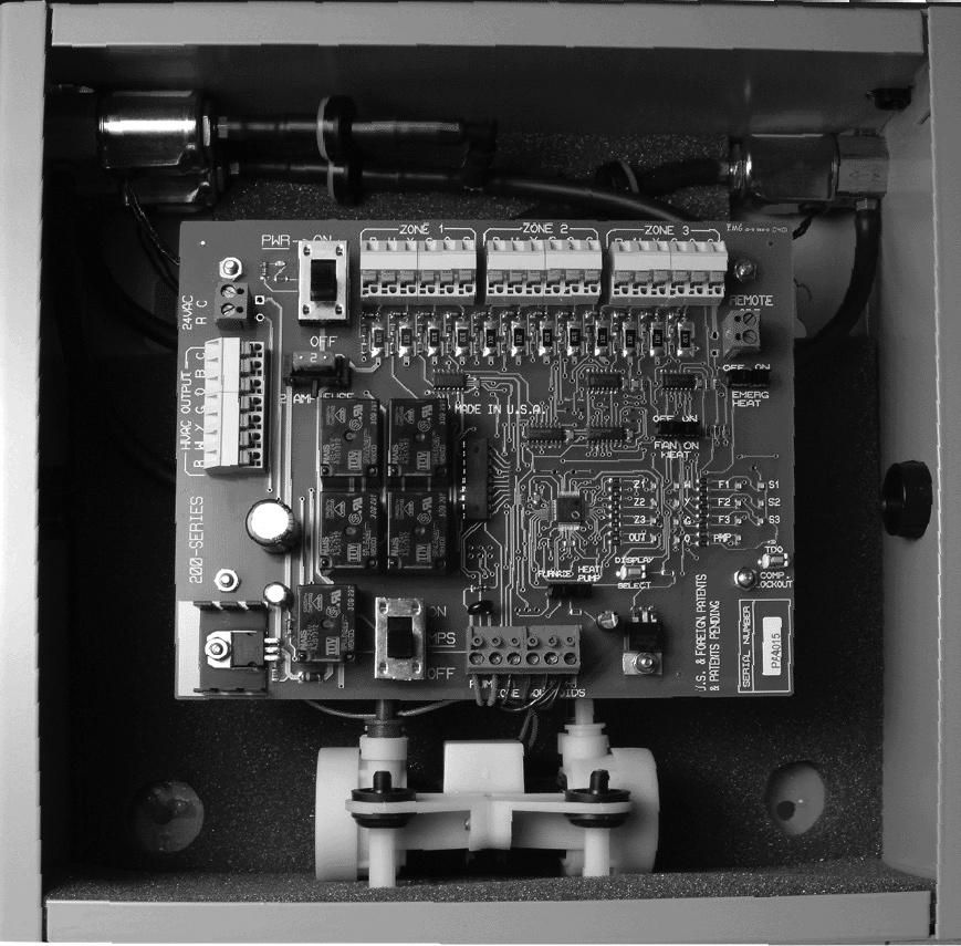
6 Circuit Board Layout & Equipment Notes LED Display Inset # Name Description 1 PWR On/Off w/led The ZonePak System is powered by a 40 VA 24VAC transformer (provided). This switch and the HVAC system equipment power switch must always be in the OFF position when connecting wires to any terminals. (See Caution Statement page 2) 2 24VAC Terminals The ZonePak 40 VA transformer (provided) must be connected to these two terminals. Output to the HVAC equipment is controlled by a set of dry-contact relays. The HVAC R signal is switched and sent out to start the appropriate equipment when called by any zone thermostat however completely isolated from the thermostat power supply. (Connect hot or + side of HVAC equipment transformer (24 VAC) to this terminal.) R Connect to W1 of furnace. (Aux. heat terminal if heat pump is installed.) 3 HVAC Output Terminals W Y Connect to compressor contactor. Connect to equipment fan relay. G Connect either O or B to heat pump reversing valve, as required by heat pump manufacturer. O/B Use the O signal if the unit reverses in the cooling cycle; the B if it reverses in the heating cycle. C Connect common side of HVAC equipment transformer (24 VAC) to this terminal. 4 Terminals Connect thermostat wires (R,W,Y,G,O, and C) as required for your application. Note which thermostats are connected to which zones. (24VAC) 6
7 5 ODT Terminals Emergency Heat changeover terminals REMOTE ODT (5VDC) are used for remote switching by outdoor thermostat. This remote switch (or thermostat) will change heat pump operation to backup heat or fossil fuel. If a heat pump is installed with a fossil fuel furnace (without fossil fuel kit) do not connect the (W) wires from the zone thermostats. 6 Emergency Heat Switch Emergency Heat changeover switch, is used to manually bypass the heat pump and energize the auxiliary heat on a call for service (heat pump application only). 7 Fan-on-Heat Switch This switch in the ON position will provide automatic fan operation on a call for heating for electric furnaces, hot water coils, steam coils, etc. 8 S1,S2,S3 Solenoid LEDs These LEDs indicate which zones are being served and their zone dampers are open. [S1,S2,S3(Red)] 9 Fault Code LEDs F1,F2,F3 The 3 Fault Code LEDs illuminate when a themostat sends an illegal call. A call is illegal if it is improper for the type of HVAC equipment installed. LED will stay lit until the power switch is cycled. F1 = illegal call on zone 1. F2 = illegal call on zone 2. F3 = illegal call on zone 3. Illegal calls are ignored. The system will continue to operate normally, serving any legal calls. Illegal calls may indicate a thermostat or wiring fault in the affected zone. 10 PMP LED Pump LED (Red) light is ON anytime the pump is running. 11 Comp Lockout LED Compressor lockout LED. Any time the zoning system turns the compressor off it holds it off for four(4) minutes. This prevents short cycling the compressor. 12 TDO Time Delay Override This momentary contact, Time Delay Override switch (TDO), is provided on the PC board to speed the checkout of the zoning system. Before using this TDO switch, you must disconnect the HVAC R wire in order to avoid short cycling the equipment. The COMP LOCKOUT LED (Red) light will indicate 4 minute compressor lockout condition. 13 System Status LEDs The DISPLAY SELECT switch controls what information is displayed on the Service LEDs. By default the LEDs indicate the HVAC Output Signal. It will illuminate the Out LED and the appropriate service LEDs to indicate the call to the equipment. 14 Display Select Switch Push the button once and the system illuminates the Zone 1 (Z1) LED and shows what the Zone 1 is calling for. Push it again and The Zone 2 (Z2) LED illuminates and the display LEDs show what Zone 2 is calling for. Push the button a third time and Zone 3 is displayed. Pushing it a fourth time will return it to the output display. The system will revert to displaying the Output signal anytime the button is idle for 1 minute. 15 Furnance/ HeatPump Switch 16 Solenoid Terminals and Pump Terminals This switch sets the operational mode for the zoning system. Set the switch for the type of equipment that the zoning system is controlling. Factory connection for the Zone Solenoids (24VDC). Solenoids are energized to provide pressure to close the dampers and de-energized to provide vacuum to open the dampers. Factory connections for the pressure/vacuum pump.(24vac) The pump operates only when a thermostat calls for a heat/cool or fan operation or when the MPS switch is in the ON position. 17 MPS Switch MPS switch starts pump and opens all zone dampers when Power Switch is OFF. 7
8 Commissioning Procedure FAN CHECK-OUT. Set all thermostats to the OFF position and all fan switches to AUTO.. Turn the HVAC system and the ZonePak system PWR switches to ON. The LED light next to the switch will illuminate on the ZonePak control panel. 3. Turn the Zone 1 thermostat fan switch ON. The S1 indicator, the Fan output (G) and Pump LED lights will illuminate. The fan in the HVAC system will turn on. The pump and solenoids will position all the dampers. Check the air flow at all register outlets to determine that only Zone 1 dampers are open and all other dampers are closed. 4. Follow the above procedure for all other zones. HEATING & COOLING CHECK-OUT. Set all thermostats to the OFF position and all fan switches to AUTO before starting heating system check out.. Set Zone 1 thermostat to the HEAT position and turn thermostat up so that the thermostat is calling for heat. The S1 indicator, the W output, and the pump LED lights will illuminate. The pump and solenoids will position all the dampers. Check to see that the heating circuit is energized. If heat pump is installed, check operation of Emergency Back-up heating. Turn the thermostat down until the thermostat is satisfied. The LED lights will go out and the pump will stop. Dampers will remain open in the last zone that called. For heat pump, LED indication will be Y & G. 3. Set thermostat for Zone 1 to the COOL position. Turn thermostat down so that the thermostat is calling for cooling. The S1 indicator, the Y and G outputs and the pump LED will illuminate. The pump and solenoids will position all the dampers. Check to see that the compressor contactor is energized. For heat pump, LED indication will be Y, G & O. 4. Place Zone 1 thermostat in the OFF position. 5. Follow the above procedure for all other zones. IF ALL ELSE FAILS Turn the ZonePak power switch to OFF. 2. Disconnect the thermostat wires from any zone and connect them to the HVAC OUTPUT terminals. 3. Turn the ZonePak switch ON, this will open ALL zone dampers. The HVAC system will work without the benefit of the zoning system. The heating and air conditioning equipment is now controlled by that thermostat. All dampers will stay open. If the HVAC system does not work in this configuration, you probably have a wiring, thermostat or other equipment problem. Troubleshooting Matrix Problem Possible Causes Correction No LEDs lit Dampers not opening or closing 1- Power Switch OFF 2- No 24VAC from transformer 1- Insufficient Pressure/Vacuum 2- Binding on rectangular duct Turn Power Switch to ON. Check Transformer input/output. Replace if 110V is present w/ no 24vac output. Check for open tube ends or leaky damper actuator. Cut opening to specified dimension per installation instructions. HVAC system not operating One zone not being served Slave zone not operating 1- No equipment control power 2- Output relay failure 1- Illegal call at panel 2- Faulty board component No Common wire from equipment control transformer Check equipment transformer and/or control wiring Check continuity between R and calling circuit (W,Y,G) at the HVAC Output, if none and the appropriate output LED is lit, replace board. Check wiring of thermostat to Panel ( O is energized with cooling call only). If call is legal and no service provided, replace PC board Connect C from equipment to C of HVAC Output terminals in panel. Low air flow to zones 1- Bypass Damper Open 2- Restriction in system Adjust weight on bypass damper for maximum static to smallest zone. Check filter, DX-coil, or secondary heat exchanger coil for blockage. For additional technical support, please call:
Installation & Operation Instructions
 Installation & Operation Instructions 200 MPS Series Arzel Zoning Technology, Inc. 4801 Commerce Pkwy. Cleveland, OH 44128 Ph: (216) 831-6068 or Toll-Free (800) 611-8312 Fax: (216) 831-6074 www.arzelzoning.com
Safety & Installation Instructions
 Model 6303 & 6302 Zoned Comfort Control Safety & Installation Instructions READ AND SAVE THESE INSTRUCTIONS 61001212A 6302-6303 Zoned Comfort Control Install.indd 1 TABLE OF CONTENTS SAFETY INSTRUCTIONS..........................................
CommStat 6. Controller for Redundant HVAC Systems PRODUCT DATA SHEET
 CommStat 6 Controller for Redundant HVAC Systems PRODUCT DATA SHEET General Description The CommStat 6 HVAC controller is designed for controlling up to six redundant air conditioners in an E-House or
Safety & Installation Instructions
 Model 6203 & 6202 Zoned Comfort Control Safety & Installation Instructions READ AND SAVE THESE INSTRUCTIONS 61001213A 6202-6203 Zoned Comfort Control Install.indd 1 TABLE OF CONTENTS SAFETY INSTRUCTIONS..........................................
CommStat 4. Controller for Redundant Telecom HVAC Systems PRODUCT DATA SHEET. Features and Benefits
 CommStat 4 PRODUCT DATA SHEET Controller for Redundant Telecom HVAC Systems General Description The CommStat 4 is an HVAC controller designed specifically for controlling two redundant air conditioners,
Safety & Installation Instructions
 Premium Programmable Thermostat Safety & Installation Instructions Model 8570 READ AND SAVE THESE INSTRUCTIONS TABLE OF CONTENTS PAGE SPECIFICATIONS............................. 1 WIRE REQUIREMENTS.........................
CommStat 4 Controller
 CommStat 4 Controller CommStat 4 Telecom HVAC Controller The CommStat 4 is an HVAC controller designed specifically for controlling two redundant air conditioners, heat pumps and air conditioners with
QUICK REFERENCE GUIDE P.C. BOARD/WALL THERMOSTAT FOR 6536A891, 6536B891 & 6536C891 TWO TON PACKAGED HEAT PUMPS
 QUICK REFERENCE GUIDE P.C. BOARD/WALL THERMOSTAT FOR 6536A891, 6536B891 & 6536C891 TWO TON PACKAGED HEAT PUMPS Note: This manual may also be used for 6536-871 series heat pumps if the 6535-3209 Replacement
Emerson Inspire 1HDEZ Installation Instructions. Thermostat/Interface Equipment Control TROUBLESHOOTING
 Emerson Inspire 1HDEZ-1521 Installation Instructions Thermostat/Interface Equipment Control TROUBLESHOOTING FAILURE TO READ AND FOLLOW ALL INSTRUCTIONS CAREFULLY BEFORE INSTALLING OR OPERATING THIS CONTROL
TZ-4 TotalZone Zone Control Panel
 TZ-4 TotalZone Zone Control Panel FEATURES PRODUCT DATA APPLICATION The TZ-4 TotalZone Zone Control Panel controls single-stage, multi-stage, conventional or heat pump heat/cool equipment. It controls,
DIGI3U. Zoning Systems. Installation Guide. That s all we do. Three-Zone, Universal Controller for Gas/Electric or Heat Pump Applications
 Installation Guide DIGIU Three-Zone, Universal Controller for Gas/Electric or Heat Pump Applications -Zone Controller for the RNC Market Part #DMAN October 004 Zoning Systems That s all we do. INTRODUCTION
QUICK REFERENCE GUIDE P.C. BOARD/WALL THERMOSTAT FOR 6535D, 6537C, 6538 A&B SERIES TWO TON PACKAGED HIGH EFFICIENCY HEAT PUMPS
 QUICK REFERENCE GUIDE P.C. BOARD/WALL THERMOSTAT FOR 6535D, 6537C, 6538 A&B SERIES TWO TON PACKAGED HIGH EFFICIENCY HEAT PUMPS RV Products A Division of Airxcel, Inc. P.O. Box 4020 Wichita, KS 67204 1-316-832-4357
T-32-TS Touchscreen Thermostat. Installation Manual
 T-32-TS Touchscreen Thermostat Installation Manual TABLE OF CONTENTS Introduction...4 Getting Started...5 Installing the Thermostat...6, 8 Disassembly...6 Thermostat Location...6 Mounting the Subbase...6,
LZP-2 ZONE CONTROL PANEL
 2004 Lennox Industries Inc. Dallas, Texas, USA ZONING SYSTEM 504,926M 5/2004 Litho U.S.A. LZP-2 ZONE CONTROL PANEL INSTALLATION INSTRUCTIONS FOR ZONE CONTROL PANELS USED WITH LENNOX HEATING AND COOLING
50M Integrated Single or Two-Stage HSI Integrated Furnace Control Kit INSTALLATION INSTRUCTIONS
 50M56-743 Integrated Single or Two-Stage HSI Integrated Furnace Control Kit INSTALLATION INSTRUCTIONS FAILURE TO READ AND FOLLOW ALL INSTRUCTIONS CAREFULLY BEFORE INSTALLING OR OPERATING THIS CONTROL COULD
Safety & Installation Instructions
 Model 8800 Universal Communicating Thermostat Safety & Installation Instructions READ AND SAVE THESE INSTRUCTIONS Table of contents Installation Installation location recommendations... 2 Thermostat mounting...
Emerson Blue Easy Set 1H/1C
 Emerson Blue Easy Set 1H/1C Model: 1F86EZ-0251 Non-Programmable Thermostat with 3 Temperature Pre-Sets Home, Sleep and Away Installation Instructions and User Guide Message to Homeowner Congratulations
WHITE-RODGERS COMFORT-SET 90 SERIES
 INSTALLATI DESCRIPTI WHITE-RODGERS COMFORT-SET 90 SERIES MULTI-STAGE/HEAT PUMP INSTALLATI/CFIGURATI This White-Rodgers Automatic Setback Digital Thermostat uses microcomputer technology to provide precise
1F Non-programmable Electronic Digital Heat Pump Thermostat INSTALLATION AND OPERATION INSTRUCTIONS
 FAILURE TO READ AND FOLLOW ALL INSTRUCTIONS CAREFULLY BEFORE INSTALLING OR OPERATING THIS CONTROL COULD CAUSE PERSONAL INJURY AND/OR PROPERTY DAMAGE. DESCRIPTION Your new White-Rodgers Digital Thermostat
Safety & Installation Instructions
 Model 8476 Thermostat with Event-Based Air Cleaning Safety & Installation Instructions READ AND SAVE THESE INSTRUCTIONS Table of contents Installation Installation location recommendations... 3 Outdoor
Operator: Save these instructions for future use!
 WHITE-RODGERS 1F83-51 Non-Programmable Electronic Digital Multi-Stage Thermostat INSTALLATION AND OPERATION INSTRUCTIONS Operator: Save these instructions for future use! FAILURE TO READ AND FOLLOW ALL
Installer Guide. WARNING Important Safety Information. 1 Specifications
 1 Specifications cont. Premier Series Universal Auto Changeover Up to 3 Heat / 2 Cool Heat Pump or 2 Heat / 2 Cool Conventional Thermostat Installer Guide Before Installing, Programming or Operating, PLEASE
DXM CONTROLS. DXM Digital Heat Pump Controllers. Application, Operation, & Maintenance. Table of Contents
 Table of Contents DXM CONTROLS DXM Electronic Controls Features Comparison 2 DXM Electronic Heat Pump Controls 3 DXM Physical Dimensions & Layout 4 DXM Controls 5 DXM Service & Application Notes 13 Troubleshooting
50M56U-843 INSTALLER MUST READ DESCRIPTION PRECAUTIONS WARNING CAUTION
 50M56U-843 Universal Single Stage HSI Integrated Furnace Control Kit INSTALLATION INSTRUCTIONS INSTALLER MUST READ PAGE 3 CONTAINS WIRING HARNESS AND BLOWER CONNECTION INSTRUCTIONS FOR ALL APPLICATIONS
Installer Guide. WARNING Important Safety Information. 1 Specifications
 1 Specifications cont. Premier Series Universal Auto Changeover Up to 3 Heat / 2 Cool Conventional and Heat Pump Thermostat Installer Guide Before Installing, Programming or Operating, PLEASE READ ALL
OPERATION INSTRUCTIONS DEMAND DEFROST CONTROL BOARD MODEL FOR USE WITH MODELS: AFFINITY, ECHELON, ACCLIMATE HEAT PUMP SERIES
 OPERATION INSTRUCTIONS DEMAND DEFROST CONTROL BOARD MODEL 500644 FOR USE WITH MODELS: AFFINITY, ECHELON, ACCLIMATE HEAT PUMP SERIES A047-001 FIGURE 1: Demand Defrost Control Module ANTI-SHORT CYCLE DELAY
Safety & Installation Instructions
 8400 Series Thermostats Safety & Installation Instructions READ AND SAVE THESE INSTRUCTIONS 61000652C 8400 Tstat Install.indd 1 10/13/09 11:08:56 AM Table of contents Installation Installation location
Commercial Touchscreen Thermostat
 55,13M 1/27 Supersedes 12/25 Commercial Touchscreen Thermostat 25 Lennox Industries, Inc. Dallas, Texas, USA APPLICATION Page 1 INSTALLATION INSTRUCTIONS The Lennox Commercial Touchscreen Thermostat provides
Operator: Save these instructions for future use!
 WHITE-RODGERS 50A55-286 Integrated Furnace Control INSTALLATION INSTRUCTIONS Operator: Save these instructions for future use FAILURE TO READ AND FOLLOW ALL INSTRUCTIONS CAREFULLY BEFORE INSTALLING OR
Safety & Installation Instructions
 8400 Series Thermostats Safety & Installation Instructions READ AND SAVE THESE INSTRUCTIONS 61000652A 8400 Tstat Install.indd 1 7/23/09 2:20:45 PM Table of contents Installation Installation location recommendations...
UNIT DIGITAL CONTROLS APPLICATION, OPERATION & MAINTENANCE
 DM2 Digital Heat Pump Controller Rev: 3 November 2017 DM2 Overview 3 Physical Dimensions and Layout 4 Layout and Connections 5 Field Selectable Inputs 6 Safety Features 8 Unit Operation Description 10
Installation, Operation, and Troubleshooting Instructions
 Installation, Operation, and Troubleshooting Instructions 48/50HJ004-024 48/50TJ004-028 Apollo Control GENERAL The Apollo control is a relay pack which is factory wired and mounted in the Carrier rooftop
T8411R Electronic Heat Pump Thermostat
 T84R Electronic Heat Pump Thermostat INSTALLATION INSTRUCTIONS The T84R Heat Pump Thermostat provides 24V control of two-stage heating and one-stage cooling heat pump system with manual changeover from
Operator: Save these instructions for future use!
 031-01284-000/50A55-241 Integrated Furnace Control INSTALLATION INSTRUCTIONS Operator: Save these instructions for future use! FAILURE TO READ AND FOLLOW ALL INSTRUCTIONS CAREFULLY BEFORE INSTALLING OR
1F98EZ-1421, Easy Install
 1F98EZ-1421, -1441 Easy Install For up to 4 Stages and 2 Stages Cool INSTALLATION INSTRUCTIONS APPLICATIONS Configuration Options Single Stage Multi Stage Pump Pump with Dual Fuel FAILURE TO READ AND FOLLOW
Zoning System for Residential Communicating, Variable Air Volume Heating/Cooling Systems
 PRODUCT SPECIFICATIONS ZONING IHARMONY Zoning System for Residential Communicating, Variable Air Volume Heating/Cooling Systems Bulletin No. 20663 November 207 Supersedes August 205 COMPONENTS AND EQUIPMENT
INSTALLATION & OPERATION MANUAL
 INSTALLATION & OPERATION MANUAL Model TME- * * Balance of model number is determined by customer specifi ed limits and Setbacks. AUTOMATIC SETBACK THERMOSTAT LIGHT SENSING OR CONTACT CLOSURE FOR LOW VOLTAGE
Heat Pump Defrost Board Replacement Kit
 Bard Manufacturing Company, Inc. Bryan, Ohio 43506 8620-223 Heat Pump Defrost Board Replacement Kit KIT FEATURES This kit is made up of the current defrost control board 8201-129 and a new defrost sensor.
Installation Instructions / User s Manual TSTAT0406 and TSTAT0408
 997-060180-5 Installation Instructions / User s Manual TSTAT0406 and TSTAT0408 4 HEAT 2 COOL DUAL FUEL TSTAT0406 & TSTAT0408-4 WIRE CAPABLE THERMOSTAT (NAXA00201DB Daughter Board sold separately) LEFT
ZonexCommander. ZonexCommander(Plus) Installation and Applications Manual. Network All Your HVAC Equipment
 Installation and Applications Manual. Network All Your HVAC Equipment") ZonexCommander ZonexCommander(Plus) Network All Your HVAC Equipment Centralized DDC Communications for Stand-Alone HVAC and Zoned Systems Installation and Applications Manual Part #ZCMAN Rev. Oct 2014
ZonexCommander ZonexCommander(Plus) Network All Your HVAC Equipment Centralized DDC Communications for Stand-Alone HVAC and Zoned Systems Installation and Applications Manual Part #ZCMAN Rev. Oct 2014
2 THERMOSTAT DETAILS 3 REMOVING OLD THERMOSTAT
 CONTENTS Installation Instructions for Heating & Air Conditioning 1F79 n-programmable Heat Pump Thermostat Preparations... 1 Thermostat Details... 1 Removing Old Thermostat... 1-2 Mounting and Wiring...
Installation and Setup Guide
 Installation and Setup Guide Color Touchscreen Programmable Commercial Thermostat ComfortSense 7500 Model: C0STAT06FF1L Cat: 13H15 507506-01 3/2016 Supersedes 10/2015 Table of Contents Shipping and Packing
Operator: Save these instructions for future use!
 50A65-843 Universal Integrated Furnace Control INSTALLATION INSTRUCTIONS Operator: Save these instructions for future use! FAILURE TO READ AND FOLLOW ALL INSTRUCTIONS CAREFULLY BEFORE INSTALLING OR OPERATING
TCONT602AF22MA. Programmable Comfort Control. Installation Instructions 18-HD37D1-1
 TCONT602AF22MA Programmable Comfort Control Installation Instructions 18-HD37D1-1 Product Application This Comfort Control provides electronic control of 24 VAC single-stage and multistage heating and
RC-112 Two Speed Heat Pump 3 Stage Heat / 2 Stage Cool With Energy Efficient Control
 O M N I S T A T ELECTRONIC COMMUNICATING THERMOSTAT Installation Manual RC-112 Two Speed Heat Pump 3 Stage Heat / 2 Stage Cool With Energy Efficient Control Document Number 13I00-5 November, 1997 CONTENTS
Installation, Start-Up, and Operating Instructions
 Installation, Start-Up, and Operating Instructions CONTENTS Page SAFETY CONSIDERATIONS...1 GENERAL...1 INSTALLATION...1-5 Install Batteries...1 Select Transmitter Location (Optional)...1 Mount Transmitter
DXM2 Digital Heat Pump Controller
 APPLICATION, OPERATION & MAINTENANCE MANUAL DM2 Digital Heat Pump Controller Heat Controller, Inc. 1900 Wellworth Ave. Jackson, MI 49203 (517)787-2100 www.heatcontroller.com Application, Operation, & Maintenance
T8401C Electronic Thermostats
 T8401C Electronic Thermostats INSTALLATION INSTRUCTIONS APPLICATION The T8401C Thermostat provides single-stage, nonprogrammable temperature control for 24 Vac heating cooling systems with manual changeover
IF79 CAUTION CONTENTS YOUR THERMOSTAT REPLACES 1 PREPARATIONS. Installation Instructions for. Heating & Air Conditioning
 CONTENTS Installation Instructions for Heating & Air Conditioning IF79 n- Programmable Heat Pump Thermostat Preparations... 1 Thermostat Details... 1 Removing Old Thermostat... 1-2 Mounting and Wiring...
EnviroZone-4 & EnviroZone-2 Quick-Start Guide
 EnviroZone-4 & EnviroZone-2 Quick-Start Guide This guide is intended to give the installer a brief set of instructions about how to set up the FHP EnviroZone System. For more detailed information about
Detailed Installer Guide
 Detailed Installer Guide Programmable Thermostats PREMIER SERIES 5020 Single Stage Heat / Cool Conventional or Heat Pump 5220 Up to 3 Heat / 2 Cool Heat Pump Up to 2 Heat / 2 Cool Conventional 1 Specifications
Operator: Save these instructions for future use!
 50A66-743 Integrated Furnace Control Operator: Save these instructions for future use! FAILURE TO READ AND FOLLOW ALL INSTRUCTIONS CAREFULLY BEFORE INSTALLING OR OPERATING THIS CONTROL COULD CAUSE PERSONAL
T8611M Deluxe Programmable Heat Pump Thermostats
 T8611M Deluxe mable Heat Pump Thermostats INSTALLATION INSTRUCTIONS APPLICATION The T8611M Deluxe mable Heat Pump Thermostat provides electronic control of 24 Vac single-zone two compressor or two speed
50M56U-843 Universal Single Stage HSI Integrated Furnace Control Kit INSTALLATION INSTRUCTIONS
 50M56U-843 Universal Single Stage HSI Integrated Furnace Control Kit INSTALLATION INSTRUCTIONS INSTALLER MUST READ PAGE 3 CONTAINS WIRING HARNESS AND BLOWER CONNECTION INSTRUCTIONS FOR ALL APPLICATIONS
VisionPRO 8000 with Wi-Fi
 VisionPRO 8000 with Wi-Fi FEATURES PRODUCT DATA Thermostat acquires weather data through either a wired sensor or an Internet connection, making for a truly universal installation. U1 Terminals One set
EL-TSTAT-8820 Safety & Installation Instructions
 EL-TSTAT-8820 Safety & Installation Instructions TABLE OF CONTENTS WI-FI SETUP Wi-Fi Setup 2 INSTALLATION Installation location recommendations 3 Outdoor temperature sensor (included) 3 Remote temperature
FP EZ4F 4 Zone Controller
 4 Zone Controller READ THIS GUIDE BEFORE INSTALLING CONTROLLER Zone Controller Installa on and Start up Guide Rev 20170801 Ver 16 Input Ra ngs: Voltage: 18 40 VAC 50/60 HZ transformer of 40 VA or more
Programmable Touchscreen Thermostats. Disconnect power before beginning installation.
 Installer Guide Touchscreen Programmable Touchscreen Thermostats 6100 Single Stage Heat / Cool Conventional or Heat Pump 6300 Up to 4 Heat / 2 Cool Heat Pump Up to 3 Heat / 2 Cool Conventional 6400 Up
Tri-Stack Smart System
 Tri-Stack Smart System TM Notes & Warnings - The protection provided by this equipment may be impaired if it is not used in the manner specified herein. - Ensure all wiring meets applicable national and
PS4000 and PS5000 Touchscreen Programmable Thermostat Installation and Owners Manual Robertshaw 01/
 PS4000 and PS5000 Touchscreen Programmable Thermostat Installation and Owners Manual www.robertshaw.com 2016 Robertshaw 01/16 352-00244-001 IMPORTANT SAFETY INFORMATION WARNING: ELECTRICAL SHOCK HAZARD
Operator: Save these instructions for future use!
 WHITE-RODGERS 50A55-474 & 50A55-571 Integrated Furnace Controls INSTALLATION INSTRUCTIONS Operator: Save these instructions for future use! FAILURE TO READ AND FOLLOW ALL INSTRUCTIONS CAREFULLY BEFORE
50A Integrated Furnace Control
 Goodman White-Rodgers 0130F00005 PCBBF110 PCBBF123 50A55-743 0130F00005S PCBBF110S PCBBF123S 50A55-289 B1809926 PCBBF112 50T55-289 B1809926S PCBBF112S 50A55-743 Integrated Furnace Control INSTALLATION
Operator: Save these instructions for future use!
 WHITE-RODGERS 1F82-51 Programmable Electronic Digital Heat Pump Thermostat INSTALLATION AND OPERATION INSTRUCTIONS Operator: Save these instructions for future use! FAILURE TO READ AND FOLLOW ALL INSTRUCTIONS
RC-2000 Thermostat Installation Instructions
 RC-2000 Thermostat Installation Instructions DESCRIPTION The RC-2000 is a precision digital thermostat designed for 24 VAC heating and cooling systems. The RC-2000 will support the following systems: Single
Installation Instructions
 T2 -PAC01 -A, T2 -NAC01 -A T2 -PHP01 -A, T2 -NHP01 -A LEGACYt SERIES THERMOSTATS Installation Instructions A07047 Legacy Series Programmable Thermostat A07046 Legacy Series Non-Programmable Thermostat
PRO Installation. Thermostat Wi-Fi
 PRO Installation Thermostat Wi-Fi 1 Designed by the pros for the pros There are a lot of choices when it comes to buying a thermostat, but only one combines 125 years of experience and the latest connected
PECO. WavePRO Wireless System INSTALLATION GUIDE: T2500 THERMOSTAT AND R2500 RECEIVER. The Peco WavePRO Wireless System
 PECO WavePRO Wireless System INSTALLATION GUIDE: T2500 THERMOSTAT AND R2500 RECEIVER Wireless control for up to 3-HEAT/ 2-COOL heat pump and conventional systems (gas,oil,electric). Benefits: Reduced installation
Model number is located on back of thermostat.
 Installer Manual Programmable Thermostats PREMIER SERIES 5020 Single Stage Conventional Systems or Single Stage Heat Pumps with Auxiliary Heat 5220 Up to 3 Heat / 2 Cool Heat Pump Up to 2 Heat / 2 Cool
Comfort System T-21-P Touchscreen Thermostat Installation Manual
 Comfort System T-21-P Touchscreen Thermostat Installation Manual Version 1.40 INTRODUCTION The Comfort System T-21-P is a feature-rich touchscreen thermostat that can be battery powered or hardwired to
Phone-A-Stat. MODEL Command Center With Thermostat Operation, Maintenance & Installation Manual. Introduction.
 Introduction The UL listed Phone-A-Stat (model # 7632 ) is designed and approved for the safe operation of remotely controlling four independent loads, such as a sprinkler system or a water heater via
50A Integrated Furnace Control
 50A56-956 Integrated Furnace Control INSTALLATION INSTRUCTIONS FAILURE TO READ AND FOLLOW ALL INSTRUCTIONS CAREFULLY BEFORE INSTALLING OR OPERATING THIS CONTROL COULD CAUSE PERSONAL INJURY AND/OR PROPERTY
PRO Installation. Touch Wi-Fi Thermostat
 PRO Installation Touch Wi-Fi Thermostat 1 Designed by the pros for the pros There are a lot of choices when it comes to buying a thermostat, but only one combines 125 years of experience and the latest
CONTROLS THERMOSTATS Bulletin No November 2001 Supersedes September 2001 INNOVATOR PROGRAMMABLE THERMOSTATS ENGINEERING DATA
 ENGINEERING DATA CONTROLS THERMOSTATS Bulletin No. 210125 November 2001 Supersedes September 2001 INNOVATOR PROGRAMMABLE THERMOSTATS L21 SERIES THERMOSTATS HEAT/COOL SYSTEMS Features (All Models): Extra
H32 Uni- Zone Model H32
 H32 Uni- Zone Model H32 Installation and Operating Instructions Controlling Your Comfort Room By Room F o l l o w u s o n H32 PANEL FEATURES System Mode Indicator LED Power Indicator LED HVAC Equipment
Smart Temp. ApolloP/n Installation Manual. Version 1.0
 Smart Temp ApolloP/n 44-800 Installation Manual Version 1.0 TABLE OF CONTENTS Introduction...6 Getting started...7 Installing the thermostat...8 Disassembly...8 Thermostat location...8 Mounting the subbase...8,
ZonexCommander. ZonexCommander(Plus) Installation and Applications Manual. Network All Your HVAC Equipment
 Installation and Applications Manual. Network All Your HVAC Equipment") ZonexCommander ZonexCommander(Plus) Network All Your HVAC Equipment Centralized DDC Communications for Stand-Alone HVAC and Zoned Systems Installation and Applications Manual Part #ZCMAN Rev. July 2010
ZonexCommander ZonexCommander(Plus) Network All Your HVAC Equipment Centralized DDC Communications for Stand-Alone HVAC and Zoned Systems Installation and Applications Manual Part #ZCMAN Rev. July 2010
SC Installation, Operation & Application Guide
 SC 5811 2 Heat/2 Cool Auto Changeover Hardwire Programmable Electronic Thermostat 7-Day, 5-2-Day or 5-1-1-Day Programmable Configurable 2-Stage Heat/2-Stage Cool Systems 2-Stage Heat Pump Systems Large
T7200D,E Series 2000 Commercial Microelectronic Thermostats
 T7200D,E Series 2000 Commercial Microelectronic Thermostats INSTALLATION INSTRUCTIONS APPLICATION The T7200D,E Thermostats provide electronic control of 24 Vac commercial single-zone heating, ventilating
SERVICE MANUAL FOR 6537 & 6538 SERIES TWO TON HIGH EFFICIENCY PACKAGED HEAT PUMPS
 SERVICE MANUAL FOR 6537 & 6538 SERIES TWO TON HIGH EFFICIENCY PACKAGED HEAT PUMPS TABLE OF CONTENTS 1. Warnings.................................................................. 2 2. Accessibility Of Appliance....................................................
Must be installed by a trained, experienced technician
 Installation Guide VisionPRO TH8000 Series Touch-screen Programmable Thermostat This manual covers the following models TH8321097: For up to 3 Heat/2 Cool heat pump or up to 2 Heat/2 Cool conventional
1F95EZ-0671 Non-Programmable 7 Day. Maximum Stages Heat/Cool 1/1 2/2 3/1 4/2
 Save these instructions for future use! FAILURE TO READ AND FOLLOW ALL INSTRUCTIONS CAREFULLY BEFORE INSTALLING OR OPERATING THIS CONTROL COULD CAUSE PERSONAL INJURY AND/OR PROPERTY DAMAGE. APPLICATIONS
Digital Programmable
 www.geappliances.com Digital Programmable Thermostats Operating Instructions Auto Changeover..........10 Day/Time Setting Mode.....6 Default Mode...............4 Fan Control...............10 Hold and Temporary
T8602C Chronotherm IV Deluxe Programmable Thermostats
 T8602C Chronotherm IV Deluxe mable Thermostats INSTALLATION INSTRUCTIONS APPLICATION The T8602 Chronotherm IV Deluxe mable Thermostat provides electronic control of 24 Vac single-stage heating and cooling
Safety, Installation, and Operation Manual
 Automatic Steam Humidifier Control Safety, Installation, and Operation Manual READ COMPLETE INSTALLATION INSTRUCTIONS BEFORE STARTING. WARNING This product must be installed by a qualified heating and
Lyric T6 Pro Wi-Fi. Professional Install Guide. Compatibility. Customer assistance. Programmable Thermostat
 Lyric T6 Pro Wi-Fi Programmable Thermostat Professional Install Guide Package Includes: Lyric T6 PRO Wi-Fi Thermostat UWP Mounting System Honeywell Standard Installation Adapter (J-box adapter) Honeywell
INSTALLATION MANUAL. * If using remote sensors the thermostat must be hardwired. Need Help?
 INSTALLATION MANUAL This manual covers the following models: T955W Master Thermostat Base Module Thermostat Applications Guide Description Gas or Oil Heat Electric Furnace Heat Pump (No Aux. or Emergency
Verasys System Operation Overview Technical Bulletin
 Contents subject to change. Verasys System Operation Overview Technical Bulletin Code No. LIT-12012370 Issued January 2016 Refer to the QuickLIT Web site for the most up-to-date version of this document.
INSTALLATION INSTRUCTIONS and OPERATING MANUAL. *Aquastat is a registered trademark of Honeywell International, Inc.
 MODEL 3200-Plus Temp Limit / LWCO Control with Thermal Targeting for Water Boilers 120 VAC Input / 24 VAC Burner Circuit PATENT. 8,931,708; 8,844,834; 7,891,572; others pending INSTALLATION INSTRUCTIONS
Operator: Save these instructions for future use!
 WHITE-RODGERS 1F81-51 Programmable Electronic Digital Multi-stage Thermostat INSTALLATION AND OPERATION INSTRUCTIONS Operator: Save these instructions for future use! FAILURE TO READ AND FOLLOW ALL INSTRUCTIONS
Product Data. Features/Benefits. 33CS Carrier Comfort System Variable Volume and Temperature (VVT )
") Product Data 33CS Carrier Comfort System Variable Volume and Temperature (VVT ) The VVT Comfort System provides the following features and benefits: 365-day scheduling, daylight savings compensation, and
Product Data 33CS Carrier Comfort System Variable Volume and Temperature (VVT ) The VVT Comfort System provides the following features and benefits: 365-day scheduling, daylight savings compensation, and
Installation Instructions
 TP --- PRH --- A, TP --- NRH --- A PerformancetSeries Edger Thermidistatt Control Installation Instructions Programmable Control A07049 A07048 Non---Programmable Control NOTE: Read the entire instruction
Premier 2-Zone Controller model Installer Guide
 Premier 2-Zone ontroller model 140202 Installer uide ONTENTS 1 Specifications 4 onfiguration 2 Suitable Mounting Locations 5 System heckout 3 Wiring Diagrams 6 Operation Warning Read all of the instructions
Installation Instructions
 P700U -21NHP Base Non -Programmable Thermostats Installation Instructions Designed and Assembled in the USA. US patents: US20060165149 A1, USD578026 SI, US6205041 B1 A14005 Base Non---Programmable Thermostat
Aprilaire Dehumidifier Troubleshooting Manual Models 1830 & 1850
 Aprilaire Dehumidifier Troubleshooting Manual Models 1830 & 1850 Table of Contents Troubleshooting Diagnostic Codes... 2 E1, E2... 2 E3, E4... 3 E5, E6 & E7... 7 E8... 8 E9 9 Verifying Capacity... 10 Water
QUICK INSTALLATION GUIDE
 QUICK INSTALLATION GUIDE Read Installer Notes before removing cover from Thermostat. 1F85RF-275 Wireless Remote Kit INSTALLER NOTES IMPORTANT Do not remove battery tags to activate the thermostat or wireless
ACONT600AF11MA Programmable Comfort Control
 ACONT600AF11MA Programmable Comfort Control Installation Instructions Pub. No. 11-HD02D10-4 69-1832-03 Product Application This Comfort Control provides electronic control of 24 VAC single-stage heating
1F Non-Programmable Electronic Digital Multi-Stage Thermostat INSTALLATION AND OPERATION INSTRUCTIONS
 1F83-261 Non-Programmable Electronic Digital Multi-Stage Thermostat INSTALLATION AND OPERATION INSTRUCTIONS Operator: Save these instructions for future use! FAILURE TO READ AND FOLLOW ALL INSTRUCTIONS
Installation & Operation Manual
 557_D tekmarnet Thermostat 557 09/14 Zoning Replaces: 09/13 Installation & Operation Manual Introduction The tekmarnet Thermostat 557 is a communicating touchscreen thermostat designed to operate either:
1F Day 5/1/1 Day Non-Programmable. W/ Economizer Max. Stage Heat/Cool 1/1 1/2 2/2 2/3 3/1 3/2 4/2 4/3
 Save these instructions for future use! FAILURE TO READ AND FOLLOW ALL INSTRUCTIONS CAREFULLY BEFORE INSTALLING OR OPERATING THIS CONTROL COULD CAUSE PERSONAL INJURY AND/OR PROPERTY DAMAGE. APPLICATIONS
PRO Installation. Touch Wi-Fi Thermostat
 PRO Installation Touch Wi-Fi Thermostat 1 Designed by the pros for the pros There are a lot of choices when it comes to buying a thermostat, but only one combines 125 years of experience and the latest