OnTrac Boiler Management System
|
|
|
- Lucinda Gibson
- 6 years ago
- Views:
Transcription

1 OnTrac Boiler Management System CS-4 & CS-8 Setup and Operation Manual 3220 Galvez Avenue - Fort Worth, Texas Tel Page 1
2 Table of Contents Caution... 5 Specifications:... 5 Overview... 5 Theory of operation... 6 Two Tier System... 6 Single Tier System... 6 Startup Screen... 6 Navigation and On Screen Help... 6 OnTrac CS-8 and OnTrac CS CS CS Parts Description Included:... 7 Parts Location:... 7 OnTrac Display Enclosure... 8 Power Switch... 8 Fuse... 8 Power Jack and Power Supply... 9 Probes Thermal Well Field Terminal Strip Ethernet Connection CS-4 & CS-8 PLC Ethernet Connection for CS-8 with RMC OPTION PLC Programmable Logic Controller PLC RS-485 PORT PLC PANEL Interface PLC BATTERY Indicator RS-485 Repeater Module Touch Screen Panel Programming Port Ethernet Port for RMC feature OnTrac Optional Equipment: Analog Input Module for 4-20mA Remote Setpoint Option (REMSET) Remote Equipment Option (REMEQ) Panel Mounted Audible Alarm (AUDALARM) Remote Alarm Contacts (REMALARM) Remote Access and Control (RMC) CS-8 Option Only Data Acquisition (DAQ) Expands RMC Option Getting Started: Wiring and Hookup Boiler OnTrac Communication Hookup Remote Equipment Option Hookup (REMEQ or PUMP) Remote Alarm Option Hookup (REMALARM) System Sensor and Outdoor Sensor Location and Hookup Galvez Avenue - Fort Worth, Texas Tel Page 2
3 TempTrac Control Module (Satellite Module) Control Module For Non-Riverside Tier 2 Boilers Control Module For Sensor Inputs Control Module Full Control Control Module Wiring Wiring Enable/Disable Wiring Modulation signal 4-20mA Temperature Sensor location Alarm input from existing equipment Assigning Boiler Addresses Check List before OnTrac Power Up: Check List for total setup of OnTrac : OnTrac Service: Annual Battery Maintenance: OnTrac PLC battery Replacement: Newer OnTrac, PLC mounted on back panel of OnTrac Box Older OnTrac, PLC mounted on back of Touch Panel Touch Panel Battery Replacement, OnTrac CS-8 only: Newer OnTrac, PLC mounted on back panel of OnTrac Box Older OnTrac, PLC mounted on back of Touch Panel After Battery replacement: OnTrac Touch Screen Interface: Touch Screen Navigation Startup Screen / Lock Screen System History screens Boiler Status Group screens Boiler Status Individual screen Boiler Firing Rate screens Battery Screen Time and Date screen Service Boilers screen Initial Setup Button Initial Setup Buttons/Screen Audible Alarm ON/OFF button ( Optional ) Timers and Counters Life On Time Display Powered on for Display Power On Count Display OnTrac Hydronic Features: Outdoor Reset feature Tune Timing Configuration Tune Temperature screen Lead-Lag screen Temperature Alarm feature Galvez Avenue - Fort Worth, Texas Tel Page 3
4 Outdoor Shutdown screen Max Boilers screen Outdoor Trigger Tier 2 screen Remote Equipment Manual Override screen Remote Setpoint screen Non-Riverside Boilers screen Isolation Valves Scheduled Setback screen Proportional Control screen Control By Firing Rate screen Tier 2 Independent screen Sensor Setup screen Swap labels for Probe 1 & 2 setting Burner On Zero Hours utility Factory Reset Password Protection feature Enabling Password Protection Password Level 3 PW Password Level 2 PW Password Level 1 PW Password Level 0 PW Schematic Galvez Avenue - Fort Worth, Texas Tel Page 4
5 Caution Familiarity with the hydronic system is crucial in proper operation and to prevent damage to equipment. Warning: Improper installation, operation, adjustment, alteration, service or maintenance can cause damage to the device, property damage, personal injury, exposure to hazardous material or loss of life. Refer to the information contained in this manual. Warning: Do not use this electronic control as a primary limit control. Other limit and operating controls that are intended and certified as safety controls and limits must remain in or be added to the control circuit. Use of this control as a primary limit control can cause property damage, personal injury, exposure to hazardous material or loss of life. It is your responsibility to ensure this control is installed according to all applicable codes and standards. Other than externally accessible fuse(s), there are no user serviceable parts. Refer all other service requirements to a qualified agent. Service by other than a qualified agent voids the warranty. Warning: Do not attempt to service this control. Such an attempt can cause damage to the device, property damage, personal injury, exposure to hazardous material or loss of life. Specifications: OnTrac CS-4 OnTrac CS-8 Enclosure: 16-gauge, powder-coated steel, NEMA 1 Dimensions: 12 3/4 H x 9 W x 7 D 16-1/8" x 16" W x 9" D Weight: 12 lbs. 25 lbs. Hardware Certifications: UL, CUL, CE Assembly Certification: ETL Panel Shop Listing Power Requirements: 115VAC ±10%, 60 Hz. 1 amp External Power Supply: 24VDC 1AMP Vertical Wall Wart Supplied Supplied Output Relays: 110 VAC, 15 Amp max Optional Optional Environmental: F, 10-95% Non-condensing Interface: Color Touchscreen 4 Diagonal 8 Diagonal Touch Screen Panel Battery: NONE 3.6V Li, 1/2AA PLC Battery: 3V Li, Coin Cell V Li, Coin Cell 2032 Data Interface: MODBUS TCP MODBUS TCP OnTrac to Boiler Interface: MODBUS RTU MODBUS RTU Overview Boiler Management Systems (BMS) provide group control and coordination to provide hydronic heating using multiple boilers in a way that is effective and efficient. Other advantages of a BMS include sharing and rotating the work load for a balanced usage of equipment Galvez Avenue - Fort Worth, Texas Tel Page 5
6 Theory of operation The OnTrac Boiler Management System is designed to perform all of the function of a typical BMS (Boiler Management System). OnTrac however is designed to work in concert with the individual boiler controls to maintain optimum load matching and balanced boiler runtime. OnTrac will communicate with the boiler controls over a RS-485 Serial Bus using the Modbus RTU protocol. Communicating with the existing boiler controls accomplishes complete coordination without diminishing the unique operational features of the boiler. Much of the information contained in this document is also present on the Help Screens accessible on the OnTrac. The OnTrac is offered with 2 screen sizes. OnTrac CS-8 has a 8 touch screen, and the OnTrac CS-4 has a 4 touch screen. All the basic features are available on both, but the CS-8 has some additional options for remote monitoring and data acquisition. Two Tier System OnTrac also has the capability of operating a 2 Tier hydronic boiler system. This front-end loaded system uses high efficiency condensing boilers to serve as the primary heat source for the majority of the heating season but uses less expensive non-condensing boilers or pre-existing boilers for additional heat when the system load is exceptionally high. Single Tier System In a system that has boilers that are all alike, such as a system with all condensing boilers, the system can operate as a single Tier. An advanced feature for operating two loops at one setpoint is available. Startup Screen When the system is powered up, the first screen is called the STARTUP SCREEN or LOCK SCREEN. This screen displays the SYSTEM TEMPERATRUE, ADJUSTED SETPOINT, and the amount of time sense the OnTrac was last powered on. If enabled, STATUP SCREEN can also display the OUTDOOR TEMPERATRUE, and SYSTEM 2 TEMPERATURE. If passwords have been enabled, and there is a PW0 setup, then this screen will require you enter a password before exiting to the MAIN SCREEN. Navigation and On Screen Help Navigate by selecting buttons. Top left button will generally take you back to the screen you were on before. Other buttons my take you to a help screen for the feature you are looking at, or navigate to a related screen. OnTrac CS-8 and OnTrac CS-4 Both version of the OnTrac are similar, and have almost all the same capabilities. The major difference is the screen sizes and the ability to support the RMC card. CS-8 The OnTrac CS-8 has an 8 display, and can support the Remote Monitoring and Control feature (RMC) and the Data Acquisition feature. When the RMC feature is used, the OnTrac will require a separate Ethernet connection for this feature Galvez Avenue - Fort Worth, Texas Tel Page 6

7 CS-4 OnTrac CS-4 is a significant cost savings from the CS-8, and still offers all the basic features, including up to 28 boilers. Size of screen is smaller, and no RMC or Data Acquisition capabilities. Parts Description Included: OnTrac display enclosure OnTrac Power supply with screw on plug nut Probe 5 cable; System Sensor Thermal Well for System Sensor Probe 5 cable; Outdoor Sensor Documentation Parts Location: It is important to keep up with the parts, as many times the OnTrac may be shipped with the boilers, but the integration of the OnTrac may take place months after the install of the boilers is complete. This is an opportunity for the sensor, thermal well, or the OnTrac to become lost at a construction site Galvez Avenue - Fort Worth, Texas Tel Page 7
8 OnTrac Display Enclosure Power Switch The power switch does not light up. Up position is the ON position, it may take a minute before the screen initializes. Fuse MDA 1 Amp TIME DELAY 6X32mm PN Galvez Avenue - Fort Worth, Texas Tel Page 8
 Plug PN 119078 provides a screw fastening to the OnTrac box to prevent disconnects.")
9 Power Jack and Power Supply Power Supply is made up of PN wall supply, and the plug PN Polarity typically striped wire is (+), but should be verified. Center of plug is (+) Plug PN provides a screw fastening to the OnTrac box to prevent disconnects. Original plug is removed from power supply and this one is attached via soldering to the end of the power supply cable. Polarity is inside (+), outside (-) 3220 Galvez Avenue - Fort Worth, Texas Tel Page 9

10 Probes PN Probe with 5 of cable. 2 are included with OnTrac, one is for use as the system sensor using the thermal well, and the other is for the outdoor sensing. It is best to mount the outdoor sensor with a plastic wire tie to prevent any metal from affecting the air temperature reading. The wires can be extended to reach the desired locations. Thermal Well PN Brass Thermal Well 1/2-14 NPT, 7/8 hex head, for system sensor. This is to be installed in the system sensing location. This location will typically be in the building HWS or HWR headers. Decision on location is made by review of system piping, flow, and sequence of the hydronic loop. Field Terminal Strip Field connection terminal are located under the field access cover. Ethernet Connection CS-4 & CS-8 PLC CS-4 and CS-8 are equipped with an Ethernet connection for MODBUS TCP. Location is at the Field Access Terminal area. This connection is a coupler connected to the end of a short cable coming from inside the OnTrac box and it 3220 Galvez Avenue - Fort Worth, Texas Tel Page 10
11 originates at the OnTrac PLC. Through this port, all data and parameters can be read. This port will also interface with gateways to convert the MODBUS TCP to other protocols as required. It can also be connected to an Ethernet switch or hub to connect to a building automation system network. If connecting to an Ethernet network, it is important to set the IP Address of the OnTrac. To change the IP Address on the PLC of the OnTrac will require a software utility and a special programming cable PN Please contact factory if this needs to be changed in the field. If IP address information is supplied before the OnTrac ships from the factory, it can be pre-configured. Ethernet Connection for CS-8 with RMC OPTION CS-8 can have the RMC option card, in this situation you will have a 2 nd Ethernet connection, originating at the touch panel RMC card. This Ethernet connection is used for remote access to the OnTrac via the supplied RMC software, and if the Data Acquisition option has been included, then it can also be used to access the data stored on the SD card of the touch panel. The settings for this Ethernet port can be configured using the touch panel. PLC Programmable Logic Controller Inside the OnTrac is a PLC that performs the control functions of the OnTrac. This device stores the program logic and parameters and is subject to a Lithium battery to maintain this information. All control and communication with the Boilers and any Building Automation System or Gateway is from this PLC. The PLC is capable of functioning even when the touch panel is not connected or working. PLC RS-485 PORT The PLC has a RS-485 port that communicates to the boilers through a RS-485 isolation repeater. PLC PANEL Interface The PLC has a 9 pin D-SUB connection that connects with the touch panel. This allows the touch panel to read and change any parameters in the PLC. PLC BATTERY Indicator Next to the battery on the PLC is a LED that indicates low battery. If illuminated, then the battery is showing to be not working on the PLC. If the OnTrac is still functioning, it is possible to change this battery with the power ON, and retain the program and settings. THE POWER MUST BE ON WHEN CHANGING THE BATTERY! See section on changing the batteries. RS-485 Repeater Module Located inside the OnTrac, this is a module that takes the RS-485 signal and provides electrical isolation between the PLC and the boilers. If only one LED is flashing, this indicates the master is talking and nothing is responding. If 2 LEDs are blinking, then the master is talking and the salve devices are responding. Note the master is the PLC, and the slave devices are the boilers. This device also provides line biasing to help improve communication between the OnTrac and the boiler s TempTrac Touch Screen Panel The touch screen serves as the human interface. This allows the operator to setup, view, and change parameters of the system. It also provides a place to view the status of operation. The touchscreen does not perform any controlling functions directly. This is done by the PLC. The touch panel gives graphical representation to parameters, and values, as well as displays descriptive text to make the PLC functioning and values understandable. Programming Port This is a 9-pin D-SUB serial port used to update firmware, and update the touch panel and PLC program. This port can also be used for the RMC feature, but it will operate at a much slower speed. Ethernet Port for RMC feature OnTrac CS-8 had the capability for a RMC card to be installed. If this option is present, then the OnTrac will have an Ethernet port. This port can be connected to a network or to a computer for Remote Monitoring and control Galvez Avenue - Fort Worth, Texas Tel Page 11
12 The software for this feature ships with the OnTrac and must be installed on a PC with Ethernet connection to the OnTrac. You may need to configure the RMC features of the OnTrac, and setup the IP address. This can be done through the touch panel interface under the CONFIG> RMC SETUP options. OnTrac Optional Equipment: Analog Input Module for 4-20mA Remote Setpoint Option (REMSET) This option includes the addition of an Analog Input module to the OnTrac PLC. This allows a BAS to supply a 4-20mA signal for Setpoint. The range of this signal can be configured in the Options screen. It is important that this option is not confused with a BAS that is changing the setpoint using communication. Remote Equipment Option (REMEQ) 2 Relays installed in OnTrac to allow for equipment to be enabled when a call for heat is needed. This can also be used as a building pump enable. This should not be used for any safety related devices, such as venting. All safety related devices should be directly interfaced with the boilers. Panel Mounted Audible Alarm (AUDALARM) Alarm mounted in panel, can be silenced in the CONFIG menu. Remote Alarm Contacts (REMALARM) A relays provides dry contacts for alarm Remote Access and Control (RMC) CS-8 Option Only This is an additional card in the touch panel and software for a PC to allow Ethernet connection from a PC to the touch panel. The RMC card has an Ethernet port for this purpose. Data Acquisition (DAQ) Expands RMC Option This feature offers data storage and the ability to collect that data over an Ethernet connection. For more details regarding this feature, please refer to the program literature. This option required the RMC option to be present. It adds a 2 GIG SD card to the RMC card, and uses a program for PC access to the SD card data over Ethernet. Getting Started: It is important to know what components and options you have with your system. You should have an OnTrac startup form that will provide what options are installed on the unit, as well as a place for you to record the parameters once the startup is completed. The OnTrac startup should be completed after the boilers have had their startup procedure completed. It is advised that the person setting up or making adjustments to the OnTrac have knowledge of the entire hydronic loop. We have a Boiler Application Survey form that can be used as a tool for gathering this information. Wiring and Hookup Boiler OnTrac Communication Hookup The RS485 serial line applied to the OnTrac is a Two Wire electrical interface in accordance with the EIA/TIA- 485 standard. A third conductor is to provide shielding and a common ground for the system. A balanced twisted pair with shield is recommended. AWG26 or larger can run up to 1000m. It is recommended that the RS485 serial line be run separately from any other electrical wiring in order to minimize electric interference. On a RS485 2 wire-bus, at any time only one driver has the right for transmitting Galvez Avenue - Fort Worth, Texas Tel Page 12
13 Connect the positive wire to the + terminal on the field connection terminal strip. Connect the negative wire to the terminal on the field connection terminal strip. Connect the common ground and shield to the G terminal on the field connection terminal strip. Connect earth ground to ground lug. Remote Equipment Option Hookup (REMEQ or PUMP) The Remote Equipment feature is provided for the activation of equipment such as circulation pumps. Air louvers and active ventilation systems should not be interfaced directly with the OnTrac ; they should be interfaced directly with the boilers. When there is a call for heat the OnTrac will energize the remote equipment contacts and wait for a set time for any Remote Proving circuits to be energized. There are two relay outputs provided. There are two Remote Equipment outputs available. Both relays are rated for 110VAC with a maximum switching current of 10A. Normally Open contact is available with terminals P1 and P2 Normally Closed contact is available with terminals P3 and P4 When used as a circulation pump for a building loop, the option for invert the logic so that N.C. contact can be used to drive the pump is available. This allows pump operation is the OnTrac loses power Galvez Avenue - Fort Worth, Texas Tel Page 13
14 Remote Alarm Option Hookup (REMALARM) The Remote Alarm contacts are provided as a remote indication of a system alarm. This indication is not specific in nature but intended to alert the user of a problem. Details of the alarm condition can be found by viewing the Boiler Status screen on the OnTrac or at the individual boiler. The relay contacts for this feature are rated for 110VAC with a maximum switching current of 15A. Connect the alarm load to A1 and A2. System Sensor and Outdoor Sensor Location and Hookup The system and outdoor sensors for the OnTrac are connected typically through Boiler 1 for the system sensor and Boiler 2 for the outdoor sensor. This is the default assignment but the location can be changed in the event of a faulty control. Follow the instruction below for wiring termination. The wire leads for the system and outdoor sensor should be connected to the TempTrac control located on the control panel of the boiler. For the system sensor, use sensor (P/N ) and brass thermal well (P/N ) 1/2-14 NPT. A thermal well is not necessary for the outdoor sensor. 1. Turn off power to the boiler. 2. Remove and screw to access the back side of the TempTrac 3. Run the wires from the probe to the TempTrac. Terminal 17 is the common for all the probes. Probe 1 connects to Terminal 14, Probe 2 connects to terminal 15, Probe 3 connects to Terminal 16. The other wire of all probes goes to terminal 17 of the TempTrac 4. The probes do not have a polarity, and the wires can be extended. 5. Run the probe and wires as required for local code and standards. The wiring type is; low voltage sensor wire Galvez Avenue - Fort Worth, Texas Tel Page 14


15 TempTrac Control Module (Satellite Module) We offer a Satellite control module that can be used for sensor inputs as well as control of other equipment. The uses of this device if open, as it is a bridge to interface with other equipment of perform functions not normally associated with our equipment. Control Module For Non-Riverside Tier 2 Boilers When non-riverside Hydronics boilers are controlled by the OnTrac boiler management system, the optional TempTrac Boiler Control module can be applied as a fully functional operating control or used to enable and disable only. This module will be treated as a boiler in the wiring of TempTrac models. If the module is applied as an enable/disable (ON/OFF ONLY), the R1 & R2 terminals will interrupt the operating circuit of the boiler or equipment. The modulation, staging and primary temperature regulation function will be controlled by the existing boiler controls. Warning: Do not disable the existing boiler controls or bypass the existing temperature limits. When the (ON/OFF ONLY) function is used the TempTrac temperature sensor can be used for displaying the boiler temperature only or left to display the room temperature. The sensor is coiled and placed inside the enclosure. Do not disconnect sensor. Control Module For Sensor Inputs The TempTrac Control Module can be used as an auxiliary sensor reading device. Some boilers are able to use Probe 3 for this purpose and this module is not needed. Some boilers (such as the M3) do not have Probe 3 available for this purpose and will require this module for system sensor and/or outdoor temperature reading. It can also be used as an option to allow the system sensor to not be dependent on one boiler being operational. Probe 1 & Probe 3 inputs should be used for Outdoor and System sensors Galvez Avenue - Fort Worth, Texas Tel Page 15
16 Control Module Full Control If the TempTrac Control Module is applied in the (FULL CONTROL), R1 & R2 terminals will interrupt the operation of the boiler and T1 and T2 terminals will provide a 4 to 20mA signal to modulate the firing rate of the burner. If applied, terminals A1 & A2 can be wired to an alarm input from the boiler. The TempTrac control will communicate boiler water temperature to the OnTrac Multiple Boiler Control. Alarm condition can also be communicated back to the OnTrac if the alarm input is wired to A1 & A2 Control Module Wiring Wiring Enable/Disable The first step will be routing the operating circuit through the R1 & R2 terminals (15Amp Max). This will also require that the existing operating control set-point be raised so as not to interrupt the normal operation of the boiler. If this is not possible, the existing operating control must be removed. Warning: Do not bypass the existing boiler limits Galvez Avenue - Fort Worth, Texas Tel Page 16

17 Wiring Modulation signal 4-20mA Next, the existing modulation control must be disconnected and replaced with the modulation signal from the TempTrac Control Module (T1 & T2). Temperature Sensor location The temperature sensor must be installed in a location that allows the control module to monitor the boiler water temperature. If the sensor is not installed in a thermal well, care should be taken to find a clean surface location near the boiler outlet and insulate the junction well. The sensor probe dimensions are: ¼ dia x 1 ¾ long. The wire length is 5ft but can be increased to up to 100ft. Alarm input from existing equipment The alarm terminals (A1 & A2) require a 120Vac input to indicate an alarm condition to the OnTrac. Assigning Boiler Addresses The first step commissioning an OnTrac system will be the assignment of the address number for each boiler. The following instructions are specific to the TempTrac. If your boiler uses a different control refer to the programming instruction for that control to set the control address. 1. Enter the Programming mode by pressing the set and DOWN key for more than 3 seconds. (lead with the SET key) 2. Pressing the DOWN key, parameters will display in top, and value in bottom. 3. Select Pr2 PAS (parameter value), and press the set key. 4. The value with a flashing zero is displayed 5. Use UP or DOWN keys to input the security code in the flashing digit; confirm the figure by pressing set. The security code is Once you have entered the Pr2 menu press the DOWN key until you see the parameter Adr appear on the top of the screen 7. Now press the set key once and the number will begin to blink. Use the arrow key to set the address from (1 to 28). The address range (1 to 20) is reserved for Tier 1 boilers only. The address range (21 to 28) is reserved for Tier 2 boilers 8. Each boiler must be assigned a different address in order for proper communication to occur 3220 Galvez Avenue - Fort Worth, Texas Tel Page 17
18 Check List before OnTrac Power Up: OnTrac is mounted and has power Boilers have power Boilers are daisy chain wired to the RS-485 MODBUS RTU and connected to the OnTrac If used, isolation valves are wired to boilers If used, boiler pumps are wired to boilers Building pump is operational The loop is capable of taking some heat, if not, disable the gas Check List for total setup of OnTrac : The OnTrac should have a sheet for configuration and system loop information specific to the job site and the serial number of that OnTrac. This should be reference as it will be specific to the hydronic loop you are working on. In general, the following should be done: Gather all hydronic loop information available, and sequence information that needs to be followed. The boilers have been through the startup procedure, and combustion has been adjusted Boiler TempTrac Modbus addresses have been set, Tier 1: 1- And Tier 2: 21- System sensor installed in the proper location and connected to a boiler? See OnTrac Configuration Sheet, Usually connected to Probe 3 of Boiler #1 Outdoor Temperature Probe, if required Usually connected to Probe 3 of Boiler #2 System ready to accept heat, system loop pump is running? On primary only system with isolation valves Isolation valves are initiated from output 3 of TempTrac, Boiler terminals LOCAL 1 & LOCAL 2 This is a dry signal contact (1 amp) and should be buffered with a relay. Remote Equipment Boiler (Boiler Pump, Louvers, Powered venting) Ensure equipment is setup to run from boiler supplied relay contact as a signal. Remote Equipment OnTrac (BLD Pump option) Ensure building pump is connected to operate from OnTrac contacts The boiler TempTrac can be configured to operate in several different manors. Ensure the TempTrac is configured to operate properly for this loop and configuration Building Automation System (BAS) Interface methods Discreet connections OnTrac C1 & C2 enable system. C1&C2 open = disabled, jumped = enabled Analog Input option for 4-20mA setpoint signal MODBUS TCP (Ethernet, standard) Controls contractor will require the OnTrac MODBUS POINT LIST Default IP address of OnTrac is Gateway interface to BACNET or LONWORKS, Default IP address of gateway is Does this OnTrac have the RMC option? If so, then software must be given to customer. Default IP address of the OnTrac RMC option card is Determine the quantity and type of boilers in the system Boilers on Tier 1 ( Condensing Boilers, or more efficient) Boilers on Tier 2 ( non-condensing boilers, or less efficient) 3220 Galvez Avenue - Fort Worth, Texas Tel Page 18
19 OnTrac Service: Annual Battery Maintenance: Battery replacement for the OnTrac should be done each year. All OnTrac controls have a PLC battery. OnTrac CS-8 also has a Touch panel battery. Be sure to follow the procedure when replacing the battery. Failure to replace the battery or improper battery replacement can result in the loss of program and parameters for the OnTrac. In this event, you may be required to have a service technician reload the program and parameters or send the OnTrac to the factory for reprogramming. OnTrac PLC battery Replacement: Battery is a coin cell 3.0V Lithium 2032 battery readily available in retail stores, our PN When replacing battery, you must have the power ON to avoid losing any parameters. With power on, remove the top left and right screw/bolts and pull the OnTrac door out. Newer OnTrac, PLC mounted on back panel of OnTrac Box Mounted on the back panel is the OnTrac PLC, and the coin cell battery should be visible. Be careful not to short the traces on the circuit board with the battery or your screw driver. Also, take typical static precautions by grounding yourself to the frame of the OnTrac box. Using a small flathead screwdriver, gently raise the clamp holding the battery and slide out the old battery, and replace with new battery. Older OnTrac, PLC mounted on back of Touch Panel On the left side of the PLC/Panel combo should be a clip, by pressing in on this clip, you should be able to open the back/top plastic cover to show the PLC. With the cover raised the coin cell battery should be visible. Be careful not to short the traces on the circuit board with the battery or your screw driver. Also, take typical static precautions by grounding yourself to the frame of the OnTrac box. Using a small flathead screwdriver, gently raise the clamp holding the battery and slide out the old battery, and replace with new battery. Touch Panel Battery Replacement, OnTrac CS-8 only: The battery is a 3.6V Lithium ½ AA battery, available at some retail stores. Our PN It is advised to change this battery at the same time as the PLC battery. When replacing battery, you must have the power ON to avoid losing any parameters. With power on, remove the top left and right screw/bolts and pull the OnTrac door out Newer OnTrac, PLC mounted on back panel of OnTrac Box On the left side of the Touch panel, there is a clip, by pressing in; you should be able to open the back cover. The battery should be visible and easy to replace. Ensure you install with proper orientation. Older OnTrac, PLC mounted on back of Touch Panel On the left side of the PLC/Panel combo should be a clip, for PLC access, and below that, recessed in a bit, there should be another clip that will allow the entire PLC to swing out on a hinge. Pressing in on this clip, you should be able to partially open the back panel of the touch panel. The battery should be visible and easy to replace. Ensure you install with proper orientation. After Battery replacement: The OnTrac has a battery replacement log and a feature in the software for recording the date of battery replacement. If your OnTrac does not have this log, or you need another, the label PN After battery replacement, it is important to go into the CONFIG>BATTERY screen and reset the battery counter. This will start the count at 365 days until next battery warning. See BATTERY SCREEN feature 3220 Galvez Avenue - Fort Worth, Texas Tel Page 19


20 OnTrac Touch Screen Interface: Touch Screen Navigation OnTrac touch screen navigation follows the following guide lines. Top left goes back to previous screen. Buttons that take you to other screens are grey. Buttons that require a password will prompt for the password when pressed. Password protected screens will have a slightly different color. Some advanced features will prompt for a password when a password has not been setup. You can continue by pressing ENTER. This is a prompt to indicate this is an advanced option. Numbers and values in Blue indicate parameters that can be edited from that screen. Parameters that require a number will prompt with a keypad for number entry. Some parameters are toggles, such as feature enables. Help buttons are available on most screens that require explanation; some screens have descriptions on the screen. Screens with a large amount of help documentation will use multiple help screens and will have navigation buttons to move to the next or previous screen. Startup Screen / Lock Screen CS-4: MAIN: LOCK SCRN, and when powered up CS-8: MAIN: LOCK SCREEN, and when powered up User Level: Special limited only of PASSWORD 0 is set, Level 0-2 Purpose: Display temperatures only, and provide a locked screen to limit access Edit Parameters: NONE View Parameters: SYSTEM TEMPERATURE, ADJUSTED SETPOINT, OUTDOOR TEMPERATURE, SYSTEM 2 TEMPERATURE, POWERED UP TIME CS-8 > < CSC4 Details: When the OnTrac is powered up, this is the first screen. Is PW0 is set to anything other than zero; this will also be the LOCK SCREEN. To be used to lock the system to prevent anyone without a password from making changes to the system. To get out of the lock screen, you will need to use the password of PW0, PW1, or PW2. Please note that PW3 cannot be used for this. The reason is PW3=0 can disable all other passwords for the system, but the LOCK SCREEN. That way you can just use PW0 (the lock screen) for security, or you can use PW1, 2, 3 for security, or both. See password section for more information. System History screens CS-4: MAIN:> STATUS: HIST GRAPH CS-8: MAIN:>STATUS: DISPLAY HISTORY GRAPH 3220 Galvez Avenue - Fort Worth, Texas Tel Page 20


21 User Level: All, Display information only, clear graph, change pen numbers Purpose: To provide trending data on screen of standard values and 2 programmable parameters Display Parameters: OPTIONAL PIN 1, OPTIONAL PIN2, SYSTEM TEMPERATURE, BOILER 1 INLET, OUTDOOR TEMPERATURE, BOILER 2 RETURN Edit Parameters: OPTIONAL PIN 1, OPTIONAL PIN 2 CS-8 > < CSC4 Details: The SYSTEM HISTORY screen is capable of providing the user with historical logging of system temperatures such as system temperature, boiler temperature and outdoor temperature. This feature is preprogramed to record readings every five minutes and store up to 10,000 scans. Use the arrows at the top left corner of the screen to move back through the historical scans. The CLR button will clear all historical data. The preselected pens are System Temperature, Outdoor Temperature, and Return and Supply Temperatures for Boiler 1. There are two optional pens which can be assigned to record the Return or Supply Temperatures for any of the boilers in the system. The schedule below assigns a number to each of those temperatures if present. To assign an optional pen a temperature, touch the number (OPTIONAL PEN 1 or OPTIONAL PEN 2) and enter number. Select if you want INPUT (probe1) or OUTPUT(probe2) of boiler Numbers 1 to 20 are the TIER 1 boilers Numbers 21 to 28 are the TIER 2 boilers 1-8 Boiler Status Group screens CS-4: MAIN:> STATUS: VIEW T 1 or VIEW T 2 CS-8: MAIN:> STATUS: VIEW (TIER 1) BOILERS or VIEW (TIER 2) BOILERS User Level: All, Display information only Purpose: Provide visual view of parameters of several boilers on one screen Display Parameters: SYSTEM TEMPERATURE, ADJUSTED SETPOINT, OUTDOOR TEMPERATURE, TIER 2 COUNTDOWN, ENABLE STATUS, ADDING BOILERS / REMOVING BOILERS, TEMPTRAC SETPOINT FOR BOILERS, BOILER ENABLED OR DISABLED, BOILER IDLE OR HEATING, LOCKOUT STATUS, INLET TEMPERATURE FOR BOILERS, OUTLET TEMPERATURE FOR BOILERS, ADD OR REMOVE BOILER COUNTDOWN, COMUNICATION STATUS Details: For each boiler that is installed, the corresponding graphic will be visible. In the upper right of screen are buttons to navigate to additional screens if boilers are installed that require more screens. The top section of this screen will display System Temperature (SYS), System Setpoint (SP), Outdoor Temperature (OD), Tier 2 counter (T2 ON) Tier 1 boilers are numbered from B1 B20. Tier 2 boilers 1-8 are numbered B21-B28 For each boiler indicator, Black indicates boiler is disabled by the OnTrac. Yellow indicates it is enabled. Under the boiler indicator is the status of the boiler. IDLE indicates the boiler is enabled, but it is not adding heat to the system. HOT or HEATING indicates the boiler is firing and adding heat to the system. Next is SETPOINT, this is the setpoint actually read from the TempTrac. The OnTrac supplied the setpoint to the TempTrac, but this 3220 Galvez Avenue - Fort Worth, Texas Tel Page 21
22 value is read from the TempTrac. TempTrac setpoint will be different from the ADJUSTED SYSTEM SETPOINT due to the parameters setup in TEMPTRAC OFFSET and PROPORTIONAL CONTROL Boiler Status Individual screen CS-4: MAIN:> STATUS: VIEW ONE CS-8: MAIN:> STATUS: VIEW SINGLE BOILER User Level: All, Display information only Purpose: Provide visual view a single boiler Display Parameters: SYSTEM TEMPERATURE, ADJUSTED SETPOINT, OUTDOOR TEMPERATURE, TEMPTRAC SETPOINT FOR BOILERS, BOILER ENABLED OR DISABLED, BOILER IDLE OR HEATING, INLET TEMPERATURE FOR BOILERS, OUTLET TEMPERATURE FOR BOILERS, DELTA OF BOILER, RELAY STATUS, HOURS BURNER ON, MODULATION RATE Edit Parameters: BOILER NUMBER Details: Graphically show a single boiler, inlet temperature, outlet temperature and other parameters. Number of hours the burner has been on is displayed on this screen. Other information is available, such as current status or the TempTrac relays, low fire, high fire, and modulation rate. Note: RELAY 3 is for isolation valves, RELAY 1 is for the burner enable. Boiler Firing Rate screens CS-4: MAIN:> STATUS: RATE T1, RATE T2 CS-8: MAIN:> STATUS: TIER 1 FIRING RATE, TIER 2 FIRING RATE User Level: All, Display information only Purpose: Provide visual view of boiler modulation rates Display Parameters: SYSTEM TEMPERATURE, ADJUSTED SETPOINT, OUTDOOR TEMPERATURE, BOILER ENABLED OR DISABLED, BOILER IDLE OR HEATING, LOW FIRE, MODULATING, MODULATION RATE, HIGH FIRE Edit Parameters: None Details: For each boiler that is installed, the corresponding graphic will be visible. Tier 1 boilers are numbered from Tier 2 boilers 1-8 are numbered For each boiler indicator, RUN (R) indicates the boiler is enabled by the OnTrac and OFF (O) indicates the boiler is disabled by the OnTrac. Yellow bar and number indicates modulation rate. Also yellow indicators for LOW FIRE and HIGH FIRE are also present. Battery Screen CS-4: MAIN:> CONFIG: BATTERY SCREEN CS-8: MAIN:> CONFIG: BATTERY SCREEN User Level: Access to CONFIG screens, LEVEL Galvez Avenue - Fort Worth, Texas Tel Page 22
23 Purpose: Allow setting of battery replacement parameter, required when battery is replaced, battery failure, and when the OnTrac program has been upgraded. Display Parameters: NUMBER OF DAYS LEFT (BATTERY), BATTERY FAULT Edit Parameters: RESET BATTERY Details: When the battery for the PLC and/or PANEL is replaced, this button should be toggled. This resets the counter for the annual battery replacement counter. Also in the event of a failed battery, this screen will indicate battery failure and will need to be toggled. If a date other than the current date needs to be used for the date of battery replacement, then change the DATE before hitting the BATTERY RESET button, and then change the date back. CS-4 has only 1 battery located in the PLC at the back of the OnTrac PLC Battery PN , Generic description: 3.0V Lithium Coin Cell 2032 CS-8 has 2 batteries, one in the PLC, and the other is located in the back of the touch panel. Panel Battery PN , Generic description: 3.6V Lithium 1/2AA Time and Date screen CS-4: MAIN:> CONFIG: TIME DATE CS-8: MAIN:> CONFIG: TIME DATE User Level: Access to CONFIG screens, LEVEL 2-3 Purpose: Allow setting of internal real time clock, date, and day of week Display Parameters: Edit Parameters: TIME, DATE, DAY OF WEEK Details: Setting of time, date and day of week. Year is only 2 digits, time is in 24 hour format, and day of week is SUNDAY = 1,, SATURDAY = 7 If for any reason the time and date error is present, after setting the time and date, there will be a special button available to clear the time and date error. Service Boilers screen CS-4: MAIN:> CONFIG: SERVICE BOILERS CS-8: MAIN:> CONFIG: SERVICE BOILERS User Level: Access to CONFIG screens, LEVEL 2-3 Purpose: Allow service technician to work on boiler without the OnTrac interfering Display Parameters: Edit Parameters: BOILER IN SERIVCE or OUT FOR MAINTENANCE 3220 Galvez Avenue - Fort Worth, Texas Tel Page 23
24 Details: When a boiler is place din OUT FOR MAINTENANCE, the OnTrac will stop communicating with the boiler. This will allow the service technician to enable/disable the TempTrac as well as make adjustment to it in order to conduct maintenance. The OnTrac will treat any boiler that is OUT FOR MAINTENANCE as it would treat a lockout out boiler. A warning will be displayed on the main screen indicating that a boiler or boilers are OUT FOR MAINTENANCE, this is to help ensure a boiler is not accidentally left in this condition. A special button to the MAINTENANCE BOILERS screen will be present on the main screen to quickly enable service technician to put a boiler back into service before they leave the job site. WARNING: The OnTrac will not be able to disable any boiler in this condition, the service technician needs to be aware of the building loop and conditions to prevent any possible over temperature situation. Initial Setup Button CS-4: MAIN: INITIAL SETUP (BLINKING) Only visible when setup is not competed CS-8: MAIN: INITIAL SETUP (BLINKING) Only visible when setup is not competed User Level: Special, Displayed until turned off by service Tech Purpose: To provide shortcut to needed parameters for initial setup of OnTrac Edit Parameters: NUMBER OF BOILERS TIER 1 & TIER 2, SYSTEM SETPOINT, SENSOR SETUP SCREEN, BUTTON VISIBLE, TIME SCREEN, BATTERY SCREEN View Parameters: SYSTEM TEMPERATURE, OUTDOOR TEMPERATURE, SYSTEM 2 TEMPERATURE, MODBUS STARTING ADDRESSES, Details: When first installed, this option should be visible from the main menu. It is used to complete initial setup parameters. Service technicians should configure the number of boiler for each tier, set the MODBUS RTU address on the boilers, adjust the SYSTEM SETPOINT, and configure NOTE: When all steps in the initial setup are completed, the BUTTON VISIBLE should be changed to BUTTON HIDDEN to remove the INITIAL SETUP button from the main screen Initial Setup Buttons/Screen CS-4: MAIN: INITIAL SETUP CS-8: MAIN: INITIAL SETUP User Level: Access to CONFIG screens, LEVEL 2-3 Purpose: Allow service technician to work on boiler without the OnTrac interfering Display Parameters: SYSTEM TEMPERATURE, OUTDOOR TEMPERATURE, SYSTEM 2 TEMPERATURE Edit Parameters: NUMBER OF BOILERS ON TIER 1, NUMBER OF BOILERS ON TIER 2, SYSTEM SETPOINT, VISIBLE INITIAL SETUP BUTTON, MODBUS RTU START ADDRESS Details: This button is enabled when first shipped, and can be re-enabled in the CONFIG screens Provides access to the settings needed on initial install of OnTrac 3220 Galvez Avenue - Fort Worth, Texas Tel Page 24
25 Set number of boiler on Tier 1, and Tier 2. Set SYSTEM SETPOINT, the desired temperature of the hot water supply of building loop Quick access to the following screens for initial setup purposes: SENSOR SETUP screen to configure SYSTEM SENSOR, OUTDOOR SENSOR, SYSTEM 2 SENSOR TIME / DATE screen for setting time and date BATTERY screen Audible Alarm ON/OFF button ( Optional ) CS-4: MAIN:> CONFIG: AUD ALARM CS-8: MAIN:> CONFIG: AUDIBLE ALARM User Level: Access to CONFIG screens, LEVEL 2-3 Purpose: Turn on and off the ability to sound the audible alarm feature. Display Parameters: Edit Parameters: AUDIBLE ALARM ON/OFF Details: AUDIBLE ALARM is an option, when equipped and enabled it provides a loud alarm sounds when the OnTrac has alarm fault. The option code when ordering this option on the OnTrac is AUDALARM Timers and Counters Life On Time Display CS-4: MAIN:> CONFIG:> CFG 3 CS-8: MAIN:> CONFIG:> CONFIG 2 Purpose: Display a running total of time the OnTrac has been powered up Display Parameters: YEARS, DAYS, HOURS, MINUTES Details: The OnTrac keeps a running total of time that it has been power on. Note that upon battery failure, or program update, this value will be reset. This can be used for diagnostic purposes, or to determine the on time since installation. Powered on for Display CS-4: MAIN:> CONFIG:> CFG 3, and on the MAIN screen CS-8: MAIN:> CONFIG:> CONFIG 2, and on the MAIN screen, Purpose: Display the OnTrac has been powered up Display Parameters: DAYS, HOURS, MINUTES Edit Parameters: 3220 Galvez Avenue - Fort Worth, Texas Tel Page 25
26 Details: The OnTrac displays the amount of time that has passed since it was last powered on. This can be useful when determining if there have been power interruptions. Power On Count Display CS-4: MAIN:> CONFIG:> CFG 3 CS-8: MAIN:> CONFIG:> CONFIG 2 Purpose: Display the number of times the OnTrac has been powered up Display Parameters: POWER ON COUNT Details: Each time the OnTrac is powered on, the POWER ON COUNT is incremented by 1. This is useful for troubleshooting power issues. OnTrac Hydronic Features: The following are feature the affect the hydronic operation. Outdoor Reset feature CS-4: CFG 1: OUTDOOR RESET CS-8: CONFIG MENU 1: OUTDOOR RESET User Level: Access to CONFIG screens, LEVEL 2-3 Purpose: Provide adjusted setpoint based on an outdoor reset schedule. Display Parameters: SYSTEM SETPOINT, SYSTEM TEMPERATURE, OUTDOOR TEMPERATURE, CALCULATED SETPOINT, RESET TABLE Edit Parameters: OUTDOOR RESET FEATURE ON/OFF, THRESHOLD, BAND WIDTH, MAX SETPOINT SHIFT Details: The OUTDOOR RESET menu sets the parameters which control the reset or adjustment of the system setpoint based on changes in outdoor temperature which would require higher system temperature to meet an increased load. The default state of this function is to be turned off. Once parameter changes are entered the enable switch should be turned on. Before using this feature, the OUTDOOR TEMPERATURE SENSOR needs to be installed and connected. See SENSOR SETUP section. 1.(OUTDOOR TEMPERATURE THRESHOLD) is the outdoor temperature below which this function will begin the reset adjustment. 2.(BAND WIDTH) is the temperature range below the (THRESHOLD) at which the reset function will continue to act. 3.(MAXIMUM SHIFT OF SETPOINT) is the temperature which will be proportionally added to the setpoint as the outdoor temperature drops below the (THRESHOLD). 4.(SENSOR SETUP) is defaulted to SENSOR OFF. Use SENSOR SETUP to enable the outdoor sensor. By default located on boiler 2, Probe #3. 5.(SETPOINT BEFORE RESET) is the system setpoint entered on the ADJUST menu provided here for reference. 6.(SETPOINT AFTER RESET) displays the system setpoint after adjustment by the Outdoor Reset function. 7.(SYSTEM TEMPERATURE) displays the current system temperature Galvez Avenue - Fort Worth, Texas Tel Page 26
27 8.(OUTDOOR TEMPERATURE) displays the current outdoor temperature. NOTE: If the OUTDOOR TEMPERATURE SENSOR is installed on Boiler #2, In the event that the Boiler 2 control malfunctions, the sensor location for the outdoor sensor can be reassigned to another boiler, and the sensor needs to be moved to that boilers TempTrac control. Tune Timing Configuration CS-4: CFG 1: TUNE TIMING CS-8: CONFIG MENU 1: TUNE TIMING User Level: Access to CONFIG screens, LEVEL 2-3 Purpose: Make adjustment to time interval for adding and removing boilers Display Parameters: TIER 1 ALL ON MINIMUM, TIER 2 TOTAL DELAY BOFOR START Edit Parameters: TIER 1 DELAY ON, TIER 2 DELAY ON, TIER 1 DELAY OFF, TIER 2 DELAY OFF, TIER 2 SYSTEM DELAY Details: Provides the amount of time before increasing or decreasing the number of boilers. The amount of time it take for the water to transvers the building loop should be considered before making this adjustment. DELAY ON: When the system needs more boilers, this is the amount of time before enabling the next boiler. To help prevent short cycling, this number should be greater than the amount of time required for the water to transvers the building loop. DELAY OFF: When the system needs to decrease the number of boilers, this is the number of minutes before disabling the boiler. When a boiler is enabled, that does not mean it is adding heat to the system. I can be idle. Depending on how the system is setup, it may be a good idea to have a long DELAY OFF to provide a quick reaction to sudden loads. TIER 1 ALL ON MINIMUM: Display of the minimum amount of time it will require to have all the Tier1 boilers enabled. The NEED MORE BOILERS flag would have to be constantly enabled. (See TUNE TEMPERATURE for more details) TIER 2 SYSTEM ON DELAY: Amount of time to wait after TIER 1 ALL ON MINIMUM has passed all the Tier 1 boilers are enabled before enabling Tier 2 MINIMUM TOTAL DELAY BEFORE START OF TIER 2: Display of total time required before Tier 2 could become enabled. This can be over ridden by using the OUTDOOR TRIGGER TIER 2 feature Tune Temperature screen CS-4: CFG 1: TUNE TEMPER. CS-8: CONFIG MENU 1: TUNE TEMPERATURE User Level: Access to CONFIG screens, LEVEL 2-3 Purpose: Adjust conditions for adding boilers, removing boilers, enabling system, and disabling system Display Parameters: Edit Parameters: TIER 1 & 2 SYSTEM DIFFERENTIAL, RESET DIFFERENTIAL, TIER 1 & 2 TEMPTRAC OFFSET, SHUTDOWN DIFFERENTIAL Details: Make adjustment that will affect when the system is enabled, when it will be disabled, when more boilers are needed, and when less boilers are needed Galvez Avenue - Fort Worth, Texas Tel Page 27
28 SYSTEM DIFFERENTIAL: Defines the temperature range the OnTrac will seek to maintain temperature control. The lower the number, the tighter the control and more cycling. TEMPTRAC OFFSET: The amount above SYSTEM SETPOINT the TempTrac at each boiler will be set. This can also be affected by the PROPORTIONAL CONTROL feature. RESET DIFFERENTIAL: The amount above the START ADDING BOILERS setting, to stop adding boilers Set NEED LESS BOILERS flag if: SYSTEM TEMPERATURE > SYSTEM SETPOINT SYSTEM DIFFERENTIAL + RESET DIFFERENTIAL Set NEED MORE BOILERS flag if: SYSTEM TEMPERATURE < SYSTEM SETPOINT SYSTEM DIFFERENTIAL T1 TUNE and T2 TUNE buttons: Show a graphical representation of the above parameters to help make adjustment. Show the calculated results of each adjustment as well. Use this to confirm the operation. Lead-Lag screen CS-4: CFG 1: LEAD-LAG CS-8: CONFIG MENU 1: LEAD-LAG User Level: Access to CONFIG screens, LEVEL 2-3 Purpose: Chose lead boiler, method of rotating lead boiler as well as the duration Display Parameters: BURNER HOURS START, BURNER HOURS NOW, BURNER HOURS END Edit Parameters: LL-DAYS FEATURE ON/OFF, LL-HOURS ON/OFF, DAYS EACH BOILER LEAD, HOURS EACH BOILER LEAD, CHANGE LB AT TIME OF DAY, HOUR OF DAY TO CHANGE, HOURS BURNER ON BEFORE CHANGE, CURRENT LEAD BOILER, Details: Lead boiler is the first boiler to be enabled by the system, and will remain enabled until a need for heat has been satisfied. Other boilers will be enabled as required to satisfy the heat load. The lead boiler will receive the most on time. Changing the lead boiler will allow for distribution of the work load during the life of the boilers. Ways to change lead boiler: (NUMBER OF DAYS AS THE LEAD BOILER) or (NUMBER OF HOURS THE BURNER HAS BEEN ON). Also the TIME OF TRANSITION can be configured for transition at the begging of the first hour conditions are true, or wait for a particular hour of the day/night DAYS: ENABLE CHANGE ON NUMBER OF DAYS AS LEAD BOILER HOURS: ENABLE CHANGE ON NUMBER OF HOURS LEAD BURNER HAS BEEN ON CHANGE ON: CHANGE LEAD BOILER AT NEXT HOUR OR "AT HOUR" SETTING OF DAY AT HOUR: TIME OF DAY IN HOURS 0-23 TO CHANGE LEAD BOILER. ALSO USED FOR COUNTING DAYS Note, DAYS will use the "AT HOUR" of day for counting days When a lead boiler change occurs, DAYS and HOURS are reset If both DAYS and HOURS are OFF then no change in lead boiler will occur. If lead boiler is locked out, then a forced change will occur Galvez Avenue - Fort Worth, Texas Tel Page 28
29 Temperature Alarm feature CS-4: CFG 1: TEMPERATURE ALARM, LOW LIMIT, HIGH LIMIT CS-8: CONFIG MENU 1: TEMPERATURE ALARM, LOW LIMIT, HIGH LIMIT User Level: Access to CONFIG screens, LEVEL 2-3 Purpose: Report an alarm condition when system temperature is too low or too high. Display Parameters: Edit Parameters: LOW LIMIT, HIGH LIMIT Details: If SYSTEM TEMPERATURE fall below LOW LIMIT, or above HIGH LIMIT, then an alarm will be displayed on the touch screen, as well as provide the alarm signal to any BAS connected via the MODBUS TCP Outdoor Shutdown screen CS-4: CFG 1: OUTDOOR SHUTDWN CS-8: CONFIG MENU 1: OUTDOOR SHUTDWN User Level: Access to CONFIG screens, LEVEL 2-3 Purpose: Provide a way to disable all boilers based on outdoor temperature Display Parameters: OUTDOOR TEMPERATURE, TEMPERATURE TO END SHUTDOWN Edit Parameters: OUTDOOR SHUTDOWN FEATURE ON/OFF, OUTDOOR SHUTDOWN THREASHOLD, OUTDOOR SHUTDOWN DIFFERENTIAL Details: If OUTDOOR TEMPERATUR rises above OUTDOOR SHUTDOWN THREASHOLD, then all boilers will be shut down and the system will be disable until the outdoor temperature falls below OUTDOOR SHUTDOWN OUTDOOR SHUTDOWN DIFFERENTIAL. This value is displayed as the TEMPERATURE TO END SHUTDOWN. Max Boilers screen CS-4: CFG 2: MAX BOILERS CS-8: CONFIG MENU 2: MAX BOILERS User Level: Access to CONFIG screens, LEVEL 2-3 Purpose: Limit the maximum number of boiler that will ever be enabled on the system. Display Parameters: ACTIVE BOILERS, TOTAL INSTALLED BOILERS Edit Parameters: MAX BOILER FEATURE ON/OFF, MAX BOILERS TO USE Details: If enabled, this feature will limit adding the next boiler if the total number of active boilers is at or greater than the MAX BOILER TO USE value. Locked out boilers and boilers out for maintenance are not counted as active boilers. This will be useful on a system that has redundant boilers, and the building loop is not designed to have all the boilers enabled Galvez Avenue - Fort Worth, Texas Tel Page 29
30 Outdoor Trigger Tier 2 screen CS-4: CFG 2: OD TRIG T2 CS-8: CONFIG MENU 2: OD TRIG T2 User Level: Access to CONFIG screens, LEVEL 2-3 Purpose: Tier 2 boiler when the outside air falls below a set value. Display Parameters: ADJUSTED SETPOINT, OUTDOOR TEMPERATURE, ACTUAL TEMPERATURE TIER 2 WILL BE ENABLED Edit Parameters: OUTDOOR TRIGGER SETTING, OUTDOOR TRIGGER DIFFERENTIAL Details: If enabled, Tier 2 will be forced enabled is the outdoor temperature falls below OUTDOOR TRIGGER SETTING OUTDOOR TRIGGER DIFFERENTIAL or simply ACTUAL TEMPERATURE TIER 2 WILL BE ENABLED. This will allow a short cut to enable Tier 2 when outside temperature fall quickly, to help protect the system from a slow reaction to the sudden temperature drop. Remote Equipment CS-4: CFG 2: REMOTE EQUIPMENT CS-8: CONFIG MENU 2: REMOTE EQUIPMENT User Level: Access to CONFIG screens, LEVEL 2-3 Purpose: View status of remote equipment, and provide temporary override for testing or troubleshooting Display Parameters: REMOTE EQUIPMENT 1, REMOTE EQUIPMENT 2, ENABLE 1, ENABLE 2, REMOTE EQUIPMENT OVERRIDE TIMER, ENABLE OVERRIDE TIMER Edit Parameters: REMOTE EQUIPMENT OVERRIDE, PROVING OVERRIDE Details: This screen provides a status view of the remote equipment option, and the proving inputs. Note, the proving on the OnTrac should never be used for any type of safety proving. REMOTE EQUIPMENT 1 relay is connected to P1 & P2 REMOTE EQUIPMENT 2 relay is connected to P3 & P4 ENABLE 1 is monitored at C1. Jump C1 & C2 to have a valid enable. Open is disabled. Note PROVING 1 is used to enable and disable the system. ENABLE OVERRIDE will not override this. ENABLE 2 is monitored at C3. Jump C2 & C3 to have a valid ENABLE. Open is a ENABLE fault and will report an error. REMOTE EQUIPMENT OVERRIDE: This will allow a 10 minute override for enabling the remote equipment. This tool is useful in setup, diagnostics and trouble shooting. ENABLE OVERRIDE: Will override the ENABLE 2 input for a short period of time (30 seconds), for testing purposes. WARNING: As the boilers are capable of operating independently, any safety related proving, such as emergency gas device shutoff, venting, louvers, or valves must go directly to the individual boilers Galvez Avenue - Fort Worth, Texas Tel Page 30
31 Manual Override screen CS-4: CFG 2: MANUAL OVERRIDE CS-8: CONFIG MENU 2: MANUAL OVERRIDE User Level: LEVEL 2-3 Prompts for password Purpose: Technician tool, allows enable or disable of any boiler in system at the touch panel Display Parameters: Edit Parameters: MANUAL OVERRIDE: AUTO, ON, OFF for boilers 1-28 Details: MANUAL OVERRIDE will allow you to force a boiler on. This is especially useful when the boiler is used with the isolation valve option or remote equipment. It will enable those external devices as required. WARNING: DO NOT LEAVE A BOILER IN MANUAL OVERRIDE. This is intended as a tool, not a mode of operation. Remote Setpoint screen DO NOT USE THIS FEATURE IF A BAS IS UPDATING THE SETPOINT BY COMMUNICATING TO THE ONTRAC OVER MODBUS-TCP OR A GATEWAY CS-4: CFG 2: REMOTE SETPOINT CS-8: CONFIG MENU 2: REMOTE SETPOINT User Level: LEVEL 2-3 Prompts for password Purpose: Analog 4-20mA to be used as a setpoint for the system Display Parameters: ANALOG INPUT, REMOTE SETPOINT, ADJUSTED SETPOINT Edit Parameters: REMOTE SETPOINT FEATURE ON/OFF, MINIMUM TEMPERATURE, MAXIMUM TEMPERATURE Details: This is an option (REMSET), not all OnTrac have the analog input for this feature. This option is only for controlling the system setpoint by using a 4-20mA signal from a BAS. Making adjustments to the following to values, changes the range the BAS is capable of adjusting the system. MINIMUM: Setpoint temperature for a 4mA signal MAXIMUM: Setpoint temperature for a 20mA signal WARNING: Do not enable this option if a BAS is changing the system setpoint by using communication. Non-Riverside Boilers screen CS-4: CFG 2: NON RIVERSIDE CS-8: CONFIG MENU 2: NON-RIVERSIDE BOILERS User Level: LEVEL 3 Prompts for password Purpose: Allow the use of non-riverside Hydronics boiler in Tier Galvez Avenue - Fort Worth, Texas Tel Page 31
32 Display Parameters: OnTrac Installation and Operation Manual Edit Parameters: TIER 2 BOILERS 1-8 FULL CONTROL or ON/OFF ONLY Details: This feature provides a way of using Non-Riverside Hydronics equipment as backup Tier 2 boilers. This is accomplished by using a TempTrac with ON/OFF output capability only. This will be a contact that will ENABLE/DISABLE the Non-Riverside equipment. With this option, the reuse of existing equipment Is made possible in a upgrade to increase efficiency by adding condensing boilers to the system loop. This could enable condensing operation during most of the heating season, and allow the older equipment to be used in the few days of the year that additional heat is required. When NON-RIVERSIDE HYDRONICS boilers are operated as the Tier 2 boilers, the add on TempTrac boiler control module can be applied as a fully functional operating control or used to enable and disable only. This screen allows that functional selection to be chosen for each boiler. When the ENABLE/DISABLE function is used, the TempTrac temperature sensor can be used for displaying the boiler temperature only or left to display room temperature. WARNING: THE SENSOR MUST BE PRESENT, DO NOT DISCONNECT SENSOR. Isolation Valves CS-4: CFG 2: ISOLATION VALVES CS-8: CONFIG MENU 2: ISOLATION VALVES User Level: LEVEL 2-3 Prompts for password Purpose: Isolation valve control for primary only piping Display Parameters: Edit Parameters: WATER VALVE CONTROL ON/OFF Details: This feature is for hydronic primary only loops that have boilers in parallel with isolation valves. Isolation valves will use LOCAL 1 & 2 on the COMPENENT TERMINAL STRIP of the boiler (TempTrac output #3, terminals 8 & 9) for activation of the isolation valves. See wiring diagram for details. (WATER VALVE CONTROL) When this function is turned on the OnTrac will control the operation of a water isolation valve for each boiler. The control terminals are located on the boiler. OnTrac will keep at minimum 1 boiler in operation to allow continued building loop flow. OnTrac will send a signal to each active boiler. Each boiler will provide a contact to energize the isolation valve. The OnTrac will keep at minimum 1 boiler in operation to allow continued building loop flow. WARNING: Only use this option when each boiler has isolation valves, and the boilers are piped in primary only. When this option is enabled, the isolation valves are subject to the OnTrac being operational. SPECIAL CONSIDERATION: To ensure standalone boiler operation, it is advisable to install a bypass switch in parallel of the isolation valve contact and have the REMEQ relay option on the boiler. The REMEQ provides a signal on P1 & P2 that can be used to enable a valve or pump, hook P1 & P2 in parallel of the isolation valve enable contact. With OnTrac failure, or shutdown, one boiler can have isolation valve always open using the Bypass switch, and the other boilers can enable and disable their isolation valves using the REMEQ relay Galvez Avenue - Fort Worth, Texas Tel Page 32
33 Scheduled Setback screen CS-4: CFG 2: SCHED SETBACK CS-8: CONFIG MENU 2: SCHEDULED SETBACK User Level: LEVEL 3 Prompts for password Purpose: Change system setpoint based on time of day and/or day of week Display Parameters: ADJUSTED SETPOINT, TIME AND DATE, DAY OF WEEK Edit Parameters: SCHEDULE 1 &2 & WEEKEND & NIGHTLY ( SETBACK AMOUNT, START, END) Details: The SCHEDULED SETBACK menu provides four functions which reduce (Setback) the System Setpoint by a user defined valve (1 to 70deg F) for a user defined period of time. The first two programs are SCHEDULE 1 & 2. These require the user to enter. The DOW (DAY OF THE WEEK) to perform the Setback. The days are numbered 1 to 7 (Sun to Sat). The (START HOUR) is the hour of the day which the Setback begins. The hour is based on the 24 hour clock. The Start Hour can be from 1 to 23. The (END HOUR) is the hour of the day which the Setback ends. The End Hour can be from 1 to 24. The (SETBACK) is a value of (1 to 70deg F) The third program is the (WEEKEND SETBACK). This program is similar to the first two but predefines the days of Setback to begin Friday and end Monday. This function for example could be set to begin Setback Friday at 5:00PM (hr. 17) and end early Monday 6:00AM (hr. 6). The (NIGHTLY SETBACK) is similar to the others except that the days of Setback are predefined to be every night of the week. Note: If the (END HOUR) is set to 25 the program is disabled. When the programs have been entered turn on the Scheduled Setback switch. If more than one program is enabled the first of the four to be called will stay engaged until the defined time period has ended. WARNING: ENABLING THIS FEATURE WILL OVERRIDE THE OUTDOOR RESET FEATURE Proportional Control screen CS-4: CFG 2: PROP CTRL CS-8: CONFIG MENU 2: User Level: LEVEL 2-3 Prompts for password Purpose: Allow dynamically changing setpoint to be send to the TempTrac based on number of boilers enabled to account for blending of heated and unheated water Display Parameters: ADJUSTED SYSTEM SETPOINT, TIER 1 TEMPTRAC SETPOINT, TIER 2 TEMPTRAC SETPOINT, TOTAL INSTALLED BOILERS, TOTAL TIER 1 INSTALLED BOILER, TOTAL TIER 2 INSTALLED BOILERS, TOTAL TIER 1 ACTIVE BOILERS, TOTAL TIER 2 ACTIVE BOILERS, TOTAL ACTIVE BOILERS ALL Edit Parameters: PROPORTIONAL CONTROL FEATURE ON/OFF, TIRE 1 & 2 MINIMUM OFFSET TEMPTRAC, TIER 1 & 2 MAXIMUM SETPOINT TEMPTRAC, DELTA OF BUILDING 3220 Galvez Avenue - Fort Worth, Texas Tel Page 33
34 Details: This feature is for boilers piped primary only without isolation valves. Provides blending heated water with unheated water compensation by adjusting the setpoint of the boilers based on percentage of enabled boilers to the total number of boilers. Note for highly variable flow, or low flow situations, it is recommended that the control sensing (Probe 1) be located inside the boiler. Formula for proportional water blending by adjusting boiler setpoint: TEMPTRAC SETPOINT = ADJUSTED SYSTEM SETPOINT DELTA BUILDING + MINIMUM OFFSET TEMPTRAC + (DELTA BUILDING * NUMBER OF BOILERS / ACTIEVE BOILERS) If greater than TEMPTRAC MAX SETPOINT, then USE TEMPTRAC MAX SETPOINT BUILDING DELTA: Anticipated building load in Deg. F TEMPTRAC MINIMUM OFFSET: Minimum amount above ADJUSTED SYSTEM SETPOINT offset boilers setpoint TEMPTRAC MAXIMUM SETPOINT: Maximum setpoint the can be sent to the boiler s TempTrac Boiler setpoint will range between: ADJUSTED SYSTEM SETPOINT + TEMPTRAC MINIMUM OFFSET to TEMPTRAC MAXIMUM SETPOINT Based on the proportion of active boiler to inactive to achieve desired system setpoint WARNING: This feature is for boilers piped in primary only without using isolation valves. Control By Firing Rate screen CS-4: CFG 2: CTRL BY F. RATE CS-8: CONFIG MENU 2: CONTROL BY FIRING RATE User Level: LEVEL 2-3 Prompts for password Purpose: Hold back adding and/or removing boiler until certain firing rate conditions are met Display Parameters: ADDING BOILER FLAG or REMOVING BOILERS FLAG Edit Parameters: FIRING RATE ON TRIGGER FEATURE ON/OFF, FIRING RATE OFF TRIGGER FEATURE ON/OFF, ADD BOILER FIRING RATE THREASHOLD, REMOVE BOILERS FIRING RATE THREASHOLD Details: Firing rate mode of operation is to meet a specification that requires the next boiler to be turned on when the current boiler reaches the indicated firing rate. Start removing boilers with lead boiler falls below the specified firing rate. Note, the ON DELAY and OFF DELAY timers are still in effect. The default is off (AUTO) that uses calculations based on time, temperature and number of boilers to determine load requirements. Tier 2 Independent screen CS-4: CFG 2: T2 IND CS-8: CONFIG MENU 2: TIER 2 INDEPENDENT User Level: LEVEL 3 Prompts for password Purpose: Allow OnTrac to control 2 building loops, using Tier 2 as a second loop Display Parameters: STATUS OF SYSTEM 2 PROBE 3220 Galvez Avenue - Fort Worth, Texas Tel Page 34
35 Edit Parameters: TIER 2 INDEPENDENT FEATURE ON/OFF, SENSOR SETUP SCREEN Details: The TIER 2 INDEPENDENT OPERATION, when activated, separates the function of Tier 1 and Tier 2. This effectively allows the user to control two separate hydronic systems with one OnTrac. Tier 2 is assigned its own loop sensor, which can be connected to any boiler or MODBUS device on the system Assign the TIER 2 SENSOR ADDRESS. The default address is 21 but it can be any address in MODBUS RTU network (1-247). It can be the same as Tier1 ENABLE the TIER 2 SENSOR in the SENSOR SETUP screen. Turn on the INDEPENDENT function. Although the TIER 2 INDEPENDENT OPERATION is controlled independently of Tier 1, the SYSTEM SETPOINT must be the same as Tier 1. Other control functions that act on the System Setpoint such as Outdoor Reset, Scheduled Setback and Remote Setpoint also act on Tier 1 and Tier 2 the same. Lead Lag functions such as CYCLE PERIOD, CYCLE OCCURS and SYSTEM DIFFERENTIAL setting are unique to each Tier and can be adjusted separately. Sensor Setup screen CS-4: CFG 3: SENSOR SETUP (and several other locations) CS-8: CONFIG MENU 1: SENSOR SETUP (and several other locations) User Level: LEVEL 2-3 Prompts for password Purpose: Configure location of SYSTEM SENSOR, OUTDOOR SENSOR, and SYSTEM 2 SENSOR Display Parameters: PROBE READING IN DEGREES F Edit Parameters: SYSTEM, OUTDOOR AND SYSTEM 2 PROBE: ENABLES, MODBUS ADDRESS, PROBE TYPE Details: Provides a method of telling the OnTrac the location the SYSTEM PROBE, OUTDOOR PROBE, and SYSTEM 2 PROBE, have been installed at. SYSTEM PROBE is typically located on BOILER #1 as the 3 rd probe of that Boiler OUTDOOR PROBE is optional, if required, it is typically hooked up as the 3dr probe on Boiler #2 OUTDOOR PROBE is required for OUTDOOR RESET, OUTDOOR SHUTDOWN, OUTDOOR TIER 2 ENABLE. SYSTEM 2 PROBE is optional, and usually not needed. Typically will be hooked to PROBE 3 of Tier 2 Boiler #1 Last section of this is the P3P utility. If a PROBE 3 has been enabled on a TempTrac that does not have one, this utility can be used to disable the P3P error. This can be caused by configuring boilers as having SYSTEM PROBE and then later changing to another boiler or removing the probe from that boiler. Swap labels for Probe 1 & 2 setting CS-4: CONFIG> A CFG: PROBE SWP T1, & PROBE SWP T2 CS-8: CONFIG> ADVANCED CONFIG: T1 SWAP PROBES, & T2 SWAP PROBES 3220 Galvez Avenue - Fort Worth, Texas Tel Page 35
36 User Level: LEVEL 3 Prompts for password Purpose: Swap the labeling of INLET and OUTLET for a tier. Display Parameters: Current status Edit Parameters: TIER 1 SWAP PROBES, TIER 2 SWAP PROBES Details: Probe 1 is typically installed in the (inlet) return to the boiler, and Probe 2 is installed close to the (outlet) supply from the boiler. In some situations, it may be necessary to swap the locations of the probes. In order for the labeling to remain accurate through the OnTrac screens, the option to swap the labeling is available. Special setting: This should only be modified if directed by the factory. Burner On Zero Hours utility CS-4: CONFIG> A CFG: BURNER ON CS-8: CONFIG> ADVANCED CONFIG: Reset BURNER ON hours in TempTrac of ALL BOILERS User Level: LEVEL 3 Prompts for password Purpose: Clear the burner hours that is stored in each TempTrac Details: Once the button is pressed, the OnTrac will pole each boiler and reset the hours counter to zero. This will be useful is trying to determine hours on a burner from this point forward. Note the TempTrac can only keep track of hours from The hours will go back to zero when is reached. Factory Reset CS-4: A CFG: FACTORY RESET CS-8: ADVANCED CONFIG: FACTORY RESET User Level: LEVEL 3 Prompts for password Purpose: Reset all memory back to factory settings. Details: This will destroy all existing job specific settings. It is strongly advised to record important settings before performing this operation. Consult factory before performing this function. Password Protection feature By default, the password feature is disabled. This is done by setting PW3 to zero. If you are prompt for a password, you may want to consider if this is a menu feature you need to access. Enabling Password Protection If the control is located in a unsecure area, or tight control on adjustments is desired, it may be required to enable passwords to standard feature, or all features Galvez Avenue - Fort Worth, Texas Tel Page 36
37 Password Level 3 PW3 CS-4: CONFIG> A CFG: ALL PASSWORDS CS-8: CONFIG > ADVANCED CONFIG: ALL PASSWORDS Highest access. Enter a zero in this will effectively eliminate the need for passwords to anything other than factory options. As a suggested password to a good default password is If this password is set to zero, then all lower passwords will be defeated except for lock screen. Even with this password set to zero, some advanced features will still prompt for a password, but will accept zero (hit the enter key) The is a warning that this is an advanced feature, and should not be adjusted just because you have access. PW3 = Factory = 0, otherwise default = Password Level 2 PW2 Service and setup level. Able to access all typical functions, including setup functions such as adding or removing boilers. PW2 = Default = 2048 Password Level 1 PW1 This level will allow viewing and adjusting of the setpoint PW1 = Default = 1024 Password Level 0 PW0 This password is slightly different than the others. The purpose is to offer a locked screen such that passersby cannot arbitrarily edit value any values without a password. If PW0=0 Then the screen lock feature is disabled, and the screen lock button simply goes to the SCREEN LOCK display, and exit by hitting the MENU button. If PW0 is set to a value other than zero, then from the main screen, the LOCK SCREEN button will prompt for a password. This password can be any one of PW0, PW1, PW2. In order to exit the LOCK SCREEN, you must enter a password equal to one of the following: PW0, PW1, PW2 Note that PW3 cannot be used to enter or exit LOCK SCREEN. This allows PW3 to be set to zero, disabling passwords in all other screens, but still allowing the LOCK SCREEN function to work. Schematic Note: Dotted lines indicate options that may or may not be installed on the OnTrac you have 3220 Galvez Avenue - Fort Worth, Texas Tel Page 37
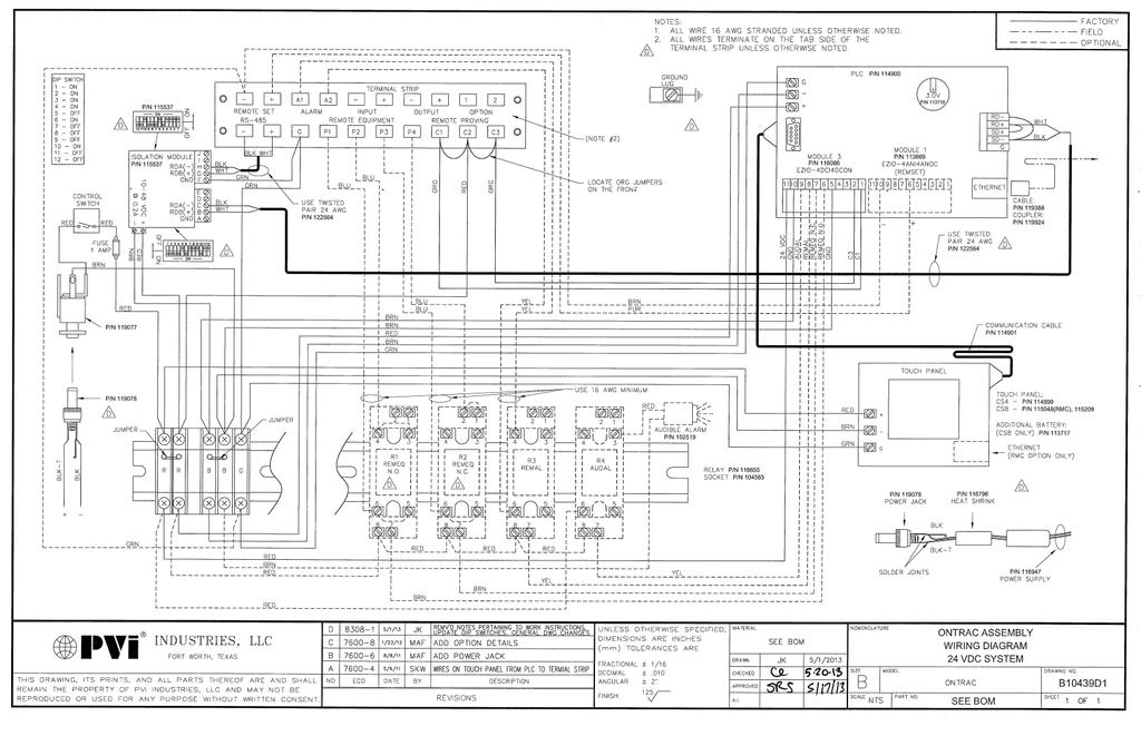
38
EOS INTERFACE GUIDE AND POINTS LIST For EOS BTCII Firmware Version J1239D-570 and newer
 Installation and interface must be performed by a qualified controls technician. IMPORTANT: THIS MANUAL CONTAINS INFORMATION REQUIRED FOR INSTALLATION, INTERFACE AND CONFIGURATION OF THIS EQUIPMENT. READ
ModSync Sequencing System Installation & Operation Manual. For use with Fulton Steam Boilers.
 ModSync Sequencing System Installation & Operation Manual For use with Fulton Steam Boilers. Revision 3.0 8/21/2008 - 2 - Table of Contents Introduction Page 4 Features Page 4 Sequence of Operation Page
WATER HEATER ELECTRONIC CONTROLLER USER MANUAL
 WATER HEATER ELECTRONIC CONTROLLER USER MANUAL UPPER LED READOUT LED ICONS LOWER LED READOUT PVI INDUSTRIES, LLC - Fort Worth, Texas 76111 - Web www.pvi.com - Phone 1-800-433-5654 Page 1 / 7 PV500-40 03/17
User s Manual. TIGER S EYE E-Series Mark V Jockey. TIGERFLOW Systems, Inc Mint Way Dallas, Texas
 User s Manual TIGER S EYE E-Series Mark V Jockey TIGERFLOW Systems, Inc. 4034 Mint Way Dallas, Texas 75237 214-337-8780 www.tigerflow.com TABLE OF CONTENTS Introduction... 4 Sequence of Operation... 5
Carbon Monoxide Transmitter
 Introduction The CO Transmitter uses an electrochemical sensor to monitor the carbon monoxide level and outputs a field-selectable 4-20 ma or voltage signal. The voltage signal may also be set to 0-5 or
RC-112 Two Speed Heat Pump 3 Stage Heat / 2 Stage Cool With Energy Efficient Control
 O M N I S T A T ELECTRONIC COMMUNICATING THERMOSTAT Installation Manual RC-112 Two Speed Heat Pump 3 Stage Heat / 2 Stage Cool With Energy Efficient Control Document Number 13I00-5 November, 1997 CONTENTS
Tri-Stack Smart System
 Tri-Stack Smart System TM Notes & Warnings - The protection provided by this equipment may be impaired if it is not used in the manner specified herein. - Ensure all wiring meets applicable national and
F PC and AO OUTPUT BOARDS INSTRUCTION MANUAL. Blue-White. Industries, Ltd.
 F-2000 PC and AO OUTPUT BOARDS INSTRUCTION MANUAL Blue-White R Industries, Ltd. 500 Business Drive Huntington Beach, CA 92649 USA Phone: 714-89-8529 FAX: 714-894-9492 E mail: sales@blue-white.com or techsupport@blue-white.com
Models NFPA 1221-A, NFPA 1221-B Public Safety DAS Annunciator Panel. Revision E 61117
 Models NFPA 1221-A, NFPA 1221-B Public Safety DAS Annunciator Panel Revision E 61117 CAUTION: (Read This First) This panel has been designed to make it nearly bullet proof to mistakes made when wiring
K-Controller Brochure.qxp_ Controller Brochure 2/27/17 3:03 PM Page 4 Versa IC Platform
 Versa IC Platform VERSA IC Integrated Control Platform Raypak s VERSA IC combines modulating temperature control, safety limits, and ignition programming into one user- friendly Integrated Control Platform.
HIGH EFFICIENCY FIRETUBE CONDENSING GAS BOILER
 This manual must be left with owner and should be hung on or adjacent to the boiler for reference. US HIGH EFFICIENCY FIRETUBE CONDENSING GAS BOILER MODELS CHS-85 through CHS-399 APPENDIX A CONTROLLER
Two-Channel Gas Controller
 Two-Channel Gas Controller Specifications subject to change without notice. USA 09 Page of DESCRIPTION Highly configurable, UL 0 performance-tested and -certified, and wall-mounted gas monitor; continuously
Control manual. Series. Gas-fired direct vent Cast iron boilers. Control adjustment and Operation instructions
 KNCT2-808 KN Series Gas-fired direct vent Cast iron boilers Models KN-6, -10, -20 only (HeatNet control firmware edition 45 ) Control manual Control adjustment and Operation instructions Also read and
Lift Station Level Controller
 Lift Station Level Controller Installation and Operation Manual 1 California Motor Controls, Inc. Benicia, CA Table of Contents 1. Features Product Overview... 4-6 Access Security... 7 Optional Features...
DENVER PUBLIC SCHOOLS DESIGN AND CONSTRUCTION STANDARDS This Standard is for guidance only. SECTION IBAS LIGHTING CONTROL
 PART 0 A/E INSTRUCTIONS 0.01 DESIGN REQUIREMENTS A. Minimum lighting control (base scope of work) shall include all corridors. The lighting in all the corridors shall be turned on (if not already on) if
LMS-188-4P-BMS 4 POINT DIGITAL MONITOR/ALARM WITH PROTOCOL CONVERTER OPERATING INSTRUCTIONS
 G LMS 188 4P BMS August, 2018 LMS-188-4P-BMS 4 POINT DIGITAL MONITOR/ALARM WITH PROTOCOL CONVERTER OPERATING INSTRUCTIONS! WARNING: This product can expose you to chemicals including lead, which is known
SCC Inc. Master Panel. Specifications. Document No. TS 2010 February 11, Product Description. Sample Specification
 February 11, 2019 Master Panel Product Description The Master Panel shall provide lead/lag control and time based, automatic rotation of up to eight (8) boilers, when used in conjunction with LMV3 or LMV5
PROCESS & TEMPERATURE UNIVERSAL INPUT DIGITAL METERS
 PROCESS & TEMPERATURE UNIVERSAL INPUT DIGITAL METERS NOVA PD56 Series Thermocouple, RTD, & Process Inputs Universal Power Supply 1-24 VAC Up to 3 Alarm Relays Retransmitting 4-2 ma Output Input Max/Min
GASGUARDIAN Channel Controller OPERATING & INSTALLATION MANUAL
 GASGUARDIAN 2 3 2-Channel Controller OPERATING & INSTALLATION MANUAL GasGuardian 2 3 Operating and Installation Manual Table of Contents General description.... 3 Installation. 3 Locating the GasGuardian-2..
HeatNet Manual Control Adjustment and Operation Instructions for Hydrotherm Firmware Version 2.8
 KN-2/4-CM2-313 42-9452 Cast Iron Condensing Boilers Models KN-2 and KN-4 HeatNet Manual Control Adjustment and Operation Instructions for Hydrotherm Firmware Version 2.8 Also read and follow: KN Boiler
Process & TeMPerATUre UniversAl input DigiTAl MeTers
 Process & TeMPerATUre UniversAl input DigiTAl MeTers nova PD56 series Thermocouple, rtd, & Process inputs Universal Power supply 1-24 va c Up to 3 Alarm relays retransmitting 4-2 ma output input Max/Min
INSTALLATION INSTRUCTIONS
 TT-1343 5/06b INSTALLATION INSTRUCTIONS Original Issue Date: 8/03 Model: Automatic Transfer Switches Equipped with Series 1000 Programmable Controller Market: ATS Subject: Remote Annunciator Kits GM28938-KP1,
B-40/B-41 Modulating Temperature Controller
 INSTALLATION & OPERATING INSTRUCTIONS B-40/B-41 Modulating Temperature Controller For Raytherm Boilers & Water Heaters H2 514-4001 WH2 2100-4001 Catalog No. 5000.70 Effective: 12-21-11 Replaces: NEW P/N
MO n : 12JMC rév A
 CTT8 MO n : rév A Page 2 / 18 MODIFICATIONS Rev. Description Date Checked by Approuved by Z Creation 2012/02/12 JMC LA A First issue 2012/02/14 JMC LA INDEX Page 3 / 18 GENERALITY 4 INTRODUCTION 4 ACCESSORIES
ARGO (Technical Support) 2201 Dwyer Avenue Utica, NY (Corporate Sales) 85 Middle Road
 2201 Dwyer Avenue Utica, NY (Corporate Sales) 85 Middle Road") ARGO (Technical Support) 2201 Dwyer Avenue Utica, NY 13501 (Corporate Sales) 85 Middle Road An ISO 9001-2000 Certified Company Dunkirk, NY 14048 www.argoindustries.com P/N 240005498A, Rev. 1.5 [02/07]
ARGO (Technical Support) 2201 Dwyer Avenue Utica, NY 13501 (Corporate Sales) 85 Middle Road An ISO 9001-2000 Certified Company Dunkirk, NY 14048 www.argoindustries.com P/N 240005498A, Rev. 1.5 [02/07]
GG-2 2-CHANNEL GAS DETECTION CONTROL PANEL. Installation and Operation Manual
 GG-2 2-CHANNEL GAS DETECTION CONTROL PANEL Installation and Operation Manual 2 GG-2 Warning Use this product only in the manner described in this manual. If the equipment is used in a manner not specified
RC-90 / RC-90B Single Stage Heat/Cool Thermostat for Zone Control Systems Installation Instructions
 RC-90 / RC-90B Single Stage Heat/Cool Thermostat for Zone Control Systems Installation Instructions DESCRIPTION The RC-90 is a precision digital thermostat designed for 24 VAC single stage heating and
CTT8 TEMPERATURE MONITOR DEVICE
 INSTRUCTION MANUAL IM302-U v2.3 CTT8 TEMPERATURE MONITOR DEVICE GENERALITY The device of control temperatures CTT8 is used in the control of electric machine, transformer, motor, etc. where it s possible
Table of Contents 1. OVERVIEW SYSTEM LAYOUT SPECIFICATIONS FUNCTION... 11
 Table of Contents 1. OVERVIEW... 3 2. SYSTEM LAYOUT... 4 3. SPECIFICATIONS... 8 3.1 SYSTEM COMPONENTS...9 3.2 PLC INPUTS AND OUTPUTS...9 3.3 FUNCTION KEYS...10 3.4 DEFAULT SET POINTS AND TIMERS...10 4.
Sequence of operation
 Sequence of operation IPS 4000 secondary variable speed control File No: 90.96 Date: february 21, 2013 Supersedes: new Date: new sequence of operation ips 4000 2 list of abbreviations: adj: Field Adjustable
CONsOlIDATOR 4 & 8. MulTI- C h ANNEl CONTROllERs. ConsoliDator 4 Model PD940 ConsoliDator 4 Features. ConsoliDator 8 Features.
 CONsOlIDATOR 4 & 8 MulTI- C h ANNEl CONTROllERs ConsoliDator 4 Model PD940 ConsoliDator 4 Features Four 4-20 Four 4-20 Outputs ConsoliDator 8 Features Eight 4-20 Two 4-20 Outputs Common Features Four Pulse
Halton SAFE / 7.14 user guide and installation instructions
 Halton SAFE / 7.14 user guide and installation instructions VERIFIED SOLUTIONS BY H A LTO N Enabling Wellbeing Table of contents 1 System description 3 2 User Accounts 4 3 Main menu 7 3.1 Main menu - Change
DAP III Zone Master User s Guide
 DAP III Zone Master User s Guide Data Aire, Inc. 230 West BlueRidge Avenue Orange, California 92865 Document Number 600-000-788 March 2010 Revision 1.0 Document # 600-000-788 1 Overview The Data Aire DAP
Beacon 200 Gas Monitor Operator s Manual. Part Number: RK Released: 6/6/08
 Beacon 200 Gas Monitor Operator s Manual Part Number: 71-2102RK Released: 6/6/08 Table of Contents Chapter 1: Introduction.................................................3 Overview.............................................................3
D8024, D9024, D10024 Analog Fire Alarm Control Panels Programming Guide
 System Reset Trou ble Silence Ala rm Silence Manual Ala rm ENTER NO YES Letters Numb ers Keyword Radionics System Reset Trouble Silence Alarm Silence Manual Alarm ENTER NO YES Le ters Numbers Keyw ord
Oxygen (O2) Single-Point Gas Detection System
 Single-Point Gas Detection System") Oxygen (O) Single-Point Gas Detection System DESCRIPTION Wall-mounted gas monitor with built-in oxygen (O) sensor, accepts one analog remote device such as a secondary gas sensor, temperature or humidity
Oxygen (O) Single-Point Gas Detection System DESCRIPTION Wall-mounted gas monitor with built-in oxygen (O) sensor, accepts one analog remote device such as a secondary gas sensor, temperature or humidity
Nitrogen Dioxide (NO2) Single-Point Gas Detection System
 Single-Point Gas Detection System") Nitrogen Dioxide (NO) Single-Point Gas Detection System DESCRIPTION Wall-mounted gas monitor with built-in nitrogen dioxide (NO)/diesel fume gas sensor, accepts one analog remote device such as a secondary
Nitrogen Dioxide (NO) Single-Point Gas Detection System DESCRIPTION Wall-mounted gas monitor with built-in nitrogen dioxide (NO)/diesel fume gas sensor, accepts one analog remote device such as a secondary
OVEN INDUSTRIES, INC.
 OVEN INDUSTRIES, INC. OPERATING MANUAL Model 5C7-252 TEMPERATURE CONTROLLER With PLC Inputs Introduction Thank you for purchasing our controller. The Model 5C7-252 is an exceptionally versatile unit and
Product Data Sheet. Remote Terminals. Features:
 Remote Terminals Product Data Sheet Features: Based around two core products, the Mx- 4010 Remote Display Terminal (RDT) and the fully functional Mx-4020 Remote Control Terminal (RCT). Both remote terminals
Refrigeration Controller Operator s Manual (HRC) PO Box 6183 Kennewick, WA
 PO Box 6183 Kennewick, WA") Refrigeration Controller Operator s Manual (HRC) PO Box 6183 Kennewick, WA 99336 www.jmcvr.com 1-509-586-9893 Table of Contents TABLE OF FIGURES...1 OVERVIEW OF THE HRC CAPABILITIES...2 INSTALLATION AND
Refrigeration Controller Operator s Manual (HRC) PO Box 6183 Kennewick, WA 99336 www.jmcvr.com 1-509-586-9893 Table of Contents TABLE OF FIGURES...1 OVERVIEW OF THE HRC CAPABILITIES...2 INSTALLATION AND
Flopurge TS. Operation Manual
 Flopurge TS Operation Manual Part Number 079-0204 Spectron Gas Control Systems United Kingdom Unit 4, Herald Court, University of Warwick Science Park, Coventry, CV4 7EZ +44 (0)24 7641 6234 sales@spectron-gcs.com
C SINGLE-POINT HEAT-TRACING CONTROL SYSTEM PRODUCT OVERVIEW
 SINGLE-POINT HEAT-TRACING CONTROL SYSTEM PRODUCT OVERVIEW SHIFT TEST SHIFT C910 SERIES ALARM MONITOR CONFIG BACK ENTER PROGRAMMABLE SINGLE POINT HEAT-TRACING CONTROLLER HEAT-TRACING CONTROLLER STATUS ALARM
RPM1600 Series Room Pressure Monitors
 RPM1600 Series Room Pressure Monitors Technical Bulletin LB-RPM1611-0, LB--0 Code No. LIT-12012228 Issued October 2017 Refer to the QuickLIT website for the most up-to-date version of this document. How
CommStat 6. Controller for Redundant HVAC Systems PRODUCT DATA SHEET
 CommStat 6 Controller for Redundant HVAC Systems PRODUCT DATA SHEET General Description The CommStat 6 HVAC controller is designed for controlling up to six redundant air conditioners in an E-House or
Replaceable LED modules. Sleep or unattended mode. Auto-silence and auto-acknowledge
 Replaceable LED modules 11 Alarm Sequences as per ISA-18.1 standard Each channel/window fully field programmable RS232 or RS485 MODBUS-RTU communication Repeat relay for each window and multifunction relays
200i/KN2, KN4 Firmware Revision Sheet
 200i/KN2, KN4 Firmware Revision Sheet Revision 2.9 Special Release 1- November 2013 1. Added an external boiler Failsafe feature. The J6 Analog Output can be used to enable a SSR which can be used to enable
TYPE CM-2201 NELSON SINGLE POINT CIRCUIT MANAGEMENT SYSTEM
 2 Line, 16 Characters/row LCD Display Temperature Input Range -50 C to +500 C -58 F to + 932 F Enclosure NEMA Type 4X Current Rating 30A max (resistive load only) Ambient Temperature -40 C to + 40 C -40
Electro-Sentry. Users Manual
 Electro-Sentry Users Manual 2. To view an individual point, e.g. Speed just touch that point and it will display a graph showing the 45 min. of activity. Viewing a Leg: 1. Touch the desired leg, e.g. East
Public Safety DAS Annunciator Panel
 Public Safety DAS Annunciator Panel 120 VAC Models: 1221-A, 1221-B, 1221-C Revision D 91117 48 VDC Models: 1221-A-48, 1221-B-48, 1221-C-48 24 VDC Models: 1221A-24, 1221-B-24, 1221-C-24 CAUTION: (Read This
ELECTRONIC COMMUNICATING THERMOSTAT
 O M N I S T A T ELECTRONIC COMMUNICATING THERMOSTAT Installation Manual RC-81 Single Stage Heat/Cool Real Time Pricing System Document Number 13I00-2 January, 1997 Copyright 1997 Home Automation, Inc.
RC-101 Heat Pump Real Time Pricing System 2 Stage Heat / 1 Stage Cool
 O M N I S T A T ELECTRONIC COMMUNICATING THERMOSTAT Installation Manual RC-101 Heat Pump Real Time Pricing System 2 Stage Heat / 1 Stage Cool Document Number 13I00-4 January, 1997 Copyright 1997 Home Automation,
SLATE. Base Module INSTALLATION INSTRUCTIONS R8001A1001
 SLATE Base Module R8001A1001 INSTALLATION INSTRUCTIONS Scan for more information Application SLATE brings configurable safety and programmable logic together into one single platform. The platform can
RSC 1000 User Manual. Rev /25/16
 RSC 1000 User Manual Rev 2.2 10/25/16 CRITICAL APPLICATIONS DISCLAIMER QUEST CONTROLS PRODUCTS ARE NOT INTENDED OR AUTHORIZED FOR USE IN ANY APPLICATION THAT REQUIRES FAIL-SAFE OPERATION, OR ANY SYSTEM
THERMAL BUILDING SOLUTIONS EN-TraceTekTTSIM1A-IM-H /16
 TraceTek TTSIM-1A TraceTek Sensor Interface Module with Relay Installation/OPERATION Instructions Approvals and Certifications TYPE NM General Signaling Equipment 76LJ Only AC versions are UL listed and
Operating & Maintenance Manual. Alert-4 Ethernet LCD Master Alarm
 Operating & Maintenance Manual Alert-4 Ethernet LCD Master Alarm w w w. a m i c o. c o m Contents User Responsibility 4 Introduction 4 Features 5 Description of the Alarm 5 Shipment Details 5 The Alarm
Instruction Bulletin
 Instruction Bulletin 435-54-26A 9/99 Monroe, NC, USA MODEL 98 Digital Temperature Controller For Medium Voltage Transformers Class 3, 4 Retain for future use. NOTICE Read these instructions carefully and
96% AFUE Efficiency CONDENSING RESIDENTIAL GAS BOILERS CONTROL WITH ADVANCED USER FEATURES MODELS FROM 80,000 TO 285,000 BTU/HR
 CONDENSING RESIDENTIAL GAS BOILERS CONTROL WITH ADVANCED USER FEATURES MODELS FROM 80,000 TO 285,000 BTU/HR 5:1 FIRING RATE MODULATION LESS THAN 20 ppm NOx DIRECT VENT FLEXIBILITY TO 100 FEET 96% AFUE
PACSystems* RX3i. Thermocouple Input Module, 12 Channels, IC695ALG412. GFK-2578B October 2011
 October 2011 PACSystems* RX3i Thermocouple Input Module, 12 Channels, IC695ALG412 The PACSystems * Thermocouple Input module IC695ALG412 provides twelve isolated differential thermocouple input channels.
EasyTronic III MANUAL SERVICE
 rev.6 EasyTronic III MANUAL SERVICE General characteristics: Power supply 24 Vac ±15% Max consumption at 24Vac 300mA Relay outputs 6 Maximum relay current 8 A res. Serial standard RS232 2 Serial standard
MODEL FPT-130 SINGLE POINT FREEZE PROTECTION HEAT TRACE CONTROL
 TRACON MODEL FPT-130 SINGLE POINT FREEZE PROTECTION HEAT TRACE CONTROL TABLE OF CONTENTS FPT 130 Overview... 2 Installation... 3 Power Source and Load Connections... 4 Temperature Sensor... 5 External
Memcom Emergency Telephone
 Memcom Emergency Telephone Installation Guide Ref No. 450 900 (GB) Version 2 + + Simple wiring for quick installation + + Integrated LCD display shows you what you have programmed + + All code based programming
Module Features are-configurable, no module jumpers to set
 December 2011 PACSystems* RX3i Isolated Thermocouple Input Module, 6 Channels, IC695ALG306 Isolated Thermocouple Input Module, 12 Channels, IC695ALG312 Isolated Thermocouple Input module IC695ALG306 provides
Pioneer-R16 Gas Monitor Operator s Manual
 Pioneer-R16 Gas Monitor Operator s Manual Edition 7/2/97 RKI INSTRUMENTS, INC RKI Instruments, Inc. 33248 Central Ave, Union City, CA 94587 (510) 441-5656 Chapter 1: Description About the Pioneer-R16 Gas
Pump-Down Controller MODEL 4052
 Pump-Down Controller 4-20mA Input/Scalable Output Seal Fail Monitoring Duplex Pump Alternation Hand-Off-Auto Controls Dual Run-time Meters RS-485/Modbus Communications DESCRIPTION The Model 4052 Pump-Down
User Manual. Dryer Controller M720
 User Manual Dryer Controller M720 Hardware version 1.00 Software version 1.00 Preliminary version Manual M720 Dryer controller Page 1 of 42 Document history Preliminary version: - Created in April, 2009
EKC 347 Liquid Level Controller REFRIGERATION AND AIR CONDITIONING. Manual
 EKC 347 Liquid Level Controller REFRIGERATION AND AIR CONDITIONING Manual Contents Introduction...3 Valve compatibility...3 Features...3 Application examples...3 Ordering...3 Operating the EKC 347...4-5
C SINGLE-POINT HEAT-TRACING CONTROL SYSTEM. product overview
 C910-485 SINGLE-POINT HEAT-TRACING CONTROL SYSTEM product overview ALARM SHIFT TEST C910 SERIES MONITOR CONFIG BACK ENTER PROGRAMMABLE SINGLE POINT HEAT-TRACING CONTROLLER STATUS ALARM OUTPUT The DigiTrace
LC6000 Controller used with MULTI-TEC Wall Mount Units Specification Sheet & Application Guide
 LC6000 Controller used with MULTI-TEC Wall Mount Units Specification Sheet & Application Guide FEATURES OF THE LC6000 CONTROLLER Control up to 14 units with a single LC6000 controller. Complete control
Power Flame Incorporated
 Power Flame Incorporated SUGGESTED SPECIFICATION FOR MODEL NVC ULTRA LOW NOx GAS BURNERS SUB 9 PPM NOx THE POWER TO MANAGE ENERGY 2001 South 21st Street, Parsons, Kansas 67357 Telephone: 620-421-0480,
Better Design, Better Control, Better Systems.
 Product Catalog Better Design, Better Control, Better Systems. At tekmar Control Systems, we believe the indoor comfort of a building depends on the performance of its heating, ventilating & air conditioning
CELLTROL II BIOREACTOR CONTROL SYSTEM OPERATIONS MANUAL
 Operation Manual Celltrol II Bioreactor Control System Page 1 of 33 Table of Contents 1) Introduction... 3 1.1) Scope of Document... 3 1.2) Control System Overview... 3 1.3) Introduction to Celltrol II...
SERIES VAC Microprocessor-Based Direct Spark Ignition Control with Inducer Blower Relay FEATURES APPLICATIONS SPECIFICATIONS DESCRIPTION
 R SERIES 35-61 24 VAC Microprocessor-Based Direct Spark Ignition Control with Inducer Blower Relay F-35-61 August 2015 FEATURES Safe start with DETECT-A-FLAME flame sensing technology Custom pre-purge
EXPERT TRI-STAR. Temperature controller. User s Manual
 Temperature controller r s Manual WARNINGS The warranty can be void if this product is used in a manner not specified by the manufacturer. Every effort has been made to ensure that this manual is complete,
T M. User Manual. MarinaGuard. Ground Fault Monitoring Panel For Marina Shore Power
 T M User Manual MarinaGuard Ground Fault Monitoring Panel For Marina Shore Power NAE1095810 / 03.2013 T M Bender Inc. USA: 700 Fox Chase Coatesville, PA 19320 Toll-Free: 800-356-4266 Phone: 610-383-9200
SCC Inc. TS Series. Technical Instructions. Document No. TS 1000 June 25, TS Touchscreen Kits. Description. Touchscreen
 TS Touchscreen Kits for use with LMV3, LMV5 and RWF Controls June 25, 2018 Touchscreen Description Plate Kit Enclosure TS series touchscreen kits provide a human machine interface (HMI) with a Siemens
UltraLITE Model ELU Centralized Emergency Lighting Inverter 4.2 KW- 5 KW
 12/23/16 Rev 9 UltraLITE Model ELU General Specification 4.2 KW to 5 KW UltraLITE Model ELU Centralized Emergency Lighting Inverter 4.2 KW- 5 KW 1.0 General General Specification This specification describes
CommStat 4. Controller for Redundant Telecom HVAC Systems PRODUCT DATA SHEET. Features and Benefits
 CommStat 4 PRODUCT DATA SHEET Controller for Redundant Telecom HVAC Systems General Description The CommStat 4 is an HVAC controller designed specifically for controlling two redundant air conditioners,
D A R A - 4. Data Aire Relay Auto-Changeover
 D A R A - 4 Data Aire Relay Auto-Changeover WARNING: If adding the DARA-4 panel to existing units that did not include a DARA-4 panel when originally purchased it will be necessary to add a relay or relays.
2017 MacroAir Technologies Toll Free: Fax:
 2017 MacroAir Technologies Toll Free: 866 668 3247 Fax: 909 890 2313 www.macroairfans.com 1 Table of Contents Caution & Safety... 2 Fan Network Ordering... 3 Controller Dimensions... 4 Controller Components...
*IG1583EW* Aurora Touch UPC Kit Instruction Guide. Aurora Touch UPC Kit Instruction Guide
 Aurora Touch UPC Kit Instruction Guide For use in single compressor water-to-air equipment utilizing fi rmware UPCSWASTD01-01 Aurora Touch UPC Kit Instruction Guide *IG1583EW* IG1583EW 08/14 Aurora Touch
CM3500 Controller - ClimateMaster DOAS Water-Source Heat Pumps - Rev.: 7 Oct, 2008B
 2 CM3500 Controller - ClimateMaster DOAS Water-Source Heat Pumps - Rev.: 7 Oct, 2008B CAUTION CAUTION - ONLY TRAINED, QUALIFIED PERSONNEL SHOULD INSTALL AND/OR SERVICE CLIMATEMASTER EQUIPMENT. SERIOUS
Suggested Specification: Benchmark 1.5 Low NOx Gas-Fired Hydronic Boiler(s)
") Furnish and install as shown on AERCO International plans and operation and maintenance manuals, with all applicable codes and authorities having local, state and federal jurisdiction, Benchmark Series
Furnish and install as shown on AERCO International plans and operation and maintenance manuals, with all applicable codes and authorities having local, state and federal jurisdiction, Benchmark Series
TTSIM-2 TRACETEK SENSOR INTERFACE MODULE WITH LCD AND RELAY INSTALLATION/OPERATION INSTRUCTIONS
 TTSIM-2 TRACETEK SENSOR INTERFACE MODULE WITH LCD AND RELAY INSTALLATION/OPERATION INSTRUCTIONS GENERAL INFORMATION Please read these instructions and keep them in a safe place. These instructions must
LMV52 Control. Specifications. Document No. LV February 3, Product Description. Sample Specification
 LMV52 Control Product Description February 3, 2017 The LMV52 is a microprocessor-based burner management system with matching system components for the control and supervision of forced draft burners.
INSTALLATION MANUAL AND OPERATING INSTRUCTIONS
 AMB4/AMB8 MULTIPLE BOILER SEQUENCERS INSTALLATION MANUAL AND OPERATING INSTRUCTIONS ARGO (Technical Support) 2201 Dwyer Avenue Utica, NY 13501 (Corporate Sales) 85 Middle Road An ISO 9001-2000 Certified
Single Point Freeze Protection Heat Trace Control TRACON MODEL FPT 130 Installation and Operation Manual
 We manage heat MANUAL Single Point Freeze Protection Heat Trace Control TRACON MODEL FPT 130 Installation and Operation Manual 1850 N Sheridan Street South Bend, Indiana 46628 (574) 233-1202 or (800) 234-4239
Tempered Water Logic Control OPERATION l TROUBLE SHOOTING
 Tempered Water Logic Control OPERATION l TROUBLE SHOOTING English For MPE Multiple Chiller Units Control Panel TEMPERED WATER SYSTEMS L-2199 Rev. 20080223 Revision: L-2199 20101104 *** IMPORTANT NOTICE
Service Manual Models: 1.0, 1.3, and 1.5
 AWX2-SER_100160837_2000000360_Rev F Service Manual Models: 1.0, 1.3, and 1.5 LOW LEAD CONTENT WARNING This manual must only be used by a qualified heating installer / service technician. Read all instructions,
MEGA. cal electronic gas alarm. Installation, Operation, and Maintenance Instructions. Part No Rev. D Pg.
 WARD OXYGEN Installation, Operation, and Maintenance Instructions MEGA medical electronic gas alarm MEGA WARD MEGA medical electronic gas alarm WARD POWER SUPPLY Medical Electronic Gas Alarm OXYGEN SYSTEM
Hydronic & HVAC Control Systems
 tekmar 218 Full Line Catalog Hydronic & HVAC Control Systems HVAC Multi-Staging Alternative Energy Zoning Snow Melting Setpoint tekmarcontrols.com tekmarcontrols.com Better Design, Better Control, Better
Flostop TS D7E and A8E. Operation Manual
 Flostop TS D7E and A8E Operation Manual United Kingdom Spectron Gas Control Systems Ltd, Unit 4, ATU1, University of Warwick science Park, Coventry, +44 (0) 24 7641 6234 sales@spectron-gcs.com Germany
TWLC - Tempered Water Logic Controller. The Intelligent Control
 TWLC - Tempered Water Logic Controller The Intelligent Control Chiller Controls Features: Up to six (6) stages: individual board for each stage maximizes redundancy. Menu driven access and programming.
La Marche Manufacturing Company Option 46 Series. Digital Combined Accessory Package. Installation and Operation Manual
 La Marche Manufacturing Company www.lamarchemfg.com Option 46 Series Digital Combined Accessory Package Installation and Operation Manual This manual is subject to change without notice. You may obtain
UNC100 Integra Manual
 UNC100 Integra Manual New Generation Building Security July 30, 2014 V1.2 Copyright Notice Copyright 1995-2014 by All rights reserved Worldwide. Printed in Canada. This publication has been provided pursuant
Pump-Up Controller MODEL 4062
 Pump-Up Controller 4-20mA Input/Scalable Output Seal Fail Monitoring Duplex Pump Alternation Hand-Off-Auto Controls Dual Run-time Meters RS-485/Modbus Communications DESCRIPTION The Model 4062 Pump-Up
TEMON 4-C. Doc. N MO-0368-ING TEMPERATURE MONITOR DEVICE TYPE TEMON 4-C OPERATION MANUAL. Microener- Copyright 2010 FW 2.1 Date Rev.
 TEMPERATURE MONITOR DEVICE TYPE TEMON 4-C OPERATION MANUAL Microener- Copyright 2010 FW 2.1 Date 01.12.2008 Rev. 0 1. Generality 3 2. Introduction 3 3. Accessories and Options 3 4. Installation 3 5. Connection
ZX1e ZX2e ZX5e. Document No Issue 01 user manual
 ZX1e ZX2e ZX5e Document No. 996-130 Issue 01 user manual MORLEY-IAS ZX2E/ZX5E Fire Alarm Control Panels Table of Contents 1 INTRODUCTION... 4 1.1 NOTICE... 4 1.2 WARNINGS AND CAUTIONS... 4 1.3 NATIONAL
Table of Contents SECTION PAGE
 Table of Contents SECTION PAGE SECTION 1 INTRODUCTION................... 1.1 Description.............................. 1.2 Features................................ 1.3 Models.................................
Qualifies for up to $ 1500 Energy Tax Credit! CONDENSING RESIDENTIAL GAS BOILERS CONTROL WITH ALL NEW, ADVANCED USER FEATURES
 CONDENSING RESIDENTIAL GAS BOILERS CONTROL WITH ALL NEW, ADVANCED USER FEATURES 5 FLOOR-STANDING AND 5 WALL-MOUNT MODELS FROM 50,000 TO 285,000 BTU/HR FIRING RATE MODULATION TO 5:1 LESS THAN 20 ppm NOx
DSGH. Radiation-Based Detector with GEN2000 Electronics for Density Measurement QUICK REFERENCE GUIDE
 DSGH Radiation-Based Detector with GEN2000 Electronics for Density Measurement QUICK REFERENCE GUIDE Revision History Revision History Version of manual Description Date 1.0 Initial release 051025 1.1