Instructors: Contact information. Don Reynolds Doug McGee Factory Tech Support
|
|
|
- Kerry Davidson
- 6 years ago
- Views:
Transcription
1 Contact information Instructors: Don Reynolds Doug McGee Factory Tech Support


2 Product Improvements for 2017
3 Todays Objectives Job Site Information Sheets Low Ambient Kits Evacuation Air Flow Saturation Temperatures Superheat Sub Cooling Metering Devices Troubleshooting the refrigeration system Why Compressors Fail

4 /8 3/ ft
5 IO-709F LAKT Low Ambient Kit The following accessories must be installed on all condensers and heat pumps when equipped with low ambient kits. Crankcase heater must be installed if not factory installed. Hard start kit for single phase units. (See Spec Sheet for Accessories) TXV kit installed on indoor evaporator coil, if not factory installed. FSK01A - Freeze protection kit must be installed on indoor coil. Wind buffer must be installed for temperatures below 0 F or areas with high prevailing winds. Wind buffer can be a wall fabricated from wood or masonry material that will prevent the prevailing wind from causing the outdoor fan to rotate. NOTE: When wind buffer is installed, it is necessary to use minimum 4" risers to elevate the unit off of the pad to provide better airflow for moderate and high ambient temperatures. NOTE: These kits are not approved for any 16 and 18 SEER outdoor units that utilize an ECM condenser fan motor. Note: Units equipped with ECM condenser motors are not approved for low ambient installations. 3/17/2017
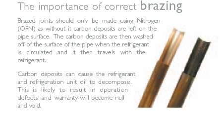
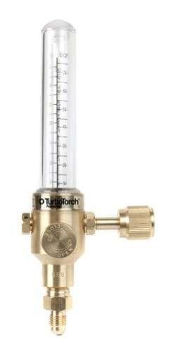
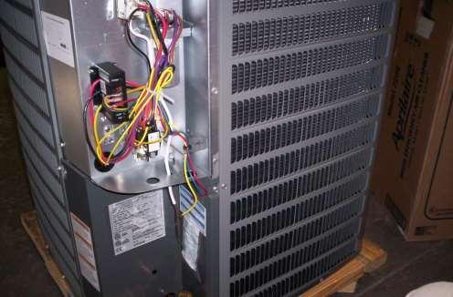
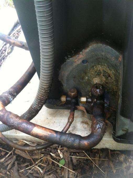
6 Brazing

7


8 Evacuation microns between each mark
9 How Do You Get The Water Out? We Boil It We Lower the System Pressure To A Point That Water Boils At Ambient Temperatures
10 Pressure VS. Boiling Point Physics 101 As Pressure Decreased - The Boiling Point Decreases
11 Speed Of Evacuation Size Of System Complexity Of Piping System Components Oil Separators Accumulators Valves Ambient Temperature Size Of Pump How You are Hooked Up To the System High & Low Side Size Of Hoses Access Fitting?


12 One Very Important Rule No test is valid if the airflow is not Correct No Pressures No temperatures No Current Draws
13 Things you are going to Learn Today Air Flow
14
 Measure the static pressure of the supply air duct (positive")
15 Taking Duct Statics (Checking External Static Pressure) ESP With clean filters in the furnace. Measure the static pressure of the return air at the inlet of the furnace(negative pressure) Measure the static pressure of the supply air duct (positive pressure) Add the two reading together for total external static pressure
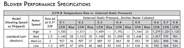
16 Goodman/Amana Blower Chart

17
18 Air Flow A properly operating air conditioning system both cools ( a sensible heat process) and dehumidifies ( a latent heat process) the air. For example given a 2 ton unit a percentage of the total capacity of the system is utilized to cool the air while the remaining percentage of the total capacity is used to dehumidify the air. Properly controlling both the temperature (sensible heat) and the humidity (latent heat) will provide the optimum comfort levels.
19
20 Adding Up The Numbers 750 cfm 22,400 X 0.78 = 17,472 btu s sensible heat 22,400-17,472 = 4,928 btu s latent heat 900 cfm 23,200 X 0.83 = 19,256 btu s sensible heat 23, = 3944 btu s latent heat
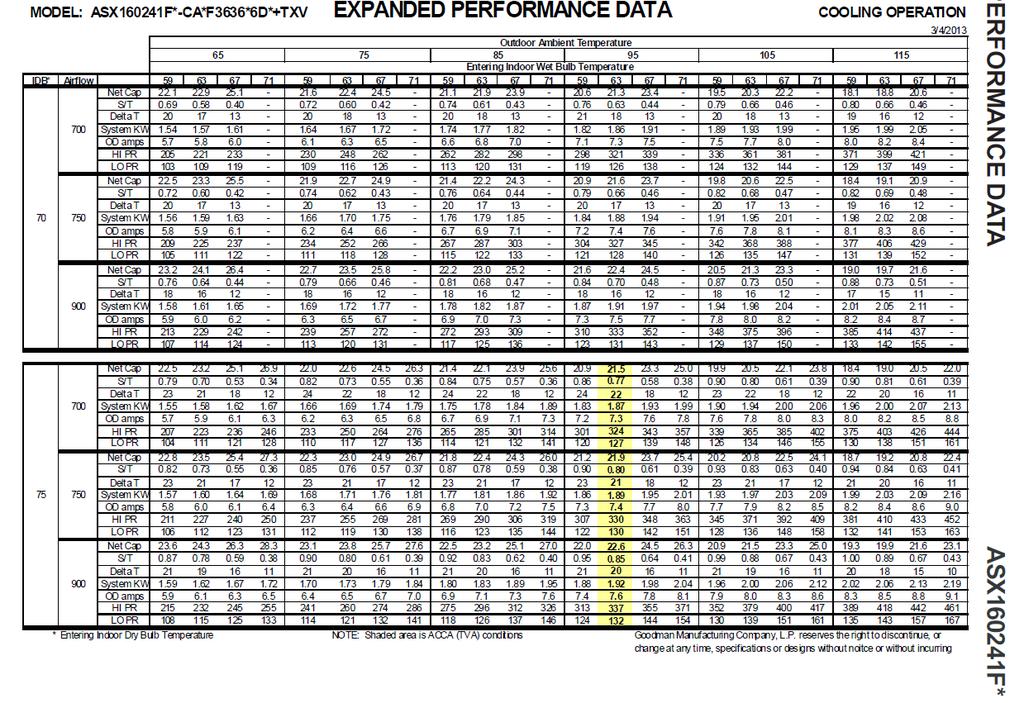
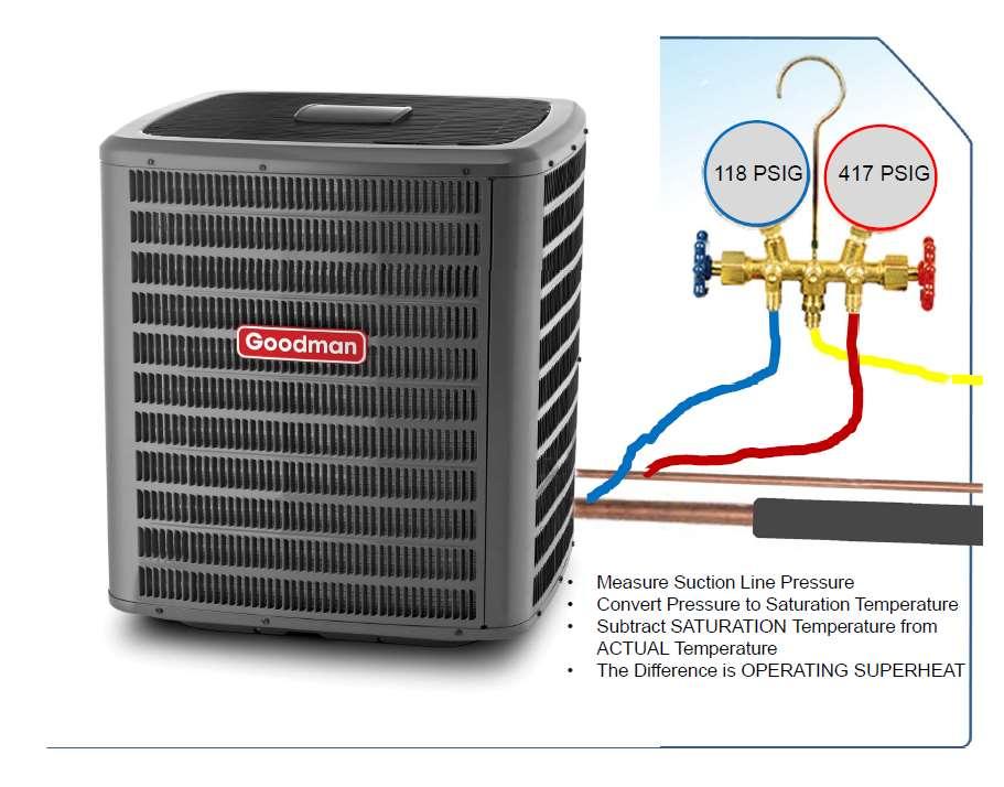
21 Saturation Temperature The temperature of the liquid or vapor, where any heat is add or removed, a change of state takes place

22 Converting Pressure to Saturation For any given pressure refrigerants have a saturation temperature The suction pressure will convert to the temperature of the refrigerant leaving the metering device The liquid pressure converts to the saturation temperature of the refrigerant condensing in the condenser Temperature
23

24
25

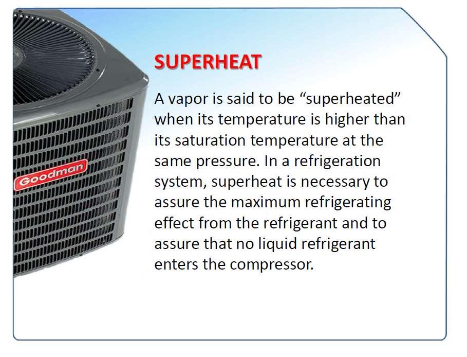
26 Superheat (Evaporator) The amount of heat added to the refrigerant after it changes to the vapor state is called Super Heat.
27

28

29 Pressure Temperature Chart Suction line temperature 55 degrees #120 = 41 degrees Superheat 14 degrees

30 Superheat Chart
31
32
33
34
35
36
37
38
")
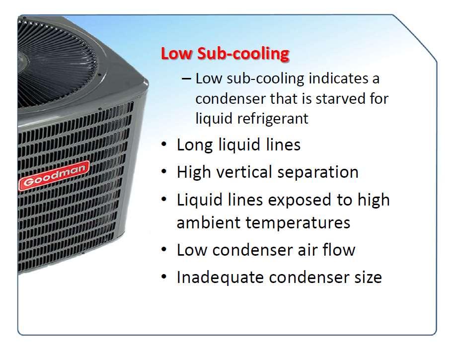
39 Sub Cooling (Condenser)
40
41
42
43 # Liquid Line Temp 111 Sub Cooling 9
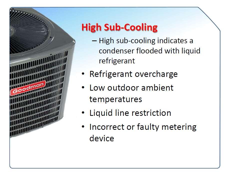
44 Goodman/Amana/Daikin TXV Systems Should read 8 degrees + / - 1 degree of Sub-cooling for Single Stage Units. Superheat 8 degrees Two Stage systems should read 5 to 7 degrees of subcooling in Low Stage. Superheat 7-9 degrees
45
46
47 Metering Devices Note: Always size the piston to the outdoor condenser ( piston will come attached to the outdoor unit)

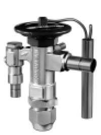
48 TXV Valve Operation 49

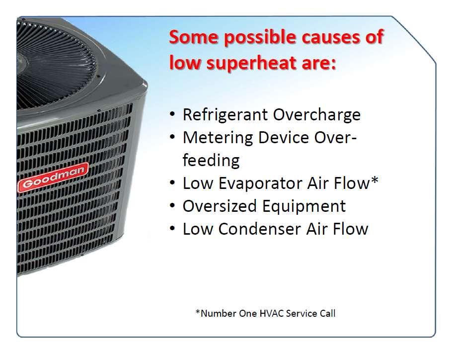
49 Symptoms of a Restricted (Underfeeding)Metering Device Restrictions in the metering device will prevent the evaporator coil from receiving the proper amount of refrigerant Low Suction Pressure High Super Heat High sub cooling
50 Overfeeding Metering Device When an overfeeding condition is present, the suction side of the system operates in a flooded state. The high side of the system operates in a starved state. The suction pressure will be high The super heat will be low The head pressure will be low The subcooling will be low
51
52 Symptoms of Low System Charge Fixed or TXV Metering Device Low System Pressures High Superheat Low sub-cooling Low Amperage on compressor The compressor will also run hot Because of low suction pressure the evaporator may form a coating of ice on it If the system is slightly low on charge the TXV may open enough to maintain adequate suction pressure and superheat, but the head pressure will still be lower than normal and the sub-cooling will also be low If the system charge is very low the system will have the same symptoms as a fixed metering device
53 Symptoms of a Over Charged Unit Higher than normal head pressure Higher than normal suction pressure Low Superheat High Subcooling High Amperage on Compressor Liquid Floodback Compressor noise A system with a TXV valve will show the suction pressure and superheat to show normal, because the TXV is trying to throttle back the refrigerant entering the coil. This causes the excess refrigerant to be stored in the condenser which will elevate the head pressures and liquid subcooling levels If the overcharge is severe the suction pressure may increase with low superheat
54 Liquid Line Restrictions Restrictions in the liquid line will prevent the evaporator from receiving the proper amount of refrigerant. The restriction will cause a large pressure drop between the condenser coil and the metering device Liquid line restrictions can be caused by the following restricted filter drier, restricted TXV screen, kinked liquid line or kinked or bent U bend on lower portion of condenser coil
55 Symptoms of a Liquid Line Restriction Low Suction Pressure High head pressure High Subcooling High superheat Low compressor amperage Frosting or sweat of the liquid line or liquid line filter drier

56 Suction Line Restrictions The suction line is a much more sensitive refrigerant line, because vapor instead of liquid flows through it. A restricted suction line will cause low suction pressures and head pressures and a starved compressor and condenser. A starved compressor will lead to low compressor amp draw because of the lightened load..
57 Restricted Suction Line Since a suction line restriction starves the compressor of refrigerant, causing the flow of refrigerant to decrease through the system. This in turn will cause high superheat. Subcooling will be normal to a bit high, because the refrigerant will not be circulated very fast causing the liquid refrigerant to back up into the condenser

58 Evaporator Circuit Restrictions Restrictions within the evaporator coil will cause the system to exhibit the same operating characteristics as a restricted metering device
59 Identifying Evaporator Circuit Restrictions Systems running with a restriction in the evaporator coil will have a low suction pressure along with a high superheat The liquid pressure will initially be low If refrigerant is added at this time, the liquid pressure will rise but the suction pressure will remain low. If subcooling is checked at this time, it will be high. This is because excess refrigerant is being stored in the condenser
60 Checking For Non Condensables Air, nitrogen, and other foreign gasses present in a refrigerant system are referred to as non condensables since they will not condense into a liquid at pressures encountered in a refrigeration system These gases will accumulate in the condenser coil and take up valuable condenser coil circuits

61 Identifying Condenser Circuit Restrictions The restriction in the circuit will cause a corresponding drop in refrigerant temperature. Therefore, the circuit with the restriction will have refrigerant leaving the circuit at a temperature much colder than the other circuits

62 Most compressors fail because of System Problems Compressors
63 Causes of Mechanical Compressor Failures: Refrigerant Flood back Flooded Starts Slugging Compressor Overheating Loss of Oil
64 Liquid Flood Back Restricted air flow Plugged filters Dirty evaporator coil Non operating blower motor Ductwork Wrong fan speed Overcharge TXV overfeeding Too large of piston
65 Liquid Refrigerant Flood back Floodback is defined as liquid refrigerant returning to the compressor during the running cycle. The resulting damage is determined by the type of compressor-- refrigerant cooled or air cooled. We will look at them separately.


66
67 Refrigerant Migration Refrigerant migration occurs anytime refrigerant and oil are in contact with each other and the compressor is not operating. Refrigerant vapor in the crankcase condenses and is absorbed by the oil. Liquid refrigerant in the evaporator vaporizes and moves to the crankcase as a vapor.
68 Slugging Slugging is the result of significant quantities of liquid refrigerant, oil, or both getting into the compressor. The cause is usually refrigerate migration

69 Overheating High Compression Ratios High Return Gas Temperature Lack of External Cooling

70 Loss of Oil Failures Poor Piping Improper Traps Loss of Charge Short Cycling Low Loads Pressurized Crankcase in Suction-Cooled Compressors

71 Questions?
Table of Contents. Service Procedures. Service Procedures. Measuring Superheat (4) Measuring Subcooling (5) Airflow Calculation (6-8)
 Measuring Subcooling (5) Airflow Calculation (6-8)") Table of Contents Refrigeration Cycle Service Procedures Measuring Superheat (4) Measuring Subcooling (5) Airflow Calculation (6-8) Solving Problems Identifying Low System Charge (9-11) Identifying High
Table of Contents Refrigeration Cycle Service Procedures Measuring Superheat (4) Measuring Subcooling (5) Airflow Calculation (6-8) Solving Problems Identifying Low System Charge (9-11) Identifying High
Service Step by Step Trouble-Shooting Check-List
 WARNING: Only Data Aire trained technician or experience technicians should be working on Data Aire Equipment. Protect yourself at all times and work safe. Date: Dates at the job site: From: to Job#: Serial#:
Otherwise, you can continue reading the file on the following pages.
 If you d like to be able to print this file out to study off-line or use on the job, a printable version is available for an administrative fee of $3.97 USD. To download the unlocked file, click here.
SECTION 5 COMMERCIAL REFRIGERATION UNIT 21 EVAPORATORS AND THE REFRIGERATION SYSTEM UNIT OBJECTIVES 3/22/2012 REFRIGERATION
 SECTION 5 COMMERCIAL REFRIGERATION UNIT 21 EVAPORATORS AND THE REFRIGERATION SYSTEM UNIT OBJECTIVES After studying this unit, the reader should be able to Define high-, medium-, and low-temperature refrigeration.
AIR CONDITIONING. Carrier Corporation 2002 Cat. No
 AIR CONDITIONING Carrier Corporation 2002 Cat. No. 020-016 1. This refresher course covers topics contained in the AIR CONDITIONING specialty section of the North American Technician Excellence (NATE)
SECTION 7 AIR CONDITIONING (COOLING) UNIT 40 TYPICAL OPERATING CONDITIONS
 UNIT 40 TYPICAL OPERATING CONDITIONS") SECTION 7 AIR CONDITIONING (COOLING) UNIT 40 TYPICAL OPERATING CONDITIONS UNIT OBJECTIVES After studying this unit, the reader should be able to Explain what conditions will cause the evaporator pressure
SECTION 7 AIR CONDITIONING (COOLING) UNIT 40 TYPICAL OPERATING CONDITIONS UNIT OBJECTIVES After studying this unit, the reader should be able to Explain what conditions will cause the evaporator pressure
SECTION 7 AIR CONDITIONING (COOLING) UNIT 40 TYPICAL OPERATING CONDITIONS UNIT OBJECTIVES
 UNIT 40 TYPICAL OPERATING CONDITIONS UNIT OBJECTIVES") SECTION 7 AIR CONDITIONING (COOLING) UNIT 40 TYPICAL OPERATING CONDITIONS UNIT OBJECTIVES After studying this unit, the reader should be able to Explain what conditions will cause the evaporator pressure
SECTION 7 AIR CONDITIONING (COOLING) UNIT 40 TYPICAL OPERATING CONDITIONS UNIT OBJECTIVES After studying this unit, the reader should be able to Explain what conditions will cause the evaporator pressure
Warm Case Troubleshooting Guide 9/18/2014
 Introduction Warm cases can be caused by various problems which require thorough troubleshooting. Begin the investigation with questions to store personnel asking for information such as when the last
To accomplish this, the refrigerant fi tis pumped throughh aclosed looped pipe system.
 Basics Refrigeration is the removal of heat from a material or space, so that it s temperature is lower than that of it s surroundings. When refrigerant absorbs the unwanted heat, this raises the refrigerant
For an administrative fee of $9.97, you can get an un-locked, printable version of this book.
 The System Evaluation Manual and Chiller Evaluation Manual have been revised and combined into this new book; the Air Conditioning and Refrigeration System Evaluation Guide. For an administrative fee of
The Saturation process
 SOUTH METROPOLITAN TAFE WA The Saturation process Dennis Kenworthy 8/5/2016 A student study guide to measuring and interpreting the saturation process of refrigeration and air-conditioning equipment System
Thomas J Kelly. Fundamentals of Refrigeration. Sr. Engineering Instructor Carrier Corporation. August 20, Page number: 1.
 Thomas J Kelly Sr. Engineering Instructor Carrier Corporation August 20, 2003 1 SESSION OBJECTIVES At the conclusion of this session you should be able to: 1. Describe the basics principles of refrigeration
Calhoon MEBA Engineering School. Study Guide for Proficiency Testing Refrigeration
 Calhoon MEBA Engineering School Study Guide for Proficiency Testing Refrigeration 1. To prevent an injury when working with refrigerants, what safety precautions are necessary? 2. When halogens are in
SECTION 7 AIR CONDITIONING (COOLING) UNIT 41 TROUBLESHOOTING
 UNIT 41 TROUBLESHOOTING") SECTION 7 AIR CONDITIONING (COOLING) UNIT 41 TROUBLESHOOTING UNIT OBJECTIVES After studying this unit, the reader should be able to Select the correct instruments for checking an air conditioning unit
SECTION 7 AIR CONDITIONING (COOLING) UNIT 41 TROUBLESHOOTING UNIT OBJECTIVES After studying this unit, the reader should be able to Select the correct instruments for checking an air conditioning unit
Math. The latent heat of fusion for water is 144 BTU s Per Lb. The latent heat of vaporization for water is 970 Btu s per Lb.
 HVAC Math The latent heat of fusion for water is 144 BTU s Per Lb. The latent heat of vaporization for water is 970 Btu s per Lb. Math F. to C. Conversion = (f-32)*(5/9) C. to F. Conversion = C * 9/5 +
HEAT PUMPS. Carrier Corporation GT72-01 Cat. No
 HEAT PUMPS Carrier Corporation 2003 GT72-01 Cat. No. 020-018 1. This refresher course covers topics contained in the HEAT PUMPS specialty section of the North American Technician Excellence (NATE) certification
SECTION 8 AIR SOURCE HEAT PUMPS UNIT 43 AIR SOURCE HEAT PUMPS
 SECTION 8 AIR SOURCE HEAT PUMPS UNIT 43 AIR SOURCE HEAT PUMPS UNIT OBJECTIVES After studying this unit, the reader should be able to Describe the operation of reverse-cycle refrigeration (heat pumps) Explain
Use this Construction/HVAC Glossary to answer the questions below.
 www.garyklinka.com Page 1 of 21 Instructions: 1. Print these pages. 2. Circle the correct answers and transfer to the answer sheet on the second last page. 3. Page down to the last page for the verification
Energy Use in Refrigeration Systems
 2012 Rocky Mountain ASHRAE Technical Conference Energy Use in Refrigeration Systems PRESENTED BY: Scott Martin, PE, LEED AP BD+C Objectives Understand mechanical refrigeration terms Describe how heat is
Refrigeration Systems and Accessories
 As with the Chapter Review Tests and the Final Exam, the tests your understanding of the materials underlying the learning objectives. After you ve reviewed your answers to the Chapter Review Tests, try
HEAT PUMPS. Carrier Corporation GT72-01A Cat. No
 HEAT PUMPS Carrier Corporation 2004 GT72-01A Cat. No. 020-018 Table of Contents AIR CONDITIONING AND HUMAN COMFORT...1 AIR CONDITIONING THERMODYNAMICS...2 EFFICIENCY RATINGS...8 TEMPERATURE-PRESSURE...10
PL Series Premier Indoor Plenum Coils
 IM-PLC-0667392-04 April 2016 PL Series Premier Indoor Plenum Coils Installation Instructions GENERAL ADP evaporator coils are designed for use with condensing units or heat pump units. These instructions
Class 1: Basic Refrigera0on Cycle. October 7 & 9, 2014
 Class 1: Basic Refrigera0on Cycle October 7 & 9, 2014 Refrigeration Cycle 4 key components needed in a basic refrigera0on cycle: 1. Compressor 2. Condenser 3. Evaporator 4. Metering Device Compressor Compressor
HVAC Systems What the Rater Needs to Know in the Field CALCS-PLUS
 HVAC Systems What the Rater Needs to Know in the Field This presentation used CASE* studies from the following *CASE Copy And Steal Everything HVAC Systems - What the Rater Needs to Know in the Field This
Refrigeration and Air Conditioning
 Refrigeration and Air Conditioning 1. Pick up the wrong statement. A refrigerant should have (a) Tow specific heat of liquid (b) high boiling point (c) high latent heat of vaporisation (d) higher critical
Residential Piping and Long Line Guideline
 AC / HP R-410A Refrigerant Systems Single-Stage, Two-Stage and Variable Speed Models Residential Piping and Long Line Guideline TABLE OF CONTENTS Safety Considerations... 2 Definitions... 2 Introduction...
How to Diagnose a TXV Failurek
 How to Diagnose a TXV Failurek There has been much written and many jokes made about the misdiagnosis of TXV (Thermostatic expansion valves) and rightly so. This article will cut straight to the point
Mortex INSTALLATION INSTRUCTIONS AIR CONDITIONING & HEAT PUMP INDOOR COILS
 Mortex INSTALLATION INSTRUCTIONS AIR CONDITIONING & HEAT PUMP INDOOR COILS INTRODUCTION Please note that HUD Manufactured Home Construction and Safety Standard Section 3280.714, paragraph (a) and subparagraph
Cased Aluminum Coils "Dedicated Upflow / Downflow" Convertible to horizontal with separately purchased kit
 18-AD32D1-3 Cased Aluminum Coils "Dedicated Upflow / Downflow" Convertible to horizontal with separately purchased kit Upflow models: 4PXCAU24BS3HAA 4PXCBU24BS3HAA 4PXCBU30BS3HAA 4PXCCU30BS3HAA 4PXCBU36BS3HAA
Superheat charging curves for technicians
 This website requires certain cookies to work and uses other cookies to help you have the best experience. By visiting this website, certain cookies have already been set, which you may delete and block.
PARALLEL RACK SYSTEM INSTALLATION & OPERATIONS MANUAL With Master Rack Compressor Sequencer
 PARALLEL RACK SYSTEM INSTALLATION & OPERATIONS MANUAL With Master Rack Compressor Sequencer 5/16 Rev. A 57-02509 2 Contents INTRODUCTION... 4 WARNING LABELS AND SAFETY INSTRUCTIONS... 5 PS SERIES PARALLEL
APPLICATION DATA SHEET
 APPLICATION DATA SHEET General Piping Recommendations and Refrigerant Line Length for Split-System Air Conditioners and Heat Pumps GENERAL GUIDELINES This Split-System (Air Conditioning Condensing/Heat
Experienced Worker Assessment Blueprint HVAC - Heating, Ventilation and Air Conditioning
 Blueprint HVAC - Heating, Ventilation and Air Conditioning Test Code: 0144 / Version: 02 Specific Competencies and Skills Tested in this Assessment: Electricity Demonstrate understanding of basic AC/DC
Checking the Charge on a Heat Pump in the Winter
 Checking the Charge on a Heat Pump in the Winter When you ask many people nowadays how to check the charge on a heat pump during low outdoor temps they will say that you need to weigh in and weigh out
Everything You. NEED to KNOW. TXV does this by keeping the coil supplied
 Everything You NEED to KNOW About TXVs } With the higher SEER air conditioners, technicians need to reacquaint themselves with thermostatic expansion valves B Y A L M A I E R Before the 13 SEER minimum
Determining Real Time Performance of Residential AC Systems. Presented at the RESNET Conference San Antonio, TX February 28, 2006
 Determining Real Time Performance of Residential AC Systems Presented at the RESNET Conference San Antonio, TX February 28, 2006 Bill Spohn testo, Inc. testo Worldwide 100 90 80 70 60 50 40 30 20 10 0
INSTALLATION INSTRUCTIONS TXV Horizontal Slab Coils WLSH
 TXV Horizontal Slab Coils WLSH These instructions must be read and understood completely before attempting installation. It is important that the Blower and Duct System be properly sized to allow the system
INSTALLATION & OPERATING INSTRUCTIONS FOR CEILING MOUNT AIR HANDLERS AC SERIES
 C US INSTALLATION & OPERATING INSTRUCTIONS FOR CEILING MOUNT AIR HANDLERS AC SERIES Made in the USA by: Goodman Manufacturing Company, L.P. I0-240B 2550 North Loop West, Suite 400, Houston, TX 77092 www.goodmanmfg.com
SECTION 2 SAFETY, TOOLS AND EQUIPMENT, SHOP PRACTICES UNIT 10 SYSTEM CHARGING
 SECTION 2 SAFETY, TOOLS AND EQUIPMENT, SHOP PRACTICES UNIT 10 SYSTEM CHARGING UNIT OBJECTIVES After studying this unit, the reader should be able to Describe how refrigerant is charged into systems in
SECTION 5 COMMERCIAL REFRIGERATION UNIT 22 CONDENSERS UNIT OBJECTIVES UNIT OBJECTIVES 3/22/2012
 SECTION 5 COMMERCIAL REFRIGERATION UNIT 22 CONDENSERS UNIT OBJECTIVES After studying this unit, the reader should be able to explain the purpose of the condenser in a refrigeration system. describe differences
G Series. G Series Air Coils Installation ti Manual ENCASED/UNCASED AIR COILS. Geothermal/Water Source Heat Pumps R-410A Refrigerant 2-5 Ton
 G Series ENCASED/UNCASED AIR COILS Geothermal/Water Source Heat Pumps R-410A Refrigerant 2- Ton Dimensional Data G Series Air Coils Installation ti Manual Installation Information Maintenance IM1018AG1
Installation Instructions
 25HHA4 Performance Series Heat Pump with Puron Refrigerant 1-1/2 to 5 Nominal Tons Installation Instructions Fig. 1-25HHA4 A07532 SAFETY CONSIDERATIONS Improper installation, adjustment, alteration, service,
Installation Instructions
 Performance Series Heat Pumps with PURONr Refrigerant 1 --- 1/2 to 5 Nominal Tons Installation Instructions Fig. 1 --- A07532 NOTE: Read the entire instruction manual before starting the installation.
Air Conditioning Components
 Air Conditioning Components Agenda AC Components Compressor & Clutch Condenser Receiver-drier or Accumulator Expansion Valve or Orifice Tube Evaporator Compressor 2 primary purposes Increase pressure &
Pressure Enthalpy Charts
 Pressure Enthalpy Charts What is a p-h Diagram? A p-h diagram is a diagram with a vertical axis of absolute pressure and a horizontal axis of specific enthalpy. "Enthalpy is the amount of energy in a substance
INSTALLATION INSTRUCTIONS TXV Horizontal Duct Coils EHD
 TXV Horizontal Duct s EHD These instructions must be read and understood completely before attempting installation. It is important that the Blower and Duct System be properly sized to allow the system
Entry Level Assessment Blueprint Heating, Ventilation and Air Conditioning (HVAC)
") Entry Level Assessment Blueprint Heating, Ventilation and Air Conditioning (HVAC) Test Code: 3080 / Version: 01 Specific Competencies and Skills Tested in this Assessment: Electricity Demonstrate understanding
Entry Level Assessment Blueprint Heating, Ventilation and Air Conditioning (HVAC) Test Code: 3080 / Version: 01 Specific Competencies and Skills Tested in this Assessment: Electricity Demonstrate understanding
HVAC/R Refrigerant Cycle Basics
 HVAC/R Refrigerant Cycle Basics This is a basic overview of the refrigeration circuit and how it works. It isn t a COMPLETE description by any means, but it is designed to assist a new technician or HVAC/R
REFRIGERANT RECOVERY Log Book
 REFRIGERANT RECOVERY Log Book R E F R I G E R A N T L O G 1) Policy 2) Troubleshooting 3) Condensers Replaced 4) Compressors Replaced 5) Appliance Disposal 6) Accidental Venting 7) R22 NEW 8) R22 Recover
Application Guide. Refrigerant Piping Manual for Small Split Cooling and Heat Pump Systems SS-APG006-EN
 Refrigerant Piping Manual for Small Split Cooling and Heat Pump Systems I Refrigerant Piping II Microchannel Units III High Rise Systems Trane and American Standard Heating & Air Conditioning Split Systems
Sporlan Valve Division Parker Hannifan/CIC Group
 www.parker.com/cic Sporlan Valve Division Parker Hannifan/CIC Group Matt McGrath, SW Regional Sales Manager Bob Dolan, Sales Engineer - Atlanta www.parker.com/cic Why Discuss TEVs Today? Expansion Valves
Technical Standards for the Air Conditioning and Heat Pump Professional BPI STANDARDS
 Technical Standards for the Air Conditioning and Heat Pump Professional BPI STANDARDS THE SYMBOL OF EXCELLENCE FOR HOME PERFORMANCE CONTRACTORS VERSION 1.1, FEBRUARY 2003 TABLE OF CONTENTS: TECHNICAL STANDARDS
R Series Cooling Manual
 Mini Duct Heating and Air Conditioning Indoor Air Quality Systems R Series Cooling Manual Includes: RPM-E-50 Cooling Module RPM-E-0 Cooling Module RPM-E-00 Cooling Module Manufactured By Energy Saving
Eclipse Technical Training CME686 CME810 CP686 CP886 CP1086
 Eclipse Technical Training CME686 CME810 CP686 CP886 CP1086 In This Presentation What Eclipse is Components and their functions Installation Operation Maintenance Service Diagnosis The Eclipse System The
WineZone Ceiling Mount Ductless Split 15
 WineZone Ceiling Mount Ductless Split 15 Requires an HVAC technician to install and charge with R-22 refrigerant. Easy to install. Unit plugs into wall outlet. Industrial grade unit for longer life. Indoor
INSTALLATION INSTRUCTIONS TXV Horizontal Duct Coils EHD
 TXV Horizontal Duct s EHD These instructions must be read and understood completely before attempting installation. It is important that the Blower and Duct System be properly sized to allow the system
SEVEN STEPS TO EFFECTIVE PRE- SEASON COOLING CHECKUPS
 SEVEN STEPS TO EFFECTIVE PRE- SEASON COOLING CHECKUPS by Dennis Kalchuk While temperatures are still tolerable, it's time to prepare your customers' systems to deal with the blasts of summer heat and humidity
CAUTION. Check Equipment and Job Site. Clearance Requirements. Unpack Unit
 INSTALLATION IMPORTANT: Effective January 1, 2015, all split system and packaged air conditioners must be installed pursuant to applicable regional efficiency standards issued by the Department of Energy.!
Condensing Unit Installation and Operating Instructions
 Bulletin WCU_O&I 01 June 2003 Condensing Unit Installation and Operating Instructions WCU Air Cooled Condensing Unit Table of Contents Section 1. Section 2. Section 3. Section 4. Section 5. Section 6.
SA Series Start up Report
 SA Series Start up Report Important To ensure warranty validation and continued customer satisfaction, complete this form and return it to Desert Aire immediately after start-up. Validation of this report
Some of these procedures need to be performed to conform to requirements of the Clean Air Act.
 Leak Detection, Recovery, Evacuation and Charging Four basic service procedures used to repair and maintain a mechanical refrigeration system are leak detection, evacuation, recovery, and refrigerant charging.
Data Aire, Inc. reserves the right to make design changes for the purpose of product improvement or to withdraw any design without notice.
 Data Aire, Inc. reserves the right to make design changes for the purpose of product improvement or to withdraw any design without notice. Table of Contents 1.0 Introduction 1.1 Inspection...4 1.2 Description...4
HVAC Fundamentals & Refrigeration Cycle
 HVAC Fundamentals & Refrigeration Cycle Change of State of Water & the Refrigeration Cycle Change of State Water The Basic Refrigeration Cycle Types of DX Systems The Chilled water System The Cooling Tower
A/C-HEATER SYSTEM - MANUAL
 A/C-HEATER SYSTEM - MANUAL 1986 Isuzu Trooper II 1986 A/C-HEATER SYSTEM Isuzu A/C-Heater Systems - Manual P UP, Trooper II * PLEASE READ THIS FIRST * CAUTION: When discharging air conditioning system,
Electrical Problems. Fuse(s) blow or circuit breaker trips. Does the unit use circuit breakers or fuses? Replace with correct fuse(s)
 blow or circuit breaker trips. Does the unit use circuit breakers or fuses? Replace with correct fuse(s)") Electrical Problems Fuse(s) blow or circuit breaker trips Does the unit use circuit breakers or fuses? Fuse(s) Circuit breakers Are the fuses dual element time delay? Is the circuit breaker HACR rated?
Electrical Problems Fuse(s) blow or circuit breaker trips Does the unit use circuit breakers or fuses? Fuse(s) Circuit breakers Are the fuses dual element time delay? Is the circuit breaker HACR rated?
Installation Manual BCS 1000/1500
 Installation Manual BCS 1000/1500 Supplies Needed for Installation 1. Double insulated refrigerant line set. 2. 1/4 copper water supply 3. 1/4 condensate vinyl drain tube/tube clamps 4. Provide 120V 15A
BASIC HEAT PUMP THEORY By: Lloyd A. Mullen By: Lloyd G. Williams Service Department, York Division, Borg-Warner Corporation
 INTRODUCTION In recent years air conditioning industry technology has advanced rapidly. An important byproduct of this growth has been development of the heat pump. Altogether too much mystery has surrounded
12 In Row. Installation Manual. MISSION CRITICAL Air Conditioning Systems. ClimateWorx International Inc.
 MISSION CRITICAL Air Conditioning Systems 12 In Row Installation Manual ClimateWorx International Inc. 14 Chelsea Lane, Brampton, Ontario, Canada L6T 3Y4 2 Table of Contents Table of Contents... 3 Site
Heating, Ventilation & Air Conditioning (HVAC)
") Job Ready Assessment Blueprint Heating, Ventilation & Air Conditioning (HVAC) Test Code: 3045 / Version: 01 Measuring What Matters Specific Competencies and Skills Tested in this Assessment: Electricity
Job Ready Assessment Blueprint Heating, Ventilation & Air Conditioning (HVAC) Test Code: 3045 / Version: 01 Measuring What Matters Specific Competencies and Skills Tested in this Assessment: Electricity
REFRIGERATION CYCLE Principles of Mechanical Refrigeration Level 2: Cycle Analysis
 REFRIGERATION CYCLE Principles of Mechanical Refrigeration Level 2: Cycle Analysis Technical Development Program Technical Development Programs (TDP) are modules of technical training on HVAC theory, system
RSES Technical Institute Training Manual 2 72 hours, 72 NATE CEHs, 7.2 CEUs
 Lesson 1 - Trade Tools Explain the importance of using proper tools and test instruments. List the various types of wrenches and describe their use. Describe the proper procedures for bending, flaring,
Installation Instructions
 PREFERREDT SERIES AIR CONDITIONER WITH PURONR REFRIGERANT 1-1/2 TO 5 NOMINAL TONS Installation Instructions Fig. 1 --- 538A NOTE: Read the entire instruction manual before starting the installation. TABLE
UP TO 17.5 SEER / 13.5 EER / 9.5 HSPF HEAT PUMP ENVIRONMENTALLY BALANCED R- 410A REFRIGERANT 2 THRU 5 TONS SPLIT SYSTEM
 EFFICIENT UP TO 17.5 SEER / 13.5 EER / 9.5 HSPF HEAT PUMP ENVIRONMENTALLY BALANCED R- 410A REFRIGERANT 2 THRU 5 TONS SPLIT SYSTEM 208/230 Volt 1- phase REFRIGERATION CIRCUIT S 2- stage scroll compressors
Series 6, Vertical Floor-Mount Units
 MISSION CRITICAL Air Conditioning Systems Series 6, Vertical Floor-Mount Units Installation Manual ClimateWorx International Inc. 14 Chelsea Lane, Brampton, Ontario, Canada L6T 3Y4 2 Table of Contents
Motor Vehicle Air Conditioning (MVAC) System operation and the refrigerant cycle
 System operation and the refrigerant cycle") Motor Vehicle Air Conditioning (MVAC) System operation and the refrigerant cycle At Sea level water boils at 212⁰ F R 134a boils at 15⁰ F At Sea level R 134a boils at 15⁰ F At 30 psig R 134a boils at 35⁰
Motor Vehicle Air Conditioning (MVAC) System operation and the refrigerant cycle At Sea level water boils at 212⁰ F R 134a boils at 15⁰ F At Sea level R 134a boils at 15⁰ F At 30 psig R 134a boils at 35⁰
PRESSURE-ENTHALPY CHARTS AND THEIR USE By: Dr. Ralph C. Downing E.I. du Pont de Nemours & Co., Inc. Freon Products Division
 INTRODUCTION PRESSURE-ENTHALPY CHARTS AND THEIR USE The refrigerant in a refrigeration system, regardless of type, is present in two different states. It is present as liquid and as vapor (or gas). During
Event #1 Brazing. In this event you will demonstrate how to:
 Event #1 Brazing Read and interpret the refrigerant circuit drawing Follow all normal safety procedures Use proper brazing techniques to join tubing, fittings, and components Return all tools, instruments,
REFRIGERANT ON-VEHICLE INSPECTION AC 14
 14 REFRIGERANT ON-VEHICLE INSPECTION 1. INSPECT REFRIGERANT PRESSURE WITH MANIFOLD GAUGE SET (a) This is a method to specify trouble areas by using a manifold gauge set. Read the manifold gauge pressure
Installation Instructions
 CNPVP CNRVP Cased N Coils Upflow --- Downflow Heating --- Cooling Installation Instructions NOTE: Read the entire instruction manual before starting the installation. TABLE OF CONTENTS PAGE SAFETY CONSIDERATIONS...
Section 1: Theory of Heat Unit 3: Refrigeration and Refrigerants
 Section 1: Theory of Heat Unit 3: Refrigeration and Refrigerants Unit Objectives After studying this chapter, you should be able to: Discuss applications for high-, medium-, and low temperature refrigeration.
Installation Instructions
 CNPVP CNRVP Cased N Coils Upflow --- Downflow Heating --- Cooling Installation Instructions NOTE: Read the entire instruction manual before starting the installation. TABLE OF CONTENTS PAGE SAFETY CONSIDERATIONS...
10/4/2013. The Changing State of Refrigerants
 10/4/2013 The Changing State of Refrigerants Refrigerant Chemistry CFC = Chlorofluorocarbon Rapid phase-out Stopped U.S. production in 1996 R-11, R-12, R-113, R-114, R-500, R-502 HCFC = Hydrochlorofluorocarbon
INSTALLATION GUIDE. 4AC 14* ASA1 SERIES R-410a CONDENSING UNITS R-410A ATTENTION, INSTALLER! ATTENTION, USER!
 4AC 14* ASA1 SERIES R-410a CONDENSING UNITS INSTALLATION GUIDE R-410A ATTENTION, INSTALLER! After installing the system, show the user how to turn off electricity to the unit. Point out control and switch
R Series Cooling Modules
 R Series Cooling Modules Models RCM/RPM 50 RCM 70 RM 100 RM 140 Manufactured By Energy Saving Products Ltd. Standard ESP 105.03 Refrigerant Modules (RCM/RM) Fig. 02 - Mounting brackets The cooling coil
B. A. T. Basic Appliance Training
 B. A. T. Basic Appliance Training BASIC REFRIGERATION presented by Phil Whitehead Program Objective The objective of this program is to give you some of the basic elements that are essential to understanding
Product Data PH13(N,P)R FEATURES AND BENEFITS. SPLIT SYSTEM HEAT PUMP For Use With R Refrigerant 1---1/2 TO 5 TONS ( )
R FEATURES AND BENEFITS. SPLIT SYSTEM HEAT PUMP For Use With R Refrigerant 1---1/2 TO 5 TONS ( )") (N,P)R SPLIT SYSTEM HEAT PUMP For Use With R --- 22 Refrigerant 1---1/2 TO 5 TONS (018 --- 060) Product Data *Units factory---shipped with no refrigerant. Dry nitrogen charge only. FEATURES AND BENEFITS
(N,P)R SPLIT SYSTEM HEAT PUMP For Use With R --- 22 Refrigerant 1---1/2 TO 5 TONS (018 --- 060) Product Data *Units factory---shipped with no refrigerant. Dry nitrogen charge only. FEATURES AND BENEFITS
MYSTICOOL Max Valve System with Xstream and A.R.M.E.D. Technology Service & Installation Instructions Page 1
 Page 1 WHY should I install the MYSTICOOL Max Valve System? XDX is more efficient, saving on power consumption. Use of XDX system decreases defrost cycles. XDX maintains more consistent product temperatures,
INSTALLATION INSTRUCTIONS TXV Coils EDM, EDD, EDA
 TXV Coils EDM, EDD, EDA These instructions must be read and understood completely before attempting installation. It is important that the Blower and Duct System be properly sized to allow the system to
Installation Instructions
 Evaporator Coil A Coil --- Cased Multipoise NOTE: Read the entire instruction manual before starting the installation. TABLE OF CONTENTS PAGE SAFETY CONSIDERATIONS... 1 INTRODUCTION... 1 INSTALLATION...
TECHNICAL GUIDE DESCRIPTION SPLIT-SYSTEM AIR-COOLED CONDENSING UNITS. HA300, HB360, HB480 & HB thru 50 NOMINAL TONS (50 Hz)
") DESCRIPTION These units are completely assembled, piped and wired at the factory to provide one-piece shipment and rigging. Each unit is pressurized with a holding charge of refrigerant-22 for storage
DESCRIPTION These units are completely assembled, piped and wired at the factory to provide one-piece shipment and rigging. Each unit is pressurized with a holding charge of refrigerant-22 for storage
Installation Manual for ETI AVS Series and NON-ETI Air Handlers with SC or SD Compressor Units and R-410A Refrigerant
 EarthLinked TXV Kit Installation Manual for ETI AVS Series and NON-ETI Air Handlers with SC or SD Compressor Units and R-410A Refrigerant CONTENTS PAGE Pre-Installation 3 Air Handler Conversion 4 System
Installation Instructions
 24AHA4 Performance Series Air Conditioner with Puron Refrigerant 1-1/2 to 5 Nominal Tons Installation Instructions Fig. 1-24AHA4 A07532 SAFETY CONSIDERATIONS Improper installation, adjustment, alteration,
XSTREAM Valve System With A.R.M.E.D. Technology Service & Installation Instructions Page 1
 Page 1 WHY should I install the XSTREAM Valve System? XDX is more efficient, saving on power consumption. Use of XDX system decreases defrost cycles. XDX maintains more consistent product temperatures,
Installation Instructions
 25HBB, 25HBC Baset Series Heat Pumps with Puronr Refrigerant 1 --- 1/2 To 5 Nominal Tons Installation Instructions NOTE: Read the entire instruction manual before starting the installation. SAFETY CONSIDERATIONS
RTP Technical Bulletin
 RTP Technical Bulletin Category: REFRIGERATION REGISTERED TECHNICIANS PROGRAM Volume 1 Bulletin 2 the information contained in this bulletin contains some important c o n c e p t s regarding pressure/
R Series Cooling Modules
 TM Small Duct High Velocity Heating, Cooling and Indoor Air Quality Systems R Series Cooling Modules Models RCM-50 RCM-70 RM-100 Manufactured By Module-RCM/RM-Series-Installation-Manual-120113 Refrigerant
Technical Training Associates Presents. Commercial Refrigeration Equipment Servicing Part 1
 Technical Training Associates Presents Commercial Refrigeration Equipment Servicing Part 1 By Jim Johnson A Practical Approach To The Fundamentals Of Walk-Ins, Reach-In and, Display Cases: Restaurant,
Basic Principals of Air conditioning By Dr. Esam Mejbil Abed
 REPUBLIC OF IRAQ Ministry of Higher Education & Scientific Research University of Babylon College of Engineering Mechanical Engineering Department Basic Principals of Air conditioning By Dr. Esam Mejbil
INSTALLATION INSTRUCTIONS TXV Coils EBD, EBA
 TXV Coils EBD, EBA These instructions must be read and understood completely before attempting installation. It is important that the Blower and Duct System be properly sized to allow the system to operate
INSTALLATION INSTRUCTIONS TXV Coils EBU, EBA
 TXV s EBU, EBA These instructions must be read and understood completely before attempting installation. It is important that the Blower and Duct System be properly sized to allow the system to operate