REV.01 /
|
|
|
- Annabel May
- 6 years ago
- Views:
Transcription


1 REV.01 /
2 CAUTION! Observe the safety instructions of this installation and maintenance manual before placing the boiler in operation. If an unqualified person carries out installation, adjustment, modification, operation or maintenance of the heating system, this may result in danger to life and limb or property damage. The directions of this installation and maintenance manual must be followed precisely. If you require assistance or further information, contact a qualified installer or an appropriate service provider. The installation and service instructions are a component of the technical documentation and must be handed over to the operator of the heating system. Discuss the instruction in this manual with the owner or operator of the heating system to ensure that they are familiar with all information required for operation of the heating system. 2
3 Contents Information on the boilerplate 4 Boiler dimensions 5 Boiler packaging dimensions 6 Technical parameters 7 Introduction 8 Ensuring safety of equipment and people 9 Operating instructions 9 NOVA series boiler general features 9 Recommended fuel 9 Control and safety devices 10 Thermo-mechanical regulator 10 Regulating hatch 10 Air rosette 11 Chimney Flap 11 Thermometer 11 Putting the boiler into service 11 Checking the boiler before turning it on 11 Filling and draining the heating system 11 Operation and controls 12 Starting a fire 12 Setting outlet water temperature 12 Stoking 12 Overnight heating mode 13 Removing solid combustion residuals 13 Dewing and tarring 13 Boiler shutdown 13 Short-term shutdown 13 Long-term shutdown 14 Important information 14 Boiler repairs 14 Warranty and warranty conditions 14 Boiler delivery 14 Installation instructions 14 Boiler installation General information 14 Heating water requirements 15 Boiler Location 15 Minimum distance 16 Boiler room disposition layout 16 Chimneys and chimney connection Warnings, Flue pipe installation 17 Chimney Height - Section Chart 19 Accumulator tank capacity 20 Transportation and storage 20 Boiler cleaning 21 Flue gas cleaning 21 Ash pan cleaning 22 Head loses 22 Hydraulic connection diagrams 23 Boiler combustion system 24 Air inlet 24 NOVA boiler parts 25 NOVA boiler spare parts lists 26 Troubleshooting 28 Notes 29 Notes 30 3
4 Information on the boilerplate The boiler serial no is shown on the plate which is attached to the backside cover panel of the boiler body. 4
5 Boiler dimensions 5
6 Boiler packaging dimensions Dimensions Case Width Case Length NOVA NOVA NOVA NOVA NOVA Case Height
7 Technical parameters 7
8 Introduction 1. The boiler and all associated equipment must be installed and used in accordance with the installation design, all applicable legal regulations and technical standards and with the manufacturer s instructions. The boiler may be used only for the purpose for which it is intended. 2. The boiler may be installed only in an environment, which it is designed for. If the same person who installs it delivers the boiler to the client, he must give the user also all accompanying boiler documentation (in particular User Guide, Service Book, etc.). Until the boiler is put into service, the original packaging must be kept in case the boiler has to be transported again. 3. After installation, the boiler must be put into operation by a service organization authorized by the manufacturer. 4. The boiler complies with regulations applicable in the European Union. When used in the conditions of countries outside at EU, any deviations from local regulations must be identified and rectified. 5. In the event of a defect call an authorized manufacturer s service organization any unauthorized interference may damage the boiler (and possibly also associated equipment!). 6. The service technician putting the boiler into operation for the first time must show the user the various parts of the boiler and how to control the boiler, with the boiler safety elements, their signals and appropriate user reaction to them, with fundamental parts of the boiler and their controls. If the same person who installs it delivers the boiler to the client, he must make sure that the original packaging is available in case the boiler has to be transported again. 7. Check the delivery for completeness. 8. Check whether the model and type supplied is suitable for the required use. 9. Whenever you are not certain how to control the boiler, study appropriate instructions in this Operation and installation Guide carefully and proceed accordingly. 10. Never remove or damage any markings and signs on the boiler. Keep the original packaging until the boiler has been put into service, in case the boiler has to be transported again. 11. When making any repairs, only original parts must always be used. It is forbidden to make any changes to the boiler s internal installation, or to interfere with it in any way. 12. At the end of its life cycle, the boiler its package and its parts must be disposed of in a way avoiding harm to the environment. 13. The manufacturer disclaims any responsibility for damages caused by the failure to abide by: The conditions stipulated in this Operation and Installation Guide Applicable regulations and standards. Sound installation and operation procedures. Conditions stated in the Warranty Certificate and the Service Book. The conditions stipulated in this Operation and Installation guide Situations might occur in practice, when the following essential precautions must be taken: Shut the boiler down every time when here are any (even temporary) 8
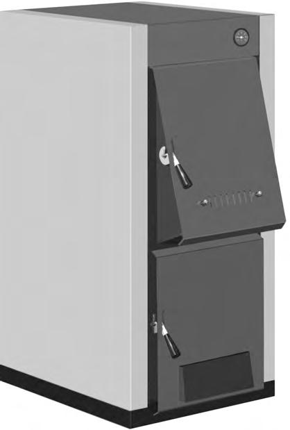
9 Flammable or explosive fumes present on the premises from combustion air are supplied to the boiler (e.g. from paint when painting, laying and spraying molten substances, from gas leakage, etc.). If it is necessary to drain water from the boiler or from the whole system, the water must not be dangerously hot; If there is any leakage from the boiler s heat exchanger, or when the exchanger is clogged up with ice, do not attempt to start up the boiler until normal operating conditions have been restored; Ensuring safety of equipment and people The boiler (and all accessories) complies with the requirements of EN its updates and all relevant European standards. In order to run and operate the boiler in accordance with the purpose for which it is designed in actual conditions of use (hereafter referred to only as use), it is necessary to abide also by additional requirements the most essential ones of which (i.e. those which must not be omitted) are found in the related regulatory documents. In addition to the above-mentioned documents, it is necessary when using the boiler to proceed in accordance with this Operation and Installation guide and the accompanying boiler manufacturer's documentation. Any interference by children, persons under the influence of narcotic drugs, certified persons, etc., when using the boiler, must be prevented. Operating Instructions NOVA Series Boiler General features NOVA series solid fuel fired boiler is designed for heating both residential and industrial buildings. Besides professional installation, precondition for correct functioning of the boiler is the required chimney thrust and correct operation. NOVA series solid fuel fired boiler is designed for heating systems, which are suitable for forced circulation systems only. NOVA series boilers are available in five output series: 20 kw up to 60 kw. Attached to the boiler body are sheet metals covers are fitted on the inside with thermal insulation. To ensure that the boiler functions correctly and runs economically, it is important that its nominal output is equal to the thermal losses of the heated premises. Choosing a boiler of insufficient output will result in inadequate heating of the premises, and thus failure to provide a heating comfort. Choosing a boiler of unnecessarily high output will result in the boiler not running in full output, and as a consequence in tarring and dewing. Recommended fuel Recommended fuels for NOVA boilers are coal, coke and firewood. Optimal coal and coke granularity is mm. Optimal firewood size is logs of diameter mm. Their length will depend on how many kw size. 9
 are shown in the technical data table on page 7. The boiler is stoked manually.")
10 Fuel must be stored in a dry place. To reach the boiler nominal output, water content in firewood must not exceed 20%. Approximate stoking intervals (referred to as burning time) are shown in the technical data table on page 7. The boiler is stoked manually. Please note The boiler is not intended for burning any type of waste. When fitting the safety and the control elements remember to meet the principles of work safety. If replacing of safety device and of thermo mechanical regulator is necessary, please use recommended devices in case of using any other type of the device negotiate with satrom. Functionality of thermo-mechanical output regulator must be checked or inspected bye authorized person once in a year. Control and safety devices Thermo - mechanical regulator It is situated on the outlet from the boiler body. It detects temperature of the hot water and regulates the supply of primary combustion air to underneath the boiler stoker, by opening or shutting a flap situated in the ashtray door. Regulating hatch Changing the hatch position controls the combustion intensity and thus the boiler output. The thermo mechanical regulator is connected with the regulating hatch by chain. The chain is connected to the hatch in such a way that its tension can be set. 1. Regulation Head 2. Arm holder 3. Arm 4. Regulator body 5. Hexagon 6. Pit Fig. 01 Fig. 02 Keep objects away from regulation hatch's front and channels for allowing primary air transfer. 10

11 Air rosette Supply of secondary combustion air is controlled by an air rosette situated in the boiler s stoking door, which has a direct effect on the level of emission. Whether the installation conforms to the design. Whether the boiler has been filled in and is under pressure (on the thermometer), and whether there are any leakage in the heating system; Connection to the chimney - connection must be approved by an authorised chimney sweep (chimney inspection); Chimney flap Fig. 03 Functioning of the heating controls. Please note The service technician must show the user how to control the boiler and enter the date when the boiler was put into service into the warranty certificate. Filling up and draining the heating system Thermometer Fig. 04 Hot water temperature can be checked on a thermometer, which is situated in the upper side boiler cover. The system can only been filled up or topped up with water which meets the parameters specified by EN standards. The water must be clear, colourless, free of suspended particles, oil and chemically corrosive substances, and must not be acidic ( PH factor must be greater than 7.2 ). First of all, the heating system must be thoroughly flushed and all dirt washed out. Please note Putting the boiler into service Fig. 05 Checking the boiler before turning it on Before putting the boiler into operation, the service technician must check: Water in system must not be reduced or put out unless the boiler is in service or under freezing danger. Against freezing anti-freeze liquid can be added in to system water at the rate of % 15. Please note The failure to meet this requirement may lead to the heat exchanger getting clogged up, and the steel block may crack as a result. 11
12 During the heating season, a constant volume of water must be maintained inside the heating system. When topping up water, care must be taken that no air is sucked into the system. Water must never be let out of the boiler or the heating system, unless it is absolutely essential, such as before repairs, etc. Draining water and refilling the system ial, such as before repairs, etc with new water increases the risk of corrosion and formation of incrustation. Please note Filling or topping up water to the heating system must always be done with the boiler cold or cooled down; otherwise the boiler block may crack! Operation and controls Starting a fire Check on the thermometer whether there is enough water in the heating system. Open the shutting valve between the boiler and the heating system. Spread paper on top of the clean stoker and then enough finely chopped wood. Open the flue flap in the chimney adapter and shut the stoking door. Light the paper through the open ashtray door and fully open the regulating flap in the ashtray door. The fire has caught up enough stoke a layer of main fuel on top of the burning firewood. When the fire is powerful enough, stoke more fuel right up to the bottom edge of the stoking door and level it into. Provide an even layer throughout the entire boiler depth. If the fuel suddenly turns into dark red blaze, open partially the secondary air supply rosette in the stoking door. When the flame turns yellow, shut the secondary air supply rosette again. When the boiler has reached the required output, it is suitable to partially shut the flue thrust flap to prevent heat from unnecessarily escaping into the chimney. Do not start the boiler without connecting the boiler to the chimney. Control chimney connections before starting the boiler. Adjust the chimney blow as requested level. If chimney blow is under mentioned levels try not to use the boiler. Setting the outlet water temperature When the required outlet water temperature is say 60 C, heat up the boiler to a temperature for instance 5 C higher than the required temperature of 60 C (measured on the thermometer on the boiler outlet pipe). Then turn the control knob to 65 C and check whether the chain is stretched and the regulating hatch completely shut. This position of the chain and regulating hatch is fine-adjusted y turning the control knob. Then let the regulation process work. When the water temperature drops, the regulating hatch will start opening by the tension applied by the regulator on the chain. When the water temperature suddenly rises, the regulating hatch will start opening. And the hot water temperature on the boiler outlet is controlled. Stoking First shut the regulating hatch; this will shut supply of combustion air into the boiler. Then open the chimney flap completely. Partially open the stoking door and wait until all combustion gases have been sucked from the combustion chamber into the chimney. 12
13 Only then open the stoking door completely and start stoking the boiler. After shutting the stoking door, set the chimney flap again and restore the functioning of the regulating hatch. Boiler doors must not be held open as the boiler is continuously working. Provide a minimum 5 cm gap to be between top point of the fuel and ceiling of stoking chamber when boiler is stoked. Overnight heating mode This mode is used when you want to maintain the fire in the boiler for instance over night. First scrape all ash out of the combustion chamber, with the chimney flap completely opened. Then stoke the boiler with fuel and shut the boiler up completely. Then shut the chimney flap and also almost shut the regulating hatch. This will reduce the chimney thrust and restrict the supply of combustion air. Shut also the secondary air supply rosette in the stoking door. To restore the boiler s required output, just open the chimney flap and partially open the regulating hatch to the required boiler output. Dewing and tarring When starting fire in a cold boiler, water condensates on the walls and runs down into the ash compartment, which may make an impression that the boiler is leaking. This dewing will disappear after the astray has settled on the boilers inside walls. When running the boiler with low water temperature usually below 65 C, or when using damp fuel, water condensates in combustion gases and the condensate runs down the boiler s cold walls. Low temperature heating also reduces the chimney life. Therefore it is recommended to equip the boiler with for instance a four-way blending valve which will ensure that the temperature of return water does not drop below 50 C. Boiler tarring occurs under similar conditions (back of combustion air, the boiler is choking). To prevent dewing and tarring, we recommend you run the boiler at temperatures higher than 65 C and choose a boiler to match the required heating system output. An oversized boiler suffers unnecessarily, because it has to be run at low temperatures. Boiler shutdown We do not recommend that you try to speed up the boiler combustion process. The fuel must burn completely on its own on the stoker. Removing solid combustion residuals Removing and emptying the ashtray situated underneath the stoker in the ash compartment do this. This must be done on a regular basis to prevent ash from accumulating and blocking the supply of air to the combustion chamber from underneath the stoker. Short term shutdown After shutting the boiler down, clean it, remove all combustion residuals, empty the ashtray, clean the stoking door contact surfaces and the ash compartment, and then shut the boiler s stoking door and ash compartment door. 13
14 Long term shutdown When shutting the boiler down for a protracted period of time (heating season end), the boiler must be thoroughly cleaned from all soot and ash sediments, in which dampness accumulates and causes excessive corrosion of the boiler body. Important information An adult person familiar with these operating Instructions may only operate the boiler. Shut the boiler down every time there are any (even temporary) flammable or explosive fumes present on the premises from which combustion air is supplied to the boiler (e.g. From paint when painting, laying and spraying molten substances, from gas leakage, etc.). It is forbidden to light the boiler with explosive substances. It is forbidden to overheat the boiler. At the end of the heating season the boiler, flue and flue adapter, must be thoroughly cleaned. Lubricate all hinges, the flue flap mechanism and other moving. Boiler repairs An authorised service technician or organisation may repair the boiler only. The user or owner may do only normal maintenance and simple replacements of some parts e.g. sealing cords. Please note When repairing the boiler, original parts must always be used. Warranty and warranty conditions NOVA boilers are covered by warranty specified in the warranty certificate, Service book and user and Installation guide (chapter Introduction, Installing the boiler). Boiler delivery NOVA series boilers are supplied completely assembled and functionally tested. The delivery includes: 1. Boiler 2. Operating and Installation Instructions 3. Service Book 4. List of service centres 5. Warranty Certificate 6. Thermo-mechanical output regulator 7. Cleaning brush Installation Instructions Boiler installations General information NOVA boilers must be put into service by an authorised service. A network of authorised service organisations, which meet these conditions, is available for all boiler installations, putting them into service and for warranty repairs. These networks are organised by STECO s agreed distributors outside of Turkey. The boiler is designed to supply heating systems with gauge pressure up to 400 kpa which use water that meets the requirements of related standards (under no circumstances may the water be acidic, i.e. it must have ph>7, and it should have minimum carbon hardness). 14
15 The heating system must be designed in such a way that hot water can circulate all the time through at least some of the radiators. Antifreeze fluids because of their unsuitable properties, we do not recommend to use them. They have a reduced ability to transfer heat, have large volumetric expansion, age and damage rubber components. If under concrete circumstances there is no other option how to reliable prevent. Before final installation, the heating system distribution piping must be flushed several times with pressurised water. In old, already used system, the flushing must be done in opposite direction to the hot water circulation. In new systems, all radiators must be cleaned from conservation material. And rinsed with warm water under pressure. We recommend installing a sludge trap upstream of the boiler (i.e. on hot water return pipe). The sludge trap design should allow emptying in regular intervals, without the need to drain a lot of hot water. The sludge trap may be combined with a filter; however, a filter alone will not provide an adequate protection. Please note System must be connected to open expansion tank for safety reasons. Any valve must not be connected to safety input and safety output lines. For increasing safety of the system, bypass line must be installed on the line between input and output of circulation pumps, as shown in diagrams. By-Pass line's valve must be kept closed as the boiler is working normally. By-Pass line's valve can be used in electricity problems and must be opened if there is a risk of overheating in system water caused by an electricity cut or problem. 15 The pipe used in by-pass line must be at least in the diameter of plumbing systems pipe. UPS (Power Supply Units) can be used for preventing electricity problems. Any problems (malfunctions) caused by boiler clogging with dirt from the heating system and/or malfunctions induced by clogging, are not covered by the boiler warranty. The filter as well as the sludge trap must be checked and cleaned regularly. Heating water requirements Heating water requirements are specified in EN Standards. When the sum of concentrations of calcium and magnesium in the water exceeds 1,8 mmol/l, additional non - chemical treatments preventing lime deposition must be considered (e.g. Magnetic or electrostatic field treatment). Boiler location NOVA boilers can be located both on nonhabitable premises (e.g. in boiler room, cellar, corridor ) and in habitable rooms. The room in which the boiler is located must have a permanent supply of air necessary for the combustion process. The air must be free of halogen hydrocarbons and corrosive vapours, and must not be excessively humid and dusty. The room must be protected against frost, with ambient temperature within the range +5 C to +35 C and relative humidity not exceeding % 80. To comply with fire regulations, the boiler must be installed: On floor constructed of non-flammable material.
16 On a non-flammable material overlapping the boiler footprint by 20 mm on each side and covering the entire depth of the boiler body. If the boiler is installed in a cellar, we recommend putting it on a socket at least 50 mm high, positioning the boiler in the middle. To comply with standards, at least 600 mm manipulation space must be left in front of the boiler. Minimum distance between the back of the boiler and the wall must be also 600 mm, and a free space of at least 600 mm must be left between one side of the boiler and the wall, to allow access to the rear of the boiler. Fuel must not be stacked directly behind on next to the boiler at a distance less than 800 mm. If there are two boilers in the boiler room, no fuel is allowed to be stacked between them. We recommend to keep a minimum distance of 800 mm between the boiler and fuel (Fig. 7), or keep fuel in a room other than the one in which the boiler is installed. Do not put flammable materials on top of the boiler or near the boiler than specified safety distance. Boiler room disposition layout Illustrates minimum distances, which must be kept in order to ensure safe operation of the boiler room and allow manipulations with the boiler, such as cleaning and stoking. The distance between the front of the boiler and the wall should be at least the boiler length L plus 500 mm. Minimum distances between the boiler side and rear should be 800 mm with the distance of the rear also determined by the way the boiler is connected to the chimney. Minimum distance Feed the connector into the flue gas system on a short, ascending path. Avoid deflections, especially those with an angle of 90. Fasten and support connectors sufficiently. Since the flue pipe is only fixed into the flue gas system and push-fitted onto the boiler flue socket, it should be fitted very carefully so that it does not come loose. Only use parts of non - flammable materials for the flue gas system. Fig
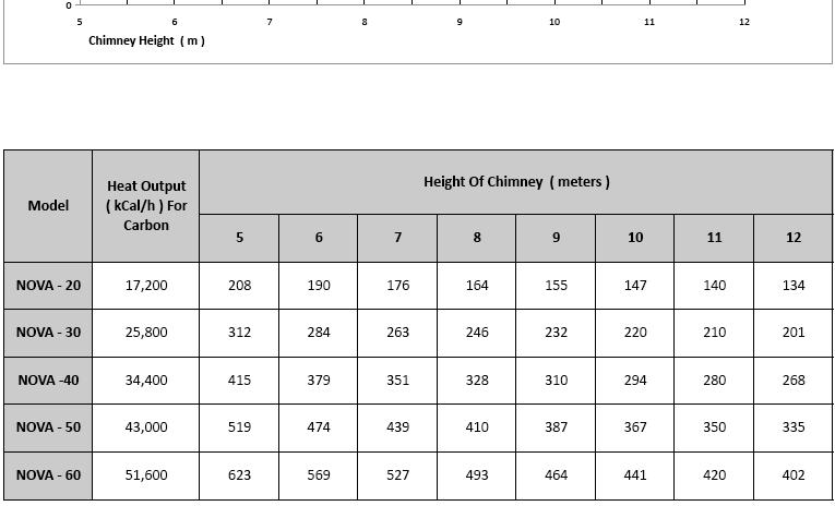
17 The effective chimney flue height is measured from the point of entry of the flue pipe into the chimney. Ensure that the calculation of the flue gas path and the connection of the flue gas system are only carried out by qualified personnel. If a wrong boiler chimney is connected, the warranty is not valid. Fig. 07 Chimneys and chimney connection warnings Flue pipe installation A sufficient flue draft of the flue gas system is the basic requirement for the correct functioning of the boiler. It fundamentally affects its performance and efficiency. Therefore, heed the following for the flue gas connection: Please note that the boiler must be connected to the flue gas system in accordance with the relevant local. Building code regulations, manufacture s instructions and in consultation with an approved flue installer. The boiler may only be connected to a flue gas system with proper flue draft (technical spec. table). The dimension calculations of the flue gas path must be based on the flue gas massflow rate at maximum rated output. 17 Fig. 08
18 Fig. 07 shows the proper flue gas connection with additional air equipment. Observe the following during the installation of the flue gas connection: Install a flue pipe connection with an inspection aperture for cleaning. Fasten the flue gas connector piece to the boiler. Feed the connector into the flue gas system on a short, ascending path. Avoid deflections, especially those with an angle of 90. Fasten and support connectors sufficiently. Since the flue pipe is only fixed into the flue gas system and push-fitted onto the boiler flue socket, it should be fitted very carefully so that it does not come loose. Only use parts of non-flammable materials for the flue gas system. The figures in tab. are only guide figures. The draft depends on the diameter, height, roughness of the chimney wall, and the temperature difference between combustion products and the outside atmosphere. We recommend the use of a chimney liner. Have precise calculations carried out by a heating engineer or flue installer. Coefficient = 0,041 ( for wood ) Coefficient = 0,027 ( for carbon ) F a = Sections resulting (cm2) = Coefficient QN = Boiler heat output ( kcal/h ) H = Height of chimney ( meters ) Boiler Flue duct Minimum Output size height 20 kw 150 mm 8 m 180 mm 7 m 200 mm 6 m 230 mm 5 m 30 kw 150 mm 10 m 180 mm 8 m 200 mm 7 m 230 mm 6 m 40 kw 150 mm 11 m 180 mm 9 m 200 mm 8 m 230 mm 7 m 50 kw 180 mm 10 m 200 mm 9 m 230 mm 8 m 250 mm 7 m 60 kw 180 mm 11 m 200 mm 10 m 230 mm 9 m 250 mm 8 m Recommended minimum chimney flue heights Have precise calculations carried out by a heating engineer or flue installer. 18
19 19
20 Accumulator tank capacity NOTE: The heat can be supplied for example by an accumulator tank. The following applies as a reference for the minimum storage boiler content: : Accumulator tank capacity in L : Nominal heat output in kw : Burning period in h : Heating load of the premises in kw : Minimum heat output in kw Fig. 09 Heating boilers using several allowable fuels should have the tank size based on the fuel that requires the largest accumulator tank. The accumulator tank is not necessary when the required volume is less than 300 l. Transportation and storage The manufacturer handles the boiler that is on a palette and secured against shifting (with screws). The boiler may not be transported in a different position than on its base. At least regular storage conditions shall be ensured during boiler storage and transportation (non - aggressive environment, air humidity lower than 75 %, temperature range from 5 C to 55 C, low dustiness and preventing influence of biological factors). The force may not be applied on the boiler coverings and panel during storage and transportation. Fig
21 Warning! Risk of injury from carrying heavy loads! If a larger quantity of tar has accumulated on internal walls of the combustion chamber, it must be removed with a scraper or burnt with hard wood (or coke), running the boiler at maximum operating temperature. Boiler must not be carried or transported without using forklift, trans pallet or other wheeled carrying vehicles. Use personal protective equipment (e.g. helmet, safety shoes, protective gloves). Risk of system damage from impact shocks! Fragile components could be damaged. Protect boiler connections from dirt if the boiler is not to be installed immediately. Insufficient cleaning can cause damage to the boiler and the voiding of warranty claims. Risk of system damage due to insufficient maintenance and cleaning! Boiler cleaning When the boiler is used, soot and fine ash accumulates on the boiler walls, mainly on heat exchanger ribs and in the flue neck, which reduces heat transfer and the boiler output. The actual quantity of soot and fine ash will depend on the quality of the fuel used and on the boiler operating conditions. If the boiler is oversized or was for some reason run at low temperatures, more soot is generated. This may also result in inadequate chimney thrust. Flue gas cleaning The boiler must be cleaned regularly, at least once a week, is with a steel brush. Open the boiler-stoking door. After open the cleaning plate. All boiler walls inside the combustion chamber and combustion gases routes should be cleaned. Fig

22 Open the ash pan door. Remove the combustion residues from the ash pan with the ash shovel. Do not place hot ashes in plastic and waste containers. Head Loses Fig. 12 Ash pan cleaning The ashes must be removed from the combustion chamber/ash pan every 1 3 days. Fig
23 Hydraulic Connection Diagrams Fig Fig. 15

24 Boiler combustion system Air inlets If the air vent is closed completely, there is no complete combustion. Creosote accumulates on the heating surfaces, which requires more cleaning effort. 1. Primary air inlet 2. Secondary air inlet NOVA series solid fuel boiler is designed as a three pass. NOVA series boiler has a large combustion chamber. 24
25 NOVA boiler parts 25

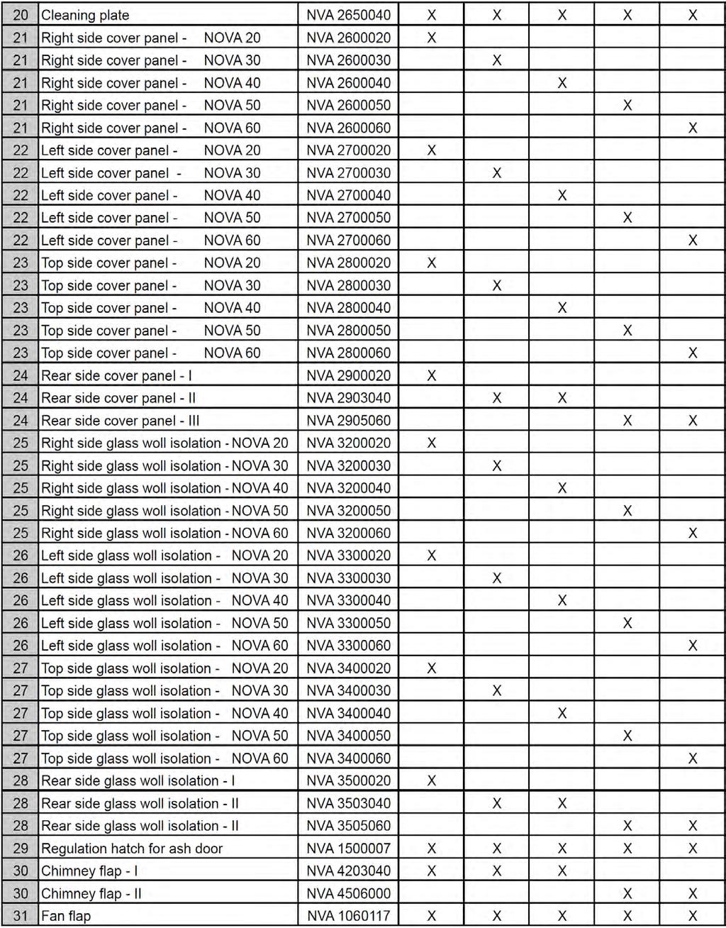
26 NOVA boiler spare parts lists 26
27 27
28 Troubleshooting 28
29 NOTES 29
30 NOTES 30
Index. Operating Instructions. Installation Instructions
 Index Information on the boiler plate Boiler dimensions, Boiler packaging dimensions Technical parameters Introduction Ensuring safety of equipment and people, Head loses 2 3 4 5 6 Operating Instructions
INSTALLATION AND OPERATING INSTRUCTIONS. Ariterm 60+
 INSTALLATION AND OPERATING INSTRUCTIONS Ariterm 60+ CONTENTS General.... 2 Installation.... 4-5 Installation of temperature limit valve... 6 Measurements and connections... 7 Technical specifications and
Installation & Manual. Model T-25
 Installation & Manual TR Central Heating Stove With Solid Fuel Model T-25 Tested according to DIN EN 13240 For product efficiency and emission values, see the declaration of conformity! TABLE OF CONTENTS
TABLE OF CONTENTS. Site preparation 2 Placement. 2 Chimney and stove pipe connections. 2
 TABLE OF CONTENTS SECTION TITLE PAGE 1. SITE PREPARATION AND INSTALLATION Site preparation 2 Placement. 2 Chimney and stove pipe connections. 2 Installation. 3 Water supply and return.. 3 Pressure/relief
SAUNA HEATER INSTALLATION AND OPERATING MANUAL
 SAUNA HEATER INSTALLATION AND OPERATING MANUAL Type Stoveman 13 Models 13R; 13R-M; 13; 13-M; 13R-LS; 13R-M-LS; 13-M-LS; 13-LS Heating output in the sauna room 15.4 kw Sauna room cubage 6-13 m³ Fuel Wood
Instructions for Operation and Maintenance of Containers
 Instructions for Operation and Maintenance of Containers Container Handling 1. Containers are designed for transport on a flat loading area that is 2.5 m wide, which enables support of the load-bearing
Heating, Air Conditioning, Ventilation. Отопление-Кондиционеры-Вентиляция. MTM 8-30 kw UNIVERSAL OIL HEATER OPERATING MANUAL
 Heating, Air Conditioning, Ventilation Отопление-Кондиционеры-Вентиляция MTM 8-30 kw UNIVERSAL OIL HEATER OPERATING MANUAL 1. Usage MTM 8-30 universal oil heater is designed for heating commercial rooms
INSTALLATION, OPERATION AND MAINTENANCE. Ariterm Vedo
 INSTALLATION, OPERATION AND MAINTENANCE Ariterm Vedo CONTENTS General...3 Installation...4-5 Laddomat 21 Connection diagram...6 Temperature control valve...7 About burning wood...8 Operation...9-11 Service
WHE 2.24 / WHE 2.24 FF
 EN Wall-hung gas boilers WHE 2.24 WHE 2.24 FF User Guide 300011777-001-C . Contents 1 Introduction.............................................................................3 1.1 Symbols used...........................................................................................3
USER S INFORMATION MANUAL
 USER S INFORMATION MANUAL UPFLOW & DOWNFLOW/HORIZONTAL CONDENSING GAS FURNACES SAFETY Recognize this symbol as an indication of Important Safety Information If not installed, operated and maintained in
ANLAGENBAU HEAT EXCHANGER w w w. a nla g enba u-b oehm er. d e Version 05/2015
 ANLAGENBAU HEAT EXCHANGER Table of Contents 1.0 General Information 1.2 User Instructions 1.3 Proper Use 1.4 General Safety Rules 2.0 Design and Function 3.0 Installation 3.1 Setting up the Plate Heat
Remeha. Fuel oil/gas boilers P 520. Installation and Service Manual A
 Remeha Fuel oil/gas boilers EN Installation and Service Manual 300016859-001-A 63115 Declaration of conformity The appliance complies with the standard model described in declaration of compliance. It
Figure 1 Solid fuel cook-stove KMŠ 70 and KVŠ 90H
 Figure 1 Solid fuel cook-stove KMŠ 70 and KVŠ 90H 1. 2. 3. 4. 5. 6. 7. Fire box door Ash pan door Air inlet control Fuel drawer Side flue gas connector Oven door with double glass Protective cover for
PER-EKO type KSW & KSW PLUS Instruction Manual
 TABLE OF CONTENTS INTRODUCTION..... 3 1. GENERAL INFORMATION..... 3 1.1. Application.. 3 1.2. Fuel..... 3 1.3. Dimensions & technical parameters........ 4 2. BOILER TECHNICAL SPECIFICATION...... 4 2.1.
INSTRUCTIONS FOR INSTALLATION AND MANUAL Solid fuel stove for central heating THERMO IN
 INSTRUCTIONS FOR INSTALLATION AND MANUAL Solid fuel stove for central heating THERMO IN To respected customer, We are very pleased for your trust and your decision to buy our product. You made a good choice,
Steam Trap BK 45 BK 45-U BK 45-LT BK 46
 Steam Trap BK 45 BK 45-U BK 45-LT BK 46 Original Installation Instructions 810437-08 Contents Foreword... 3 Availability... 3 Formatting features in the document... 3 Safety... 3 Use for the intended purpose...
HEAT RECOVERY AIR HANDLING UNIT
 HEAT RECOVERY AIR HANDLING UNIT OPERATION MANUAL KOMFORT_L v2(2)_en.indd 1 07.08.2015 15:0:44 CONTENTS Introduction General Safety regulations Transportation and storage regulations Manufacturer's warranty
User Manual GV25 GV35 GV702. Company information: Original instructions GV12066 (1)
") User Manual Original instructions GV25 GV35 GV702 Company information: www.vipercleaning.eu info-eu@vipercleaning.com GV12066 (1) 2012-04-10 USER MANUAL ENGLISH TABLE OF CONTENTS Introduction... 4 Manual
User Manual Original instructions GV25 GV35 GV702 Company information: www.vipercleaning.eu info-eu@vipercleaning.com GV12066 (1) 2012-04-10 USER MANUAL ENGLISH TABLE OF CONTENTS Introduction... 4 Manual
Varde Shape. Smoke Control Kit. Additional Installation and User Instructions for use in Smoke Control Areas
 Varde Shape Smoke Control Kit Additional Installation and User Instructions for use in Smoke Control Areas These instructions for fitting and operating the Smoke Control kit must be read in conjunction
Owner s Manual for. PennStoker
 Owner s Manual for PennStoker Table of Contents 1. Installation Placement ---------------------------------------------------------------------------------------- pg.3 Chimney Hook-up ---------------------------------------------------------------------------
USERS MANUAL FOR GAS BOILERS
 USERS MANUAL FOR GAS BOILERS PLEASE READ THE MANUAL CAREFULLY: IT CONTAINS IMPORTANT INFORMATION REGARDING SAFETY, INSTALLATION, USE AND MAINTENANCE OF THE APPLIANCE MODELS: NOVADENS 24 NOVADENS 24C NOVADENS
Wood-burning boiler CBB. User Guide E
 EN Wood-burning boiler User Guide 300008541-001-E . Contents 1 Symbols used...........................................................................3 2 Important recommendations...............................................................3
INSTRUCTIONS FOR INSTALLATION, SETTING AND USE
 BUILT-IN FIREPLACE INSTRUCTIONS FOR INSTALLATION, SETTING AND USE 1. BUILT-IN FIREPLACE SPECIFICATION - WIDE 730 mm - DEPTH 426 mm - HEIGHT 543 mm - NOMINAL POWER 11 KW - CHIMNEY POT DIAMETER Ø 180 mm
1. Contents Principle General information Parts list Assembly Technical drawing... 18
 1. Contents 1. Contents... 2. Principle... 2 3. General information... 3-7 4. Parts list... 8 5. Assembly... 9-17 6. Technical drawing... 18 2. Principle All instructions provided with products must be
T UNI 7000 F. Operating instructions For the user (2006/05) AU/GB
 AU/GB") 6 720 648 662-00.1T UNI 7000 F Operating instructions For the user AU/G 2 Contents Contents Contents 2 1 Safety information and explanation of symbols 3 1.1 For your safety 3 1.2 Explanation of symbols
6 720 648 662-00.1T UNI 7000 F Operating instructions For the user AU/G 2 Contents Contents Contents 2 1 Safety information and explanation of symbols 3 1.1 For your safety 3 1.2 Explanation of symbols
Maintenance 50 Serie CAUTION. Before resetting your electronic card that displays an error code. OVERHEAT MESSAGE
 29-10-2013 CAUTION Before resetting your electronic card that displays an error code. OVERHEAT MESSAGE Service the stove COMPLETELY as described in this manual. Check the chimney pipe. BLOCKED FLUE MESSAGE
Installation, operation and care Firewood boiler Vedolux 40 UB
 Installation, operation and care Firewood boiler Vedolux 40 UB 2008-09-23 Ver 2 Replaces: 05-11 VEDOLUX 40 UB Notes 0809 To be completed when the Vedolux 40 UB is installed Serial number:... Installation
/2010 US/CA
 6 720 646 148-11/2010 US/CA (en) For the user User s Instructions Condensing gas boiler Logamax plus GB162-L.B. 80 kw/100 kw Please read thoroughly before operating This manual is available in the English
Varde Aura. Smoke Control Kit. Additional Installation and User Instructions for use in Smoke Control Areas
 Varde Aura Smoke Control Kit Additional Installation and User Instructions for use in Smoke Control Areas These instructions for fitting and operating the Smoke Control kit must be read in conjunction
IDE 20 / IDE 30 / IDE 50 IDE 60 / IDE 80
 IDE 20 / IDE 30 / IDE 50 IDE 60 / IDE 80 EN OPERATING MANUAL OIL HEATER TRT-BA-IDE20-30-50-60-80-TC-001-EN Table of contents Information on the use of this manual... 1 Scope of delivery... 1 General safety...
1. SAFETY WARNINGS INSTALLTION Location Reversing the Door Swing Levelling the Unit... 3
 Contents 1. SAFETY WARNINGS... 1 2. INSTALLTION... 2 2.1 Location... 2 2.2 Reversing the Door Swing... 2 2.3 Levelling the Unit... 3 2.4 Cleaning Before Use... 3 2.5 Before Using Your Unit... CE BC108
REFRIGERATOR USER S MANUAL MODEL: HS-306LN
 REFRIGERATOR USER S MANUAL MODEL: HS-306LN Contents 1. SAFETY WARNINGS... 1 2. INSTALLTION... 2 2.1 Location... 2 2.2 Reversing the Door Swing... 2 2.3 Door Space Requirements... 6 2.4 Levelling the Unit...
Boiler. Fire tube Boiler:
 Boiler What is Boiler? A closed metallic vessel in which the water is heated beyond the boiling temperature by the application of heat by the combustion of fuels to convert it into steam. The function
OPERATION AND MONTAGE MANUAL ROOF FANS
 NO RFEC/U/2017-1 (EN) (valid since 18.08.2017) ROOF FANS RF/EC...-... / RFV/EC...-... Venture Industries Sp. z o.o. is not responsible for any damage caused by improper use of the fan and reserves the
Dovre 700CBW Cast Iron Wood Stove INSTALLATION INSTRUCTIONS 700G/1095
 Dovre 700CBW Cast Iron Wood Stove INSTALLATION INSTRUCTIONS 700G/1095 Before commencing with the installation it is important that these instructions are read and fully understood. The DOVRE 700CBW is
MANUAL FOR USE AND INSTALATION STOVE MODELS: D11-D17
 MANUAL FOR USE AND INSTALATION STOVE MODELS: D11-D17 CE Tested by the DIN EN 13240 15a B-VG Austria Type 1 Color Emajl d.o.o. Alaginci 87 a 34000 Požega Croatia www.color.hr team@color.hr 1 Attention!
USER S INFORMATION MANUAL
 USER S INFORMATION MANUAL UPFLOW/HORIZONTAL & DOWNFLOW TWO STAGE INDUCED DRAFT GAS FURNACES Recognize this symbol as an indication of Important Safety Information If the information in this manual is not
Protherm Tiger 24 (12) KTZ / 24 (12) KOZ
 KTZ / 24 (12) KOZ") Protherm Tiger 24 (12) KTZ / 24 (12) KOZ The boiler Serial No. is shown on the plate which is attached at the rear of the control panel. The control panel is accessible after removing the front cover.
Protherm Tiger 24 (12) KTZ / 24 (12) KOZ The boiler Serial No. is shown on the plate which is attached at the rear of the control panel. The control panel is accessible after removing the front cover.
Bergen PRPMXXXX. Smoke Control Kit Additional Installation and User Instructions for use in Smoke Control Areas
 Bergen Smoke Control Kit Additional Installation and User Instructions for use in Smoke Control Areas These instructions for fitting and operating the Smoke Control kit must be read in conjunction with
version 1.2 Made by NARVI Oy Finland Aito 16 / 20 / 24 / 16 VS / 20 VS / 24 VS Installation, user and maintenance instructions
 version 1.2 Made by NARVI Oy Finland Aito 16 / 20 / 24 / 16 VS / 20 VS / 24 VS Installation, user and maintenance instructions EN FI EN 2 Yrittäjäntie 14, FI-27230 Lappi tel. +358 0207 416 740 fax +358
OPERATION AND MONTAGE MANUAL ROOF FANS
 NO RF/U/2017 (ENGLISH) (valid since 13.10.2017) ROOF FANS RF / RFV Venture Industries Sp. z o.o. is not responsible for any damage caused by improper use of the fan and reserves the right to modify this
Operating and installation instructions for Fire Lotus H586
 Operating and installation instructions for Fire Lotus H586 Version 1, 24 May 2016 Introduction Congratulations on your new Lotus Fire. We hope and believe that it will give you many hours of warmth.
SCOTTY WOOD FURNACE Model DB-102 OWNER S MANUAL IMPORTANT
 SCOTTY WOOD FURNACE Model DB-102 OWNER S MANUAL IMPORTANT READ OWNER S MANUAL THOROUGHLY BEFORE INSTALLING FURNACE OR LIGHTING FIRE. CONSULT LOCAL AUTHORITIES IF IN DOUBT ABOUT YOUR LOCAL FIRE SAFETY REGULATIONS.
General safety precautions English
 English 1 1 1.1 About the documentation The original documentation is written in English. All other languages are translations. The precautions described in this document cover very important topics, follow
Installation and Operating Instructions for the following Woodsman models
 Issued: July 2009 Installation and Operating Instructions for the following Woodsman models These instructions should be read in conjunction with the flue installation instructions and drawings supplied
DH-Direct Fired Poultry Farm Diesel Heater
 DH-Direct Fired Poultry Farm Diesel Heater Comparison of Diesel Heater to Gas Heater Diesel LPG Gas LPG Gas KW 43 70 120 Fuel consumption/hr 3 5.1 8.8 Heat output 37000 60000 100000 Cost of fuel/lit or
TTV 1500 / TTV 3000 OPERATING MANUAL CONVEYING FAN TRT-BA-TTV TC EN
 TTV 1500 / TTV 3000 EN OPERATING MANUAL CONVEYING FAN TRT-BA-TTV1500-3000-TC2016-26-004-EN Table of contents Notes regarding the operating manual... 2 You can download the current version of the operating
Turbomat TM Operating Instructions. Froling GesmbH A-4710 Grieskirchen, Industriestraße 12
 Operating Instructions Turbomat TM 150-250 Translation of the original German operating instructions for the operator Read and follow the instructions and safety information! Technical changes, typographical
MTP (MTPAL) AIR HEATERS TECHNICAL DOCUMENTATION
 AIR HEATERS TECHNICAL DOCUMENTATION") Do Žlábku 733, 514 01 Jilemnice Subject: MTP (MTPAL) Technical Documentation Page 1 of 13 MTP (MTPAL) AIR HEATERS TECHNICAL DOCUMENTATION Table of Contents: Page: 2 Warranty Certificate 3 Quality and Completeness
Do Žlábku 733, 514 01 Jilemnice Subject: MTP (MTPAL) Technical Documentation Page 1 of 13 MTP (MTPAL) AIR HEATERS TECHNICAL DOCUMENTATION Table of Contents: Page: 2 Warranty Certificate 3 Quality and Completeness
Installation and Operation Manual IDRA PLUS DS. Solar Solar storage cylinder. Installation and Operation Manual
 Installation and Operation Manual IDRA PLUS DS Solar Solar storage cylinder EN Installation and Operation Manual GENERAL INFORMATION This - comprises pages. Rev. manual, Code ENGLISH General information
Rocket heater GAMERA
 Rocket heater GAMERA High efficiency heater on hard fuel Manufacturer: AGNON Ltd., Bulgaria Hissarya, 4 Han Kubrat STR. +359 885 525 464 WWW.GAMERA.EU ROCKETGAMERA@GMAIL.COM ATTENTION! Read the following
Installation, operation and care. Pellmax UB. Burner not included Replaces:
 Installation, operation and care Burner not included 2011-11-11 ver: Replaces: Contents 11.11 otes...3 General...4 Function...4 Technical data...5 System principle Pellmax with radiator and tank-in-tank
ST NF60188W ST NF60188STA
 ST NF60188W ST NF60188STA Contents Safety Warnings... 4 Unpacking... 6 Installation... 7 Location... 7 Levelling the Unit... 7 Free Space Requirements... 7 Reversing the Door Swing... 8 Cleaning Before
Operating Instructions
 Operating Instructions P4 Pellet 8-60 Read and follow the operating instructions and safety information. Subject to technical change. July 2009 Fröling Heizkessel- und Behälterbau Ges.m.b.H, Industriestrasse
TTV 4500 / TTV 4500 HP / TTV 7000
 TTV 4500 / TTV 4500 HP / TTV 7000 EN OPERATING MANUAL AXIAL FAN TRT-BA-TTV4500-4500HP-7000-TC-003-EN Table of contents The current version of the operating manual can be found at: Notes regarding the operating
USER'S MANUAL PGE Single Package Rooftop
 USER'S MANUAL PGE Single Package Rooftop Gas Heating/Electric Cooling Units Sizes 036-150 3 to 12-1/2 Tons NOTE TO INSTALLER: This manual should be left with the equipment owner. WARNING: If the information
User s Information Manual
 48AJ,AK,AW,AY020-060 Single-Package Rooftop Gas Heating Units with COMFORTLINK Controls and Scroll Compressors User s Information Manual NOTE TO INSTALLER This manual should be left with the equipment
MG SERIES - ENERGY CLASS A. Meeting the. MG series 1 / 7
 Meeting the MG series 1 / 7 Dear clients, Thank you for placing your confidence in our company and congratulations for your choice! You have purchased one of the many products of Gekas Metal company, intended
Fig. 1 - Unit PGD4, PGS4, WPG4
 OWNER S MANUAL 14 SEER Single -Package Air Conditioner and Gas Furnace System with R -410A Refrigerant Single Phase 2 to 5 Nominal Tons Three Phase 3 to 5 Nominal Tons PGD4andPGS4SeriesE,WPG4SeriesB Fig.
INSTRUCTIONS FOR USE OF COMBINED BOILER INTENDED FOR COMBUSTION OF BOTH PELLETS AND SOLID FUEL ABC COMBO
 INSTRUCTIONS FOR USE OF COMBINED BOILER INTENDED FOR COMBUSTION OF BOTH PELLETS AND SOLID FUEL ABC COMBO .Technical specifications Boiler power DESCRIPTION Water content in a boiler Required draft Supply
Test Unit GTL 100 for Fire Detectors
 Test Unit GTL 100 for Fire Detectors Description and Operation Manual Zertifiziertes QM System Nach DIN EN ISO 9001 Description and Operation Manual Table of Contents 1. Instructions 1.1 General 1.2 Standards
INSTALLATION, OPERATION AND MAINTENANCE. Ariterm Hybrid 20
 INSTALLATION, OPERATION AND MAINTENANCE Ariterm Hybrid 20 TABLE OF CONTENTS General...3 Installation... 4-5 Dimensions - with flue gas exhauster...6 Dimensions - without flue gas exhauster...7 Pipe installations...8
INSTRUCTION FOR THE USER THC V E OIL BLU
 INSTRUCTION FOR THE THC V E OIL BLU CONTENTS General safety information 4 Precautions 4 Control panel 5 Mode selection 8 User levels 10 Start-up 12 Temporary shutdown 15 Preparing for extended periods
Tips & Technology For Bosch business partners
 Tips & Technology For Bosch business partners Current topics for successful workshops No. 04 Trucks Filters for commercial vehicles Part 2 Rough conditions for truck filters Commercial vehicles are on
TIH 300 S / TIH 400 S / TIH 500 S / TIH 700 S / TIH 900 S / TIH 1100 S
 TIH 300 S / TIH 400 S / TIH 500 S / TIH 700 S / TIH 900 S / TIH 1100 S EN OPERATING MANUAL INFRARED HEATING PANEL TRT-BA-TIH300S-TIH400S-TIH500S-TIH700S-TIH900S-TIH1100S-TC-002-EN Table of contents Notes
OWNERS MANUAL MODEL DO110 & DO180 IS CERTIFIED TO: Unit Serial # Purchased From Company Address
 OWNERS MANUAL MODEL DO110 & DO180 IS CERTIFIED TO: UL 391 CAN/CSA B366.1 Unit Serial # Purchased From Company Address Name of Installer Installer Telephone # Date Installed IMPORTANT This manual must be
BUILT-IN GLASS HOB MODEL: EGH-G8592G(BK) EGH-G8593G(BK) Owner s Manual Please read this manual carefully before operating your set.
 EGH-G8593G(BK) Owner s Manual Please read this manual carefully before operating your set.") BUILT-IN GLASS HOB MODEL: EGH-G8592G(BK) EGH-G8593G(BK) Owner s Manual Please read this manual carefully before operating your set. Retain it for future reference. Record model number and serial number
BUILT-IN GLASS HOB MODEL: EGH-G8592G(BK) EGH-G8593G(BK) Owner s Manual Please read this manual carefully before operating your set. Retain it for future reference. Record model number and serial number
Turbomat TM Operating Instructions. Froling GesmbH A-4710 Grieskirchen, Industriestraße 12
 Operating Instructions Turbomat TM 150-250 Translation of the original German operating instructions for the operator Read and follow the instructions and safety information! Technical changes, typographical
INFRARED PARAFfIN / KEROSENE / model No: ir20.v2 1. SAFETY INSTRUCTIONS RECOMMENDED FUSE RATING: 5AMP
 InstructioNS for: INFRARED PARAFfIN / KEROSENE / diesel HEATER model No: ir20.v2 Thank you for purchasing a Sealey product. Manufactured to a high standard this product will, if used according to these
Operating Instructions
 Operating Instructions S3 Turbo Be sure to read and comply with the operating instructions and safety information Subject to technical change. Fröling Heizkessel- und Behälterbau Ges.m.b.H, Industriestrasse
ORIGINAL OPERATING INSTRUCTIONS ASH VACUUM CLEANER / 18L
 ORIGINAL OPERATING INSTRUCTIONS 02-11 ASH VACUUM CLEANER / 18L IMPORTANT! SAFETY INSTRUCTIONS When using the appliance, a few safety precautions must be observed to avoid injuries and damage. Please read
G-10s. Instruction Manual. G-Series Cooler UPRIGHT COOLER. Part No.11IPA
 G-Series Cooler UPRIGHT COOLER Part No.11IPA-062800 Instruction Manual FOR YOUR FUTURE REFERENCE Thank you for using our product. This manual will guide you in getting the best use of your cooler. Remember
Cooker Hood LA-72-CAN.
 Cooker Hood LA-72-CAN EN www.luxairhoods.com WARNINGS Safety This equipment can be used by children aged 8 or more, people with physical, mental and sensory disabilities or inexperienced users it they
model No: ir20.v2 FUSE
 InstructioNS for: model No: ir20.v2 INFRARED PARAFfIN / KEROSENE / diesel HEATER 70000Btu 230V Thank you for purchasing a Sealey product. Manufactured to a high standard this product will, if used according
Quadro 1, 2 & S-31A Insert
 Quadro 1, 2 & S-31A Insert Smoke Control Kit Additional Installation and User Instructions for use in Smoke Control Areas These instructions for fitting and operating the Smoke Control kit must be read
INDUCED DRAFT HIGHBOY AND COUNTERFLOW/HORIZONTAL GAS FURNACE
 INDUCED DRAFT HIGHBOY AND COUNTERFLOW/HORIZONTAL GAS FURNACE USERS INFORMATION MANUAL MODELS FOR USE WITH NATURAL GAS MHA-50N, MHA-75N, MHA-100N, MHA-125N, MDA-50N, MDA-75N, MDA-100N, MDA-125N FOR USE
Packaged Gas/Electric Units. Owner s Guide to Operating and Maintaining Your Gas/Electric Unit
 Packaged Gas/Electric Units Owner s Guide to Operating and Maintaining Your Gas/Electric Unit ELECTRICAL SHOCK HAZARD. FIRE OR EXPLOSION HAZARD Disconnect power at fuse box or service panel before performing
USER S INFORMATION MANUAL
 USER S INFORMATION MANUAL UPFLOW, DOWNFLOW, UPFLOW/HORIZONTAL & HORIZONTAL ONLY INDUCED DRAFT GAS FURNACES Recognize this symbol as an indication of Important Safety Information If the information in this
TECHNICAL AND OPERATIONAL DOCUMENTATION
 METAL AND BOILER FACTORY 28-100 Busko-Zdrój, Owczary, ul Przemysłowa 3 Tel No +4841 378 46 19, fax +4841 370 83 10 TECHNICAL AND OPERATIONAL DOCUMENTATION SAS MULTI FLAME BURNER ADAPTED FOR BURNING OF
INSTRUCTIONS MANUAL FOR USE AND MAINTENANCE
 INSTRUCTIONS MANUAL FOR USE AND MAINTENANCE Carbel models: C-60 Plus C-70 Plus C-80 Plus C-100 Plus C-70 Plus Double-sided C-80 Plus Double-sided C-100 Plus Double-sided CARBEL C/ Ciudad de Cartagena,
Refrigerator Freezer HD-368RWEW
 Refrigerator Freezer HD-368RWEW Contents 1. SAFETY WARNINGS... 1 2. INSTALLTION... 2 2.1 Location... 2 2.2 Reversing the Door Swing... 2-3 2.3 Door Space Requirements... 4 2.4 Levelling the Unit... 4 2.5
LISEO Insert. European Standard Certification UNE EN inserts. LISEO s.r.o. Folknářská 1246/21 Děčín 2 Nové Město
 LISEO Insert European Standard Certification UNE EN-13229 inserts LISEO s.r.o. Folknářská 1246/21 Děčín 2 Nové Město 405 02 INTRODUCTION.4 1. GUARANTEE CONDITIONS.4 1.1. SAFETY WARNINGS....4 1.2. GUARANTEE
TECHNICAL MANUAL. Multifuel Stove Model EW1MF. To be retained by the user for future reference. Serial Number. Document EW1MF 0209
 TECHNICAL MANUAL Multifuel Stove Model EW1MF To be retained by the user for future reference Serial Number. Document EW1MF 0209 Thank you for purchasing an ACR Heat Products stove. The Earlswood stove
Instruction Manual. Automatic fuel oil de-aerator SMART-FLO 3/K B100 COMPATIBLE
 Sid Harvey s 605 Locust Street Garden City, NY 11530 Instruction Manual Automatic fuel oil de-aerator SMART-FLO 3/K Read manual before use! Observe all safety information! Keep manual for future use! 05.2015
TTK 75 ECO OPERATING MANUAL DEHUMIDIFIER TRT-BA-TTK75ECO-TC-002-EN
 TTK 75 ECO EN OPERATING MANUAL DEHUMIDIFIER TRT-BA-TTK75ECO-TC-002-EN Table of contents Notes regarding the operating manual... 01 Information about the device... 02 Safety... 04 Transport...05 Start-up...05
!!! Sample Written Program For Your Company. For BOILER SAFETY. Provided By:!!!
 Sample Written Program For Your Company For BOILER SAFETY Provided By: P.O. Box 2136 Slidell, LA 70458 Phone: 985-781-1444 Fax: 985-781-1446 Email: info@se-safety.com Purpose Boiler Safety Program The
CALEFFI. Anti-condensation recirculation and distribution unit. 281 series 01224/14 GB. Replaces dp 01224/12 GB. Function
 Anti-condensation recirculation and distribution unit 8 series ACCREDITED ISO 900 FM 654 ISO 900 No. 000 CALEFFI 04/4 GB Replaces dp 04/ GB GB Function The anti-condensation recirculation and distribution
Owner s Information Manual
 48ES---A and 48VL---A Comfort and Performance 13 and 14 SEER Single Packaged Air Conditioner and Gas Furnace System With Puron (R---410A) Refrigerant Single and Three Phase 2---5 Nominal Tons (Sizes 24---60)
Contents Safety Warnings... 3 Unpacking... 5 Installation... 6 Product Overview Operation Cleaning Maintenance...
 L5017W/S/B Contents Safety Warnings... 3 Unpacking... 5 Installation... 6 Location...6 Levelling the Unit...6 Free Space Requirements...6 Reversing the Door Swing...7 Cleaning Before Use... 10 Before Using
Boiler Technical Specifications (2013)
") ACT Bioenergy Boiler Dimensions 0.5-0.85 Million Btu/h (150-250kW) Model CP500 CP600 CP750 CP850 Heat Output in MBtu/h (kw) 510 (150) 610 (180) 750 (220) 850 (250) Height ft (mm) 6 1 (1855) 6 1 (1855)
ACT Bioenergy Boiler Dimensions 0.5-0.85 Million Btu/h (150-250kW) Model CP500 CP600 CP750 CP850 Heat Output in MBtu/h (kw) 510 (150) 610 (180) 750 (220) 850 (250) Height ft (mm) 6 1 (1855) 6 1 (1855)
WARNING FIRE OR EXPLOSION HAZARD.
 2017 Lennox Industries Inc. Dallas, Texas, USA 506897-01 04/2017 Supersedes 10/2015 EL280DF SERIES GAS FURNACE Improper installation, adjustment, alteration, service or maintenance can cause property damage,
VENTING CLEARANCES. BBT NORTH AMERICA Bosch Group. Bosch Water Heating 340 Mad River Park, Waitsfield, VT TWH-V-26 page 1 of 6 rev 01/06
 page 1 of 6 VENTING CLEARANCES The vents should not be obstructed and all joints properly fitted. Floors, ceilings and walls must be cut or framed to provide necessary clearance to vents. Metal strippings
ELECTRIC FLAT PANEL FIREPLACE HEATER
 ELECTRIC FLAT PANEL FIREPLACE HEATER Model Numbers: 80-2000A-42 OWNER S MANUAL AC 120V 60Hz 1500W WARNING Read and understand this entire owner s manual, including all safety information, before plugging
Operating Instructions
 Operating Instructions Low Emissions and High Efficiency Condensing Oil Boiler DANGER! If these instructions are not followed exactly, a fire or explosion may be caused with serious property damage or
STEAM WALLPAPER STRIPPER MODEL HTW5
 STEAM WALLPAPER STRIPPER MODEL HTW5 From Serial Number 75154 (110 Volt North America only) OWNERS MANUAL & OPERATING INSTRUCTIONS 2016/11 Hiretech Part # 007717 WARNING For safe operation of this machine,
Bosch 80% AFUE Gas Furnace BGS80 Model
 Bosch 80% AFUE Gas Furnace BGS80 Model 4-Way Multipoise Category I Fan-Assisted Furnace User's Information Manual 3124627 2 Bosch 80% AFUE Gas Furnace User's Information Manual Data subject to change 06.2018
VETO CLEANER 500 FLUE GAS CLEANER
 As of serial number 3100 0001 VETO CLEANER 500 FLUE GAS CLEANER USER MANUAL SPARE PARTS LIST Manufacturer: ALA TALKKARI Veljekset Ala-Talkkari Oy FI-62130 HELLANMAA TEL. +358 6 433 6333 FAX +358 6 437
LISEO STOVES. European Standard Certification UNE EN stoves. LISEO s.r.o. Folknářská 1246/21 Děčín 2 Nové Město
 LISEO STOVES European Standard Certification UNE EN-13240 stoves LISEO s.r.o. Folknářská 1246/21 Děčín 2 Nové Město 405 02 INTRODUCTION.3 2 1. GUARANTEE CONDITIONS.3 1.1. SAFETY WARNINGS..3 1.2. GUARANTEE
VH60SS 60CM VISOR HOOD STAINLESS STEEL
 VH60SS 60CM VISOR HOOD STAINLESS STEEL INSTRUCTION MANUAL Thank you for purchasing our product. We hope you enjoy using the many features and benefits it provides. Before using this product please study
Glass Chimney Hood. Installation & User Instructions Please keep for future reference
 Glass Chimney Hood Installation & User Instructions Please keep for future reference 4897549 4897556 Important Please read these instructions fully before installing or using These instructions contain