Introduction. Disclaimer. Application. EasySplicer components
|
|
|
- Duane Sutton
- 6 years ago
- Views:
Transcription


1 USERS MANUAL 1
2 Table of contents Introduction... 3 Disclaimer... 3 Application... 3 EasySplicer components... 3 Basics... 4 Quick Start... 4 Turn on the EasySplicer... 4 Start with a Calibration... 4 Singlemode or Multimode... 4 Doing the Calibration... 5 Time to splice... 5 Oven operation sleeve protection... 6 Main Menu... 7 Setup Menu Preparing the fibers and place them in the Fusion splicer Don t forget the protective sleeve Stripping the fiber Cleaning the fiber Cleaving the fiber Place the cleaved and ready fibers in the splicer Splicing Cleaning the v-groove of the fusion splicer Cleaning the electrodes Oven maintenance Changing and adjusting the electrodes Error messages and how to resolve Technical specification
3 Introduction The EasySplicer incorporates all the best a Made in Sweden Fusion splicer can offer. NOTE: EasySplicer is a high precision instrument and should always be handled with care! Disclaimer SB Scandinavia AB reserves the right to modify the product in any way without prior customer notification or any other form of notice. In no event, shall SB Scandinavia AB be liable for any damages of any type, incidental, indirect, consequential or other, originating from or relating to this manual or the information contained herein. While SB Scandinavia AB tries to make the user manual complete and accurate, it may contain mistakes, and the user uses it solely at his or her own risk. Application Splicing and protection of most common types of SMF and MMF. EasySplicer components The following components are included and standard for splicing in the field: Item Description Quantity 1 EasySplicer 1 2 Power supply 1 3 Fiber cleaver 1 4 Fiber holders 250μm (black) 1 pair 5 Fiber holders 900μm (blue) 1 pair 6 Stripper 1 7 Carrying bag 1 3
4 Basics NOTE: The EasySplicer is a rugged field instrument designed to withstand field environment. However, to ensure best performance, it is important to keep maintenance as described later in this manual. Quick Start! Turn on the EasySplicer If available, connect the splicer to a power source. - The splicer will also start automatically if the power-supply is connected. Simply press any button to leave charging-mode. * Make sure that that unit is properly charged if operated by the internal battery-pack. Charge the unit at least 6-8 hours before using it the first time. - Turn on the EasySplicer by pressing down the ON -button (large button below the display). The splicer starts in ready-mode after a few seconds. * Before beginning to splice it is important to verify that the electrodes are in good (operational) condition. The electrodes are quite easily oxidized due to environmental conditions (like dirt in the air and/or moisture). The splicer has probably been stored for a while and lately in transport. Such oxide can be cleaned (burned off) by using the CLEAN ELECTRODES function (see also page 21). Start with a Calibration! Begin all work with a Calibrate. This is needed to adapt the splicer to its present environment (adapt to temperature, moisture etc.). Singlemode or Multimode? It s very important to setup the correct fiber-type in the splicer before doing the calibration. For ex. Select Singlemode fiber in the Menu if You are using a Singlemode fiber. - Press the Menu-button. Step with the down-arrow to SETUP and select it by pressing the large button (SELECT). - Step with the down-arrow to FIBER TYPE and select it. - Chose SINGLEMODE, MULTIMODE or OM1 fiber-type. Doing the Calibration! - Strip one fiber which You are about to splice (strip it some 5-6cm). 4
5 - Clean the fiber with alcohol, isopropyl or similar. Make sure not to touch the fiber with anything after cleaning as it will become dirty. Place the stripped and cleaned fiber across the V-grove (see picture below). You can see how the calibration should be done in our Video to be found at: Having placed the fiber in the V-grove enter the Menu again and step with down-arrow to CALIBRATE. Select it (large button) and the splicer will perform a calibration. This is seen on the display as the splicer will ignite the spark and shine through the fiber with various strength. The operation is finished after some 5 seconds and the display will show OK if the Calibration was done properly. If not, the display will show the text: CALIBRATE AGAIN. Time to splice! Place fiber in the fiber holders (250 fibers in the black holders and 900 fibers/pigtails in the blue holders). The fiber should stick-out some 3-4cm. - Don t forget to put on a shrink-tube (sleeve) over one of the fiber-ends before You start! 5

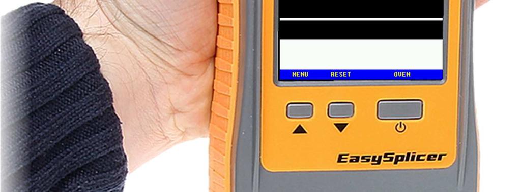
6 Strip and clean the fiber. Cleave the fiber. Place the fiber holders in the splicer. Push down the bracket which holds the fibers in place in the V-grove See the operation of the above at page and/or watch our Video at: If needed, press RESET. The fiber ends should be seen in the display, a bit like this when ready for splicing: Press the SPLICE -button (large button). The fibers will move together and spliced. The whole process will be shown in the display and take less than 10 sec. An automatic pull-test will be performed after the splicing. Finally, the splicer will show the estimated splice loss (in db and in green color) or, if the process failed, Bad splice (if so, re-do the operation from strip and cleave above). Oven operation sleeve protection! Open up the oven (with the little arm on the left hand side of the oven). Lift up the bracket over the V-grove and then open up both fiber-holders. Push the shrink-tube over the spliced part and place the fiber/tube in the center of the oven. Lock the fiber (and close the oven-lid) with the oven-arm. Start the oven by pressing the OVEN -button. The oven is preset for a 45sek operation but can be set in many combinations (see in the Menu-system). The splicer is ready for another splice while the oven is in operation (start from above again). Press RESET if the oven-operation is not needed. Main menu 6
7 Step up/down with the small buttons (UP/DOWN). Select Your choice with the SELECT-button. EXIT Exit from this Menu (back to Splice-mode). CLEAN ELECTRODES Run the CLEAN ELECTRODES -program to remove dirt/oxide on the electrodes. Running this program will ignite an extra powerful spark which will burn the electrodes clean. The CLEAN ELECTRODES will also be shown automatically in the display every 10 splices. Run the program several times (1-3 times) for best result. But not more than 5 times in a row. Then the splicer needs to cool for a couple of minutes. If 5 times is not enough the problem is elsewhere. CALIBRATE This function shall be used often for automatic environmental compensation. This should be done every time the environment changes, for ex. when starting a new workday, when coming back after lunch, when changing the type of fiber cable to use. Performing a Calibration: - Strip one fiber which You are about to splice (strip it some 5-6cm). - Clean the fiber with alcohol, isopropyl or similar. Make sure not to touch the fiber with anything after cleaning as it will become dirty. Place the stripped and cleaned fiber across the V-grove (see picture below). 7
8 You can see how it is performed in our VIDEO to be found at: Having placed the fiber in the V-grove enter the Menu again and step with down-arrow to CALIBRATE. Select it (large button) and the splicer will perform a calibration. If AUTO MODE is selected the calibration will start automatically when the lid is closed and the splicer sees the fiber going all the way. This is seen on the display as the splicer will ignite the spark and shine through the fiber with various strength. The operation is finished after some 10 seconds and the display will show OK if the Calibration was done properly. If not, the display will show the text: CALIBRATE AGAIN. * The splicer will adjust to the performed calibration with small steps at every splice but when changing environment this calibration will be needed (as the Calibration function compensate with many steps up/down if necessary). TURN OVEN ON Use this function to manually run the oven program. Normally, when a splice is done the oven program will be executed automatically (see above Oven operation page 6). But under some circumstances You might want to operate the oven manually. If so, place a fiber with a shrink-tube (sleeve) in the oven compartment and press the OVEN-button. The oven will start and run for as long as the oven time is set (factory preset is 45 sec.) Change time under SETUP and Oven below. 8
9 SETUP Takes You to the next sub-level where the following functions can be adjusted (see section below): * FIBERTYPE * SET CLOCK * OVEN * LANGUAGE * FIBER POSITION * ELECTRODES * DISPLAY * AUTO MODE * STARTUP CLEAN * SPLICE PAUSE * CALIB VISIBLE/CALIB NOT VISIBLE INFO Shows miscellaneous information of the splicer, like firmware version and number of total splices. LANGUAGE Set the language by stepping up/down with the small buttons. Press the large button (SELECT) for choosing a new language (or go to the top and select EXIT). SETUP MENU. EXIT Exit menu. FIBER TYPE Select the correct fiber-type You are about to splice: SINGLEMODE MULTIMODE OM1 9

10 SET CLOCK Set the internal clock by stepping up/down with the small buttons. Save value and move to the next line by pressing the large button (MOVE). Select EXIT for leaving this function. UP Changes selected items up one step. DOWN Changes selected items down one step. MOVE Steps to next item. OVEN Set the oven time by stepping up/down with the small buttons. Press the large button (SELECT) for choosing a new value (or go to the top and select EXIT). LANGUAGE Set the language by stepping up/down with the small buttons. Press the large button (SELECT) for choosing a new language (or go to the top and select EXIT). FIBER POSITION Calibrate fiber position when replacing cleaver (and/or if the fibers -for any reason- are not in the correct position when being placed in the V- grove). - Put fibers in their holders and place them in the splicer before starting. 10
11 Start automatic calibration of fiber zero point setting by pressing the large button (SELECT). If the fibers are visible and in the correct position like in the picture below then this new position shall be saved. Save by pressing the large button (SELECT). ELECTRODES ADJUST Automatic guide for adjustment of the electrodes. Please see: Changing and adjusting the electrodes below. ELEC. CHANGED Use this function to reset the splice-counter when the electrodes have been replaced. The electrodes are made to last some splices. 11
 in valid positions.")

12 DISPLAY ONLY IN ENGLISH VERSION!!! - This function, when enabled, will show all Menus with a larger font. AUTO MODE If selected, the splicer will automatically start a splice or a calibrate when the lid is closed if it detects fiber(s) in valid positions. STARTUP CLEAN If selected, the splicer will do a clean electrodes every time the splicer is turned on if the lid is closed and there are no fibers in the camera view. SPLICE PAUSE If selected, the splicer will pause and wait for a button to be pressed, when the fibers are in position for splicing. CALIB VISIBLE/CALIB NOT VISIBLE Select if the calibration process is to be displayed or if an hourglass is showed during calibration. 12

13 Preparing the fibers and place them in the Fusion splicer! Often, incorrect handling or preparation causes splice loss. It is crucial to keep tools and fiber clean; the invested time used in fiber and tool handling is more than compensated for in reduced troubleshooting effort. Don t forget the protective sleeve! Before preparing the fiber for splicing, make sure to put the protective sleeve in place. Place fiber in the fiber holders Place 250 fiber in the black holders,900 fiber/pigtail in the blue holders (and optionally 900 loose coat/loose tube in the red holders).the fiber should stick-out some 3-4cm (as seen in the pictures). 13

")

14 Stripping the fiber Hold the stripping tool to the edge of the fiber holder. Press the handles together and pull firmly away from the fiber holder to remove the coating (take away some 5-10cm). Cleaning the fiber Use a pair of tweezers equipped with cotton buds (or a similar tool) soaked with alcohol, isopropyl or similar. Press the tweezers together and clean the fiber with by moving the tweezers from the fiber holder towards the end of the fiber. Repeat, but rotate the tweezers. A squeaking sound indicates that the fiber is clean 14


15 Cleaving the fiber Lift the lid of the cleaver and position the fiber holder in the cleaver. Insert the fiber holder from above, a little from the right-hand side and let in slide back down into position (where the magnets will lock it). The fiber holder must be placed tightly towards its inner position, as far to the right as possible (check by pressing it gently). Magnets will move it in place. See picture below. Close the lid of the cleaver and push the sliding part away from you. 15

16 The fiber will be cut off (cleaved) and get a very straight 90 angle Lift the fiber holder in order to prevent the fiber from getting dirty. 16

. Don t try to push them in place from the outer position as it will be very hard to make the fiber fall in place into the V-grove.")
17 Place the cleaved and ready fibers in the splicer Open the main lid (on top) of the splicer and lift up the little bracket on top of the V-grove. Place the fiber holders in their wagons. - Keep the fiber holder at an angle and move it pass its intended resting place Lay the holder down and let it slide back into position (where the magnets will lock it). Don t try to push them in place from the outer position as it will be very hard to make the fiber fall in place into the V-grove. See picture below and our videos at: Close the bracket over the V-grove and lock the fibers in position 17
.")
18 Close the main lid. The fiber should now be visible in the monitor like this: Splicing Select the proper splice program in the menu (Singlemode- Multimode- or OM1- fiber). - Make sure a reset has been performed since last splice. - Make sure that the fibers/ V-grove are clean (if not, see page 13 and 20). GOOD VERY BAD 18
19 Are the fibers properly aligned (if not, see page 20 below)? BAD 19
20 If both fibers look good and clean, Press the SPLICE button and the automatic spliceprocedure will take place (moving the fibers together, igniting the spark, melting the glass together, make a pull test and estimate a loss value). If AUTO MODE is selected the splice will start automatically when the lid is closed and the splicer sees that the fibers are ready to splice. If estimated loss is larger than 0.1dB the splice is bad and has to be re-spliced. 20

21 Cleaning the v-groove of the fusion splicer The function of the high precision surface of the v-groove is very sensitive and must be kept 100% clean. It s quite easy to contaminate it with dirt so cleaning/maintenance should be done on a regular basis. Whenever there is a consistent problem with fiber offset (display showing OFFSET ERROR) then there is most certainly dirt in the V-grove which You must get rid off. To clean the v-groove proceed as follows: Put fibers in the fiber holders, strip clean and cleave them both. Put them into place in the splicer (like above, page 16) so You see both fiberends in the display. Gently slide the fiber holders back and forth in the V-grove quite many times. You can see how it s done at: The fiber ends are so sharp that they will cut the V-grove clean from any dirt which might have fallen into it. Most likely You will see some very small items (dirt) which will attach to the fiber during this procedure (see dirt on the fiber ends in the picture below). After finishing don t use these fiber ends for splicing (as they are worn down). - Strip, clean, cleave new fibers when ready. Apart from the method above You can also clean the V-grove with a cotton bud with alcohol/isopropyl. Preferably, the combination of both methods should be used. 21
.")

22 Cleaning the electrodes The electrodes of the splicer are sensitive and can get a bit oxidized due to moisture, dirt etc. in the air. Therefor we recommend that the user always clean the electrodes before starting a new work (before performing a Calibrate). The function is found in the Menu-system; CLEAN ELECTRODES, and it can be run some 2-4 times if the electrodes are very dirty. The EasySplicer will also, every 10 th splice, ask the user to clean the electrodes. This is suggested only as a precaution but running the CLEAN ELECTRODES function will keep the splicer fresh and free from problems. - Under some circumstances, it might be that the electrodes get so oxidized that the CLEAN ELECTRODES function won t be able to fully burn off the oxidation and the problems remain. If so, take for ex a sharp carpet knife or razor-blade and scratch gently on the surface of the electrodes (on the tips). See picture below and our video at: 22


23 Oven maintenance The oven needs to be cleaned and greased with regular intervals, to make removal of the shrink sleeves easy. Use silicon grease and apply it to the bottom of the oven with a cotton bud. See below. 23


24 Changing and adjusting the electrodes STEP 1. Upper electrode. Use a small flat screwdriver to lift the electrode lock (the circular brass part). While lifted use a pincer to carefully remove the old electrode. No strength is required, be careful. Keep the lock lifted with the screwdriver and insert the new electrode. 24

.")
25 Lower electrode. Loosen the two screws to loosen the electrode lock. Replace the electrode with a pincer. STEP 2. Adjust the position of both electrodes so that they are a just outside the camera view (not to be seen in the display). Enter the menu system and go to Setup and then to Electrodes. Select Adjust. 25

26 First thing to do is to place a fiber in the v-groove. This will guide the splicer to find the exact vertical center of the fiber. Then press NEXT. Adjust the upper electrode so that it is within the green area. When done, press NEXT and adjust the lower electrode within the green area. No strength is required, be careful. Carefully tighten the two screws to lock the electrode in position. CAUTION! DO NOT TIGHTEN TOO HARD. Just enough to lock the electrode in place. Done!!! 26
27 Error messages and how to resolve: Error message: Action: Resolve: Calibrate again. Calibration failed. Do a new calibration. CLEAN ELECTRODES Calibration failed 3 times. Clean the electrodes. First use the electronic clean in the menu (up to 4 times). And if that is not sufficient, also clean mechanically with a small knife. ERROR: CLOSE LID Lid is open. Close the lid. BATTERY EMPTY Battery empty. Connect the charger (and continue working/charging). BAD FIBER Cannot detect two good Fiber dirty, broken, faulty. looking fibers. TOO MUCH OFFSET V-grove IS dirty. Clean the v-grove. Offset over 10um V-grove is a bit dirty. Clean the v-grove. Angle=0.5 Angle=2.5 Cleaver didn't cut correctly. Too big angle made by a bad cleave. Simply strip and cleave again. CLEAN V-GROOVE V-grove IS dirty. Clean the v-grove. BAD SPLICE Auto estimation didn't The splice doesn't look good. approve the splice Redo the splice (or check with loss meter). Est. Loss: >0.1dB The splice failed. Do a calibrate on a new clean fiber and then redo the splice. RIGHT FIBER MISSING Right fiber is missing or Splicer cannot detect a good poorly placed. looking fiber on the right side. Re-do, re-place. LEFT FIBER MISSING Left fiber is missing or Splicer cannot detect a good poorly placed. looking fiber on the left side. Re-do, re-place. RIGHT FIBER DIRTY Right fiber is dirty. Strip, clean and cleave it again. LEFT FIBER DIRTY Left fiber is dirty. Strip, clean and cleave it again. Special operations with the buttons: If the splicer for some reason should stop responding to the buttons, there is a way to RESET the splicer (instead of removing the battery). Push both up and down buttons at the same time and a hardware reset will occur. If the middle button is pressed during power on, the splicer will prepare for receiving a new firmware. The white led will be on but the display will be black. This is described in more detail in the upgrade guide. This follows the new firmware. 27
28 Technical specification: Weight: Dimensions: Alignment: Fusion technique: Process: Typical Loss: Splice Programs: Fiber handling: Typical cycle time: Display: Magnification: Heat oven: Sleeve dimensions: Power source: Communication: Memory: 800g 230x98x53 mm Axial: Automatic Radial: Fixed v-groove Arc fusion Automatic SMF 0.03dB MMF 0.01dB 3 pre-defined: Singlemode Multimode OM1 Fiber holders, 2 pairs (250-BLACK and 900/pigtail-BLUE). (Optional 900-RED loose coat/loose tube). 7s + 35s (splice cycle + oven cycle). 2.8 Color TFT Camera 140x Built in. Max 60mm length, 2-5mm diameter. Battery: 7.4V/3400mAh. Li-Ion type. Built in. USB, mini USB-plug. Internal 1MB, External SD-card up to 32GB, FAT32 file system. Power supply: V AC / 6V DC / 1.5A Operating environment: Storage environment: Temperature 0 C to 45 C Humidity max 95% RH, non-condensing Temperature -20 C to 60 C Humidity max 98% RH, non-condensing 28
USERS MANUAL EasySplicer
 USERS MANUAL EasySplicer 1 Table of contents Introduction...3 Disclaimer...3 Application...3 EasySplicer components...3 Basics...4 Quick Start!...4 Turn On the EasySplicer...4 Start with a Calibration!...4
USERS MANUAL EasySplicer
 USERS MANUAL EasySplicer 1 Table of contents Introduction...3 Disclaimer...3 Application...3 Fusion splicer components...4 Basics...4 Order of operation...4 Connecting the splicer to power...4 Starting
User Guide. T-25S-L (Coating Clamp) T-25U-L (Coating Clamp)
 T-25U-L (Coating Clamp)") User Guide T-25S-L (Coating Clamp) T-25U-L (Coating Clamp) DESCRIPTION The T-25 is a fast compact fusion splicer, designed for joining optical fibres where the unit s small size and low weight are significant
User Guide T-25S-L (Coating Clamp) T-25U-L (Coating Clamp) DESCRIPTION The T-25 is a fast compact fusion splicer, designed for joining optical fibres where the unit s small size and low weight are significant
FTTHARCFUSIONSPLICER AD620
 FTTHARCFUSIONSPLICER AD620 Read this instruction manual carefully before operating the equipment. Adhere to all safety instructions and warnings contained in this manual. Keep this manual in a safe place.
Sumitomo T-39 Core Aligning Fusion Splicer
 Sumitomo T-39 Core Aligning Fusion Splicer De Winter Rudy RDeWinter@cnrood.com T-39 Single fibre core aligning splicer New from Sumitomo Electric Industries New features to increase productivity Light
Core Alignment All In One Fusion Splicer
 Economical Solution for Integrated Fiber Preparation Tool Demand. Core Alignment All In One Fusion Splicer Single Optical Fiber Fusion Splicer US Patent /9 2,09 The Revolution of a Splicer Integrated to
Fusion Splicing Recommendations for OFS Rollable Ribbon Using the Fitel S123 M12 Fusion Splicer
 Contents Fusion Splicing Recommendations for OFS Rollable Ribbon Using the Fitel S123 M12 Fusion Splicer Section General Fusion Splice Machine Settings 1 Fitel S123 M12 Fusion Splice Machines.. 2 Mass
OFS-950S/950R. Fusion Splicer. Operation Guide
 Fusion Splicer Operation Guide Contents 1. For Your Safety...5 2. Specifications and Components...8 2.1. Specifications...8 2.2. Components...8 3. Product Description...9 3.1. External Appearance...9 3.2.
Fujikura-70S Single Fibre Fusion Splicer
 Fujikura- Single Fibre Fusion Splicer Features Core-to Core alignment, Dual Axis observation system. World s quickest splicing 6sec. / tube-heating 9sec. Minimal manual operation. Splice in 4 steps. Multi-functional
View 3 User Manual. ARC Fusion Splicer. Please read this manual before operating your fusion splicer, and keep it for future reference.
 ARC Fusion Splicer View 3 User Manual Please read this manual before operating your fusion splicer, and keep it for future reference. 2014/10 Rev.0.2 View 3 User Manual 1 2 Contents 7 8 8 8 8 8 9 9 9 9
PRO-810. Fusion Splicer. Operation Guide
 Fusion Splicer Operation Guide Table of Contents 1. Warnings and Cautions for Operation...4 2. Description...6 2.1 Specification...6 2.2 Components...6 2.3 Description and Function of Splicer...7 2.3.1
User Manual SWIFT R5. Optical Fiber Arc Fusion Splicer. Read this service manual carefully. before running R5.
 User Manual Optical Fiber Arc Fusion Splicer SWIFT R5 Read this service manual carefully before running R5. Table of Contents I. For Your Safety 3 II. Specifications and Components 1. Specifications 2.
Optical Fiber Arc Fusion Splicer. Read this user manual carefully before running FX Fusion Splicer. FX Fusion Splicer USER MANUAL. PX EN, Rev.
 Optical Fiber Arc Fusion Splicer Read this user manual carefully before running FX Fusion Splicer FX Fusion Splicer USER MANUAL PX106545-EN, Rev.A This device complies with Part 15 of the FCC Rules. Operation
INSTRUCTION MANUAL 915FS. Optical Fiber Fusion Splicer. Register this product at
 INSTRUCTION MANUAL 915FS Optical Fiber Fusion Splicer Read and understand all of the instructions and safety information in this manual before operating or servicing this tool. Register this product at
User Manual SWIFT S5. Optical Fiber Arc Fusion Splicer. Read this service manual carefully. before running S5.
 User Manual Optical Fiber Arc Fusion Splicer SWIFT S5 Read this service manual carefully before running S5. Table of Contents I. For Your Safety II. Specifications and Components 1. Specifications 2. Components
Ribbon All In One Fusion Splicer
 Economical Solution for Integrated Fiber Preparation Tool Demand. Established 98 Advanced Test Equipment Rentals www.atecorp.com 800-404-ATEC (2832) Ribbon All In One Fusion Splicer US Patent /92,09 The
QUALITY CABLE & ELECTRONICS, INC.
 WWW.QUALITYCABLE.COM QUALITY CABLE & ELECTRONICS, INC. VFS-D7 Fusion Splicer URL:www.focusonchina.com Email: info@focusonchina.com All rights reserved! Contents 1. GENERAL INFORMATION...3 1.1 APPLICABLE
IFS-15H User Manual. ARC Fusion Splicer. Please read this manual before operating your fusion splicer, and keep it for future reference.
 ARC Fusion Splicer IFS-15H User Manual Please read this manual before operating your fusion splicer, and keep it for future reference. 2013/06 Rev.1.0 1 IFS-15H User Manual 1 2 Contents 7 8 8 8 8 9 9 9
OFS-920. Fusion Splicer. Operation Guide
 Fusion Splicer Operation Guide Contents I. Notes for Users...6 II. Product Specifications and Components...9 1. Product Specifications...9 2. Product Components... Error! Bookmark not defined. 3. Fiber
Instruction manual. FOFS Cougar. Optical fiber fusion splicer. Please read through this manual completely. before its first use.
 Instruction manual Optical fiber fusion splicer FOFS Cougar Please read through this manual completely before its first use. Contents I. Safety guide II. Product structure 1. Parts of the splicer 2. Requirements
SUPER COUGAR CORE ALIGNMENT FUSION SPLICER INSTRUCTION MANUAL
 SUPER COUGAR CORE ALIGNMENT FUSION SPLICER INSTRUCTION MANUAL Please read through this manual completely before its first use. 1.800.5000.FIS(347) fiberinstrumentsales.com @FiberExperts /FiberExperts fiberinstrumentsales.com
User Manual. Optical Fiber Fusion Splicer O F S 95 PLEASE READ THIS INSTRUCTION MANUAL CAREFULLY BEFORE OPERATING THE EQUIPMENT.
 User Manual Optical Fiber Fusion Splicer O F S 95 PLEASE READ THIS INSTRUCTION MANUAL CAREFULLY BEFORE OPERATING THE EQUIPMENT. ADHERE TO ALL SAFETY INSTRUCTIONS AND WARNINGS CONTAINED IN THIS MANUAL.
New Mass Fusion Splicer FSM-50R Series
 New Mass Fusion Splicer FSM-50R Series Hiroshi Sugawara, Kenji Takahashi, Kohji Ohzawa, Taku Ohtani, Manabu Tabata, Tomohiro Konuma and Toshihiro Tsuchida Fixed V-groove fusion splicers are commonly used
Ensuring Cabling Performance in the Customer-Owned Outside Plant. Keith Foord Product Manager Greenlee Communications
 Ensuring Cabling Performance in the Customer-Owned Outside Plant Keith Foord Product Manager Greenlee Communications Introduction: Outside plant fiber networks require low reflectance terminations for
Ensuring Cabling Performance in the Customer-Owned Outside Plant
 Ensuring Cabling Performance in the Customer-Owned Outside Plant Needs to be able to qualify the installation to validate bandwidth requirements are met Future high bandwidth applications Future Proof
The Optical Time Domain Reflectometry and the Fusion Splicer Laboratory exercise
 The Optical Time Domain Reflectometry and the Fusion Splicer Laboratory exercise 1 The purpose of the exercise...2 2 Background...2 2.1 Introduction to scattering and attenuation...2 2.2 Introduction to
FIBER FUSION SPLICER OPERATION MANUAL
 FIBER FUSION SPLICER OPERATION MANUAL 1 Contents 1. Notice before using... 1 1.1. Safety instruction... 1 1.2. Note... 2 1.3. Legal statement... 3 2. Start to comprehend splicer... 4 2.1. Overview of splicer...
LOUP II DRILL MONITOR OPERATION MANUAL. SOFTWARE v45
 LOUP II DRILL MONITOR OPERATION MANUAL SOFTWARE v45 Service and Technical Support Contact: Loup Electronics Inc. Address: 2960 N. 38th Street Lincoln, NE 68504 Phone: 877-489-LOUP(5687) 402-464-7131 Fax:
Qualified Partner Programme QPP. Field-termination of FO connectors Felice Guarna
 Qualified Partner Programme QPP Field-termination of FO connectors Felice Guarna Introduction Fiber to the Home, Fiber to the Office and Fiber to the Desk are not just slogans and are state of the art
Advanced Test Equipment Rentals ATEC (2832) Installation Note
 Installation Note") Established 1981 Advanced Test Equipment Rentals www.atecorp.com 800-404-ATEC (2832) Installation Note Agilent Technologies PSG Series Signal Generators E8241A, E8244A, E8251A, and E8254A Add Option 1E1
Established 1981 Advanced Test Equipment Rentals www.atecorp.com 800-404-ATEC (2832) Installation Note Agilent Technologies PSG Series Signal Generators E8241A, E8244A, E8251A, and E8254A Add Option 1E1
Reflectance, The Hidden Danger That Increases Bit Error Rates in Your Fiber Networks Denver, May 22nd, 2010
 Reflectance, The Hidden Danger That Increases Bit Error Rates in Your Fiber Networks Denver, May 22nd, 2010 Adrian Young Sr. Customer Support Engineer Foreword Reflectance is measured using an Optical
Setup Guide. Thank you very much for purchasing this product.
 Setup Guide Thank you very much for purchasing this product. To ensure correct and safe usage with a full understanding of this product's performance, please be sure to read through this manual completely
ASG EZ-9000GR Tape Dispenser User Manual ASG #66136
 ASG EZ-9000GR Tape Dispenser ASG #66136 Revision Date: 03/27/18 1 Read Before Use Warnings and Cautions The safety guidelines in this instruction manual must be observed in order to prevent injury to the
The EGT-1 is a single channel fully programmable digital EGT (Exhaust Gas Temperature) gauge.
 gauge.") EGT-1 EGT (Exhaust Gas Temperature) Gauge Operating Manual English 1.02 Introduction The EGT-1 is a single channel fully programmable digital EGT (Exhaust Gas Temperature) gauge. The EGT-1 s high accuracy
EGT-1 EGT (Exhaust Gas Temperature) Gauge Operating Manual English 1.02 Introduction The EGT-1 is a single channel fully programmable digital EGT (Exhaust Gas Temperature) gauge. The EGT-1 s high accuracy
USER MANUAL AND TECHNICAL MANUAL
 USER MANUAL AND TECHNICAL MANUAL Kanmed Universal Warming Cabinets Kanmed Blanket Warming Cabinets Kanmed Combination Cabinet GE-2300-070 / 4 2014-05-12 NOTE: This manual contains important information
30-YEAR LIMITED WARRANTY
 PROGRESS LIGHTING 30-YEAR LIMITED WARRANTY PROGRESS LIGHTING FAN MOTORS ARE WARRANTED TO THE END USER TO BE FREE OF ELECTRICAL AND/OR MECHANICAL DEFECTS FOR A PERIOD OF 30 (THIRTY) YEARS FROM DATE OF SALE.
Optical Fiber Arc Fusion Splicer. Read this user manual carefully before running K11. SWIFT K11 USER MANUAL
 Optical Fiber Arc Fusion Splicer Read this user manual carefully before running K11. SWIFT K11 USER MANUAL WWW.ILSINTECH.COM This device complies with Part 15 of the FCC Rules. Operation is subject to
Thermal Stripper, TSAB-40 User Manual
 Thermal Stripper, TSAB-40 User Manual User Manual Version 1.4 Table of Contents Introduction 4 Safety Considerations 5 Components 6 External Overview 7 Fiber Holder Platform Installation 8 Operation 12
INSTALLATION AND USER INSTRUCTIONS
 Separett FLAME INSTALLATION AND USER INSTRUCTIONS www.separett.com SEPARETT AB 2007 SEPARETT is a registered trademark for Separett AB Art. no. 11481-01 2 Thank you for choosing our incinerating toilet,
IntelliDoX Operator Manual
 IntelliDoX Operator Manual OPERATOR MANUAL TABLE OF CONTENTS Table of Contents Table of Contents...1 About this Publication...3 Important Safety Information: Read First...4 Getting Started...5 About the
OPERATING MANUAL Gfp 255C Please read this manual carefully before operating!
 OPERATING MANUAL Gfp 255C Please read this manual carefully before operating! Unpacking, assembly, and operating videos are available at www.gfpsmoothstart.com 1 Table of Contents Gfp 255C March 2015 Contents
OME Core Alignment Fusion Splicer Z1C. Guide to operation
 OME1324115-6 Core Alignment Fusion Splicer Z1C Guide to operation This product has been designed and manufactured to assure personal safety. Improper use can result in fire, electric shock or injury to
Proweld Equipment Owner & Maintenance Manual Maxiplast (Widos Shop 6)
") Proweld Equipment Owner & Maintenance Manual Maxiplast (Widos Shop 6) Tel: (781) 321-5409 - Fax (781) 321-4421 - Toll Free: (800) 343-3618 www.asahi-america.com - asahi@asahi-america.com Direct Sales:
Proweld Equipment Owner & Maintenance Manual Maxiplast (Widos Shop 6) Tel: (781) 321-5409 - Fax (781) 321-4421 - Toll Free: (800) 343-3618 www.asahi-america.com - asahi@asahi-america.com Direct Sales:
Notes for Users. Quick Installation Guide 2. Unpacking
 Notes for Users This supplement includes corrections and additional information for the manuals provided with this machine. Quick Installation Guide 2. Unpacking 1. 1. 1 1 1 1 1 1 6 1 1 1 4 3 1 1 1 DSA188
Advancing Fiber Optic Connectivity
 Advancing Fiber Optic Connectivity Fusion Spice-On Connectors by Brad Everette, America Ilsintech, Dallas, TX and Seung-Min Lee, Ilsintech, Daejeon, South Korea Presentation Overview Advancements in Fiber
COOKBOOK for. > A reference guide for all GTX Series users >>> <<<
 COOKBOOK for >>> Mandatory Temperature & Humidity Requirements : Required to keep the warranty! Temperature & Humidity are recorded
Thermal Stripper, TSFB-125 User Manual
 Thermal Stripper, TSFB-125 User Manual User Manual Version 1.4 Table of Contents Introduction 4 Safety Considerations 5 Components 6 External Overview 7 Fiber Holder Platform Installation 8 Operation 12
MAYFIELD CEILING FAN LISTED E ITEM # MODEL #BTH44ABZC5C BTH44BNK5C Español p. 20 ATTACH YOUR RECEIPT HERE.
 Harbor Breeze is a registered trademark of LF, LLC. All Rights Reserved. ITEM #0331094 0331096 MAYFIELD CEILING FAN MODEL #BTH44ABZC5C BTH44BNK5C Español p. 20 ATTACH YOUR RECEIPT HERE Serial Number Purchase
Product waste disposal - Protection of the environment:
 Product waste disposal - Protection of the environment: In accordance with the provisions of the Waste Electrical and Electronic Equipment (WEEE - 2002/ 96/ EC) Directive, used electric and electronic
OWNER S MANUAL. FLAT PANEL FIREPLACE HEATER Model Number: Serena (EF202A) WARNING CAUTION
 WARNING CAUTION") FLAT PANEL FIREPLACE HEATER Model Number: Serena (EF202A) OWNER S MANUAL WARNING Read and understand this entire owner s manual, including all safety information, before plugging in or using this product.
FLAT PANEL FIREPLACE HEATER Model Number: Serena (EF202A) OWNER S MANUAL WARNING Read and understand this entire owner s manual, including all safety information, before plugging in or using this product.
HOBOT-198 Glass Cleaning Robot User s Manual
 HOBOT-198 Glass Cleaning Robot User s Manual Copyright Copyright 2016 by HOBOT Technology Inc. All rights reserved. No part of this publication may be reproduced, transmitted, transcribed, stored in a
SUTTON 52 CEILING FAN
 SUTTON 52 CEILING FAN MODELS #50188, 50189, 50190 Español p. 19 Questions, problems, missing parts? Before returning to your retailer, call our customer service department at 1-877-361-3883, Monday - Thursday,
Replacement Guide: TCRU/ORU Model Name: Pro C901S/Pro C901
 Replacement Guide: TCRU/ORU Model Name: Pro C90S/Pro C90 Read this manual carefully before using this machine and keep it handy for future reference. How to Read This Manual Introduction This manual contains
52 CEILING FAN READ AND SAVE THESE INSTRUCTIONS FAN RATING AC 120V.
 Irene 52 CEILING FAN READ AND SAVE THESE INSTRUCTIONS FAN RATING AC 120V. 60Hz TABLE OF CONTENTS Tools and Materials Required... 1 Package Contents... 1 Safety Rules... 2 Mounting Options... 3 Hanging
The FTA-02 Fiber Arranger
 The FTA-02 Fiber Arranger Guide To Operation Sumitomo Electric Lightwave Corp. 78 Alexander Drive Research Triangle Park, NC 27709 Telephone: (919) 541-8100 Toll Free: (800) 358-7378 www.sumitomoelectric.com
ELSTON 52 CEILING FAN
 ELSTON 52 CEILING FAN MODEL #10290 Español p. 21 Questions, problems, missing parts? Before returning to your retailer, call our customer service department at 1-877-361-3883, Monday - Thursday, 8 am -
Using the QRAE Plus personal multigas monitor
 Using the QRAE Plus personal multigas monitor Firmware v 1.10 QRAE Plus The Hazardous Environment Detection Company QRAE Plus features Turning on the QRAE Plus Recommended Daily Start-up Procedure User
CARMEL 48 CEILING FAN
 CARMEL 48 CEILING FAN MODELS #50196, 50197 Español p. 21 Questions, problems, missing parts? Before returning to your retailer, call our customer service department at 1-877-361-3883, Monday - Thursday,
FM740 INSTRUCTION MANUAL VACUUM CLEANER. Contents HOUSEHOLD USE ONLY
 INSTRUCTION MANUAL VACUUM CLEANER FM70 Contents IMPORTANT SAFETY INSTRUCTIONS NAMES OF EACH PART PREPARATIONS BEFORE USE USING THE VACUUM CLEANER USING THE ATTACHMENTS EMPTYING THE DUST COMPARTMENT CLEANING
DUVAL 52 CEILING FAN MODELS #50201, Español p. 19 LISTED FOR DAMP LOCATION
 DUVAL 52 CEILING FAN MODELS #50201, 50206 Español p. 19 LISTED FOR DAMP LOCATION Questions, problems, missing parts? Before returning to your retailer, call our customer service department at 1-877-361-3883,
Operations Manual TS400. Test Station for G450/G460 Gas Detector
 TS400 Test Station for G450/G460 Gas Detector Operations Manual 1194 Oak Valley Dr, Ste 20, Ann Arbor MI 48108 USA (800) 959-0329 (734) 769-0573 www.gfg-inc.com GfG Products for Increased Safety Congratulations
TS400. Operating Manual. Test Station for Microtector II Series (G450/G460)
") Operating Manual TS400 Test Station for Microtector II Series (G450/G460) GfG GESELLSCHAFT FÜR GERÄTEBAU MBH KLÖNNESTRASSE 99 44143 DORTMUND, Germany TEL. +49 / (0)2 31 / 5 64 00 0 FAX +49 / (0)2 31 /
Operating Manual TS400 Test Station for Microtector II Series (G450/G460) GfG GESELLSCHAFT FÜR GERÄTEBAU MBH KLÖNNESTRASSE 99 44143 DORTMUND, Germany TEL. +49 / (0)2 31 / 5 64 00 0 FAX +49 / (0)2 31 /
CT500 Electronic Thermostat
 CT500 Electronic Thermostat OWNER'S GUIDE MERCURY NOTICE If this control is replacing a control that contains mercury in a sealed tube, do not place your old control in the trash. Dispose of it properly.
What to Expect with Your Installation. Tools Needed. 30 inches PA G E. To register your fan, please visit: 11 PA G E
 Table of Contents Tools Needed Mounting Options 1.888.227.2178 Ceiling Bracket 30 inches To register your fan, please visit: www.casablancafanco.com/register Wiring 11 Troubleshooting??? 15 14 1 13 Operation,
Frost Checklist and Troubleshooting Guide for NDA1402 & NEA1402
 Frost Checklist and Troubleshooting Guide for NDA1402 & NEA1402 REFRIGERATOR BULLETIN R82-7A NOVEMBER 2007 USA SERVICE OFFICE Dometic Corporation 2320 Industrial Parkway Elkhart, IN 46516 574-294-2511
Warnings 2. Installation Instructions 3. Wiring Instructions 3. Mounting Instructions 4-5. Replacement Element Installation 5. Replacement Parts 5-6
 TABLE OF CONTENTS Warnings 2 Installation Instructions 3 Wiring Instructions 3 Mounting Instructions 4-5 Replacement Element Installation 5 Replacement Parts 5-6 Heater Coverage Areas 6 General Notes 6
MGC Dock User s Manual
 User s Manual Contents Warnings Statements/Avertisseement... 3 READ FIRST BEFORE OPERATION... 3 Description... 4 Basic Operation... 5 Clip Dock Components... 5 LEDs... 5 User Operation... 6 Turning the
This is to certify that the optical output of the: SENSORNET LR-DTS Temperature Sensing System: (Variants Mark 1, Mark 2a and Mark 2b)
") Optical Services Ltd. This is to certify that the optical output of the: SENSORNET LR-DTS Temperature Sensing System: (Variants Mark 1, Mark 2a and Mark 2b) Meets the requirements stated in IEC 60825-1:2001
Optical Services Ltd. This is to certify that the optical output of the: SENSORNET LR-DTS Temperature Sensing System: (Variants Mark 1, Mark 2a and Mark 2b) Meets the requirements stated in IEC 60825-1:2001
C-IV 60 CEILING FAN READ AND SAVE THESE INSTRUCTIONS. FAN RATING AC 120V. 60Hz
 C-IV 60 CEILING FAN READ AND SAVE THESE INSTRUCTIONS FAN RATING AC 120V. 60Hz Please do not use any electric or battery powered tools in the assembly and installation of this or any Matthews Fan Company
Installation and operation manual
 Installation and operation manual Drying cabinet FC 18 PODAB 2009 2 Contents Safety regulations 5 Specification 6 Dimensions 6 Technical information 6 Assembly instructions 7 Installation of the cabinet
Operating & Maintenance Manual. Alert-4 Ethernet LCD Master Alarm
 Operating & Maintenance Manual Alert-4 Ethernet LCD Master Alarm w w w. a m i c o. c o m Contents User Responsibility 4 Introduction 4 Features 5 Description of the Alarm 5 Shipment Details 5 The Alarm
Turin LED Ceiling Fan
 Turin LED Ceiling Fan model no. no. 052-6972-6 Instruction Manual Toll-free: -866-827-4985 IMPORTANT: Please read and understand this manual before any assembly. Before beginning assembly of product, make
Kingfisher KI-3800 Light Source. Inexpensive handheld source for testing and commissioning optical fibre networks. Compact and rugged,
 TEST EQUIPMENT POWER METERS, LIGHT SOURCES Kingfisher KI-9800 Light Source Kingfisher KI-3800 Light Source Inexpensive handheld source for testing and commissioning optical fibre networks. Compact and
Dacor Technical Service
 Attention: This manual is just a section from the complete Wall Oven Service Manual. If you find that you require the complete service manual, which includes exploded views and parts, use and care information
BQ-260/260L. Important Information BOOK BINDER
 BOOK BINDER BQ-260/260L Important Information - This manual is designed to help you to install, operate and maintain Perfect Binder BQ- 260/260L. Read, understand and keep this manual in a safe and convenient
ST. KITTS CEILING FAN
 ITEM #0845047 ST. KITTS CEILING FAN MODEL #40829 Questions, problems or missing parts? Before returning this item to your retailer, call our customer service department at 1-800-643-0067, Monday - Thursday,
ITEM # SAIL STREAM CEILING FAN MODEL #40048
 ITEM #0609448 SAIL STREAM CEILING FAN MODEL #40048 Harbor Breeze is a registered trademark of LF, LLC. All Rights Reserved. Español p. 19 ATTACH YOUR RECEIPT HERE Purchase Date Questions, problems, missing
SOLO OWNERS MANUAL, OPERATING INSTRUCTIONS & INSTALLATION INSTRUCTIONS
 SOLO OWNERS MANUAL, OPERATING INSTRUCTIONS & INSTALLATION INSTRUCTIONS READ MANUAL BEFORE OPERATING SYSTEM Read the owner s manual thoroughly before operating to ensure the most efficient use of the system.
CEILING FAN OWNER'S MANUAL
 Style that revolves around you. CEILING FAN OWNER'S MANUAL QUATRO 10/09 WARNING: Read and follow these instructions carefully and be mindful of all warnings shown throughout. GENERAL INSTALLATION & OPERATION
MGC Dock User s Manual
 Operator s Manual Contents Warnings Statements/Avertisseement... 3 READ FIRST BEFORE OPERATION... 3 Basic Operation... 4 Clip Dock Components... 4 LEDs... 4 Operation... 5 Turning the Clip Dock On and
Small Box for Cable Termination. 3.1 Preparation of box 3.3 Mounting of the box on the wall
 FIST-SB2-8 I N S T A L L A T I O N I N S T R U C T I O N Small Box for Cable Termination Contents 1 Introduction 1.1 Product description 2 General 2.1 Tools 2.2 Kit contents 3 Installation and pre-assembling
Element. Controller. Manual for use and maintenance. Element. Climate Controller. Ag/MIS/UMGB /17 Rev 1.0 P/N:
 Manual for use and maintenance Element Controller Element Climate Controller Ag/MIS/UMGB-2439-02/17 Rev 1.0 P/N: 110584 Element Manual for use and maintenance Original instructions This manual for use
TOUCHDOWN 48 CEILING FAN
 TOUCHDOWN 48 CEILING FAN MODEL #50205 Español p. 20 Questions, problems, missing parts? Before returning to your retailer, call our customer service department at 1-877-361-3883, Monday - Thursday, 8 am
TMC. Installation and Operation Manual TMC. Temperature and Pressure Monitoring for Heating and Cooling Applications. Temperature Monitoring Control
 Installation and Operation Manual Temperature and Pressure Monitoring for Heating and Cooling Applications Temperature Monitoring Control VALVE OPEN ALARM System= 128 o F Alarm At= 130 o F RESET /BACK
OPERATING MANUAL. for the modular heat presses. Secabo TC5 SMART and TC7 SMART
 OPERATING MANUAL for the modular heat presses Secabo TC5 SMART and TC7 SMART Congratulations on the purchase of your Secabo heat press! Please read this operating manual carefully to ensure a smooth production
User s Manual RA-3030SS RA-3036SS. NOTE: This unit was designed for indoor residential use and DUCTED operation only.
 www.windsterhood.com User s Manual UNDER CABINET SERIES RA-3030SS RA-3036SS NOTE: This unit was designed for indoor residential use and DUCTED operation only. DO NOT USE OVER A WOOD GRILL OR MOUNT OUTDOOR
Table of Contents What to Expect with Your Installation. Tools Needed. Motor Housing.
 Table of Contents Congratulations on purchasing your new Casablanca ceiling fan! It will provide comfort and performance in your home or office for many years. This installation and operation manual contains
STATIC ELIMINATOR I443A INSTRUCTION MANUAL
 STATIC ELIMINATOR I443A INSTRUCTION MANUAL Thank you for purchasing a Static Eliminator. It is designed to eliminate the static charge from a charged object. Please read this manual before operating the
Fiber Optics for Todays Industry Applications
 Hands-On Fiber Optics for Todays Industry Applications (A Non-Telephone Company Course) Course Description This Hands-On course is designed to provide technicians with a practical understanding and Hands-On
Table of Contents What to Expect with. Tools Needed. Mounting Options. Wiring. Downrod. Canopy.
 Table of Contents Congratulations on purchasing your new Hunter ceiling fan! It will provide comfort and performance in your home or office for many years. This installation and operation manual contains
Wilcom. Model FR2 Fiber Ranger Optical Fault Locator OPERATING INSTRUCTIONS
 Wilcom Model FR2 Fiber Ranger Optical Fault Locator OPERATING INSTRUCTIONS Model FR2 Operating Instructions 812-655-002 January, 2002 Copyright (c) 1999 Wilcom All Rights reserved Wilcom reserves the right
TILGHMAN CEILING FAN. LISTED For Damp Location E ITEM # MODEL #WCK52LMW5N WCK52NWZ5N. Español p. 20 ATTACH YOUR RECEIPT HERE
 ITEM #0294980 0294981 TILGHMAN CEILING FAN Harbor Breeze is a registered trademark of LF, LLC. All Rights Reserved. MODEL #WCK52LMW5N WCK52NWZ5N Español p. 20 ATTACH YOUR RECEIPT HERE Serial Number Purchase
ETO 2 - Controller for ice and snow melting
 ETO 2 - Controller for ice and snow melting Advantages Simple adjustment knob with two functions Illuminated display where you can easily see the temperature status and other values Controls both pumps
Ionizer (Static Remover) STABLO-EX Instruction Manual
 STABLO-EX Instruction Manual") 321-56879-21E Jan. 2009 For Electronic Balances Ionizer (Static Remover) STABLO-EX Instruction Manual Read the instruction manual thoroughly before you use the product. Retain this instruction manual for
321-56879-21E Jan. 2009 For Electronic Balances Ionizer (Static Remover) STABLO-EX Instruction Manual Read the instruction manual thoroughly before you use the product. Retain this instruction manual for
MIX Boiler & Font Range Service Manual
 MIX Boiler & Font Range Service Manual 1000870# 1000871# 1000875# 1000880# 1000887# 1000878 1000879 2300268 www.marcobeveragesystems.com Ireland Tel: +353 (1) 295 2674 UK Tel: +44 (0207) 2744577 Service
Fiber Optic and CAT 5, 6, 7 and 8 Installer Premise Cabling
 Hands-On Fiber Optic and CAT 5, 6, 7 and 8 Installer Premise Cabling Certification Course Description This Hands-On course is customized to give Technicians the confidence and skills to maintain Fiber
ITEM # HYDRA CEILING FAN MODEL #41371
 ITEM #0883783 HYDRA CEILING FAN MODEL #41371 Harbor Breeze is a registered trademark of LF, LLC. All Rights Reserved. Español p. 20 ATTACH YOUR RECEIPT HERE Purchase Date Questions, problems, missing parts?
SPRINGHILL 44 CEILING FAN
 SPRINGHILL 44 CEILING FAN MODELS #50184, 50185 Español p. 20 Questions, problems, missing parts? Before returning to your retailer, call our customer service department at 1-877-361-3883, Monday - Thursday,
RIO 54 CEILING FAN MODEL # Español p. 19
 RIO 54 CEILING FAN MODEL #50195 Español p. 19 Questions, problems, missing parts? Before returning to your retailer, call our customer service department at 1-877-361-3883, Monday - Thursday, 8 am - 6
3M Crimplok + Connector 8700-UPC & APC SM SC 900 µm
 3M Crimplok + Connector 8700-UPC & APC SM SC 900 µm Instructions February 2012 3 78-0013-1746-6-B Safety Precautions Protective Eyewear c CAUTION Safety glasses should be worn when handling chemicals and