BR342 Ducted Installation Instructions Australian Version Electronic Wall Control
|
|
|
- Cora Stevens
- 6 years ago
- Views:
Transcription

1 Australian Version Electronic Wall Control 1
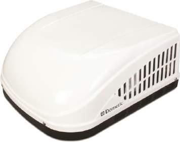
2 Introduction The BR342 reverse cycle rooftop air-conditioner is designed for installation onto Recreational Vehicles (RV s) at the time of manufacture or as a replacement for an existing ducted rooftop unit. Explanation of Symbols DANGER! Safety instruction: Failure to observe this instruction will cause fatal or serious injury. WARNING! Safety instruction: Failure to observe this instruction can cause fatal or serious injury. CAUTION! Safety instruction: Failure to observe this instruction can lead to injury. NOTICE! Failure to observe this instruction can material damage and impair the function of the product. NOTE Supplementary information for operating the product. 2
3 Safety Instructions Please observe the prescribed safety instructions and stipulations from the vehicle manufacturer and service workshops. The manufacturer accepts no liability for damage in the following cases: Faulty assembly or connection Damage to the product resulting from mechanical influences and excess voltage Alterations to the product without express permission from the manufacturer Use for purposes other than those described in the operating manual Note the following basic safety information when using electrical devices to protect against: Electric shock Fire hazards Injury 3
4 Safety Instructions Handling the Device WARNING! Installation and repair of the roof air conditioner may only be carried out by qualified personnel who are familiar with the risks involved and the relevant regulations. Inadequate repairs may cause serious hazards. For repair service, please contact the service centre in your country (addresses on the back page). Electrical devices are not toys. Keep electrical devices out of reach of children or infirm persons. Do not allow them to use electrical devices without supervision. Persons whose physical, sensory or mental capabilities or whose lack of experience and knowledge prevent them from using the device safely should not use it without supervision or instruction by a responsible person. Do not undo the upper cover of the roof air conditioner in the event of a fire. Use approved extinguishing agents instead. Do not use water to extinguish fires. CAUTION! The roof air conditioner must be installed securely so that it cannot fall down. Only operate the roof air conditioner if you are certain that the housing and the cables are not damaged. Do not use the roof air conditioner near flammable fluids or in closed rooms. Make sure no combustible objects are stored or installed near the air outlet. A distance of at least 50 cm must be kept. Do not reach into air outlets or insert any foreign objects in the device. 4
5 Safety Instructions Handling the Device 5 NOTICE! Only use the device as intended. The roof air conditioner is not suitable for use in agricultural or construction vehicles. Do not make any alterations or conversions to the device. Never drive through automatic car washes when the roof air conditioner is mounted. If faults occur in the refrigerant circuit, the system must be checked by a specialist company and repaired properly. The refrigerant must never be released into the air. Safety Instructions Handling Electrical Cables WARNING! The electrical power supply may only be connected by a qualified electrician CAUTION! Fit a fuse of at least 10 A to the connection with the vehicle s power supply. Attach and lay the cables so that they cannot be tripped over or damaged. NOTICE! Use cable ducts to lay cables through walls with sharp edges. Do not lay loose or bent cables next to electrically conductive materials (metal). Do not pull on the cables
 square opening (hereinafter referred to as \"roof opening\") is required for installing this unit Roof construction with rafters/joists support frames on a minimum of 405mm centres.")
6 Unit Data Roof Requirements A 350mm 350mm (±3.17mm) square opening (hereinafter referred to as "roof opening") is required for installing this unit Roof construction with rafters/joists support frames on a minimum of 405mm centres. Minimum of 38mm and maximum of 152mm distance between roof to ceiling of RV. Roof Cavity Depth Duct Cross-Sectional Area Duct Size Register Requirements Total System Static Pressure (Hi Fan, Grilles fitted) 50.8 to 139.7mm 13550mm² min Depth: mm Width: mm Total Length: m Short Run Length: 1/3 of Total No. per Run: 4 min Free Air Area: 9032mm² Duct End Distance: mm Elbow Distance: 381mm 1.8 to 3.0kPa Table A Air Distribution Duct Sizing & Design 6
; Amount of insulation in walls and roof; Geographical location where the")
7 Choosing a Fitment Location This unit is specifically designed for installation on the roof of an RV. When determining your cooling requirements, the following should be considered: Size of RV; Window area (increases heat gain); Amount of insulation in walls and roof; Geographical location where the RV will be used; Personal comfort level required. For one unit installation: The unit should be mounted slightly forward of centre (front to back) and centred from side to side. For two unit installations: Install one unit 1/3 and one unit 2/3 s from front of RV and centred from side to side. It is preferred that the unit be installed on a relatively flat and level roof section measured with the RV parked on a level surface. See table on right for maximum acceptable tilt. After Location Has Been Selected: Check for obstructions in the area where unit will be installed. See (FIG. 1). 7
8 Choosing a Fitment Location NOTICE! Maintain structural integrity. Otherwise damage to product and/or RV could occur. The roof must be designed to support 59 kg when the RV is in motion. Normally a 90.7kg. static load design will meet this requirement. Check inside the RV for return air grille (RAG) obstructions (i.e. door openings, room dividers, curtains, ceiling fixtures, etc.). See (FIG. 2). FIG. 2 19mm 431.8mm 431.8mm Roof Preparation 38mm WARNING! Fire or Electrical Shock Hazard: Make sure there are no obstacles (wires, pipes, etc.) inside RV s [roof / floor / walls]. Shut OFF gas supply, disconnect 240VAC power from RV, and disconnect positive(+) 12VDC terminal from supply battery BEFORE drilling or cutting into RV. Failure to obey these warnings could result in death or serious injury mm 31.75mm 44.45mm 38mm 431.8mm 8

9 Roof Preparation NOTE Opening Requirements: Before preparing the ceiling opening, the type of system options MUST be decided upon. Read all of the following instructions before beginning the installation. Carefully mark and cut the required roof opening. See Roof Requirements" section on pg 6. Using the roof opening as a guide, cut the matching hole in the ceiling. NOTICE! Maintain structural integrity. Otherwise damage to product and/or RV could occur. NEVER create a low spot on RV roof. Otherwise, water will pool and could cause a leak. The opening created must be framed to provide adequate support and prevent air from being drawn from the roof cavity. Framing stock 3/4 or more in thickness must be used. Remember to provide an entrance hole for power supplies, indoor temperature sensor (if applicable), thermostat communication cable, and furnace wires (if applicable) at the front of the opening. See (FIG. 3). 9
10 Air Distribution Duct Sizing & Design The installer of this system must design the air distribution system for their particular application. Several requirements must be met for the unit to operate properly. NOTICE! Make sure ductwork will NOT bend or collapse during and after installation, and that it is correctly insulated and sealed. Otherwise, damage to roof structure and ceiling could occur. All discharge air ducts must be properly insulated to prevent condensation from forming on their surfaces or adjacent surfaces during operation of unit. This insulation must be R-7 minimum. See (FIG. 4). FIG. 4 Ducts and their joints must be sealed to prevent condensation from forming on adjacent surfaces during operation of the unit. Return air openings must have 40 square inches minimum free area including the filter. Return air to the unit must be filtered to prevent dirt accumulation on unit cooling surface. 10
11 Air Distribution Duct Sizing & Design Dometic recommends the basic configuration shown in (FIG 6), for installing this system. We have found by testing, that this configuration works best in most applications. It is the responsibility of the installer to review each RV floor plan to determine the following: Duct size Duct layout Register size Register location Thermostat location Indoor Temperature Sensor Location FIG. 5 These items must be determined in conjunction with the Air Distribution Duct System Sizing & Design requirements. See "Table - Air Distribution Duct Sizing & Design" on page (4). 7742mm² free area per register 11
12 Air Distribution Duct Sizing & Design These items must be determined in conjunction with the Air Distribution Duct System Sizing & Design requirements. See "Table A - Air Distribution Duct Sizing & Design" on page 6. Wiring Requirements Route a copper, with ground, 240VAC supply wire from the time delay fuse or circuit breaker box to the roof opening. The proper size wire can be determined from chart on page 6. NOTE If vent fan was removed, the existing wire may be used provided it is of proper size, location, and correctly fused. This supply wire must be located in the front portion of the roof opening. The power MUST be on an appropriately sized separate time delay fuse or circuit breaker. The proper size protection can be determined from data table on page 6. Make sure that at least 381mm of supply wire extends into the roof opening. This insures an easy connection at the junction box. Protect the wire where it passed into the opening with approved method. 12
13 Placing Unit on Rooftop Remove the unit from the carton and discard carton. CAUTION! Lifting Hazard: Use proper lifting technique and control when lifting product. The rooftop unit weighs approximately 35 kg. Follow occupational health of safety guide when lifting or moving the unit. Failure to obey this caution could result in injury. Place unit on the roof. NOTICE! Do NOT slide unit. Otherwise, damage to gasket (on bottom of unit) may occur, and could cause a leak. Lift and place the unit over the prepared opening using the gasket on the unit as a guide. See (FIG. 4). Place the electronic wall control kit and the RAG kit inside the RV. These boxes contain mounting hardware for the unit and will be used inside the RV. FIG. 6 NOTE This completes the outside work. Minor adjustments can be done from inside the RV if required. 13
14 Installing the Unit Check gasket alignment of the unit over the roof opening and adjust if necessary. Unit may be moved from below by slightly lifting. See FIG. 7. Remove return air cover and ceiling template from carton. See FIG. 8. The unit is fixed using a four (4) bolt pattern for installing the RAG kit. These bolts and the electronic wall control are supplied separately. Reach up into the return air opening and pull the unit electric cord and control cables down for later connection. See FIG. 9. FIG. 7 FIG. 8 FIG. 9 14
15 Installing the Unit Hold the ceiling template up to the roof opening. Make sure the large plate faces the rear of the RV. See FIG. 10. Start each mounting bolt through the ceiling template and up into the unit base pan by hand. Install wood screw in each end of the ceiling template. This ensures a tight fit of the return air cover to ceiling. See FIG. 10. FIG. 10 NOTICE! Tighten mounting bolts to correct torque specifications. Overtightening could damage unit s base pan or ceiling template. Not enough torque will allow an inadequate roof seal, and could cause a leak. Tighten to 4.5 to 5.5Nm Tighten all four (4) mounting bolts EVENLY to 4.5 to 5.5 Nm. See FIG.10 FIG. 11 Measure the ceiling to roof thickness: If distance is mm, remove perforated tab from divider plate. See FIG. 11. If distance is mm, remove no tabs. Remove the backing paper from double-sided tape located on ceiling template. See FIG mm 15
16 Installing the Unit NOTICE! Incorrect installation of the divider could cause compressor to shortcycle, resulting in supply circuit overload and reduced product performance. FIG. 11 Place the divider plate up to bottom of the unit base pan firmly. The foam tape on the divider plate must seal to bottom of base pan. See FIG. 11. NOTE The adhesive on the double-sided tape is extremely sticky. Make sure the divider plate is properly positioned before pressing into place. FIG. 12 With slight pressure push the divider plate against the double-sided tape on the ceiling template. Locate the mm self-adhesive insulation supplied with the RAG kit. Remove the backing paper from the insulation and carefully stick onto the ceiling template divider plate. See FIG
17 Installing the Unit Excess width is intended to seal the divider plate to the sides of the roof opening. This is to help prevent cold air discharge from circulating into the unit return air opening. If the insulation is too high, stick excess height of the insulation to the unit base pan. Do not cover up unit rating plate. Wiring Connections Fix the return air sensor so it is position in the return air stream. Connect the communication wire to the wire from the electronic wall control (also refer to instructions provided with the wall control). Make connections for the 240VAC positive (+), negative (-) and earth from the supply to the rooftop unit and ensure they are well insulated. Tuck any excess wire up out of the way. WARNING! Electrical Shock Hazard: Verify 240VAC power is disconnected from the RV. Failure to obey this warning could result in death or serious injury. WARNING! Electrical Shock Hazard: Provide grounding in compliance with all applicable electrical codes. Failure to obey this warning could result in death or serious injury. 17
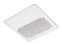
18 Installing the Return Air Cover Remove the return air grille from the return air cover. Place the return air cover up to the ceiling template. Install cover to template using six (6) supplied #8 x 3/8 blunt point Phillips head screws. Re-install filter return air grille into return air cover. Align tabs with mating notches and snap into place. Install two (2) hole plugs into screw holes in back of return air cover. See FIG. 13. FIG

19 Fitment of Optional Condensation Drain Extension The unit features condensation drain outlets which allow the fitment of a PVC tube in order to channel the condensation water to a specific area. For example it can be used to channel the condensation water to the rear of the caravan or RV and prevent runoff to the sides where doorways or windows are. FIG. 14 shows one example setup. Commonly available PVC tubing should be used of 12.7mm inner diameter and pushed onto the drain pipe fitting on the bottom of the rooftop unit around 15mm to help prevent detachment over time (refer to FIG. 14). The PVC tube should be routed around the foam support blocks on the underside of the rooftop unit to ensure the tube does not get compressed. The condition of the PVC tube should be regularly checked to ensure it is free of any defects that may prevent good drainage (such as being blocked, compressed or kinked). NOTICE! It is important to minimise sharp bends, kinks or high/low points in the tube as it may prevent proper draining of the condensation, and in severe cases this could result in water dripping inside the caravan. NOTE The PVC tube should NEVER raise higher than the level of the drain pipe fitting. FIG
20 Service Unit does not Operate If your unit fails to operate or operates improperly, check the following before calling your service centre. If RV connected to generator, check to be sure the generator is running and producing power. If RV connected to power supply by a land line, check to be sure line is sized properly to run unit load and it is plugged into power supply. Check your fuse or circuit breaker to see if it is open. Ensure fuse is not burnt, or circuit breaker is "ON" and not activated. After the above checks, call your local service centre for further help. This unit must be serviced by qualified service personnel only. When calling for service, always give the following: Unit model and serial number found on the identification label located on base pan of unit bottom. Return air grille must be removed from air distribution box to view. Air distribution box model and serial number found on rating plate located on ceiling template. Observe this rating plate through the filter opening. Contact Details 20
21 21 BR342 Ducted Installation Instructions Wiring Diagram Heat Pump BR36H70CR
INSTALLATION & OPERATING INSTRUCTIONS. Roof Top Unit. Model. USA SERVICE OFFICE Dometic Corporation 2320 Industrial Parkway Elkhart, IN 46516
 RECORD THIS INFORMATION FOR FUTURE REFERENCE: Model Number Serial Number ADB Model Number ADB Serial Number Date Purchased USA SERVICE OFFICE Dometic Corporation 2320 Industrial Parkway Elkhart, IN 46516
Air Conditioner
 RECORD THIS UNIT INFORMATION FOR FUTURE REFERENCE: Model Number Serial Number Date Purchased USA SERVICE OFFICE Dometic, LLC 2320 Industrial Parkway Elkhart, IN 46516 574-294-2511 Roof Top Unit Description
Roof Top Unit. Description Model Type Use With Air Distribution Box Model B CX51R B CX51R
 RECORD THIS UNIT INFORMATION FOR FUTURE REFERENCE: Type Number Product Number Serial Number ADB Number ADB Serial Number Date Purchased Roof Top Unit Description Model Type Use With Air Distribution Box
INSTALLATION INSTRUCTIONS FOR 6532 SERIES PACKAGE HEAT PUMP
 INSTALLATION INSTRUCTIONS FOR 6532 SERIES PACKAGE HEAT PUMP RV Products A Division of Airxcel, Inc. P.O. Box 4020 Wichita, KS 67204 1976-360 (1-02) PP TABLE OF CONTENTS 1. Warnings......................................................
INSTALLATION INSTRUCTIONS FOR 6636 SERIES PACKAGE AIR CONDITIONER
 INSTALLATION INSTRUCTIONS FOR 6636 SERIES PACKAGE AIR CONDITIONER TABLE OF CONTENTS 1. Warnings...................................................... 3 2. Component Match-Up...........................................
INSTALLATION INSTRUCTIONS FOR 6536 SERIES TWO TON PACKAGED HEAT PUMP
 INSTALLATION INSTRUCTIONS FOR 6536 SERIES TWO TON PACKAGED HEAT PUMP TABLE OF CONTENTS 1. Warnings...2 2. Component Match-Up...2 3. Unit Depiction Figures...3 4. Blower Performance Data...5 5. General
BRISK AIR 579 Series 590 Series 595 Series
 RECORD THIS UNIT INFORMATION FOR FUTURE REFERENCE: Model Number Serial Number Date Purchased USA SERVICE OFFICE The Dometic Corporation 220 Industrial Parkway Elkhart, IN 6515 (57) 29-2511 CANADA Dometic
INSTALLATION INSTRUCTIONS FOR MOUNTING KIT
 RV Products Division INSTALLATION INSTRUCTIONS FOR 8330-5501 MOUNTING KIT 8330-752 CONTROL BOX KIT (12 VDC COOL ONLY) 9330B755 CONTROL BOX KIT (12 VDC HEAT/COOL) 8530-750 CONTROL BOX KIT (24 VAC COOL ONLY)
INSTALLATION INSTRUCTIONS FOR SERIES TWO TON HIGH EFFICIENCY PACKAGED HEAT PUMP
 RV Products Division INSTALLATION INSTRUCTIONS FOR 46515 SERIES TWO TON HIGH EFFICIENCY PACKAGED HEAT PUMP TABLE OF CONTENTS 1. Warnings.................................................. 2 2. Component
MODELS , , Series
 RECORD THIS UNIT INFORMATION FOR FUTURE REFERENCE: Model Number Serial Number Date Purchased USA SERVICE OFFICE Dometic Corporation 509 South Poplar Street LaGrange, IN 46761 260-463-4858 CANADA Dometic
MODEL Roof-Top Heat Pump used with Air Distribution Box Kit
 R RECORD THIS INFORMATION FOR FUTURE REFERENCE BEFORE INSTALLING THE UNIT: Model Number Serial Number Date Purchased Place of Purchase USA SERVICE OFFICE The Dometic Corp. 509 So. Poplar St. LaGrange,
Rotary XL (558 Series) and Classic (548 Series)
 and Classic (548 Series)") INSTALLATION and OPERATING INSTRUCTIONS ROOF MOUNT AIR CONDITIONER Rotary XL (558 Series) and Classic (548 Series) QUICK START SHUR START MODELS MODELS 54812.041 54812.042 55812.041 55812.042 54815.041
INSTALLATION and OPERATING INSTRUCTIONS ROOF MOUNT AIR CONDITIONER Rotary XL (558 Series) and Classic (548 Series) QUICK START SHUR START MODELS MODELS 54812.041 54812.042 55812.041 55812.042 54815.041
INSTALLATION INSTRUCTIONS FOR. 230/240 VAC, 1ø, 50Hz SERIES RV ROOF TOP AIR CONDITIONER/HEAT PUMP
 RV Products Division INSTALLATION INSTRUCTIONS FOR 230/240 VAC, 1ø, 50Hz 47000 SERIES RV ROOF TOP AIR CONDITIONER/HEAT PUMP Airxcel, Inc. RV Products Division P.O. Box 4020 Wichita, KS 67204 Coleman is
INSTALLATION INSTRUCTIONS FOR 8330*5511 MOUNTING KIT
 RV Products Division INSTALLATION INSTRUCTIONS FOR 8330*5511 MOUNTING KIT 8330-752 CONTROL BOX KIT (12 VDC COOL ONLY) 9330A755 CONTROL BOX KIT (12 VDC HEAT/COOL) 8530-750 CONTROL BOX KIT (24 VAC COOL ONLY)
AIR CONDITIONER OWNER S MANUAL. Please read this manual carefully before operating your set and retain it for future reference.
 ENGLISH OWNER S MANUAL AIR CONDITIONER Please read this manual carefully before operating your set and retain it for future reference. Ceiling Suspended Original instruction ARNU18GV1A4 ARNU24GV1A4 ARNU36GV2A4
INSTALLATION INSTRUCTIONS FOR 6797A737 HEAT PUMP FLUSH MOUNT CEILING PLENUM
 INSTALLATION INSTRUCTIONS FOR 6797A737 HEAT PUMP FLUSH MOUNT CEILING PLENUM TABLE OF CONTENTS Warnings............................................................................... 2 Package Contents........................................................................
INSTALLATION INSTRUCTIONS FOR 7370A736 FLUSH MOUNT CEILING PLENUM
 INSTALLATION INSTRUCTIONS FOR 7370A736 FLUSH MOUNT CEILING PLENUM TABLE OF CONTENTS Warnings...2 Package Contents...2 General Information...3 Ceiling Plenum Installation Requirement...3 Supply Ducting
INSTALLATION MANUAL. Split-type Air Conditioner (Cooling and Heating) Outdoor Unit UQB09JJWC UQB12JJWC. Indoor Unit AQB09JJWC AQB12JJWC
 Outdoor Unit UQB09JJWC UQB12JJWC. Indoor Unit AQB09JJWC AQB12JJWC") AQB09JJ6WC_IM_E_2585 2006.4.17 4:26 PM Page 17 INSTALLATION MANUAL Indoor Unit AQB09JJWC AQB12JJWC Outdoor Unit UQB09JJWC UQB12JJWC ENGLISH FRANÇAIS ESPAÑOL Split-type Air Conditioner (Cooling and Heating)
AQB09JJ6WC_IM_E_2585 2006.4.17 4:26 PM Page 17 INSTALLATION MANUAL Indoor Unit AQB09JJWC AQB12JJWC Outdoor Unit UQB09JJWC UQB12JJWC ENGLISH FRANÇAIS ESPAÑOL Split-type Air Conditioner (Cooling and Heating)
Installation Manual. For Australian refrigerator models: N304M.3 (93 liter 3-way operation with LP gas, 240 volts AC, or 12 volts DC )
") Installation Manual For Australian refrigerator models: N304M.3 (93 liter 3-way operation with LP gas, 240 volts AC, or 12 volts DC ) N404M.3 (128 liter 3-way operation with LP gas, 240 volts AC, or 12
Installation Manual For Australian refrigerator models: N304M.3 (93 liter 3-way operation with LP gas, 240 volts AC, or 12 volts DC ) N404M.3 (128 liter 3-way operation with LP gas, 240 volts AC, or 12
RV Products Division INSTALLATION INSTRUCTIONS FOR SERIES PACKAGE AIR CONDITIONER
 RV Products Division INSTALLATION INSTRUCTIONS FOR 46413 SERIES PACKAGE AIR CONDITIONER 1. WARNINGS IMPORTANT NOTICE These instructions are for the use of qualified individuals specially trained and experienced
NOTE: All the illustrations in this manual are for explanation purposes only. Your air conditioner may be slightly different.
 RADS-51J RADS-61J Owner s Manual Room Air Conditioner with R-410A Heat Controller, Inc. 15 16 Contact an authorized service technician for repair or maintenance of this unit. Contact an authorized installer
INSTALLATION INSTRUCTIONS FOR 8330*633* COOL ONLY A/C 8330*635* HEAT READY A/C 8530*63** HEAT PUMP CHILLGRILLE FLUSH MOUNT CEILING ASSEMBLY
 RV Products Division INSTALLATION INSTRUCTIONS FOR 8330*633* COOL ONLY A/C 8330*635* HEAT READY A/C 8530*63** HEAT PUMP CHILLGRILLE FLUSH MOUNT CEILING ASSEMBLY DESIGNED AND MANUFACTURED BY THE MAKERS
Installation Instructions. For the 18 Built-In Dishwasher and Front Color Panels
 Installation Instructions For the 18 Built-In Dishwasher and Front Color Panels Printed in USA 154232102 Before You Begin DO NOT INSTALL DISHWASHER UNTIL YOU HAVE READ ALL INSTRUCTIONS. FOR YOUR SAFETY,
R32. Installation Manual Split Type Wall Mounted Air Conditioner. This appliance shall be installed in accordance with: REFRIGERANT
 SWING LRSWING Installation Manual Split Type Wall Mounted Air Conditioner COOL RUN C SPEED TURBO ON/OFF FAN COOL HEAT SWING SWING Rinnai Systems Models System Indoor Outdoor HSNRQ25B HINRQ25B HONRQ25B
INSTALLATION MANUAL. Split-type Air Conditioner (Cooling and Heating) Indoor Unit AQB18J6WC AQB24J2WC. Outdoor Unit UQB18J6WC UQB24J2WC
 Indoor Unit AQB18J6WC AQB24J2WC. Outdoor Unit UQB18J6WC UQB24J2WC") AQB8J6WC_IM_E_25864 2006.4.4 3:29 PM Page 7 INSTALLATION MANUAL Indoor Unit AQB8J6WC AQB24J2WC Outdoor Unit UQB8J6WC UQB24J2WC ENGLISH FRANÇAIS ESPAÑOL Split-type Air Conditioner (Cooling and Heating)
AQB8J6WC_IM_E_25864 2006.4.4 3:29 PM Page 7 INSTALLATION MANUAL Indoor Unit AQB8J6WC AQB24J2WC Outdoor Unit UQB8J6WC UQB24J2WC ENGLISH FRANÇAIS ESPAÑOL Split-type Air Conditioner (Cooling and Heating)
CONTENTS A FEW WORDS ABOUT YOUR NEW AIR CONDITIONING UNIT 2 ELECTRICAL DATA 2 OPERATING INSTRUCTIONS 4
 CONTENTS A FEW WORDS ABOUT YOUR NEW AIR CONDITIONING UNIT 2 ELECTRICAL DATA 2 OPERATING INSTRUCTIONS 4 CEILING UNIT DISPLAY 4 REMOTE CONTROL DESCRIPTIONS 5 COMPRESSOR DELAY FUNCTION 7 REMOTE CONTROL PREPARATION
RCM-77. Instruction Manual. G-Series Cooler. Manual is for the following model: RCM-77-N23EB. U.S. Patent No. 8,215,125 RECHARGEABLE COLD MERCHANDISER
 G-Series Cooler RCM-77 RECHARGEABLE COLD MERCHANDISER Manual is for the following model: RCM-77-N23EB U.S. Patent No. 8,215,125 Instruction Manual Manual is for the following model: RCM-77-N23EB Instruction
INSTALLATION INSTRUCTIONS FOR 8330*63**, 8530*63** CHILLGRILLE FLUSH MOUNT CEILING ASSEMBLY
 RV Products Division INSTALLATION INSTRUCTIONS FOR 8330*63**, 8530*63** CHILLGRILLE FLUSH MOUNT CEILING ASSEMBLY DESIGNED AND MANUFACTURED BY THE MAKERS OF COLEMAN -MACH AIR CONDITIONERS TABLE OF CONTENTS
installation and start-up instructions HUMIDIFIERS AND HUMIDISTAT
 installation and start-up instructions HUMIDIFIERS AND HUMIDISTAT HUM Cancels: II 912D-56-3 II HUM-56-1 7-98 MODEL HUMBBLFP1025-A-- FAN-POWERED HUMIDIFIER MODEL HUMBBLBP2018-A-- BYPASS HUMIDIFIER MODEL
INSTALLATION INSTRUCTIONS FOR 7330*5511 OR 7330*5512 MOUNTING KIT 7330B751 CONTROL BOX KIT (12 VDC COOL ONLY)
") INSTALLATION INSTRUCTIONS FOR 7330*5511 OR 7330*5512 MOUNTING KIT 7330B751 CONTROL BOX KIT (12 VDC COOL ONLY) 7530B750 CONTROL BOX KIT (24 VAC COOL ONLY) 8330A751 ZONE CONTROL KIT (12 VDC COOL ONLY) 8530B751
INSTALLATION INSTRUCTIONS FOR 7330*5511 OR 7330*5512 MOUNTING KIT 7330B751 CONTROL BOX KIT (12 VDC COOL ONLY) 7530B750 CONTROL BOX KIT (24 VAC COOL ONLY) 8330A751 ZONE CONTROL KIT (12 VDC COOL ONLY) 8530B751
INSTALLATION INSTRUCTIONS FOR MOUNTING KIT 7330B751 CONTROL BOX KIT (12 VDC COOL ONLY) CONTROL BOX KIT (12 VDC HEAT/COOL)
 CONTROL BOX KIT (12 VDC HEAT/COOL)") INSTALLATION INSTRUCTIONS FOR 8330-5511 MOUNTING KIT 7330B751 CONTROL BOX KIT (12 VDC COOL ONLY) 9330-755 CONTROL BOX KIT (12 VDC HEAT/COOL) 7530B750 CONTROL BOX KIT (24 VAC COOL ONLY) 9530-755 CONTROL
INSTALLATION INSTRUCTIONS FOR 8330-5511 MOUNTING KIT 7330B751 CONTROL BOX KIT (12 VDC COOL ONLY) 9330-755 CONTROL BOX KIT (12 VDC HEAT/COOL) 7530B750 CONTROL BOX KIT (24 VAC COOL ONLY) 9530-755 CONTROL
Installation Instructions
 HUMBBSFP1016 HUMCCSFP1016 Small Fan Powered Humidifier and Humidistat Installation Instructions! WARNING ELECTRICAL SHOCK HAZARD Failure to follow this warning could result in personal injury or death.
Installation Instructions
 Installation Instructions Before you begin... 2 Location... 2 Recommended grounding instructions... 2 Electrical requirements... 2 Exhaust requirements... 3 Water supply and drain requirements... 3 Please
EH0533 Indoor Climate Control
 EH0533 Indoor Climate Control 2.8 kw of cooling, 2.9 kw of heating Air Conditioning Efficient heating (air-source heat-pump) Cooling Remote control Suitable for low-wall installation No external unit required
INSTALLATION AND USER S MANUAL COOKER HOOD RS-600/A-S
 INSTALLATION AND USER S MANUAL COOKER HOOD RS-600/A-S RS-600 (CHS60SS)-GB-05.indd 1 6/8/2010 9:30:59 AM TABLE OF CONTENTS 1. Introduction 2 2. Safety precaution 2 3. Intended use 3 4. Parts supplied 3
Retrofit Instructions CLEARVIEW DAY COVER CAUTION: Please read this manual completely before attempting to install, operate or service this equipment
 Retrofit Instructions CLEARVIEW DAY COVER CAUTION: Please read this manual completely before attempting to install, operate or service this equipment This manual is Copyright 2019 Duke Manufacturing Co.
Installation and Operation Manual CLEARVIEW DAY COVER CAUTION: To view a video scan the QR code above
 Installation and Operation Manual CLEARVIEW DAY COVER To view a video scan the QR code above CAUTION: Please read this manual completely before attempting to install, operate or service this equipment
INSTALLATION INSTRUCTIONS FOR. 230/240 VAC, 1ø, 50Hz 473X3 SERIES RV ROOF TOP AIR CONDITIONER
 INSTALLATION INSTRUCTIONS FOR 230/240 VAC, 1ø, 50Hz 473X3 SERIES RV ROOF TOP AIR CONDITIONER Service Contact: Coast to Coast RV Services Pty Ltd. PO BOX 415 REGENTS PARK DC NSW 2143 Australia Tel: +61-2-9645
BlueHeat AirTop 2000 Heater
 BlueHeat AirTop 000 Heater Air Heater Installation Manual Ford E-Series 6.0L Diesel Beginning Model Year: 006 Special instructions for these models Part locations may differ slightly dependent on the vehicle
Instant Hot Water Dispenser Owner s Manual
 Model Hot1 Instant Hot Water Dispenser Owner s Manual Installation, Care & Use Instalacion, cuidado & uso Installation, soin et utilisation WHAT YOU SHOULD KNOW BEFORE YOU BEGIN For your satisfaction and
Installation Electric Dryers Instructions 01
 Installation Electric Dryers Instructions 01 Questions? Call 800.GE.CARES (800.432.2737) or visit our Web site at: GEAppliances.com This is the safety alert symbol. This symbol alerts you to potential
Installation Instructions
 Installation Instructions For the 18" Built-In Dishwasher Sears, Roebuck and Co. Sears Canada, Inc. Hoffman Estates, IL 60179 U.S.A. Toronto, Ontario, Canada M5B 2B8 154435201 Before You Begin DO NOT INSTALL
INSTALLATION INSTRUCTIONS FOR 9330F4552 FREE DELIVERY PLENUM KITS
 RV Products Division INSTALLATION INSTRUCTIONS FOR 9330F4552 FREE DELIVERY PLENUM KITS 8330-752 CONTROL BOX KIT (12 VDC COOL ONLY) 9330C755 CONTROL BOX KIT (12 VDC HEAT READY) 8530-750 CONTROL BOX KIT
EH0554 Indoor Climate Control
 EH0554 Indoor Climate Control 3.2kW heating or cooling capacity Air conditioning Dehumidification Cooling Efficient heating via air-source heat-pump Suitable for high- or low-wall installation No external
Single Zone LCD Thermostat Operating Instructions
 Fan *Heat Pump or Heat Strip F Single Zone LCD Thermostat Operating Instructions MODEL 3313192.XXX / 3313193.XXX //Heat Pump 3313194.XXX //Heat Strip TABLE OF CONTENTS About Your New Thermostat Features...3
 Installation Guide BI-98 Ice Maker www.u-lineservice.com Phone (414) 354-0300 FAX (414) 354-7905 Service & Parts Tech Lines Phone (800) 779-2547 FAX (414) 354-5696 OnlineService@U-Line.com 2005 U-Line
09/23/2013. RECORD THIS UNIT INFORMATION FOR FUTURE REFERENCE: Model Number: Serial Number: Date Purchased:
 AIR CDITIER & HEAT PUMP DIGITAL CTROL FOR DUCTED SYSTEM INSTALLATI AND OPERATING INSTRUCTIS FOR ACM135, ACM135SP,ACM150,ACM150SP,ACRG15,ACTH12 RECORD THIS UNIT INFORMATI FOR FUTURE REFERENCE: Model Number:
Multi-Function Cooktop
 INSTALLATION GUIDE Multi-Function Cooktop Contents Wolf Multi-Function Cooktop.................... 3 Multi-Function Cooktop Specifications............ 4 Multi-Function Cooktop Installation...............
Installation & Operating Guide
 HOT WATER DISPENSER Installation & Operating Guide Read all instructions thoroughly. Keep this guide for future reference. Proof of purchase is required for Warranty. Staple receipt or proof of purchase
TWLRZ-238 REFRIGERATOR
 TWLRZ-238 REFRIGERATOR May 2013 CONTENTS Parts and Features Instructions for Installation Cautions for Safety Operation Cleaning and Maintenance Changing the Light Bulb Reversing the Door 2 3 4 5 6 7 7
Questions? Call 800.GE.CARES ( ) or visit our Web site at: GEAppliances.com In Canada, call or visit
 or visit our Web site at: GEAppliances.com In Canada, call or visit") Installation Instructions Electric Dryer 01 Questions? Call 800.GE.CARES (800.432.2737) or visit our Web site at: GEAppliances.com In Canada, call 1.800.561.3344 or visit www.geappliances.ca BEFORE YOU
Installation Instructions Electric Dryer 01 Questions? Call 800.GE.CARES (800.432.2737) or visit our Web site at: GEAppliances.com In Canada, call 1.800.561.3344 or visit www.geappliances.ca BEFORE YOU
INSTRUCTION MANUAL. Model Number: DX K Wine Cooler BEFORE USE, PLEASE READ AND FOLLOW ALL SAFETY RULES AND OPERATING INSTRUCTIONS.
 INSTRUCTION MANUAL Model Number: DX-48.130K Wine Cooler CAUTION: BEFORE USE, PLEASE READ AND FOLLOW ALL SAFETY RULES AND OPERATING INSTRUCTIONS. TABLE OF CONTENTS 1. WINE COOLER SAFETY...114 2. IMPORTANT
Installation Instructions
 Installation Instructions For Fully Integrated NoFrost Combined Refrigerator-Freezers HC 2060/2061 HCB 2060/2061 7084 349-00 Important Please Read and Follow these Instructions These instructions contain
Questions? Call 800.GE.CARES ( ) or visit our Web site at: GEAppliances.com In Canada, call or visit
 or visit our Web site at: GEAppliances.com In Canada, call or visit") Installation Instructions Electric Dryer 01 Questions? Call 800.GE.CARES (800.432.2737) or visit our Web site at: GEAppliances.com In Canada, call 1.800.561.3344 or visit www.geappliances.ca BEFORE YOU
Installation Instructions Electric Dryer 01 Questions? Call 800.GE.CARES (800.432.2737) or visit our Web site at: GEAppliances.com In Canada, call 1.800.561.3344 or visit www.geappliances.ca BEFORE YOU
GENERAL INFORMATION CONTENTS
 AMTCM4H4R18 In line with the company s policy of continual product improvement, the aesthetic and dimensional characteristics, technical data and accessories of this appliance may be changed without notice.
GY11. Dachentlüfter mit Motor Montage- und Bedienungsanleitung. 6. Roof vent with motor Installation and Operating Manual.. 13
 DE Dachentlüfter mit Motor Montage- und Bedienungsanleitung. 6 Roof vent with motor Installation and Operating Manual.. 13 FR Ventilateur de toit à moteur Instructions de montage et de service..................
USER'S MANUAL PGE Single Package Rooftop
 USER'S MANUAL PGE Single Package Rooftop Gas Heating/Electric Cooling Units Sizes 036-150 3 to 12-1/2 Tons NOTE TO INSTALLER: This manual should be left with the equipment owner. WARNING: If the information
REG-183J REG-253J RADS-151J RADS-183J RADS-253J RAD-283J
 REG-183J REG-253J RADS-151J RADS-183J RADS-253J RAD-283J Owner s Manual Room Air Conditioner with R-410A Heat Controller, Inc. NOTE 1 Heat Controller, Inc. Room Air Conditioner with R-410A Owner s Manual
Installation Instructions Preference Wall Mount Range Hood
 Installation Instructions Preference Wall Mount Range Hood For use with models PHW30 and PHW36 Part No. 101745 Rev. D Table of Contents Important Safety Instructions... 1 Important Information About Safety
IMPORTANT SAFETY INFORMATION:
 08/53542/0 (AU/NZ) Issue 1 Owner s Manual Model BLF5051-AU/ PRISM 50" EN IMPORTANT SAFETY INFORMATION: Always read this manual first before attempting to install or use this fireplace. For your safety,
Installation Instructions Remote Blowers
 Installation Instructions Remote Blowers Models: REMP3, REMP16 Suitable for use in a household cooking area. Suitable for use with solid state controls. To complete this blower, a Dacor hood assembly or
Table of Contents. Specifications... page 2. Installation... page 3. Customizing... page 4. Reversing door swing... page 5
 Introduction The Scotsman Compact Refrigerator is a unique product, capable of being built into a cabinet because of its front vented, forced-air cooling system. It s also designed to be a companion to
INSTALLATION INSTRUCTIONS
 INSTALLATION INSTRUCTIONS C7BA Series Split System Indoor Cased Coils IMPORTANT ATTENTION INSTALLERS: It is your responsibility to know this product better than your customer. This includes being able
CEILING FAN OWNER'S MANUAL
 Style that revolves around you. CEILING FAN OWNER'S MANUAL VANTAGE with DC motor 12/14 WARNING: Read and follow these instructions carefully and be mindful of all warnings shown throughout. GENERAL INSTALLATION
2kW UPRIGHT FAN HEATER INSTRUCTIONS FOR USE
 2kW UPRIGHT FAN HEATER Model Number: IG9020 INSTRUCTIONS FOR USE Thank you for purchasing this product Please read these instructions 1 SAFETY INSTRUCTIONS Read and follow all of the instructions even
INSTANT HOT WATER DISPENSER
 INSTANT HOT WATER DISPENSER Tank Installation Materials required (not provided) 2 mounting bracket screws (and 2 plastic anchors if attaching to drywall) Shut-Off valve and T fitting Components When you
INSTALLATION INSTRUCTIONS FOR 7330C740 FLUSH MOUNT CEILING ASSEMBLY
 INSTALLATION INSTRUCTIONS FOR 7330C740 FLUSH MOUNT CEILING ASSEMBLY TABLE OF CONTENTS Warnings...3 Package Contents...3 General Information...3 Supply Ducting And Registers...3 Routing 115 VAC Wiring...5
WINDOW/WALL-TYPE ROOM AIR CONDITIONER
 Before using your air conditioner, please read this manual carefully and keep it for future reference. WINDOW/WALL-TYPE ROOM AIR CONDITIONER Prior to installation this air-conditioning unit must be submitted
DEHUMIDIFIER USER MANUAL 11 PINT FOR MODEL: 3PAD11 COMFORT...BUILT TO LAST
 COMFORT...BUILT TO LAST 11 PINT DEHUMIDIFIER USER MANUAL FOR MODEL: 3PAD11 Before using your dehumidifier, please read this manual carefully and keep it for future reference, along with your receipt. CONTENTS
MAYFIELD CEILING FAN LISTED E ITEM # MODEL #BTH44ABZC5C BTH44BNK5C Español p. 20 ATTACH YOUR RECEIPT HERE.
 Harbor Breeze is a registered trademark of LF, LLC. All Rights Reserved. ITEM #0331094 0331096 MAYFIELD CEILING FAN MODEL #BTH44ABZC5C BTH44BNK5C Español p. 20 ATTACH YOUR RECEIPT HERE Serial Number Purchase
CEILING FAN OWNER'S MANUAL
 Style that revolves around you. CEILING FAN OWNER'S MANUAL Vail with DC motor 10/15 WARNING: Read and follow these instructions carefully and be mindful of all warnings shown throughout. GENERAL INSTALLATION
WINDOW-TYPE AIR CONDITIONER
 Keep Well This Manual. Read Rules for Safe Operation and Instructions Carefully. WINDOW-TYPE AIR CONDITIONER 2200019260 11o3 1. ELECTRICAL SAFETY RULES... 1 2. UNIT PARTS IDENTIFICATION... 2 3. POINTS
OPERATION AND MAINTENANCE INSTRUCTIONS FOR ROOF TOP HEAT PUMPS AND CEILING PLENUMS
 OPERATION AND MAINTENANCE INSTRUCTIONS FOR ROOF TOP HEAT PUMPS AND CEILING PLENUMS RV Products A Division of Airxcel, Inc. P.O. Box 4020 Wichita, KS 67204 1976H207 (10-06) PP TABLE OF CONTENTS I. General
INSTRUCTION MANUAL. UNDERCOUNTER WINE & BEVERAGE COOLER (32 bottles capacity) MODEL:WC-30U
 MODEL:WC-30U") INSTRUCTION MANUAL UNDERCOUNTER WINE & BEVERAGE COOLER (32 bottles capacity) MODEL:WC-30U To ensure proper use of this appliance and your safety, please read the following instructions completely before
INSTRUCTION MANUAL UNDERCOUNTER WINE & BEVERAGE COOLER (32 bottles capacity) MODEL:WC-30U To ensure proper use of this appliance and your safety, please read the following instructions completely before
Installation Instructions
 Installation Instructions Over the Range Microwave Oven PVM88 Questions? Call -800-56-44 or Visit our Website at: GEAppliances.ca BEFORE YOU BEGIN Read these instructions completely and carefully. IMPORTANT
Downdraft Ventilation
 INSTALLATION GUIDE Downdraft Ventilation Contents Wolf Downdraft Ventilation...................... 3 Installation Considerations...................... 4 Downdraft Specifications.......................
200W Frostwatch Radiant Heater Operation Manual
 LEVFW200 200W Frostwatch Radiant Heater Operation Manual REMOVE ALL PACKAGING MATERIALS FROM THIS PRODUCT BEFORE USING IT LEVFW200 200W Frostwatch Radiant Heater IMPORTANT: Read these instructions fully
Installation Instructions
 Installation Instructions Above the Cooktop Microwave Oven JVM60 and JVM65 Questions? Call -800-56- or Visit our Website at: GEAppliances.ca BEFORE YOU BEGIN Read these instructions completely and carefully.
Split Portable Air Conditioner
 SP-IOM-1 Please read and save this manual. Read carefully before attempting to assemble, install, operate or maintain the product described. Protect yourself and others by observing all safety information.
OPERATING INSTRUCTIONS
 COMFORT CONTROL CENTER 2 THERMOSTAT OPERATING INSTRUCTIONS PROGRAMMABLE THERMOSTAT MODEL 3314080.000 BLACK 3314080.015 WHITE USA SERVICE OFFICE Dometic Corporation 1120 North Main Street Elkhart, IN 46514
Unpacking and removing shipping bolts. Connecting the drain line Leveling the washer Connecting to the power supply
 11 INSTALLATION Installation Overview Choosing the proper location Unpacking and removing shipping bolts Connecting the water line Connecting the drain line Leveling the washer Connecting to the power
Horizontal/Side Discharge Condensing Units
 INSTALLATION, OPERATION & MAINTENANCE MANUAL Horizontal/Side Discharge Condensing Units Models CMA12SD-0 CMA18SD-1 CMA24SD-1 CMA30SD-1 CMA36SD-1 CMA48SD-1 517.787.2100 www.marsdelivers.com Horizontal/Side
User s Manual RA-3030SS RA-3036SS. NOTE: This unit was designed for indoor residential use and DUCTED operation only.
 www.windsterhood.com User s Manual UNDER CABINET SERIES RA-3030SS RA-3036SS NOTE: This unit was designed for indoor residential use and DUCTED operation only. DO NOT USE OVER A WOOD GRILL OR MOUNT OUTDOOR
Installation & Operating Guide
 5-036 HOT WATER TANK Installation & Operating Guide Read all instructions thoroughly. Keep this guide for future reference. Proof of purchase is required for Warranty. Staple receipt or proof of purchase
Installation Instructions
 Installation Instructions For Fully Integrated NoFrost Combined Refrigerator-Freezers HC 2062 HCB 2062 HC/HCB 2062 7084 445-00 Important Please read and follow these instructions These instructions contain
INSTALLATION INSTRUCTIONS
 C7BA & C7BH Series Split System Indoor Cased Coils INSTALLATION INSTRUCTIONS IMPORTANT It is your responsibility to know this product better than your customer. This includes being able to install the
Contents. For your safety About your product Installing your appliance Using your appliance Care & cleaning...
 USER GUIDE TF5517S Contents For your safety..................................................... 1 About your product.................................................. 3 Installing your appliance...............................................
USER S MANUAL AND INSTALLATION INSTRUCTIONS IMPORTANT
 USER S MANUAL AND INSTALLATION INSTRUCTIONS P3BD Series 13 SEER Single Package Air Conditioner IMPORTANT Read this owner information to become familiar with the capabilities and use of your appliance.
DOUBLE DOOR COMPACT REFRIGERATOR. User Manual MODEL:KSTRC312BW KSTRC312BB
 DOUBLE DOOR COMPACT REFRIGERATOR User Manual MODEL:KSTRC312BW KSTRC312BB SERIAL/MODEL # S - IMPORTANT SAFETY INSTRUCTIONS Read and Save These Instructions This Owner s Guide provides specific operating
Instruction Manual. Window AC 12000BTU. Energy- Saving Mode. Wards.com MODEL: 12000BTU Item No.: V~, 60Hz, 1060W
 Energy- Saving Mode Window AC 12000BTU MODEL: 12000BTU 11.2 Montgomery Ward Customer Service 1112 7th Avenue, Monroe, WI 53566 8:00 am to Midnight, Monday through Friday Wards.com 1 888 557 3848 Instruction
For use with models: PGM304-1, versions M-B PGM365-1, versions M-E, M-F & M-G
 PGM-1 Cooktops For use with models: PGM304-1, versions M-B PGM365-1, versions M-E, M-F & M-G Install ation Instructions Part No. 65476 Rev. B Table of Contents Appliance Safety...1 Important Safety Instructions...2
UNIT MODEL/ POWER SUPPLY VOLTAGE VARIATION AMBIENT AIR ON CONDENSER
 Room Air Conditioner Installation and Operation Manual UNIT MODEL/ POWER SUPPLY VOLTAGE VARIATION AMBIENT AIR ON CONDENSER (VOLTS) MIN. MAX. MIN. F ( C) MAX. F ( C) WAC060K7A 127-1-60 114.3 139.7 70(20.1)
CEILING FAN OWNER'S MANUAL
 Style that revolves around you. CEILING FAN OWNER'S MANUAL Hover with DC motor 12/14 WARNING: Read and follow these instructions carefully and be mindful of all warnings shown throughout. GENERAL INSTALLATION
π H-6621 INDUSTRIAL DEHUMIDIFIER WARNINGS SPECIFICATIONS uline.com WATER REMOVAL ELECTRICAL REQUIREMENTS BUILT-IN ELECTRICAL SAFETY
 π H-6621 INDUSTRIAL DEHUMIDIFIER 1-800-295-5510 uline.com WARNINGS Plug into a grounded 3 prong outlet. Do not remove ground prong. Do not use an adapter. Do not use an extension cord if possible. Failure
QUICK CONNECT INSTALLATION MANUAL DUCTLESS MINI-SPLIT SYSTEM FOR MODELS: 2PAMSHQC12 2PAMSHQC18 2PAMSHQC24 2PAMSHQC36
 QUICK CONNECT DUCTLESS MINI-SPLIT SYSTEM INSTALLATION MANUAL FOR MODELS: 2PAMSHQC12 2PAMSHQC18 2PAMSHQC24 2PAMSHQC36 Before using your air conditioner, please read this manual carefully and keep it for
Installation Instructions
 Installation Instructions For Fully Integrated NoFrost Combined Refrigerator-Freezers HCB 1560/1561 7084 429-00 Important Please read and follow these instructions These instructions contain Danger, Warning
Installation & Service Manual. Models ALF 20, 30, 40, 50, 60, 80
 Installation & Service Manual Models ALF 20, 30, 40, 50, 60, 80 IMPORTANT! Read all safety instructions before installing, using, or servicing the heater. Installation & servicing should only be carried
RWC Issue: F. Description: ARISTON WALL CANOPY Model Numbers: ARCH90BIX. Model may vary slightly from images pictured. All measurements are in mm.
 RWC Issue: F Description: ARISTON WALL CANOPY Model Numbers: ARCH90BIX Model may vary slightly from images pictured. All measurements are in mm. 1 Overview Pre-installation Thank you for purchasing a quality
Viking Installation Guide
 Viking Installation Guide Viking Range, LLC 111 Front Street Greenwood, Mississippi 38930 USA (662) 455-1200 For product information, call 1-888-(845-4641) or visit the Viking Web site at vikingrange.com
INSTALLATION. Glass Panel Doors (select models) CAUTION
 CAUTION") Location Do not install refrigerator near oven, radiator or other heat source. If not possible, shield refrigerator with cabinet material. Do not install where temperature falls below 55 F (13 C) or rises
Location Do not install refrigerator near oven, radiator or other heat source. If not possible, shield refrigerator with cabinet material. Do not install where temperature falls below 55 F (13 C) or rises