Table of Contents (Hydronic)
|
|
|
- Charlene Simon
- 6 years ago
- Views:
Transcription

1
2 Table of Contents (Hydronic) About Us System Modeling Software Multi-Zoning and Energy Cost Features and Benefits Water Products Overview DX Products Overview Accessory Products Overview Equipment Sound Data MAC120 Air-Cooled Chiller Nomenclature Breakdown Guide Specifications Product Specifications Capacities Installation and Operating Manual Wiring Diagrams Certified Drawing MAC036,048 and 060 Air Cooled Chiller Nomenclature Breakdown Guide Specifications Product Specifications Capacities Circulating Pump Curve Installation and Operating Manual Wiring Diagrams Certified Drawing MHCCW (Ceiling Concealed) 2-pipe Chilled Water with Electric Heat. 1 to 3 Tons Nomenclature Breakdown Guide Specifications Product Specifications Chilled Water Capacities Hot Water Capacities Electric Heat Capacities CFM and Glycol Adjustments Capacity Adjustment Factors Installation and Operating Manual Wiring Diagrams Certified Drawing MHNCCW (Ceiling Concealed) 4-Pipe Chilled and Hot Water. 1 to 3 Tons Nomenclature Breakdown Guide Specifications Product Specifications Chilled Water Capacities Hot Water Capacities CFM and Glycol Adjustments Capacity Adjustment Factors Installation and Operating Manual Wiring Diagrams Certified Drawing Page
3 Table of Contents (Hydronic Continued) MCCW (Ceiling Concealed) 2-Pipe Chilled and Hot Water. 4 to 5 Tons Nomenclature Breakdown Guide Specifications Product Specifications Chilled Water Capacities Hot Water Capacities CFM and Glycol Adjustments Capacity Adjustment Factors Installation and Operating Manual Wiring Diagrams Certified Drawing MHWW (Hi-Wall) 2-Pipe Chilled and Hot Water. 1 to 3 Tons Nomenclature Breakdown Guide Specifications Product Specifications Chilled Water Capacities Hot Water Capacities Capacity and Glycol Adjustment Factors Installation and Operating Manual Wiring Diagrams Certified Drawing CFFWA (Universal Mount) 2-Pipe Chilled and Hot Water. 1 to 5 Tons Nomenclature Breakdown Guide Specifications Product Specifications Chilled Water Capacities Hot Water Capacities Capacity and Glycol Adjustment Factors Installation and Operating Manual Wiring Diagrams Certified Drawing CWA2 (Air Handler) 2-pipe Chilled Water with Electric Heat. 1.5 to 5 Tons Nomenclature Breakdown Guide Specifications Product Specifications Chilled Water Capacities Hot Water Capacities CFM and Glycol Adjustments Capacity Adjustment Factors Installation and Operating Manual Wiring Diagrams Certified Drawing CWA4 (Air Handler) 4-pipe Chilled and Hot Water 2 to 5 Tons Nomenclature Breakdown Guide Specifications Product Specifications Chilled Water Capacities Hot Water Capacities CFM and Glycol Adjustments Capacity Adjustment Factors Installation and Operating Manual Wiring Diagrams Certified Drawing Page
4 Table of Contents (Direct Expansion) MHCCX (Ceiling Concealed) DX with Electric Heat. 1 to 3 Tons Nomenclature Breakdown Guide Specifications Product Specifications Capacities CFM Adjustments Installation and Operating Manual Wiring Diagrams Certified Drawing MCCX (Ceiling Concealed) DX Only. 4 to 5 Tons Nomenclature Breakdown Guide Specifications Product Specifications Capacities CFM Adjustments Installation and Operating Manual Wiring Diagrams Certified Drawing MHNCCX (Ceiling Concealed) DX with Hot Water. 1 to 3 Tons Nomenclature Breakdown Guide Specifications Product Specifications DX Capacities CFM Adjustments Glycol Adjustments Capacity Adjustment Factors Hot Water Capacities Installation and Operating Manual Wiring Diagrams Certified Drawing MHWX (Hi-Wall) DX Only. 1 to 3 Tons Nomenclature Breakdown Guide Specifications Product Specifications Capacities Installation and Operating Manual Wiring Diagrams Certified Drawing FSFCA (Universal Mount) DX Only. 1 to 5 Tons Nomenclature Breakdown Guide Specifications Product Specifications Capacities Installation and Operating Manual Wiring Diagrams Certified Drawing Page
5 Table of Contents (Accessories) Accessories Storage Tanks Expansion Tank and Air Scoop Liquid Solution Bypass Valve Liquid Solution Control Valves Condensate Pump Control Thermostats Wye Strainer Circulating Pumps (1,1.5 & 2 HP) Circulating Pump Curve (1,1.5 & 2 HP) Circulating Pumps (.5 HP) Circulating Pump Curve (.5 HP) Ceiling Concealed Enclosures Sample Piping Banked Chiller Configuration Warranty Information Page


6 About Us Setting new industry standards is what we do best. At Multiaqua, our commitment to creating innovative air conditioning products has made us one of the most respected organizations in the industry. From concept to market, Multiaqua takes a hands-on approach to ensure that each and every step meets our stringent standards of quality, durability and dependability. All Multiaqua products are designed with the future in mind. That s why all air conditioning products are flexible, which makes it easy to adapt to virtually all kinds of building applications. Whether it s residential or commercial air conditioning needs, Multiaqua has the products to meet or exceed all expectations. Manufacturing Excellence Our beliefs in quality is more than just a practice, it is something we take great pride in. Our quality management system is integrated with international quality requirements of ISO That is why some of the biggest OEM names in the air conditioning industry use Multiaqua products in their units. In fact, Multiaqua chillers were part of air conditioning system that won first place awards in the Quality Home Comfort Awards Competition, which was created to honor the best in residential comfort system design and application. Our products are tested and certified to the UL, CE, ETL, UL1995 and ARI standards; the most respected and stringent in the world. Experience The Future At Multiaqua, we invite you to come experience the future of air conditioning and see why more and more companies are discovering the new standard of air conditioning excellence. And by combining cost effectiveness, innovation and quality, Multiaqua will continue to provide air conditioning products that will be the most sought after in the world. 1
7 Multiaqua Makes Hydronic System Design Easy NAME: MULTIAQUA LOCATION: SOUTH CAROLINA BTU/H 7.6 GPM BTU/H 5 GPM BTU/H 5 GPM BTU/H 4.9 GPM BTU/H 6.3 GPM BTU/H 7.6 GPM ICL-2 ICL-3 ICL-4 ICL-5 ICL-6 ICL-7 45 F 55 F 45 F 55 F 45 F 55 F 1" 45 F 1" 55.4 F 45 F 55 F 45 F 55 F BTU/H 12.6 GPM 55 F 145' 1" 1" 1" 145' 145' 1" 5' 5' 1" 5' 1" 1.5" 1' 5' 1.25" 5'1.25" 1.25" 5' 1' 1.5" 5' 1.25" ICL-1 45 F 100' 1.25" 1.25" 145' 1.25" 1.25" 1.25" 1.5" 145' 1.5" 55 F BTU/H 9.8 TONS 24.5 GPM (50%) 1.25" 100' 1.5" 1.5" 145' 2" 49 GPM 66.7 FT 2.5" 0' 10' 1" BYPASS VALVE 1' 2.5" 73.1 GAL STOR-1 ET GAL 2.5" 5' 5' 2" 5' 2.5" 5' 2" 0' 1' 2" 45 F 55 F 45 F CH BTU/H 9.8 TONS 24.5 GPM (50%) CH-1 P-1 Sample Design Shown Introducing System Modeling Software Multiaqua has teamed up with HVAC Solutions and would like to introduce the newest version of the HSS Software. This software will contain a selection model that includes Mutiaqua s Air Cooled Chillers, Fan Coils and Air Handling Units. HSS software will allow you to drag and drop components to design hydronic systems. It includes the necessary piping, piping components and equipment. It is capable of exporting calculation reports, equipment schedules and a bill of material. Visit for software down load. 2
8 3
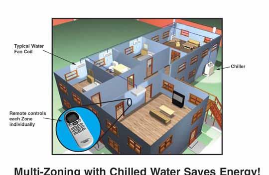
9 Ductless and Ducted Hydronic Air Conditioning & Heating Systems. FOR MULTIZONING FACILITIES Zoning saves energy Better Control of Humidity Separate Climate in each Room 1. More Energy Efficient Thru Zoned Comfort Cooling. 2. Zoning Allows For Diversity. 3. Diversity and Load Calculations Allows For Reducing The Size of The Outdoor Power Plant. 4. Banking Chillers Allows For Huge Efficiencies Thru Staging. 5. Helps Control The Growth Of Mold, Mildew and Fungus. 6. Low Installation Costs. 7. No Refrigerant Handling. 8. No Ductwork No Line Sets. 9. Heat & Cool with the Same Units. 10. No Line Length Limitations. 11. Unlimited Tonnage with Single Phase Power. 12. Easy To Expand System. Think Water!!! 4
10 Water Product Overview Page 44 Page 9 MAC036, 048 & 060 Air Cooled Chiller 3, 4 & 5 Ton Air Cooled Chiller Copeland Scroll Compressor Technology R 407c Refrigerant Horizontal Air Discharge Stainless Steel Pump Included MAC120 Air Cooled Chiller 10 Ton Air Cooled Chiller Copeland Scroll Compressor Technology R 407c Refrigerant Vertical Air Discharge Two Stages of Cooling Page 84 Page 117 MHCCW (Ceiling Concealed) Chilled Water 2-Pipe With or Without Electric Heat 12,000-36,000 BTUH Available with or without Electric Heat Ceiling Concealed Design for Clean Installation Removes Equipment from Conditioned Space Heavy Gauge Metal Cabinet Powder Painted Galvanized Steel Field Reversible Hand of Connection Coil Manual Air Vents Discharge May be Ducted for Small Spaces MHNCCW (Ceiling Concealed) Chilled/Hot Water 4-Pipe 12,000-36,000 BTUH Ceiling Concealed Design for Clean Installation Removes Equipment from Conditioned Space Heavy Gauge Metal Cabinet Powder Painted Galvanized Steel Double Field Reversible Hand of Connection Coil Manual Air Vents Discharge May be Ducted for Small Spaces Page 171 Page 148 MHWW (Hi-Wall) Chilled/Hot Water 2-Pipe 9,000-36,000 BTUH High Wall Mounting Attractive Seamless Appliance Design Cleanable Air Filter Provided Wireless Infrared Remote Included Wired Controller Option MCCW (Ceiling Concealed) Chilled/Hot Water 2-Pipe 48,000 60,000 BTUH Ceiling Concealed Design for Clean Installation Removes Equipment from Conditioned Space Heavy Gauge Metal Cabinet Powder Painted Galvanized Steel Manual Air Vents Discharge May be Ducted for Small Spaces Page 233 Page 207 Page 259 CFFWA Universal Mount Fan Coil 2-Pipe 12,000-60,000 BTUH Floor, Low Wall or Horizontal Ceiling Mounting Attractive Modular Design Cleanable Air Filter Included Optional Wireless Remote 5 CWA2 With or Without Electric Heat 2-Pipe CWA4 Chilled & Hot Water 4-Pipe Available in 2 or 4-Pipe Configuration 18,000-60,000 BTUH Up Flow, Left or Right Hand Horizontal Installation Equipped with R4.2 Insulation CWA2 in 208/ & CWA4 in Electric or Hot Water Heat
11 DX Product Overview DX Fan Coils are Compatible with R410a Refrigerant and are 13 SEER Compatible All DX Coils come Shipped From the Factory with a TXV Installed. MHCCX (Ceiling Concealed) DX 2-Pipe With or Without Electric Heat 12,000-36,000 BTUH Available with or without Electric Heat Ceiling Concealed Design for Clean Installation Removes Equipment from Conditioned Space Heavy Gauge Metal Cabinet Powder Painted Galvanized Steel Field Reversible Hand of Connection Coil TXV Provided Discharge May be Ducted for Small Places 13 SEER Compatible MHNCCX (Ceiling Concealed) DX 4-Pipe with Hot Water 12,000-36,000 BTUH Ceiling Concealed Design for Clean Installation Removes Equipment from Conditioned Space Heavy Gauge Metal Cabinet Powder Painted Galvanized Steel Double Field Reversible Hand of Connection Coil TXV Provided Discharge May Be Ducted for Small Places Hot Water Heating Coil 13 SEER Compatible MCCX (Ceiling Concealed) DX 48,000-60,000 BTUH Ceiling Concealed Design for Clean Installation Removes Equipment from Conditioned Space Heavy Gauge Metal Cabinet Powder Painted Galvanized Steel TXV Provided Discharge May be Ducted for Small Spaces FSFCA (Universal Mount) DX or Heat Pump 12,000-60,000 BTUH Floor, Low Wall or Horizontal Ceiling Mounting Attractive Modular Design Cleanable Air Filter Included Optional Wireless Remote TXV Provided 13 SEER Compatible MHWX (Hi-Wall) DX or Heat Pump 9,000-36,000 BTUH High Wall Mounting Attractive Seamless Appliance Desi Cleanable Air Filter Provided Wireless Infrared Remote Included Wired Control Option 6

12 Accessories Overview Page 385 Page 387 Page 388 Storage Tanks 20 & 42 Gallon Expansion Tank & Air Scoop Liquid Solution Bypass Valve Page 389 Page 395 Page 391 Motorized Valves 2 & 3-Way Wye Strainer Condensate Pump Page 392 Page 396 Page 398 Thermostats Circulating Pumps Enclosures 7
 MAC120 Chillers: 75 dbs (A) Hi-Wall Fan Coils MHWX-09 / MHWW-09: DX and chilled water Hi-Wall fan coils: 42 dbs (A).")
13 January 2008 Multiaqua Equipment Sound Levels The following will detail the Sound Levels of the Multiaqua equipment line. Air Cooled Chillers MAC 036, 048, 060 Chillers: 69 dbs (A) MAC120 Chillers: 75 dbs (A) Hi-Wall Fan Coils MHWX-09 / MHWW-09: DX and chilled water Hi-Wall fan coils: 42 dbs (A). MHWX-12 / MHWW-12: DX and chilled water Hi-Wall fan coils: 43 dbs (A). MHWX-18 / MHWW-18: DX and chilled water Hi-Wall fan coils: 45 dbs (A). MHWX-24 / MHWW-24: DX and chilled water Hi-Wall fan coils: 46 dbs (A). MHWX-36 / MHWW-36: DX and chilled water Hi-Wall fan coils: 48 dbs (A). Universal Mount Fan Coils FSFCA-04 / CFFWA-04: DX and chilled water Universal Mount fan coils: 42 dbs (A). FSFCA-06, 08 / CFFWA-06, 08: DX and chilled water Universal Mount fan coils: 44 dbs (A). FSFCA-10 / CFFWA-10: DX and chilled water Universal Mount fan coils: 46 dbs (A). FSFCA-10, 12 / CFFWA-10, 12: DX and chilled water Universal Mount fan coils: 48 dbs (A). FSFCA-16, 20 / CFFWA-16, 20: DX and chilled water Universal Mount fan coils: 50 dbs (A). Hideaway Fan Coils MHCCX-04 / MHCCW-04: DX / chilled water with electric heat Hideaway fan coils: 42 dbs (A) MHCCX-06 / MHCCW-06: DX / chilled water with electric heat Hideaway fan coils: 44 dbs (A) MHCCX-08 / MHCCW-08: DX / chilled water with electric heat Hideaway fan coils: 46 dbs (A) MHCCX-10 / MHCCW-10: DX / chilled water with electric heat Hideaway fan coils: 48 dbs (A) MHCCX-12 / MHCCW-12: DX / chilled water with electric heat Hideaway fan coils: 49 dbs (A) MHNCCX-04 / MHNCCW-04: DX / chilled water with hot water heat Hideaway fan coil: 40 dbs (A) MHNCCX-06 / MHNCCW-06: DX / chilled water with hot water heat Hideaway fan coil: 42 dbs (A) MHNCCX-08 / MHNCCW-08: DX / chilled water with hot water heat Hideaway fan coil: 44 dbs (A) MHNCCX-10 / MHNCCW-10: DX / chilled water with hot water heat Hideaway fan coil: 46 dbs (A) MHNCCX-12 / MHNCCW-12: DX / chilled water with hot water heat Hideaway fan coil: 48 dbs (A) MCCX-16 / MCCW-16: DX and chilled water Hideaway fan coil. 46 dbs (A) MCCX-20 / MCCW-20: DX and chilled water Hideaway fan coil. 46 dbs (A) Disclaimer: Specifications are subject to change without notice. All tests conducted in nonechoic chambers. Sound levels were measured at five feet from the unit. Levels were measured using free air delivery. 8

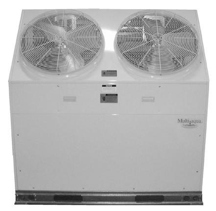
14 MAC120 Air-Cooled Chiller Air-Cooled Chillers for Global Residential and Light Commercial MicroClimates 9
15 MAC120 NOMENCLATURE BREAKDOWN MAC120 - XX - X - R Ton Air-Cooled Chiller Accessory Options N= No Options L= Low Ambient Kit Voltage 01 = 208/ /60 02 = 208/ /60 03 = 380/ /60 Available Model Numbers MAC N-R407 MAC L-R407 MAC N-R407 MAC L-R407 MAC N-R407 MAC L-R407 10
16 HVAC Guide Specifications Air-Cooled Liquid Chiller Nominal Size: 10 Tons Multiaqua Model Number: MAC N-407, MAC L-407 MAC N-407, MAC L-407 MAC N-407, MAC L-407 Part 1-General 1.01 System Description Multiaqua air-cooled liquid chillers are designed using scroll compressors and low sound condenser fans Quality Assurance A. Certified in accordance with U.L. Standard 95, latest version (U.S.A.) B. Construction shall comply with ASHRAE 15 Safety Code, NEC and ASME applicable codes. (U.S.A. Codes) C. Manufactured in a facility registered to ISO 9002, Manufacturing Quality Standard. D. ETL certified. E. Fully load tested at the factory. F. Damage resistant packaging Delivery, Storage and Handling A. Packaged and readied for shipment from the factory. B. Controls shall be capable of withstanding 150 F storage temperatures in the control compartment. C. Stored and handled per manufacturer s recommendations. Part 2-Product 2.01 Equipment A. General: 1. Unit shall be a factory assembled and tested air-cooled liquid chiller. 2. Shall be assembled on heavy gauge steel mounting/lifting rails. 3. Contained within the unit cabinet shall be all factory wiring, piping, controls, refrigerant charge (R407c), POE oil and special accessories required prior to start up. 4. Brass body strainer with 20 mesh screen and blow down shall be supplied in cabinet as a field installable accessory. B. Unit Cabinet: 1. Composed of heavy gauge galvanized steel casing with a baked polyester powder. 2. Capable of withstanding 500-hour salt spray test in accordance with the ASTM (U.S.A.) standard. C. Condenser Fans: 1. 4-blade, aluminum construction and shall be dynamically balanced and corrosion resistant. 2. Discharge air at a 45 vertical angle. 3. Motors and blades shall be protected by coated steel wire safety guards. D. Fan Motors: 1. Condenser fan motors shall be single speed, direct drive. 2. Totally enclosed. 3. Permanently lubricated sleeve bearings and Class F insulation. 4. Internal overload protection. E. Compressors: 1. Unit shall contain two fully hermetic scroll compressors. 2. Direct-drive, 3500 rpm (60Hz) 3. Compressor motor shall be suction gas cooled. 4. Internal motor protection. 5. Externally protected by low and high pressure cutout devices. 6. Individual vibration isolators. 11
17 F. Pump: 1. Unit shall be capable of incorporating a field installed chilled liquid solution pump. (Space restricted) 2. Unit shall have provisions to allow for chilled liquid solution piping to the exterior of the cabinet. G. Evaporator: 1. Evaporator shall have two independent refrigerant circuits. 2. Rated for a refrigerant side working pressure of 450 psig and a maximum water side working pressure of 60 psig. 3. Single pass, ANSI type 316 stainless steel, brazed plate construction. 4. Externally insulated with closed cell, elastomeric foam. (ASTM518) H. Condenser: 1. Condenser coil shall be air-cooled with integral subcooler. 2. Two independent refrigerant circuits. 3. Constructed of rifled copper tubing mechanically bonded to aluminum fins. 4. Cleaned and dehydrated. 5. Factory leak tested to 450 psig. I. Refrigerant Circuits: 1. Each circuit shall contain a sight glass, liquid line filter, thermal expansion valve, refrigerant charge of R407c and POE compressor oil. Part 3-Controls and Safeties 3.01 Controls A. Chiller shall be completely factory wired and tested. B. Capacity control shall be based on leaving chilled liquid solution temperature. 1. Temperature accuracy shall be F. 2. Controls shall be capable of staging the two compressors. C. Controls shall include the following components vac transformer to serve all controllers relays and control components. 2. Microprocessor based liquid solution temperature controller. 3. Leaving water temperature thermistor. 4. Pump bypass timer. 5. Compressor recycle timer. 6. Optional fan cycling control for low ambient operation. 7. Chilled liquid solution flow switch Safeties A. Unit shall be equipped with thermistors and all necessary components in conjunction with the control system to provide the following protectants. 1. Low refrigerant pressure. 2. High refrigerant pressure. 3. Low chilled liquid solution temperature. 4. Low chilled liquid solution flow. 5. Thermal overload. 6. Short cycling. Part 4-Operating Characteristics: 4.01 Temperatures A. Unit shall be capable of starting and running at outdoor temperatures from 55 F to 120 F. B. Optional Low Ambient Kit shall allow starting and running at outdoor temperatures to -20 F. A field supplied and installed crank case heater must be used when operating at these temperatures. C. Unit shall be capable of starting up with a maximum 80 F and a sustained 70 F entering fluid solution temperature to the evaporator. D. Minimum 10% Glycol solution is required. For outdoor temperatures below 32 F, reference MAC Glycol Solution Data table Electrical Requirements A. Primary electrical power supply shall enter the unit at a single location. B. Electrical power supply shall be rated to withstand 120 F operating ambient temperature. C. Units shall be available in 1 or 3-phase power at the voltages shown in the equipment electrical data. D. Control points shall be accessed through terminal block. 12
18 Model Number Model Number MAC120 Product Specifications Physical Data Condenser Coil Chiller Weight (lbs) Copper Tubing Diameter Height Length Coil Height Length Width Refrigerant (in) (in) Rows (in) (in) (in) R407c Net Shipping (in) MAC / oz x MAC / oz x MAC / oz x Electrical Data Volts/ Phase/ Hertz Compressor (Qty 2) 13 Condenser Fan Motor (Qty 2) (RLA) (LRA) (RLA) (RPM) Fuse or HACR Circuit Breaker Minimum Amps MAC / / x x x x 2 See note 1 MAC / / x x x See note 2 MAC /415/ /60 10 x 2 75 x x See note 2 Note: 1. MAC has two independent line voltage terminations. 2. MAC & MAC has one independent line voltage termination. Supply Wire Length in Feet Copper Wire Size (1% Voltage Drop) Supply Circuit Ampacity Compressor Copeland Scroll Refrigerant R407c Heat Exchanger Brazed Plate Max Flow Rate 28.8 gpm Min Flow Rate 18 gpm Supply Water Temp 44 Return Water Temp 54 Minimum System Solution Content 50 Gallons Expansion Tank Size 3% of Total System Water Connections 1 3/8" OD Supply & Return Internal Pressure Drop 18 ft of head Maximum Amps 75 x 2 See note 1 65 See note 2 35 See note 2 Multiaqua chillers are designed to operate exclusively with R407c refrigerant in a self-contained, pre-charged refrigerant system. Do not access the closed refrigerant circuit for any reason other than after-sale, after installation component replacement. Routine maintenance and service is to be performed by qualified personnel only. These specifications are subject to change without notice.
19 MAC120 Product Specifications MAC120 Capacity / Watts / EER* Outdoor Air F TONS KILOWATTS EER * Refrigerant system performance only, pump data not included. MAC120 Glycol Solution Data Propylene Glycol % Water Flow Capacity Min. Ambient Temp GPM Adjustment= 100% Capacity 10% x x F x % x x F x % x x F x % x x F x % x x F x 1.16 Example: 30% glycol solution. Maximum Flow Rate = 12gpm x System capacity x.98 *Use Propylene Glycol Only Important If the outside temperature is expected to fall below freezing (32 F) in the area the Multiaqua chiller is to be installed; the installer must take the following precautions. Failure to do so will void the warranty. To not engage in cold ambient mitigation will result in the failure of components such as the heat exchanger, piping, circulating pump, etc and or property damage. Keep the liquid solution at a minimum of 10% percent Propylene Glycol even in areas where there is no danger of freezing. The percentage amount of glycol recommended is dependent on the expected ambient temperatures and the solution makeup recommendation of the glycol manufacturer. Refer to the MAC120 Glycol Solution Data table above. Ensure the system circulating pump is in a constant energized mode to keep a continuous circulation of liquid solution. The Multiaqua chiller is a self-contained air-cooled condenser, coupled with an insulated brazed plate heat exchanger (evaporator). The system utilizes a scroll compressor to circulate refrigerant between the condenser and heat exchanger. The refrigerant is metered into the heat exchanger with a thermal expansion valve. Protecting the system are high and low pressure switches as well as a pump flow switch. Liquid solution (water and Propylene Glycol; minimum 10 % is required) is circulated through the heat exchanger by an externally mounted pump. The liquid solution flows through the heat exchanger to the system supply piping and on to the air handlers. Low ambient kits are available for operating ambient temperatures down to -20 degrees Fahrenheit. A field supplied and installed crankcase heater must be installed when operating at these temperatures. The low ambient kits consist of an ICM 325 (+) ICM (175) for single and three phase 208/230 vac chillers. For the three phase 380/460 vac chillers a pressure activated fan control is used. These specifications are subject to change without notice. 14
20 MAC120 Cooling Performance Data LWT ( F) MAC120 CAPACITIES with 0% Glycol ENTERING AIR TEMPERATURE ( F) TONS GPM TONS GPM TONS GPM TONS GPM TONS GPM MAC120 CAPACITIES with 10% Glycol LWT ( F) ENTERING AIR TEMPERATURE ( F) TONS GPM TONS GPM TONS GPM TONS GPM TONS GPM MAC120 CAPACITIES with 20% Glycol LWT ( F) ENTERING AIR TEMPERATURE ( F) TONS GPM TONS GPM TONS GPM TONS GPM TONS GPM These specifications are subject to change without notice. 15
21 MAC120 Cooling Performance Data MAC120 CAPACITIES with 30% Glycol LWT ( F) ENTERING AIR TEMPERATURE ( F) TONS GPM TONS GPM TONS GPM TONS GPM TONS GPM MAC120 CAPACITIES with 40% Glycol LWT ( F) ENTERING AIR TEMPERATURE ( F) TONS GPM TONS GPM TONS GPM TONS GPM TONS GPM MAC120 CAPACITIES with 50% Glycol LWT ( F) ENTERING AIR TEMPERATURE ( F) TONS GPM TONS GPM TONS GPM TONS GPM TONS GPM These specifications are subject to change without notice. 16
22 17
23 Table of Contents Page Introduction 19 System Description & Sequence of Operation 20 Electrical & Physical Data 21 Description of Electrical Controls 23 Chiller Controls Sequence of Operation 25 Refrigeration System Operation 26 Description of Refrigeration Components 26 Piping System Components 28 Layout & Design 29 Banked Chiller Configuration 30 Installation Notes 31 Propylene Glycol Content 32 Expansion Tank 32 Filling the System with Propylene Glycol 33 Air Elimination 33 18
24 Multiaqua Chiller Manual The Multiaqua Chiller System is the only air conditioning/refrigeration system of its kind in the world today offering the degree application flexibility described in the following manual. The Multiaqua Chiller System is not only unique in its application flexibility; it is unique in superior quality, rated capacities and rugged durability. When installed in accordance with these instructions the system will deliver years of trouble free service. Proper equipment sizing, piping design and installation are critical to the performance of the chiller. This manual is meant to be a how to introduction to piping and installing the Multiaqua Chiller System. MAC120 Chiller Features Copeland Scroll Compressors Advanced Motor Protection Loss of Flow Protection Control Power Transformer Low Ambient Option Integrated Chilled Solution Pump Control Flow Switch Strainer Connection Kit Painted Metal Condenser Protector Grille Dual Refrigeration Circuits and Single Liquid Solution Circuit RECOGNIZE THIS SYMBOL AS AN INDICATION OF IMPORTANT SAFETY OR INSTRUCTION RELATED INFORMATION. Web site information addresses are supplied throughout this manual for piping and accessory information. The plumbing industry also has pressure drop information on ferrous and copper piping systems. The following sections will describe each component and how it functions within the system. Installation information is supplied where appropriate. The piping design section will explain the design and layout the piping system from a how to perspective. Following the examples provided will enable the installer to determine the correct pipe and accessory sizing, as well as equipment location. It is important to know before installation if the proposed system will operate correctly and by doing a formal layout of a new application or review of an existing piping system will make that determination. Throughout this manual the term liquid solution is used in place of water. The chiller circulates a solution of water and Propylene Glycol. It is essential to operate the system with a minimum of 10% glycol. DO NOT OPERATE THIS SYSTEM USING WATER ALONE. For proper liquid solutions mix ratios, refer to page 14 or the glycol manufacture s recommended mix ratios. 19
25 System Description & Sequence of Operation The Multiaqua Chiller is a self-contained, air-cooled condenser, coupled with an insulated brazed plate heat exchanger (evaporator). The system utilizes scroll compressors to circulate refrigerant between the condenser and heat exchanger. The refrigerant is metered into the heat exchanger with a thermostatic expansion valve. Protecting the system are high and low pressure switches as well as a pump flow switch. Liquid solution (water and Propylene Glycol is circulated through the heat exchanger by a field supplied pump. The liquid solution flows through the heat exchanger to the system supply piping and on to the air handlers. A solenoid-operated, motorized valve or circulator controls the flow of the chilled liquid solution through the air handlers. The valves or circulators can be actuated by a variety of different control schemes. Liquid solution temperature is controlled by a chiller mounted digital electronic controls. A system sequence of operation, individual control description, troubleshooting information and a schematic are included in the controls section. It must be recognized that ferrous pipe may cause acceleration deterioration of the brazed plate heat exchanger and could void the heat exchanger warranty. Cooling load Diversity Equipment sizing for a chilled liquid solution system can utilize Cooling Load Diversity. Diversity is described as the actual amount of cooling needed (heat load) by various sections of a structure at a given time. Conventional air conditioning systems are designed for the highest structure heat load. The conventional system determines and selects equipment based on the peak heat load demanded by the structure. A system sized to take advantage of diversity would determine the heat load by the time of day, building exposure and usage. As an example the sections of a structure facing west, demand more cooling in the afternoon, than sections facing east. The opposite of this is true in the morning, where the east section is exposed to a higher heat load requiring more cooling. Utilizing diversity the chiller system would adapt to the needs of each side of the structure during peak demand by delivering more cooling to that area and less to the areas that do not need it. A structure utilizing a conventional DX system, requires 8 tons of cooling at peak load, could utilize a much smaller capacity system (potentially 4 or 5 tons) if the system installed could take advantage of load diversity, which would supply the necessary amount of cooling to the space, as and when needed instead of keeping a larger capacity available at all times. Cooling load diversity can best be determined by referring to ACCA. (Air Conditioning Contractors of America) Manual J, Refer to the appendix A-2, Multi-Zone Systems. ACCA s Internet address is Because of diversity a Multiaqua Chiller can serve more total air handler tonnage than chiller capacity. A 10-ton chiller may be delivering chilled liquid solution to 15 or more tons of air handler capacity. Because of cooling load diversity, the building does not need equal amounts of cooling in each area at the same time. 20
26 ELECTRICAL AND PHYSICAL DATA The information contained in this manual has been prepared to assist in the proper installation, operation and maintenance of the chiller. Improper installation, or installation not made in accordance with these instructions can result in unsatisfactory operation and/or dangerous conditions and can cause the related warranty not to apply. Read this manual and any instructions packaged with separate equipment required to make up the system prior to installation. Retain this manual for future reference. Separate and independent power supplies and disconnects must be provided. These chillers have separate and discreet power requirements within one cabinet. All power to the chiller must be turned off prior to opening cabinet and or servicing. Failure to properly ground chiller can result in death. Disconnect all power wiring to chiller before maintenance or service work. Failure to do so can cause electrical shock resulting in personal injury or death. All wiring must be done in accordance with the NEC (National Electric Code) as well as state and local codes, by qualified electricians. Product warranty does not cover any damages or defect to the chiller caused by the attachment or use of any components, accessories or devices (other than those authorized by the manufacturer) into, onto or in conjunction with the chiller. You should be aware that the use of unauthorized components, accessories or devices may adversely affect the operation of the chiller and may also endanger life and property. The manufacturer disclaims any responsibility for such loss or injury resulting from the use of such unauthorized components, accessories or devices. Upon receiving the chiller and components, inspect for any shipping damage. Claims for damage, either apparent or concealed should be filed immediately with the shipping company. No liquid other than the solution of water and Propylene Glycol (mixed in accordance with table 6 page 32) shall be used in the piping system. Corrosive environments may subject metal parts of the chiller to rust and deteriorate. The oxidation could shorten the chiller s useful life. Corrosive elements include salt spray, fog or mist in sea coastal areas, sulfur or chlorine from lawn watering systems and various chemical contaminants from industries such as paper mills and petroleum refineries. If the unit is to be installed in an area where contaminates are likely to be a problem, special attention should be given to the equipment location and exposure. Avoid having lawn sprinklers spray directly on the chiller cabinet. In coastal areas, locate the chiller on the side of the building away from the water front. Elevating the chiller off of its slab or base enough to allow air circulation will help avoid holding water in contact with the cabinet base. Regular maintenance will reduce the build-up of contaminants and help protect the cabinet finish. In severe locations having the chiller coated with an epoxy or other coating formulated for air conditioning systems located in coastal areas may be necessary. 21

27 Consult local building codes or ordinances for special installation requirements. When selecting a site to locate the chiller, consider the following: A minimum clearance of 60 on the service access front, 12 on the rear air inlet and a 60 fan discharge clearance. The chiller can be located out or indoors. If installed indoors there must be 9000 cfm of outdoor air changes circulated through the mechanical room to sufficiently operate the chiller. No ductwork can be connected to the chiller s condenser or condenser fans. If a concrete slab is used, do not connect the slab directly to any building s foundation or structure to prevent sound transmission. Locate the slab on a level surface that is above grade to prevent ground water from entering the chiller cabinet. 60 Fan Discharge Clearance Stated Service Clearances 12 Rear Clearance 60 Front Service Clearance 0 Side Clearance Chiller Supply and Return Piping Access
28 Description of Electrical Controls Control Transformer: The control transformer is rated at 24 vac, 40 va (1.6 24vac) Pump Bypass Timer: The pump bypass timer is a 24 vac, 3-wire control. When energized the timer will bypass the flow switch for 10 seconds (by creating a circuit to the pump relay), energizing the pump relay, allowing the pump to operate long enough to close the flow switch. In a normally operating system the flow switch will stay closed powering the pump relay in series with the low and high- pressure switches. Should the flow switch open, the timer can only be reset by opening and closing the chiller's line voltage disconnect. Refrigerant System Timer: The refrigerant timer is a 24 vac, 5-minute delay on break, 20wire timer. The normally closed contacts of the timer energize the compressor contactor through the chilled solution control. When the chilled solution control contacts open, the timer delays by opening its contact for 5- minutes before resetting to the closed position. High Pressure Switch: The high-pressure switch is an automatic reset control that senses compressor discharge line pressure. It opens at 400 PSIG and closes at 300 PSIG. 23
29 Description of Electrical Controls (continued) Low Pressure Switch: The low-pressure switch is an automatic reset control that senses compressor suction line pressure. It opens at 40 PSIG and closes at 80 PSIG. Flow Switch: The flow switch senses liquid solution flow. The paddle of the switch is inserted through a fitting into the pump discharge line. Liquid solution flow deflects the paddle closing the switch. The flow switch is position sensitive. The arrow on the switch must point in the direction of liquid solution flow. Compressor Contactor: The compressor contactor energizes the compressor through the two or three normally open contacts. The contactor coil operates (closes the contacts) when energized by 24 vac. Liquid Solution Temperature Control: The liquid solution temperature control is an adjustable microprocessor based temperature control. This control receives temperature information from a thermistor located on the liquid solution supply line. A liquid crystal display continually indicates liquid solution temperature. The control is mounted inside the chiller cabinet. 24
30 Chiller Controls Sequence of Operation When powered up, the Multiaqua chiller system energizes the control transformer creating 24 vac control voltage. First the pump bypass timer is energized and temporarily bypasses the flow switch, energizing the pump relay. The pump then starts to move liquid solution through the piping system (in a properly filled and air purged system). The movement of liquid solution from the pump discharge keeps the flow switch closed. After a 10 second delay the pump contact opens, connecting the flow switch in series with the high and low pressure switches. The pump will now run continually unless the power supply is interrupted, or the flow switch opens. If the liquid solution temperature controller is calling for cooling the control circuit is routed through the short cycle timer and the three safety switches (the flow, high and low pressure switches) to the compressor contactor. This will energize the compressor(s) and condenser fan motors. The liquid solution controller will open at the user programmed set point, causing the refrigerant short cycle timer to open it's contact for 5 minutes as it delays before resetting to the closed position. This will de-energize the compressor. Power fluctuations will also initiate a 5 minute time delay. The 5 minute delay allows the refrigerant system a period for pressure equalization, protecting the compressor(s) from short cycling. The chiller temperature controller utilizes a thermistor to monitor the liquid solution temperature change. The temperature is then compared to the set point and differential temperatures programmed into the control by the user. The set point is the liquid solution temperature which will cause the control switch to open. For example: The control set point is programmed at 44 F LWT with a 10 F differential, which opens the controller at 44 F LWT and closes at 54 F. The differential temperature is the number of degrees above set point temperature programmed into the controller. If liquid solution temperature falls to the set point, the controller cycles the compressors off. Chillers are shipped with the control set point adjusted to 44 F LWT and a 10 F differential. Liquid solution temperature set point should not be set below 35 F. 25
31 SYSTEM FAULTS: Flow Switch Opening: The flow switch is normally closed during pump operation. Should liquid solution flow be interrupted for any reason, the control will open shutting down and locking out the chiller operation. The only exception to this is when power is first applied to the chiller and the pump bypass timer bypasses the flow switch for 10 seconds. When the system is first filled with liquid solution and the pump is started, expect the system to cycle off on the flow switch until all of the air is removed from the piping system. The system will have to be reset by opening and then closing the disconnect switch or circuit breaker powering the chiller. Low Pressure Switch Opening: Should the compressor suction pressure go low enough (40 PSI) to open the lowpressure switch, the compressor and condenser fan motors will shut down. Check for a refrigerant leak, inoperative thermal expansion valve, low liquid solution control setting, low ambient operation, low liquid solution flow, etc. High Pressure Switch Opening: Should the compressor discharge pressure go high enough to open the high- pressure switch the compressor and condenser fan motors will shut down. Check for a dirty condenser coil, inoperable fan motor(s) or the recirculation of condenser air. Refrigeration System Operation The refrigeration system is a closed loop consisting of 2 compressors, dual circuit heat exchanger (evaporator), metering devices (TXVs) and condenser coil. The refrigerant circulated is R407c. Hot gas is pumped from the compressors to the to the condenser coil where the two condenser fans pull cooler air across the coil condensing and sub cooling the refrigerant. The now liquid refrigerant flows through the liquid line to the thermal expansion valves, where the refrigerant pressure drops causing the refrigerant to boil at a much lower temperature (34-40 F). The refrigerant leaves the expansion valves and swirls through the plates of the heat exchanger absorbing heat from the circulating liquid solution. The evaporator or heat exchanger is designed to operate with an 8-10 F superheat. The condenser is designed to condense the refrigerant and sub cool it to 10 F below condensing temperature. Description Of Refrigerant Components Scroll Compressor: All Multiaqua chillers feature Scroll compressors. Scroll technology ensures reliable high performance at a low sound level over a wide range of operating conditions. Caution the top half of the scroll compressor operates at a temperature high enough to cause serious injury. 26


32 Description Of Refrigerant Components (continued) Brazed Plate Heat Exchanger: The "Heat Exchanger" or evaporator is of a brazed copper and stainless steel design. Refrigerant and liquid solution is channeled through narrow openings between plates and flows in opposite directions. The counter flow design and fluid turbulence ensures maximum heat exchange at minimal pressure drop. Thermal Expansion Valve: Multiaqua chillers are equipped with Thermal Expansion valves. The valves feature a liquid charged sensing bulb for consistent superheat at various load conditions. Condenser Coil: The air-cooled condenser coil is of copper tube with aluminum fin construction. The coil is protected by a painted metal condenser grille. 27

33 Piping System Components Supply Storage Tank: The supply storage tank must be used in the system with less than 25 gallons of liquid solution. The tank prevents rapid cycling of the compressors and acts as a reserve for chilled liquid solution. Supply storage tank must be insulated in the field. Part Number: WX202H (20 Gallon) WX202H (42 Gallon) Expansion Tank and Air Scoop: The Expansion Tank and Air Scoop assembly is used to compensate for the expansion and contraction of liquid in the system. The air scoop eliminates air entrance in the liquid solution. Part Number: 1500/1" Liquid Solution Bypass Valve: The liquid solution bypass valve relieves system pressure from the liquid solution supply to the return as system air handler control are cycled off. Part Number: D146M1032-3/4" D146M /4" Motorized Valve: The air handler motorized valve controls the flow of liquid solution to the systems air handlers. Each air handler in the system should have a motorized or solenoid valve. Part Number: MZV524E-T 1/2" 2-Way Zone Valve MZV525E-T 3/4" 2-Way Zone Valve MZV526E-T 1" 2-Way Zone Valve VT3212G13A020 1/2" 3-Way Zone Valve VT3212G13A020 3/4" 3-Way Zone Valve 28
34 Composite Piping Layout and Design Understanding the function and friction loss of each part of the piping system is important to the layout and successful installation of a chilled liquid solution system Way Liquid Solution Control Valves Bypass Valve Storage Tank Expansion Tank Coil Chiller Pump The circulation pump is the key performer in the piping system. The pump must circulate the liquid solution through the heat exchanger and piping system to the air handlers. Pumps are designed to deliver a flow rate measured in gallons per minute(gpm). The pump must be able to overcome the resistance to flow (pressure drop) imposed by the chiller components, piping system and air handlers while maintain the necessary flow rates in gallons per minute. Pump capacities in gallons per minute and pressure drop (feet of head) are listed in table 1. An adjustable valve must be used to throttle the discharge liquid solution flow rate to appropriate levels based on capacity and glycol mix percentages. Table 1 Chiller System Data MAC Series Min. Liquid Solution Flow Rate Max.Liquid Flow Rate Min. Liquid Solution Content in System Expansion Tank Size Internal Chiller Pressure Loss Chiller Liquid Solution Content GPM GPM Gallons Gallons Ft.of Head Gallons MAC % of Total Piping resistance or pressure drop is measured in feet of head. A foot of head is the amount of pressure drop imposed in lifting liquid solution one foot. Pumps in the Multiaqua system are designed to move rated liquid solution flow (see table 1) in GPMs. 29
35 Banked Chiller Configuration Notes: Installing Multiaqua chillers in parallel is recommended. 30
36 Installation Notes: Piping such as PEX,steel, copper or PVC can be used with the Multiaqua system. Check local building codes for material conformation. Care must be taken when using PVC as the presence of propylene glycol may destroy plastics. Pressure drop data for the selected piping material is readily available and should be used. Should the Multiaqua chiller be installed using existing steel (ferrous metal) piping system, dielectric fittings must be used at the chiller and air handler. The factory supplied wye strainer will capture particles of rust and sediment inherent with steel piping and should be checked and cleaned after initial start up and open a regular maintenance during the life of the system. Any piping used to conduct liquid solution must be insulated in accordance with local and national mechanical codes. Information on insulation installation and application can be obtained from Armaflex web site at and Owens-Corning site at For future servicing of the chiller and air handlers, it is suggested that shutoff valves be installed at the chiller and air handler(s). If ball valves are used, they can double as balancing valve(s) in the supply piping at each air handler. Chiller shutoff valves should be attached at the chiller connections with unions. The air handlers are to be controlled with electrically operated "slow-opening" solenoid valves, circulators or motorized zone valves as manufactured by Erie controls ( A remote thermostat or air handler installed digital control operate the valves. Bypass valves as shown in drawing 1, should be installed between the supply and the return chilled liquid solution supply pipes at a convenient location to the installation. The bypass valve operates to bypass liquid solution between the supply and return chilled liquid solution lines. In the event air handlers valves should shut down, the bypass valve is set to open up and bypass liquid solution between the supply and return lines, relieving pressure and eliminating the possibility of pump cavitations. To adjust the valve, run the system with one air handler solenoid actuated. De-energize the solenoid valve, (at this point no liquid solution will be flowing through the air handlers.) and adjust the bypass valve to relieve pressure between the supply and return piping. Bleed ports will be factory installed on all Multiaqua air handlers. Bleed ports are opened to eliminate air trapped in the air handlers after filling the system with liquid solution and Propylene Glycol and before operating the refrigerant compressor in the chiller. The minimum liquid solution content in the chiller system,(piping, chiller, and air handlers), is 50 U.S. gallons. Estimate the system liquid solution content. Should the system have less than 50 gallons of liquid solution content, a chilled liquid solution storage tank must be installed. The tank stores enough chilled liquid solution to prevent frequent chiller compressor cycles at light load and prevents chilled liquid temperature swings at higher load conditions when the chiller compressor is waiting to cycle on the time delay control. Propylene Glycol must be added to the water used in the system. Propylene helps prevent freeze-ups due to low ambient temperature conditions and low chilled liquid solution temperatures. In comparison to water, Propylene Glycol slightly lessons the temperature exchange in the chiller heat exchanger. However, that is offset by the increased flow of liquid solution through the piping system enabled by the Propylene Glycol. To determine the Propylene Glycol content for various ambient temperatures refer to table 6 page 32. In no instance should a Multiaqua chiller be installed with less than 10% Propylene Glycol content in the piping system. Using less than the recommended Propylene Glycol percentage content voids equipment warranty. 31

37 Polypropylene Glycol System Content vs. Minimum Ambient Temperature To not engage in cold ambient mitigation will result in the failure of components, property damage and void warranty. Table 6 Percent of Propylene Glycol to Water Content Propylene Water Min. Ambient Capacity Glycol % Flow Temperature 10% x x F 20% x x F 30% x x.98 8 F 40% x x.97-7 F 50% x x F GPM Adjustment = 100 % Capacity x 1.01 x 1.03 x 1.07 x 1.11 x 1.16 Ethylene Glycol is environmentally hazardous and not recommended. Inhibited Propylene Glycol ( typical automotive coolant) is not to be used in a Multiaqua Chiller under any circumstances. Dow Chemical's "Ambitrol" family of Glycol-based coolants of food grade Propylene Glycol is suggested. Information on Ambitrol is available from Dow at search word "Ambitrol". Expansion Tanks: Liquid solution expansion and contraction within the closed system must be compensated for with an expansion tank. The expansion tank used with the Multiaqua system, is a steel tank with a rubber bladder attached to it internally. There is air pressure on one side of the rubber bladder that keeps the bladder pushed against the sides of the tank before the system is filled with liquid solution (illustration above). As the liquid solution heats up the bladder will be pushed further away from the tank walls, allowing for expansion and contracting as the liquid solution temperature changes. By flexing, the bladder controls the system pressure adjusting to temperature variations of the chilled liquid solution system. It is critical that the expansion tank's air bladders pressure be less than the system solution pressure. Air pressure can be measured with an automotive tire gauge at the bicycle valve port on the expansion tank. Bleeding air out of the bladder or increasing the pressure with a bicycle pump will adjust pressure. System must use a liquid solution storage tank if system volume is less than 50 U.S. gallons. 32
38 Filling System with Liquid Solution and Coolant (Propylene Glycol) Before filling system with Propylene Glycol and water, pressure test the piping system with compressed air. Testing should be done at a maximum of 50 psi.the system should hold air pressure for a minimum of one hour with no leakage. Concentrations of Propylene Glycol in excess of 50% will destroy o-rings in fittings and pump. Water should be added to the system first or a liquid solution diluted Propylene Glycol mix. System that contains 50 or more U.S. gallons should have a tee fitting with a stopcock installed in the return line close to the chiller. The stopcock can be opened and attached to a hose with a female X female hose fitting. In the open end of the hose section (1-1.5 feet long) insert a funnel and pour into the system the diluted Propylene Glycol/liquid solution mixture or add water first and then the quantity of Propylene Glycol needed for minimum ambient protection (refer to Table 6). After adding the Propylene Glycol/water mixture, or liquid solution and then coolant proceed to add enough water to the system to achieve a 15 psi gauge pressure. To measure system pressure shut off the stopcock, remove hose and attach a water pressure gauge. Open the stopcock to read system pressure. Systems that use the Chilled Liquid Solution Storage Tank should be filled at the tee/stopcock fitting in the outlet fitting of the storage tank. Fill the tanks with 10 gallons of water and with a funnel pour the calculated (refer to Table 6) amount of Propylene Glycol into the tank. The amount of Propylene Glycol added should be calculated to achieve minimum ambient protection. After adding Propylene Glycol, fill the system with enough liquid solution to bring system pressure to approximately 15 psi gauge pressure. To measure system pressure shut off the stopcock and attach a water pressure gauge. Open the stopcock to read system pressure. Air Elimination Since we have the system filled we must eliminate the air left in the system. Briefly open each bleed valve at the air handlers and allow trapped air to escape. This will eliminate much of the air left in the system. Next we will start the pump and continue bleeding air from the system. Be sure the chiller has line voltage available to it and set the chilled liquid solution control up to 100 F, which will ensure that only the pump runs at this point. The pump should now start and remain running. Should the pump stop at any time during this process it is an indication that the flow switch had air move across it allowing the circuit to be interrupted. Continue to bleed some air out of the system at the highest locations before resetting the pump bypass timer to get the pump running again. Open and close the power supply switch to the chiller to restart the pump. Continue bleeding air with the pump operating. You may have to start and re-start the pump a few times to complete air removal. If you continue having air entrapment issues, it will be necessary to install a micro bubble remover device. All piping systems should have a minimum of 10% Propylene Glycol in the system even in climates with nonfreezing ambient temperatures. Using less than the recommended Propylene Glycol percentage content voids equipment warranty. Liquid solution control valves (solenoid or motorized valves) should be selected for low pressure drop. If a selected valve contributes to pushing your total head calculation to more than 50 feet of head, a larger valve may be needed to bring your total head below the maximum of 50 feet. Liquid Solution Balancing: Liquid solution balancing will require an accurate digital thermometer to measure return line liquid solution temperature at each air handler. Set the chilled liquid solution temperature control in the chiller at a normal operational temperature (44 F) and measure pump discharge temperature with the digital thermometer to check system solution temperature. After the chilled liquid solution temperature has lowered to the set point begin the balancing process. The system must be free of air and each air handler set at a temperature low enough to continue cooling operation (and liquid solution flow) during the balancing process. Begin by measuring the return line chilled liquid solution temperature of each air handler. Begin incrementally closing the supply line balance valve at the air handlers with the lowest return line chilled liquid solution temperature. Continue this process until each air handler has close to the same return line chilled liquid solution temperature. 33
39 MAC120-3 Ladder Wiring Diagram 380/ /60 34
40 MAC120-3 Wiring Diagram 380/ /60 MULTIAQUA BL 380/ /60 BK L1 RD L2 BK CON1` BK BK RD WH T1 COMP T2 1 T3 BK BK 380/460-3 TRANSFORMER 24 vac BL YL YL RD BK BL FS LPS1 BL GND L3 WH CON2 BK RD WH T1 T2 T3 COMP BK BK HPS1 BK BK TIMER1 BK BK BK WH REL 1 REL 2 BK BK BK 2 TM2 1 NOTE BL LPS2 BL BL BL 3 4 BL BL DTC 1 NO C DTC 2 NO C BK BL BK BK HPS2 BK 24 vac COM 24 vac WH WH BK COM BK FC1 BK FAN 1 FC2 FAN 2 BK BK 2 TM2 1 RD WH TITLE AUTHOR MAC / /60 kjg LEGEND: FACTORY WIRING FIELD WIRING CON COMPRESSOR CONTACTOR FS FLOW SWITCH LPS LOW PRESSURE SWITCH NOTES: 1.PUMP STARTER RELAY DATE REVISION 09/22/ REV 1 DTC DIGITAL TEMPERATURE CONTROLLER FC CONDENSER FAN CONTACTOR REL CONDENSER FAN RELAY HPS TIMER TM2 HIGH PRESSURE SWITCH PUMP BYPASS TIMER REFRIGERANT SYSTEM TIMER 35
41 MAC120-3-L with Low Ambient Kit Wiring Diagram 380/460/-3-50/60 MULTIAQUA 380/ /60 BK L1 RD L2 BK CON1` BK BK RD WH BL T1 COMP T2 1 T3 BK BK 380/460-3 TRANSFORMER 24 vac BL YL YL RD BK BL FS LPS1 BL GND L3 WH CON2 BK RD WH T1 T2 T3 COMP BK BK HPS1 BK BK TIMER1 BK BK BK NOTE 1 REL 1 REL 2 BK BK BK 2 TM2 1 FAN CYCLE PRESSURE SWITCH 1 2 BL LPS2 BL 3 4 FAN CYCLE PRESSURE SWITCH BL BL DTC 1 NO C DTC 2 NO C 24 vac COM 24 vac COM FC1 NOTE 2 BL 1 FAN BK FC2 4 FAN BK BK BK HPS2 2 TM2 1 BK NOTE 3 TITLE AUTHOR DATE REVISION MAC WITH LOW AMBIENT KIT kjg 09/22/ REV 1 LEGEND: FACTORY WIRING FIELD WIRING DTC DIGITAL TEMPERATURE CONTROLLER FC CONDENSER FAN CONTACTOR REL CONDENSER FAN RELAY CON FS LPS HPS TIMER TM2 COMPRESSOR CONTACTOR FLOW SWITCH LOW PRESSURE SWITCH HIGH PRESSURE SWITCH PUMP BYPASS TIMER REFRIGERANT SYSTEM TIMER NOTES: 1. PUMP STARTER RELAY 2. LOW AMBIENT RELAY #1 3. LOW AMBIENT RELAY #2 36
42 MAC120-2 Ladder Wiring Diagram 208/ /60 37
43 MAC120-2 Wiring Diagram 208/ /60 38
44 MAC120-2-L with Low Ambient Kit Wiring Diagram 208/ /60 39
45 MAC120-1 Ladder Wiring Diagram 208/ /60 40
46 MAC120-1 Wiring Diagram 208/ /60 41
47 MAC120-1-L with Low Ambient Kit Wiring Diagram 208/ /60 42
48 MAC120 CERTIFIED DRAWING 43
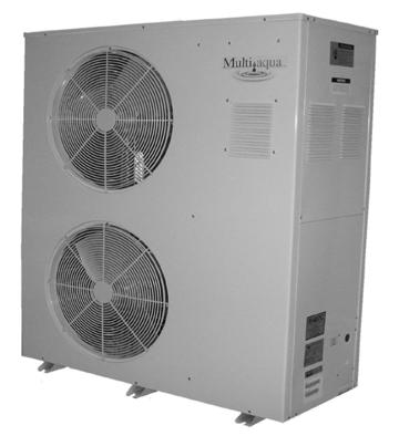
49 MAC036,048 & 060 Air-Cooled Chiller Air-Cooled Chillers for Global Residential and Light Commercial MicroClimates 44
50 MAC036,048 & 060 NOMENCLATURE BREAKDOWN MACXXX - XX - X Air-Cooled Chiller 036= 36,0000 BTUH 048= 48,0000 BTUH 060= 60,0000 BTUH Accessory Options N= No Options L= Low Ambient Kit Voltage 01 = 208/ /60 02 = 208/ /60 03 = 380/ /60 Available Model Numbers MAC N MAC L MAC N MAC L MAC N MAC L MAC N MAC L MAC N MAC L MAC N MAC L MAC N MAC L 45
51 HVAC Guide Specifications Air-Cooled Liquid Chiller Nominal Size: 3, 4 & 5 Tons Multiaqua Model Number: MAC N-407, MAC L-407: MAC N-407, MAC L-407, MAC N-407, MAC L-407: MAC N-407, MAC L-407, MAC N-407, MAC L-407, MAC N-407, MAC L-407, Part 1-General 1.01 System Description Multiaqua air-cooled liquid chillers are designed using scroll compressors, low sound condenser fans and high efficiency pumps Quality Assurance A. Certified in accordance with U.L. Standard 95, latest version (U.S.A.) B. Construction shall comply with ASHRAE 15 Safety Code, NEC and ASME applicable codes. (U.S.A. Codes) C. Manufactured in a facility registered to ISO 9002, Manufacturing Quality Standard. D. ETL Certified E. Fully load tested at the factory. F. Damage resistant packaging Delivery, Storage and Handling A. Packaged and readied for shipment from the factory. B. Controls shall be capable of withstanding 150 F storage temperatures in the control compartment. C. Stored and handled per manufacturer s recommendations. Part 2-Product 2.01 Equipment A. General: 1. Unit shall be a factory assembled and tested air-cooled liquid chiller. 2. Shall be assembled on heavy gauge steel mounting/lifting rails. 3. Contained within the unit cabinet shall be all factory wiring, piping, controls, refrigerant charge (R407c), POE oil and special accessories required prior to start up. 4. Brass body strainer with 20 mesh screen and blow down shall be supplied in cabinet as a field installable accessory. B. Unit Cabinet: 1. Composed of heavy gauge galvanized steel casing with a baked polyester powder. 2. Capable of withstanding 500-hour salt spray test in accordance with the ASTM (USA) standard. C. Condenser Fans: 1. 4-blade, aluminum construction and shall be dynamically balanced and corrosion resistant. 2. Horizontal discharged air. 3. Motors and blades shall be protected by coated steel wire safety guards. D. Fan Motors: 1. Condenser fan motors shall be single speed, direct drive. 2. Totally enclosed. 3. Permanently lubricated sleeve bearings and Class F insulation. 4. Internal overload protection. E. Compressors: 1. Unit shall contain one fully hermetic scroll compressors. 2. Direct-drive, 3500 rpm (60Hz) 3. Compressor motor shall be suction gas cooled. 4. Internal motor protection. 5. Externally protected by low and high pressure cutout devices. 6. Individual vibration isolators. 46
52 F. Pump: 1. Circulating pump shall be stainless steel with high efficiency enclosed motor. 2. Unit shall have chilled liquid solution piping to the exterior of the cabinet. G. Evaporator: 1. Evaporator shall have one independent refrigerant circuit and one liquid solution circuit. 2. Rated for a refrigerant side working pressure of 450 psig and a maximum water side working pressure of 150 psig. 3. Single pass, ANSI type 316 stainless steel, brazed plate construction. 4. Externally insulated with closed cell, elastomeric foam. (ASTM518) H. Condenser: 1. Condenser coil shall be air-cooled with integral subcooler. 2. One independent refrigerant circuit. 3. Constructed of rifled copper tubing mechanically bonded to aluminum fins. 4. Cleaned and dehydrated. 5. Factory leak tested to 450 psig. I. Refrigerant Circuits: 1. Each circuit shall contain a sight glass, liquid line filter, thermal expansion valve, refrigerant charge of R407c and POE compressor oil. Part 3-Controls and Safeties 3.01 Controls A. Chiller shall be completely factory wired and tested. B. Capacity control shall be based on leaving chilled liquid solution temperature. 1. Temperature accuracy shall be F. 2. Controls shall be capable of staging the two compressors. C. Controls shall include the following components vac transformer to serve all controllers relays and control components. 2. Microprocessor based liquid solution temperature controller. 3. Leaving water temperature thermistor. 4. Pump bypass timer. 5. Compressor recycle timer. 6. Optional low pressure bypass timer for low ambient operation. 7. Optional fan cycling control for low ambient operation. 8. Chilled liquid solution flow switch Safeties A. Unit shall be equipped with thermistors and all necessary components in conjunction with the control system to provide the following protectants. 1. Low refrigerant pressure. 2. High refrigerant pressure. 3. Low chilled liquid solution temperature. 4. Low chilled liquid solution flow. 5. Thermal overload. 6. Short cycling. Part 4-Operating Characteristics: 4.01 Temperatures A. Unit shall be capable of starting and running at outdoor temperatures from 55 F to 120 F. B. Optional Low Ambient Kit shall allow starting and running at outdoor temperatures to -20 F. A field supplied and installed crankcase heater must be used when operating at these temperatures. C. Unit shall be capable of starting up with a maximum 80 F and a sustained 70 F entering fluid solution temperature to the evaporator. D. Minimum 10% Glycol solution is required. For outdoor temperatures below 32 F, reference MAC Glycol Solution Data table Electrical Requirements A. Primary electrical power supply shall enter the unit at a single location. B. Electrical power supply shall be rated to withstand 120 F operating ambient temperature. C. Units shall be available in 1 or 3-phase power at the voltages shown in the equipment electrical data. D. Control points shall be accessed through terminal block. 47
53 Model Number Model Number Height (in) MAC036, 048 & 060 Product Specifications Physical Data Coil Chiller Weight (lbs) Copper Length Coil Height Length Width Refrigerant Diameter Net Shipping (in) Rows (in) (in) (in) R407c (in) MAC / oz MAC / oz MAC / oz Volts/ Phase/ Hertz Electrical Data Condenser Compressor Fan Motor (2 qty) Pump Motor Fuse or HACR Circuit Breaker Per Circuit (RLA) (LRA) (FLA) (RPM) (FLA) (RPM) Minimum Amps MAC / / MAC / / MAC / / MAC / / MAC / / MAC / / MAC / / Maximum Amps MAC036 MAC048 MAC060 Compressor Copeland Copeland Copeland Scroll Scroll Scroll Refrigerant R407c R407c R407c Heat Exchanger Brazed Plate Brazed Plate Brazed Plate Max. Head Pressure 50 ft. 50 ft. 50 ft. Max Flow Rate 8.6 gpm 11.5 gpm 14.4 gpm Min Flow Rate 5.5 gpm 6.5 gpm 9.0 gpm Supply Water Temp Return Water Temp Min. Solution Content 25 Gallons 25 Gallons 25 Gallons Expansion Tank Size 2 Gallons 2 Gallons 2 Gallons Pump 0.5 HP 0.5 HP 0.5 HP Water Connections 1" S & 1.25" R 1" S & 1.25" R 1" S & 1.25" R Internal Pressure loss 1.77 ft of head 1.68 ft of head 1.85 ft of head Supply Wire Length in Feet Copper Wire Size (1% Voltage Drop) Supply Circuit Ampacity Multiaqua chillers are designed to operate exclusively with R407c refrigerant in a self-contained, pre-charged refrigerant system. Do not access the closed refrigerant circuit for any reason other than after-sale, after installation component replacement. Routine maintenance and service is to be performed by qualified personnel only. These specifications are subject to change without notice. 48
54 MAC036, 048 & 060 Product Specifications MAC036, 048 & 060 Capacity / Watts / EER MAC036 MAC048 MAC060 O/A Temp ( F) Tons KW EER Tons KW EER Tons KW EER Glycol Solution Data Propylene Glycol % Water Flow Capacity Min. Ambient Temp GPM Adjustment= 100% Capacity 10% x x F x % x x F x % x x F x % x x F x % x x F x 1.16 Example: 30% glycol solution. Maximum Flow Rate = 12gpm x System capacity x.98 Use Propylene Glycol Only Important If the outside temperature is expected to fall below freezing (32 F) in the area the Multiaqua chiller is to be installed; the installer must take the following precautions. Failure to do so will void the warranty. To not engage in cold ambient mitigation will result in the failure of components such as the heat exchanger, piping, circulating pump, etc and or property damage. Keep the liquid solution at a minimum of ten percent propylene glycol even in areas where there is no danger of freezing. The percentage amount of glycol recommended is dependent on the expected ambient temperatures and the solution makeup recommendation of the glycol manufacturer. Refer to the Glycol Solution Data table above. Ensure the system circulating pump is in a constant energized mode to keep a continuous circulation of liquid solution. The Multiaqua chiller is a self-contained air-cooled condenser, coupled with an insulated brazed plate heat exchanger (evaporator). The system utilizes a scroll compressor to circulate refrigerant between the condenser and heat exchanger. The refrigerant is metered into the heat exchanger with a thermostatic expansion valve. Protecting the system are high and low pressure switches as well as a pump flow switch. Liquid solution (water and propylene glycol; minimum 10 % is required) is circulated through the heat exchanger by an externally mounted pump. The liquid solution flows through the heat exchanger to the system supply piping and on to the air handlers. Low ambient kits are available for operating ambient temperatures down to 0 degrees Fahrenheit. The low ambient kits consist of an ICM 325 (+) ICM (175) for single and three phase 208/230 vac chillers. For the three phase 380/460 vac chillers a pressure activated fan control is used. These specifications are subject to change without notice. 49
55 MAC036 Cooling Performance Data LWT ( F) MAC036 CAPACITIES with 0% Glycol ENTERING AIR TEMPERATURE ( F) TONS GPM TONS GPM TONS GPM TONS GPM TONS GPM MAC036 CAPACITIES with 10% Glycol LWT ( F) ENTERING AIR TEMPERATURE ( F) TONS GPM TONS GPM TONS GPM TONS GPM TONS GPM MAC036 CAPACITIES with 20% Glycol LWT ( F) ENTERING AIR TEMPERATURE ( F) TONS GPM TONS GPM TONS GPM TONS GPM TONS GPM These specifications are subject to change without notice. 50
56 MAC036 Cooling Performance Data MAC036 CAPACITIES with 30% Glycol LWT ( F) ENTERING AIR TEMPERATURE ( F) TONS GPM TONS GPM TONS GPM TONS GPM TONS GPM MAC036 CAPACITIES with 40% Glycol LWT ( F) ENTERING AIR TEMPERATURE ( F) TONS GPM TONS GPM TONS GPM TONS GPM TONS GPM MAC036 CAPACITIES with 50% Glycol LWT ( F) ENTERING AIR TEMPERATURE ( F) TONS GPM TONS GPM TONS GPM TONS GPM TONS GPM These specifications are subject to change without notice. 51
57 MAC048 Cooling Performance Data LWT ( F) MAC048 CAPACITIES with 0% Glycol ENTERING AIR TEMPERATURE ( F) TONS GPM TONS GPM TONS GPM TONS GPM TONS GPM MAC048 CAPACITIES with 10% Glycol LWT ( F) ENTERING AIR TEMPERATURE ( F) TONS GPM TONS GPM TONS GPM TONS GPM TONS GPM MAC048 CAPACITIES with 20% Glycol LWT ( F) ENTERING AIR TEMPERATURE ( F) TONS GPM TONS GPM TONS GPM TONS GPM TONS GPM These specifications are subject to change without notice. 52
58 MAC048 Cooling Performance Data MAC048 CAPACITIES with 30% Glycol LWT ( F) ENTERING AIR TEMPERATURE ( F) TONS GPM TONS GPM TONS GPM TONS GPM TONS GPM MAC048 CAPACITIES with 40% Glycol LWT ( F) ENTERING AIR TEMPERATURE ( F) TONS GPM TONS GPM TONS GPM TONS GPM TONS GPM MAC048 CAPACITIES with 50% Glycol LWT ( F) ENTERING AIR TEMPERATURE ( F) TONS GPM TONS GPM TONS GPM TONS GPM TONS GPM These specifications are subject to change without notice. 53
59 MAC060 Cooling Performance Data MAC060 CAPACITIES with 0% Glycol LWT ( F) ENTERING AIR TEMPERATURE ( F) TONS GPM TONS GPM TONS GPM TONS GPM TONS GPM MAC060 CAPACITIES with 10% Glycol LWT ( F) ENTERING AIR TEMPERATURE ( F) TONS GPM TONS GPM TONS GPM TONS GPM TONS GPM MAC060 CAPACITIES with 20% Glycol LWT ( F) ENTERING AIR TEMPERATURE ( F) TONS GPM TONS GPM TONS GPM TONS GPM TONS GPM These specifications are subject to change without notice. 54
60 MAC060 Cooling Performance Data LWT ( F) MAC060 CAPACITIES with 30% Glycol ENTERING AIR TEMPERATURE ( F) TONS GPM TONS GPM TONS GPM TONS GPM TONS GPM MAC060 CAPACITIES with 40% Glycol LWT ( F) ENTERING AIR TEMPERATURE ( F) TONS GPM TONS GPM TONS GPM TONS GPM TONS GPM MAC060 CAPACITIES with 50% Glycol LWT ( F) ENTERING AIR TEMPERATURE ( F) TONS GPM TONS GPM TONS GPM TONS GPM TONS GPM These specifications are subject to change without notice. 55
61 MAC 036, 048 & 060 Chiller Pump Curve Pump Model Numbers SSP-1 = 208/ /60 SSP-2 = 208/230/ / Horsepower 56
62 57
63 Table of Contents Page Introduction 59 System Description & Sequence of Operation 60 Electrical & Physical Data 61 Description of Electrical Controls 63 Chiller Controls Sequence of Operation 65 Refrigeration System Operation 66 Description of Refrigeration Components 66 Piping System Components 68 Layout & Design 69 Banked Chiller Configuration 69 Installation Notes 71 Propylene Glycol Content 72 Expansion Tank 72 Filling the System with Propylene Glycol 73 Air Elimination 73 58
64 Multiaqua Chiller Manual The Multiaqua Chiller System is the only air conditioning/refrigeration system of its kind in the world today offering the degree application flexibility described in the following manual. The Multiaqua Chiller System is not only unique in its application flexibility; it is unique in superior quality, rated capacities and rugged durability. When installed in accordance with these instructions the system will deliver years of trouble free service. Proper equipment sizing, piping design and installation are critical to the performance of the chiller. This manual is meant to be a how to introduction to piping and installing the Multiaqua Chiller System. MAC036, 048 & 060 Chiller Features Copeland Scroll Compressors Stainless Steel Pump Advanced Motor Protection Loss of Flow Protection Control Power Transformer Low Ambient Option Integrated Chilled Solution Pump Control Flow Switch Strainer Connection Kit Painted Metal Condenser Protector Grille Single Refrigeration Circuits and Single Liquid Solution Circuit RECOGNIZE THIS SYMBOL AS AN INDICATION OF IMPORTANT SAFETY OR INSTRUCTION RELATED INFORMATION. Web site information addresses are supplied throughout this manual for piping and accessory information. The plumbing industry also has pressure drop information on ferrous and copper piping systems. The following sections will describe each component and how it functions within the system. Installation information is supplied where appropriate. The piping design section will explain the design and layout the piping system from a how to perspective. Following the examples provided will enable the installer to determine the correct pipe and accessory sizing, as well as equipment location. It is important to know before installation if the proposed system will operate correctly and by doing a formal layout of a new application or review of an existing piping system will make that determination. Throughout this manual the term liquid solution is used in place of water. The chiller circulates a solution of water and Propylene Glycol. It is essential to operate the system with a minimum of 10% glycol. DO NOT OPERATE THIS SYSTEM USING WATER ALONE. For proper liquid solutions mix ratios, refer to table 6, page 72 or the glycol manufacture s recommended mix ratios. 59
65 System Description & Sequence of Operation The Multiaqua Chiller is a self-contained, air-cooled condenser, coupled with an insulated brazed plate heat exchanger (evaporator). The system utilizes a scroll compressor to circulate refrigerant between the condenser and heat exchanger. The refrigerant is metered into the heat exchanger with a thermostatic expansion valve. Protecting the system are high and low pressure switches as well as a pump flow switch. Liquid solution (water and propylene glycol) is circulated through the heat exchanger by a factory supplied internal pump. The liquid solution flows through the heat exchanger to the system supply piping and on to the air handlers. A solenoid-operated, motorized valve or circulator controls the flow of the chilled liquid solution through the air handlers. The valves or circulators can be actuated by a variety of different control schemes. Liquid solution temperature is controlled by a chiller mounted digital electronic controls. A system sequence of operation, individual control description, troubleshooting information and a schematic are included in the controls section. It must be recognized that ferrous pipe may cause acceleration deterioration of the brazed plate heat exchanger and could void the heat exchanger warranty. Cooling Diversity Load Equipment sizing for a chilled liquid solution system can utilize Cooling Load Diversity. Diversity is described as the actual amount of cooling needed (heat load) by various sections of a structure at a given time. Conventional air conditioning systems are designed for the highest structure heat load. The conventional system determines and selects equipment based on the peak heat load demanded by the structure. A system sized to take advantage of diversity would determine the heat load by the time of day, building exposure and usage. As an example the sections of a structure facing west, demand more cooling in the afternoon, than sections facing east. The opposite of this is true in the morning, where the east section is exposed to a higher heat load requiring more cooling. Utilizing diversity the chiller system would adapt to the needs of each side of the structure during peak demand by delivering more cooling to that area and less to the areas that do not need it. A structure utilizing a conventional DX system, requires 8 tons of cooling at peak load, could utilize a much smaller capacity system (potentially 4 or 5 tons) if the system installed could take advantage of load diversity, which would supply the necessary amount of cooling to the space, as and when needed instead of keeping a larger capacity available at all times. Cooling load diversity can best be determined by referring to ACCA. (Air Conditioning Contractors of America) Manual J, Refer to the appendix A-2, Multi-Zone Systems. ACCA s Internet address is Because of diversity a Multiaqua Chiller can serve more total air handler tonnage than chiller capacity. For example, a 5-ton chiller may be delivering chilled liquid solution to 7 or more tons of air handler capacity. Because of cooling load diversity, the building does not need equal amounts of cooling in each area at the same time. 60
66 ELECTRICAL AND PHYSICAL DATA The information contained in this manual has been prepared to assist in the proper installation, operation and maintenance of the chiller. Improper installation, or installation not made in accordance with these instructions can result in unsatisfactory operation and/or dangerous conditions and can cause the related warranty not to apply. Read this manual and any instructions packaged with separate equipment required to make up the system prior to installation. Retain this manual for future reference. Separate and independent power supplies and disconnects must be provided. These chillers have separate and discreet power requirements within one cabinet. All power to the chiller must be turned off prior to opening cabinet and or servicing. Failure to properly ground chiller can result in death. Disconnect all power wiring to chiller before maintenance or service work. Failure to do so can cause electrical shock resulting in personal injury or death. All wiring must be done in accordance with the NEC (National Electric Code) as well as state and local codes, by qualified electricians. Product warranty does not cover any damages or defect to the chiller caused by the attachment or use of any components, accessories or devices (other than those authorized by the manufacturer) into, onto or in conjunction with the chiller. You should be aware that the use of unauthorized components, accessories or devices may adversely affect the operation of the chiller and may also endanger life and property. The manufacturer disclaims any responsibility for such loss or injury resulting from the use of such unauthorized components, accessories or devices. Upon receiving the chiller and components, inspect for any shipping damage. Claims for damage, either apparent or concealed should be filed immediately with the shipping company. No liquid other than the solution of water and propylene glycol (mixed in accordance with table 6) shall be used in the piping system. Corrosive environments may subject metal parts of the chiller to rust and deteriorate. The oxidation could shorten the chiller s useful life. Corrosive elements include salt spray, fog or mist in sea coastal areas, sulfur or chlorine from lawn watering systems and various chemical contaminants from industries such as paper mills and petroleum refineries. If the unit is to be installed in an area where contaminates are likely to be a problem, special attention should be given to the equipment location and exposure. Avoid having lawn sprinklers spray directly on the chiller cabinet. In coastal areas, locate the chiller on the side of the building away from the water front. Elevating the chiller off of its slab or base enough to allow air circulation will help avoid holding water in contact with the cabinet base. Regular maintenance will reduce the build-up of contaminants and help protect the cabinet finish. In severe locations having the chiller coated with an epoxy or other coating formulated for air conditioning systems located in coastal areas may be necessary. 61

67 Consult local building codes or ordinances for special installation requirements. When selecting a site to locate the chiller, consider the following: A minimum clearance of 60 on the front fan discharge, 12 on the rear air inlet and a 24 clearance is required on the service side. The chiller can be located out or indoors. If installed indoors there must be 4500 cfm of outdoor air changes circulated through the mechanical room to sufficiently operate the chiller. No ductwork can be connected to the chiller s condenser or condenser fans. If a concrete slab is used, do not connect the slab directly to any building s foundation or structure to prevent sound transmission. Locate the slab on a level surface that is above grade to prevent ground water from entering the chiller cabinet. Stated Service Clearances 12 Rear Clearance 60 Front Fan Discharge Clearance 24 Side Service Clearance Return Liquid Solution Connection Service Access Electrical Connection Supply Liquid Solution Connection 62
, energizing the pump relay, allowing the pump to operate long enough to close the flow")


68 Description of Electrical Controls Control Transformer: The control transformer is rated at 24 vac, 40 va (1.6 24vac) Pump Bypass Timer: The pump bypass timer is a 24 vac, 3-wire control. When energized the timer will bypass the flow switch for 10 seconds (by creating a circuit to the pump relay), energizing the pump relay, allowing the pump to operate long enough to close the flow switch. In a normally operating system the flow switch will stay closed powering the pump relay in series with the low and high- pressure switches. Should the flow switch open, the timer can only be reset by opening and closing the chiller's line voltage disconnect. Refrigerant System Timer: The refrigerant timer is a 24 vac, 5-minute delay on break, 20wire timer. The normally closed contacts of the timer energize the compressor contactor through the chilled solution control. When the chilled solution control contacts open, the timer delays by opening its contact for 5- minutes before resetting to the closed position. High Pressure Switch: The high-pressure switch is an automatic reset control that senses compressor discharge line pressure. It opens at 400 PSIG and closes at 300 PSIG. 63


 when energized by 24 vac.")
69 Description of Electrical Controls (continued) Low Pressure Switch: The low-pressure switch is an automatic reset control that senses compressor suction line pressure. It opens at 40 PSIG and closes at 80 PSIG. Flow Switch: The flow switch senses liquid solution flow. The paddle of the switch is inserted through a fitting into the pump discharge line. Liquid solution flow deflects the paddle closing the switch. The flow switch is position sensitive. The arrow on the switch must point in the direction of liquid solution flow. Compressor Contactor: The compressor contactor energizes the compressor through the two or three normally open contacts. The contactor coil operates (closes the contacts) when energized by 24 vac. Pump Relay / Contactor: The pump relay energizes the pump through a normally open contact. The pump relay coil operates (closes the contact) when energized by 24 vac. 64
70 Description of Electrical Controls (continued) Liquid Solution Temperature Control: The liquid solution temperature control is an adjustable microprocessor based temperature control. This control receives temperature information from a thermistor located on the liquid solution supply line. A liquid crystal display continually indicates liquid solution temperature. The control is mounted inside the chiller cabinet. Chiller Controls Sequence of Operation When powered up the Multiaqua chiller system energizes the control transformer creating 24 vac control voltage. First the pump bypass timer is energized and temporarily bypasses the flow switch, energizing the pump relay. The pump then starts to move liquid solution through the piping system (in a properly filled and air purged system). The movement of liquid solution from the pump discharge keeps the flow switch closed. After a 10 second delay the pump contact opens, connecting the flow switch in series with the high and low pressure switches. The pump will now run continually unless the power supply is interrupted, or the flow switch opens. If the liquid solution temperature controller is calling for cooling the control circuit is routed through the short cycle timer and the three safety switches (the flow, high and low pressure switches) to the compressor contactor. This will energize the compressor(s) and condenser fan motors. The liquid solution controller will open at the user programmed set point, causing the refrigerant short cycle timer to open it's contact for 5 minutes as it delays before resetting to the closed position. This will de-energize the compressor. Power fluctuations will also initiate a 5 minute time delay. The 5 minute delay allows the refrigerant system a period for pressure equalization, protecting the compressor(s) from short cycling. The chiller temperature controller utilizes a thermistor to monitor the liquid solution temperature change. The temperature is then compared to the set point and differential temperatures programmed into the control by the user. The set point is the liquid solution temperature which will cause the control switch to open. For example: The control set point is programmed at 44 F LWT with a 10 F differential, which opens the controller at 44 F LWT and closes at 54 F. The differential temperature is the number of degrees above set point temperature programmed into the controller. If liquid solution temperature falls to the set point, the controller cycles the compressors off. Chillers are shipped with the control set point adjusted to 44 F LWT and a 10 F differential. Liquid solution temperature set point should not be set below 35 F. 65
71 SYSTEM FAULTS: Flow Switch Opening: The flow switch is normally closed during pump operation. Should liquid solution flow be interrupted for any reason the control will open shutting down and locking out the chiller operation. The only exception to this is when power is first applied to the chiller and the pump bypass timer bypasses the flow switch for 10 seconds. When the system is first filled with liquid solution and the pump is started, expect the system to cycle off on th flow switch, until all of the air is removed from the piping system. The system will have to be reset by opening and then closing the disconnect switch or circuit breaker powering the chiller. Low Pressure Switch Opening: Should the compressor suction pressure go low enough (40 PSI) to open the lowpressure switch, the compressor and condenser fan motors will shut down. Check for a refrigerant leak, inoperative thermal expansion valve, low liquid solution control setting, low ambient operation, low liquid solution flow, etc. High Pressure Switch Opening: Should the compressor discharge pressure go high enough to open the high- pressure switch, the compressor and condenser fan motors will shut down. Check for a dirty condenser coil, inoperable fan motor(s) or the recirculation of condenser air. Refrigeration System Operation The refrigeration system is a closed loop consisting of 1 compressor, single circuit heat exchanger (evaporator), metering device (TXV) and condenser coil. The refrigerant circulated is R407c. Hot gas is pumped from the compressors to the to the condenser coil where the two condenser fans pull cooler air across the coil condensing and sub cooling the refrigerant. The now liquid refrigerant flows through the liquid line to the thermal expansion valves, where the refrigerant pressure drops causing the refrigerant to boil at a much lower temperature (34-40 F). The refrigerant leaves the expansion valves and swirls through the plates of the heat exchanger absorbing heat from the circulating liquid solution. The evaporator or heat exchanger is designed to operate with an 8-10 F superheat. The condenser is designed to condense the refrigerant and sub cool it to 10 F below condensing temperature. Description Of Refrigerant Components Scroll Compressor: All Multiaqua chillers feature Scroll compressors. Scroll technology ensures reliable high performance at a low sound level over a wide range of operating conditions. Caution the top half of the scroll compressor operates at a temperature high enough to cause serious injury. 66
72 Description Of Refrigerant Components (continued) Brazed Plate Heat Exchanger: The "Heat Exchanger" or evaporator is of a brazed copper and stainless steel design. Refrigerant and liquid solution is channeled through narrow openings between plates and flows in opposite directions. The counter flow design and fluid turbulence ensures maximum heat exchange at minimal pressure drop. Thermal Expansion Valve: Multiaqua chillers are equipped with Thermal Expansion valves. The valves feature a liquid charged sensing bulb for consistent superheat at various load conditions. Condenser Coil: The air-cooled condenser coil is of copper tube with aluminum fin construction. The coil is protected by a painted metal condenser grille. 67


73 Piping System Components Supply Storage Tank: The supply storage tank must be used in the system with less than 25 gallons of liquid solution. The tank prevents rapid cycling of the compressors and acts as a reserve for chilled liquid solution. Supply storage tank must be insulated in the field. Part Number: WX202H (20 Gallon) WX202H (42 Gallon) Expansion Tank and Air Scoop: The Expansion Tank and Air Scoop assembly is used to compensate for the expansion and contraction of liquid in the system. The air scoop eliminates air entrance in the liquid solution. Part Number: 1500/1" Liquid Solution Bypass Valve: The liquid solution bypass valve relieves system pressure from the liquid solution supply to the return as system air handler control are cycled off. Part Number: D146M1032-3/4" D146M /4" Motorized Valve: The air handler motorized valve controls the flow of liquid solution' to the systems air handlers. Each air handler in the system should have a motorized or solenoid valve. Part Number: MZV524E-T 1/2" 2-Way Zone Valve MZV525E-T 3/4" 2-Way Zone Valve MZV526E-T 1" 2-Way Zone Valve VT3212G13A020 1/2" 3-Way Zone Valve VT3212G13A020 3/4" 3-Way Zone Valve 68
74 Composite Piping Layout and Design Understanding the function and friction loss of each part of the piping system is important to the layout and successful installation of a chilled liquid solution system The circulation pump is the key performer in the piping system. The pump must circulate the liquid solution through the heat exchanger and piping system to the air handlers. Pumps are designed to deliver a flow rate measured in gallons per minute(gpm). The pump must be able to overcome the resistance to flow (pressure drop) imposed by the chiller components, piping system and air handlers while maintain the necessary flow rates in gallons per minute. Pump capacities in gallons per minute and pressure drop (feet of head) are listed in table 1. Banked Chiller Configuration 2-Way Liquid Solution Control Valves Bypass Valve Storage Tank Expansion Tank Coil Chiller Pump Notes: Installing Multiaqua chillers in parallel is recommended. 69
75 An adjustable valve must be used to throttle the discharge liquid solution flow rate to appropriate levels based on capacity and glycol mix percentages. Compressor Refrigerant Heat Exchanger Max.Head Pressure Max Flow rate Min Flow Rate Supply Water Temp Return Water Temp Min Solution Content Expansion Tank Size Pump Water Connections Internal Pressure Loss MAC036 Copeland Scroll R407c Brazed Plate 50 ft 8.6 gpm 5.5 gpm Gallons 2 Gallons 0.5 HP 1" Supply & 1.25 Return 1.77 ft of hd MAC048 Copeland Scroll R407c Brazed late 50 ft 11.5 gpm 6.5 gpm Gallons 2 Gallons 0.5 HP 1" Supply & 1.25" Return 1.68 ft of head MAC060 Copeland Scroll R407c Brazed Plate 50 ft 14.4 gpm 9.0 gpm gallons 2 Gallons 0.5 HP 1"Supply & 1.25" Return 1.68 ft of head Piping resistance or pressure drop is measured in feet of head. A foot of head is the amount of pressure drop imposed in lifting liquid solution one foot. Pumps in the Multiaqua system are designed to move rated liquid solution flow in GPMs. 70
76 Installation Notes: Piping such as PEX, steel, copper or PVC can be used with the Multiaqua system. Check local building codes for material conformation. Care must be taken when using PVC as the presence of propylene glycol may destroy plastics. Pressure drop data for the selected piping material is readily available and should be used. Should the Multiaqua chiller be installed using existing steel (ferrous metal) piping system, dielectric fittings must be used at the chiller and air handler. The factory supplied wye strainer will capture particles of rust and sediment inherent with steel piping and should be checked and cleaned after initial start up and open a regular maintenance during the life of the system. Any piping used to conduct liquid solution must be insulated in accordance with local and national mechanical codes. Information on insulation installation and application can be obtained from Armaflex web site at and Owens-Corning site at For future servicing of the chiller and air handlers, it is suggested that shutoff valves be installed at the chiller and air handler (s). If ball valves are used, they can double as balancing valve (s) in the supply piping at each air handler. Chiller shutoff valves should be attached at the chiller connections with unions. The air handlers are to be controlled with electrically operated "slow-opening" solenoid valves, circulators or motorized zone valves as manufactured by Erie controls ( A remote thermostat or air handler installed digital control operates the valves. Bypass valves as shown in drawing 1, should be installed between the supply and the return chilled liquid solution supply pipes at a convenient location to the installation. The bypass valve operates to bypass liquid solutio between the supply and return chilled liquid solution lines. In the event air handlers valves should shut down, the bypass valve is set to open up and bypass liquid solution between the supply and return lines, relieving pressure and eliminating the possibility of pump cavitations. To adjust the valve, run the system with one air handler solenoid actuated. De-energize the solenoid valve, (at this point no liquid solution will be flowing through the air handlers.) and adjust the bypass valve to relieve pressure between the supply and return piping. Bleed ports will be factory installed on all Multiaqua air handlers. Bleed ports are opened to eliminate air trapped in the air handlers after filling the system with liquid solution and Propylene Glycol, and before operating the refrigerant compressor in the chiller. The minimum liquid solution content in the chiller system, (piping, chiller, and air handlers), is 25 U.S. gallons. Estimate the system liquid solution content. Should the system have less than 50 gallons of liquid solution content, a chilled liquid solution storage tank must be installed. The tank stores enough chilled liquid solution to prevent frequent chiller compressor cycles at light load and prevents chilled liquid temperature swings at higher load conditions when the chiller compressor is waiting to cycle on the time delay control. Propylene Glycol must be added to the water used in the system. Propylene helps prevent freeze-ups due to low ambient temperature conditions and low chilled liquid solution temperatures. In comparison to water, Propylene Glycol slightly lessons the temperature exchange in the chiller heat exchanger. However, that is offset by the increased flow of liquid solution through the piping system enabled by the Propylene Glycol. To determine the Propylene Glycol content for various ambient temperatures refer to table 6 page 72. In no instance should a Multiaqua chiller be installed with less than 10% Propylene Glycol content in the piping system. Using less than the recommended Propylene Glycol percentage content voids equipment warranty. 71
77 To not engage in cold ambient mitigation will result in the failure of components, property damage and void warranty. Table 6 Polypropylene Glycol System Content vs. Minimum Ambient Temperature Propylene Water Min. Ambient Capacity Glycol % Flow Temperature 10% x x F 20% x x F 30% x x.98 8 F 40% x x.97-7 F 50% x x F GPM Adjustment = 100 % Capacity x 1.01 x 1.03 x 1.07 x 1.11 x 1.16 Ethylene Glycol is environmentally hazardous and not recommended. Inhibited Propylene Glycol ( typical automotive coolant) is not to be used in a Multiaqua Chiller under any circumstances. Dow Chemical's "Ambitrol" family of Glycol-based coolants of food grade Propylene Glycol is suggested. Information on Ambitrol is available from Dow at search word "Ambitrol". Expansion Tanks: Liquid solution expansion and contraction within the closed system must be compensated for with an expansion tank. The expansion tank used with the Multiaqua system, is a steel tank with a rubber bladder attached to it internally. There is air pressure on one side of the rubber bladder that keeps the bladder pushed against the sides of the tank before the system is filled with liquid solution (illustration above). As the liquid solution heats up the bladder, will be pushed further away from the tank walls, allowing for expansion and contracting as the liquid solution temperature changes. By flexing, the bladder controls the system pressure adjusting to temperature variations of the chilled liquid solution system. It is critical that the expansion tank's air bladder pressure be less than the system solution pressure. Air pressure can be measured with an automotive tire gauge at the bicycle valve port on the expansion tank. Bleeding air out of the bladder or increasing the pressure with a bicycle pump will adjust pressure. System must use a liquid solution storage tank if system volume is less than 50 U.S. gallons. 72
78 Filling System with Liquid Solution and Coolant (Propylene Glycol) Concentrations of Propylene Glycol in excess of 50% will destroy o-rings in fittings and pump. Water should be added to the system first or a liquid solution diluted Propylene Glycol mix. Before filling system with Propylene Glycol and water, pressure test the piping system with compressed air. Testing should be done at a minimum of 50 psi but no greater than 50 psi over the system's normal operating pressure. The system should hold air pressure for a minimum of one hour with no leakage. System that contains 50 or more U.S. gallons should have a tee fitting with a stopcock installed in the return line close to the chiller. The stopcock can be opened and attached to a hose with a female X female hose fitting. In the open end of the hose section (1-1.5 feet long) insert a funnel and pour into the system the diluted Propylene Glycol/liquid solution mixture or add water first and then the quantity of Propylene Glycol needed for minimum ambient protection (refer to Table 6). After adding the Propylene Glycol /water mixture, or liquid solution and then coolant proceed to add enough water to the system to achieve a 15 psi gauge pressure. To measure system pressure shut off the stopcock, remove hose and attach a water pressure gauge. Open the stopcock to read system pressure. Systems that use the Chilled Liquid Solution Storage Tank should be filled at the tee/stopcock fitting in the outlet fitting of the storage tank. Fill the tanks with 10 gallons of water and with a funnel pour the calculated (refer to Table 6) amount of Propylene Glycol into the tank. The amount of Propylene Glycol added should be calculated to achieve minimum ambient protection. After adding Propylene Glycol, fill the system with enough liquid solution to bring system pressure to approximately 15 psi gauge pressure. To measure system pressure shut off the stopcock and attach a water pressure gauge. Open the stopcock to read system pressure. Air Elimination Since we have the system filled we must eliminate the air left in the system. Briefly open each bleed valve at the air handlers and allow trapped air to escape. This will eliminate much of the air left in the system. Next we will start the pump and continue bleeding air from the system. Be sure the chiller has line voltage available to it and set the chilled liquid solution control up to 100 F, which will ensure that only the pump runs at this point. The pump should now start and remain running. Should the pump stop at any time during this process it is an indication that the flow switch had air move across it allowing the circuit to be interrupted. Continue to bleed some air out of the system at the highest locations before resetting the pump bypass timer to get the pump running again. Open and close the power supply switch to the chiller to restart the pump. Continue bleeding air with the pump operating. You may have to start and re-start the pump a few times to complete air removal. All piping systems should have a minimum of 10% Propylene Glycol in the system even in climates with nonfreezing ambient temperatures. Using less than the recommended Propylene Glycol percentage content voids equipment warranty. Liquid solution control valves (solenoid or motorized valves) should be selected for low pressure drop. If a selected valve contributes to pushing your total head calculation to more than 50 feet of head, a larger valve may be needed to bring your total head below the maximum of 50 feet. Liquid Solution Balancing: Liquid solution balancing will require an accurate digital thermometer to measure return line liquid solution temperature at each air handler. Set the chilled liquid solution temperature control in the chiller at a normal operational temperature (44 F) and measure pump discharge temperature with the digital thermometer to check system solution temperature. After the chilled liquid solution temperature has lowered to the set point begin the balancing process. The system must be free of air and each air handler set at a temperature low enough to continue cooling operation (and liquid solution flow) during the balancing process. Begin by measuring the return line chilled liquid solution temperature of each air handler. Begin incrementally closing the supply line balance valve at the air handlers with the lowest return line chilled liquid solution temperature. Continue this process until each air handler has close to the same return line chilled liquid solution temperature. 73
79 MAC060-3 Ladder Wiring Diagram 380/ /60 74
80 MAC060-3 Wiring Diagram 380/ /60 75
81 MAC060-3-L with Low Ambient Kit Wiring Diagram 380/ /60 76
82 MAC036, 048 & Ladder Wiring Diagram 208/ /60 77
83 MAC036, 048 & Wiring Diagram 208/ /60 78
84 MAC036, 048 & L with Low Ambient Kit Wiring Diagram 208/ /60 79
85 MAC036, 048 & Ladder Wiring Diagram 208/ /60 80
86 MAC036, 048 & Wiring Diagram 208/ /60 81
87 MAC036, 048 & L with Low Ambient Kit Wiring Diagram 208/ /60 82
88 MAC036, 048 & 060 CERTIFIED DRAWING 83

89 MHCCW Chilled Water Ceiling Concealed With or Without Electric Heat 2-Pipe Heat / Cool Fan Coil 12,000-36,000 BTUH 84
90 MHCCW NOMENCLATURE BREAKDOWN 2-Pipe Heat/Cool Ceiling Concealed Fan Coil with Electric Heat MHCCW XX - XX - XX Voltage "See Notes" 00= 208/ /60 03= Pipe Heat/Cool w/ Electric Heat Electric Heat 00= 0 KW 02 =2KW "See Note 2 & 3" 03= 3 KW 05= 5 KW 06= 6 KW Nominal CFM 08= 8 KW 04 = 1 TON 06 = 1.5 TON 08 = 2 TON 10 = 2.5 TON 12 = 3 TON Notes: 1. The standard unit is 208/ /60 vac. Add suffix 03 for /60 vac units vac units are available without electric heat or 2kw of electric heat KW electric heat is only available with 120 vac. Available Model Numbers MHCCW MHCCW MHCCW MHCCW MHCCW MHCCW MHCCW MHCCW MHCCW MHCCW MHCCW04-00 MHCCW06-00 MHCCW08-00 MHCCW10-00 MHCCW12-00 MHCCW04-03 MHCCW06-03 MHCCW08-03 MHCCW10-03 MHCCW12-03 MHCCW04-05 MHCCW06-05 MHCCW08-05 MHCCW10-05 MHCCW12-05 MHCCW04-06 MHCCW04-08 MHCCW06-06 MHCCW06-08 MHCCW08-06 MHCCW08-08 MHCCW10-06 MHCCW10-08 MHCCW12-06 MHCCW
91 HVAC Guide Specifications Chilled Water Fan Coil with Electric Heat 2-Pipe Nominal Size: 12,000 36,000 BTUH Multiaqua Model Number: MHCCW04 MHCCW06 MHCCW08 MHCCW10 MHCCW12 Part 1-General 1.01 System Description Multiaqua Chilled Water Fan Coils are manufactured with heavy gauge galvanized steel to resist corrosion Quality Assurance A. Certified in accordance with U.L. Standard 95, latest version (U.S.A.) B. Manufactured in a facility registered to ISO 9002, Manufacturing Quality Standard. C. Fully load tested at the factory. D. Damage resistant packaging Delivery, Storage and Handling A. Packaged and readied for shipment from the factory. B. Controls shall be capable of withstanding 150 F storage temperatures in the control compartment. C. Stored and handled per manufacturer s recommendations. Part 2-Product 2.01 Equipment A. General: 1. Unit shall be a factory assembled and tested chilled or hot water fan coil with electric heat. 2. Shall be assembled with heavy gauge galvanized steel. 3. Contained with the unit shall be all factory wiring, piping, associated controls and special accessories required prior to start up. B. Unit Cabinet: 1. Composed of heavy gauge galvanized steel casing with a baked polyester powder. 2. Shall be internally insulated to insure quiet operation. C. Fan Motors: 1. Fan motors shall be three speed, direct drive, and PSC type. 2. Totally enclosed. 3. Internal overload protected. D. Blower Wheels: 1. Blower wheels are forward curved and dynamically balanced. E. Water Coil: 1. Manufactured with 3/8 copper tubing mechanically bonded to aluminum fins. 2. Contain both a manual water drain and air bleed port. 3. Coils shall be factory tested to 350 psig. 4. Coils shall be capable of being field converted from right to left hand connection. F. Drain Pan: 1. All drain pans shall be coated on both the interior and exterior with baked polyester powder to resist corrosion. 2. The exterior of all drain pans shall be insulated with closed cell to prevent condensation. 3. Pans shall contain a left and right hand primary sloped drain connection as well as a right hand sloped secondary drain connection. 86
92 G. Electric Heat: 1. Electric Heaters shall be of the rod and disk type. 2. Shall be protected by safeties. Part 3-Controls and Safeties 3.01 Controls A. Fan coils shall be completely factory wired and tested. B. All components shall be wired to an internal terminal block to allow for a field installed thermostat and or Fan speed control. C. Controls shall include the following components vac transformer. 2. Fan relays. 3. Electric heat sequencer (s). 4. Optional Thermostats Safeties A. Fan coil shall be equipped with all necessary components in conjunction with the control system to provide the following protectants. 1. High temperature. 2. Over current protection. Part 4-Operating Characteristics: 4.01 Electrical Requirements A. Primary electrical power supply shall enter the unit at a single location. B. Electrical power supply shall be rated to withstand 120 F operating ambient temperatures. D. Control and high voltage points shall be accessed through terminal block. Part 5- Accessories: 5.01 Enclosures A. Fan coils shall be capable of incorporating enclosures. 1. Enclosures shall be internally insulated to insure quite operation and increase efficiency. 2. Shall include knockouts for ease of piping and electrical in and out of the enclosures. 3. Shall include an optional return air cutout in the enclosure. 4. Shall include a supply air duct flange. 5. Shall incorporate baked polyester powder service access panels with and without a filtered louver. 87
93 Model Number Height (in) MHCCW Product Specifications Width (in) Depth (in) Physical Data Weight (lbs) 88 Coil Rows FPI Copper Diameter (in) Water Inlet (in) Water Outlet (in) MHCCW /8 5/8 5/8 3/4 MHCCW /8 5/8 5/8 3/4 MHCCW /8 5/8 5/8 3/4 MHCCW /8 7/8 7/8 3/4 MHCCW /8 7/8 7/8 3/4 Model Number Nominal CFM Volts Phase Hertz Electrical Data Electric Heat (KW) Motor HP These specifications are subject to change without notice. Full Load Ampacity Drain (in) Fuse or HACR Circuit Breaker Per Circuit Minimum Amps Maximum Amps MHCCW MHCCW MHCCW / MHCCW MHCCW MHCCW MHCCW MHCCW / MHCCW MHCCW MHCCW MHCCW MHCCW / MHCCW MHCCW MHCCW MHCCW MHCCW / MHCCW MHCCW MHCCW MHCCW MHCCW / MHCCW MHCCW Model Number Nominal CFM 208/ /60 Volts Phase Hertz Electric Heat (KW) Motor HP Full Load Ampacity Fuse or HACR Circuit Breaker Per Circuit Minimum Amps Maximum Amps MHCCW / MHCCW / MHCCW / MHCCW / MHCCW /
94 MHCCW Chilled Water Performance Data NOMINAL CFM EWT ( F) MHCCW04 COOLING CAPACITIES GPM PRESSURE ENTERING AIR TEMPERATURE ( F) DROP (ft) 80 D.B. / 67 W.B. 75 D.B. / 63 W.B. TC SC WTR TC SC WTR TC SC WTR TC SC WTR MHCCW04 COOLING CAPACITIES NOMINAL CFM EWT ( F) GPM PRESSURE ENTERING AIR TEMPERATURE ( F) DROP (ft) 80 D.B. / 67 W.B. 75 D.B. / 63 W.B. TC SC WTR TC SC WTR TC SC WTR TC SC WTR These specifications are subject to change without notice. 89
95 MHCCW Chilled Water Performance Data NOMINAL CFM EWT ( F) MHCCW06 COOLING CAPACITIES GPM PRESSURE ENTERING AIR TEMPERATURE ( F) DROP (ft) 80 D.B. / 67 W.B. 75 D.B. / 63 W.B. TC SC WTR TC SC WTR TC SC WTR TC SC WTR NOMINAL CFM EWT ( F) MHCCW06 COOLING CAPACITIES GPM PRESSURE ENTERING AIR TEMPERATURE ( F) DROP (ft) 80 D.B. / 67 W.B. 75 D.B. / 63 W.B. TC SC WTR TC SC WTR TC SC WTR TC SC WTR These specifications are subject to change without notice. 90
96 MHCCW Chilled Water Performance Data NOMINAL CFM EWT ( F) MHCCW08 COOLING CAPACITIES GPM PRESSURE ENTERING AIR TEMPERATURE ( F) DROP (ft) 80 D.B. / 67 W.B. 75 D.B. / 63 W.B. TC SC WTR TC SC WTR TC SC WTR TC SC WTR NOMINAL CFM EWT ( F) MHCCW08 COOLING CAPACITIES GPM PRESSURE ENTERING AIR TEMPERATURE ( F) DROP (ft) 80 D.B. / 67 W.B. 75 D.B. / 63 W.B. TC SC WTR TC SC WTR TC SC WTR TC SC WTR These specifications are subject to change without notice. 91
97 MHCCW Chilled Water Performance Data NOMINAL CFM EWT ( F) MHCCW10 COOLING CAPACITIES GPM PRESSURE ENTERING AIR TEMPERATURE ( F) DROP (ft) 80 D.B. / 67 W.B. 75 D.B. / 63 W.B. TC SC WTR TC SC WTR TC SC WTR TC SC WTR NOMINAL CFM EWT ( F) MHCCW10 COOLING CAPACITIES GPM PRESSURE ENTERING AIR TEMPERATURE ( F) DROP (ft) 80 D.B. / 67 W.B. 75 D.B. / 63 W.B. TC SC WTR TC SC WTR TC SC WTR TC SC WTR These specifications are subject to change without notice. 92
98 MHCCW Chilled Water Performance Data NOMINAL CFM EWT ( F) MHCCW12 COOLING CAPACITIES GPM PRESSURE ENTERING AIR TEMPERATURE ( F) DROP (ft) 80 D.B. / 67 W.B. 75 D.B. / 63 W.B. TC SC WTR TC SC WTR TC SC WTR TC SC WTR NOMINAL CFM EWT ( F) MHCCW12 COOLING CAPACITIES GPM PRESSURE ENTERING AIR TEMPERATURE ( F) DROP (ft) 80 D.B. / 67 W.B. 75 D.B. / 63 W.B. TC SC WTR TC SC WTR TC SC WTR TC SC WTR These specifications are subject to change without notice. 93
99 MHCCW Hot Water Performance Data MHCCW HOT WATER CAPACITIES ENTERING NOMINAL ENTERING WATER TEMPERATURE ( F) GPM WPD AIR ( F) CFM MHCCW HOT WATER CAPACITIES ENTERING NOMINAL ENTERING WATER TEMPERATURE ( F) GPM WPD AIR ( F) CFM MHCCW HOT WATER CAPACITIES ENTERING NOMINAL ENTERING WATER TEMPERATURE ( F) GPM WPD AIR ( F) CFM MHCCW HOT WATER CAPACITIES ENTERING NOMINAL ENTERING WATER TEMPERATURE ( F) GPM WPD AIR ( F) CFM These specifications are subject to change without notice. 94
100 MHCCW Hot Water Performance Data MHCCW HOT WATER CAPACITIES ENTERING NOMINAL ENTERING WATER TEMPERATURE ( F) GPM WPD AIR ( F) CFM MHCCW HOT WATER CAPACITIES ENTERING NOMINAL ENTERING WATER TEMPERATURE ( F) GPM WPD AIR ( F) CFM MHCCW HOT WATER CAPACITIES ENTERING NOMINAL ENTERING WATER TEMPERATURE ( F) GPM WPD AIR ( F) CFM MHCCW HOT WATER CAPACITIES ENTERING NOMINAL ENTERING WATER TEMPERATURE ( F) GPM WPD AIR ( F) CFM These specifications are subject to change without notice. 95
101 MHCCW Hot Water Performance Data MHCCW HOT WATER CAPACITIES ENTERING NOMINAL ENTERING WATER TEMPERATURE ( F) GPM WPD AIR ( F) CFM MHCCW HOT WATER CAPACITIES ENTERING NOMINAL ENTERING WATER TEMPERATURE ( F) GPM WPD AIR ( F) CFM MHCCW HOT WATER CAPACITIES ENTERING NOMINAL ENTERING WATER TEMPERATURE ( F) GPM WPD AIR ( F) CFM MHCCW HOT WATER CAPACITIES ENTERING NOMINAL ENTERING WATER TEMPERATURE ( F) GPM WPD AIR ( F) CFM These specifications are subject to change without notice. 96
102 MHCCW Hot Water Performance Data MHCCW HEATING CAPACITIES ENTERING NOMINAL ENTERING WATER TEMPERATURE ( F) GPM WPD AIR ( F) CFM MHCCW HEATING CAPACITIES ENTERING NOMINAL ENTERING WATER TEMPERATURE ( F) GPM WPD AIR ( F) CFM MHCCW HEATING CAPACITIES ENTERING NOMINAL ENTERING WATER TEMPERATURE ( F) GPM WPD AIR ( F) CFM MHCCW HEATING CAPACITIES ENTERING NOMINAL ENTERING WATER TEMPERATURE ( F) GPM WPD AIR ( F) CFM These specifications are subject to change without notice. 97
103 97
104 MHCCW Hot Water Performance Data MHCCW HOT WATER CAPACITIES ENTERING NOMINAL ENTERING WATER TEMPERATURE ( F) GPM WPD AIR ( F) CFM MHCCW HOT WATER CAPACITIES ENTERING NOMINAL ENTERING WATER TEMPERATURE ( F) GPM WPD AIR ( F) CFM MHCCW HOT WATER CAPACITIES ENTERING NOMINAL ENTERING WATER TEMPERATURE ( F) GPM WPD AIR ( F) CFM MHCCW HOT WATER CAPACITIES ENTERING NOMINAL ENTERING WATER TEMPERATURE ( F) GPM WPD AIR ( F) CFM These specifications are subject to change without notice. 98
105 MHCCW Electric Heat Performance Data Model Number Nominal CFM Electric Heat BTUH MHCCW MHCCW ,200 MHCCW ,000 MHCCW ,500 MHCCW ,300 MHCCW MHCCW ,200 MHCCW ,000 MHCCW ,500 MHCCW ,300 MHCCW MHCCW ,200 MHCCW ,000 MHCCW ,500 MHCCW ,300 MHCCW MHCCW ,200 MHCCW ,000 MHCCW ,500 MHCCW ,300 MHCCW MHCCW ,200 MHCCW ,000 MHCCW ,500 MHCCW ,300 These specifications are subject to change without notice. 99
106 MHCCW CFM and Glycol Adjustments CFM vs. External Static Pressure Table Model Number External Static Pressure MHCCW MHCCW MHCCW MHCCW MHCCW Example: 0.20 ESP produces 325 cfm. Locate 325 cfm (for the MHCCW04) on the Capacity Adjustment Factors on page 101. (TC =.79 & SC =.75) Multiply the stated chilled water capacity for the MHCCW04 on page 89 or the hot water capacity on page 94 by the adjustment factors to achieve the capacity adjustment. Propylene Glycol/ GPM Adjustment Factors Propylene Glycol % Capacity Reduction GPM Adjustment = 100% Capacity Ambient Temp 26 F 10% x 0.99 x F 20% x 0.98 x F 30% x 0.98 x F 40% x 0.97 x F 50% x 0.96 x 1.16 Example: 30% Propylene Glycol Solution. System capacity x 0.98 GPM x 1.07 These specifications are subject to change without notice 100
107 MHCCW Capacity Adjustment Factors CAPACITY CORRECTION FACTORS MODEL # MHCCW04 MHCCW06 MHCCW08 MHCCW10 MHCCW12 CFM TC SC TC SC TC SC TC SC TC SC These specifications are subject to change without notice 101
108 102
109 INSTALLATION & OPERATING MANUAL MHCCW Fan Coils 1-3 Tons CAUTION Care must be taken when handling sheet metal. Sheet metal parts have sharp edges and could cause injury. GENERAL Read the entire contents of this manual before beginning installation. Multiaqua assumes no responsibility for equipment installed contradictory to any code requirement or installation instructions. The components of this fan coil have been inspected at the factory and readied for shipment. Upon receiving the shipment a visual inspection of the packaging must be performed. If any damage to the packaging is discovered, an inspection of the components must be performed and noted on the delivery documents. If component damage is found a damage claim must be filed by the receiving party against the delivery party immediately. This product is designed and manufactured to permit installation in accordance with national codes. It is the installer s responsibility to install the product in accordance with national codes and/or prevailing local codes and regulations. Care must be taken to ensure the structural integrity of the supporting members, clearances and provisions for servicing, power supply, coil connections and/or condensate removal. Before the installation ensure the structural strength of the supporting members is sufficient. See figure 1 for hanging weights of the fan coils. This unit is designed to be installed in a horizontal configuration only and into an enclosure assembly. The enclosure assembly can be ordered separately or field fabricated by the installing contractor. See figure 2 for enclosure part numbers, dimensions and weights. See document number for enclosure assembly and installation instructions. See figure 3 for fan coil only dimensions. The coil hand of connection is field reversible. See figures 4-6 for converting the coil hand of connection. FAN COIL APPROXIMATED MODEL NUMBER WEIGHTS (LBS) MHCCW MHCCW MHCCW MHCCW MHCCW Figure 1 ENCLOSURE FAN COIL ENCLOSURE DIMENSIONS (in) PART NUMBER SIZE Depth Length Height Weight MPE MPE MPE MPE MPE Figure 2 103
110 INSTALLATION & OPERATING INSTRUCTIONS MHCCW Fan Coils 1-3 Tons FAN COIL DIMENSIONS Fan Coil Model Number A B C D E F MHCCW04-XX MHCCW06-XX MHCCW08-XX MHCCW10-XX MHCCW12-XX Air Vent Water Return D E Water Supply 1 Coil Drain.75 (MPT) Condensate Drain Connection (Both Ends) F B A C Mounting Notches Drain Pan Figure 3 104
111 INSTALLATION & OPERATING MANUAL MHCCW Fan Coils 1-3 Tons CAUTION Care must be taken when handling sheet metal. Sheet metal parts have sharp edges and could cause injury. INSTRUCTIONS FOR CONVERTING COIL HAND OF CONNECTION & ELECTRIC HEATER ACCESS. Figure 4 1. Remove the eleven screws that attach the top to the fan coil assembly and remove the top. This will allow you to access the electric heaters. Figure 4 2. Remove the eight screws that hold the coil into the fan coil frame assembly. Four screws per side. Figure 5 3 Slide the coil out of the fan coil frame assembly toward the coil supply and return line connections. Ensure that care is taken when removing and inserting the coil not to damage the coil fins. Insert the coil into the fan coil frame assembly from the other end and reverse procedures 4 & 5 to reassemble the fan coil. Figure 6 Figure 5 Figure 6 105
112 INSTALLATION & OPERATING MANUAL MHCCW Fan Coils 1-3 Tons INSTRUCTIONS FOR INSTALLING FAN COIL UNIT INTO ENCLOSURE ASSEMBLY 1. Remove the ten screws that attach the electrical assembly to the fan coil unit. Do not separate the electrical assembly from the blower assembly. These two assemblies will be removed in the next step. Figure 7 Figure 7 2. Remove the five screws attaching the blower assembly to the coil assembly. Separate the electrical and blower assemblies from the coil assembly. Figure 8 3. Insert the coil assembly into the enclosure assembly starting with the discharge air opening of the coil first. Ensure that the discharge of the coil is inserted into the discharge of the enclosure completely. Failure to completely insert the coil discharge will result in recirculation of the discharge air. Figure 9 Figure 8 Figure 9 106
113 INSTALLATION & OPERATING MANUAL MHCCW Fan Coils 1-3 Tons 4. Align the fan coil mounting bolts up with the four mounting notches provided in the coil assembly top. Secure the coil assembly to the enclosure with two mounting bolts per side. Ensure that the coil assembly is level in both directions to allow proper drainage and operation. Figure Reinstall the blower assembly onto the coil assembly using the five screws previously removed in step 2 figure 8. Figure 11 Figure Reinstall the electrical assembly onto the coil assembly using the ten screws previously removed in step 1 figure 7. Figure 12 ELECTRICAL, COIL, DRAIN AND RETURN / SUPPLY AIR LOCATIONS Figure There are multiple entry points on the factory supplied enclosure assembly for water lines, condensate lines, refrigerant lines and electrical connections. If a non-louvered service access panel is used or if an alternate return air location is required an optional return air cutout is provided. Figure 13 Figure
114 INSTALLATION & OPERATING MANUAL MHCCW Fan Coils 1-3 Tons ELECTRICAL & CONDENSATE DRAIN 8. There are four termination points for the electrical wiring. There are two on each side of the electrical box. See pages 113,114 &115 for electrical drawings. Wiring must be installed according to prevailing codes and regulations. The fan coil unit has one condensate drain connection on either side of the drain pan for either left or right hand drain connection. The opposite drain connection not being used must be capped off by the installing contractor. The middle drain connection is the safety condensate drain connection. Ensure that all condensate drain lines have at least one quarter of an inch of fall per foot for proper drainage. Figure 14 WATER COIL CONNECTIONS 9. The fan coil unit comes with a manual air bleed and a manual coil drain fitting. They are located on the same side as the supply and return water line connections. The water supply line is connected to the coil connection furthest away from the fans. The water return line is connected to the coil connection closest to the fans. Ensure that both the supply and return water lines are insulated to prevent them from sweating. Figure 15 Manual Air Bleed Entry Points Typical Both Ends Manual Coil Drain Figure 13 Electrical Terminations Figure 14 Points Figure 14 Optional Return Air Cutout Left and Right Hand Drain Connections Figure 15 Safety Drain Connection Water Return Connection Water Supply Connection 108
115 INSTALLATION & OPERATION MANUAL MHCCW Fan Coils 1-3 Tons RETURN AND SUPPLY AIR CONNECTIONS 10. When mounting the service access panel, louvered or non-louvered, the installing contractor must provide a frame in order to connect the enclosure assembly to the service access panel. This is required to obtain an airtight seal for the return air. Ensure that the material used for the frame adheres to national codes and / or local codes and regulations. Care must be taken when installing the service access panel to ensure the opening of the hinged service panel. Figure 16 & Filters are not supplied with the fan coil unit or the service access panel. The filter(s) must be supplied by the installing contractor. If a louvered service access panel is used the filter will mount on the under side of the hinged access panel. If the optional return air cutout is used it is recommended that a return air filter grille be used that has the same surface area as the recommended filter sizes. Figure 18 Fan Coil Mounting Bolts Typical All Four Corners Fan Coil Enclosure Supply Duct Flange Optional Return Air Cutout Frame Enclosure Supplied By Installing Contractor Ceiling Hinged Service Access Panel Louvered Panel Shown. An Optional Non-louvered Service Access Panel Is Available. Return Air Figure 16 Panel Mounting Screw ( TYP) 109
116 INSTALLATION & OPERATION MANUAL MHCCW Fan Coils 1-3 Tons SERVICE ACCESS PANEL DIMENSIONS Louvered & Non-Louvered Panel Model Number Fan Coil A B C Size (in) (in) (in) MAP468L(NL) MAP468L(NL) MAP468L(NL) MAP10L (NL) MAP12L (NL) A B C (typ) Figure 17 FAN COIL MODEL RECOMMENDED FILTER SIZES NUMBER Width (in) Length (in) MHCCW MHCCW MHCCW MHCCW MHCCW12 2 qty Figure
117 INSTALLATION & OPERATION MANUAL MHCCW Fan Coils 1-3 Tons 12. The fan coil enclosure assembly has a supply air duct flange to allow the attachment of ductwork. Ensure when attaching ductwork to the flange that the screws are at least one and half inches away from the front of the enclosure. This is to allow proper insertion of the fan coil assembly into the enclosure assembly when duct work will be installed before the fan coil is installed. Figure 19 SUPPLY AIR DUCT FLANGE Enclosure Model Number Fan Coil A B Size (in) (in) MAP468L(NL) MAP468L(NL) MAP468L(NL) MAP10L (NL) MAP12L (NL) A B Figure
118 INSTALLATION & OPERATION MANUAL MHCCW Fan Coils 1-3 Tons MAITENANCE 1. Air Filter(s): Filters are an essential part of the quality of air that is provided to the occupants. Never operate HVAC equipment without filters. Filters help remove dust and unwanted particles from the air stream, helping to keep the space clean. They also keep this debris from collecting on the heat transfer surfaces of the unit thus maintaining optimum equipment efficiency and performance. These filters will be located either in the unit or upstream from the unit in the return air ductwork. Filters must be inspected, cleaned and/or changed routinely. This routine maintenance procedure will allow the unit to continually operate as designed, reduce service expenses and extend equipment/component life. and/or replacements in the event the unit fails to operate or is being serviced. If fuses are used, ensure that the replacement fuses are of the same size and type as the ones you are replacing. It is a good idea to keep replacement fuses of the appropriate size and type on hand. 3. Routine Check Up and Service: This product is designed to provide many years of dependable, trouble free comfort when properly maintained. Proper maintenance will consist of routine filter cleanings/changes, bi-annual check ups that include but not limited to filter inspections, electric heater inspections /cleaning of the internal electrical and heat transfer components by a qualified service technician. Failure to provide periodic check ups and cleaning can result in excessive operating cost and/or equipment failure. 2. Fuses and/or Circuit Breakers: This unit must be connected to the buildings electric service in accordance with local/national electrical codes and regulations. These electrical connections will include over current protection in the form of fuses or circuit breakers. Have your contractor identify/label the circuits and the location of them so that you may be in a position to make inspections 112
119 MHCCW Without Electric Heat Wiring Diagram 208/ /60 113
120 MHCCW With Electric Heat Wiring Diagram 208/230/-1-50/60 114
121 MHCCW Without Electric Heat Wiring Diagram /60 115
122 MHCCW CERTIFIED DRAWING 116
123 MHNCCW Chilled/Hot Water Ceiling Concealed 4-Pipe Heat / Cool Fan Coil 12,000-36,000 BTUH 117
124 MHNCCW NOMENCLATURE BREAKDOWN 4-Pipe Heat/Cool Ceiling Concealed Fan Coil MHNCCW- XX - XX 4-Pipe Heat/Cool Voltage 01= 208/ /60 03= /60 Nominal Tons 04 = 1 Ton 06 = 1.5 Ton 08 = 2 Ton 10 = 2.5 Ton 12 = 3 Ton Available Model Numbers MHNCCW MHNCCW MHNCCW MHNCCW MHNCCW MHNCCW MHNCCW MHNCCW MHNCCW MHNCCW
125 HVAC Guide Specifications Chilled and Hot Water Fan Coil 4-Pipe Nominal Size: 12,000 36,000 BTUH Multiaqua Model Number: MHNCCW04 MHNCCW06 MHNCCW08 MHNCCW10 MHNCCW12 Part 1-General 1.01 System Description Multiaqua Chilled Water Fan Coils are manufactured with heavy gauge galvanized steel to resist corrosion Quality Assurance A. Certified in accordance with U.L. Standard 95, latest version (U.S.A.) B. Manufactured in a facility registered to ISO 9002, Manufacturing Quality Standard. C. Fully load tested at the factory. D. Damage resistant packaging Delivery, Storage and Handling A. Packaged and readied for shipment from the factory. B. Controls shall be capable of withstanding 150 F storage temperatures in the control compartment. C. Stored and handled per manufacturer s recommendations. Part 2-Product 2.01 Equipment A. General: 1. Unit shall be a factory assembled and tested chilled and hot water fan coil. 2. Shall be assembled with heavy gauge galvanized steel. 3. Contained with the unit shall be all factory wiring, piping, associated controls and special accessories required prior to start up. B. Unit Cabinet: 1. Composed of heavy gauge galvanized steel casing with a baked polyester powder. 2. Shall be internally insulated to insure quiet operation. C. Fan Motors: 1. Shall be available in /60 and 208/ /60 vac. 1. Fan motors shall be three speed, direct drive, and PSC type. 2. Totally enclosed. 3. Internal overload protected. D. Blower Wheels: 1. Blower wheels are forward curved and dynamically balanced. E. Water Coil: 1. Manufactured with water coils containing 3/8 copper tubing mechanically bonded to aluminum fins. 2. Contain both a manual water drain and manual air bleed port per coil. 3. Coils shall be factory tested to 350 psig. 4. Coils shall be capable of being field converted from right to left hand connection. F. Drain Pan: 1. All drain pans shall be coated on both the interior and exterior with baked polyester powder to resist corrosion. 2. The exterior of all drain pans shall be insulated with closed cell to prevent condensation. 3. Pans shall contain a left and right hand primary sloped drain connection as well as a sloped right hand secondary drain connection. 119
126 Part 3-Controls and Safeties 3.01 Controls A. Fan coils shall be completely factory wired and tested. B. All components shall be wired to an internal terminal block to allow for a field installed thermostat and or fan speed control. C. Controls shall include the following components vac transformer. 2. Fan relays. 3. Optional thermostats Safeties: A. Fan coil shall contain a non reusable fuse on the secondary voltage side of the transformer. Part 4-Operating Characteristics: 4.01 Electrical Requirements A. Primary electrical power supply shall enter the unit at a single location. B. Electrical power supply shall be rated to withstand 120 F operating ambient temperatures. D. Control and high voltage points shall be accessed through terminal block. Part 5- Accessories: 5.01 Enclosures A. Fan coils shall be capable of incorporating enclosures. 1. Enclosures shall be internally insulated to insure quite operation and increase efficiency. 2. Shall include knockouts for ease of piping/electrical in and out of the enclosures. 3. Shall include an optional return air cutout in the enclosure. 4. Shall include a supply air duct flange. 5. Shall incorporate baked polyester powder service access panels with and without a filter louver. 120
127 MHNCCW Product Specifications Model Number Height (in) Length (in) Depth (in) Physical Data Weight (lbs) Cooling Rows FPI Heating Rows FPI Copper Diameter (in) Water Inlet (in) Water Outlet (in) MHNCCW04-01(03) /8 5/8 5/8 3/4 MHNCCW06-01(03) /8 5/8 5/8 3/4 MHNCCW08-01(03) /8 5/8 5/8 3/4 MHNCCW10-01(03) /8 7/8 7/8 3/4 MHNCCW12-01(03) /8 7/8 7/8 3/4 Drain (in) Model Number Nominal CFM Electrical Data Volts/ Phase/ Hertz Motor HP Full Load Ampacity Fuse or HACR Circuit Breaker Per Circuit Minimum Amps Maximum Amps MHNCCW / /60 1/ MHNCCW / MHNCCW / /60 1/ MHNCCW / MHNCCW / /60 1/ MHNCCW / MHNCCW / /60 1/ MHNCCW / MHNCCW / /60 1/ MHNCCW / These specifications are subject to change without notice. 121
128 MHNCCW Chilled Water Performance Data MHNCCW04 COOLING CAPACITIES All capacities are based on nominal CFM NOMINAL EWT GPM PRESSURE ENTERING AIR TEMPERATURE ( F) CFM ( F) DROP(ft) 80 D.B. / 67 W.B. 75 D.B. / 63 W.B. TC SC WTR TC SC WTR TC SC WTR TC SC WTR MHNCCW04 COOLING CAPACITIES All capacities are based on nominal CFM NOMINAL EWT GPM PRESSURE ENTERING AIR TEMPERATURE ( F) CFM ( F) DROP(ft) 80 D.B. / 67 W.B. 75 D.B. / 63 W.B. TC SC WTR TC SC WTR TC SC WTR TC SC WTR These specifications are subject to change without notice. 122
129 MHNCCW Chilled Water Performance Data MHNCCW06 COOLING CAPACITIES All capacities are based on nominal CFM NOMINAL EWT GPM PRESSURE ENTERING AIR TEMPERATURE ( F) CFM ( F) DROP(ft) 80 D.B. / 67 W.B. 75 D.B. / 63 W.B. TC SC WTR TC SC WTR TC SC WTR TC SC WTR MHNCCW06 COOLING CAPACITIES All capacities are based on nominal CFM NOMINAL EWT GPM PRESSURE ENTERING AIR TEMPERATURE ( F) CFM ( F) DROP(ft) 80 D.B. / 67 W.B. 75 D.B. / 63 W.B. TC SC WTR TC SC WTR TC SC WTR TC SC WTR These specifications are subject to change without notice. 123
130 MHNCCW Chilled Water Performance Data MHNCCW08 COOLING CAPACITIES All capacities are based on nominal CFM NOMINAL EWT GPM PRESSURE ENTERING AIR TEMPERATURE ( F) CFM ( F) DROP(ft) 80 D.B. / 67 W.B. 75 D.B. / 63 W.B. TC SC WTR TC SC WTR TC SC WTR TC SC WTR MHNCCW08 COOLING CAPACITIES All capacities are based on nominal CFM NOMINAL EWT GPM PRESSURE ENTERING AIR TEMPERATURE ( F) CFM ( F) DROP(ft) 80 D.B. / 67 W.B. 75 D.B. / 63 W.B. TC SC WTR TC SC WTR TC SC WTR TC SC WTR These specifications are subject to change without notice. 124
131 MHNCCW Chilled Water Performance Data MHNCCW10 COOLING CAPACITIES All capacities are based on nominal CFM NOMINAL EWT GPM PRESSURE ENTERING AIR TEMPERATURE ( F) CFM ( F) DROP(ft) 80 D.B. / 67 W.B. 75 D.B. / 63 W.B. TC SC WTR TC SC WTR TC SC WTR TC SC WTR MHNCCW10 COOLING CAPACITIES All capacities are based on nominal CFM NOMINAL EWT GPM PRESSURE ENTERING AIR TEMPERATURE ( F) CFM ( F) DROP(ft) 80 D.B. / 67 W.B. 75 D.B. / 63 W.B. TC SC WTR TC SC WTR TC SC WTR TC SC WTR These specifications are subject to change without notice. 125
132 MHNCCW Chilled Water Performance Data MHNCCW12 COOLING CAPACITIES All capacities are based on nominal CFM NOMINAL EWT GPM PRESSURE ENTERING AIR TEMPERATURE ( F) CFM ( F) DROP(ft) 80 D.B. / 67 W.B. 75 D.B. / 63 W.B. TC SC WTR TC SC WTR TC SC WTR TC SC WTR MHNCCW12 COOLING CAPACITIES All capacities are based on nominal CFM NOMINAL EWT GPM PRESSURE ENTERING AIR TEMPERATURE ( F) CFM ( F) DROP(ft) 80 D.B. / 67 W.B. 75 D.B. / 63 W.B. TC SC WTR TC SC WTR TC SC WTR TC SC WTR These specifications are subject to change without notice. 126
133 MHNCCW Hot Water Performance Data ENTERING AIR ( F) NOMINAL CFM MHNCCW-04 HEATING CAPACITIES ENTERING WATER TEMPERATURE ( F) GPM WPD ENTERING AIR ( F) NOMINAL CFM MHNCCW-04 HEATING CAPACITIES ENTERING WATER TEMPERATURE ( F) GPM WPD ENTERING AIR ( F) NOMINAL CFM MHNCCW-04 HEATING CAPACITIES ENTERING WATER TEMPERATURE ( F) GPM WPD ENTERING AIR ( F) NOMINAL CFM MHNCCW-04 HEATING CAPACITIES ENTERING WATER TEMPERATURE ( F) GPM WPD These specifications are subject to change without notice. 127
134 MHNCCW Hot Water Performance Data ENTERING AIR ( F) NOMINAL CFM MHNCCW-06 HEATING CAPACITIES ENTERING WATER TEMPERATURE ( F) GPM WPD ENTERING AIR ( F) NOMINAL CFM MHNCCW-06 HEATING CAPACITIES ENTERING WATER TEMPERATURE ( F) GPM WPD ENTERING AIR ( F) NOMINAL CFM MHNCCW-06 HEATING CAPACITIES ENTERING WATER TEMPERATURE ( F) GPM WPD ENTERING AIR ( F) NOMINAL CFM MHNCCW-06 HEATING CAPACITIES ENTERING WATER TEMPERATURE ( F) GPM WPD These specifications are subject to change without notice. 128
135 MHNCCW Hot Water Performance Data ENTERING AIR ( F) NOMINAL CFM MHNCCW-08 HEATING CAPACITIES ENTERING WATER TEMPERATURE ( F) GPM WPD ENTERING AIR ( F) NOMINAL CFM MHNCCW-08 HEATING CAPACITIES ENTERING WATER TEMPERATURE ( F) GPM WPD ENTERING AIR ( F) NOMINAL CFM MHNCCW-08 HEATING CAPACITIES ENTERING WATER TEMPERATURE ( F) GPM WPD ENTERING AIR ( F) NOMINAL CFM MHNCCW-08 HEATING CAPACITIES ENTERING WATER TEMPERATURE ( F) GPM WPD These specifications are subject to change without notice. 129
136 MHNCCW Hot Water Performance Data ENTERING AIR ( F) NOMINAL CFM MHNCCW-10 HEATING CAPACITIES ENTERING WATER TEMPERATURE ( F) GPM WPD ENTERING AIR ( F) NOMINAL CFM MHNCCW-10 HEATING CAPACITIES ENTERING WATER TEMPERATURE ( F) GPM WPD ENTERING AIR ( F) NOMINAL CFM MHNCCW-10 HEATING CAPACITIES ENTERING WATER TEMPERATURE ( F) GPM WPD ENTERING AIR ( F) NOMINAL CFM MHNCCW-10 HEATING CAPACITIES ENTERING WATER TEMPERATURE ( F) GPM WPD These specifications are subject to change without notice. 130
137 MHNCCW Hot Water Performance Data ENTERING AIR ( F) NOMINAL CFM MHNCCW-12 HEATING CAPACITIES ENTERING WATER TEMPERATURE ( F) GPM WPD ENTERING AIR ( F) NOMINAL CFM MHNCCW-12 HEATING CAPACITIES ENTERING WATER TEMPERATURE ( F) GPM WPD ENTERING AIR ( F) NOMINAL CFM MHNCCW-12 HEATING CAPACITIES ENTERING WATER TEMPERATURE ( F) GPM WPD ENTERING AIR ( F) NOMINAL CFM MHNCCW-12 HEATING CAPACITIES ENTERING WATER TEMPERATURE ( F) GPM WPD These specifications are subject to change without notice. 131
138 MHNCCW CFM and Glycol Adjustments Nominal CFM vs. External Static Pressure Table Model Number Hi Speed MHNCCW04-xx MHNCCW06-xx MHNCCW08-xx MHNCCW10-xx MHNCCW12-xx Example: 0.15 ESP produces 700 cfm. Locate 700 cfm (for the MHNCCW08) on the Capacity Adjustment Factors on page 133. (TC =.98 & SC =.98) Multiply the stated chilled water capacity for the MHCCW08 on page 124 or the hot water capacity on page 129 by the adjustment factors to achieve the capacity adjustment. Propylene Glycol & GPM Adjustment Factors Propylene Glycol % Capacity Reduction GPM Adjustment = 100% Capacity Ambient Temp 26 F 10% x 0.99 x F 20% x 0.98 x F 30% x 0.98 x F 40% x 0.97 x F 50% x 0.96 x 1.16 Example: 30% Propylene Glycol Solution. System capacity x 0.98 GPM x 1.07 These specifications are subject to change without notice 132
139 MHNCCW Capacity Adjustment Factors COOLING CAPACITY CORRECTION FACTORS MODEL # MHNCCW04 MHNCCW06 MHNCCW08 MHNCCW10 MHNCCW12 CFM TC SC TC SC TC SC TC SC TC SC These specifications are subject to change without notice 133
140 134
141 INSTALLATION & OPERATING MANUAL MHNCCW Fan Coils 1-3 Tons CAUTION Care must be taken when handling sheet metal. Sheet metal parts have sharp edges and could cause injury. GENERAL Read the entire contents of this manual before beginning installation. Multiaqua assumes no responsibility for equipment installed contradictory to any code requirement or installation instructions. The components of this fan coil have been inspected at the factory and readied for shipment. Upon receiving the shipment a visual inspection of the packaging must be performed. If any damage to the packaging is discovered, an inspection of the components must be performed and noted on the delivery documents. If component damage is found a damage claim must be filed by the receiving party against the delivery party immediately. This product is designed and manufactured to permit installation in accordance with national codes. It is the installer s responsibility to install the product in accordance with national codes and/or prevailing local codes and regulations. Care must be taken to ensure the structural integrity of the supporting members, clearances and provisions for servicing, power supply, coil connections and/or condensate removal. Before the installation ensure the structural strength of the supporting members is sufficient. See figure 1 for hanging weights of the fan coils. This unit is designed to be installed in a horizontal configuration only and into an enclosure assembly. The enclosure assembly can be ordered separately or field fabricated by the installing contractor. See figure 2 for enclosure part numbers, dimensions and weights. See document number for enclosure assembly and installation instructions. See figure 3 for fan coil only dimensions. The coil hand of connection is field reversible. See figures 4-6 for converting the coil hand of connection. FAN COIL APPROXIMATED MODEL NUMBER WEIGHTS (LBS) MHNCCW MHNCCW MHNCCW MHNCCW MHNCCW Figure 1 ENCLOSURE DIMENSIONS ENCLOSURE FAN COIL (us) PART NUMBER SIZE Depth Length Height Weight MPE MPE MPE MPE MPE Figure 2 135

142 INSTALLATION & OPERATING INSTRUCTIONS MHNCCW Fan Coils 1-3 Tons FAN COIL DIMENSIONS Fan Coil Model Number A B C D E F MHNCCW MHNCCW MHNCCW MHNCCW MHNCCW Air Vents Hot Water Supply E Hot Water Return D Chilled Water Supply Chilled Water Return B 1 Coil Drains F.75 (MPT) Condensate Drain Connection (Both Ends) C Mounting Notches A Drain Pan Figure 3 136
143 INSTALLATION & OPERATING MANUAL MHNCCW Fan Coils 1-3 Tons CAUTION Care must be taken when handling sheet metal. Sheet metal parts have sharp edges and could cause injury. INSTRUCTIONS FOR CONVERTING COIL HAND OF CONNECTION Figure 4 1. Remove the eleven screws that attach the top to the fan coil assembly and remove the top. Figure 4 2. Remove the eight screws that hold the coil into the fan coil frame assembly. Four screws per side. Figure 5 3 Slide the coil out of the fan coil frame assembly toward the coil supply and return line connections. Ensure that care is taken when removing and inserting the coil not to damage the coil fins. Insert the coil into the fan coil frame assembly from the other end and reverse procedures 4 & 5 to reassemble the fan coil. Figure 6 Figure 5 Figure 6 137
144 INSTALLATION & OPERATING MANUAL MHNCCW Fan Coils 1-3 Tons INSTRUCTIONS FOR INSTALLING FAN COIL UNIT INTO ENCLOSURE ASSEMBLY 1. Remove the ten screws that attach the electrical assembly to the fan coil unit. Do not separate the electrical assembly from the blower assembly. These two assemblies will be removed in the next step. Figure 7 Figure 7 2. Remove the five screws attaching the blower assembly to the coil assembly. Separate the electrical and blower assemblies from the coil assembly. Figure 8 3. Insert the coil assembly into the enclosure assembly starting with the discharge air opening of the coil first. Ensure that the discharge of the coil is inserted into the discharge of the enclosure completely. Failure to completely insert the coil discharge will result in recirculation of the discharge air. Figure 9 Figure 8 Figure 9 138
145 INSTALLATION & OPERATING MANUAL MHNCCW Fan Coils 1-3 Tons 4. Align the fan coil mounting bolts up with the four mounting notches provided in the coil assembly top. Secure the coil assembly to the enclosure with two mounting bolts per side. Ensure that the coil assembly is level in both directions to allow proper drainage and operation. Figure Reinstall the blower assembly onto the coil assembly using the five screws previously removed in step 2 figure 8. Figure 11 Figure Reinstall the electrical assembly onto the coil assembly using the ten screws previously removed in step 1 figure 7. Figure 12 ELECTRICAL, COIL, DRAIN AND RETURN / SUPPLY AIR LOCATIONS Figure There are multiple entry points on the factory supplied enclosure assembly for water lines, condensate lines, refrigerant lines and electrical connections. If a non-louvered service access panel is used or if an alternate return air location is required an optional return air cutout is provided. Figure 13 Figure
146 INSTALLATION & OPERATING MANUAL MHNCCW Fan Coils 1-3 Tons ELECTRICAL & CONDENSATE DRAIN 8. There are four termination points for the electrical wiring. There are two on each side of the electrical box. See pages 144 & 145 for electrical drawings. Wiring must be installed according to prevailing codes and regulations. The fan coil unit has one condensate drain connection on either side of the drain pan for either left or right hand drain connection. The opposite drain connection not being used must be capped off by the installing contractor. The middle drain connection is the safety condensate drain connection. Ensure that all condensate drain lines have at least one quarter of an inch of fall per foot for proper drainage. Figure 14 WATER COIL CONNECTIONS 9. The fan coil unit comes with a manual air bleed and a manual coil drain fitting. They are located on the same side as the supply and return water line connections. The water supply line is connected to the coil connection furthest away from the fans. The water return line is connected to the coil connection closest to the fans. Ensure that both the supply and return water lines are insulated to prevent them from sweating. Figure 15 Manual Air Bleed Entry Points Typical Both Ends Manual Coil Drain Figure 13 Electrical Terminations Figure 14 Points Figure 14 Optional Return Air Cutout Left and Right Hand Drain Connections Figure 15 Safety Drain Connection Water Return Connection Water Supply Connection 140
147 INSTALLATION & OPERATION MANUAL MHNCCW Fan Coils 1-3 Tons RETURN AND SUPPLY AIR CONNECTIONS 10. When mounting the service access panel, louvered or non-louvered, the installing contractor must provide a frame in order to connect the enclosure assembly to the service access panel. This is required to obtain an airtight seal for the return air. Ensure that the material used for the frame adheres to national codes and / or local codes and regulations. Care must be taken when installing the service access panel to ensure the opening of the hinged service panel. Figure 16 & Filters are not supplied with the fan coil unit or the service access panel. The filter(s) must be supplied by the installing contractor. If a louvered service access panel is used the filter will mount on the under side of the hinged access panel. If the optional return air cutout is used, it is recommended that a return air filter grille be used that has the same surface area as the recommended filter sizes. Figure 18 Fan Coil Mounting Bolts Typical All Four Corners Fan Coil Enclosure Supply Duct Flange Optional Return Air Cutout Frame Enclosure Supplied By Installing Contractor Ceiling Hinged Service Access Panel Louvered Panel Shown Return Air Figure 16 Panel Mounting Screw ( TYP) 141
148 INSTALLATION & OPERATION MANUAL MHNCCW Fan Coils 1-3 Tons SERVICE ACCESS PANEL DIMENSIONS Louvered & Non-Louvered Fan Panel Model A B C Coil Number Size (in) (in) (in) MAP468L(NL) MAP468L(NL) MAP468L(NL) MAP10L (NL) MAP12L (NL) A B C (typ) Figure 17 FAN COIL MODEL RECOMMENDED FILTER SIZES NUMBER Width (in) Length (in) MHNCCW MHNCCW MHNCCW MHNCCW MHNCCW12 2 qty Figure
149 INSTALLATION & OPERATION MANUAL MHNCCW Fan Coils 1-3 Tons 12. The fan coil enclosure assembly has a supply air duct flange to allow the attachment of ductwork. Ensure when attaching ductwork to the flange that the screws are at least one and half inches away from the front of the enclosure. This is to allow proper insertion of the fan coil assembly into the enclosure assembly when duct work will be installed before the fan coil is installed. Figure 19 SUPPLY AIR DUCT FLANGE Fan Enclosure A B Coil Model Number Size (in) (in) MAP468L(NL) MAP468L(NL) MAP468L(NL) MAP10L (NL) MAP12L (NL) A B Figure
150 INSTALLATION & OPERATION MANUAL MHNCCW Fan Coils 1-3 Tons MAITENANCE 1. Air Filter(s): Filters are an essential part of the quality of air that is provided to the occupants. Never operate HVAC equipment without filters. Filters help remove dust and unwanted particles from the air stream, helping to keep the space clean. They also keep this debris from collecting on the heat transfer surfaces of the unit thus maintaining optimum equipment efficiency and performance. These filters will be located either in the unit or upstream from the unit in the return air ductwork. Filters must be inspected, cleaned and/or changed routinely. This routine maintenance procedure will allow the unit to continually operate as designed, reduce service expenses and extend equipment/component life. and/or replacements in the event the unit fails to operate or is being serviced. If fuses are used, ensure that the replacement fuses are of the same size and type as the ones you are replacing. It is a good idea to keep replacement fuses of the appropriate size and type on hand. 3. Routine Check Up and Service: This product is designed to provide many years of dependable, trouble free comfort when properly maintained. Proper maintenance will consist of routine filter cleanings/changes, bi-annual check ups that include but not limited to filter inspections, inspections /cleaning of the internal electrical and heat transfer components by a qualified service technician. Failure to provide periodic check ups and cleaning can result in excessive operating cost and/or equipment failure. 2. Fuses and/or Circuit Breakers: This unit must be connected to the buildings electric service in accordance with local/national electrical codes and regulations. These electrical connections will include over current protection in the form of fuses or circuit breakers. Have your contractor identify/label the circuits and the location of them so that you may be in a position to make inspections 144
151 MHNCCW-xx-01 Wiring Diagram 208/ /60 145
152 MHNCCW-xx-03 Wiring Diagram
153 146
154 MHNCCW CERTIFIED DRAWING 147
155 MCCW Chilled/Hot Water Ceiling Concealed 2-Pipe Heat / Cool Fan Coil 48,000-60,000 BTUH 148
156 MCCW NOMENCLATURE BREAKDOWN 2-Pipe Heat/Cool Ceiling Concealed Fan Coil MCCW- XX - H -1 2-Pipe Heat/Cool Heat/Cool Voltage 1= 208/230/-1-50/60 Nominal CFM 16= =2000 Available Model Numbers MCCW-16-H-1 MCCW-20-H-1 149
157 HVAC Guide Specifications Chilled and Hot Water Fan Coil 2-Pipe Nominal Size: 48,000 60,000 BTUH Multiaqua Model Number: MCCW16 MCCW20 Part 1-General 1.01 System Description Multiaqua Chilled Water Fan Coils are manufactured with heavy gauge galvanized steel to resist corrosion Quality Assurance A. Certified in accordance with U.L. Standard 95, latest version (U.S.A.) B. Manufactured in a facility registered to ISO 9002, Manufacturing Quality Standard. C. Fully load tested at the factory. D. Damage resistant packaging Delivery, Storage and Handling A. Packaged and readied for shipment from the factory. B. Controls shall be capable of withstanding 150 F storage temperatures in the control compartment. C. Stored and handled per manufacturer s recommendations. Part 2-Product 2.01 Equipment A. General: 1. Unit shall be a factory assembled and tested chilled and hot water fan coil. 2. Shall be assembled with heavy gauge galvanized steel. 3. Contained with the unit shall be all factory wiring, piping, associated controls and special accessories required prior to start up. B. Unit Cabinet: 1. Composed of heavy gauge galvanized steel casing with a baked polyester powder. 2. Shall be internally insulated to insure quiet operation. C. Fan Motors: 1. Shall be available in 208/ /60 vac. 1. Fan motors shall be three speed, direct drive, and PSC type. 2. Totally enclosed. 3. Internal overload protected. D. Blower Wheels: 1. Blower wheels are forward curved and dynamically balanced. E. Water Coil: 1. Manufactured with water coils containing 3/8 copper tubing mechanically bonded to aluminum fins. 2. Contain both a manual water drain and manual air bleed port per coil. 3. Coils shall be factory tested to 350 psig. 4. Coils shall be capable of being field converted from right to left hand connection. F. Drain Pan: 1. All drain pans shall be coated on both the interior and exterior with baked polyester powder to resist corrosion. 2. The exterior of all drain pans shall be insulated with closed cell to prevent condensation. 3. Pans shall contain a left and right hand primary sloped drain connection as well as a sloped right hand secondary drain connection. 150
158 Part 3-Controls and Safeties 3.01 Controls A. Fan coils shall be completely factory wired and tested. B. All components shall be wired to an internal terminal block to allow for a field installed thermostat and or fan speed control. C. Controls shall include the following components vac transformer. 2. Fan relays. 3. Optional thermostats Safeties: A. Fan coil shall contain a non reusable fuse on the secondary voltage side of the transformer. Part 4-Operating Characteristics: 4.01 Electrical Requirements A. Primary electrical power supply shall enter the unit at a single location. B. Electrical power supply shall be rated to withstand 120 F operating ambient temperatures. D. Control and high voltage points shall be accessed through terminal block. 151
159 MCCW Product Specifications Physical Data Model Number Height (in) Length (in) Depth (in) Weight (lbs) Cooling Rows FPI Copper Diameter (in) Water Inlet (in) Water Outlet (in) Drain (in) MCCW-16-H /8 3/4 3/4 1/2 MCCW-20-H / /2 Electrical Data Model Number Nominal CFM Volts/ Phase/ Hertz Motor HP Full Load Ampacity Fuse or HACR Circuit Breaker Per Circuit Minimum Amps Maximum Amps MCCW-16-H / /60 1/ MCCW-20-H / /60 1/ These specifications are subject to change without notice. 152
160 MCCW Chilled Water Performance Data NOMINAL CFM MCCW-16 COOLING CAPACITIES EWT ENTERING AIR TEMPERATURE ( F) ( F) GPM 80 D.B. / 67 W.B D.B. / 63 W.B. TC SC WPD TC SC WPD TC SC WPD TC SC WPD NOMINAL CFM MCCW-16 COOLING CAPACITIES EWT ENTERING AIR TEMPERATURE ( F) ( F) GPM 80 D.B. / 67 W.B D.B. / 63 W.B. TC SC WPD TC SC WPD TC SC WPD TC SC WPD These specifications are subject to change without notice. 153
161 MCCW Chilled Water Performance Data NOMINAL CFM MCCW-20 COOLING CAPACITIES EWT ENTERING AIR TEMPERATURE ( F) ( F) GPM 80 D.B. / 67 W.B D.B. / 63 W.B. TC SC WPD TC SC WPD TC SC WPD TC SC WPD NOMINAL CFM MCCW-20 COOLING CAPACITIES EWT ENTERING AIR TEMPERATURE ( F) ( F) GPM 80 D.B. / 67 W.B D.B. / 63 W.B. TC SC WPD TC SC WPD TC SC WPD TC SC WPD These specifications are subject to change without notice. 154
162 MCCW Hot Water Performance Data MCCW-16 HEATING CAPACITIES ENTERING NOMINAL ENTERING WATER TEMPERATURE ( F) GPM WPD AIR ( F) CFM MCCW-16 HEATING CAPACITIES ENTERING NOMINAL ENTERING WATER TEMPERATURE ( F) GPM WPD AIR ( F) CFM MCCW-16 HEATING CAPACITIES ENTERING NOMINAL ENTERING WATER TEMPERATURE ( F) GPM WPD AIR ( F) CFM MCCW-16 HEATING CAPACITIES ENTERING NOMINAL ENTERING WATER TEMPERATURE ( F) GPM WPD AIR ( F) CFM These specifications are subject to change without notice. 155
163 MCCW Hot Water Performance Data MCCW-20 HEATING CAPACITIES ENTERING NOMINAL ENTERING WATER TEMPERATURE ( F) GPM WPD AIR ( F) CFM MCCW-20 HEATING CAPACITIES ENTERING NOMINAL ENTERING WATER TEMPERATURE ( F) GPM WPD AIR ( F) CFM MCCW-20 HEATING CAPACITIES ENTERING NOMINAL ENTERING WATER TEMPERATURE ( F) GPM WPD AIR ( F) CFM MCCW-20 HEATING CAPACITIES ENTERING NOMINAL ENTERING WATER TEMPERATURE ( F) GPM WPD AIR ( F) CFM \ These specifications are subject to change without notice. 156
164 MCCW CFM and Glycol Adjustments Nominal CFM vs. External Static Pressure Table Model Hi Speed Number MCCW MCCW Example: 0.30 ESP produces 1281 cfm. Locate 1281 cfm (for the MCCW-16) on the Capacity Adjustment Factors on page 157. (TC =.91 & SC =.89) Multiply the stated chilled water capacity for the MCCW-16 on page 153 or the hot water capacity on page 155 by the adjustment factors to achieve the capacity adjustment. Example: 30% Propylene Glycol Solution. System capacity x 0.98 GPM x 1.07 Propylene Glycol & GPM Adjustment Factors Propylene Glycol % Capacity Reduction GPM Adjustment = 100% Capacity Ambient Temp 26 F 10% x 0.99 x F 20% x 0.98 x F 30% x 0.98 x F 40% x 0.97 x F 50% x 0.96 x 1.16 CAPACITY CORRECTION FACTORS MODEL # MCCW-16 MCCW-20 CFM TC SC TC SC These specifications are subject to change without notice 157
165 158
166 INSTALLATION & OPERATING MANUAL MCCW Fan Coils 4 & 5 Tons CAUTION Care must be taken when handling sheet metal. Sheet metal parts have sharp edges and could cause injury. GENERAL Read the entire contents of this manual before beginning installation. Multiaqua assumes no responsibility for equipment installed contradictory to any code requirement or installation instructions. The components of this fan coil have been inspected at the factory and readied for shipment. Upon receiving the shipment a visual inspection of the packaging must be performed. If any damage to the packaging is discovered, an inspection of the components must be performed and noted on the delivery documents. If component damage is found a damage claim must be filed by the receiving party against the delivery party immediately. horizontal configuration only. See figure 2 for fan coil only dimensions. The coil hand of connection is field reversible. See figures 3-5 for converting the coil hand of connection. FAN COIL APPROXIMATED MODEL NUMBER WEIGHTS (LBS) MCCW MCCW Figure 1 This product is designed and manufactured to permit installation in accordance with national codes. It is the installer s responsibility to install the product in accordance with national codes and/or prevailing local codes and regulations. Care must be taken to ensure the structural integrity of the supporting members, clearances and provisions for servicing, power supply, coil connections and/or condensate removal. Before the installation ensure the structural strength of the supporting members is sufficient. See figure 1 for hanging weights of the fan coils. This unit is designed to be installed in a 159

167 INSTALLATION & OPERATING INSTRUCTIONS MCCW Fan Coils 4 & 5 Tons FAN COIL DIMENSIONS Fan Coil Model Number A B C D E F MCCW MCCW Air Vent Water Return D E Water Supply 1 Coil Drain.75 (MPT) Condensate Drain Connection (Both Ends) B F A C Mounting Notches Drain Pan Figure 2 160
168 INSTALLATION & OPERATING MANUAL MCCW Fan Coils 4 & 5 Tons CAUTION Care must be taken when handling sheet metal. Sheet metal parts have sharp edges and could cause injury. INSTRUCTIONS FOR CONVERTING COIL HAND OF CONNECTION Figure 3 1. Remove the eleven screws that attach the top to the fan coil assembly and remove the top. Figure 3 2. Remove the eight screws that hold the coil into the fan coil frame assembly. Four screws per side. Figure 4 3 Slide the coil out of the fan coil frame assembly toward the coil supply and return line connections. Ensure that care is taken when removing and inserting the coil not to damage the coil fins. Insert the coil into the fan coil frame assembly from the other end and reverse procedures 3 & 4 to reassemble the fan coil. Figure 5 Figure 4 Figure 5 161
169 INSTALLATION & OPERATING MANUAL MHNCCW Fan Coils 1-3 Tons INSTRUCTIONS FOR INSTALLING FAN COIL UNIT INTO ENCLOSURE ASSEMBLY 1. Remove the ten screws that attach the electrical assembly to the fan coil unit. Do not separate the electrical assembly from the blower assembly. These two assemblies will be removed in the next step. Figure 6 Figure 6 2. Remove the five screws attaching the blower assembly to the coil assembly. Separate the electrical and blower assemblies from the coil assembly. Figure 7 3. Insert the coil assembly into the enclosure assembly starting with the discharge air opening of the coil first. Ensure that the discharge of the coil is inserted into the discharge of the enclosure completely. Failure to completely insert the coil discharge will result in recirculation of the discharge air. Figure 8 Figure 7 Figure 8 162
170 INSTALLATION & OPERATING MANUAL MCCW Fan Coils 4 & 5 Tons 4. Align the fan coil mounting bolts up with the four mounting notches provided in the coil assembly top. Secure the coil assembly to the enclosure with two mounting bolts per side. Ensure that the coil assembly is level in both directions to allow proper drainage and operation. Figure 9 5. Reinstall the blower assembly onto the coil assembly using the five screws previously removed in step 2 figure 7. Figure 10 Figure 9 6. Reinstall the electrical assembly onto the coil assembly using the ten screws previously removed in step 1 figure 6. Figure 11 ELECTRICAL, COIL, DRAIN AND RETURN / SUPPLY AIR LOCATIONS Figure There are multiple entry points on the factory supplied enclosure assembly for water lines, condensate lines, refrigerant lines and electrical connections. If a non-louvered service access panel is used or if an alternate return air location is required an optional return air cutout is provided. Figure 12 Figure
171 INSTALLATION & OPERATING MANUAL MCCW Fan Coils 4 & 5 Tons ELECTRICAL & CONDENSATE DRAIN 8. There are four termination points for the electrical wiring. There are two on each side of the electrical box. See page 169 for electrical drawings. Wiring must be installed according to prevailing codes and regulations. The fan coil unit has one condensate drain connection on either side of the drain pan for either left or right hand drain connection. The opposite drain connection not being used must be capped off by the installing contractor. The middle drain connection is the safety condensate drain connection. Ensure that all condensate drain lines have at least one quarter of an inch of fall per foot for proper drainage. Figure 13 WATER COIL CONNECTIONS 9. The fan coil unit comes with a manual air bleed and a manual coil drain fitting. They are located on the same side as the supply and return water line connections. The water supply line is connected to the coil connection furthest away from the fans. The water return line is connected to the coil connection closest to the fans. Ensure that both the supply and return water lines are insulated to prevent them from sweating. Figure 14 Manual Air Bleed Entry Points Typical Both Ends Manual Coil Drain Figure 12 Electrical Terminations Figure 14 Points Figure 13 Optional Return Air Cutout Left and Right Hand Drain Connections Figure 14 Safety Drain Connection Water Return Connection Water Supply Connection 164
172 INSTALLATION & OPERATION MANUAL MCCW Fan Coils 4 & 5 Tons RETURN AND SUPPLY AIR CONNECTIONS 10. When mounting the service access panel, louvered or non-louvered, the installing contractor must provide a frame in order to connect the enclosure assembly to the service access panel. This is required to obtain an airtight seal for the return air. Ensure that the material used for the frame adheres to national codes and / or local codes and regulations. Care must be taken when installing the service access panel to ensure the opening of the hinged service panel. Figure 15 & Filters are not supplied with the fan coil unit or the service access panel. The filter(s) must be supplied by the installing contractor. If a louvered service access panel is used the filter will mount on the under side of the hinged access panel. If the optional return air cutout is used it is recommended that a return air filter grille be used that has the same surface area as the recommended filter sizes. Figure 17 Fan Coil Mounting Bolts Typical All Four Corners Fan Coil Enclosure Supply Duct Flange Optional Return Air Cutout Frame Enclosure Supplied By Installing Contractor Ceiling Hinged Service Access Panel Louvered Panel Shown Return Air Figure 15 Panel Mounting Screw ( TYP) 165
173 INSTALLATION & OPERATION MANUAL MCCW Fan Coils 4 & 5 Tons SERVICE ACCESS PANEL DIMENSIONS Louvered & Non-Louvered Fan Panel Model A B C Coil Number Size (in) (in) (in) MAP468L(NL) MAP468L(NL) MAP468L(NL) MAP10L (NL) MAP12L (NL) A B C (typ) Figure 16 FAN COIL MODEL RECOMMENDED FILTER SIZES NUMBER Width (in) Length (in) MHNCCW MHNCCW MHNCCW MHNCCW MHNCCW12 2 qty Figure
174 INSTALLATION & OPERATION MANUAL MCCW Fan Coils 4 & 5 Tons 12. The fan coil enclosure assembly has a supply air duct flange to allow the attachment of ductwork. Ensure when attaching ductwork to the flange that the screws are at least one and half inches away from the front of the enclosure. This is to allow proper insertion of the fan coil assembly into the enclosure assembly when duct work will be installed before the fan coil is installed. Figure 18 SUPPLY AIR DUCT FLANGE Fan Enclosure A B Coil Model Number Size (in) (in) MAP468L(NL) MAP468L(NL) MAP468L(NL) MAP10L (NL) MAP12L (NL) A B Figure
175 INSTALLATION & OPERATION MANUAL MCCW Fan Coils 4 & 5 Tons MAITENANCE 1. Air Filter(s): Filters are an essential part of the quality of air that is provided to the occupants. Never operate HVAC equipment without filters. Filters help remove dust and unwanted particles from the air stream, helping to keep the space clean. They also keep this debris from collecting on the heat transfer surfaces of the unit thus maintaining optimum equipment efficiency and performance. These filters will be located either in the unit or upstream from the unit in the return air ductwork. Filters must be inspected, cleaned and/or changed routinely. This routine maintenance procedure will allow the unit to continually operate as designed, reduce service expenses and extend equipment/component life. and/or replacements in the event the unit fails to operate or is being serviced. If fuses are used, ensure that the replacement fuses are of the same size and type as the ones you are replacing. It is a good idea to keep replacement fuses of the appropriate size and type on hand. 3. Routine Check Up and Service: This product is designed to provide many years of dependable, trouble free comfort when properly maintained. Proper maintenance will consist of routine filter cleanings/ changes, bi-annual check ups that include but not limited to filter inspections, inspections /cleaning of the internal electrical and heat transfer components by a qualified service technician. Failure to provide periodic check ups and cleaning can result in excessive operating cost and/or equipment failure. 2. Fuses and/or Circuit Breakers: This unit must be connected to the buildings electric service in accordance with local/national electrical codes and regulations. These electrical connections will include over current protection in the form of fuses or circuit breakers. Have your contractor identify/label the circuits and the location of them so that you may be in a position to make inspections 168
176 MCCW-xx-01 Wiring Diagram 208/ /60 169

177 MCCW CERTIFIED DRAWING 170
178 MHWW Chilled/Hot Water Hi-Wall Fan Coil 2-Pipe Heat / Cool Fan Coil 9,000-36,000 BTUH 171
179 MHWW NOMENCLATURE BREAKDOWN 2-Pipe Heat/Cool Hi-Wall Fan Coil MHWW- XX - H -1 2-Pipe Heat/Cool Heat/Cool Voltage 1= 208/230/-1-50/60 Nominal BTUH 09 = 9, = 12, = 8, = 24, = 36,000 Available Model Numbers MHWW-09-H-1 MHWW-12-H-1 MHWW-18-H-1 MHWW-24-H-1 MHWW-36-H-1 172
180 HVAC Guide Specifications Chilled and Hot Water Hi-Wall Fan Coil 2-Pipe Nominal Size: 9,000 36,000 BTUH Multiaqua Model Number: MHWW-09 MHWW-12 MHWW-18 MHWW-24 MHWW-36 Part 1-General 1.01 System Description Multiaqua Chilled Water Fan Coils are manufactured with high impact molded polymers Quality Assurance A. Certified in accordance with U.L. Standard 95, latest version (U.S.A.) B. Manufactured in a facility registered to ISO 9002, Manufacturing Quality Standard. C. Fully load tested at the factory. D. Damage resistant packaging Delivery, Storage and Handling A. Packaged and readied for shipment from the factory. B. Controls shall be capable of withstanding 150 F storage temperatures in the control compartment. C. Stored and handled per manufacturer s recommendations. Part 2-Product 2.01 Equipment A. General: 1. Unit shall be a factory assembled and tested chilled and hot water fan coil. 2. Shall be assembled with high quality. 3. Contained with the unit shall be all factory wiring, piping, associated controls and special accessories required prior to start up. B. Unit Cabinet: 1. Composed of high impact polymers. 2. Shall be internally insulated to insure quiet operation. C. Fan Motors: 1. Shall be available in 208/ /60 vac. 1. Fan motors shall be three speed, direct drive, and PSC type. 2. Totally enclosed. 3. Internal overload protected. 4. Unit shall contain a swing motor to modulate the discharge air. D. Blower Wheels: 1. Blower wheels are tangential and dynamically balanced. E. Water Coil: 1. Manufactured with water coils containing 3/8 copper tubing mechanically bonded to aluminum fins. 2. Coils shall be factory tested to 350 psig. F. Drain Pan: 1. All drain pans shall be molded with high impact polymers. 2. The exterior of all drain pans shall be insulated with closed cell to prevent condensation. 3. Pans shall contain a flexible drain tubing that is accessible from the back of the unit. 173
181 G. Filters: 1. Unit shall contain 65% washable filters. Part 3-Controls and Safeties 3.01 Controls A. Fan coils shall be completely factory wired and tested. B. Controls shall include a circuit board, room sensor, indoor coil thermistor, transformer and wireless remote. C. Controls shall be capable of incorporating an optional hard-wired thermostat Safeties: A. Fan coil shall contain a non reusable fuse on the secondary voltage side of the transformer. B. Discharge air sensor. Part 4-Operating Characteristics: 4.01 Electrical Requirements A. Unit shall incorporate a three prong male primary electrical power cord. B. Electrical power supply shall be rated to withstand 120 F operating ambient temperatures. 174
182 MHWW Product Specifications Model Number Height (in) Length (in) Depth (in) Physical Data Weight (lbs) Cooling Rows FPI Copper Diameter (in) Water Inlet (in) Water Outlet (in) MHWW-09-H /8 1/2 1/2 1/2 MHWW-12-H /8 1/2 1/2 1/2 MHWW-18-H /8 1/2 1/2 3/4 MHWW-24-H /8 1/2 1/2 3/4 MHWW-36-H /8 3/4 3/4 3/4 Drain (in) Electrical Data Model Number Hi Spe ed CFM Volts/ Phase/ Hertz Motor HP Full Load Ampacity Fuse or HACR Circuit Breaker Per Circuit Minimum Amps Maximum Amps MHWW-09-H / MHWW-12-H / / /60 MHWW-18-H / MHWW-24-H / MHWW-36-H / These specifications are subject to change without notice. 175
183 MHWW Chilled Water Performance Data MHWW-09 COOLING CAPACITIES CFM EWT ENTERING AIR TEMPERATURE ( F) GPM ( F) 80 D.B. / 67 W.B. 75 D.B. / 63 W.B. TC SC WPD TC SC WPD TC SC WPD TC SC WPD MHWW-09 COOLING CAPACITIES CFM EWT ENTERING AIR TEMPERATURE ( F) GPM ( F) 80 D.B. / 67 W.B. 75 D.B. / 63 W.B. TC SC WPD TC SC WPD TC SC WPD TC SC WPD These specifications are subject to change without notice. 176
184 MHWW Chilled Water Performance Data MHWW-12 COOLING CAPACITIES CFM EWT ENTERING AIR TEMPERATURE ( F) GPM ( F) 80 D.B. / 67 W.B. 75 D.B. / 63 W.B. TC SC WPD TC SC WPD TC SC WPD TC SC WPD MHWW-12 COOLING CAPACITIES CFM EWT ENTERING AIR TEMPERATURE ( F) GPM ( F) 80 D.B. / 67 W.B. 75 D.B. / 63 W.B. TC SC WPD TC SC WPD TC SC WPD TC SC WPD These specifications are subject to change without notice. 177
185 MHWW Chilled Water Performance Data MHWW-18 COOLING CAPACITIES CFM EWT ENTERING AIR TEMPERATURE ( F) GPM ( F) 80 D.B. / 67 W.B. 75 D.B. / 63 W.B. TC SC WPD TC SC WPD TC SC WPD TC SC WPD MHWW-18 COOLING CAPACITIES CFM EWT ENTERING AIR TEMPERATURE ( F) GPM ( F) 80 D.B. / 67 W.B. 75 D.B. / 63 W.B. TC SC WPD TC SC WPD TC SC WPD TC SC WPD These specifications are subject to change without notice. 178
186 MHWW Chilled Water Performance Data MHWW-24 COOLING CAPACITIES CFM EWT ENTERING AIR TEMPERATURE ( F) GPM ( F) 80 D.B. / 67 W.B. 75 D.B. / 63 W.B. TC SC WPD TC SC WPD TC SC WPD TC SC WPD MHWW-24 COOLING CAPACITIES CFM EWT ENTERING AIR TEMPERATURE ( F) GPM ( F) 80 D.B. / 67 W.B. 75 D.B. / 63 W.B. TC SC WPD TC SC WPD TC SC WPD TC SC WPD These specifications are subject to change without notice. 179
187 MHWW Chilled Water Performance Data MHWW-36 COOLING CAPACITIES CFM EWT ENTERING AIR TEMPERATURE ( F) GPM ( F) 80 D.B. / 67 W.B. 75 D.B. / 63 W.B. TC SC WPD TC SC WPD TC SC WPD TC SC WPD MHWW-36 COOLING CAPACITIES CFM EWT ENTERING AIR TEMPERATURE ( F) GPM ( F) 80 D.B. / 67 W.B. 75 D.B. / 63 W.B. TC SC WPD TC SC WPD TC SC WPD TC SC WPD These specifications are subject to change without notice. 180
188 MHWW Hot Water Performance Data MHWW-09 HEATING CAPACITIES ENTERING ENTERING WATER TEMPERATURE ( F) CFM GPM WPD AIR ( F) MHWW-09 HEATING CAPACITIES ENTERING ENTERING WATER TEMPERATURE ( F) CFM GPM WPD AIR ( F) MHWW-09 HEATING CAPACITIES ENTERING ENTERING WATER TEMPERATURE ( F) CFM GPM WPD AIR ( F) MHWW-09 HEATING CAPACITIES ENTERING ENTERING WATER TEMPERATURE ( F) CFM GPM WPD AIR ( F) These specifications are subject to change without notice. 181
189 MHWW Hot Water Performance Data MHWW-12 HEATING CAPACITIES ENTERING ENTERING WATER TEMPERATURE ( F) CFM GPM WPD AIR ( F) MHWW-12 HEATING CAPACITIES ENTERING ENTERING WATER TEMPERATURE ( F) CFM GPM WPD AIR ( F) MHWW-12 HEATING CAPACITIES ENTERING ENTERING WATER TEMPERATURE ( F) CFM GPM WPD AIR ( F) MHWW-12 HEATING CAPACITIES ENTERING ENTERING WATER TEMPERATURE ( F) CFM GPM WPD AIR ( F) These specifications are subject to change without notice. 182
190 MHWW Hot Water Performance Data MHWW-18 HEATING CAPACITIES ENTERING ENTERING WATER TEMPERATURE ( F) CFM GPM WPD AIR ( F) MHWW-18 HEATING CAPACITIES ENTERING ENTERING WATER TEMPERATURE ( F) CFM GPM WPD AIR ( F) MHWW-18 HEATING CAPACITIES ENTERING ENTERING WATER TEMPERATURE ( F) CFM GPM WPD AIR ( F) MHWW-18 HEATING CAPACITIES ENTERING ENTERING WATER TEMPERATURE ( F) CFM GPM WPD AIR ( F) These specifications are subject to change without notice. 183
191 MHWW Hot Water Performance Data MHWW-24 HEATING CAPACITIES ENTERING ENTERING WATER TEMPERATURE ( F) CFM GPM WPD AIR ( F) MHWW-24 HEATING CAPACITIES ENTERING ENTERING WATER TEMPERATURE ( F) CFM GPM WPD AIR ( F) MHWW-24 HEATING CAPACITIES ENTERING ENTERING WATER TEMPERATURE ( F) CFM GPM WPD AIR ( F) MHWW-24 HEATING CAPACITIES ENTERING ENTERING WATER TEMPERATURE ( F) CFM GPM WPD AIR ( F) These specifications are subject to change without notice. 184
192 MHWW Hot Water Performance Data MHWW-36 HEATING CAPACITIES ENTERING ENTERING WATER TEMPERATURE ( F) CFM GPM WPD AIR ( F) MHWW-36 HEATING CAPACITIES ENTERING ENTERING WATER TEMPERATURE ( F) CFM GPM WPD AIR ( F) MHWW-36 HEATING CAPACITIES ENTERING ENTERING WATER TEMPERATURE ( F) CFM GPM WPD AIR ( F) MHWW-36 HEATING CAPACITIES ENTERING ENTERING WATER TEMPERATURE ( F) CFM GPM WPD AIR ( F) These specifications are subject to change without notice. 185
193 MHWW Capacity and Glycol Adjustments CAPACITY CORRECTION FACTORS MODEL # MHWW-09 MHWW-12 MHWW-18 MHWW-24 MHWW-36 CFM TC SC TC SC TC SC TC SC TC SC Example: 30% Propylene Glycol Solution. System capacity x 0.98 GPM x 1.07 Propylene Glycol & GPM Adjustment Factors Propylene Glycol % Capacity Reduction GPM Adjustment = 100% Capacity Ambient Temp 26 F 10% x 0.99 x F 20% x 0.98 x F 30% x 0.98 x F 40% x 0.97 x F 50% x 0.96 x 1.16 These specifications are subject to change without notice 186
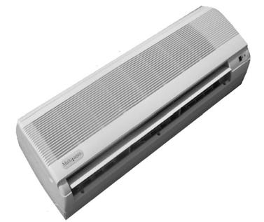
194 187
195 INSTALLATION & OPERATING MANUAL MHWW Hi-Wall Fan Coils 9,000-36,000 BTUH CAUTION Care must be taken when handling sheet metal. Sheet metal parts have sharp edges and could cause injury. GENERAL Read the entire contents of this manual before beginning installation. Multiaqua assumes no responsibility for equipment installed contradictory to any code requirement or installation instructions. The components of this fan coil have been inspected at the factory and readied for shipment. Upon receiving the shipment a visual inspection of the packaging must be performed. If any damage to the packaging is discovered, an inspection of the components must be performed and noted on the delivery documents. If component damage is found, a damage claim must be filed by the receiving party against the delivery party immediately. This product is designed and manufactured to permit installation in accordance with national codes. It is the installer s responsibility to install the product in accordance with national codes and/or prevailing local codes and regulations. Care must be taken to ensure the structural integrity of the supporting members, clearances and provisions for servicing, power supply, coil connections and/or condensate removal. Before the installation, ensure the structural strength of the supporting members is sufficient. See figure 1 for hanging weights of the fan coils. This unit is designed to be installed in a horizontal configuration only. See figure 2 for fan coil and mounting plate dimensions. FAN COIL APPROXIMATED MODEL NUMBER WEIGHTS (lbs) MHWW-09-H MHWW-12-H MHWW-18-H MHWW-24-H MHWW-36-H Figure 1 188
196 INSTALLATION & OPERATING MANUAL MHWW Hi-Wall Fan Coils 9,000-36,000 BTUH Fan Coil Model Number FAN COIL AND MOUNTING PLATE DIMENSIONS (in) A B C D E F G H I J K Field Supplied Hole L Field Supplied Hole MHWW MHWW MHWW MHWW MHWW A C D B Mounting Plate H G K E F L I J Figure 2 189
197 INSTALLATION & OPERATING MANUAL MHWW Hi-Wall Fan Coils 9,000 36,000 BTUH CAUTION Care must be taken when handling sheet metal. Sheet metal parts have sharp edges and could cause injury. INSTRUCTIONS FOR INSTALLING THE MOUNTING PLATE Figure 3 1. After a suitable place for installation has been selected, place the mounting plate horizontally on the wall. Make sure the alignment is horizontal. Use a plumb line if available. Mark on the wall where the mounting holes will be drilled. Figure 3 2. Drill the holes for the type of mounting hardware to be used. Check local building codes for correct mounting hardware. Secure the mounting plate and check for stiffness. Figure 4 3 Drill a diagonal piping access hole (2.75 ) in diameter on both sides of the mounting bracket. Refer to figure 2 for field supplied hole locations Figure 4 4. Check local and national codes for piping access wall penetrations. See figure 5 if wall sleeves are required. Figure 5 Figure 5 190
198 INSTALLATION & OPERATING MANUAL MHWW Hi-Wall Fan Coils 9,000 36,000 BTUH INSTRUCTIONS FOR INSTALLING FAN COIL UNIT ONTO MOUNTING PLATE 1. Route the fan coil piping, electrical, valve control wires and/or flexible drain hose through either of the 2.75 previously drilled holes in step 3 figure 4. Ensure that the piping is insulated per local and national codes. Improper insulation could result in voided warranty and/or building damage. Figure 6 Figure 6 2. There is a piping channel in the bottom portion of the back of the units for crossover piping, drain, valve control or electrical. Figure 7 Figure 7 3. Figure 8 depicts (from the back of the unit) the 24 vac valve control wires on the left and the 220 vac power cord on the right. These can be routed to either the right or left hand side of the fan coil. Figure 8 Figure 8 191
199 INSTALLATION & OPERATING MANUAL MHWW Hi-Wall Fan Coils 9,000 36,000 BTUH INSTRUCTIONS FOR INSTALLING FAN COIL UNIT ONTO MOUNTING PLATE 4. Ensure that the drain tubing is installed with at least 1/4 per foot of downward slope. 5. Secure the fan coil to the mounting plate by first sliding the fan coil onto the two notches provided on the mounting plate. Figure 9 & 10 Figure 9 6. Push the bottom of the fan coil towards the wall in order to engage the locking clips. Figure Connect the liquid solution piping flared fittings and pressure test lines to make sure there are no leaks. 8. Connect the condensate drain hose. Make certain that the drain has no traps or dips in the line that would impede drainage. Figure Carefully seal any wall penetrations per local and national codes. Figure

200 INSTALLATION & OPERATING MANUAL MHWW Hi-Wall Fan Coils 9,000 36,000 BTUH INSTRUCTIONS FOR REMOVING THE FAN COIL COVER AND AIR PURGING THE LIQUID SOLUTION COIL. 1. Fold up the filter cover and remove the three screw covers and screws that are located below the discharge air grille. Remove the one screw located between the two filter racks. Figure 12 Figure Grasp the bottom, sides of the cover and pull outward. Figure After fan coil and piping has been pressurized and the fan coil and piping has no indication of leaks, fill the system with liquid solution. 4. Energize the control valve to allow the coil to fill up with liquid solution. Figure Open the purging valve by using a standard screw driver and support fitting with a wrench. Ensure that any water that discharges from the purging valve does not come in contact with the electrical components. Figure When air purging is complete, close off the purging valve and check for leaks. Figure
201 INSTALLATION & OPERATING MANUAL MHWW Hi-Wall Fan Coils 9,000 36,000 BTUH MHWW CONTROLS OPERATION GUIDE Wireless Control: Standard Control Package (Page 195) Optional Wired Control: EG-003 (Page 200) 194
202 INSTALLATION & OPERATING MANUAL MHWW Hi-Wall Fan Coils 9,000 36,000 BTUH MHWW CONTROLS OPERATION GUIDE Wireless Control: Name and function of remote controller Note: Be sure there are no obstructions between receiver and remote controller. The remote control signal can be received at the distance of up to about 21 feet. Do not throw or drop the remote controller. Do not put any liquid in the remote controller and do not put it in direct sunlight or any place where it is very hot. Remove batteries when the remote controller is not in use for extended periods of time. The remote controller should be placed 3 or more feet away from any electric appliance. LED MODE INDICATOR FOR REMOTE CONTROLLER: INDICATOR LIGHTS REMOTE SETTING FUNCTION RED-GREEN COOL COOLING OPERATION ONLY RED-OFF DRY HUMIDITY CONTROL, WATER FLOW, NO FAN RED-RED HEAT HEATING OPERATION ONLY RED-OFF FAN FAN OPERATION ONLY RED-BLINKING AUTO AUTO SELECTION BETWEEN HEAT & COOL DEPENDENT ON ROOM TEMP & SET TEMP RED-ORANGE ALERT FAN COIL WAITING FOR EWT TO REACH PROPER TEMPERATURE NECESSARY TO SATISFY SET POINT 195
203 INSTALLATION & OPERATING MANUAL MHWW Hi-Wall Fan Coils 9,000 36,000 BTUH MHWW CONTROLS OPERATION GUIDE FUNCTION 1. TRANSMISSION SOURCE - Infra red transmission source 2. POWER - Press to turn the fan coil on and off or vice versa. (Red LED left will light to indicate the control is on) 3. MODE - To select desired operation mode. It will switch from one to another as shown. COOL - Cooling operation. DRY - Humidity control. HEAT - Heating operation. FAN - Fan only. No cooling or heating capability. AUTO - Operation mode will be selected automatically between HEAT and COOL mode, depending upon the room temperature and SET temperature. 4. FAN - To select fan speed. It will switch from one to another as shown below. - When the system temperature sensor is not calling for cool or heat the fan will run at the speed previously entered in fan mode selection (high, medium or low). - If auto was the previously entered fan speed in cooling: The fan will run at low speed until the temperature sensor calls for either heating or cooling at which point the fan will return to auto speed control Fan speed sequence 196
204 INSTALLATION & OPERATING MANUAL MHWW Hi-Wall Fan Coils 9,000 36,000 BTUH MHWW CONTROLS OPERATION GUIDE FUNCTION 5. TEMPERATURE SETTING - Press to increase set temperature. - Press to decrease set temperature. - Press and Simultaneously to toggle between C and F display mode. - Temperature range: 16 C to 30 C in C display mode and 60 F to 86 F in F display mode. 6. DELAY TIMER SETTING - The delay timer is capable of delaying both on and off functions. The delay feature will take affect in all modes with the exception of the sleep mode. Each time the and is pressed it increases or decreases the On or OFF set point by 1 hour; up to a maximum of 18 hours. To set the OFF DELAY: -With the system in operation, enter the system OFF time by pressing the button to the desired number of hours ahead that the system will be allowed to run. When the number of hours entered has elapsed the system will turn off. To set the ON DELAY: - Set the on delay by entering the desired mode of operation (fan, heat, cool and the appropriate temperature. This will be the settings the system will follow when operation resumes. After setting the mode and any applicable temperature with the control, turn the remote off. Now enter the number of hours to elapse before operation resumes by pressing the button on the remote to the desired number. When the time (in hours) entered has elapsed, the system will resume operation according to the pre-set mode and temperature. 197
205 INSTALLATION & OPERATING MANUAL MHWW Hi-Wall Fan Coils 9,000 36,000 BTUH MHWW CONTROLS OPERATION GUIDE 7. CANCEL - To cancel any setting on the delay timer. 8. LOUVER - Two different functions are available: 1. To set the louver stop position. There are 4 angles available. The sequence is as follows. 2. To set the louver swing (continuous motion). The sequence is as follows. 9. SLEEP - This function when selected will allow the user to determine a sleep period. In cooling the selected temperature will rise to 1 above set point in 1/2 hour, rising to 2 in 1 hour, rising again to 4 after 2 hours of the SLEEP CYCLE. SLEEP FUNCTION DISPLAY 10. DRY - This function operates to control humidity within a conditioned space. It measures the difference between set point and the actual room temperature. An algorithm determines how far above set point the actual room temperature is to set point temperature and selects periods of water valve operation and low fan operation. The greater the difference between room temperature and set point temperature prompts greater run time with less temperature. With less temperature differences, periods of fan and valve operation are called for in varying increments as determined by the difference. In this mode (low speed) fan operation will start 30 seconds after valve has opened and stops 30 seconds after valve has closed. 198
206 INSTALLATION & OPERATING MANUAL MHWW Hi-Wall Fan Coils 9,000 36,000 BTUH MHWW CONTROLS OPERATION GUIDE 11. AUTO - This function will automatically control the system switching between heating and cooling operation. If the preset auto mode is cooling, a switch to heating operation will begin only if the actual room temperature is 7 below selected control set point. If the present auto mode is heating, a switch to cooling operation will begin only when the room temperature is 3 above selected control set point. 12. TRANSMISSION INDICATOR - Blinks twice to indicate that transmission has taken place between remote and receiver. - Beeps indicate fan coil acknowledging receipt of transmission. TRANSMISSION INDICATOR 13. HOW TO INSERT BATTERIES 1. Remove the battery cover from the back of the remote. 2. Insert the (2) AAA batteries. Ensure that the polarity of the batteries are as shown inside of the battery compartment. 3. Re-attach the battery compartment cover. 199
207 INSTALLATION & OPERATING MANUAL MHWW Hi-Wall Fan Coils 9,000 36,000 BTUH MHWW CONTROLS OPERATION GUIDE Optional Wired Control: EG-003 LED MODE INDICATOR FOR REMOTE CONTROLLER: INDICATOR LIGHTS SETTING FUNCTION RED-GREEN COOL COOLING OPERATION ONLY RED-RED HEAT HEATING OPERATION ONLY RED-BLINKING AUTO AUTO SELECTION BETWEEN HEAT & COOL RED-OFF FAN FAN OPERATION ONLY 1. POWER - Press to turn the fan coil on and off or vice versa. 2. MODE - To select desired operation mode. It will switch from one to another as shown. COOL - Cooling operation. HEAT - Heating operation. FAN - Fan only. No cooling or heating capability. AUTO - Operation mode will be selected automatically between HEAT and COOL mode depending upon the room temperature and SET temperature. 3. FAN - To select fan speed. It will switch from one to another as shown below. - When the system temperature sensor is not calling for cool or heat the fan will run at the speed previously entered in fan mode selection (high, medium or low). - If auto was the previously entered fan speed in cooling: The fan will run at low speed until the temperature sensor calls for either heating or cooling at this point the fan will return to auto speed control Fan Speed Sequence 200
208 INSTALLATION & OPERATING MANUAL MHWW Hi-Wall Fan Coils 9,000 36,000 BTUH MHWW CONTROLS OPERATION GUIDE FUNCTION 4. TEMPERATURE SETTING - Press to increase set temperature. - Press to decrease set temperature. - Press and Simultaneously to toggle between C and F display mode. - Temperature range: 16 C to 30 C in C display mode and 60 F to 86 F in F display mode. 5. CANCEL - To cancel any setting on the delay timer. 6. LOUVER - Two different functions are available: 1. To set the louver stop position. There are 4 angles available. The sequence is as follows. 2. To set the louver swing (continuous motion). The sequence is as follows. 7. AUTO - This function will automatically control the system switching between heating and cooling operation. If the present auto mode is cooling, a switch to heating operation will begin only if the actual room temperature is 7 below selected control set point. If the present auto mode is heating, a switch to cooling operation will begin only when the room temperature is 3 above selected control set point. 201
209 MHWW-09-H-1 & MHWW-12-H-1 Wiring Diagram 208/230/-1-50/60 202
210 MHWW-18-H-1 Wiring Diagram 208/230/-1-50/60 203
211 MHWW-24-H-1 Wiring Diagram 208/230/-1-50/60 204
212 MHWW-36-H-1 Wiring Diagram 208/230/-1-50/60 205
213 MHWW CERTIFIED DRAWING 206
214 CFFWA Chilled/Hot Water Universal Mount Fan Coil 2-Pipe Heat / Cool Fan Coil 12,000-60,000 BTUH 207
215 CFFWA NOMENCLATURE BREAKDOWN 2-Pipe Heat/Cool Universal Mount Fan Coil CFFWA- XX U 2-Pipe Heat/Cool Control Option 24 vac Ready Voltage 1=208/230/-1-50/60 Nominal CFM 04=400 06=600 08=800 12= = =2000 Available Model Numbers CFFWA-04-1-U CFFWA-06-1-U CFFWA-08-1-U CFFWA-12-1-U CFFWA-16-1-U CFFWA-20-1-U 208
216 HVAC Guide Specifications Chilled and Hot Water Universal Mount Fan Coil 2-Pipe Nominal Size: 12,000 60,000 BTUH Multiaqua Model Number: CFFWA-04-1-U CFFWA-06-1-U CFFWA-08-1-U CFFWA-12-1-U CFFWA-16-1-U CFFWA-20-1-U Part 1-General 1.01 System Description Multiaqua Chilled Water Fan Coils are manufactured with galvanized steel and high impact molded polymers Quality Assurance A. Certified in accordance with U.L. Standard 95, latest version (U.S.A.) B. Manufactured in a facility registered to ISO 9002, Manufacturing Quality Standard. C. Fully load tested at the factory. D. Damage resistant packaging Delivery, Storage and Handling A. Packaged and readied for shipment from the factory. B. Controls shall be capable of withstanding 150 F storage temperatures in the control compartment. C. Stored and handled per manufacturer s recommendations. Part 2-Product 2.01 Equipment A. General: 1. Unit shall be a factory assembled and tested chilled and hot water fan coil. 2. Shall be assembled with high quality. 3. Contained with the unit shall be all factory wiring, piping, associated controls and special accessories required prior to start up. B. Unit Cabinet: 1. Composed of high impact polymers. 2. Shall be internally insulated to insure quiet operation. C. Fan Motors: 1. Shall be available in 208/ /60 vac. 1. Fan motors shall be three speed, direct drive, and PSC type. 2. Totally enclosed. 3. Internal overload protected. 4. Unit shall contain a swing motor to modulate the discharge air. D. Blower Wheels: 1. Blower wheels are tangential and dynamically balanced. E. Water Coil: 1. Manufactured with water coils containing 3/8 copper tubing mechanically bonded to aluminum fins. 2. Coils shall be factory tested to 350 psig. F. Drain Pan: 1. All drain pans shall be coated on both the interior and exterior with baked polyester powder to resist corrosion. 2. The exterior of all drain pans shall be insulated with closed cell to prevent condensation. 3. Pans shall contain a drain tubing that is accessible from the back, bottom and side of the unit. 209
217 G. Filters: 1. Unit shall contain 65% washable filters. Part 3-Controls and Safeties 3.01 Controls A. Fan coils shall be completely factory wired and tested. B. Unit shall include a terminal block that is capable of incorporating a 24 vac thermostat. C. Controls shall be capable of incorporating an optional hard-wired thermostat Safeties: A. Fan coil shall contain a non reusable fuse on the secondary voltage side of the transformer. Part 4-Operating Characteristics: 4.01 Electrical Requirements A. Electrical shall include a terminal block. B. Electrical power supply shall be rated to withstand 120 F operating ambient temperatures. 210
218 CFFWA Product Specifications Model Number Height (in) Length (in) Physical Data Depth (in) Weight (lbs) Cooling Rows FPI Water Inlet (in) Water Outlet (in) CFFWA-04-1-U /2 1/2 1/2 CFFWA-06-1-U /2 1/2 1/2 CFFWA-08-1-U /2 1/2 1/2 CFFWA-12-1-U /4 3/4 1/2 CFFWA-16-1-U /4 3/4 1/2 CFFWA-20-1-U /2 Drain (in) Electrical Data Model Number CFM Volts/ Phase/ Hertz Motor HP Full Load Ampacity Fuse or HACR Circuit Breaker Per Circuit Minimum Amps Maximum Amps CFFWA-04-1-U 436 1/ CFFWA-06-1-U 520 1/ CFFWA-08-1-U 650 1/ CFFWA-12-1-U 735 CFFWA-16-1-U 1360 CFFWA-20-1-U / /60 1/8 & 1/20 1/8 & 1/8 1/8 & 1/ These specifications are subject to change without notice. 211
219 CFFWA Chilled Water Performance Data CFM CFFWA-04 COOLING CAPACITIES EWT GPM ENTERING AIR TEMPERATURE (F) ( F) 80 D.B. / 67 W.B. 75 D.B. / 63 W.B TC SC WPD TC SC WPD TC SC WPD TC SC WPD CFM CFFWA-04 COOLING CAPACITIES EWT GPM ENTERING AIR TEMPERATURE (F) ( F) 80 D.B. / 67 W.B. 75 D.B. / 63 W.B TC SC WPD TC SC WPD TC SC WPD TC SC WPD These specifications are subject to change without notice. 212
220 CFFWA Chilled Water Performance Data CFM CFFWA-06 COOLING CAPACITIES EWT GPM ENTERING AIR TEMPERATURE (F) ( F) 80 D.B. / 67 W.B. 75 D.B. / 63 W.B TC SC WPD TC SC WPD TC SC WPD TC SC WPD CFM CFFWA-06 COOLING CAPACITIES EWT GPM ENTERING AIR TEMPERATURE (F) ( F) 80 D.B. / 67 W.B. 75 D.B. / 63 W.B TC SC WPD TC SC WPD TC SC WPD TC SC WPD These specifications are subject to change without notice. 213
221 CFFWA Chilled Water Performance Data CFM CFFWA-08 COOLING CAPACITIES EWT GPM ENTERING AIR TEMPERATURE (F) ( F) 80 D.B. / 67 W.B. 75 D.B. / 63 W.B TC SC WPD TC SC WPD TC SC WPD TC SC WPD CFM CFFWA-08 COOLING CAPACITIES EWT GPM ENTERING AIR TEMPERATURE (F) ( F) 80 D.B. / 67 W.B. 75 D.B. / 63 W.B TC SC WPD TC SC WPD TC SC WPD TC SC WPD These specifications are subject to change without notice. 214
222 CFFWA Chilled Water Performance Data CFM CFFWA-12 COOLING CAPACITIES EWT GPM ENTERING AIR TEMPERATURE (F) ( F) 80 D.B. / 67 W.B. 75 D.B. / 63 W.B TC SC WPD TC SC WPD TC SC WPD TC SC WPD CFM CFFWA-12 COOLING CAPACITIES EWT GPM ENTERING AIR TEMPERATURE (F) ( F) 80 D.B. / 67 W.B. 75 D.B. / 63 W.B TC SC WPD TC SC WPD TC SC WPD TC SC WPD These specifications are subject to change without notice. 215
223 CFFWA Chilled Water Performance Data CFM CFFWA-16 COOLING CAPACITIES EWT GPM ENTERING AIR TEMPERATURE (F) ( F) 80 D.B. / 67 W.B. 75 D.B. / 63 W.B TC SC WPD TC SC WPD TC SC WPD TC SC WPD CFM CFFWA-16 COOLING CAPACITIES EWT GPM ENTERING AIR TEMPERATURE (F) ( F) 80 D.B. / 67 W.B. 75 D.B. / 63 W.B TC SC WPD TC SC WPD TC SC WPD TC SC WPD These specifications are subject to change without notice. 216
224 CFFWA Chilled Water Performance Data CFM CFFWA-20 COOLING CAPACITIES EWT GPM ENTERING AIR TEMPERATURE (F) ( F) 80 D.B. / 67 W.B. 75 D.B. / 63 W.B TC SC WPD TC SC WPD TC SC WPD TC SC WPD CFM CFFWA-20 COOLING CAPACITIES EWT GPM ENTERING AIR TEMPERATURE (F) ( F) 80 D.B. / 67 W.B. 75 D.B. / 63 W.B TC SC WPD TC SC WPD TC SC WPD TC SC WPD These specifications are subject to change without notice. 217
225 CFFWA Hot Water Performance Data CFFWA-04 HEATING CAPACITIES ENTERING ENTERING WATER TEMPERATURE ( F) CFM GPM WPD AIR ( F) CFFWA-04 HEATING CAPACITIES ENTERING ENTERING WATER TEMPERATURE ( F) CFM GPM WPD AIR ( F) CFFWA-04 HEATING CAPACITIES ENTERING ENTERING WATER TEMPERATURE ( F) CFM GPM WPD AIR ( F) CFFWA-04 HEATING CAPACITIES ENTERING ENTERING WATER TEMPERATURE ( F) CFM GPM WPD AIR ( F) These specifications are subject to change without notice. 218
226 CFFWA Hot Water Performance Data CFFWA-06 HEATING CAPACITIES ENTERING ENTERING WATER TEMPERATURE ( F) CFM GPM WPD AIR ( F) CFFWA-06 HEATING CAPACITIES ENTERING ENTERING WATER TEMPERATURE ( F) CFM GPM WPD AIR ( F) CFFWA-06 HEATING CAPACITIES ENTERING ENTERING WATER TEMPERATURE ( F) CFM GPM WPD AIR ( F) CFFWA-06 HEATING CAPACITIES ENTERING ENTERING WATER TEMPERATURE ( F) CFM GPM WPD AIR ( F) These specifications are subject to change without notice. 219
227 CFFWA Hot Water Performance Data CFFWA-08 HEATING CAPACITIES ENTERING ENTERING WATER TEMPERATURE ( F) CFM GPM WPD AIR ( F) CFFWA-08 HEATING CAPACITIES ENTERING ENTERING WATER TEMPERATURE ( F) CFM GPM WPD AIR ( F) CFFWA-08 HEATING CAPACITIES ENTERING ENTERING WATER TEMPERATURE ( F) CFM GPM WPD AIR ( F) CFFWA-08 HEATING CAPACITIES ENTERING ENTERING WATER TEMPERATURE ( F) CFM GPM WPD AIR ( F) These specifications are subject to change without notice. 220
228 CFFWA Hot Water Performance Data CFFWA-12 HEATING CAPACITIES ENTERING ENTERING WATER TEMPERATURE ( F) CFM GPM WPD AIR ( F) CFFWA-12 HEATING CAPACITIES ENTERING ENTERING WATER TEMPERATURE ( F) CFM GPM WPD AIR ( F) CFFWA-12 HEATING CAPACITIES ENTERING ENTERING WATER TEMPERATURE ( F) CFM GPM WPD AIR ( F) CFFWA-12 HEATING CAPACITIES ENTERING ENTERING WATER TEMPERATURE ( F) CFM GPM WPD AIR ( F) These specifications are subject to change without notice. 221
229 CFFWA Hot Water Performance Data CFFWA-16 HEATING CAPACITIES ENTERING ENTERING WATER TEMPERATURE ( F) CFM GPM WPD AIR ( F) CFFWA-16 HEATING CAPACITIES ENTERING ENTERING WATER TEMPERATURE ( F) CFM GPM WPD AIR ( F) CFFWA-16 HEATING CAPACITIES ENTERING ENTERING WATER TEMPERATURE ( F) CFM GPM WPD AIR ( F) CFFWA-16 HEATING CAPACITIES ENTERING ENTERING WATER TEMPERATURE ( F) CFM GPM WPD AIR ( F) These specifications are subject to change without notice. 222
230 CFFWA Hot Water Performance Data CFFWA-20 HEATING CAPACITIES ENTERING ENTERING WATER TEMPERATURE ( F) CFM GPM WPD AIR ( F) CFFWA-20 HEATING CAPACITIES ENTERING ENTERING WATER TEMPERATURE ( F) CFM GPM WPD AIR ( F) CFFWA-20 HEATING CAPACITIES ENTERING ENTERING WATER TEMPERATURE ( F) CFM GPM WPD AIR ( F) CFFWA-20 HEATING CAPACITIES ENTERING ENTERING WATER TEMPERATURE ( F) CFM GPM WPD AIR ( F) These specifications are subject to change without notice. 223
231 223
232 CFFWA CFM and Glycol Adjustments CAPACITY CORRECTION FACTORS MODEL # CFFWA-04 CFFWA-06 CFFWA-08 CFFWA-12 CFFWA-16 CFFWA-20 CFM TC SC TC SC TC SC TC SC TC SC TC SC Propylene Glycol & GPM Adjustment Factors Propylene Glycol % Capacity Reduction GPM Adjustment = 100% Capacity Ambient Temp 26 F 10% x 0.99 x F 20% x 0.98 x F 30% x 0.98 x F 40% x 0.97 x F 50% x 0.96 x 1.16 Example: 30% Propylene Glycol Solution. System capacity x 0.98 GPM x 1.07 These specifications are subject to change without notice 224

233 225
234 INSTALLATION & OPERATING MANUAL CFFWA Universal Mount Fan Coils 12,000-60,000 BTUH CAUTION Care must be taken when handling sheet metal. Sheet metal parts have sharp edges and could cause injury. GENERAL Read the entire contents of this manual before beginning installation. Multiaqua assumes no responsibility for equipment installed contradictory to any code requirement or installation instructions. The components of this fan coil have been inspected at the factory and readied for shipment. Upon receiving the shipment a visual inspection of the packaging must be performed. If any damage to the packaging is discovered, an inspection of the components must be performed and noted on the delivery documents. If component damage is found a damage claim must be filed by the receiving party against the delivery party immediately. This product is designed and manufactured to permit installation in accordance with national codes. It is the installer s responsibility to install the product in accordance with national codes and/or prevailing local codes and regulations. Care must be taken to ensure the structural integrity of the supporting members, clearances and provisions for servicing, power supply, coil connections and/or condensate removal. Before the installation ensure the structural strength of the supporting members is sufficient. See figure 1 for hanging weights of the fan coils. This unit is designed to be installed in a horizontal or vertical configuration. Fan coil can be mounted on a wall or ceiling. See figure 2 for fan coil and mounting bracket dimensions. FAN COIL APPROXIMATED MODEL NUMBER WEIGHTS (lbs) CFFWA-04-1-U CFFWA-06-1-U CFFWA-08-1-U CFFWA-12-1-U CFFWA-16-1-U CFFWA-20-1-U Figure 1 226
235 INSTALLATION & OPERATING MANUAL CFFWA Universal Mount Fan Coil 12,000-60,000 BTUH CFFWA Mounting Bracket Dimensions (in) Model Number A B CFFWA-04-1-U CFFWA-06-1-U CFFWA-08-1-U CFFWA-12-1-U CFFWA-16-1-U CFFWA-20-1-U A BACK B typ Figure 2 227
236 INSTALLATION & OPERATING MANUAL CFFWA Universal Mount Fan Coils 12,000 60,000 BTUH CAUTION Care must be taken when handling sheet metal. Sheet metal parts have sharp edges and could cause injury. INSTRUCTIONS FOR INSTALLING THE MOUNTING BRACKETS AND UNIT 1. The unit should be installed for horizontal and vertical discharge applications only. Figure 3 2. Select position for unit and define direction of water pipe, drain and electrical wiring. Access to the above can be obtained from the right hand side bottom, back and side. See page 229 for access dimensions. Figure 3, 4 and 5 3. Remove mounting brackets from both sides of unit. Figure 4 Figure 6 4. Prepare mounting bolts for mounting unit under ceiling or on a wall at the distance provided in figure Select a location that permits even air flow throughout the room. 6. Select a location that has enough service space when the unit is mounted under the ceiling or on the wall Figure 5 228
237 INSTALLATION & OPERATING MANUAL CFFWA Universal Mount Fan Coils 12,000 60,000 BTUH Piping Locations 229
238 INSTALLATION & OPERATING MANUAL CFFWA Universal Mount Fan Coils 12,000 60,000 BTUH CAUTION Care must be taken when handling sheet metal. Sheet metal parts have sharp edges and could cause injury. INSTRUCTIONS FOR INSTALLING THE MOUNTING BRACKETS AND UNIT 7. Carefully place fan coil into place and align mounting holes in fan coil to the holes in the mounting bracket. Typical both sides. Figure 6 Figure 6 8. Connections to the indoor unit are flared connections for both the inlet and outlet to the fan coil. Figure 7 9. Ensure tubing and fittings are in line with another before tightening nut to allow concentric seating of tube onto flare nut as to prevent leakage. Figure Insulate both the inlet and outlet liquid solution lines to prevent condensation leakage. 11. Connect the field drain line to the clear drain tubing provided on the drain pan of the fan coil. Ensure the drain line has a ¼ of fall per foot. Insulate the condensate drain line to prevent sweating. Figure 8 230
239 CFFWA-xx-1-U Wiring Diagram 208/230/-1-50/60 231
240 CFFWA CERTIFIED DRAWING 232


241 CWA2 Chilled Water Fan Coil With or Without Electric Heat 2-Pipe Heat / Cool Fan Coil 18,000-60,000 BTUH 233
242 CWA2 NOMENCLATURE BREAKDOWN 2-Pipe Heat/Cool with Electric Heat Multiposition Fan Coil Nominal BTUH xx- CWA2- xx KW Electric Heat 00 = 0KW 18 = 18, = 5KW 24 = 24, = 8KW 36 = 36, = 10KW 48 = 48, = 15KW 60 = 60, = 20KW 2-Pipe Heat/Cool W/ Electric Heat Note: The CWA2 is only available in 208/ Available Model Numbers 18CWA CWA CWA CWA CWA CWA CWA CWA CWA CWA CWA CWA CWA CWA CWA CWA CWA CWA CWA CWA CWA CWA CWA CWA CWA
243 HVAC Guide Specifications Chilled/ Hot Water W/Electric Heat Multi-Position Fan Coil 2-Pipe Nominal Size: 18,000 60,000 BTUH Multiaqua Model Number: 18CWA2 24CWA2 36CWA2 48CWA2 60CWA2 Part 1-General 1.01 System Description Multiaqua Chilled Water Fan Coils are manufactured with heavy gauge galvanized steel to resist corrosion Quality Assurance A. Certified in accordance with U.L. Standard 95, latest version (U.S.A.) B. Manufactured in a facility registered to ISO 9002, Manufacturing Quality Standard. C. Fully load tested at the factory. D. Damage resistant packaging Delivery, Storage and Handling A. Packaged and readied for shipment from the factory. B. Controls shall be capable of withstanding 150 F storage temperatures in the control compartment. C. Stored and handled per manufacturer s recommendations. Part 2-Product 2.01 Equipment A. General: 1. Unit shall be a factory assembled and tested multi-position chilled/ hot water with electric heat fan coil. 2. Shall be assembled with high quality. 3. Contained with the unit shall be all factory wiring, piping, associated controls and special accessories required prior to start up. B. Unit Cabinet: 1. Composed of heavy gauge galvanized steel casing with baked polyester powder. 2. Shall be internally insulated to insure quiet operation. 3. Cabinet shall be capable of being installed in a vertical or horizontal position. C. Fan Motors: 1. Shall be available in 208/ vac. 1. Fan motors shall be three speed, direct drive, and PSC type. 2. Internal overload protected. D. Blower Wheels: 1. Blower wheels are forward curved and dynamically balanced. E. Water Coil: 1. Manufactured with water coils containing 3/8 copper tubing mechanically bonded to aluminum fins. 2. Coils shall be factory tested to 350 psig. 3. Coil shall contain manual air bleed port. F. Drain Pan: 1. Drain pan shall be molded with high impact polymers. 2. Pan shall contain a primary and secondary drain connection. 3. Pan shall be capable of draining in the vertical and horizontal positions without changing the pan configuration. 235
244 G. Filters: 1. Unit shall contain a filter door for easy access to the filter. 2. A filter track shall be provided. 3. Unit shall come supplied with a 1 throwaway filter. H. Electric Heaters: 1. Unit shall be capable of incorporating an electric heat package. 2. Electric heaters shall be of the open wire type. 3. Electric heat packages shall contain non-fused breakers, sequencers and safeties. Part 3-Controls and Safeties 3.01 Controls A. Fan coils shall be completely factory wired and tested. B. Unit shall include a terminal block that is capable of incorporating a 24 vac thermostat Safeties: A. Fan coil shall contain a non reusable fuse on the secondary voltage side of the transformer. B. Electric heat package shall contain non-fusible breakers and high temperature limits. Part 4-Operating Characteristics: 4.01 Electrical Requirements A. Electrical shall include a terminal block. B. Electrical power supply shall be rated to withstand 120 F operating ambient temperatures. 236
245 Model Number Height (in) CWA2 Product Specifications Length (in) Depth (in) Physical Data Weight (lbs) 237 Cooling Rows FPI Copper Diameter (in) Water Inlet (in) Water Outlet (in) 18CWA /8 1/2 1/2 3/4 24CWA /8 1/2 1/2 3/4 36CWA /8 3/4 3/4 3/4 48CWA /8 3/4 3/4 3/4 60CWA /8 3/4 3/4 3/4 Electrical Data Model Number Model Number Nominal CFM Nominal CFM 18CWA2-XX CWA2-XX CWA2-XX CWA2-XX CWA2-XX 2000 Volts/ Phase/ Hertz Motor HP KW Electric Heat Full Load Ampacity Minimum Ampacity Maximum Breaker 240V 208V 240V 208V 240V 208V /26 49/23 60/30 50/ /30 46/27 60/30 50/ /53 50/46 60/60 50/ /32 46/29 60/35 50/ /53 52/46 60/60 60/50 These specifications are subject to change without notice. Fuse or HACR Circuit Breaker Per Circuit Minimum Amps Maximum Amps 18CWA / CWA / CWA / CWA / CWA / / Drain (in)
246 CWA2 Chilled Water Performance Data NOMINAL CFM 18CWA2-XX COOLING CAPACITIES EWT ( F) GPM WPD ENTERING AIR TEMPERATURE 80 D.B. / 67 W.B. TC 12.2 SC 9.2 APD 0.1 TC 13.4 SC 10.1 APD 0.1 TC 14.2 SC 10.6 APD 0.1 NOMINAL CFM 18CWA2-XX COOLING CAPACITIES EWT ( F) GPM WPD ENTERING AIR TEMPERATURE 80 D.B. / 67 W.B. TC 16.6 SC 12.5 APD 0.18 TC 18.1 SC 13.6 APD 0.18 TC 19.1 SC 14.4 APD 0.18 NOMINAL CFM 18CWA2-XX COOLING CAPACITIES EWT ( F) GPM WPD ENTERING AIR TEMPERATURE 80 D.B. / 67 W.B. TC 11.5 SC 9.2 APD 0.1 TC 12.5 SC 10.0 APD 0.1 TC 13.2 SC 10.5 APD 0.1 NOMINAL CFM 18CWA2-XX COOLING CAPACITIES EWT ( F) GPM WPD ENTERING AIR TEMPERATURE 80 D.B. / 67 W.B. TC 15.7 SC 12.6 APD 0.18 TC 17.0 SC 13.6 APD 0.18 TC 17.9 SC 14.3 APD 0.18 These specifications are subject to change without notice. 238
247 CWA2 Chilled Water Performance Data NOMINAL CFM 24CWA2-XX COOLING CAPACITIES EWT ( F) GPM WPD ENTERING AIR TEMPERATURE 80 D.B. / 67 W.B. TC 16.5 SC 12.4 APD 0.14 TC 18.4 SC 13.8 APD 0.14 TC 19.7 SC 14.7 APD 0.14 NOMINAL CFM 24CWA2-XX COOLING CAPACITIES EWT ( F) GPM WPD ENTERING AIR TEMPERATURE 80 D.B. / 67 W.B. TC 20.9 SC 15.7 APD 0.21 TC 22.9 SC 17.2 APD 0.21 TC 24.4 SC 18.3 APD 0.21 NOMINAL CFM 24CWA2-XX COOLING CAPACITIES EWT ( F) GPM WPD ENTERING AIR TEMPERATURE 80 D.B. / 67 W.B. TC 15.7 SC 12.7 APD 0.14 TC 17.3 SC 13.8 APD 0.14 TC 18.3 SC 14.6 APD 0.14 NOMINAL CFM 24CWA2-XX COOLING CAPACITIES EWT ( F) GPM WPD ENTERING AIR TEMPERATURE 80 D.B. / 67 W.B. TC 19.8 SC 15.8 APD 0.21 TC 21.6 SC 17.3 APD 0.21 TC 22.9 SC 18.3 APD 0.21 These specifications are subject to change without notice. 239
248 CWA2 Chilled Water Performance Data NOMINAL CFM 36CWA2-XX COOLING CAPACITIES EWT ( F) GPM WPD ENTERING AIR TEMPERATURE 80 D.B. / 67 W.B. TC 26.0 SC 19.5 APD 0.2 TC 29.0 SC 21.8 APD 0.2 TC 31.0 SC 23.2 APD 0.2 NOMINAL CFM 36CWA2-XX COOLING CAPACITIES EWT ( F) GPM WPD ENTERING AIR TEMPERATURE 80 D.B. / 67 W.B. TC 31.2 SC 23.3 APD 0.3 TC 33.3 SC 25.0 APD 0.3 TC 35.0 SC 26.3 APD 0.3 NOMINAL CFM 36CWA2-XX COOLING CAPACITIES EWT ( F) GPM WPD ENTERING AIR TEMPERATURE 80 D.B. / 67 W.B. TC 24.8 SC 19.8 APD 0.23 TC 27.3 SC 21.8 APD 0.23 TC 29.0 SC 23.2 APD 0.23 NOMINAL CFM 36CWA2-XX COOLING CAPACITIES EWT ( F) GPM WPD ENTERING AIR TEMPERATURE 80 D.B. / 67 W.B. TC 29.6 SC 23.7 APD 0.28 TC 31.5 SC 25.2 APD 0.28 TC 31.9 SC 25.5 APD 0.28 These specifications are subject to change without notice. 240
249 CWA2 Chilled Water Performance Data NOMINAL CFM 48CWA2-XX COOLING CAPACITIES EWT ( F) GPM WPD ENTERING AIR TEMPERATURE 80 D.B. / 67 W.B. TC 33.4 SC 25.0 APD 0.24 TC 36.3 SC 27.2 APD 0.24 TC 38.5 SC 28.9 APD 0.24 NOMINAL CFM 48CWA2-XX COOLING CAPACITIES EWT ( F) GPM WPD ENTERING AIR TEMPERATURE 80 D.B. / 67 W.B. TC 39.5 SC 29.6 APD 0.25 TC 42.7 SC 32.0 APD 0.25 TC 45.1 SC 33.8 APD 0.25 NOMINAL CFM 48CWA2-XX COOLING CAPACITIES EWT ( F) GPM WPD ENTERING AIR TEMPERATURE 80 D.B. / 67 W.B. TC 32.0 SC 25.6 APD 0.24 TC 34.5 SC 27.6 APD 0.24 TC 36.4 SC 29.1 APD 0.24 NOMINAL CFM 48CWA2-XX COOLING CAPACITIES EWT ( F) GPM WPD ENTERING AIR TEMPERATURE 80 D.B. / 67 W.B. TC 37.7 SC 30.2 APD 0.25 TC 40.5 SC 32.4 APD 0.25 TC 42.6 SC 34.1 APD 0.25 These specifications are subject to change without notice. 241
250 CWA2 Chilled Water Performance Data NOMINAL CFM 60CWA2-XX COOLING CAPACITIES EWT ( F) GPM WPD ENTERING AIR TEMPERATURE 80 D.B. / 67 W.B. TC 42.5 SC 31.9 APD 0.19 TC 45.6 SC 34.2 APD 0.19 TC 48.1 SC 36.1 APD 0.19 NOMINAL CFM 60CWA2-XX COOLING CAPACITIES EWT ( F) GPM WPD ENTERING AIR TEMPERATURE 80 D.B. / 67 W.B. TC 50.0 SC 37.5 APD 0.27 TC 55.1 SC 41.3 APD 0.27 TC 58.7 SC 44.0 APD 0.27 NOMINAL CFM 60CWA2-XX COOLING CAPACITIES EWT ( F) GPM WPD ENTERING AIR TEMPERATURE 80 D.B. / 67 W.B. TC 40.4 SC 32.3 APD 0.19 TC 43.1 SC 34.5 APD 0.19 TC 45.2 SC 36.2 APD 0.19 NOMINAL CFM 60CWA2-XX COOLING CAPACITIES EWT ( F) GPM WPD ENTERING AIR TEMPERATURE 80 D.B. / 67 W.B. TC 47.7 SC 36.2 APD 0.27 TC 52.1 SC 41.7 APD 0.27 TC 55.2 SC 44.2 APD 0.27 These specifications are subject to change without notice. 242
251 CWA2 Hot Water Performance Data ENTERING AIR ( F) ENTERING AIR ( F) ENTERING AIR ( F) ENTERING AIR ( F) CWA2-00 HEATING CAPACITIES CFM GPM WPD APD CWA2-00 HEATING CAPACITIES CFM GPM WPD APD CWA2-00 HEATING CAPACITIES CFM GPM WPD APD CWA2-00 HEATING CAPACITIES CFM GPM WPD APD These specifications are subject to change without notice. 243
252 CWA2 Hot Water Performance Data ENTERING AIR ( F) ENTERING AIR ( F) ENTERING AIR ( F) ENTERING AIR ( F) CFM GPM WPD APD 36CWA2-00 HEATING CAPACITIES CFM GPM WPD APD 36CWA2-00 HEATING CAPACITIES CFM GPM WPD APD 48CWA2-00 HEATING CAPACITIES CFM GPM WPD APD 48CWA2-00 HEATING CAPACITIES These specifications are subject to change without notice. 244
253 CWA2 Hot Water Performance Data ENTERING AIR ( F) ENTERING AIR ( F) CFM GPM WPD APD 60CWA2-00 HEATING CAPACITIES CFM GPM WPD APD 60CWA2-00 HEATING CAPACITIES These specifications are subject to change without notice. 245
254 CWA2 CFM and Glycol Adjustments Model Motor CFM vs. ESP Number Speed High CWA-XX Medium Low High CWA-XX Medium Low High CWA-XX Medium Low High CWA-XX Medium Low High CWA-XX Medium Low Example: 0.20 ESP produces 900 cfm. Locate 900 cfm (for the 24CWA2) on the Capacity Adjustment Factors on page 247. (TC =1.05 & SC = 1.05) Multiply the stated chilled water capacity for the 24CWA2 on page 239 or the hot water capacity on page 243 by the adjustment factors to achieve the capacity adjustment. Propylene Glycol & GPM Adjustment Factors Propylene Glycol % Capacity Reduction GPM Adjustment = 100% Capacity Ambient Temp 26 F 10% x 0.99 x F 20% x 0.98 x F 30% x 0.98 x F 40% x 0.97 x F 50% x 0.96 x 1.16 Example: 30% Propylene Glycol Solution. System capacity x 0.98 GPM x 1.07 These specifications are subject to change without notice. 246
255 CWA2 Capacity Adjustment Factors CWA2 CAPACITY CORRECTION FACTORS MODEL # 18CWA2 24CWA2 36CWA2 CFM TC SC TC SC TC SC These specifications are subject to change without notice. 247
256 CWA2 Capacity Adjustment Factors CWA2 CAPACITY CORRECTION FACTORS MODEL # 48CWA2 60CWA2 CFM TC SC TC SC These specifications are subject to change without notice. 248
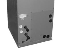
257 249
258 INSTALLATION & OPERATING MANUAL CWA2 Chilled Water Fan Coil with Electric Heat 18,000 60,000 BTUH CAUTION Care must be taken when handling sheet metal. Sheet metal parts have sharp edges and could cause injury. GENERAL Read the entire contents of this manual before beginning installation. Multiaqua assumes no responsibility for equipment installed contradictory to any code requirement or installation instructions. The components of this fan coil have been inspected at the factory and readied for shipment. Upon receiving the shipment a visual inspection of the packaging must be performed. If any damage to the packaging is discovered, an inspection of the components must be performed and noted on the delivery documents. If component damage is found a damage claim must be filed by the receiving party against the delivery party immediately. This product is designed and manufactured to permit installation in accordance with national codes. It is the installer s responsibility to install the product in accordance with national codes and/or prevailing local codes and regulations. Care must be taken to ensure the structural integrity of the supporting members, clearances and provisions for servicing, power supply, coil connections and/or condensate removal. Before the installation ensure the structural strength of the supporting members is sufficient. See figure 1 for hanging weights of the fan coils. This unit is designed to be installed in a vertical or horizontal configuration. See figure 2 for fan coil only dimensions. The coil hand of connection is field reversible. FAN COIL MODEL NUMBER Figure 1 APPROXIMATED WEIGHTS (LBS) 18CWA CWA CWA CWA CWA

259 INSTALLATION & OPERATING MANUAL CWA2 Chilled Water Fan Coil with Electric Heat 18,000 60,000 BTUH Physical Dimensions (in) Model Number A B C D E 18CWA CWA CWA CWA CWA Figure 2 E D C B A 251

260 INSTALLATION & OPERATING MANUAL CWA2 Chilled Water Fan Coil with Electric Heat 18,000 60,000 BTUH CAUTION Care must be taken when handling sheet metal. Sheet metal parts have sharp edges and could cause injury. INSTRUCTIONS FOR INSTALLING FAN COIL The CWA2 is a chilled water fan coil with electric heat designed for multi-position applications in closets, attics or basements. They are field convertible to horizontal applications without the need for additional parts. Unit is not suitable for down flow applications. Figure 3 Figure 3 & 4 CONVERTING FAN COIL TO RIGHT HAND DISCHARGE The CWA2 fan coil comes shipped from the factory assembled with a left hand air discharge configuration. Figure 4 1. To convert the fan coil to right hand discharge remove the three front panels. 2. Remove the three screws from the coil mounting brackets and pull entire coil assembly out of the fan coil. Figure 5 Figure 5 252
261 INSTALLATION & OPERATING MANUAL CWA2 Chilled Water Fan Coil with Electric Heat 18,000 60,000 BTUH 3. Remove the horizontal drain pan from the coil and re-install it on the other side. Figure 6 4. Ensure the coil mounting brackets are secure in order to avoid coil misplacement inside the cabinet. Check coil slope to make sure that the drain pan slopes toward the drain outlet. An incorrectly installed coil could result in damages to the fan coil and property. Figure 6 UP FLOW 5. Re-install the three front panels previously removed in step one. 6. The unit shall be suitable for 0 clearance to combustible materials. Sufficient clearance must be provided at the front of the fan coil to allow access for maintenance and servicing. 7. The fan coil comes with one primary and one secondary condensate drain connection per configuration. Ensure when connecting the field installed condensate drain lines, the lower of the two fan coil drain connections is piped into the buildings condensate removal method. Figure 7 & 8 SECONDARY DRAIN PRIMARY DRAIN SECONDARY DRAIN Figure 7 HORIZONTAL FLOW PRIMARY DRAIN Figure 8 253

262 INSTALLATION & OPERATING MANUAL CWA2 Chilled Water Fan Coil with Electric Heat 18,000 60,000 BTUH 8. All duct work must be installed per local and national codes. The return air duct and the return air opening provided in the fan coil must have the same area. Figure 9 & 10 A ELECTRICAL All wiring must comply with local and national codes. High and low voltage terminal blocks are provided. An electrical plug is provided for the field installation of electric heat packages. Knockouts are provided in the cabinet for field wiring of the electrical. See page 255 for electric heat package installation instructions. A = High Voltage terminal block. B = Electric Heat Package Connection Plug. C = Low Voltage Terminal Block. Figure 11 B Figure 9 CWA2 Inlet Air Dimensions A B 18CWA CWA CWA CWA CWA Figure 10 CONTROLS A 24 vac transformer, fan relay and electric heat sequencer are provided inside cabinet. All supplied controls are wired onto the low voltage terminal block. B A C Figure

 from the heater deck. 5.")
263 INSTALLATION & OPERATING MANUAL CWA2 Chilled Water Fan Coil with Electric Heat 18,000 60,000 BTUH INSTALLATION INSTRUCTION FOR B41HK-05, B41HK-08, B41HK-10, B41HK-15,B41HK- 15,B15HK-05, B15HK-08, B15HK-10, B15HK-15 and B15HK-20 ELECTRIC HEATER SLIDE IN MODULE H TO INSTALL THE SLIDE IN MODULE: 1. Disconnect the unit from the power supply. Make sure no electricity is connected to the unit. 2. Remove the door (H) from the unit. 3. Remove the terminal box (L1)(L2) which is attached to the top panel (E) with two screws and clear the way for the slide in electric heat package. 4. Remove the cover plate (F) from the heater deck. 5. Unplug red and black wires from the terminal block (B) and move them to the right side of cabinet to allow installation of the electric heat package. 6. Raise the electric heat package enough to clear the mounting tab. (D) Slide the electric heat package halfway through. Plug the two wires (which were unplugged in step 5) to the left circuit breaker or provided.25 insulated male terminals (C), black wire on left connection (L1) red wire on right connection (L2). 7. Slide the electric heat package in, secure with screws (A). 8. Complete field line voltage wiring. 9. Attach the breaker cover (K) to heater deck (G) with two blunt screws. Remove the plate (I) from the door (H), replace with breaker flange (J) and attach to the same plate with four screws. 10. Secure terminal box (L) with two screws to the top panel (E), connect 6-pin plugs, and complete low voltage field wiring. 11. Replace door (H) and check unit operation. Note: Breaker cover (K) and breaker flange (J) are shipped with electric heat package. 255

264 INSTALLATION & OPERATING MANUAL CWA2 Chilled Water Fan Coil with Electric Heat 18,000 60,000 BTUH PIPING 9. This fan coil is supplied with one water coil that can be used for chilled and or hot water. The coil has one dedicated inlet and outlet. Ensure that both lines are insulated according to local and national building codes. Figure Condensate drains must be installed with at least.25 of slope per foot away from the fan coil. Since the drain pan is located on the suction side of the blower a minimum trap of 1.5 must be installed in the drain line for proper drainage. INLET OUTLET ROUTINE CHECK UP AND SERVICE Figure 12 This product is designed to provide many years of dependable, trouble free comfort when properly maintained. Proper maintenance will consist of routine filter cleanings/changes, biannual check ups that include but not limited to filter inspections, electric heater inspections /cleaning of the internal electrical and heat transfer components by a qualified service technician. Failure to provide periodic check ups and cleaning can result in excessive operating cost and/or equipment failure. 256
265 CWA2-00 Wiring Diagram 208/230/
266 CWA2 CERTIFIED DRAWING 258


267 CWA4 Chilled & Hot Water Fan Coil 4-Pipe Heat & Cool Fan Coil 24,000-60,000 BTUH 259
268 CWA4 NOMENCLATURE BREAKDOWN 4-Pipe Heat & Cool Multiposition Fan Coil Nominal BTUH 24=24,000 36=36,000 48=48,000 60=60,000 xx- CWA4- HW Hot Water 4-Pipe Heat & Cool Fan Coil Note: The CWA4 is only available in vac Available Model Numbers 24CWA2-HW 36CWA4-HW 48CWA4-HW 60CWA4-HW 260
269 HVAC Guide Specifications Chilled & Hot Water Multi-Position Fan Coil 4-Pipe Nominal Size: 24,000 60,000 BTUH Multiaqua Model Number: 24CWA4 36CWA4 48CWA4 60CWA4 Part 1-General 1.01 System Description Multiaqua Chilled Water Fan Coils are manufactured with heavy gauge galvanized steel to resist corrosion Quality Assurance A. Certified in accordance with U.L. Standard 95, latest version (U.S.A.) B. Manufactured in a facility registered to ISO 9002, Manufacturing Quality Standard. C. Fully load tested at the factory. D. Damage resistant packaging Delivery, Storage and Handling A. Packaged and readied for shipment from the factory. B. Controls shall be capable of withstanding 150 F storage temperatures in the control compartment. C. Stored and handled per manufacturer s recommendations. Part 2-Product 2.01 Equipment A. General: 1. Unit shall be a factory assembled and tested multi-position chilled & hot water fan coil. 2. Shall be assembled with high quality. 3. Contained with the unit shall be all factory wiring, piping, associated controls and special accessories required prior to start up. B. Unit Cabinet: 1. Composed of heavy gauge galvanized steel casing with baked polyester powder. 2. Shall be internally insulated to insure quiet operation. 3. Cabinet shall be capable of being installed in a vertical or horizontal position. C. Fan Motors: 1. Shall be available in vac. 1. Fan motors shall be three speed, direct drive, and PSC type. 2. Internal overload protected. D. Blower Wheels: 1. Blower wheels are forward curved and dynamically balanced. E. Water Coil: 1. Manufactured with a chilled water coil containing 3/8 copper tubing mechanically bonded to aluminum fins. 2. Manufactured with a hot water coil containing 3/8 copper tubing mechanically bonded to aluminum fins. 3. Coils shall be factory tested to 350 psig. 4. Coil shall contain manual air bleed port. F. Drain Pan: 1. Drain pan shall be molded with high impact polymers. 2. Pan shall contain a primary and secondary drain connection. 3. Pan shall be capable of draining in the vertical and horizontal positions without changing the pan configuration. 261
270 G. Filters: 1. Unit shall contain a filter door for easy access to the filter. 2. A filter track shall be provided. 3. Unit shall come supplied with a 1 throwaway filter. H. Hot Water Pump 1. Unit shall contain an internal hot water circulating pump. Part 3-Controls and Safeties 3.01 Controls A. Fan coils shall be completely factory wired and tested. B. Unit shall include a terminal block that is capable of incorporating a 24 vac thermostat Safeties: A. Fan coil shall contain a non reusable fuse on the secondary voltage side of the transformer. Part 4-Operating Characteristics: 4.01 Electrical Requirements A. Electrical shall include a terminal block. B. Electrical power supply shall be rated to withstand 120 F operating ambient temperatures. 262
271 CWA4 Product Specifications Model Number Height (in) Length (in) Depth (in) Weight (lbs) Cooling Rows FPI Physical Data Heating Rows FPI Copper Diameter (in) Chilled Water Inlet (in) Chilled Water Outlet (in) Hot Water Inlet (in) Hot Water Outlet (in) 24CWA /8 1/2 1/2 1/2 1/2 3/4 36CWA /8 3/4 3/4 1/2 1/2 3/4 48CWA /8 3/4 3/4 1/2 1/2 3/4 60CWA /8 3/4 3/4 1/2 1/2 3/4 Drain (in) Model Number Nominal CFM Volts/ Phase/ Hertz Fan Motor HP Electrical Data Full Load Ampacity Pump Motor HP Hot Water Pump Full Load Ampacity Fuse or HACR Circuit Breaker Per Circuit Minimum Amps Maximum Amps 24CWA / / CWA / / CWA / / CWA / / These specifications are subject to change without notice. 263
272 CWA4 Chilled Water Performance Data NOMINAL CFM 24CWA4-HW COOLING CAPACITIES EWT ( F) GPM WPD ENTERING AIR TEMPERATURE 80 D.B. / 67 W.B. TC 16.5 SC 12.4 APD 0.14 TC 18.4 SC 13.8 APD 0.14 TC 19.7 SC 14.7 APD 0.14 NOMINAL CFM 24CWA4-HW COOLING CAPACITIES EWT ( F) GPM WPD ENTERING AIR TEMPERATURE 80 D.B. / 67 W.B. TC 20.9 SC 15.7 APD 0.21 TC 22.9 SC 17.2 APD 0.21 TC 24.4 SC 18.3 APD 0.21 NOMINAL CFM 24CWA4-HW COOLING CAPACITIES EWT ( F) GPM WPD ENTERING AIR TEMPERATURE 80 D.B. / 67 W.B. TC 15.7 SC 12.7 APD 0.14 TC 17.3 SC 13.8 APD 0.14 TC 18.3 SC 14.6 APD 0.14 NOMINAL CFM 24CWA4-HW COOLING CAPACITIES EWT ( F) GPM WPD ENTERING AIR TEMPERATURE 80 D.B. / 67 W.B. TC 19.8 SC 15.8 APD 0.21 TC 21.6 SC 17.3 APD 0.21 TC 22.9 SC 18.3 APD 0.21 These specifications are subject to change without notice. 264
273 CWA4 Chilled Water Performance Data NOMINAL CFM 36CWA4-HW COOLING CAPACITIES EWT ( F) GPM WPD ENTERING AIR TEMPERATURE 80 D.B. / 67 W.B. TC 26.0 SC 19.5 APD 0.2 TC 29.0 SC 21.8 APD 0.2 TC 31.0 SC 23.2 APD 0.2 NOMINAL CFM 36CWA4-HW COOLING CAPACITIES EWT ( F) GPM WPD ENTERING AIR TEMPERATURE 80 D.B. / 67 W.B. TC 31.2 SC 23.3 APD 0.3 TC 33.3 SC 25.0 APD 0.3 TC 35.0 SC 26.3 APD 0.3 NOMINAL CFM 36CWA4-HW COOLING CAPACITIES EWT ( F) GPM WPD ENTERING AIR TEMPERATURE 80 D.B. / 67 W.B. TC 24.8 SC 19.8 APD 0.23 TC 27.3 SC 21.8 APD 0.23 TC 29.0 SC 23.2 APD 0.23 NOMINAL CFM 36CWA4-HW COOLING CAPACITIES EWT ( F) GPM WPD ENTERING AIR TEMPERATURE 80 D.B. / 67 W.B. TC 29.6 SC 23.7 APD 0.28 TC 31.5 SC 25.2 APD 0.28 TC 31.9 SC 25.5 APD 0.28 These specifications are subject to change without notice. 265
274 CWA4 Chilled Water Performance Data NOMINAL CFM 48CWA4-HW COOLING CAPACITIES EWT ( F) GPM WPD ENTERING AIR TEMPERATURE 80 D.B. / 67 W.B. TC 33.4 SC 25.0 APD 0.24 TC 36.3 SC 27.2 APD 0.24 TC 38.5 SC 28.9 APD 0.24 NOMINAL CFM 48CWA4-HW COOLING CAPACITIES EWT ( F) GPM WPD ENTERING AIR TEMPERATURE 80 D.B. / 67 W.B. TC 39.5 SC 29.6 APD 0.25 TC 42.7 SC 32.0 APD 0.25 TC 45.1 SC 33.8 APD 0.25 NOMINAL CFM 48CWA4-HW COOLING CAPACITIES EWT ( F) GPM WPD ENTERING AIR TEMPERATURE 80 D.B. / 67 W.B. TC 32.0 SC 25.6 APD 0.24 TC 34.5 SC 27.6 APD 0.24 TC 36.4 SC 29.1 APD 0.24 NOMINAL CFM 48CWA4-HW COOLING CAPACITIES EWT ( F) GPM WPD ENTERING AIR TEMPERATURE 80 D.B. / 67 W.B. TC 37.7 SC 30.2 APD 0.25 TC 40.5 SC 32.4 APD 0.25 TC 42.6 SC 34.1 APD 0.25 These specifications are subject to change without notice. 266
275 CWA4 Chilled Water Performance Data NOMINAL CFM 60CWA4-HW COOLING CAPACITIES EWT ( F) GPM WPD ENTERING AIR TEMPERATURE 80 D.B. / 67 W.B. TC 42.5 SC 31.9 APD 0.19 TC 45.6 SC 34.2 APD 0.19 TC 48.1 SC 36.1 APD 0.19 NOMINAL CFM 60CWA4-HW COOLING CAPACITIES EWT ( F) GPM WPD ENTERING AIR TEMPERATURE 80 D.B. / 67 W.B. TC 50.0 SC 37.5 APD 0.27 TC 55.1 SC 41.3 APD 0.27 TC 58.7 SC 44.0 APD 0.27 NOMINAL CFM 60CWA4-HW COOLING CAPACITIES EWT ( F) GPM WPD ENTERING AIR TEMPERATURE 80 D.B. / 67 W.B. TC 40.4 SC 32.3 APD 0.19 TC 43.1 SC 34.5 APD 0.19 TC 45.2 SC 36.2 APD 0.19 NOMINAL CFM 60CWA4-HW COOLING CAPACITIES EWT ( F) GPM WPD ENTERING AIR TEMPERATURE 80 D.B. / 67 W.B. TC 47.7 SC 36.2 APD 0.27 TC 52.1 SC 41.7 APD 0.27 TC 55.2 SC 44.2 APD 0.27 These specifications are subject to change without notice. 267
276 CWA4 Hot Water Performance Data 24CWA4-HW HEATING CAPACITIES ENTERING CFM GPM WPD AIR ( F) CWA4-HW HEATING CAPACITIES ENTERING CFM GPM WPD AIR ( F) CWA4-HW HEATING CAPACITIES ENTERING CFM GPM WPD AIR ( F) CWA4-HW HEATING CAPACITIES ENTERING CFM GPM WPD AIR ( F) These specifications are subject to change without notice. 268
277 CWA4 CFM and Glycol Adjustments Model Moter CFM vs. ESP Number Speed High CWA4-HW Medium Low High CWA4-HW Medium Low High CWA4-HW Medium Low High CWA4-HW Medium Low Example: 0.20 ESP produces 800 cfm. Locate 800 cfm (for the 24CWA4) on the Capacity Adjustment Factors on page 270. (TC =1.00 & SC = 1.00) Multiply the stated chilled water capacity for the 24CWA4 or the hot water capacity by the adjustment factors to achieve the capacity adjustment. Propylene Glycol & GPM Adjustment Factors Propylene Glycol % Capacity Reduction GPM Adjustment = 100% Capacity Ambient Temp 26 F 10% x 0.99 x F 20% x 0.98 x F 30% x 0.98 x F 40% x 0.97 x F 50% x 0.96 x 1.16 Example: 30% Propylene Glycol Solution. System capacity x 0.98 GPM x 1.07 These specifications are subject to change without notice. 269
278 CWA4 Capacity Adjustment Factors CWA4 CAPACITY CORRECTION FACTORS MODEL # 24CWA4 36CWA4 48CWA4 60CWA4 CFM TC SC TC SC TC SC TC SC These specifications are subject to change without notice. 270
279 271
280 INSTALLATION & OPERATING MANUAL CWA4 Chilled & Hot Water Fan Coil 24,000 60,000 BTUH CAUTION Care must be taken when handling sheet metal. Sheet metal parts have sharp edges and could cause injury. GENERAL Read the entire contents of this manual before beginning installation. Multiaqua assumes no responsibility for equipment installed contradictory to any code requirement or installation instructions. The components of this fan coil have been inspected at the factory and readied for shipment. Upon receiving the shipment a visual inspection of the packaging must be performed. If any damage to the packaging is discovered, an inspection of the components must be performed and noted on the delivery documents. If component damage is found a damage claim must be filed by the receiving party against the delivery party immediately. This product is designed and manufactured to permit installation in accordance with national codes. It is the installer s responsibility to install the product in accordance with national codes and/or prevailing local codes and regulations. Care must be taken to ensure the structural integrity of the supporting members, clearances and provisions for servicing, power supply, coil connections and/or condensate removal. Before the installation, ensure the structural strength of the supporting members is sufficient. See figure 1 for hanging weights of the fan coils. This unit is designed to be installed in a vertical or horizontal configuration. See figure 2 for fan coil only dimensions. The coil hand of connection is field reversible. FAN COIL MODEL NUMBER APPROXIMATED WEIGHTS (LBS) 24CWA CWA CWA CWA4 199 Figure 1 272

281 INSTALLATION & OPERATING MANUAL CWA4 Chilled & Water Fan Coil 24,000 60,000 BTUH Physical Dimensions (in) Model Number A B C D E 24CWA CWA CWA CWA E Figure 2 D C B A 273

282 INSTALLATION & OPERATING MANUAL CWA4 Chilled & Hot Water Fan Coil 24,000 60,000 BTUH CAUTION Care must be taken when handling sheet metal. Sheet metal parts have sharp edges and could cause injury. INSTRUCTIONS FOR INSTALLING FAN COIL The CWA4 is a chilled and hot water fan coil designed for multiposition applications in closets, attics or basements. They are field convertible to horizontal applications without the need for additional parts. Unit is not suitable for down flow applications. Fiqure 3 Figure 3 & 4 CONVERTING FAN COIL TO RIGHT HAND DISCHARGE The CWA4 fan coil comes shipped from the factory assembled with a left hand air discharge configuration. Figure 4 1. To convert the fan coil to right hand discharge remove the three front panels. 2. Remove the three screws from the coil mounting brackets and pull entire coil assembly out of the fan coil. Figure 5 Figure 5 274


283 INSTALLATION & OPERATING MANUAL CWA4 Chilled & Hot Water Fan Coil 24,000 60,000 BTUH 3. Remove the horizontal drain pan from the coil and re-install it on the other side. Figure 6 4. Ensure the coil mounting brackets are secure in order to avoid coil misplacement inside the cabinet. Check coil slope to make sure that the drain pan slopes toward the drain outlet. An incorrectly installed coil could result in damages to the fan coil and property. Figure 6 UP FLOW 5. Re-install the three front panels previously removed in step one. 6. The unit shall be suitable for 0 clearance to combustible materials. Sufficient clearance must be provided at the front of the fan coil to allow access for maintenance and servicing. 7. The fan coil comes with one primary and one secondary condensate drain connection per configuration. Ensure when connecting the field installed condensate drain lines, the lower of the two fan coil drain connections is piped into the buildings condensate removal method. Figure 7 & 8 SECONDARY DRAIN PRIMARY DRAIN SECONDARY DRAIN PRIMARY DRAIN Figure 7 HORIZONTAL FLOW Figure 8 275

284 INSTALLATION & OPERATING MANUAL CWA4 Chilled & Hot Water Fan Coil 24,000 60,000 BTUH Temperature Sensors 8. The hot water coil is a horizontally mounted coil in the top of the fan coil. The hot water inlet is on the right and the outlet on the left. There are two temperature sensors on top of the hot water coil. Figure 9 9. The CWA4 comes equipped with a circulating pump, coil drain valve, manual air purge fitting and coil temperature sensors. Figure Make sure when attaching ductwork to the fan coil that screws or other objects do not damage the hot water coil. If the coil fins become bent or flattened, ensure that they are straightened so the air flow of the fan coil is not affected. Figure 11 Outlet Coil Drain Valve Inlet Figure 9 Pump Figure 10 Coil Fins Figure

285 INSTALLATION & OPERATING MANUAL CWA4 Chilled & Hot Water Fan Coil 24,000 60,000 BTUH 11. All duct work must be installed per local and national codes. The return air duct and the return air opening provided in the fan coil must have the same area. A ELECTRICAL Figure 12 & 13 All wiring must comply with local and national codes. High and low voltage termination points are provided. Knockouts are provided in the cabinet for field wiring of the electrical. CONTROLS A 24 vac transformer, fan relay, pump relay and time delay relay are provided inside cabinet. All supplied controls are wired to respective terminations. B Figure 12 CWA4 Inlet Air Dimensions A B 24CWA CWA CWA CWA Figure 13 Figure 14 Time Delay Relay Fan Relay Pump Relay Transformer 277

286 INSTALLATION & OPERATING MANUAL CWA4 Chilled & Hot Water Fan Coil 24,000 60,000 BTUH PIPING 12. This fan coil is supplied with one chilled water coil and one hot water coil. Each coil has one dedicated inlet and outlet. Ensure that both lines are insulated according to local and national building codes. Figure 15 OUTLET INLET 13. Condensate drains must be installed with at least.25 of slope per foot away from the fan coil. Since the drain pan is located on the suction side of the blower a minimum trap of 1.5 must be installed in the drain line for proper drainage. INLET OUTLET ROUTINE CHECK UP AND SERVICE Figure 15 This product is designed to provide many years of dependable, trouble free comfort when properly maintained. Proper maintenance will consist of routine filter cleanings/changes, biannual check ups that include but not limited to filter inspections, electric heater inspections /cleaning of the internal electrical and heat transfer components by a qualified service technician. Failure to provide periodic check ups and cleaning can result in excessive operating cost and/or equipment failure. 278
287 CWA4 Wiring Diagram
288 CWA4 CERTIFIED DRAWING 280
289 MHCCX DX Ceiling Concealed With or Without Electric Heat Direct Expansion Fan Coil 12,000-36,000 BTUH 281
290 MHCCX NOMENCLATURE BREAKDOWN Direct Expansion Concealed Fan Coil with Electric Heat Direct Expansion w/ Electric Heat MHCCX XX - XX - XX Nominal Tons 04 = 1 TON 06 = 1.5 TON 08 = 2 TON 10 = 2.5 TON 12 = 3 TON Electric Heat 00= 0 KW 02 =2KW "See Note 2 & 3" 03= 3 KW 05= 5 KW 06= 6 KW 08= 8 KW Notes: 1. The standard unit is 208/ /60 vac. Add suffix 03 for /60 vac units vac units are available without electric heat or 2kw of electric heat KW electric heat is only available with 120 vac. Voltage "See Notes" 01= 208/ /60 03= Available Model Numbers MHCCX MHCCX MHCCX MHCCX MHCCX MHCCX MHCCX MHCCX MHCCX MHCCX MHCCX04-00 MHCCX04-03 MHCCX06-00 MHCCX06-03 MHCCX08-00 MHCCX08-03 MHCCX10-00 MHCCX10-03 MHCCX12-00 MHCCX12-03 MHCCX04-05 MHCCX06-05 MHCCX08-05 MHCCX10-05 MHCCX12-05 MHCCX04-06 MHCCX06-06 MHCCX08-06 MHCCX10-06 MHCCX12-06 MHCCX04-08 MHCCX06-08 MHCCX08-08 MHCCX10-08 MHCCX
291 HVAC Guide Specifications Direct Expansion Fan Coil with Electric Heat Nominal Size: 12,000 36,000 BTUH Multiaqua Model Number: MHCCX04 MHCCX06 MHCCX08 MHCCX10 MHCCX12 Part 1-General 1.01 System Description Multiaqua Direct Expansion Fan Coils are manufactured with heavy gauge galvanized steel to resist corrosion Quality Assurance A. Certified in accordance with U.L. Standard 95, latest version (U.S.A.) B. Manufactured in a facility registered to ISO 9002, Manufacturing Quality Standard. C. Fully load tested at the factory. D. Damage resistant packaging Delivery, Storage and Handling A. Packaged and readied for shipment from the factory. B. Controls shall be capable of withstanding 150 F storage temperatures in the control compartment. C. Stored and handled per manufacturer s recommendations. Part 2-Product 2.01 Equipment A. General: 1. Unit shall be a factory assembled and tested direct expansion fan coil with or without electric heat. 2. Shall be assembled with heavy gauge galvanized steel. 3. Contained with the unit shall be all factory wiring, piping, associated controls and special accessories required prior to start up. B. Unit Cabinet: 1. Composed of heavy gauge galvanized steel casing with a baked polyester powder. 2. Shall be internally insulated to insure quiet operation. C. Fan Motors: 1. Fan motors shall be three speed, direct drive, and PSC type. 2. Totally enclosed. 3. Internal overload protected. D. Blower Wheels: 1. Blower wheels are forward curved and dynamically balanced. E. DX Coil: 1. Manufactured with 3/8 rifled copper tubing mechanically bonded to aluminum fins. 2. Contain a thermal expansion valve. 3. Coils shall be factory tested to 350 psig. 4. Coils shall be capable of being field converted from right to left hand connection. F. Drain Pan: 1. All drain pans shall be coated on both the interior and exterior with baked polyester powder to resist corrosion. 2. The exterior of all drain pans shall be insulated with closed cell to prevent condensation. 3. Pans shall contain a left and right hand primary sloped drain connection as well as a right hand sloped secondary drain connection. 283
292 G. Electric Heat: 1. Electric Heaters shall be of the rod and disk type. 2. Shall be protected by safeties. Part 3-Controls and Safeties 3.01 Controls A. Fan coils shall be completely factory wired and tested. B. All components shall be wired to an internal terminal block to allow for a field installed thermostat and or Fan speed control. C. Controls shall include the following components vac transformer. 2. Fan relays. 3. Electric heat sequencer (s). 4. Optional Thermostats Safeties A. Fan coil shall be equipped with all necessary components in conjunction with the control system to provide the following protectants. 1. High temperature. 2. Over current protection. Part 4-Operating Characteristics: 4.01 Electrical Requirements A. Primary electrical power supply shall enter the unit at a single location. B. Electrical power supply shall be rated to withstand 120 F operating ambient temperatures. D. Control and high voltage points shall be accessed through terminal block. E. Shall be available without electric heat in 120 vac. F. Shall be available with 2 KW electric heat in 120 vac. Part 5- Accessories: 5.01 Enclosures A. Fan coils shall be capable of incorporating enclosures. 1. Enclosures shall be internally insulated to insure quite operation and increase efficiency. 2. Shall include knockouts for ease of piping and electrical in and out of the enclosures. 3. Shall include an optional return air cutout in the enclosure. 4. Shall include a supply air duct flange. 5. Shall incorporate baked polyester powder service access panels with and without a filtered louver. 284
293 Model Number Height (in) MHCCX Product Specifications Width (in) Depth (in) Physical Data Weight (lbs) Coil Rows FPI Copper Diameter (in) Liquid Line (in) Suction Line (in) MHCCX /8 3/8 1/2 3/4 MHCCX /8 3/8 5/8 3/4 MHCCX /8 3/8 5/8 3/4 MHCCX /8 3/8 5/8 3/4 MHCCX /8 3/8 5/8 3/4 Drain (in) Model Number Nominal CFM Volts Phase Hertz Electrical Data Electric Heat (KW) Motor HP Full Load Ampacity Fuse or HACR Circuit Breaker Per Circuit Minimum Amps Maximum Amps MHCCX MHCCX MHCCX / MHCCX MHCCX MHCCX MHCCX MHCCX / MHCCX MHCCX MHCCX MHCCX MHCCX / MHCCX MHCCX MHCCX MHCCX MHCCX / MHCCX MHCCX MHCCX MHCCX MHCCX / MHCCX MHCCX / /60 These specifications are subject to change without notice. 285
294 MHCCX Product Specifications Electrical Data 120 vac No Electric Heat Model Number Nominal CFM Volts/ Phase/ Hertz Electric Heat (KW) Motor HP Full Load Ampacity Fuse or HACR Circuit Breaker Per Circuit Minimum Amps Maximum Amps MHCCX / MHCCX / MHCCX / MHCCX / MHCCX / Electrical Data 120 vac 2 KW Electric Heat Model Number Nominal CFM Volts Phase Hertz Electric Heat (KW) Motor HP Full Load Ampacity Fuse or HACR Circuit Breaker Per Circuit Minimum Amps Maximum Amps MHCCX KW 1/ MHCCX KW 1/ MHCCX KW 1/ MHCCX KW 1/ MHCCX KW 1/ These specifications are subject to change without notice. 286
295 MHCCX Cooling & Heating Performance Data Performance Data Model Number Nominal CFM Nominal Cooling BTUH Electric Heat BTUH MHCCX MHCCX ,200 MHCCX ,000 MHCCX ,500 MHCCX ,300 MHCCX MHCCX ,200 MHCCX ,000 MHCCX ,500 MHCCX ,300 MHCCX MHCCX ,200 MHCCX ,000 MHCCX ,500 MHCCX ,300 MHCCX MHCCX ,200 MHCCX ,000 MHCCX ,500 MHCCX ,300 MHCCX MHCCX ,200 MHCCX ,000 MHCCX ,500 MHCCX , ,000 1,200 12,000 18,000 24,000 30,000 36,000 * Cooling based on 75 % Sensible and 25% Latent: * Fan coils are 13 SEER These specifications are subject to change without notice. 287
296 MHCCX CFM Adjustments CFM vs. External Static Pressure Table Model Number External Static Pressure MHCCX MHCCX MHCCX MHCCX MHCCX These specifications are subject to change without notice 288
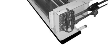
297 289
298 INSTALLATION & OPERATING MANUAL MHCCX Fan Coils 1-3 Tons CAUTION Care must be taken when handling sheet metal. Sheet metal parts have sharp edges and could cause injury. GENERAL Read the entire contents of this manual before beginning installation. Multiaqua assumes no responsibility for equipment installed contradictory to any code requirement or installation instructions. The components of this fan coil have been inspected at the factory and readied for shipment. Upon receiving the shipment a visual inspection of the packaging must be performed. If any damage to the packaging is discovered, an inspection of the components must be performed and noted on the delivery documents. If component damage is found a damage claim must be filed by the receiving party against the delivery party immediately. This product is designed and manufactured to permit installation in accordance with national codes. It is the installer s responsibility to install the product in accordance with national codes and/or prevailing local codes and regulations. Care must be taken to ensure the structural integrity of the supporting members, clearances and provisions for servicing, power supply, coil connections and/or condensate removal. Before the installation ensure the structural strength of the supporting members is sufficient. See figure 1 for hanging weights of the fan coils. This unit is designed to be installed in a horizontal configuration only and into an enclosure assembly. The enclosure assembly can be ordered separately or field fabricated by the installing contractor. See figure 2 for enclosure part numbers, dimensions and weights. See document number for enclosure assembly and installation instructions. See figure 3 for fan coil only dimensions. The coil hand of connection is field reversible. See figures 4-6 for converting the coil hand of connection. FAN COIL APPROXIMATED MODEL NUMBER WEIGHTS (LBS) MHCCX MHCCX MHCCX MHCCX MHCCX Figure 1 ENCLOSURE DIMENSIONS ENCLOSURE FAN COIL (us) PART NUMBER SIZE Depth Length Height Weight MPE MPE MPE MPE MPE Figure 2 290
299 INSTALLATION & OPERATING INSTRUCTIONS MHCCX Fan Coils 1-3 Tons FAN COIL DIMENSIONS Fan Coil Model Number A B C D E F MHCCX04-XX MHCCX06-XX MHCCX08-XX MHCCX10-XX MHCCX12-XX TXV D E.75 (MPT) Condensate Drain Connection (Both Ends) 1 F C B A Mounting Notches Drain Pan Figure 3 291
300 INSTALLATION & OPERATING MANUAL MHCCX Fan Coils 1-3 Tons CAUTION Care must be taken when handling sheet metal. Sheet metal parts have sharp edges and could cause injury. INSTRUCTIONS FOR CONVERTING COIL HAND OF CONNECTION & ELECTRIC HEATER ACCESS. Figure 4 1. Remove the eleven screws that attach the top to the fan coil assembly and remove the top. This will allow you to access the electric heaters. Figure 4 2. Remove the eight screws that hold the coil into the fan coil frame assembly. Four screws per side. Figure 5 3 Slide the coil out of the fan coil frame assembly toward the coil supply and return line connections. Ensure that care is taken when removing and inserting the coil not to damage the coil fins. Insert the coil into the fan coil frame assembly from the other end and reverse procedures 4 & 5 to reassemble the fan coil. Figure 6 Figure 5 Figure 6 292
301 INSTALLATION & OPERATING MANUAL MHCCX Fan Coils 1-3 Tons INSTRUCTIONS FOR INSTALLING FAN COIL UNIT INTO ENCLOSURE ASSEMBLY 1. Remove the ten screws that attach the electrical assembly to the fan coil unit. Do not separate the electrical assembly from the blower assembly. These two assemblies will be removed in the next step. Figure 7 Figure 7 2. Remove the five screws attaching the blower assembly to the coil assembly. Separate the electrical and blower assemblies from the coil assembly. Figure 8 3. Insert the coil assembly into the enclosure assembly starting with the discharge air opening of the coil first. Ensure that the discharge of the coil is inserted into the discharge of the enclosure completely. Failure to completely insert the coil discharge will result in recirculation of the discharge air. Figure 9 Figure 8 Figure 9 293
302 INSTALLATION & OPERATING MANUAL MHCCX Fan Coils 1-3 Tons 4. Align the fan coil mounting bolts up with the four mounting notches provided in the coil assembly top. Secure the coil assembly to the enclosure with two mounting bolts per side. Ensure that the coil assembly is level in both directions to allow proper drainage and operation. Figure Reinstall the blower assembly onto the coil assembly using the five screws previously removed in step 2 figure 8. Figure 11 Figure Reinstall the electrical assembly onto the coil assembly using the ten screws previously removed in step 1 figure 7. Figure 12 ELECTRICAL, COIL, DRAIN AND RETURN / SUPPLY AIR LOCATIONS Figure There are multiple entry points on the factory supplied enclosure assembly for water lines, condensate lines, refrigerant lines and electrical connections. If a non-louvered service access panel is used or if an alternate return air location is required an optional return air cutout is provided. Figure 13 Figure
303 INSTALLATION & OPERATING MANUAL MHCCX Fan Coils 1-3 Tons ELECTRICAL & CONDENSATE DRAIN 8. There are four termination points for the electrical wiring. There are two on each side of the electrical box. See pages for electrical drawings. Wiring must be installed according to prevailing codes and regulations. The fan coil unit has one condensate drain connection on either side of the drain pan for either left or right hand drain connection. The opposite drain connection not being used must be capped off by the installing contractor. The middle drain connection is the safety condensate drain connection. Ensure that all condensate drain lines have at least one quarter of an inch of fall per foot for proper drainage. Figure 14 DIRECT EXPANSION COIL CONNECTIONS 9. The fan coil unit comes with a Thermal Expansion Valve installed on the DX coil. Ensure that the suction line is insulated all the way to the coil header and the liquid line is insulated from the TXV to the distributor. Entry Points Typical Both Ends Figure 13 Electrical Terminations Figure 14 Points Figure 14 Optional Return Air Cutout Left and Right Hand Drain Connections Safety Drain Connection Figure 15 Figure
304 INSTALLATION & OPERATION MANUAL MHCCX Fan Coils 1-3 Tons RETURN AND SUPPLY AIR CONNECTIONS 10. When mounting the service access panel, louvered or non-louvered, the installing contractor must provide a frame in order to connect the enclosure assembly to the service access panel. This is required to obtain an airtight seal for the return air. Ensure that the material used for the frame adheres to national codes and / or local codes and regulations. Care must be taken when installing the service access panel to ensure the opening of the hinged service panel. Figure 16 & Filters are not supplied with the fan coil unit or the service access panel. The filter(s) must be supplied by the installing contractor. If a louvered service access panel is used the filter will mount on the under side of the hinged access panel. If the optional return air cutout is used it is recommended that a return air filter grille be used that has the same surface area as the recommended filter sizes. Figure 18 Fan Coil Mounting Bolts Typical All Four Corners Fan Coil Enclosure Supply Duct Flange Optional Return Air Cutout Frame Enclosure Supplied By Installing Contractor Ceiling Hinged Service Access Panel Louvered Panel Shown. An Optional Non-louvered Service Access Panel Is Available. Return Air Figure 16 Panel Mounting Screw ( TYP) 296
305 INSTALLATION & OPERATION MANUAL MHCCX Fan Coils 1-3 Tons SERVICE ACCESS PANEL DIMENSIONS Panel Model Number Louvered & Non-Louvered Fan Coil Size A (in) B (in) C (in) MAP468L(NL) MAP468L(NL) MAP468L(NL) MAP10L (NL) MAP12L (NL) A B C (typ) Figure 17 FAN COIL MODEL RECOMMENDED FILTER SIZES NUMBER Width (in) Length (in) MHCCX MHCCX MHCCX MHCCX MHCCX12 2 qty Figure
306 INSTALLATION & OPERATION MANUAL MHCCX Fan Coils 1-3 Tons 12. The fan coil enclosure assembly has a supply air duct flange to allow the attachment of ductwork. Ensure when attaching ductwork to the flange that the screws are at least one and half inches away from the front of the enclosure. This is to allow proper insertion of the fan coil assembly into the enclosure assembly when duct work will be installed before the fan coil is installed. Figure 19 SUPPLY AIR DUCT FLANGE Enclosure Model Number Fan Coil Size A (in) B (in) MAP468L(NL) MAP468L(NL) MAP468L(NL) MAP10L (NL) MAP12L (NL) A B Figure
307 INSTALLATION & OPERATION MANUAL MHCCX Fan Coils 1-3 Tons MAITENANCE 1. Air Filter(s): Filters are an essential part of the quality of air that is provided to the occupants. Never operate HVAC equipment without filters. Filters help remove dust and unwanted particles from the air stream, helping to keep the space clean. They also keep this debris from collecting on the heat transfer surfaces of the unit thus maintaining optimum equipment efficiency and performance. These filters will be located either in the unit or upstream from the unit in the return air ductwork. Filters must be inspected, cleaned and/or changed routinely. This routine maintenance procedure will allow the unit to continually operate as designed, reduce service expenses and extend equipment/component life. and/or replacements in the event the unit fails to operate or is being serviced. If fuses are used, ensure that the replacement fuses are of the same size and type as the ones you are replacing. It is a good idea to keep replacement fuses of the appropriate size and type on hand. 3. Routine Check Up and Service: This product is designed to provide many years of dependable, trouble free comfort when properly maintained. Proper maintenance will consist of routine filter cleanings/changes, bi-annual check ups that include but not limited to filter inspections, electric heater inspections /cleaning of the internal electrical and heat transfer components by a qualified service technician. Failure to provide periodic check ups and cleaning can result in excessive operating cost and/or equipment failure. 2. Fuses and/or Circuit Breakers: This unit must be connected to the buildings electric service in accordance with local/national electrical codes and regulations. These electrical connections will include over current protection in the form of fuses or circuit breakers. Have your contractor identify/label the circuits and the location of them so that you may be in a position to make inspections 299
308 MHCCX Without Electric Heat Wiring Diagram 208/ /60 300
309 MHCCX with Electric Heat Wiring Diagram 208/ /60 301
310 MHCCX with 2KW Electric Heat Wiring Diagram /60 302
311 MHCCX without Electric Heat Wiring Diagram /60 303
312 MHCCX CERTIFIED DRAWING 304
313 MCCX Direct Expansion Ceiling Concealed Direct Expansion Fan Coil 48,000-60,000 BTUH 305
314 MCCX NOMENCLATURE BREAKDOWN Direct Expansion Ceiling Concealed Fan Coil MCCX- XX - C -1 Direct Expansion Cooling Voltage 1=208/230/-1-50/60 Nominal Tons 16= 4 ton 20= 5 ton Available Model Numbers MCCX-16-C-1 MCCX-20-C-1 306
315 HVAC Guide Specifications Direct Expansion Fan Coil Nominal Size: 48,000 60,000 BTUH Multiaqua Model Number: MCCX16 MCCX20 Part 1-General 1.01 System Description Multiaqua Direct Expansion Fan Coils are manufactured with heavy gauge galvanized steel to resist corrosion Quality Assurance A. Certified in accordance with U.L. Standard 95, latest version (U.S.A.) B. Manufactured in a facility registered to ISO 9002, Manufacturing Quality Standard. C. Fully load tested at the factory. D. Damage resistant packaging Delivery, Storage and Handling A. Packaged and readied for shipment from the factory. B. Controls shall be capable of withstanding 150 F storage temperatures in the control compartment. C. Stored and handled per manufacturer s recommendations. Part 2-Product 2.01 Equipment A. General: 1. Unit shall be a factory assembled and tested direct expansion fan coil. 2. Shall be assembled with heavy gauge galvanized steel. 3. Contained with the unit shall be all factory wiring, piping, associated controls and special accessories required prior to start up. B. Unit Cabinet: 1. Composed of heavy gauge galvanized steel casing with a baked polyester powder. 2. Shall be internally insulated to insure quiet operation. C. Fan Motors: 1. Shall be available in 208/ /60 vac. 1. Fan motors shall be three speed, direct drive, and PSC type. 2. Totally enclosed. 3. Internal overload protected. D. Blower Wheels: 1. Blower wheels are forward curved and dynamically balanced. E. DX Coil: 1. Manufactured with 3/8 copper rifled tubing mechanically bonded to aluminum fins. 2. Contain a thermal expansion valve. 3. Coils shall be factory tested to 350 psig. 4. Coils shall be capable of being field converted from right to left hand connection. F. Drain Pan: 1. All drain pans shall be coated on both the interior and exterior with baked polyester powder to resist corrosion. 2. The exterior of all drain pans shall be insulated with closed cell to prevent condensation. 3. Pans shall contain a left and right hand primary sloped drain connection as well as a sloped right hand secondary drain connection. 307
316 Part 3-Controls and Safeties 3.01 Controls A. Fan coils shall be completely factory wired and tested. B. All components shall be wired to an internal terminal block to allow for a field installed thermostat and or fan speed control. C. Controls shall include the following components vac transformer. 2. Fan relays. 3. Optional thermostats Safeties: A. Fan coil shall contain a non reusable fuse on the secondary voltage side of the transformer. Part 4-Operating Characteristics: 4.01 Electrical Requirements A. Primary electrical power supply shall enter the unit at a single location. B. Electrical power supply shall be rated to withstand 120 F operating ambient temperatures. D. Control and high voltage points shall be accessed through terminal block. 308
317 MCCX Product Specifications & Capacity Model Number Height (in) Width (in) Depth (in) Weight (lbs) Physical Data Coil Rows FPI Copper Diameter (in) Liquid Line (in) Suction Line (in) MCCX /8 3/8 3/4 1/2 MCCX /8 3/8 3/4 1/2 Drain (in) Electrical Data Model Number Nominal CFM Volts/ Phase/ Hertz Motor HP Full Load Ampacity Fuse or HACR Circuit Breaker Per Circuit Minimum Amps Maximum Amps MCCX-16-C / /60 1/ MCCX-20-C / /60 1/ Performance Data Model Number Nominal CFM Cooling Capacity MCCX-16-C ,000 MCCW-20-C ,000 Nominal CFM vs. External Static Pressure Table Model Hi Speed Number MCCX MCCX These specifications are subject to change without notice. 309
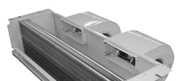

318 310
319 INSTALLATION & OPERATING MANUAL MCCX Fan Coils 4 & 5 Tons CAUTION Care must be taken when handling sheet metal. Sheet metal parts have sharp edges and could cause injury. GENERAL Read the entire contents of this manual before beginning installation. Multiaqua assumes no responsibility for equipment installed contradictory to any code requirement or installation instructions. The components of this fan coil have been inspected at the factory and readied for shipment. Upon receiving the shipment a visual inspection of the packaging must be performed. If any damage to the packaging is discovered, an inspection of the components must be performed and noted on the delivery documents. If component damage is found a damage claim must be filed by the receiving party against the delivery party immediately. This product is designed and manufactured to permit installation in accordance with national codes. It is the installer s responsibility to install the product in accordance with national codes and/or prevailing local codes and regulations. Care must be taken to ensure the structural integrity of the supporting members, clearances and provisions for servicing, power supply, coil connections and/or condensate removal. Before the installation ensure the structural strength of the supporting members is sufficient. See figure 1 for hanging weights of the fan coils. This unit is designed to be installed in a horizontal configuration only. See figure 2 for fan coil dimensions. The coil hand of connection is field reversible. See figures 4-6 for converting the coil hand of connection. FAN COIL APPROXIMATED MODEL NUMBER WEIGHTS (LBS) MCCX MCCX Figure 1 311

320 INSTALLATION & OPERATING INSTRUCTIONS MCCX Fan Coils 4 & 5 Tons FAN COIL DIMENSIONS (in) Fan Coil Model Number A B C D E F MCCX MCCX TXV D E.75 (MPT) Condensate Drain Connection (Both Ends) 1 F C B A Mounting Notches Drain Pan Figure 2 312


321 INSTALLATION & OPERATING MANUAL MCCX Fan Coils 4 & 5 Tons CAUTION Care must be taken when handling sheet metal. Sheet metal parts have sharp edges and could cause injury. INSTRUCTIONS FOR CONVERTING COIL HAND OF CONNECTION Figure 3 1. Remove the eleven screws that attach the top to the fan coil assembly and remove the top. This will allow you to access the electric heaters. Figure 3 2. Remove the eight screws that hold the coil into the fan coil frame assembly. Four screws per side. Figure 4 3 Slide the coil out of the fan coil frame assembly toward the coil supply and return line connections. Ensure that care is taken when removing and inserting the coil not to damage the coil fins. Insert the coil into the fan coil frame assembly from the other end and reverse procedures 3 & 4 to reassemble the fan coil. Figure 5 Figure 4 Figure 5 313

322 INSTALLATION & OPERATING MANUAL MCCX Fan Coils 4 & 5 Tons ELECTRICAL & CONDENSATE DRAIN 4. There are four termination points for the electrical wiring. There are two on each side of the electrical box. See page 316 for electrical drawing. Wiring must be installed according to prevailing codes and regulations. The fan coil unit has one condensate drain connection on either side of the drain pan for either left or right hand drain connection. The opposite drain connection not being used must be capped off by the installing contractor. The middle drain connection is the safety condensate drain connection. Ensure that all condensate drain lines have at least one quarter of an inch of fall per foot for proper drainage. Figure 6 DIRECT EXPANSION COIL CONNECTIONS 5. The fan coil unit comes with a Thermal Expansion Valve installed on the DX coil. Ensure that the suction line is insulated all the way to the coil header and the liquid line is insulated from the TXV to the distributor. Left and Right Hand Drain Connections Electrical Terminations Figure 14 Points Safety Drain Connection Figure 6 Figure 7 Figure 7 314
323 INSTALLATION & OPERATION MANUAL MCCX Fan Coils 4 & 5 Tons MAITENANCE 1. Air Filter(s): Filters are an essential part of the quality of air that is provided to the occupants. Never operate HVAC equipment without filters. Filters help remove dust and unwanted particles from the air stream, helping to keep the space clean. They also keep this debris from collecting on the heat transfer surfaces of the unit thus maintaining optimum equipment efficiency and performance. These filters will be located either in the unit or upstream from the unit in the return air ductwork. Filters must be inspected, cleaned and/or changed routinely. This routine maintenance procedure will allow the unit to continually operate as designed, reduce service expenses and extend equipment/component life. and/or replacements in the event the unit fails to operate or is being serviced. If fuses are used, ensure that the replacement fuses are of the same size and type as the ones you are replacing. It is a good idea to keep replacement fuses of the appropriate size and type on hand. 3. Routine Check Up and Service: This product is designed to provide many years of dependable, trouble free comfort when properly maintained. Proper maintenance will consist of routine filter cleanings/changes, bi-annual check ups that include but not limited to filter inspections, electric heater inspections /cleaning of the internal electrical and heat transfer components by a qualified service technician. Failure to provide periodic check ups and cleaning can result in excessive operating cost and/or equipment failure. 2. Fuses and/or Circuit Breakers: This unit must be connected to the buildings electric service in accordance with local/national electrical codes and regulations. These electrical connections will include over current protection in the form of fuses or circuit breakers. Have your contractor identify/label the circuits and the location of them so that you may be in a position to make inspections 315
324 MHCCX Without Electric Heat Wiring Diagram 208/ /60 316

325 MCCX CERTIFIED DRAWING 317
326 MHNCCX DX with Hot Water Heat Ceiling Concealed 4-Pipe Heat / Cool Fan Coil 12,000-36,000 BTUH 318
327 MHNCCX NOMENCLATURE BREAKDOWN 4-Pipe Heat/Cool Ceiling Concealed Fan Coil MHNCCW- XX - XX Ceiling Concealed 4-Pipe DX Cool/HW Heat Voltage 01= 208/ /60 03= /60 Nominal Tons 04 = 1 Ton 06 = 1.5 Ton 08 = 2 Ton 10 = 2.5 Ton 12 = 3 Ton Available Model Numbers MHNCCX MHNCCX MHNCCX MHNCCX MHNCCX MHNCCX MHNCCX MHNCCX MHNCCX MHNCCX
328 HVAC Guide Specifications Direct Expansion and Hot Water Fan Coil 4-Pipe Nominal Size: 12,000 36,000 BTUH Multiaqua Model Number: MHNCCX04 MHNCCX06 MHNCCX08 MHNCCX10 MHNCCX12 Part 1-General 1.01 System Description Multiaqua DX and Chilled Water Fan Coils are manufactured with heavy gauge galvanized steel to resist corrosion Quality Assurance A. Certified in accordance with U.L. Standard 95, latest version (U.S.A.) B. Manufactured in a facility registered to ISO 9002, Manufacturing Quality Standard. C. Fully load tested at the factory. D. Damage resistant packaging Delivery, Storage and Handling A. Packaged and readied for shipment from the factory. B. Controls shall be capable of withstanding 150 F storage temperatures in the control compartment. C. Stored and handled per manufacturer s recommendations. Part 2-Product 2.01 Equipment A. General: 1. Unit shall be a factory assembled and tested DX and hot water fan coil. 2. Shall be assembled with heavy gauge galvanized steel. 3. Contained with the unit shall be all factory wiring, piping, associated controls and special accessories required prior to start up. B. Unit Cabinet: 1. Composed of heavy gauge galvanized steel casing with a baked polyester powder. 2. Shall be internally insulated to insure quiet operation. C. Fan Motors: 1. Shall be available in /60 and 208/ /60 vac. 1. Fan motors shall be three speed, direct drive, and PSC type. 2. Totally enclosed. 3. Internal overload protected. D. Blower Wheels: 1. Blower wheels are forward curved and dynamically balanced. E. Water Coil: 1. Manufactured with water coils containing 3/8 copper tubing mechanically bonded to aluminum fins. 2. Contain both a manual water drain and manual air bleed port per coil. 3. Coils shall be factory tested to 350 psig. 4. Coils shall be capable of being field converted from right to left hand connection. F. Direct Expansion Coil: 1. Manufactured with water coils containing 3/8 copper tubing mechanically bonded to aluminum fins. 2. Will contain a thermal expansion valve. 3. Coils shall be tested to 350 psig. 4. Coils shall be capable of being field converted from right to left hand connection. 320
329 G. Drain Pan: a. All drain pans shall be coated on both the interior and exterior with baked polyester powder to resist corrosion. b. The exterior of all drain pans shall be insulated with closed cell to prevent condensation. c. Pans shall contain a left and right hand primary sloped drain connection as well as a sloped right hand secondary drain connection. Part 3-Controls and Safeties 3.01 Controls A. Fan coils shall be completely factory wired and tested. B. All components shall be wired to an internal terminal block to allow for a field installed thermostat and or fan speed control. C. Controls shall include the following components vac transformer. 2. Fan relays. 3. Optional thermostats Safeties: A. Fan coil shall contain a non reusable fuse on the secondary voltage side of the transformer. Part 4-Operating Characteristics: 4.01 Electrical Requirements A. Primary electrical power supply shall enter the unit at a single location. B. Electrical power supply shall be rated to withstand 120 F operating ambient temperatures. D. Control and high voltage points shall be accessed through terminal block. Part 5- Accessories: 5.01 Enclosures A. Fan coils shall be capable of incorporating enclosures. 1. Enclosures shall be internally insulated to insure quite operation and increase efficiency. 2. Shall include knockouts for ease of piping/ electrical in and out of the enclosures. 3. Shall include an optional return air cutout in the enclosure. 4. Shall include a supply air duct flange. 5. Shall incorporate baked polyester powder service access panels with and without a filter louver. 321
330 MHNCCX Product Specifications Physical Data Model Number Height (in) Length (in) Depth (in) Weight (lbs) DX Rows FPI H/W Rows FPI Copper Diameter (in) Liquid Line (in) Suction Line (in) Water Inlet (in) Water Outlet (in) Drain (in) MHNCCX04-01(03) /8 3/8 1/2 5/8 5/8 3/4 MHNCCX06-01(03) /8 3/8 5/8 5/8 5/8 3/4 MHNCCX08-01(03) /8 3/8 5/8 5/8 5/8 3/4 MHNCCX10-01(03) /8 3/8 5/8 7/8 7/8 3/4 MHNCCX12-01(03) /8 3/8 5/8 7/8 7/8 3/4 Model Number Nominal CFM Electrical Data Volts/ Phase/ Hertz Motor HP Full Load Ampacity Fuse or HACR Circuit Breaker Per Circuit Minimum Amps Maximum Amps MHNCCX / /60 1/ MHNCCX / MHNCCX / /60 1/ MHNCCX / MHNCCX / /60 1/ MHNCCX / MHNCCX / /60 1/ MHNCCX / MHNCCX / /60 1/ MHNCCX / These specifications are subject to change without notice. 322
331 MHCCX DX Cooling Performance Data, CFM vs. ESP and Glycol Adjustment Model Number Nominal CFM Nominal Cooling BTUH MHNCCX ,000 MHNCCX ,000 MHNCCX ,000 MHNCCX ,000 MHNCCX ,000 MHNCCX ,000 MHNCCX ,000 30,000 MHNCCX ,000 30,000 MHNCCX ,200 36,000 MHNCCX ,200 36,000 * Cooling based on 75 % Sensible and 25% Latent: * Fan coils are 13 SEER CFM vs. External Static Pressure Table Model Number External Static Pressure MHNCCX MHNCCX MHNCCX MHNCCX MHNCCX Propylene Glycol/GPM Adjustment Factors Capacity Ambient Propylene GPM Adjustment Reduction Temp Glycol % = 100% Capacity 26 F 10% x 0.99 x F 20% x 0.98 x F 30% x 0.98 x F 40% x 0.97 x F 50% x 0.96 x 1.16 These specifications are subject to change without notice. 323
332 MHNCCX Heating Capacity Adjustment Factors HOT WATER CAPACITY CORRECTION FACTORS MODEL # MHNCCX04 MHNCCX06 MHNCCX08 MHNCCX10 MHNCCX12 CFM TC SC TC SC TC SC TC SC TC SC These specifications are subject to change without notice. 324
333 MHNCCX Hot Water Performance Data ENTERING AIR ( F) NOMINAL CFM MHNCCX-04 HEATING CAPACITIES ENTERING WATER TEMPERATURE ( F) GPM WPD ENTERING AIR ( F) NOMINAL CFM MHNCCX-04 HEATING CAPACITIES ENTERING WATER TEMPERATURE ( F) GPM WPD ENTERING AIR ( F) NOMINAL CFM MHNCCX-04 HEATING CAPACITIES ENTERING WATER TEMPERATURE ( F) GPM WPD ENTERING AIR ( F) NOMINAL CFM MHNCCX-04 HEATING CAPACITIES ENTERING WATER TEMPERATURE ( F) GPM WPD These specifications are subject to change without notice. 325
334 MHNCCX Hot Water Performance Data ENTERING AIR ( F) NOMINAL CFM MHNCCX-06 HEATING CAPACITIES ENTERING WATER TEMPERATURE ( F) GPM WPD ENTERING AIR ( F) NOMINAL CFM MHNCCX-06 HEATING CAPACITIES ENTERING WATER TEMPERATURE ( F) GPM WPD ENTERING AIR ( F) NOMINAL CFM MHNCCX-06 HEATING CAPACITIES ENTERING WATER TEMPERATURE ( F) GPM WPD ENTERING AIR ( F) NOMINAL CFM MHNCCX-06 HEATING CAPACITIES ENTERING WATER TEMPERATURE ( F) GPM WPD These specifications are subject to change without notice. 326
335 MHNCCX Hot Water Performance Data ENTERING AIR ( F) NOMINAL CFM MHNCCX-08 HEATING CAPACITIES ENTERING WATER TEMPERATURE ( F) GPM WPD ENTERING AIR ( F) NOMINAL CFM MHNCCX-08 HEATING CAPACITIES ENTERING WATER TEMPERATURE ( F) GPM WPD ENTERING AIR ( F) NOMINAL CFM MHNCCX-08 HEATING CAPACITIES ENTERING WATER TEMPERATURE ( F) GPM WPD ENTERING AIR ( F) NOMINAL CFM MHNCCX-08 HEATING CAPACITIES ENTERING WATER TEMPERATURE ( F) GPM WPD These specifications are subject to change without notice. 327
336 MHNCCX Hot Water Performance Data ENTERING AIR ( F) NOMINAL CFM MHNCCX-10 HEATING CAPACITIES ENTERING WATER TEMPERATURE ( F) GPM WPD ENTERING AIR ( F) NOMINAL CFM MHNCCX-10 HEATING CAPACITIES ENTERING WATER TEMPERATURE ( F) GPM WPD ENTERING AIR ( F) NOMINAL CFM MHNCCX-10 HEATING CAPACITIES ENTERING WATER TEMPERATURE ( F) GPM WPD ENTERING AIR ( F) NOMINAL CFM MHNCCX-10 HEATING CAPACITIES ENTERING WATER TEMPERATURE ( F) GPM WPD These specifications are subject to change without notice. 328
337 MHNCCX Hot Water Performance Data ENTERING AIR ( F) NOMINAL CFM MHNCCX-12 HEATING CAPACITIES ENTERING WATER TEMPERATURE ( F) GPM WPD ENTERING AIR ( F) NOMINAL CFM MHNCCX-12 HEATING CAPACITIES ENTERING WATER TEMPERATURE ( F) GPM WPD ENTERING AIR ( F) NOMINAL CFM MHNCCX-12 HEATING CAPACITIES ENTERING WATER TEMPERATURE ( F) GPM WPD ENTERING AIR ( F) NOMINAL CFM MHNCCX-12 HEATING CAPACITIES ENTERING WATER TEMPERATURE ( F) GPM WPD These specifications are subject to change without notice. 329
338 330
339 INSTALLATION & OPERATING MANUAL MHNCCX Fan Coils 1-3 Tons CAUTION Care must be taken when handling sheet metal. Sheet metal parts have sharp edges and could cause injury. GENERAL Read the entire contents of this manual before beginning installation. Multiaqua assumes no responsibility for equipment installed contradictory to any code requirement or installation instructions. The components of this fan coil have been inspected at the factory and readied for shipment. Upon receiving the shipment a visual inspection of the packaging must be performed. If any damage to the packaging is discovered, an inspection of the components must be performed and noted on the delivery documents. If component damage is found a damage claim must be filed by the receiving party against the delivery party immediately. This product is designed and manufactured to permit installation in accordance with national codes. It is the installer s responsibility to install the product in accordance with national codes and / or prevailing local codes and regulations. Care must be taken to ensure the structural integrity of the supporting members, clearances and provisions for servicing, power supply, coil connections and/or condensate removal. Before the installation ensure the structural strength of the supporting members is sufficient. See figure 1 for hanging weights of the fan coils. This unit is designed to be installed in a horizontal configuration only and into an enclosure assembly. The enclosure assembly can be ordered separately or field fabricated by the installing contractor. See figure 2 for enclosure part numbers, dimensions and weights. See document number for enclosure assembly and installation instructions. See figure 3 for fan coil only dimensions. The coil hand of connection is field reversible. See figures 4-6 for converting the coil hand of connection. FAN COIL APPROXIMATED MODEL NUMBER WEIGHTS (LBS) MHNCCX MHNCCX MHNCCX MHNCCX MHNCCX ENCLOSURE FAN COIL PART NUMBER SIZE Figure 1 ENCLOSURE DIMENSIONS (us) Depth Length Height Weight MPE MPE MPE MPE MPE Figure 2 331

340 INSTALLATION & OPERATING INSTRUCTIONS MHNCCX Fan Coils 1-3 Tons FAN COIL DIMENSIONS Fan Coil Model Number A B C D E F MHNCCX MHNCCX MHNCCX MHNCCX MHNCCX Air Vent Hot Water Supply Hot Water Return D E TXV & Liquid Line Coil Drain Suction Line B 1 F.75 (MPT) Condensate Drain Connection (Both Ends) C Mounting Notches A Drain Pan Figure 3 332

341 INSTALLATION & OPERATING MANUAL MHNCCX Fan Coils 1-3 Tons CAUTION Care must be taken when handling sheet metal. Sheet metal parts have sharp edges and could cause injury. INSTRUCTIONS FOR CONVERTING COIL HAND OF CONNECTION Figure 4 1. Remove the eleven screws that attach the top to the fan coil assembly and remove the top. Figure 4 2. Remove the sixteen screws that hold the coils into the fan coil frame assembly. Four screws per each side of the coils. Figure 5 3 Slide the coils out of the fan coil frame assembly toward the coil headers. Ensure that care is taken when removing and inserting the coils not to damage the coil fins. Insert the coils into the fan coil frame assembly from the other end and reverse procedures 4 & 5 to reassemble the fan coil. Figure 6 Figure 5 Figure 6 333
342 INSTALLATION & OPERATING MANUAL MHNCCX Fan Coils 1-3 Tons INSTRUCTIONS FOR INSTALLING FAN COIL UNIT INTO ENCLOSURE ASSEMBLY 1. Remove the ten screws that attach the electrical assembly to the fan coil unit. Do not separate the electrical assembly from the blower assembly. These two assemblies will be removed in the next step. Figure 7 Figure 7 2. Remove the five screws attaching the blower assembly to the coil assembly. Separate the electrical and blower assemblies from the coil assembly. Figure 8 3. Insert the coil assembly into the enclosure assembly starting with the discharge air opening of the coil first. Ensure that the discharge of the coil is inserted into the discharge of the enclosure completely. Failure to completely insert the coil discharge will result in recirculation of the discharge air. Figure 9 Figure 8 Figure 9 334
343 INSTALLATION & OPERATING MANUAL MHNCCX Fan Coils 1-3 Tons 4. Align the fan coil mounting bolts up with the four mounting notches provided in the coil assembly top. Secure the coil assembly to the enclosure with two mounting bolts per side. Ensure that the coil assembly is level in both directions to allow proper drainage and operation. Figure Reinstall the blower assembly onto the coil assembly using the five screws previously removed in step 2 figure 8. Figure 11 Figure Reinstall the electrical assembly onto the coil assembly using the ten screws previously removed in step 1 figure 7. Figure 12 ELECTRICAL, COIL, DRAIN AND RETURN / SUPPLY AIR LOCATIONS Figure There are multiple entry points on the factory supplied enclosure assembly for water lines, condensate lines, refrigerant lines and electrical connections. If a non-louvered service access panel is used or if an alternate return air location is required an optional return air cutout is provided. Figure 13 Figure


344 INSTALLATION & OPERATING MANUAL MHNCCX Fan Coils 1-3 Tons ELECTRICAL & CONDENSATE DRAIN 8. There are four termination points for the electrical wiring. There are two on each side of the electrical box. See pages 341 & 342 for electrical drawings. Wiring must be installed according to prevailing codes and regulations. The fan coil unit has one condensate drain connection on either side of the drain pan for either left or right hand drain connection. The opposite drain connection not being used must be capped off by the installing contractor. The middle drain connection is the safety condensate drain connection. Ensure that all condensate drain lines have at least one quarter of an inch of fall per foot for proper drainage. Figure 14 COIL CONNECTIONS 9. The fan coil unit comes with a manual air bleed and a manual coil drain fitting on the hot water coil. The water supply line is to be connected to the coil connection furthest away from the fans. The water return line is connected to the coil connection closest to the fans. The DX coil comes with a factory installed TXV. Ensure that the supply / return lines on the water coil, the DX suction line and the DX liquid line after the TXV are insulated per code. Figure 15 Entry Points Typical Both Ends Manual Coil Drain Suction Line Figure 13 Electrical Terminations Figure 14 Points Figure 14 Optional Return Air Cutout Left and Right Hand Drain Connections Manual Coil Air Bleed Figure 15 Figure 15 Safety Drain Connection Water Supply Water Return Liquid Line & TXV 336
345 INSTALLATION & OPERATION MANUAL MHNCCX Fan Coils 1-3 Tons RETURN AND SUPPLY AIR CONNECTIONS 10. When mounting the service access panel, louvered or non-louvered, the installing contractor must provide a frame in order to connect the enclosure assembly to the service access panel. This is required to obtain an airtight seal for the return air. Ensure that the material used for the frame adheres to national codes and / or local codes and regulations. Care must be taken when installing the service access panel to ensure the opening of the hinged service panel. Figure 16 & Filters are not supplied with the fan coil unit or the service access panel. The filter(s) must be supplied by the installing contractor. If a louvered service access panel is used the filter will mount on the under side of the hinged access panel. If the optional return air cutout is used it is recommended that a return air filter grille be used that has the same surface area as the recommended filter sizes. Figure 18 Fan Coil Mounting Bolts Typical All Four Corners Fan Coil Enclosure Supply Duct Flange Optional Return Air Cutout Frame Enclosure Supplied By Installing Contractor Ceiling Hinged Service Access Panel Louvered Panel Shown Return Air Figure 16 Panel Mounting Screw ( TYP) 337
346 INSTALLATION & OPERATION MANUAL MHNCCX Fan Coils 1-3 Tons SERVICE ACCESS PANEL DIMENSIONS Louvered & Non-Louvered Fan A B C Coil (in) (in) (in) Panel Model Number Size MAP468L (NL) MAP468L (NL) MAP468L (NL) MAP10L (NL) MAP12L (NL) A B C (typ) Figure 17 FAN COIL MODEL RECOMMENDED FILTER SIZES NUMBER Width (in) Length (in) MHNCCX MHNCCX MHNCCX MHNCCX MHNCCX12 2 qty Figure
347 INSTALLATION & OPERATION MANUAL MHNCCX Fan Coils 1-3 Tons 12. The fan coil enclosure assembly has a supply air duct flange to allow the attachment of ductwork. Ensure when attaching ductwork to the flange that the screws are at least one and half inches away from the front of the enclosure. This is to allow proper insertion of the fan coil assembly into the enclosure assembly when duct work will be installed before the fan coil is installed. Figure 19 SUPPLY AIR DUCT FLANGE Fan A Enclosure Model Number Coil (in) Size B (in) MAP468L(NL) MAP468L(NL) MAP468L(NL) MAP10L (NL) MAP12L (NL) A B Figure
348 INSTALLATION & OPERATION MANUAL MHNCCX Fan Coils 1-3 Tons MAITENANCE 1. Air Filter(s): Filters are an essential part of the quality of air that is provided to the occupants. Never operate HVAC equipment without filters. Filters help remove dust and unwanted particles from the air stream, helping to keep the space clean. They also keep this debris from collecting on the heat transfer surfaces of the unit thus maintaining optimum equipment efficiency and performance. These filters will be located either in the unit or upstream from the unit in the return air ductwork. Filters must be inspected, cleaned and/or changed routinely. This routine maintenance procedure will allow the unit to continually operate as designed, reduce service expenses and extend equipment/component life. and/or replacements in the event the unit fails to operate or is being serviced. If fuses are used, ensure that the replacement fuses are of the same size and type as the ones you are replacing. It is a good idea to keep replacement fuses of the appropriate size and type on hand. 3. Routine Check Up and Service: This product is designed to provide many years of dependable, trouble free comfort when properly maintained. Proper maintenance will consist of routine filter cleanings/changes, bi-annual check ups that include but not limited to filter inspections, inspections /cleaning of the internal electrical and heat transfer components by a qualified service technician. Failure to provide periodic check ups and cleaning can result in excessive operating cost and/or equipment failure. 2. Fuses and/or Circuit Breakers: This unit must be connected to the buildings electric service in accordance with local/national electrical codes and regulations. These electrical connections will include over current protection in the form of fuses or circuit breakers. Have your contractor identify/label the circuits and the location of them so that you may be in a position to make inspections 340
349 MHNCCX-xx-01 Wiring Diagram 208/230/-1-50/60 341
350 MHNCCX-xx-03 Wiring Diagram /60 342
351 MHNCCX CERTIFIED DRAWING 343

352 MHWX Direct Expansion Hi-Wall Fan Coil Direct Expansion Fan Coil 9,000-36,000 BTUH 344
353 MHWX NOMENCLATURE BREAKDOWN Direct Expansion Hi-Wall Fan Coil MHWX- XX - X -1 Hi-Wall Direct Expansion Voltage 1=208/230/-1-50/60 Modes C = DX Cooling Only H = DX Heat Pump Nominal BTUH 09=9,000 12=12,000 18=18,000 24=24,000 36=36,000 Available Model Numbers MHWX-09-C-1 MHWX-12-C-1 MHWX-18-C-1 MHWX-24-C-1 MHWX-36-C-1 MHWX-09-H-1 MHWX-12-H-1 MHWX-18-H-1 MHWX-24-H-1 MHWX-36-H-1 345
354 HVAC Guide Specifications Direct Expansion Hi-Wall Fan Coil Nominal Size: 9,000 36,000 BTUH Multiaqua Model Number: MHWX-09 MHWX-12 MHWX-18 MHWX-24 MHWX-36 Part 1-General 1.01 System Description Multiaqua Direct Expansion Fan Coils are manufactured with high impact molded polymers Quality Assurance A. Certified in accordance with U.L. Standard 95, latest version (U.S.A.) B. Manufactured in a facility registered to ISO 9002, Manufacturing Quality Standard. C. Fully load tested at the factory. D. Damage resistant packaging Delivery, Storage and Handling A. Packaged and readied for shipment from the factory. B. Controls shall be capable of withstanding 150 F storage temperatures in the control compartment. C. Stored and handled per manufacturer s recommendations. Part 2-Product 2.01 Equipment A. General: 1. Unit shall be a factory assembled direct expansion fan coil. 2. Shall be assembled with high quality. 3. Contained with the unit shall be all factory wiring, piping, associated controls and special accessories required prior to start up. B. Unit Cabinet: 1. Composed of high impact polymers. 2. Shall be internally insulated to insure quiet operation. C. Fan Motors: 1. Shall be available in 208/ /60 vac. 1. Fan motors shall be three speed, direct drive, and PSC type. 2. Totally enclosed. 3. Internal overload protected. 4. Unit shall contain a swing motor to modulate the discharge air. D. Blower Wheels: 1. Blower wheels are tangential and dynamically balanced. E. DX Coil: 1. Coils manufactured with 3/8 rifled copper tubing mechanically bonded to aluminum fins. 2. Coils shall be factory tested to 350 psig. F. Drain Pan: 1. All drain pans shall be molded with high impact polymers. 2. The exterior of all drain pans shall be insulated with closed cell to prevent condensation. 3. Pans shall contain a flexible drain tubing that is accessible from the back of the unit. 346
355 G. Filters: 1. Unit shall contain 65% washable filters. Part 3-Controls and Safeties 3.01 Controls A. Fan coils shall be completely factory wired and tested. B. Shall be capable of heat pump operation. C. Controls shall include a circuit board, room sensor, indoor coil thermistor, transformer and wireless remote. D. Controls shall be capable of incorporating an optional hard-wired thermostat Safeties: A. Fan coil shall contain a non reusable fuse on the secondary voltage side of the transformer. B. Discharge air sensor. Part 4-Operating Characteristics: 4.01 Electrical Requirements A. Unit shall incorporate a three prong male primary electrical power cord. B. Electrical power supply shall be rated to withstand 120 F operating ambient temperatures. 347
356 MHWX Product Specifications & Capacity Model Number Height (in) Width (in) Depth (in) Physical Data Coil Weight Rows (lbs) FPI Copper Diameter (in) Liquid Line (in) Suction Line (in) MHWX /8 1/4 3/8 1/2 MHWX /8 1/4 3/8 1/2 MHWX /8 5/16 1/2 3/4 MHWX /8 3/8 5/8 3/4 MHWX /8 3/8 5/8 3/4 Drain (in) Electrical Data Model Number Hi Speed CFM Volts/ Phase/ Hertz Motor HP Full Load Ampacity Fuse or HACR Circuit Breaker Per Circuit Minimum Amps Maximum Amps MHWX-09-C / MHWX-12-C / / /60 MHWX-18-C / MHWX-24-C / MHWX-36-C / Performance Data Model Number CFM Nominal Cooling Capacity MHWX-09-C ,000 MHWX-12-C ,000 MHWX-18-C ,000 MHWX-24-C ,000 MHWX-36-C ,000 These specifications are subject to change without notice. 348
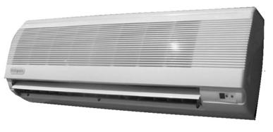
357 \ 349
358 INSTALLATION & OPERATING MANUAL MHWX Hi-Wall Fan Coils 9,000-36,000 BTUH CAUTION Care must be taken when handling sheet metal. Sheet metal parts have sharp edges and could cause injury. GENERAL Read the entire contents of this manual before beginning installation. Multiaqua assumes no responsibility for equipment installed contradictory to any code requirement or installation instructions. The components of this fan coil have been inspected at the factory and readied for shipment. Upon receiving the shipment a visual inspection of the packaging must be performed. If any damage to the packaging is discovered, an inspection of the components must be performed and noted on the delivery documents. If component damage is found a damage claim must be filed by the receiving party against the delivery party immediately. This product is designed and manufactured to permit installation in accordance with national codes. It is the installer s responsibility to install the product in accordance with national codes and/or prevailing local codes and regulations. Care must be taken to ensure the structural integrity of the supporting members, clearances and provisions for servicing, power supply, coil connections and/or condensate removal. Before the installation ensure the structural strength of the supporting members is sufficient. See figure 1 for hanging weights of the fan coils. This unit is designed to be installed in a horizontal configuration only. See figure 2 for fan coil and mounting plate dimensions. FAN COIL APPROXIMATED MODEL NUMBER WEIGHTS (lbs) MHWX-09-C MHWX-12-C MHWX-18-C MHWX-24-C MHWX-36-C Figure 1 350

359 INSTALLATION & OPERATING MANUAL MHWX Hi-Wall Fan Coils 9,000-36,000 BTUH Fan Coil Model Number FAN COIL AND MOUNTING PLATE DIMENSIONS (in) A B C D E F G H I J K Field Supplied Hole L Field Supplied Hole MHWX MHWX MHWX MHWX MHWX A C D B Mounting Plate H G K E F L I J Figure 2 351
360 INSTALLATION & OPERATING MANUAL MHWX Hi-Wall Fan Coils 9,000 36,000 BTUH CAUTION Care must be taken when handling sheet metal. Sheet metal parts have sharp edges and could cause injury. INSTRUCTIONS FOR INSTALLING THE MOUNTING PLATE Figure 3 1. After a suitable place for installation has been selected, place the mounting plate horizontally on the wall. Make sure the alignment is horizontal. Use a plumb line if available. Mark on the wall where the mounting holes will be drilled. Figure 3 2. Drill the holes for the type of mounting hardware to be used. Check local building codes for correct mounting hardware. Secure the mounting plate and check for stiffness. Figure 4 3 Drill a diagonal piping access hole (2.75 ) in diameter on both sides of the mounting bracket. Refer to figure 2 for field supplied hole locations Figure 4 4. Check local and national codes for piping access wall penetrations. See figure 5 if wall sleeves are required. Figure 5 Figure 5 352

361 INSTALLATION & OPERATING MANUAL MHWX Hi-Wall Fan Coils 9,000 36,000 BTUH INSTRUCTIONS FOR INSTALLING FAN COIL UNIT ONTO MOUNTING PLATE 1. Route the fan coil piping, electrical, condenser control wires and/or flexible drain hose through either of the 2.75 previously drilled holes in step 3 figure 4. Ensure that the piping is insulated per local and national codes. Improper insulation could result in voided warranty and/or building damage. Figure 6 Figure 6 2. There is a piping channel in the bottom portion of the back of the units for crossover piping, drain, condenser control wires and/or electrical. Figure 7 Figure 7 3. The TXV can be installed at the unit or condenser. Ensure that the liquid is insulated completely if the TXV is installed at the condenser. 4. Figure 8 depicts (from the back of the unit) the 24 vac condenser control wires on the left and the 220 vac power cord on the right. These can be routed to either the right or left hand side of the fan coil. Figure 8 Figure 8 353

362 INSTALLATION & OPERATING MANUAL MHWX Hi-Wall Fan Coils 9,000 36,000 BTUH INSTRUCTIONS FOR INSTALLING FAN COIL UNIT ONTO MOUNTING PLATE 4. Ensure that the drain tubing is installed with at least 1/4 per foot of downward slope. 5. Secure the fan coil to the mounting plate by first sliding the fan coil onto the two notches provided on the mounting plate. Figure 9 & 10 Figure 9 6. Push the bottom of the fan coil towards the wall in order to engage the locking clips. Figure Connect the refrigerant lines and pressure test lines to make sure there are no leaks. 8. Connect the condensate drain hose. Make certain that the drain has no traps or dips in the line that would impede drainage. Figure Carefully seal any wall penetrations per local and national codes. Figure

 Optional Wired Control: EG-003 (Page")
363 INSTALLATION & OPERATING MANUAL MHWW Hi-Wall Fan Coils 9,000 36,000 BTUH MHWX CONTROLS OPERATION GUIDE Wireless Control: Standard Control Package (Page 355) Optional Wired Control: EG-003 (Page 361) 355
364 INSTALLATION & OPERATING MANUAL MHWX Hi-Wall Fan Coils 9,000 36,000 BTUH MHWX CONTROLS OPERATION GUIDE Wireless Control: Name and function of remote controller Note: Be sure there are no obstructions between receiver and remote controller. The remote control signal can be received at the distance of up to about 21 feet. Do not throw or drop the remote controller. Do not put any liquid in the remote controller and do not put it in direct sunlight or any place where it is very hot. Remove batteries when the remote controller is not in use for extended periods of time. The remote controller should be placed 3 or more feet away from any electric appliance. LED MODE INDICATOR FOR REMOTE CONTROLLER: INDICATOR LIGHTS REMOTE SETTING FUNCTION RED-GREEN COOL COOLING OPERATION ONLY RED-OFF DRY HUMIDITY CONTROL,NO FAN RED-RED HEAT HEATING OPERATION ONLY RED-OFF FAN FAN OPERATION ONLY RED-BLINKING AUTO AUTO SELECTION BETWEEN HEAT & COOL DEPENDENT ON ROOM TEMP & SET TEMP RED-ORANGE ALERT FAN COIL WAITING FOR LAT TO REACH PROPER TEMPERATURE NECESSARY TO SATISFY SET POINT 356
365 INSTALLATION & OPERATING MANUAL MHWX Hi-Wall Fan Coils 9,000 36,000 BTUH MHWX CONTROLS OPERATION GUIDE FUNCTION 1. TRANSMISSION SOURCE - Infra red transmission source 2. POWER - Press to turn the fan coil on and off or vice versa. (Red LED left will light to indicate the control is on) 3. MODE - To select desired operation mode. It will switch from one to another as shown. COOL - Cooling operation. DRY - Humidity control. HEAT - Heating operation. FAN - Fan only. No cooling or heating capability. AUTO - Operation mode will be selected automatically between HEAT and COOL mode, depending upon the room temperature and SET temperature. 4. FAN - To select fan speed. It will switch from one to another as shown below. - When the system temperature sensor is not calling for cool or heat the fan will run at the speed previously entered in fan mode selection (high, medium or low). - If auto was the previously entered fan speed in cooling: The fan will run at low speed until the temperature sensor calls for either heating or cooling at which point the fan will return to auto speed control Fan Speed Sequence 357
366 INSTALLATION & OPERATING MANUAL MHWX Hi-Wall Fan Coils 9,000 36,000 BTUH MHWX CONTROLS OPERATION GUIDE FUNCTION 5. TEMPERATURE SETTING - Press to increase set temperature. - Press to decrease set temperature. - Press and Simultaneously to toggle between C and F display mode. - Temperature range: 16 C to 30 C in C display mode and 60 F to 86 F in F display mode. 6. DELAY TIMER SETTING - The delay timer is capable of delaying both on and off functions. The delay feature will take affect in all modes with the exception of the sleep mode. Each time the and is pressed it increases or decreases the On or OFF set point by 1 hour; up to a maximum of 18 hours. To set the OFF DELAY: With the system in operation, enter the system OFF time by pressing the button to the desired number of hours ahead that the system will be allowed to run. When the number of hours entered has elapsed the system will turn off. To set the ON DELAY: - Set the on delay by entering the desired mode of operation (fan, heat, cool and the appropriate temperature. This will be the settings the system will follow when operation resumes. After setting the mode and any applicable temperature with the control, turn the remote off. Now enter the number of hours to elapse before operation resumes by pressing the button on the remote to the desired number. When the time (in hours) entered has elapsed the system will resume operation according to the pre-set mode and temperature. 358
.")
367 INSTALLATION & OPERATING MANUAL MHWX Hi-Wall Fan Coils 9,000 36,000 BTUH MHWX CONTROLS OPERATION GUIDE 7. CANCEL - To cancel any setting on the delay timer. 8. LOUVER - Two different functions are available: 1. To set the louver stop position. There are 4 angles available. The sequence is as follows. 2. To set the louver swing (continuous motion). The sequence is as follows. 9. SLEEP - This function when selected will allow the user to determine a sleep period. In cooling the selected temperature will rise to 1 above set point in 1/2 hour, rising to 2 in 1 hour, rising again to 4 after 2 hours of the SLEEP CYCLE. SLEEP FUNCTION DISPLAY 10. DRY - This function operates to control humidity within a conditioned space. It measures the difference between set point and the actual room temperature. An algorithm determines how far above set point the actual room temperature is to set point temperature and selects periods of condenser operation and low fan operation. The greater the difference between room temperature and set point temperature prompts greater run time with less temperature. With less temperature differences, periods of fan and condenser operation are called for in varying increments as determined by the difference. In this mode (low speed) fan operation will start 30 seconds after condenser has started and stops 30 seconds after condenser has stopped. 359


368 INSTALLATION & OPERATING MANUAL MHWX Hi-Wall Fan Coils 9,000 36,000 BTUH MHWX CONTROLS OPERATION GUIDE 11. AUTO - This function will automatically control the system switching between heating and cooling operation. If the present auto mode is cooling, a switch to heating operation will begin only if the actual room temperature is 7 below selected control set point. If the present auto mode is heating, a switch to cooling operation will begin only when the room temperature is 3 above selected control set point. 12. TRANSMISSION INDICATOR - Blinks twice to indicate that transmission has taken place between remote and receiver. - Beeps indicate fan coil acknowledging receipt of transmission. TRANSMISSION INDICATOR 13. HOW TO INSERT BATTERIES 1. Remove the battery cover from the back of the remote 2. Insert the (2) AAA batteries. Ensure that the polarity of the batteries is as shown inside of the battery compartment. 3. Re-attach the battery compartment cover. 360
369 INSTALLATION & OPERATING MANUAL MHWX Hi-Wall Fan Coils 9,000 36,000 BTUH MHWX CONTROLS OPERATION GUIDE Optional Wired Control: EG-003 LED MODE INDICATOR FOR REMOTE CONTROLLER: INDICATOR LIGHTS SETTING FUNCTION RED-GREEN COOL COOLING OPERATION ONLY RED-RED HEAT HEATING OPERATION ONLY RED-BLINKING AUTO AUTO SELECTION BETWEEN HEAT & COOL RED-OFF FAN FAN OPERATION ONLY 1. POWER - Press to turn the fan coil on and off or vice versa. 2. MODE - To select desired operation mode. It will switch from one to another as shown. COOL - Cooling operation. HEAT - Heating operation. FAN - Fan only. No cooling or heating capability. AUTO - Operation mode will be selected automatically between HEAT and COOL mode, depending upon the room temperature and SET temperature. 3. FAN - - To select fan speed. It will switch from one to another as shown below. - When the system temperature sensor is not calling for cool or heat the fan will run at the speed previously entered in fan mode selection (high, medium or low). - If auto was the previously entered fan speed in cooling: The fan will run at low speed until the temperature sensor calls for either heating or cooling at which point the fan will return to auto speed control Fan Speed Sequence 361
370 INSTALLATION & OPERATING MANUAL MHWX Hi-Wall Fan Coils 9,000 36,000 BTUH MHWX CONTROLS OPERATION GUIDE FUNCTION 4. TEMPERATURE SETTING - Press to increase set temperature. - Press to decrease set temperature. - Press and Simultaneously to toggle between C and F display mode. - Temperature range: 16 C to 30 C in C display mode and 60 F to 86 F in F display mode. 5. CANCEL - To cancel any setting on the delay timer. 6. LOUVER - Two different functions are available: 1. To set the louver stop position. There are 4 angles available. The sequence is as follows. 2. To set the louver swing (continuous motion). The sequence is as follows. 7. AUTO - This function will automatically control the system switching between heating and cooling operation. If the present auto mode is cooling, a switch to heating operation will begin only if the actual room temperature is 7 below selected control set point. If the present auto mode is heating, a switch to cooling operation will begin only when the room temperature is 3 above selected control set point. 362
371 MHWX-09-H-1 & MHWX-12-H-1 Wiring Diagram 208/230/-1-50/60 363
372 MHWX-18-H-1 Wiring Diagram 208/230/-1-50/60 364
373 MHWX-24-H-1 Wiring Diagram 208/ /60 365
374 MHWX-36-H-1 Wiring Diagram 208/ /60 366
375 MHWX-09-C-1 & MHWX-12-C-1 Wiring Diagram 208/230/-1-50/60 367
376 MHWX-18-C-1 Wiring Diagram 208/230/-01-50/60 368
377 MHWX-24-C-1 Wiring Diagram 208/230/-1-50/60 369
378 MHWX-36-C-1 Wiring Diagram 208/ /60 370
379 MHWX CERTIFIED DRAWING 371
380 FSFCA Direct Expansion Universal Mount Fan Coil Direct Expansion Fan Coil 12,000-60,000 BTUH 372
381 FSFCA NOMENCLATURE BREAKDOWN Direct Expansion Universal Mount Fan Coil FSFCA- XX U Universal Mount Direct Expansion Control Option 24 vac Ready Voltage 208/230/-1-50/60 Nominal Tons 04 = 1 Ton 06 = 1.5 Ton 08 = 2 Ton 12 = 3 Ton 16 = 4 Ton 20 = 5 Ton Available Model Numbers FSFCA-04-1-U FSFCA-06-1-U FSFCA-08-1-U FSFCA-12-1-U FSFCA-16-1-U FSFCA-20-1-U 373
382 HVAC Guide Specifications Direct Expansion Universal Mount Fan Coil Nominal Size: 12,000 60,000 BTUH Multiaqua Model Number: FSFCA-04-1-U FSFCA-06-1-U FSFCA-08-1-U FSFCA-12-1-U FSFCA-16-1-U FSFCA-20-1-U Part 1-General 1.01 System Description Multiaqua direct expansion fan coils are manufactured with galvanized steel and high impact molded polymers Quality Assurance A. Certified in accordance with U.L. Standard 95, latest version (U.S.A.) B. Manufactured in a facility registered to ISO 9002, Manufacturing Quality Standard. C. Fully load tested at the factory. D. Damage resistant packaging Delivery, Storage and Handling A. Packaged and readied for shipment from the factory. B. Controls shall be capable of withstanding 150 F storage temperatures in the control compartment. C. Stored and handled per manufacturer s recommendations. Part 2-Product 2.01 Equipment A. General: 1. Unit shall be a factory assembled and tested direct expansion fan coil. 2. Shall be assembled with high quality. 3. Contained with the unit shall be all factory wiring, piping, associated controls and special accessories required prior to start up. B. Unit Cabinet: 1. Composed of high impact polymers. 2. Shall be internally insulated to insure quiet operation. C. Fan Motors: 1. Shall be available in 208/ /60 vac. 1. Fan motors shall be three speed, direct drive, and PSC type. 2. Totally enclosed. 3. Internal overload protected. 4. Unit shall contain a swing motor to modulate the discharge air. D. Blower Wheels: 1. Blower wheels are tangential and dynamically balanced. E. DX Coil: 1. Coils manufactured with 3/8 rifled copper tubing mechanically bonded to aluminum fins. 2. Coils shall be factory tested to 350 psig. F. Drain Pan: 1. All drain pans shall be coated on both the interior and exterior with baked polyester powder to resist corrosion. 2. The exterior of all drain pans shall be insulated with closed cell to prevent condensation. 3. Pans shall contain a drain tubing that is accessible from the back, bottom and side of the unit. 374
383 G. Filters: 1. Unit shall contain 65% washable filters. Part 3-Controls and Safeties 3.01 Controls A. Fan coils shall be completely factory wired and tested. B. Unit shall include a terminal block that is capable of incorporating a 24 vac thermostat. C. Controls shall be capable of incorporating an optional hard-wired thermostat Safeties: A. Fan coil shall contain a non reusable fuse on the secondary voltage side of the transformer. Part 4-Operating Characteristics: 4.01 Electrical Requirements A. Electrical shall include a terminal block. B. Electrical power supply shall be rated to withstand 120 F operating ambient temperatures. 375
384 FSFCA Product Specifications & Capacity Model Number Height (in) Width (in) Depth (in) Physical Data Weight (lbs) Coil Rows FPI Copper Diameter (in) Liquid Line (in) Suction Line (in) FSFCA-04-1-U /8 3/8 1/2 1/2 FSFCA-06-1-U /8 3/8 5/8 1/2 FSFCA-08-1-U /8 3/8 5/8 1/2 FSFCA-12-1-U /8 3/8 5/8 1/2 FSFCA-16-1-U /8 3/8 3/4 1/2 FSFCA-20-1-U /8 3/8 3/4 1/2 Model Number Hi Speed CFM Volts/ Phase/ Hertz Electrical Data Motor HP Full Load Ampacity Fuse or HACR Circuit Breaker Per Circuit Minimum Amps Maximum Amps FSFCA-04-1-U 400 1/ FSFCA-06-1-U 500 1/ FSFCA-08-1-U 550 1/ FSFCA-12-1-U 750 1/8 & 1/ FSFCA-16-1-U /8 x FSFCA-20-1-U /8 x / /60 Drain (in) Performance Data Model Number CFM Nominal Cooling Capacity FSFCA-04-1-U ,000 FSFCA-06-1-U ,000 FSFCA-08-1-U ,000 FSFCA-12-1-U ,000 FSFCA-16-1-U ,000 FSFCA-20-1-U ,000 These specifications are subject to change without notice. 376

385 377
386 INSTALLATION & OPERATING MANUAL FSFCA Universal Mount Fan Coils 12,000-60,000 BTUH CAUTION Care must be taken when handling sheet metal. Sheet metal parts have sharp edges and could cause injury. GENERAL Read the entire contents of this manual before beginning installation. Multiaqua assumes no responsibility for equipment installed contradictory to any code requirement or installation instructions. The components of this fan coil have been inspected at the factory and readied for shipment. Upon receiving the shipment a visual inspection of the packaging must be performed. If any damage to the packaging is discovered, an inspection of the components must be performed and noted on the delivery documents. If component damage is found a damage claim must be filed by the receiving party against the delivery party immediately. This product is designed and manufactured to permit installation in accordance with national codes. It is the installer s responsibility to install the product in accordance with national codes and/or prevailing local codes and regulations. Care must be taken to ensure the structural integrity of the supporting members, clearances and provisions for servicing, power supply, coil connections and/or condensate removal. Before the installation ensure the structural strength of the supporting members is sufficient. See figure 1 for hanging weights of the fan coils. This unit is designed to be installed in a horizontal or vertical configuration. Fan coil can be mounted on a wall or ceiling. See figure 2 for fan coil and mounting bracket dimensions. FAN COIL APPROXIMATED MODEL NUMBER WEIGHTS (lbs) FSFCA-04-1-U FSFCA-06-1-U FSFCA-08-1-U FSFCA-12-1-U FSFCA-16-1-U FSFCA-20-1-U Figure 1 378

387 INSTALLATION & OPERATING MANUAL FSFCA Universal Mount Fan Coil 12,000-60,000 BTUH FSFCA Mounting Bracket Dimensions (in) Model Number A B FSFCA-04-1-U FSFCA-06-1-U FSFCA-08-1-U FSFCA-12-1-U FSFCA-16-1-U FSFCA-20-1-U A BACK B typ Figure 2 379


388 INSTALLATION & OPERATING MANUAL FSFCA Universal Mount Fan Coils 12,000 60,000 BTUH CAUTION Care must be taken when handling sheet metal. Sheet metal parts have sharp edges and could cause injury. INSTRUCTIONS FOR INSTALLING THE MOUNTING BRACKETS AND UNIT 1. The unit should be installed for horizontal and vertical discharge applications only. Figure 3 2. Select position for unit and define direction of DX piping, drain and electrical wiring. Access to the above can be obtained from the right hand side bottom, back and side. See page 355 for access dimensions. Figure 3, 4 and 5 3. Remove mounting brackets from both sides of unit. Figure 4 Figure 6 4. Prepare mounting bolts for mounting unit under ceiling or on a wall at the distance provided in figure Select a location that permits even air flow throughoput the room. 6. Select a location that has enough service space when the unit is mounted under the ceiling or on the wall Figure 5 380
389 INSTALLATION & OPERATING MANUAL FSFCA Universal Mount Fan Coils 12,000 60,000 BTUH Piping Locations 381

390 INSTALLATION & OPERATING MANUAL FSFCA Universal Mount Fan Coils 12,000 60,000 BTUH CAUTION Care must be taken when handling sheet metal. Sheet metal parts have sharp edges and could cause injury. INSTRUCTIONS FOR INSTALLING THE MOUNTING BRACKETS AND UNIT 7. Carefully place fan coil into place and align mounting holes in fan coil to the holes in the mounting bracket. Typical both sides. Figure 6 Figure 6 8. Connections to the indoor unit are flared connections for both the liquid and suction lines to the fan coil. Figure 7 9. Ensure tubing and fittings are in line with another before tightening nut to allow concentric seating of tube onto flare nut as to prevent leakage. Figure If installing a TXV at the condenser, ensure that the liquid line is properly insulated. 11. Connect the field drain line to the clear drain tubing provided on the drain pan of the fan coil. Ensure the drain line has a ¼ of fall per foot. Insulate the condensate drain line to prevent sweating. Figure 8 382
391 FSFCA-xx-1-U Wiring Diagram 208/230/-1-50/60 383
392 FSFCA CERTIFIED DRAWING 384
393 20 Gallon Liquid Solution Storage Tank MA X SHIPPING DIMENSIONS (in) MODEL # GALLONS (psig) WEIGHT A B C WX202H lbs 15 3/8 31 5/8 13 5/8 These specifications are subject to change without notice. 385
394 42 Gallon Liquid Solution Storage Tank DIMENSIONS (in) MODEL # GA LLONS MA X SHIPPING (psig) WEIGHT A B C WX422H lbs These specifications are subject to change without notice. 386
 air charge. MODEL # GALLONS MA X SHIPPING (psig) Weight DIMENSIONS (in) HEIGHT DIA METER 1500/1 2 100 6 12.5 8.")
395 Expansion Tank and Air-Purge The FILL-TROL unit is a combination air purge and pressurized expansion tank. The tank is prepressurized, diaphragm-type with 12 (psig) air charge. MODEL # GALLONS MA X SHIPPING (psig) Weight DIMENSIONS (in) HEIGHT DIA METER 1500/ These specifications are subject to change without notice. 387

396 Bypass Control Valve The Honeywell bypass valve controls liquid solution system pressure. It Installs between the supply and return lines without the need of electrical hookup. Desired pressure is controlled by turning the regulating handle. The differential pressure indicator shows the pump head available to the system. Model Temperature Pressure Capacities Size Number Rating Rating Max GPM D146M1032 3/4" FNPT psi 18 D146M /4" FNPT psi 50 These specifications are subject to change without notice. 388

397 2-Way Motorized Zone Valves The Honeywell PowerTrack motorized zone valves are available in 2-way configuration only. They are available with inlet and outlet sizes of.5,.75 & 1 FNPT. Each zone valve has an internal auxiliary switch. Model Temperature Pressure Max. Shut-off Size Number Rating Rating Pressure CV MZV524E-T.5" FNPT psi 20 psi 5.8 MZV525E-T.75" FNPT psi 20 psi 5.8 MZV526E-T 1" FNPT psi 17.5 psi 7 These specifications are subject to change without notice. 389

398 3-Way Motorized Zone Valves The Erie Pop Top motorized zone valves are available in 3-way configuration only. They are available with inlet and outlet sizes of.5 &.75 sweat. Model Temp Pressure Max. Shut-off Size Number Rating Rating Pressure CV VT3212G13A020.5" Sweat psi 40 psi 3.0 VT3315G13A020.75" Sweat psi 40 psi 3.0 These specifications are subject to change without notice. 390
 automatically cuts off the condensing unit control voltage or a solenoid valve. Thermal protection 194 F on the pump coil.")
399 Condensate Pump The Sauermann condensate pump consists of a pump unit and a remote detection unit fitted with a 3 level float (on/off/alarm). The alarm contact (N/C) automatically cuts off the condensing unit control voltage or a solenoid valve. Thermal protection 194 F on the pump coil. Model Max Max Max Discharge Voltage Number Flow Suction (hd) (hd) S13100-SIUS23 208/230/ gpm hd These specifications are subject to change without notice. 391
. Model Number Voltage W idth Height RAB30 24 VAC 3.80 (in) 4.")
400 Multiaqua Thermostat The Multiaqua thermostat is designed to be used with the MHCCW, MHNCCW and MCCW, line of ceiling concealed fan coils. This thermostat will control the temperature as well as the fan speed(s). Model Number Voltage W idth Height RAB30 24 VAC 3.80 (in) 4.45 (in) These specifications are subject to change without notice. 392
. Model Number Voltage Width Height T513 120/208-230 3.25 (in) 5.")
401 Erie Line Voltage Thermostat The Erie line voltage thermostat is designed to be used with the MHCCW, MHNCCW and MCCW line of ceiling concealed fan coils. This thermostat will control the temperature as well as the fan speed(s). Model Number Voltage Width Height T / (in) 5.25 (in) These specifications are subject to change without notice. 393

402 Wireless Thermostat The wireless 24vac thermostat is designed to be used with the CFFWA & FSFCA WITH U control option, CWA2/CWA4 and the line of ceiling concealed fan coils with limited fan wiring changes. This wall mounted thermostat comes with a remote control that will control the up/down of the temperature as well as on/off functions. Model Number Voltage Width Height AR vac 5.5 (in) 3.75 (in) These specifications are subject to change without notice. 394
 5.")
403 Wye Strainer The brass Wye Strainer is constructed of solid brass and comes with each chiller. Also included is a 1.25 x 3 brass nipple. The Wye Strainer is to be installed in the liquid solution return line. Construction Inlet/Outlet Length FNPT FNPT Brass 1.25 (in) 5.00 (in) These specifications are subject to change without notice. 395

404 Circulating Pumps The Gould MCS Series are end suction centrifugal pumps. The liquid solution handling parts are constructed out of AISI 304 and 316L stainless steel for corrosion resistance. The casing is stainless steel construction with NPT threaded connections. The casing also contains easily accessible vent, prime and drain connections with stainless steel plugs. The motor is open drip proof and has a totally enclosed fan cooled enclosure. Rugged ball bearing design for continuous duty under all operating conditions. 120/208/230/-1-60 Max Model HP Amps Number 120 vac MS1E4CO MS1F4BO MS1G4AO /230/ Model HP Amps Number 208 vac 230 vac 460 vac 1MS1E5CO MS1F5BO MS1G2AO Pressure Rating 75 psi These specifications are subject to change without notice. 396
405 Pump Model Numbers: 1MS1E4CO, 1MS1F4BO, 1MS1G4AO, 1MS1E5CO, 1MS1F5BO, 1MS1G2AO These specifications are subject to change without notice. 397

406 Circulating Pumps The American Stainless Pumps are end suction centrifugal pumps. The liquid solution handling parts are constructed out of AISI 304 and 316L stainless steel for corrosion resistance. The casing is stainless steel construction with NPT threaded connections. The casing also contains an easily accessible stainless steel drain plug. The motor is open drip proof and has a totally enclosed fan cooled enclosure. Rugged ball bearings design for continuous duty under all operating conditions. 120/208/230/-1-60 Max Model HP Amps Pressure Number 120 vac Rating SSP /230/ Model HP Amps 75 psi Number 208 vac 230 vac 460 vac SSP These specifications are subject to change without notice. 398
407 Pump Model Numbers: SSP-1 & SSP-2 These specifications are subject to change without notice. 399
408 ASSEMBLY & INSTALLATION INSTRUCTIONS MPE468 (L/NL), MPE10 (L/NL), MPE12 (L/NL) CEILING CONCEALED FAN COIL ENCLOSURE 400

409 MPE468(L/NL), MPE10(L/NL), MPE12(L/NL) Enclosure Assembly Instructions Ceiling Concealed Fan Coils 1-3 Tons This product is designed and manufactured to permit installation in accordance with National Codes. It is the installer s responsibility to install the product in accordance with National Codes and / or prevailing local codes and regulations. Multiaqua assumes no responsibility for equipment installation contrary to any code requirement or installation instructions. Pre-Assembly Checklist (1) Left & Right Hand Panel (2) Front Discharge Panel (3) Top/Back Panel (4) Hinged Service Access Door CAUTION Care must be taken when handling sheet metal. Sheet metal parts have sharp edges and could cause injury. GENERAL Read the entire contents of this manual before beginning assembly The components of this enclosure have been inspected at the factory and readied for shipment. Upon receiving the shipment a visual inspection of the packaging must be performed. If any damage to the packaging is discovered, an inspection of the components must be performed and noted on the delivery documents. If component damage is found a damage claim must be filed by the receiving party against the delivery party immediately. (1) Left and Right Side Panels (2) Front Discharge Panel For approximate hanging weights (3) Top/Back Panel (4) Hinged Service Access Panel refer to figure 11. OPTIONAL 401


 of the top/back panel to allow for the assembly of the two side panels. Figure 2. 3.")
410 MPE468(L/NL), MPE10(L/NL), MPE12(L/NL) Enclosure Assembly Instructions Ceiling Concealed Fan Coils 1-3 Tons CAUTION Care must be taken when handling sheet metal. Sheet metal parts have sharp edges and could cause injury. GENERAL Filters are not provided with the unit or enclosure and must be provided by the installing contractor. Refer to figure 12 for recommended filter sizes. For enclosure part numbers and dimensions refer to figure 13. For service access panel dimensions refer to figure 14. All screws and bolts for assembly are provided. Figure 1 ENCLOSURE ASSEMBLY 1. Position the top/back panel on a smooth, flat surface with the insulation side of panel facing upward. Figure Fold up the short end (back panel) of the top/back panel to allow for the assembly of the two side panels. Figure Attach the short end of the each side panel by attaching it to the folded up back panel with two screws on each panel. Ensure that the arrow on both side panels is facing away from the folded up back panel. Figure 3. Figure 2 Figure 3 402


411 MPE468(L/NL), MPE10(L/NL), MPE12(L/NL) Enclosure Assembly Instructions Ceiling Concealed Fan Coils 1-3 Tons CAUTION Care must be taken when handling sheet metal. Sheet metal parts have sharp edges and could cause injury. ENCLOSURE ASSEMBLY 4. Rotate the enclosure onto the back panel in order to attach the front discharge panel. Figure 4. Figure 4 5. Position the front discharge panel on top of the two side panels and attach with two screws per side. Ensure that the discharge panel opening is closer to the top panel. Figure 5 6. Fold the top panel and secure it to the two side panels using three screws per side and to the front discharge panel using four screws. Figure 6 Figure 5 Figure 6 403
412 MPE468(L/NL), MPE10(L/NL), MPE12(L/NL) Enclosure Assembly Instructions Ceiling Concealed Fan Coils 1-3 Tons CAUTION These units are designed to be installed in a horizontal configuration only. Care must be taken to ensure of the structural integrity of the supporting members, clearances and provisions for servicing, power supply, coil connections and drain facilitation. ENCLOSURE INSTALLATION 7. Cut away insulation from the inside of the top panel to allow the installation of the fan coil mounting bolts. Figure 7 & 8 8. From the inside of the top panel, insert two mounting bolts (hex head first) into each side of the mounting track. Ensure that each bolt moves freely in both directions. Figure 8 9. Locate the four mounting holes on the top panel of the enclosure. Raise the enclosure to the selected mounting area and secure with an adequate mounting method. Ensure that the enclosure is level in both directions to allow for proper condensate removal and/or operation. Figure 9 Outside Figure 7 Inside Figure 8 Mounting Means 2 per side Figure 9 404
413 MPE468(L/NL), MPE10(L/NL), MPE12(L/NL) Enclosure Assembly Instructions Ceiling Concealed Fan Coils 1-3 Tons CAUTION These units are designed to be installed in a horizontal configuration only. Care must be taken to ensure of the structural integrity of the supporting members, clearances and provisions for servicing, power supply, coil connections and drain facilitation CAUTION Care must be taken when handling sheet metal. Sheet metal parts have sharp edges and could cause injury. SUPPLY AND RETURN AIR CONNECTIONS 10. The fan coil enclosure assembly has a supply air duct flange to allow the attachment of ductwork. Ensure when attaching ductwork to the flange, that the screws are at least one and half inches away from the front of the enclosure. This is to allow proper insertion of the fan coil assembly into the enclosure assembly. When mounting the service access panel, louvered or non-louvered, the installing contractor must provide a frame in order to connect the enclosure assembly to the service access panel. This is required to obtain an airtight seal for the return air. Ensure that the material used for the frame adheres to national codes and/or local codes and regulations. Care must be taken when installing the service access panel to ensure the opening of the hinged service panel. Figure 10 Fan Coil Mounting Bolts Typical All Four Corners Fan Coil Enclosure Supply Duct Flange Optional Return Air Cutout Frame Enclosure Supplied By Others Ceiling Hinged Service Access Panel Return Air Panel Mounting Screw ( TYP) Figure
414 MPE468(L/NL), MPE10(L/NL), MPE12(L/NL) Enclosure Assembly Instructions Ceiling Cocealed Fan Coils 1-3 Tons CAUTION These units are designed to be installed in a horizontal configuration only. Care must be taken to ensure of the structural integrity of the supporting members, clearances and provisions for servicing, power supply, coil connections and drain facilitation CAUTION Care must be taken when handling sheet metal. Sheet metal parts have sharp edges and could cause injury. FAN COIL APPROXIMATED WEIGHTS MODEL NUMBER (KG) (LBS) MHCCW(X) MHCCW(X) MHCCW(X) MHCCW(X) MHCCW(X) ENCLOSURE FAN COIL Dimensions in PART NUMBER SIZE Depth Length Height MPE MPE MPE MPE MPE Figure 11 Figure 13 FAN COIL RECOMMENDED FILTER SIZES MODEL NUMBER Width (in) Length (in) MHCCW(X) MHCCW(X) MHCCW(X) MHCCW(X) MHCCW(X)12 2 qty Figure 12 LOUVERED & NON-LOUVERED SERVICE ACCESS PANEL PANEL MODEL FAN COIL LENGTH WIDTH NUMBER SIZE (in) (in) MAP468L (NL) MAP468L (NL) MAP468L (NL) MAP10L (NL) MAP12L (NL) Figure
415 Sample Piping Configurations These specifications are subject to change without notice. 407

416 Banked Chiller Configuration These specifications are subject to change without notice. 408
417 LIMITED WARRANTY INFORMATION AND REGISTRATION This warranty is extended by Multiaqua, Inc. (hereafter referred to as MAI) to the final purchaser. MAI warrants its products to be free of defects in materials and workmanship at the time of original purchase and for subsequent periods of time as described below. Multiaqua MAC & MACH Chiller parts are warranted to be free from manufacturing defects for up to 12 months from the date of installation. The compressor is warranted for 5 years from the date of installation. The heat exchanger is warranted for 5 years from the date of installation Multiaqua MHCCW, MHNCCW, MCCW, MHWW, CFFWA, CWA2, CWA4, MHCCX, MHNCCX, MCCX, FSFCA and MHWX fan coil parts are warranted to be free from manufacturing defects for up to 12 months from the date of installation. Multiaqua accessories-valves, storage tanks, expansion tank, pumps, control valves, bypass valve, wye strainer, condensate pump, thermostats and controls are warranted to be free from manufacturing defects for up to 12 months from the date of installation. If during the period of warranty, the products listed prove defective under normal use and service due to improper materials workmanship as determined by MAI, the company will at its sole discretion, repair or replace the defective part or component. Conditions In the event MAI repairs or replaces a part or component, the repaired or replaced product shall be warranted under the original limited warranty for the remainder of the original warranty period. The warranty does not cover any failure of components not supplied by MAI, nor does it cover failure of any part due to misuse (including neglect, improper installation, repair alteration, modification or adjustment). Damage caused by freezing, corrosion and fouling is not covered under this warranty. There are no other express warranties, whether written or oral other than this printed limited warranty. All implied warranties, including without limitation the implied or merchantability or fitness for a particular purpose, are limited to the duration of this limited warranty. In no way shall the company be liable for incidental or consequential damages of any nature whatsoever, including but not limited to lost profits or commercial loss, to the full extent those damages can be disclaimed by law.
 850-8990 Fax (864) 850-8995 www.")
418 Chilled Water Air Conditioning Systems THINK WATER! Multiaqua, Inc. 306 Hagood Street Easley, SC Phone (864) Fax (864)
MAC N-407 Air-Cooled Chiller
 MAC036-01-N-407 Air-Cooled Chiller Air-Cooled Chillers for Global Residential and Light Commercial MicroClimates MAC036 NOMENCLATURE BREAKDOWN MAC036-01 - N - 407 Refrigerant Type Air-Cooled Chiller 036=
MACH N-407 Heat Pump Air-Cooled Chiller
 MACH060-01-N-407 Heat Pump Air-Cooled Chiller Heat Pump Air-Cooled Chillers for Global Residential and Light Commercial Microclimates MACH NOMENCLATURE BREAKDOWN MACH-060-01 - N - 407 Refrigerant Type
Table of Contents. Page 2 of 28
 Rev. 1.1 Table of Contents Page Introduction 3 System Description 4 Electrical & Physical Data 5-6 Description of Electrical Controls 7-8 Chiller Controls Sequence of Operation 9 System Faults 10 Refrigeration
Multiaqua Chiller Manual
 Rev. 1.1 Multiaqua Chiller Manual The Multiaqua Chiller System is the only air conditioning/refrigeration system of its kind in the world today offering the degree of application flexibility described
MAC-120HE-03 Air-Cooled Chiller
 MAC-120HE-03 Air-Cooled Chiller 10 Ton / 120,000 BTUH Air-Cooled Chiller 380/415/460-3-50/60 1 HVAC Guide Specifications Air-Cooled Liquid Chiller Nominal Size: 10 Tons Multiaqua Model Number: MAC-120HE-03
MAC-060HE-01-L High Efficiency Air-Cooled Chiller Air-Cooled Chillers for Global Residential and Light Commercial Micro Climates Rev 1.
 MAC-060HE-01-L High Efficiency Air-Cooled Chiller Air-Cooled Chillers for Global Residential and Light Commercial Micro Climates Rev 1.2 HVAC Guide Specifications Air-Cooled Liquid Chiller with Low Ambient
MAC-036HE-02-L High Efficiency Air-Cooled Chiller Air-Cooled Chillers for Global Residential and Light Commercial Micro Climates Rev 1.
 MAC-036HE-02-L High Efficiency Air-Cooled Chiller Air-Cooled Chillers for Global Residential and Light Commercial Micro Climates Rev 1.1 HVAC Guide Specifications Air-Cooled Liquid Chiller with Low Ambient
MAC-048HE-01-L High Efficiency Air-Cooled Chiller Air-Cooled Chillers for Global Residential and Light Commercial Micro Climates Rev 1.
 MAC-048HE-01-L High Efficiency Air-Cooled Chiller Air-Cooled Chillers for Global Residential and Light Commercial Micro Climates Rev 1.1 HVAC Guide Specifications Air-Cooled Liquid Chiller with Low Ambient
MAC120 Air-Cooled Chiller
 MAC120 Air-Cooled Chiller Air-Cooled Chillers for Global Residential and Light Commercial MicroClimates 9 MAC120 NOMENCLATURE BREAKDOWN MAC120 - XX - X - R407 10-Ton Air-Cooled Chiller Accessory Options
MAC Chiller Installation and Operation Manual
 MAC Chiller Installation and Operation Manual TABLE OF CONTENTS...PAGE Table of Contents...40 Multiaqua Chiller Manual Introduction...41 System Description & Sequence of Operation...42 Electrical & Physical
MHNCCX DX with Hot Water Heat Ceiling Concealed 4-Pipe Heat / Cool Fan Coil 12,000-36,000 BTUH
 MHNCCX DX with Hot Water Heat Ceiling Concealed 4-Pipe Heat / Cool Fan Coil 12,000-36,000 BTUH 318 MHNCCX NOMENCLATURE BREAKDOWN 4-Pipe Heat/Cool Ceiling Concealed Fan Coil MHNCCW- XX - XX Ceiling Concealed
MZCool Chiller Installation and Operation Manual
 MZCool Chiller Installation and Operation Manual TABLE OF CONTENTS...PAGE Table of Contents...1 MZCool Chiller Manual Introduction...2 System Description & Sequence of Operation...3 Electrical & Physical
CWA4 Chilled & Hot Water Fan Coil
 CWA4 Chilled & Hot Water Fan Coil 4-Pipe Heat & Cool Fan Coil 24,000-60,000 BTUH 259 CWA4 NOMENCLATURE BREAKDOWN 4-Pipe Heat & Cool Multiposition Fan Coil Nominal BTUH 24=24,000 36=36,000 48=48,000 60=60,000
B. Unit construction shall comply with ASHRAE 15 Safety Code, NEC, and ASME applicable codes (U.S.A. codes).
.") Guide Specifications PART 1 GENERAL 1.01 SYSTEM DESCRIPTION Microprocessor controlled, air-cooled liquid chiller utilizing scroll compressors, low sound fans, hydronic pump system and optional fluid storage
Guide Specifications PART 1 GENERAL 1.01 SYSTEM DESCRIPTION Microprocessor controlled, air-cooled liquid chiller utilizing scroll compressors, low sound fans, hydronic pump system and optional fluid storage
MHCCW Chilled Water Ceiling Concealed With 5kW Electric Heat 2-Pipe Heat / Cool Fan Coil 30,000 BTUH
 MHCCW-10-05 Chilled Water Ceiling Concealed With 5kW Electric Heat 2-Pipe Heat / Cool Fan Coil 30,000 BTUH Rev. 1.21 HVAC Guide Specifications Chilled Water Fan Coil with Electric Heat 2-Pipe Nominal Size:
MHCCW Chilled Water Ceiling Concealed Without Electric Heat 2-Pipe Heat / Cool Fan Coil 18,000 BTUH
 MHCCW-06-00 Chilled Water Ceiling Concealed Without Electric Heat 2-Pipe Heat / Cool Fan Coil 18,000 BTUH Rev. 1.21 HVAC Guide Specifications Chilled or Hot Water Fan Coil 2-Pipe Nominal Size: 18,000 BTUH
CWA2 Chilled Water Fan Coil With or Without Electric Heat 2-Pipe Heat / Cool Fan Coil 18,000-60,000 BTUH
 CWA2 Chilled Water Fan Coil With or Without Electric Heat 2-Pipe Heat / Cool Fan Coil 18,000-60,000 BTUH 233 CWA2 NOMENCLATURE BREAKDOWN 2-Pipe Heat/Cool with Electric Heat Multiposition Fan Coil Nominal
MHNCCW (4-Pipe) Chilled/Hot Water Ceiling Concealed 208/230V 4-Pipe Heating & Cooling Fan Coil 12,000 BTUH
 Chilled/Hot Water Ceiling Concealed 208/230V 4-Pipe Heating & Cooling Fan Coil 12,000 BTUH") MHNCCW-04-01 (4-Pipe) Chilled/Hot Water Ceiling Concealed 208/230V 4-Pipe Heating & Cooling Fan Coil 12,000 BTUH Rev. 1.2 HVAC Guide Specifications Chilled and Hot Water Fan Coil 4-Pipe Nominal Size: 12,000
MHNCCW-04-01 (4-Pipe) Chilled/Hot Water Ceiling Concealed 208/230V 4-Pipe Heating & Cooling Fan Coil 12,000 BTUH Rev. 1.2 HVAC Guide Specifications Chilled and Hot Water Fan Coil 4-Pipe Nominal Size: 12,000
MHWW-24-H-1 Chilled/Hot Water Hi-Wall Fan Coil 2-Pipe Heat / Cool Fan Coil 24,000 BTUH
 MHWW-24-H-1 Chilled/Hot Water Hi-Wall Fan Coil 2-Pipe Heat / Cool Fan Coil 24,000 BTUH MHWW NOMENCLATURE BREAKDOWN 2-Pipe Heat/Cool Hi-Wall Fan Coil MHWW- 24 - H -1 2-Pipe Heat/Cool Heat/Cool Voltage 1=
MHWW-09-H-1 Chilled/Hot Water Hi-Wall Fan Coil 2-Pipe Heat / Cool Fan Coil 9,000 BTUH
 MHWW-09-H-1 Chilled/Hot Water Hi-Wall Fan Coil 2-Pipe Heat / Cool Fan Coil 9,000 BTUH MHWW NOMENCLATURE BREAKDOWN 2-Pipe Heat/Cool Hi-Wall Fan Coil MHWW- 09 - H -1 2-Pipe Heat/Cool Heat/Cool Voltage 1=
CFFWA4P-16-1-U Chilled/Hot Water Universal Mount Fan Coil (4-Pipe) 4-Pipe Heat / Cool Fan Coil 48,000 BTUH
 4-Pipe Heat / Cool Fan Coil 48,000 BTUH") CFFWA4P-16-1-U Chilled/Hot Water Universal Mount Fan Coil (4-Pipe) 4-Pipe Heat / Cool Fan Coil 48,000 BTUH Rev. 1.3 HVAC Guide Specifications Chilled and Hot Water Universal Mount Fan Coil 4-Pipe Nominal
CFFWA4P-16-1-U Chilled/Hot Water Universal Mount Fan Coil (4-Pipe) 4-Pipe Heat / Cool Fan Coil 48,000 BTUH Rev. 1.3 HVAC Guide Specifications Chilled and Hot Water Universal Mount Fan Coil 4-Pipe Nominal
CFFWA4P-12-1-U Chilled/Hot Water Universal Mount Fan Coil (4-Pipe) 4-Pipe Heat / Cool Fan Coil 36,000 BTUH
 4-Pipe Heat / Cool Fan Coil 36,000 BTUH") CFFWA4P-12-1-U Chilled/Hot Water Universal Mount Fan Coil (4-Pipe) 4-Pipe Heat / Cool Fan Coil 36,000 BTUH Rev. 1.3 HVAC Guide Specifications Chilled and Hot Water Universal Mount Fan Coil 4-Pipe Nominal
CFFWA4P-12-1-U Chilled/Hot Water Universal Mount Fan Coil (4-Pipe) 4-Pipe Heat / Cool Fan Coil 36,000 BTUH Rev. 1.3 HVAC Guide Specifications Chilled and Hot Water Universal Mount Fan Coil 4-Pipe Nominal
CFFWA4P-08-1-U Chilled/Hot Water Universal Mount Fan Coil (4-Pipe) 4-Pipe Heat / Cool Fan Coil 24,000 BTUH
 4-Pipe Heat / Cool Fan Coil 24,000 BTUH") CFFWA4P-08-1-U Chilled/Hot Water Universal Mount Fan Coil (4-Pipe) 4-Pipe Heat / Cool Fan Coil 24,000 BTUH Rev. 1.3 HVAC Guide Specifications Chilled and Hot Water Universal Mount Fan Coil 4-Pipe Nominal
CFFWA4P-08-1-U Chilled/Hot Water Universal Mount Fan Coil (4-Pipe) 4-Pipe Heat / Cool Fan Coil 24,000 BTUH Rev. 1.3 HVAC Guide Specifications Chilled and Hot Water Universal Mount Fan Coil 4-Pipe Nominal
TECHNICAL GUIDE. Description SPLIT-SYSTEM AIR-COOLED CONDENSING UNITS YD360, 480 & THRU 50 NOMINAL TONS YTG-B-0811
 Description These units are completely assembled, piped and wired at the factory to provide one-piece shipment and rigging. Each unit is pressurized with a holding charge of Refrigerant R-410A for storage
TECHNICAL GUIDE DESCRIPTION SPLIT-SYSTEM AIR-COOLED CONDENSING UNITS MODELS: HF-07 FEATURES B-0703
 TECHNICAL GUIDE SPLIT-SYSTEM AIR-COOLED CONDENSING UNITS MODELS: HF-07 DESCRIPTION These Sunline 2000 units are completely assembled, piped and wired at the factory to provide one-piece shipment and rigging.
Product Chillers A P P L I C AT I O N S
 Product Chillers A P P L I C AT I O N S Wineries Bottling Product Storage Product Ripening Meat Processing Florist Boxes Packaging Rooms Walk-in Coolers Beverage Boxes CENTURY PRODUCT CHILLERS Unit Configuration
100 TON AIR-COOLED SCROLL PACKAGED. Call us today! (800) SPECIFICATIONS GENERAL DIMENSIONS ELECTRICAL DATA ADDITIONAL INFORMATION
 SPECIFICATIONS GENERAL DIMENSIONS ELECTRICAL DATA ADDITIONAL INFORMATION") 100 TON AIR-COOLED SCROLL PACKAGED SPECIFICATIONS Call us today! (800)341-4297 Trane Portable Packaged Air Conditioner units contain the best compressor technology available, in order to achieve the highest
100 TON AIR-COOLED SCROLL PACKAGED SPECIFICATIONS Call us today! (800)341-4297 Trane Portable Packaged Air Conditioner units contain the best compressor technology available, in order to achieve the highest
PACKAGE AIR CONDITIONER
 PACKAGE AIR CONDITIONER FORM NO. ATZ-206 TZAA- HIGH EFFICIENCY SERIES NOMINAL SIZE 10 TON [35.2 kw] 10 TON MODEL [35.2 kw] This product is shipped with a nitrogen holding charge that must be vented prior
Commercial High-Efficiency Condensing Units
 FORM NO. A22-194 REV. 2 Supersedes Form No. A22-194 Rev. 1 Commercial High-Efficiency Condensing Units RAWL High Efficiency 6.5 & 7.5 TON MODEL [22.86 & 26.38 kw] TABLE OF CONTENTS Model Number Designation...2
Catalog Air Cooled Split System Condensing Units for Rooftop Systems and Air Handlers
 Air Cooled Split System Condensing Units for Rooftop Systems and Air Handlers Models RCS 025C through 135C 25 to 135 Tons R-22/R407C Refrigerant Catalog 221-1 Table of Contents Introduction.... 3 The Condensing
Air-Cooled Split System Condensing Unit for Rooftop Systems and Air Handlers
 Catalog 221-1 Air-Cooled Split System Condensing Unit for Rooftop Systems and Air Handlers Model RCS 025C to 135C R-22/R-407C Refrigerant Contents Introduction............................... 3 The Condensing
C. ASME Compliance: Fabricate and label water chiller heat exchangers to comply with ASME Boiler and Pressure Vessel Code: Section VIII, Division 1.
 SECTION 236426 - ROTARY-SCREW WATER CHILLERS PART 1 - GENERAL 1.1 SUMMARY A. This Section includes packaged, water cooled or air cooled as scheduled, electric-motor-driven, rotary-screw water chillers
60 TON AIR-COOLED CHILLER. Call us today! (800) PA-ACCTR-60 GENERAL DIMENSIONS ELECTRICAL DATA 60 TON AIR-COOLED CHILLER FEATURES
 PA-ACCTR-60 GENERAL DIMENSIONS ELECTRICAL DATA 60 TON AIR-COOLED CHILLER FEATURES") 60 TON AIR-COOLED CHILLER PA-ACCTR-60 Call us today! (800)341-4297 The 60-Ton portable chiller package features a Trane CGAM chiller unit. Trane leads the industry in providing some of the most reliable,
60 TON AIR-COOLED CHILLER PA-ACCTR-60 Call us today! (800)341-4297 The 60-Ton portable chiller package features a Trane CGAM chiller unit. Trane leads the industry in providing some of the most reliable,
Commercial High-Efficiency Condensing Units
 FORM NO. A22-193 REV. 3 Supersedes Form No. A22-193 Rev. 2 Commercial High-Efficiency Condensing Units 15 & 20 TON MODEL [52.8 & 70.3 kw] 10 & 12.5 TON MODEL [35.2 & 44.0 kw] 10 THROUGH 20 NOMINAL TON
CHS. Product Specifications COMMERCIAL SPLIT SYSTEMS HEAT PUMP UNITS R 410A, 6 10 TONS BUILT TO LAST, EASY TO INSTALL AND SERVICE
 COMMERCIAL SPLIT SYSTEMS HT PUMP UNITS R 410A, 6 10 TONS BUILT TO LAST, SY TO INSTALL AND SERVICE Single stage cooling capacity control on all models All models utilize round copper tube, aluminum plate
Call us today! (800)
") 500 TON AIR-COOLED CHILLER PA-ACCTR-500 Call us today! (800)341-4297 The 500-Ton portable chiller package features a Trane RTAC chiller unit. Trane leads the industry in providing some of the most reliable,
500 TON AIR-COOLED CHILLER PA-ACCTR-500 Call us today! (800)341-4297 The 500-Ton portable chiller package features a Trane RTAC chiller unit. Trane leads the industry in providing some of the most reliable,
TECHNICAL GUIDE DESCRIPTION SPLIT-SYSTEM AIR-COOLED CONDENSING UNITS. HA300, HB360, HB480 & HB thru 50 NOMINAL TONS (50 Hz)
") DESCRIPTION These units are completely assembled, piped and wired at the factory to provide one-piece shipment and rigging. Each unit is pressurized with a holding charge of refrigerant-22 for storage
DESCRIPTION These units are completely assembled, piped and wired at the factory to provide one-piece shipment and rigging. Each unit is pressurized with a holding charge of refrigerant-22 for storage
JOB NAME: LOCATION: PURCHASER: ENGINEER: SUBMITTED TO: FOR: REFERENCE [ ] APPROVAL [ ] CONSTRUCTION [ ] SUBMITTED BY: DATE:
![JOB NAME: LOCATION: PURCHASER: ENGINEER: SUBMITTED TO: FOR: REFERENCE [ ] APPROVAL [ ] CONSTRUCTION [ ] SUBMITTED BY: DATE:](/thumbs/95/125855728.jpg "JOB NAME: LOCATION: PURCHASER: ENGINEER: SUBMITTED TO: FOR: REFERENCE [ ] APPROVAL [ ] CONSTRUCTION [ ] SUBMITTED BY: DATE:") T2HA, T3HA, and T4HA with CAHB Systems Limited Range Multi-Zone Heat Pumps Rev. 1.1 [07/07] JOB NAME: LOCATION: PURCHASER: ENGINEER: SUBMITTED TO: FOR: ERENCE [ ] APPROVAL [ ] CONSTRUCTION [ ] SUBMITTED
T2HA, T3HA, and T4HA with CAHB Systems Limited Range Multi-Zone Heat Pumps Rev. 1.1 [07/07] JOB NAME: LOCATION: PURCHASER: ENGINEER: SUBMITTED TO: FOR: ERENCE [ ] APPROVAL [ ] CONSTRUCTION [ ] SUBMITTED
Call us today! (800)
") 150 TON AIR-COOLED CHILLER PA-ACCTR-150 Call us today! (800)341-4297 The 150-Ton portable chiller package features a Trane RTAC chiller unit. Trane leads the industry in providing some of the most reliable,
150 TON AIR-COOLED CHILLER PA-ACCTR-150 Call us today! (800)341-4297 The 150-Ton portable chiller package features a Trane RTAC chiller unit. Trane leads the industry in providing some of the most reliable,
Call us today! (800)
") PA-ACCTR-200 Call us today! (800)341-4297 The 200-Ton portable chiller package features a Trane RTAC chiller unit. Trane leads the industry in providing some of the most reliable, efficient and quiet chiller
PA-ACCTR-200 Call us today! (800)341-4297 The 200-Ton portable chiller package features a Trane RTAC chiller unit. Trane leads the industry in providing some of the most reliable, efficient and quiet chiller
MH1WC4W-06-1-B Chilled/Hot Water 1-Way Cassette Fan Coil
 MH1WC4W-06-1-B Chilled/Hot Water 1-Way Cassette Fan Coil 4-Pipe Heat / Cool Fan Coil 18,000 BTUH Rev. 1.11 HVAC Guide Specifications Chilled and Hot Water Cassette Fan Coil 4-Pipe Nominal Size: 18,000
MIN. CCT. QTY RLA LRA HP FLA AMPACITY /1/ /3/
 1 of 3 Cooling Capacity [Btuh] 24,800 * Condensing Unit SEER: 13.0 ** Condensing Unit CFM: 1,600 Condenser Fan No./Type: 1/CENTRIFUGAL Diameter x Width [in]: 10x10 Drive: Adjustable Belt Motor HP: 0.5
CAS. Product Specifications. COMMERCIAL SPLIT SYSTEMS CONDENSING UNITS R 410A, 6 to 12.5 TONS BUILT TO LAST, EASY TO INSTALL AND SERVICE
 COMMERCIAL SPLIT SYSTEMS CONDENSING UNITS R 410A, 6 to 12.5 TONS BUILT TO LAST, EASY TO INSTALL AND SERVICE CAS Product Specifications Single stage cooling capacity control on all models with Micro channel
TECHNICAL GUIDE MODELS: H5CE090, H3CE120 & H1CE /2, 10, & 12-1/2 NOMINAL TONS EER DESCRIPTION
 TECHNICAL GUIDE SPLIT-SYSTEM AIR-COOLED CONDENSING UNITS SUNLINE 2000ô MODELS: H5CE090, H3CE120 & H1CE150 7-1/2, 10, & 12-1/2 NOMINAL TONS 9.0-9.5 EER DESCRIPTION These Sunline 2000ô units are completely
FLD = Furnished by Trane U.S. Inc. / Installed by Equipment Submittal Page 3 of 13
 Tag Data - Split System Air Conditioning Units (Large) (Qty: 6) Item Tag(s) Qty Description Model Number A1 20 ton vfd 6 6-25 Ton Unitary Split Systems ( SSC2 TTA24004H00-TWE240E404A TTA Air Condensing
MERIT Series R-410A. SEER up to to 5 Tons Cooling Capacity - 17,500 to 59,000 Btuh AIR CONDITIONERS 13ACXN PRODUCT SPECIFICATIONS
 PRODUCT SPECIFICATIONS AIR CONDITIONERS 13ACXN MERIT Series R-410A Bulletin No. 210831 January 2018 Supersedes Bulletin No. 210739 SEER up to 15.50 1.5 to 5 Tons Cooling Capacity - 17,500 to 59,000 Btuh
AIR COOLED PACKAGED CHILLER
 AIR COOLED PACKAGED CHILLER UNIC sal is equipped to produce a wide range of COOLER Air conditioning and Refrigeration units, conforming to the international standards and works continually to improve its
T-SERIES SPLIT SYSTEM UNITS R-410A - 60 HZ. EER up to to 20 Tons Cooling Capacity - 71,000 to 236,000 Btuh AIR CONDITIONERS TS
 PRODUCT SPECIFICATIONS CONDITIONERS TS T-SERIES SPLIT SYSTEM UNITS R-410A - 60 HZ Bulletin No. TSA-072-240 (11/2016) 072-090 Models 180-240 Models 120-150 Models EER up to 11.7 6 to 20 Tons Cooling Capacity
Exclusively published and distributed by Architectural Computer Services, Inc. (ARCOM) for the AIA
 for the AIA") Page 236423-1 Copyright 2009 by The American Institute of Architects (AIA) Exclusively published and distributed by Architectural Computer Services, Inc. (ARCOM) for the AIA Modified by MSU Physical Plant
Page 236423-1 Copyright 2009 by The American Institute of Architects (AIA) Exclusively published and distributed by Architectural Computer Services, Inc. (ARCOM) for the AIA Modified by MSU Physical Plant
Liebert CSU3000 Chiller
 CSI 15620 - Packaged Water Chillers Liebert CSU3000 Chiller Guide Specifications for 7.5-37 Ton CS/CD/CT Models 1.0 GENERAL 1.1 CS/CD MODELS The main-frame coolant supply unit shall be a Liebert Model,
PDF Created with deskpdf PDF Writer - Trial ::
 Instruction Manual Index Introduction Uncrating and Checking for Damage Locating Your Unit Installation Fill Tank Process Connections Pre Startup Startup Sequence Trouble Shooting Chart Operating Lights
DRY CHARGE UNITS. 1.5 to 5 Tons AIR CONDITIONERS LCS13DC PRODUCT SPECIFICATIONS L C S 13 DC MODEL NUMBER IDENTIFICATION
 CONDITIONERS DRY CHARGE UNITS PRODUCT SPECIFICATIONS Bulletin No. 20636 May 204 Supersedes March 202.5 to 5 Tons MODEL NUMBER IDENTIFICATION L C S 3 DC - 036-230 - 2 Lennox Minor Revision Number Air Conditioner
Nominal Capacity 024 = 7 kw (2 tons) 036 = 10.5 kw (3 tons) 048 = 14 kw (4 tons) 060 = 17.5 kw (5 tons)
 036 = 10.5 kw (3 tons) 048 = 14 kw (4 tons) 060 = 17.5 kw (5 tons)") ENGINEERING DATA HEAT PUMP OUTDOOR UNITS HP40 50HZ Capacity 6.2 to 16.3 (21 200 to 55 500 Btuh) Heating Capacity 6.4 to 16.1 (21 800 to 55 500 Btuh) Bulletin No. 490088 October 2004 Supersedes August 1999
ENGINEERING DATA HEAT PUMP OUTDOOR UNITS HP40 50HZ Capacity 6.2 to 16.3 (21 200 to 55 500 Btuh) Heating Capacity 6.4 to 16.1 (21 800 to 55 500 Btuh) Bulletin No. 490088 October 2004 Supersedes August 1999
Air-Cooled Split System Condensing Units for Remote DX Coils and Air Handlers. Models RCS 015D to 140D R-410A Refrigerant.
 Air-Cooled Split System Condensing Units for Remote DX Coils and Air Handlers Models RCS 015D to 140D R-410A Refrigerant Catalog 222-5 Introduction.... 3 The Condensing Unit for Applied Rooftop and Air
MHCFC4W Chilled/Hot Water Cassette Fan Coil
 MHCFC4W-16-01 Chilled/Hot Water Cassette Fan Coil 4-Pipe Heat / Cool Fan Coil 48,000 BTUH Rev. 1.1 HVAC Guide Specifications Chilled and Hot Water Cassette Fan Coil 4-Pipe Nominal Size: 48,000 BTUH Multiaqua
MHCFC4W Chilled/Hot Water Cassette Fan Coil
 MHCFC4W-04-01 Chilled/Hot Water Cassette Fan Coil 4-Pipe Heat / Cool Fan Coil 12,000 BTUH Rev. 1.2 HVAC Guide Specifications Chilled and Hot Water Cassette Fan Coil 4-Pipe Nominal Size: 12,000 BTUH Multiaqua
MHCFC4W Chilled/Hot Water Cassette Fan Coil
 MHCFC4W-08-01 Chilled/Hot Water Cassette Fan Coil 4-Pipe Heat / Cool Fan Coil 24,000 BTUH Rev. 1.1 HVAC Guide Specifications Chilled and Hot Water Cassette Fan Coil 4-Pipe Nominal Size: 24,000 BTUH Multiaqua
072, 090, 120, 180 & 240 MODELS C SERIES CONDENSING UNITS P SERIES HEAT PUMPS
 072, 090, 120, 180 & 240 MODELS C SERIES P SERIES HEAT PUMPS SPLIT L SERIES SYSTEMS LSA Condensing Units 6 Thru 20 Ton (21.1 Thru 70.3 ) Heat Pumps 7.5 & 10 Ton (26.4 & 35.2 ) Bulletin #210164 February
SPLIT SYSTEM COOLING 1½ 5 TON ALLEGIANCE 14 MODELS 4A7A C/30-060B American Standard Heating & Air Conditioning
 SPLIT SYSTEM COOLING 1½ 5 TON ALLEGIANCE 14 MODELS 4A7A4018-24C/30-060B 2009 American Standard Heating & Air Conditioning PUB.. 12-1173-04 April 2009 Features and Benefits Duration compressor Efficiency
DSV Model Air Cooled Self Contained Indoor Packaged Units 3-5 Tons Preliminary Application Data
 DSV Model Air Cooled Self Contained Indoor Packaged Units 3-5 Tons Preliminary Application Data July 28, 2008 Page 1 1 of 3 PROJECT: TAG: Gross Cooling Capacity [Btuh]: 37,800* Design CFM: 1,200 Seasonal
4201 Lien Rd Madison, WI Owner s Manual Therma-Stor III Heat Recovery System. Installation, Operation & Service Instructions
 4201 Lien Rd Madison, WI 53704 TS-140F Revised 09-10 Owner s Manual Therma-Stor III Heat Recovery System Installation, Operation & Service Instructions Read and Save These Instructions Table Of Contents
TECHNICAL GUIDE GENERAL SPECIFICATIONS COMMERCIAL SPLIT-SYSTEM COOLING UNITS FOUR PIPE SYSTEM OUTDOOR UNIT: INDOOR UNIT:
 GENERAL SPECIFICATIONS OUTDOOR UNIT: TECHNICAL GUIDE COMMERCIAL SPLIT-SYSTEM COOLING UNITS FOUR PIPE SYSTEM MODELS HB 180 & HB 240 MODELS LB 180 & LB 240 15 & 20 NOMINAL TONS 9.7 EER Two independent refrigerant
PACKAGED AIR COOLED Product Data Catalog
 PACKAGED AIR COOLED Product Data Catalog MODELS ASP-10A ASP-15A ASP-20A ASP-00P ASP-00F ASP-00G A MEMBER OF MARDUK HOLDING COMPANY, LLC The Leader in Modular Chillers ETL and CSA Approved CHILLER MODULES
Bulletin (Jan 2011) And User s Guide
 And User s Guide") Bulletin 30 32 (Jan 2011) Unichiller Installation And User s Guide Customer Service If you have questions about Installation, operation and Maintenance of the Unichiller or would like to order replacement
Bulletin 30 32 (Jan 2011) Unichiller Installation And User s Guide Customer Service If you have questions about Installation, operation and Maintenance of the Unichiller or would like to order replacement
Owner s Manual Therma-Stor II Heat Recovery System
 PO Box 8680 Madison, WI 53708 TS-138C Revised 8/08 Owner s Manual Therma-Stor II Heat Recovery System Installation, Operation & Service Instructions Read and Save These Instructions Table Of Contents 1.
2 shp 13 lc 1 36 t - 1 a
 HEAT PUMPs 2SHP3 PRODUCT SPECIFICATIONS Dry Charge Split System - 60 HZ Bulletin No. 20645 July 203 Supersedes June 202 3 to 5 Tons MODEL NUMBER IDENTIFICATION 2 shp 3 lc 36 t - a Refrigerant Type 2 =
GTIP60 ISO GT Series, Inch Pounds - 60 Hz GT (iso) Spec Guide Drawings Spec Sheets Low Temp Heating P/T Charts
 Spec Guide Drawings Spec Sheets Low Temp Heating P/T Charts") GTIP60 ISO GT Series, Inch Pounds 60 Hz GT010070 (iso) Spec Guide Drawings Spec Sheets Low Temp Heating P/T Charts Rev: 903 Rev 1 Revisions: 31103 Changed HZ dwg to field convertible 5902 changed Unit
GTIP60 ISO GT Series, Inch Pounds 60 Hz GT010070 (iso) Spec Guide Drawings Spec Sheets Low Temp Heating P/T Charts Rev: 903 Rev 1 Revisions: 31103 Changed HZ dwg to field convertible 5902 changed Unit
RetroAire Model Number: 9,000 to 36,000 Btuh (2.6 to 10.5 kw)
") Indoor Single Package Vertical, Air-Cooled Heat Pump Unit RetroAire Model Number: Capacity Range: VPRH 9,000 to 36,000 Btuh (2.6 to 10.5 kw) Part 1 General 1.01 UNIT DESCRIPTION A. Indoor, single package
Indoor Single Package Vertical, Air-Cooled Heat Pump Unit RetroAire Model Number: Capacity Range: VPRH 9,000 to 36,000 Btuh (2.6 to 10.5 kw) Part 1 General 1.01 UNIT DESCRIPTION A. Indoor, single package
PAJ3. Product Specifications
 13 SEER, R 410A PACKAGE AIR CONDITIONER FOR MANUFACTURED HOUSING, RESIDENTIAL, AND LIGHT COMMERCIAL APPLICATIONS 2 5 TONS Single Phase, 208/230 V, 60 Hz BUILT TO LAST, EASY TO INSTALL AND SERVICE Compact,
R 410A Ducted Horizontal Air Conditioner
 ENVIRONMENTALLY SOUND REFRIGERANT HC4A3 Product Specifications R 410A Ducted Horizontal Air Conditioner ENVIRONMENTALLY SOUND R 410A REFRIGERANT 1½ THRU 5 TONS, 208/230 Volt, 1 Phase 3 THRU 5 TONS, 208/230
Advance Release September 2009
 Vertical Air Cooled DSV Series R 410A Model DSV096 DSV120 DSV144 DSV180 Nominal Cooling (Tons) 8 10 12 15 Refrigerant R 410A R 410A R 410A R 410A Cooling Performance Gross Cooling Capacity(Btu/h) 95,000*
ENGINEERING GUIDE. Water-Cooled Self-Contained Units C-Series, Vertical
 ENGINEERING GUIDE Water-Cooled Self-Contained Units C-Series, Vertical TABLE OF CONTENTS Introduction...2 Product Overview...3 Nomenclature...4 General Data...5 Cooling Performance Data....6 Evaporator
UP TO 17.5 SEER / 13.5 EER / 9.5 HSPF HEAT PUMP ENVIRONMENTALLY BALANCED R- 410A REFRIGERANT 2 THRU 5 TONS SPLIT SYSTEM
 EFFICIENT UP TO 17.5 SEER / 13.5 EER / 9.5 HSPF HEAT PUMP ENVIRONMENTALLY BALANCED R- 410A REFRIGERANT 2 THRU 5 TONS SPLIT SYSTEM 208/230 Volt 1- phase REFRIGERATION CIRCUIT S 2- stage scroll compressors
Product Data. Features/Benefits. OMNIZONE 50BV Remote Air-Cooled and Water-Cooled Indoor Self-Contained Systems and Water Source Heat Pumps
 Product Data OMNIZONE 50BV020-064 Remote Air-Cooled and Water-Cooled Indoor Self-Contained Systems and Water Source Heat Pumps 18 to 60 Nominal Tons omnizonebwlogo 50BVC,E,J,K,Q020-034 SINGLE PIECE OMNIZONE
30GT FLOTRONIC AIR-COOLED CHILLERS
 30GT-41SB 30GT040-110 FLOTRONIC AIR-COOLED CHILLERS PERFORMANCE DATA FIELD WIRING DIAGRAM 1998 Carrier Corporation Syracuse, New York 13221 Form 30GT-41SB Supersedes 30GT-21SB, 30GT-22SB, 30GT-23SB, Printed
DRY CHARGE UNITS. 1.5 to 5 Tons. HEAT PUMP OUTDOOR UNITS lps13dc PRODUCT SPECIFICATIONS L P S 13 DC MODEL NUMBER IDENTIFICATION
 HEAT PUMP OUTDOOR UNITS lps13dc DRY CHARGE UNITS PRODUCT SPECIFICATIONS Bulletin No. 210637 June 2014 Supersedes June 2012 1.5 to 5 Tons MODEL NUMBER IDENTIFICATION L P S 13 DC - 036-230 - 2 Lennox Minor
RHGN-H: COMMERCIAL AIR HANDLER WITH VARIABLE FREQUENCY DRIVE (VFD) NOMINAL 10 TONS R-410A REFRIGERANT 2-STAGE AIR-FLOW
 NOMINAL 10 TONS R-410A REFRIGERANT 2-STAGE AIR-FLOW") INSTALLATION INSTRUCTIONS RHGN-H: COMMERCIAL AIR HANDLER WITH VARIABLE FREQUENCY DRIVE (VFD) NOMINAL 10 TONS R-410A REFRIGERANT 2-STAGE AIR-FLOW 92-106595-01-00 TABLE OF CONTENTS Introduction.......................................
INSTALLATION INSTRUCTIONS RHGN-H: COMMERCIAL AIR HANDLER WITH VARIABLE FREQUENCY DRIVE (VFD) NOMINAL 10 TONS R-410A REFRIGERANT 2-STAGE AIR-FLOW 92-106595-01-00 TABLE OF CONTENTS Introduction.......................................
Product Data. Features/Benefits. OMNIZONE 50BRN,BZN Water-Cooled and Remote Air-Cooled Indoor Self-Contained Systems. 5 to 20 Nominal Tons
 Product Data OMNIZONE 50BRN,BZN006-024 Water-Cooled and Remote Air-Cooled Indoor Self-Contained Systems 5 to 20 Nominal Tons The 50BRN,BZN water-cooled and remote air-cooled indoor, self-contained units
High Ambient / High Efficiency Series. R - 410a. 50Hz. Ducted Split Air Conditioners (5.0 kw kw)
") High Ambient / High Efficiency Series R - 410a 50Hz Ducted Split Air Conditioners (5.0 kw - 17.5 kw) ISO 9001 : 2008 ISO 14001 : 2004 ISO 18001 : 2007 R - 410a 50Hz Introduction: Established in the year
High Ambient / High Efficiency Series R - 410a 50Hz Ducted Split Air Conditioners (5.0 kw - 17.5 kw) ISO 9001 : 2008 ISO 14001 : 2004 ISO 18001 : 2007 R - 410a 50Hz Introduction: Established in the year
INTRODUCTION. Special Applications of Package Air Conditioners. Instant Cooling Requirement in Wedding Ceremonies
 Pakistan s Largest Manufacturers of Air-Conditioners PACKAGE TYPE UNIT FOR MOBILE APPLICATIONS Provides Turnkey Projects Conceptual Planning to Commissioning of HVACR Projects THE LARGEST MANUFACTURER
MODELS B1PA024, 030 AND 036
 STELLAR 2000 SINGLE PACKAGE HEAT PUMPS INSTALLATION INSTRUCTION Supersedes: 511.26-N1Y (892) 511.26-N1Y (893) MODELS B1PA024, 030 AND 036 035-11622 GENERAL YORK Model B1PA units are factory assembled heat
T P A 120 S 4 S N 1 Y
 PRODUCT SPECIFICATIONS HEAT PUMP OUTDOOR UNITS TP T-SERIES SPLIT SYSTEM UNITS R-410A - 60 HZ Bulletin No. TPA-090-120 (11/2012) EER up to 11.0 7.5 to 10 Tons Cooling Capacity - 89,000 to 180,000 Btuh Heating
NH4H4. Product Specifications 14 SEER HORIZONTAL DISCHARGE HEAT PUMP FOR USE WITH DUCTED INDOOR UNIT
 ENVIRONMENTALLY SOUND REFRIGERANT NH4H4 Product Specifications 14 SEER HORIZONTAL DISCHARGE HEAT PUMP FOR USE WITH DUCTED INDOOR UNIT ENVIRONMENTALLY SOUND R 410A REFRIGERANT 1 1/2 THRU 5 TONS, 208/230
GUIDE SPECIFICATIONS AQUARIUS ii
 Catalog (AP Technical Data Sheet) GUIDE SPECIFICATIONS AQUARIUS ii AP Series Two Stage R-410A GENERAL Units shall be performance certified to ISO standard 13256-1 for Water Loop Heat Pump, Ground Water
VERTICAL STACK INNKEEPER GUIDE SPECIFICATION CGC Hybrid Heat Pump System
 VERTICAL STACK INNKEEPER GUIDE SPECIFICATION CGC Hybrid Heat Pump System PART 1 SYSTEM DESCRIPTION 1.1 The HVAC system is based on the CGC HYBRID Hydronic Heat Pump System. 1.2 The system will automatically
K*ES120 DESCRIPTION TECHNICAL GUIDE SPLIT-SYSTEM EVAPORATOR BLOWERS 10 NOMINAL TONS EER 8.5 ACCESSORIES FIELD INSTALLED TABLE 1: ARI RATINGS*
 TECHNICAL GUIDE SPLIT-SYSTEM EVAPORATOR BLOWERS K*ES120 10 NOMINAL TONS EER 8.5 DESCRIPTION These completely assembled dual circuit evaporator blower units include a well-insulated cabinet, a DX cooling
PAR5. Product Specifications
 TM PAR5 Product Specifications UP to 16 SEER, UP to 12.5 EER, PACKAGE AIR CONDITIONING UNITS, 2 5 TONS 208/230 Volt, 1 phase, 60 Hz 208/230 Volt, 3 phase, 60 Hz REFRIGERATION CIRCUIT Environmentally balanced
SPLIT SYSTEM HEAT PUMP 1½ 5 TON HERITAGE 13 MODELS 2A6H A American Standard Heating & Air Conditioning
 SPLIT SYSTEM HEAT PUMP 1½ 5 TON HERITAGE 13 MODELS 2A6H3018-060A 2008 American Standard Heating & Air Conditioning PUB. NO. 12-1216-02 June 2008 Features and Benefits Duration compressor Efficiency up
ELITE Series R-410A. SEER up to to 5 Tons Cooling Capacity - 17,800 to 60,000 Btuh AIR CONDITIONERS EL16XC1 PRODUCT SPECIFICATIONS
 PRODUCT SPECIFICATIONS AIR CONDITIONERS EL6XC ELITE Series R-40A Bulletin No. 20833 July 208 Supersedes March 208 SEER up to 7.90.5 to 5 Tons Cooling Capacity - 7,800 to 60,000 Btuh MODEL NUMBER IDENTIFICATION
TITAN SERIES Complete Central Chiller & Pump Tank Package 20 to 70 Tons 20 F to 70 F
 Temperature Control Units Water & Oil - F Portable Chillers Air & Water-Cooled - 7 F Central Chillers Air & Water-Cooled Packages & Modules - 7 F Pump Tank Stations Chilled or Tower Water - gallons Cooling
SKYPAK II, 3 Ton Series, gives you a
 SKYPAK II 3 ton Heating And Cooling self-contained Package SKYPAK II, 3 Ton Series, gives you a complete air-conditioning and heating system as an all in one package unit. Designed for convenient through-the-wall
3 to 5 Tons. AIR CONDITIONERS 2scu13. Dry Charge Split System - 60 HZ PRODUCT SPECIFICATIONS. 2 scu 13 lc 1 36 t - 1 a MODEL NUMBER IDENTIFICATION
 AIR CONDITIONERS 2scu3 PRODUCT SPECIFICATIONS Dry Charge Split System - 60 HZ Bulletin No. 20644 May 204 Supersedes September 203 3 to 5 Tons MODEL NUMBER IDENTIFICATION 2 scu 3 lc 36 t - a Refrigerant
WMHP Series R410a Heat Pump INSTALLATION INSTRUCTIONS
 WMHP Series R410a Heat Pump INSTALLATION INSTRUCTIONS **WARNING TO INSTALLER, SERVICE PERSONNEL AND OWNER** Altering the product or replacing parts with non authorized factory parts voids all warranty
1025, BOUL. MARCEL-LAURIN INSTRUCTION MANUAL FOR WATER COOLED ENVIROCHILL CHILLER. Prepared par Claude Gadoury, P. Eng MTL TECHNOLOGIES INC.
 WYETH-AYERST CANADA INC. 1025, BOUL. MARCEL-LAURIN S T - L A U R E N T, Q U É B E C INSTRUCTION MANUAL FOR WATER COOLED ENVIROCHILL CHILLER MODEL P448800LT--55WC--22C66S Prepared par Claude Gadoury, P.
Product Data. Features/Benefits. 50TJ S Side Discharge Single-Package Rooftop Units 50/60 Hz 15 to 30 Nominal Tons
 0TJ06-03S Side Discharge Single-Package Rooftop Units 0/ Hz to 30 Nominal Tons Product Data The 0TJ-S series is a special side discharge version packaged unit with capacities of -30 Tons. This unit can
60Hz. R134a HXWC SERIES. 205 to 560 Tons. Products That Perform...By People Who Care WATER-COOLED SEMI-HERMETIC SCREW COMPRESSOR WATER CHILLERS
 R Products That Perform...By People Who Care FORM NO: MS0455A WATER-COOLED SEMI-HERMETIC SCREW COMPRESSOR WATER CHILLERS R134a HXWC SERIES 205 to 560 Tons 60Hz INTRODUCTION Dunham-Bush's HXWC water cooled
SECTION AIR COOLED WATER CHILLERS
 PART 1 GENERAL 1.1 SECTION INCLUDES A. Chiller package B. Charge of refrigerant and oil C. Controls and control connections D. Chilled water connections E. Starters F. Electrical power connections 1.2
SECTION ROTARY-SCREW WATER CHILLERS
 PART 1 GENERAL 1.01 SECTION INCLUDES A. Factory-assembled packaged chiller. B. Charge of refrigerant and oil. C. Controls and control connections. D. Chilled water connections. E. Electrical power connections.
Product Data. 50LJS/TJS Single- Package. Features / Benefits. Rooftop Units - 50 Hz 6 to 12 Nominal Tons
 007-014 Single- Package Rooftop Units - 50 Hz 6 to 12 Nominal Tons Product Data Single package rooftop cooling units with electric heat option. Compact, horizontal discharge units (vertical discharge option),
FCC Fan-Coil Units High-Performance, Vertical
 FCC Fan-Coil s High-Performance, Vertical Model FCC construction features Piping and supply-duct connections are from top of unit, eliminating the need for side or back access Right or left-hand configurations