P6500W Air Dryer User s Guide
|
|
|
- Shavonne Miller
- 6 years ago
- Views:
Transcription


1 P6500W Air Dryer User s Guide
2
3 1. Welcome & Congratulations Congratulations on your purchase of a new PUREGAS P6500W Air Dryer! We here at PUREGAS are very proud of our products and we are committed to providing you with the best value and service possible. We are sure that you will be satisfied with your new air dryer and would like to thank you for choosing PUREGAS for your air dryer requirements. We also hope that you will continue to choose us for your future air pressure and related product purchases. For information about this and other PUREGAS products, please visit us on the web at: 2. Introduction PLEASE READ THIS USER S GUIDE THOROUGHLY AND SAVE FOR FUTURE REFERENCE. This User s Guide is provided for the benefit of our customers and contains information and direction specific to the PUREGAS P6500W Air Dryer. It will cover topics including: safety, specifications, installation, registration, operation, testing, maintenance, replacement parts, service, and troubleshooting issues. Observation and compliance with this User s Guide will ensure the maximum life and efficiency of your air dryer. This User s Guide should be read thoroughly prior to installing, operating, or servicing the air dryer in order to become familiar with the recommended procedures. This will minimize the possibility of personal injury or damage to the unit due to improper operation or handling. Page 3 of 88
4 3. Table of Contents 1. Welcome & Congratulations Introduction Table of Contents Safety & Warning Information Overview & Specifications Product Description Key Features Technical Specifications Dryer Function Overview Installing Your Dryer Safety & Warning Information Before You Begin Included Contents Required Tools and Materials Installation Steps Installation Checklist Registering Your Dryer Operating Your Dryer Safety & Warning Information Connecting Air Lines to the Dryer Powering the Dryer ON & OFF Using the Front Panel Display Identifying Dryer Alarms Adjusting & Resetting Dryer Set Points Opening Panels Connecting to Common Alarm Terminals Connecting to Discrete Alarm Terminals Depressurizing the Dryer Setting the System Pressure Setting the Static Pressure Setting the Outlet Pressure Engaging the Boost Transformer Testing Your Dryer Safety & Warning Information Measuring Compressor Amp Draw Measuring Voltage to Compressor Measuring Incoming Voltage Measuring Voltages at Solid State Relay Testing Consistent Heatless Dryer Cycling Testing Unloader Valve Measuring Heatless Dryer Solenoid Voltage Testing Precooler Fans Testing Safety Relief Valve Testing Compressor ON/OFF Cycling Testing Compressor Excessive Run Time Alarms Testing Humidity Alarm and System Shutdown Testing High Outlet Pressure Alarm Testing Low Outlet Pressure Alarm Testing Air Fittings & Hoses for Leaks Maintaining Your Dryer Safety & Warning Information Six Month Maintenance ,000 & 16,000 Hour Maintenance Replacement Parts & Accessories Top Section Parts Middle Section Parts Heatless Dryer Assembly Parts Lower Section Parts Frame Section Parts Accessories for Your Dryer Page 4 of 88
5 11.7 Ordering Parts from PUREGAS Service & Repair Services Offered Initiating a Service Transaction Troubleshooting Your Dryer Before You Call PUREGAS Safety & Warning Information Air Dryer Won t Power ON Display Screen Not Functioning High Outlet Pressure Alarm Can t Create a High Pressure Alarm Low Outlet Pressure Alarm Can t Create a Low Pressure Alarm High Flow Rate Alarm High Cabinet Temperature Alarm High Humidity Can t Create a High Humidity Alarm / Shutdown Compressor Doesn t Operate Compressor Won t Build Pressure Compressor Excessive AMP Draw High Compressor Temperature Compressor Excessive Run Time Alarm Can t Create a Compressor Excessive Run Time Alarm Compressor Rapid ON/OFF Cycling Inconsistent Heatless Dryer Cycling Contacting PUREGAS Technical Support Appendix Wiring Diagram Set Point Limits and Defaults Limited Warranty Agreement Registration Reminder Contacting PUREGAS General Sales Service Technical Support Notes Page 5 of 88
6 4. Safety & Warning Information This section contains general information about safety and warning points to consider and adhere to during installation, operation, and maintenance of your air dryer. PLEASE READ THIS SECTION BEFORE PERFORMING ANY OPERATION OR PROCEDURE ON YOUR AIR DRYER. Additional warnings specific to an operation or procedure will also be presented throughout the following sections. These will include the symbol as well as a label of WARNING!, CAUTION!, or IMPORTANT!. Please be sure to pay close attention for these warnings and read them as you encounter them. WARNING! For your safety, all the information in this User s Guide must be followed to minimize the risk of electrical shock, and prevent property damage or personal injury. WARNING! Extreme care should be exercised to avoid contact with live electrical circuits. Many procedures performed during installation, operation, testing, and maintenance of this air dryer require the equipment to be running, creating a situation for potential electrical shock. It is highly recommended that you remove all jewelry before performing any procedures. WARNING! Internal surfaces may be hot. Use care when coming into contact with internal components as there is a potential for some of these components to become hot when in operation or standby. Page 6 of 88
7 WARNING! High Noise. PUREGAS air dryers are meant to be installed in an unattended area. CAUTION! Proper Installation & Maintenance as outlined in this User s Guide is extremely important to ensure the reliability and longevity of the equipment as well as prevent damage or personal injury. CAUTION! Depressurizing the air dryer may be necessary before performing certain procedures. NEVER remove pressure sensing tubes from the Control Board without depressurizing the air dryer first, or damage to the Control Board will occur. CAUTION! Incoming power to dryer must be VAC, 1 Phase, 50 / 60 Hz with minimum 20 amp service (3-wire, nub-out receptacle) with a 20 amp circuit breaker or slow blow fuse. If hard-wiring directly, minimum of 12 AWG wire must be used. IMPORTANT! Performing routine maintenance as outlined in the Maintaining Your Dryer section will ensure optimal performance over the lifecycle of your air dryer. IMPORTANT! Performing procedures not described in this User s Guide or installing components not supplied by PUREGAS is NOT RECOMMENDED AND MAY VOID THE WARRANTY. Page 7 of 88
8 CAUTION! This Air Dryer does not contain an internal Surge Protection Device (SPD). If an SPD is required it must be supplied by the user. CAUTION! Observe precautions for handling Electrostatic Sensitive Devices. IMPORTANT! Installation of PUREGAS air dryers are intended for network telecommunication facilities (non-customer premises) only. 5. Overview & Specifications 5.1 Product Description The P6500W Air Dryer from PUREGAS is designed to intake wet ambient air and remove the moisture for delivery to applications requiring a constant, on-demand source of dry, pressurized air. This process is fully automatic and will remain consistent with minimal required periodic maintenance. This dryer is designed specifically for indoor use. The P6500W Air Dryer employs dual redundant systems that can be run independently, interchangeably, or simultaneously depending on your pressurized air requirement. Other features of the P6500W Air Dryer include a fully digital operating platform offering the most accurate readings of dryer variables, removable access panels allowing easier access for adjustment and maintenance, and ultra quiet compressors with an industry leading maintenance interval of 8,000 hours. Page 8 of 88
9 5.2 Key Features LCD display of all operating parameters Accurate humidity sensing within 0.1% RH Redundant system for internal backup from one system to the other Quietest dryer on the market Removable compressor tray for easy maintenance Oil-less compressors with 8,000 hour maintenance interval 5.3 Technical Specifications Output Capacity Power Requirements Electrical Characteristics Outlet Pressure Range Outlet Air Humidity Compressor Type Drying Method Operating Temperature Range Noise Level Heat Dissipation Alarms Outlet Connections Dimensions Net / Shipping Weight Normal: 6,500 SCFD both systems, 3,250 SCFD single system Maximum: 8,000 SCFD both systems, 4,000 SCFD single system VAC, 1 Phase, 50 / 60 Hz Running Amps: 15 (20 Amp service recommended) 0 15 PSI (adjustable) Less than 2% RH 2-cylinder, 3/4 HP, oil-less type compressor Heat-less Desiccant 40 to 85 F (5 to 30 C) Optimal 78.8 dba 9,200 BTU/hr Standard alarms complete readings of all critical measurement points, individual alarm indication display Pressure Outlet: 1/2 NPT Female 21 D x W x 49 H (53.3 cm x 64.1 cm x cm) 265 lbs (120 kgs) / 318 lbs (144 kgs) Page 9 of 88

10 5.4 Dryer Function Overview # Component Description 1 Compressor Compresses drawn in ambient air. 2 Precooler Cools compressed air prior to drying function. 3 Unloader Valve Relieves excess compressor head pressure. 4 Heatless Dryer Removes moisture from compressed air. 5 Humitter Measures the humidity of the compressed air. 6 Capacity Control Valve Regulates system pressure and prevents air from bleeding back through the heatless dryer. 7 Air Tank Stores dry compressed air. 8 Static Pressure Regulator Regulates the static pressure (17 PSI). Maintains constant pressure on the flow block for accurate flow measuring. 9 Flow Block Measures the flow of compressed air. 10 Outlet Pressure Regulator Regulates the outlet pressure. 11 Pressure Outlet Outputs the pressure set by the Outlet Pressure Regulator. Page 10 of 88
11 6. Installing Your Dryer 6.1 Safety & Warning Information WARNING! Internal surfaces may be hot. Use care when coming into contact with internal components as there is a potential for some of these components to become hot when in operation or standby. WARNING! Extreme care should be exercised to avoid contact with live electrical circuits. Many procedures performed during installation, operation, testing, and maintenance of this air dryer require the equipment to be running, creating a situation for potential electrical shock. It is highly recommended that you remove all jewelry before performing any procedures. WARNING! High Noise. Puregas air dryers are meant to be installed in an unattended area. CAUTION! Proper Installation & Maintenance as outlined in this User s Guide is extremely important to ensure the reliability and longevity of the equipment as well as prevent damage or personal injury. CAUTION! This Air Dryer does not contain an internal Surge Protection Device (SPD). If an SPD is required it must be supplied by the user. Page 11 of 88
12 IMPORTANT! Performing procedures not described in this User s Guide or installing components not supplied by PUREGAS is NOT RECOMMENDED AND MAY VOID THE WARRANTY. IMPORTANT! Installation of PUREGAS air dryers are intended for network telecommunication facilities (non-customer premises) only. 6.2 Before You Begin Carefully inspect the unit, including the shipping box as well as the air dryer, for ANY DAMAGE CAUSED BY SHIPPING. If any shipping damage is detected, it is important to file a claim with the shipping company prior to continuing the installation procedures Read the entire Installing Your Dryer section to familiarize yourself with the components and procedures before performing the air dryer installation Verify the installation location of the air dryer: Well ventilated and free from abrasive dust or chemicals Ambient temperature is between 40 and 85 F (optimal). NOTE: Higher temperatures will decrease component lifespan Meets the following power requirements: VAC, 1 Phase, 50 / 60 Hz Minimum 20 amp service circuit breaker or slow blow fuse Outlet compatible with a HBL9965C plug If hard-wiring directly, minimum of 12 AWG wire must be used Notify the alarm center of the installation and potential for alarms during the process (as necessary). Page 12 of 88

 6.5 Installation Steps 6.5.1 Remove all shipping materials.")
13 6.3 Included Contents (1) P6500W Air Dryer (1) Installation Guide (not shown) Package located inside the dryer: (1) User s Guide (not shown) (2) Purge Mufflers 6.4 Required Tools and Materials Large adjustable wrench Pipe dope or pipe thread tape Medium adjustable wrench Cup of soapy water 7/16 wrench 1-inch paint brush Band cutters or snips (recommended) 6.5 Installation Steps Remove all shipping materials. NOTE: If ANY SHIPPING DAMAGE is detected, file a claim with the shipping company prior to continuing the installation procedures Place the dryer at the operating location. Page 13 of 88


14 6.5.3 Remove the front panel Check for loose parts, hoses, or wiring. NOTE: If ANY SHIPPING DAMAGE is detected, file a claim with the shipping company prior to continuing the installation procedures Remove the shipping block from under the compressor plates. Discard block and bolts Remove the ship-loose contents package. Page 14 of 88
 6.5.11 Remove the Top Cover from the dryer. Page 15 of 88")
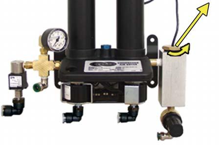
15 On BACK of dryer: Verify that the red orifice plug is still installed where shown Install the two (2) purge mufflers (shipped loose) Verify that the dryer is powered OFF Plug the power cord into a VAC, 1 phase, 50 / 60 Hz power outlet. (HBL9965C Compatible) Remove the Top Cover from the dryer. Page 15 of 88
16 Verify incoming voltage measurement: Locate the Main POWER Circuit Breaker Use a Voltmeter to measure the voltage by placing the probes between the Circuit Breaker and terminal insulation so that they touch the metal contacts. If the voltage measures between VAC, skip to step If the voltage measures less than 210 VAC, continue to the next steps to engage the Boost Transformer Engage the Boost Transformer: Unplug the power cord from the power outlet. Page 16 of 88
17 Locate the Main Power Lead quick disconnects in the top section of the dryer Unplug the Main Power Lead quick disconnects Plug both of the Boost Transformer Lead connectors into the Main Power Lead connectors. The incoming power wiring should now look like this: Page 17 of 88
18 Plug the power cord back into the power outlet Reinstall the Top Cover back onto the dryer Turn the dryer power ON. NOTE: Both system compressors and heatless dryers will start, creating air flow through the red outlet pressure orifice Set the System Pressures: System 1 & System 2 are adjusted and set independently. Perform the following steps for System 1 (left) and then repeat the steps for System 2 (right). With Compressor running: Pull the Capacity Control Valve knob out. Page 18 of 88

19 Turn the knob until the reading on the pressure gauge is 50 PSI Push the knob in to lock Let the dryer run until the Humidity drops under 2% on both System 1 and System 2 (may take up to 15 minutes). NOTE: Press RESET if either System goes into SHUTDOWN Turn the dryer OFF. Page 19 of 88
20 Connect the air supply line to the dryer. CAUTION: Be careful when removing outlet plug. System may be pressurized. PUREGAS recommends using Installation Kit P to connect your dryer to the air supply line (See section 11.6 for detail) Turn the dryer ON Set the Static Pressure: Pull Static Pressure Regulator knob out Turn knob until the reading on the pressure gauge is 17 PSI Push knob in to lock. Page 20 of 88
21 Set the Outlet Pressure: When the Unit Screen ( ) appears on the display, press the HOLD Button on the Front Panel to freeze that screen Pull the Outlet Pressure Regulator knob out Turn knob until Outlet Pressure (OUTP) reading is at the desired setting Push knob in to lock Check for air leaks: NOTE: This is a general procedure that can be applied to any fitting or hose that has air pressure in it. DO NOT SOAP TEST THE HUMITTER FITTING. DAMAGE TO THE HUMITTER MAY OCCUR. With Compressor(s) NOT running: Listen for any hissing sounds which may indicate a fitting or hose air leak. Page 21 of 88

22 With Compressor(s) running: Use a 1-inch paint brush to dab soapy water on the air fitting or hose connection to be tested. If air bubbles appear at the connection, this indicates that air is leaking from the connection. If any leaks are detected, take steps to seal them off (as necessary): Tighten the fitting Re-connect the hose end Replace the fitting / hose / component Re-install the front panel REGISTER YOUR DRYER. See section 7. for details. Page 22 of 88
23 6.6 Installation Checklist No shipping damage was detected. Dryer location meets the following requirements: o Well ventilated o Free from abrasive dust or chemicals o Ambient temperature is between 40 and 85 F (optimal) Operating Power is between VAC. Shipping block removed from compressor trays. System Pressures are set to 50 PSI. Static Pressure is set to 17 PSI. No air leaks are present in the system. No alarms are present on the Display Panel. Page 23 of 88
24 7. Registering Your Dryer Please take a moment to register your PUREGAS P6500W Air Dryer. Registering is necessary to activate the Limited Warranty on your product. Once you register, you are eligible to receive free technical support, as well as updates concerning your PUREGAS products. Register Online at Or by Phone (option 2) Have the following information available: Model #: P6500W Serial #: Company Name: Location Name: Shipping Address: City: State: Zip Code: Contact Name: Phone #: ( ) - ext. Page 24 of 88
25 8. Operating Your Dryer 8.1 Safety & Warning Information WARNING! Extreme care should be exercised to avoid contact with live electrical circuits. Many procedures performed during installation, operation, testing, and maintenance of this air dryer require the equipment to be running, creating a situation for potential electrical shock. It is highly recommended that you remove all jewelry before performing any procedures. WARNING! Internal surfaces may be hot. Use care when coming into contact with internal components as there is a potential for some of these components to become hot when in operation or standby. WARNING! High Noise. Puregas air dryers are meant to be installed in an unattended area. CAUTION! Observe precautions for handling Electrostatic Sensitive Devices. IMPORTANT! Performing procedures not described in this User s Guide or installing components not supplied by PUREGAS is NOT RECOMMENDED AND MAY VOID THE WARRANTY. Page 25 of 88
. 8.")

26 8.2 Connecting Air Lines to the Dryer Connect the air supply line to the dryer Outlet Pressure port (adjustable between 0-15 PSI) CAUTION: Be careful when removing outlet plugs. System may be pressurized. PUREGAS recommends using Installation Kit P to connect your air dryer to the air supply line (See section 11.6 for detail). 8.3 Powering the Dryer ON & OFF POWER Circuit Breaker - Controls the main power to the dryer. This must be in the ON position for either System 1 or System 2 to be powered ON SYSTEM 1 Circuit Breaker - Turns System 1 ON/OFF SYSTEM 2 Circuit Breaker - Turns System 2 ON/OFF. Page 26 of 88
.")
27 8.4 Using the Front Panel Display CAUTION! The Display Screen is covered by a clear protective layer that guards against Electrostatic Discharge (ESD). DO NOT REMOVE THIS LAYER RESET Button Clears an alarm and allows the system to continue operating MODE Button Changes the System Cycle Mode: 24 HOUR CYCLE Cycles between System 1 & System 2 every 24 hours (when the CYCLE TIME on the Unit Screen reaches 00:00). One system will be Online (ON) and the other in STANDBY. BOTH Runs both System 1 and System 2 simultaneously. SYSTEM 1 ONLY Runs only System 1 and leaves System 2 in Standby. SYSTEM 2 ONLY - Runs only System 2 and leaves System 1 in Standby HOLD Button Freezes the current information screen on the display. When pressed again, it will allow the information screens to begin cycling again. Page 27 of 88
28 8.4.4 Arrow Buttons Used to access, navigate, and change values in the Set Point Adjust screens Display Screen - Shows the current dryer readings. Will cycle between the following information screens (unless the HOLD button has been pressed): Tank Screen TANK Air Tank pressure - fluctuates between PSI. OUTP Outlet Pressure regulated by the Outlet Pressure Regulator FLOW Air Flow Rate CYCLE TIME Represents the progress of the air dryer through a 24 hour cycle. Range from 00:00 23: Compress Screen COMPRESS Temperature of the lower compressor compartment. CABINET Temperature of the upper circuit board compartment. Page 28 of 88
29 System Screens (System* = System 1 or System 2) SYSTEM* - Running Status of System*: ON System* is Online in the dryer cycle mode. STANDBY System* is not Online in the dryer cycle mode. SHUTDOWN System* has been shutdown as a result of either a Humidity, High Compressor Temperature, or High Cabinet Temperature alarm. HUMIDITY Humidity level of System*. LAST RUN How many minutes the System* compressor ran during the last Air Tank pressurization cycle. TOTAL HR How many hours the System* compressor has run since the last Total Hour Reset System Cycle Mode Screen Displays the current System Cycle Mode setting: 24 HOUR CYCLE Cycles between System 1 & System 2 every 24 hours (when the CYCLE TIME on the Unit Screen reaches 00:00). Puts one system Online and the other in Standby. BOTH Runs both System 1 and System 2 simultaneously. SYSTEM 1 ONLY Runs only System 1 and leaves System 2 in Standby. SYSTEM 2 ONLY - Runs only System 2 and leaves System 1 in Standby. Page 29 of 88
30 8.5 Identifying Dryer Alarms High Outlet Pressure Alarm - Occurs when the Outlet Pressure (OUTP) rises above the alarm set point for more than one (1) minute. (Default setting is 12.0 PSI) See section 13.5 for troubleshooting information Low Outlet Pressure Alarm Occurs when the Outlet Pressure (OUTP) drops below the alarm set point for more than one (1) minute. (Default setting is 6.5 PSI) See section 13.7 for troubleshooting information High Flow Alarm Occurs when the Flow Rate (FLOW) rises above the alarm set point for more than one (1) minute. (Default setting is 4500 SCFD) See section 13.9 for troubleshooting information High Compressor Temperature Alarm Occurs when the temperature in the lower compressor compartment rises above 140 F for more than one (1) minute. If this alarm is present for one (1) minute or more, the air dryer will go into SHUTDOWN mode to protect against damage due to overheating. See section for troubleshooting information. Page 30 of 88
31 8.5.5 High Cabinet Temperature Alarm - Occurs when the temperature in the upper circuit board compartment rises above 140 F for more than one (1) minute. If this alarm is present for one (1) minute or more, the air dryer will go into SHUTDOWN mode to protect against damage due to overheating. See section for troubleshooting information High Humidity Alarm Occurs when the Humidity level rises above the alarm set point for more than one (1) minute. (Default setting is 10.0%) If this alarm is present for one (1) minute or more, the air dryer will go into SHUTDOWN mode to prevent saturated air from being delivered to the supply line. See section for troubleshooting information Compressor Excessive Run Time Alarm Occurs when the compressor takes longer to pressurize the air tank than the set point for the alarm. (Default setting is 3:00 minutes) See section for troubleshooting information Compressor Total Hour Alarm Occurs when the compressor has reached an 8,000 hour maintenance interval. Perform the next required maintenance. See section 10.3 for maintenance information. Page 31 of 88
32 8.6 Adjusting & Resetting Dryer Set Points Dryer Set Points are simply limits programmed for a specific reading. Once this limit is reached (or exceeded) this results in an alarm for that reading. Each of these set points is factory programmed with a default value based on typical usage of the air dryer. Many of the set points for dryer alarms can be modified to levels more closely based upon your specific application. Reference Appendix Section 14.2 for Limits and Defaults. Press the Up ( ) Arrow Button to access the Set Point Adjust screens. Press the Up ( ) & Down ( ) Arrow Buttons to navigate through the available Set Point Adjust screens. To change a specific Set Point: High Flow Alarm Set Point (default setting is 4500 SCFD) Press the Right ( ) Arrow Button to access the Change Value Screen Press the Right ( ) & Left ( ) Arrow Buttons to move the underscore beneath the digit to change Press the Up ( ) & Down ( ) Arrow Buttons to change the value of the selected digit Press the Right ( ) Arrow Button until the underscore disappears. This will lock in the new setting value. Page 32 of 88
33 8.6.2 High Outlet Pressure Alarm Set Point (default setting is 12 PSI) Press the Right ( ) Arrow Button to access the Change Value Screen Press the Right ( ) & Left ( ) Arrow Buttons to move the underscore beneath the digit to change Press the Up ( ) & Down ( ) Arrow Buttons to change the value of the selected digit Press the Right ( ) Arrow Button until the underscore disappears. This will lock in the new setting value Low Outlet Pressure Alarm Set Point (default setting is 6.5 PSI) Press the Right ( ) Arrow Button to access the Change Value Screen Press the Right ( ) & Left ( ) Arrow Buttons to move the underscore beneath the digit to change Press the Up ( ) & Down ( ) Arrow Buttons to change the value of the selected digit Press the Right ( ) Arrow Button until the underscore disappears. This will lock in the new setting value. Page 33 of 88
34 8.6.4 High Humidity Alarm Set Point (default setting is 10.0%) Press the Right ( ) Arrow Button to access the Change Value Screen Press the Right ( ) & Left ( ) Arrow Buttons to move the underscore beneath the digit to change Press the Up ( ) & Down ( ) Arrow Buttons to change the value of the selected digit Press the Right ( ) Arrow Button until the underscore disappears. This will lock in the new setting value Excessive Compressor Run Time Alarm Set Point (default setting is 3:00 minutes) Press the Right ( ) Arrow Button to access the Change Value Screen Press the Right ( ) & Left ( ) Arrow Buttons to move the underscore beneath the digit to change Press the Up ( ) & Down ( ) Arrow Buttons to change the value of the selected digit Press the Right ( ) Arrow Button until the underscore disappears. This will lock in the new setting value. Page 34 of 88
35 8.6.6 Cycle Time Set Point The Cycle Time represents the progress of the air dryer through a 24 hour cycle (00:00 23:59). The air dryer will cycle when the timer reaches 00:00. Setting the timer to the current clock time will cause the dryer to cycle at midnight each day. Setting the timer to 00:00 when the current clock time is 8:00 am will cause the dryer to cycle at exactly 8:00 am each day Press the Right ( ) Arrow Button to access the Change Value Screen Press the Right ( ) & Left ( ) Arrow Buttons to move the underscore beneath the digit to change Press the Up ( ) & Down ( ) Arrow Buttons to change the value of the selected digit Press the Right ( ) Arrow Button until the underscore disappears. This will lock in the new setting value System 1 Compressor Total Hour Reset Press and Hold the Left ( ) & Right ( ) Arrow Buttons at the same time until the value resets to zero (0). Page 35 of 88
36 8.6.8 System 2 Compressor Total Hour Reset Press and Hold the Left ( ) & Right ( ) Arrow Buttons at the same time until the value resets to zero (0) Reset to Factory Values Press and Hold the Left ( ) & Right ( ) Arrow Buttons at the same time until screen flickers. This will signify the default values have reset Alarm Delays Set Point The Alarm Delay allows an alarm condition to be present for up to one (1) minute before signaling the alarm. This allows the dryer to come out of the alarm condition on its own without signaling an alarm. ON (default) waits one (1) minute before signaling alarms OFF signals alarms immediately Press the Right ( ) Arrow Button to change the value Pressure Gauge This is an information screen only and will not time-out, returning to the cycling information screens. It also masks air dryer alarms while in use. This screen can be used during air dryer troubleshooting. Page 36 of 88
 8.8.2 Connect the external wire pair to the Common Alarm terminals. NOTE: There are two (2) redundant terminal blocks allowing multiple connections. 8.8.3 Reinstall Top Cover.")
37 8.7 Opening Panels Removing Top Cover Depress the latches and pull the Top Cover off Removing Front Panel Depress the latches and pull the Front Panel out. 8.8 Connecting to Common Alarm Terminals Remove Top Cover (see section ) Connect the external wire pair to the Common Alarm terminals. NOTE: There are two (2) redundant terminal blocks allowing multiple connections Reinstall Top Cover. Page 37 of 88
 8.10.2 Pull the ring handle on the Safety Relief Valve until all air pressure is released. 8.10.3 To prevent pressure from building back up, power the dryer OFF (See section 8.")
38 8.9 Connecting to Discrete Alarm Terminals Connect the external wire pair to the specific alarm terminal Depressurizing the Dryer Remove Front Panel (see section ) Pull the ring handle on the Safety Relief Valve until all air pressure is released To prevent pressure from building back up, power the dryer OFF (See section 8.3 for detail) Reinstall Front Panel. Page 38 of 88
39 8.11 Setting the System Pressure System 1 & System 2 are adjusted and set independently. With Compressor running: Remove Front Panel (see section ) Pull the Capacity Control Valve knob out Turn the knob until the reading on the Pressure Gauge is 50 PSI Push the knob in to lock Reinstall Front Panel. Page 39 of 88
 8.13.2 When the Unit Screen (8.4.5.1 appears on the display, press the HOLD Button on the Front Panel to freeze that screen.")
40 8.12 Setting the Static Pressure Remove Front Panel (see section ) Pull Static Pressure Regulator knob out Turn knob until the reading on the pressure gauge is 17 PSI Push knob in to lock Reinstall Front Panel Setting the Outlet Pressure Remove Front Panel (see section ) When the Unit Screen ( appears on the display, press the HOLD Button on the Front Panel to freeze that screen. Page 40 of 88
41 Pull the Outlet Pressure Regulator knob out Turn knob until Outlet Pressure (OUTP) reading is at the desired setting Push knob in to lock Reinstall Front Panel Engaging the Boost Transformer Turn the dryer OFF Unplug the power cord from the power outlet Remove Top Cover (see section ) Page 41 of 88


42 Locate the Main Power Lead quick disconnects in the top section of the dryer Unplug the Main Power Lead quick disconnects Plug both of the Boost Transformer Lead connectors into the Main Power Lead connectors. The incoming power wiring should now look like this: Page 42 of 88

43 Reinstall the Top Cover back the dryer Plug the power cord back into the power outlet Turn the dryer ON. Page 43 of 88
44 9. Testing Your Dryer NOTE: Many of the procedures described in this section will be easier with both System 1 and System 2 operating. It is recommended that you change the System Cycle Mode to BOTH for the following procedures (see section for details on changing modes). 9.1 Safety & Warning Information WARNING! Extreme care should be exercised to avoid contact with live electrical circuits. Many procedures performed during installation, operation, testing, and maintenance of this air dryer require the equipment to be running, creating a situation for potential electrical shock. It is highly recommended that you remove all jewelry before performing any procedures. WARNING! Internal surfaces may be hot. Use care when coming into contact with internal components as there is a potential for some of these components to become hot when in operation or standby. WARNING! High Noise. Puregas air dryers are meant to be installed in an unattended area. CAUTION! Observe precautions for handling Electrostatic Sensitive Devices. CAUTION! Depressurizing the air dryer may be necessary before performing certain procedures. NEVER remove pressure sensing tubes from the control board without depressurizing the air dryer first, or damage to the control board will occur. Page 44 of 88


45 9.2 Measuring Compressor Amp Draw WARNING! Internal surfaces may be hot. Use care when coming into contact with internal components as there is a potential for some these components to become hot when in operation or standby. With the Compressor running: Remove Front Panel (see section ) Locate the hot lead wire going to the Compressor you will be measuring: System 1 = Wire #1 System 2 = Wire # Use an Amp Meter to measure the running amps. With the compressor running, the running amps should measure 4.0 amps or below Reinstall Front Panel. If the compressor measures over 4.0 running amps, see section for troubleshooting information. Page 45 of 88


46 9.3 Measuring Voltage to Compressor WARNING! Extreme care should be exercised to avoid contact with live electrical circuits. It is highly recommended that you remove all jewelry before performing any procedures Remove Front Panel (see section ) With the Compressor running: Locate the power lead wires to the compressor to be measured Use a Voltmeter to measure the voltage between the Hot and Neutral wires by placing the probes in the openings in the power connector: System 1 = Wires #1 & #2 System 2 = Wires #8 & #7 The voltage should measure VAC Reinstall Front Panel. Page 46 of 88
47 9.4 Measuring Incoming Voltage WARNING! Extreme care should be exercised to avoid contact with live electrical circuits. It is highly recommended that you remove all jewelry before performing any procedures Remove Top Cover (see section ) Locate the Main POWER Circuit Breaker Place Voltmeter probes between the Circuit Breaker and terminal insulation so that they touch the metal contacts. The voltage should measure VAC Reinstall Top Cover. If the incoming voltage measures less than 210 VAC, it is necessary to engage the Boost Transformer in order to increase the voltage to the desired range of VAC. See section 8.14 for procedure. Page 47 of 88


48 9.5 Measuring Voltages at Solid State Relay Remove Top Cover (see section ) Locate the Solid State Relay for the system you will be testing: Left System 1 Right System 2 (System* = System 1 or System 2) With the System* Compressor running: Use a Voltmeter to measure across the AC terminals. Should measure 0 VAC Use a Voltmeter to measure across the DC terminals. Should measure 12 VDC. With the System* Compressor NOT running: Use a Voltmeter to measure across the AC terminals. Should measure VAC Use a Voltmeter to measure across the DC terminals. Should measure 0 VDC Reinstall Top Cover. If any of the voltage measurements are different than indicated above, the Solid State Relay is defective and should be replaced. See sections 11.1 for part detail and 11.7 for ordering information. Page 48 of 88
 9.6.2 Disconnect the purge tubes from the System* Heatless Dryer. 9.6.3 Place your hand beneath the purge fittings to feel for purging air.")

49 9.6 Testing Consistent Heatless Dryer Cycling With the System* Compressor running (System* = System 1 or System 2): Remove Front Panel (see section ) Disconnect the purge tubes from the System* Heatless Dryer Place your hand beneath the purge fittings to feel for purging air. Air should: Purge from Tower 1 side Purge from Tower 2 side 30 Seconds later Purge from Tower 1 side 30 Seconds later and so on Re-connect the purge tubes to the Heatless Dryer Reinstall Front Panel. If the Heatless Dryer is not cycling consistently as described, see section for troubleshooting information. Page 49 of 88


50 9.7 Testing Unloader Valve With the System* Compressor running (System* = System 1 or System 2): Remove Front Panel (see section ) Disconnect the unloader tube from the System* Unloader Valve Place your hand beneath the Unloader Valve fitting to feel for air flow. Air should NOT flow from this fitting continuously. Air should only be released in a short burst when the System* compressor shuts off Re-connect the unloader tube to the Unloader Valve Reinstall Front Panel. If air flows from this valve continuously the Unloader Valve is defective and should be replaced. See sections 11.3 for part detail and 11.7 for ordering information. Page 50 of 88
 sets of terminals (from left-to-right): 106VDC Left solenoid IN Incoming power 106VDC Right solenoid 9.8.")
51 9.8 Measuring Heatless Dryer Solenoid Voltage With the System* Compressor running (System* = System 1 or System 2): Remove Front Panel (see section ) Locate the Heatless Dryer Cycle Timer. The timer has three (3) sets of terminals (from left-to-right): 106VDC Left solenoid IN Incoming power 106VDC Right solenoid Use a Voltmeter to measure the DC voltage across each set of 106VDC terminals. Continue to measure for up to 45 seconds if no voltage is initially measured. The voltage should measure 106 Volts DC Reinstall Front Panel. If the voltage does not measure 106 Volts DC, this is an indication that the Cycle Timer is defective and should be replaced. See sections 11.3 for part detail and 11.7 for ordering information. Page 51 of 88
 Replace defective fan (see sections 11.2 for part detail and 11.")
52 9.9 Testing Precooler Fans Remove Front Panel (see section ) Place your hand above the Precooler Fan(s) to feel for air being blown upwards Reinstall Front panel. If either fan is not blowing air upwards as described: Check for loose wiring. Refer to the Wiring Diagram (section 14.1 ) Replace defective fan (see sections 11.2 for part detail and 11.7 for ordering information) Testing Safety Relief Valve Remove Front Panel (see section ) Pull the ring handle on the Safety Relief Valve to verify air pressure is released Release ring handle and verify that no air is leaking from the valve Reinstall Front Panel. If the Safety Relief Valve fails either test described, it must be replaced. See sections 11.2 for part detail and 11.7 for ordering information. Page 52 of 88
 appears on the display, press the HOLD Button on the Front Panel to freeze that screen. With Compressor(s) running: 9.11.")
53 9.11 Testing Compressor ON/OFF Cycling Remove Front Panel (see section ) When the Unit Screen ( ) appears on the display, press the HOLD Button on the Front Panel to freeze that screen. With Compressor(s) running: Verify the compressor(s) shuts down when the tank pressure (TANK) reaches 50.0 PSI. If the tank pressure (TANK) fails to reach 50 PSI, see section for troubleshooting information. With Compressor(s) NOT running: Pull the ring handle on the Safety Relief Valve to release air pressure from the air tank Verify the compressor(s) turns on when the tank pressure (TANK) falls to 20.0 PSI Reinstall Front Panel. If the Compressor Cycling fails either test described, it indicates a problem with the Control Board which may need to be replaced. See sections 11.1 for part detail and 11.7 for ordering information. Page 53 of 88
 9.")
54 9.12 Testing Compressor Excessive Run Time Alarms NOTE: All testing values are based on default Air Dryer settings, if settings have been changed, adjust testing values accordingly. Reference the Appendix Section 14.2 for Limits and Defaults. NOTE: For this test, allow the Display Screen to cycle through the information screens Remove Front Panel (see section ) Start timing when the compressor(s) turns on Pull the ring handle on the Safety Relief Valve (when necessary) to keep the Tank Pressure (TANK) from reaching 50 PSI. This prevents the compressor(s) from shutting down. When the compressor(s) runs for 3:00 minutes (unless adjusted to a different Set Point by the user), a Compressor Excessive Run Time (LAST RUN) alarm should appear on one or both of the System screens Press the RESET Button to clear the alarm Reinstall Front Panel. If you are unable to create a Compressor Excessive Run Time (LAST RUN) alarm as described, see section for troubleshooting information. Page 54 of 88
. Test one System at a time (System* = System 1 or System 2). 9.13.")
 appears on the display, press the HOLD Button on the Front Panel to freeze that screen. 9.13.")
55 9.13 Testing Humidity Alarm and System Shutdown NOTE: For this test, make sure the air dryer is operating in BOTH Cycle Mode (see section for details on changing Cycle Mode). Test one System at a time (System* = System 1 or System 2) Remove Front Panel (see section ) Turn the System* Circuit Breaker OFF When the System* Screen ( ) appears on the display, press the HOLD Button on the Front Panel to freeze that screen Verify the System* pressure is zero (0). Page 55 of 88

56 Unscrew and remove the Humitter from the Humidity Block Allow the Humidity reading to rise over 10.0% After three (3) minutes, verify that a Humidity Alarm appears and System* goes into SHUTDOWN mode Replace the Humitter into the Humidity Block Reinstall Front Panel Turn the System* Circuit Breaker ON Press the RESET Button to clear the alarm. If you are unable to create a Humidity / Shutdown alarm as described, see section for troubleshooting information. Page 56 of 88
57 9.14 Testing High Outlet Pressure Alarm Remove Front Panel (see section ) When the Unit Screen ( ) appears on the display, press the HOLD Button on the Front Panel to freeze that screen Make a note of the current Outlet Pressure (OUTP) reading. With Compressor(s) running: Pull the Outlet Pressure Regulator knob out Turn knob clockwise until Outlet Pressure (OUTP) reading climbs over 12.0 PSI. After one (1) minute, the High Pressure Alarm should appear on the display. Page 57 of 88
58 Turn Outlet Pressure Regulator knob counterclockwise until Outlet Pressure (OUTP) reading lowers to the reading recorded in step Push knob in to lock Press the RESET Button to clear the alarm Reinstall Front Panel. If you are unable to create a High Outlet Pressure Alarm as described, see section 13.6 for troubleshooting information Testing Low Outlet Pressure Alarm Remove Front Panel (see section ) When the Unit Screen ( ) appears on the display, press the HOLD Button on the Front Panel to freeze that screen Make a note of the current Outlet Pressure (OUTP) reading. Page 58 of 88
 minute, the Low Pressure Alarm should appear on the display. 9.15.")
59 With Compressor(s) running: Pull the Outlet Pressure Regulator knob out Turn knob counterclockwise until Outlet Pressure (OUTP) reading drops below 6.5 PSI. After one (1) minute, the Low Pressure Alarm should appear on the display Turn Outlet Pressure Regulator knob clockwise until Outlet Pressure (OUTP) reading raises to the reading recorded in step Push knob in to lock Press the RESET Button to clear the alarm Reinstall Front Panel. If you are unable to create a Low Outlet Pressure Alarm as described, see section 13.8 for troubleshooting information. Page 59 of 88
60 9.16 Testing Air Fittings & Hoses for Leaks NOTE: This is a general procedure that can be applied to any fitting or hose that has air pressure in it. DO NOT SOAP TEST THE HUMITTER FITTING. DAMAGE TO THE HUMITTER MAY OCCUR. With Compressor(s) NOT running: Listen for any hissing sounds which may indicate a fitting or hose air leak. With Compressor(s) running: Use a 1-inch paint brush to dab soapy water on the air fitting or hose connection to be tested. If air bubbles appear at the connection, this indicates that air is leaking from the connection. If any leaks are detected, take steps to seal them off (as necessary): Tighten the fitting Re-connect the hose end Replace the fitting / hose / component Page 60 of 88
61 10. Maintaining Your Dryer In order to ensure that your P6500W Air Dryer continues to operate efficiently and reliably, PUREGAS recommends performing the following maintenance procedures at the specified Six Month / 8,000 Hour / and 16,000 Hour intervals. It is also recommended that you print out the included Six Month Maintenance (section 10.2 ) and 8,000 & 16,000 Hour Maintenance (section 10.3 ) log sheets and record all completed maintenance for historical tracking and reference purposes. The log sheets include a Section reference column which indicates the User s Guide section containing the information about the specific procedure. Please refer to these sections for detailed procedural information. NOTE: When operating at higher ambient temperatures, it is recommended that maintenance be performed more frequently. NOTE: After 16,000 hours of run time, PUREGAS recommends sending in your compressors and heatless dryers for a complete and comprehensive rebuild by our Service Department technicians. See sections 12.1 and 12.2 for information on services and contacting PUREGAS Safety & Warning Information WARNING! Extreme care should be exercised to avoid contact with live electrical circuits. Many procedures performed during installation, operation, testing, and maintenance of this air dryer require the equipment to be running, creating a situation for potential electrical shock. It is highly recommended that you remove all jewelry before performing any procedures. Page 61 of 88
62 WARNING! Internal surfaces may be hot. Use care when coming into contact with internal components as there is a potential for some of these components to become hot when in operation or standby. CAUTION! SHUT DOWN IMMEDIATELY FOR REPAIRS if the air compressor(s) shows any evidence of overheating or presents excessive noise. CAUTION! Depressurizing the air dryer may be necessary before performing certain procedures. NEVER remove pressure sensing tubes from the Control Board without depressurizing the air dryer first, or damage to the Control Board will occur. WARNING! High Noise. Puregas air dryers are meant to be installed in an unattended area. CAUTION! Observe precautions for handling Electrostatic Sensitive Devices. IMPORTANT! After performing any maintenance, always soap test pressure fittings to check for air leaks. Also, check for any loose or disconnected wiring. Page 62 of 88
63 10.2 Six Month Maintenance MODEL: P6500W LOCATION NAME: SERIAL NUMBER: ADDRESS: DATE INSTALLED: Maintenance Interval (Months) Procedure Section Install Six Month Maintenance Kit P Read & Record Flow Rate (FLOW) Measure & Record Compressor 1 Amp Draw 9.2 Measure & Record Compressor 2 Amp Draw 9.2 Measure & Record Incoming Voltage (must be VAC) 9.4 Test High & Low Outlet Pressure Alarms 9.14 & 9.15 Set System Pressure (50 PSI) 8.11 Set Static Pressure (17 PSI) 8.12 Set Outlet Pressure 8.13 Test Consistent Heatless Dryer Cycling 9.6 Test Precooler Fans 9.9 Test Safety Relief Valve 9.10 Test Compressor ON/OFF Cycling 9.11 Test Compressor Excessive Run Time Alarms 9.12 Test Humidity Alarm & System Shutdown 9.13 Test Air Fittings for Leaks 9.16 Clean Precooler Coils Visually Inspect Inside & Outside of Unit for Loose Wiring or Hardware Maintenance Performed by: Date of Maintenance: NOTE: COPY OR PRINT THIS PAGE AND KEEP IT WITH THE AIR DRYER Page 63 of 88
64 10.3 8,000 & 16,000 Hour Maintenance Under typical operating conditions: 8,000 hours of run time will occur between one (1) and two (2) years of use. 16,000 hours of run time will occur between two (2) and three (3) years of use. This will be identified by a Compressor Total Hour Alarm on the display for either System 1 or System 2 (section ). MODEL: P6500W LOCATION NAME: SERIAL NUMBER: ADDRESS: DATE INSTALLED: Maintenance Interval (Hours) Procedure Section 8,000 16,000 24,000 32,000 40,000 Install 8,000 Hour Maintenance Kit P Install 16,000 Hour Maintenance Kit P Read & Record Flow Rate (FLOW) Measure & Record Compressor 1 Amp Draw 9.2 Measure & Record Compressor 2 Amp Draw 9.2 Set System Pressure (50 PSI) 8.11 Set Static Pressure (17 PSI) 8.12 Set Outlet Pressure 8.13 Test Consistent Heatless Dryer Cycling 9.6 Test Compressor ON/OFF Cycling 9.11 Test Air Fittings for Leaks 9.16 Reset Total Hour Readings to Zero & System 1 & System Visually Inspect Inside & Outside of Unit for Loose Wiring or Hardware Maintenance Performed by: Date of Maintenance: NOTE: COPY OR PRINT THIS PAGE AND KEEP IT WITH THE AIR DRYER Page 64 of 88
")
 Discrete Alarm Relay Board P010525 1 Power Supply Board P010199 1 (1) Cabinet")
65 11. Replacement Parts & Accessories 11.1 Top Section Parts Description Part Number Quantity Recommend Spare Solid State Relay P (1) Terminal Block P Front Panel Display Assembly P LCD Display Only P Circuit Breaker P (1) Discrete Alarm Relay Board P Power Supply Board P (1) Cabinet Temperature Sensor P Control Board (w/ Eprom) P (1) Page 65 of 88

 P011339 1 Static Pressure Regulator")
")
66 11.2 Middle Section Parts Description Part Number Quantity Recommend Spare Boost Transformer P Heatless Dryer Assembly See section11.3 for detail. Pressure Gauge (0-30 PSI) P Static Pressure Regulator P (1) Adapter Plate 2 Flow Block 1 Air Tank 1 Safety Relief Valve P Fan Guard 2 Precooler Fan P (1) Outlet Pressure Regulator P (1) Page 66 of 88


 Capacity")
67 11.3 Heatless Dryer Assembly Parts Description Part Number Quantity Recommend Spare Heatless Dryer P Pressure Gauge P Solenoid Valve In Kit P See section 11.6 for detail. Unloader Valve P Cycle Timer P Desiccant Chamber P Humitter P (1) Capacity Control Valve P (1) Page 67 of 88

 *Assembled for quick, easy installation.")
68 11.4 Lower Section Parts Description Part Number Quantity Recommend Spare Compressor Temperature Sensor P Muffler 3/8 mpt In Kit P See section 11.6 for detail. Air Compressor Assembly* Left Side Right Side P P (1) (1) Compressor ONLY P (1) Spacer 8 Precooler P Discharge Hose P Capacitor 2 Vibration Mount P (8) *Assembled for quick, easy installation. Includes: compressor, bracket, mounting plate, vibration mounts, spacers, fittings, electrical connectors, and air intake filter/muffler. Page 68 of 88

69 11.5 Frame Section Parts Description Part Number Quantity Recommend Spare Top Cover 1 Front Panel 1 Air Intake Filter In Kit P See section 11.6 for detail. Purge Muffler In Kit P See section 11.6 for detail. Trigger Latch 6 Page 69 of 88


70 11.6 Accessories for Your Dryer Description Installation Kit Includes fittings required to connect to 3/4 flexible hose. Part Number P Recommend Spare Six Month Maintenance Kit Includes air intake filter, compressor mufflers, and purge mufflers. 8,000 Hour Maintenance Kit Includes heatless dryer maintenance kits and compressor maintenance kits. 16,000 Hour Maintenance Kit Includes heatless dryer maintenance kits, compressor maintenance kits, and humitters. Monitoring Interface Allows the dryer to be fully monitored by PUREGAS monitoring systems. P (2) P (1) P (1) PVDW30 Page 70 of 88
P4200W2 Series Air Dryer
 P4200W2 Series Air Dryer User s Guide Models covered: P4200W2 P4200W2LP P4202W2 P4202W2LP P4202W2H 1. Welcome & Congratulations Congratulations on your purchase of a new PUREGAS P4200W2 Series Air Dryer!
P4200PM / P5000PM Remote Air Dryer User s Guide
 P4200PM / P5000PM Remote Air Dryer User s Guide 1. Welcome & Congratulations Congratulations on your purchase of a new PUREGAS P4200PM / P5000PM Air Dryer! We here at PUREGAS are very proud of our products
P550W Series Air Dryers
 P550W Series Air Dryers User s Guide Models covered: P550W P550WH P550WLP P552W P552WH P552WLP 1. Welcome & Congratulations Congratulations on your purchase of a new PUREGAS P550W Series Air Dryer! We
Installation Guide. P1500W Series Air Dryer
 P1500W Series Air Dryer Installation Guide This guide covers basic air dryer installation and setup only. Once installation is complete, please refer to the P1500W Series User s Guide for more advanced
P10KW / P15KW Air Dryer Installation Guide
 P10KW / P15KW Air Dryer Installation Guide This guide covers basic air dryer installation and setup only. Once installation is complete, please refer to the P10KW / P15KW User s Guide for more advanced
VSA Series Air Dryer. User s Guide
 VSA Series Air Dryer User s Guide Models covered: VSA1 VSA2 VSA3 VSA4 1. Welcome & Congratulations Congratulations on your purchase of a new PUREGAS VSA SERIES AIR DRYER! We here at PUREGAS are very proud
MDH Series Air Dryer. User s Guide
 MDH Series Air Dryer User s Guide Models covered: MDH1 MDH2 MDH3 MDH4 MDH5 MDH6 1. Welcome & Congratulations Congratulations on your purchase of a new PUREGAS MDH SERIES AIR DRYER! We here at PUREGAS
P08033W Air Dryer Cycling Module User s Guide
 P08033W Air Dryer Cycling Module User s Guide 1. Welcome & Congratulations Congratulations on your purchase of a new PUREGAS P08033W Air Dryer Cycling Module! We here at PUREGAS are very proud of our
OPERATING MANUAL MODEL AIR 1500TM AIR DRYER
 OPERATING MANUAL MODEL AIR 500TM AIR DRYER Puregas, LLC 226-A Commerce St. Tel: 800-52-535 Broomfield, Colorado Fax: 303-657-2205 P/N P0255 REV A, 02/9/4 TABLE OF CONTENTS.0 GENERAL... 3 2.0 SPECIFICATIONS...
MODEL MW200 MODEL MW600 AIR DRYER
 OPERATING MANUAL MODEL MW200 MODEL MW600 AIR DRYER Mail Address: 226A Commerce St. Tel: 303-465-3063 Broomfield, CO 80020 Fax: 303-465-9294 TABLE OF CONTENTS 1.0 GENERAL...3 2.0 SPECIFICATIONS...3 3.0
WILKERSON MODELS DE3, DE4 AND DE5 COMPACT HEATLESS AIR DRYERS
 INSTRUCTION MANUAL FOR WILKERSON MODELS DE3, DE4 AND DE5 COMPACT HEATLESS AIR DRYERS DE3 - DE5 OPERATIONS GENERAL This instruction manual covers the installation, operation, maintenance and troubleshooting
OPERATING INSTRUCTIONS AND PARTS LIST FOR. P05860-H2 (heatless) Nitrogen Bottle Replacement Unit
 Nitrogen Bottle Replacement Unit") OPERATING INSTRUCTIONS AND PARTS LIST FOR P05860-H2 (heatless) Nitrogen Bottle Replacement Unit Made in USA P09317F1 rev C PREFACE This instruction manual is for the benefit of our customers. It is intended
OPERATING INSTRUCTIONS AND PARTS LIST FOR P05860-H2 (heatless) Nitrogen Bottle Replacement Unit Made in USA P09317F1 rev C PREFACE This instruction manual is for the benefit of our customers. It is intended
ADK MODEL Air Dehydration System INSTALLATION, OPERATING & MAINTENANCE MANUAL
 Air Dehydration System INSTALLATION, OPERATING & MAINTENANCE MANUAL 745 Clark Avenue Bristol, Connecticut 06010 TOLL FREE: 800-437-9247 (860) 585-0050 Thank you for choosing an ADK Air Dryer System by
HEATLESS DESICCANT AIR DRYER INSTRUCTION & MAINTENANCE MANUAL
 HEATLESS DESICCANT AIR DRYER INSTRUCTION & MAINTENANCE MANUAL H-Series & 203 THRU 223 SERIES ARROW PNEUMATICS, INC. REGENERATIVE DRYER DIVISION 2111 WEST 21ST STREET BROADVIEW, IL 60155 708-343-9595 708-343-1907
Portable Air Conditioner
 AC-12200E AC-12200H Portable Air Conditioner OWNER S MANUAL v1.0 Read and save these instructions. 2 A Name You Can Trust Trust should be earned and we will earn yours. Customer happiness is the focus
Easy-Lam School Budget Roll Laminator
 DO NOT DISCARD BOX! (If for any reason you need to ship your machine back and you discard your box you will be responsible for purchasing another one plus any freight charges to ship the box to you) Easy-Lam
APC BC300 Series 40kW 208/450/480V User Guide
 APC BC300 Series 40kW 208/450/480V User Guide Copyright 2002 APC Denmark ApS This manual is subject to change without notice and does not represent a commitment on the part of the vendor Thank You Thank
OWNER S MANUAL AVN SERIES RETRACTABLE NOZZLE VACUUM SEALER WITH GAS PURGE
 OWNER S MANUAL AVN SERIES RETRACTABLE NOZZLE VACUUM SEALER WITH GAS PURGE WHAT S IN THE PACKAGE? This Operation Manual. (1) Vacuum Sealer. (1) E-(unit size) Heating Element, inside the manual sheet protector.
AC-12200E Portable Air Conditioner
 AC-12200E Portable Air Conditioner OWNERS MANUAL Read and save these instructions. A Name You Can Trust Trust has to be earned and we will earn yours. Customer happiness is the focus of our business. 2
OWNER S MANUAL CAVN SERIES SELF CONTAINED RETRACTABLE NOZZLE VACUUM SEALER WITH GAS PURGE
 OWNER S MANUAL CAVN SERIES SELF CONTAINED RETRACTABLE NOZZLE VACUUM SEALER WITH GAS PURGE WHAT S IN THE PACKAGE? This Operation Manual. (1) Vacuum Sealer. (1) E-(unit size) Heating Element, inside the
DISHWASHER INSTALLATION GUIDE SPECIFICATIONS, INSTALLATION, AND MORE
 DISHWASHER INSTALLATION GUIDE SPECIFICATIONS, INSTALLATION, AND MORE COVE DISHWASHER Contents 3 Cove Dishwasher 4 Specifications 7 Door Panel 9 Installation 15 Troubleshooting Features and specifications
π H-6621 INDUSTRIAL DEHUMIDIFIER WARNINGS SPECIFICATIONS uline.com WATER REMOVAL ELECTRICAL REQUIREMENTS BUILT-IN ELECTRICAL SAFETY
 π H-6621 INDUSTRIAL DEHUMIDIFIER 1-800-295-5510 uline.com WARNINGS Plug into a grounded 3 prong outlet. Do not remove ground prong. Do not use an adapter. Do not use an extension cord if possible. Failure
User s Manual. TIGER S EYE E-Series Mark V Jockey. TIGERFLOW Systems, Inc Mint Way Dallas, Texas
 User s Manual TIGER S EYE E-Series Mark V Jockey TIGERFLOW Systems, Inc. 4034 Mint Way Dallas, Texas 75237 214-337-8780 www.tigerflow.com TABLE OF CONTENTS Introduction... 4 Sequence of Operation... 5
Owner s Manual Refrigerated Compressed Air Dryers Models F-200, 250, 300 & F350
 Owner s Manual Refrigerated Compressed Air Dryers Models F-200, 250, 300 & F350 Read carefully before attempting to assemble, install, operate or maintain the product described. Protect yourself and others
DRY AIR SYSTEMS, INC Metro Boulevard Maryland Heights, Missouri (314) fax (314)
 fax (314)") DRY AIR SYSTEMS, INC. 2655 Metro Boulevard Maryland Heights, Missouri 63043 (314) 344-1114 fax (314) 344-0677 HD SERIES DRIERS TABLE OF CONTENTS WHY AN AIR DRYER 3 WHAT IS A DESICCANT AIR DRYER 3 Desiccant
DRY AIR SYSTEMS, INC. 2655 Metro Boulevard Maryland Heights, Missouri 63043 (314) 344-1114 fax (314) 344-0677 HD SERIES DRIERS TABLE OF CONTENTS WHY AN AIR DRYER 3 WHAT IS A DESICCANT AIR DRYER 3 Desiccant
EXHAUST PURGE DESICCANT AIR DRYER INSTRUCTION & MAINTENANCE MANUAL MODEL RE-231 THROUGH RE-252
 EXHAUST PURGE DESICCANT AIR DRYER INSTRUCTION & MAINTENANCE MANUAL MODEL RE-231 THROUGH RE-252 ARROW PNEUMATICS, INC. REGENERATIVE DRYER DIVISION 500 NORTH OAKWOOD RD LAKE ZURICH, IL,60047 PHONE # (847)
Owner s Manual Refrigerated Compressed Air Dryers Model F-100
 Owner s Manual Refrigerated Compressed Air Dryers Model F-100 Read carefully before attempting to assemble, install, operate or maintain the product described. Protect yourself and others by observing
SAVE THESE INSTRUCTIONS
 U S E R M A N U A L Models: PM15F (shown) PM15P SAVE THESE INSTRUCTIONS CAUTION Federal (USA) law restricts this device to sale by or on the order of a physician. 300 Held Drive Tel: 610-262-6090 Northampton,
PMT200A SERIES DEHYDRATOR USER MANUAL. Bulletin AE01B-A NOV 05
 PMT200A SERIES DEHYDRATOR USER MANUAL Bulletin AE01B-A0523-001 Rev: B 18 NOV 05 1 TABLE OF CONTENTS SECTION 1 General Information 3 Introduction 3 Description 3 Operation 3 Alarm 3 Multiple Alarm Option
ZERO AIR GENERATOR MODEL 7000 INSTRUCTION MANUAL
 ZERO AIR GENERATOR MODEL 7000 INSTRUCTION MANUAL UNPACKING Connect the intake filter to the Air In port as shown below. Use Teflon tape on filter thread if not supplied on the fitting. POWER The ZAG is
Level Alarm Control. Blender Accessories U S E R G U I D E UGB
 www.conairgroup.com U S E R G U I D E UGB015-1007 Level Alarm Control Blender Accessories Corporate Office: 724.584.5500 Instant Access 24/7 (Parts and Service): 800.458.1960 Parts and Service: 814.437.6861
NON-CYCLING REFRIGERATED AIR/GAS DRYERS QPNC 75 to QPNC 250 OPERATOR S MANUAL
 NON-CYCLING REFRIGERATED AIR/GAS DRYERS QPNC 75 to QPNC 250 OPERATOR S MANUAL DATE OF PURCHASE: MODEL: SERIAL NO.: Record above information from nameplate. Retain this information for future reference.
WIRING DIAGRAM. This manual describes the unit features and explains how to set-up, operate and maintain these AirPac Models. COOLIT2600 COOLIT2900
 WIRING DIAGRAM This manual describes the unit features and explains how to set-up, operate and maintain these AirPac Models. COOLIT2600 COOLIT2900 17 THANK YOU! WARRANTY INFORMATION Thank you for choosing
Installation Manual CARBONATOR With Plain-Water Booster
 CORNELIUS INC One Cornelius Place Anoka, MN 55303-6234 Telephone (800) 238-3600 Facsimile (763) 422-3246 Installation Manual CARBONATOR With Plain-Water Booster IMPORTANT: It is the responsibility of the
25M01A-100 to 25M01A-199 HSI Single Stage Combination Gas Valve
 25M01A-100 to 25M01A-199 HSI Single Stage Combination Gas Valve INSTALLATION INSTRUCTIONS Operator: Save these instructions for future use! FAILURE TO READ AND FOLLOW ALL INSTRUCTIONS CAREFULLY BEFORE
Installation. 324 Series Built-In Dishwashers U L. Viking Range, LLC 111 Front Street Greenwood, Mississippi USA (662)
") Installation Viking Range, LLC Front Street Greenwood, Mississippi 890 USA (66) 455-00 For product information, call -888-845-464 or visit the Viking Website at vikingrange.com U L C U L 4 Series Built-In
Installation Viking Range, LLC Front Street Greenwood, Mississippi 890 USA (66) 455-00 For product information, call -888-845-464 or visit the Viking Website at vikingrange.com U L C U L 4 Series Built-In
Dual Column Dehydrating Breather Manual
 Dual Column Dehydrating Breather Manual DCB-MANUAL 1.6 Read and understand this manual prior to operating or servicing the products. SPX Transformer Solutions, Inc., Service & Components Division U.S.
INFRARED ZONE HEATING SYSTEM
 INFRARED ZONE HEATING SYSTEM OWNER S MANUAL Model No. ATI-HF-X www.advancedtechinfrared.com PLEASE SAVE THESE INSTRUCTIONS WARNING: READ THIS OWNER S MANUAL CAREFULLY BEFORE USE. Thank you for choosing
347002K/177002K/34900
 Service Manual Models: 347002K/177002K 34900/347012K Manifold Block Style Recovery/Recycling/Recharging Unit For R-12 or R-134a Only TABLE OF CONTENTS: Theory of Operation and Safety Precautions... 2 Depressurizing
Infrared Portable Space Heater
 Infrared Portable Space Heater 1500 Watts with Two Heat Settings Automatic Thermostat Tip-Over Switch Room Temperature LED Display Precision Temperature Control Easy Push-Button Controls Remote Control
R100 Oil-Less Refrigerant Recovery Unit
 R100 Oil-Less Refrigerant Recovery Unit Operation Manual 1 INTRODUCTION Welcome to simple, efficient refrigerant recovery with your new YELLOW JACKET Refrigerant Recovery Unit, R100. This unit combines
FLT93 Installation, Operation and Troubleshooting Guide
 FLT93 Installation, Operation and Troubleshooting Guide Pre-Installation A. To get the best results from the instrument, the instrument should be mounted 20 pipe diameters downstream from any valve, pipe
Owner's Manual TABLE OF CONTENTS
 40MB*D Ducted Style Ductless System Sizes 09 to 48 Owner's Manual TABLE OF CONTENTS PAGE A NOTE ABOUT SAFETY... 2 GENERAL... 2 PARTS LIST... 3 DISPLAY PANELS... 4 FUNCTION BUTTONS... 5 REMOTE CONTROL...
Operation and Maintenance Manual GLACIER TALL BASE CS5-16-VD-TB CS5-18-VD-TB2 120V/60HZ
 Operation and Maintenance Manual GLACIER TALL BASE CS5-16-VD-TB CS5-18-VD-TB2 120V/60HZ Operation & Maintenance Manual Table of Contents: 1.0 Introduction 1 2.0 Unpacking your COOL- SPACE 1 3.0 Set-up
CONTENTS CONSIDERATIONS. General Plumbing Component Connection ILLUSTRATION. Control System CONFIGURATION. Voltage Verification CONNECTION
 AIR SERIES SYSTEM INSTALLATION MANUAL CONTENTS CONSIDERATIONS General Plumbing Component Connection 2 2 2 ILLUSTRATION Control System 3 CONFIGURATION Voltage Verification 4 CONNECTION Component Connection
Owner s Manual Refrigerated Compressed Air Dryers Models F-3528, F-3529, F-3530, F-3531 & F-3532
 Owner s Manual Refrigerated Compressed Air Dryers Models F-3528, F-3529, F-3530, F-3531 & F-3532 Read carefully before attempting to assemble, install, operate or maintain the product described. Protect
INFRARED ZONE HEATING SYSTEM
 TIMER UV. MODE INFRARED ZONE HEATING SYSTEM OWNER S MANUAL Model No. ATI-HF-X www.advancedtechinfrared.com PLEASE SAVE THESE INSTRUCTIONS WARNING: READ THIS OWNER S MANUAL CAREFULLY BEFORE USE. Thank you
OPERATING INSTRUCTIONS MIGHTYLAM 2700 ROLL LAMINATOR
 OPERATING INSTRUCTIONS MIGHTYLAM 2700 ROLL LAMINATOR TABLE OF CONTENTS Safety Messages and Electrical Safeguards...3-4 Introduction... Laminator Features...5 Specifications...5 Intial Set-up...6 Operating
Owner's Manual TABLE OF CONTENTS
 40MAQ High Wall Ductless System Sizes 09 to 36 Owner's Manual TABLE OF CONTENTS PAGE A NOTE ABOUT SAFETY... 2 GENERAL... 2 PART NAMES... 3 FUNCTION BUTTONS... 4 DISPLAY PANELS... 5 REMOTE CONTROL... 6
15,000 BTU Portable Air Conditioner
 Instruction Manual 15,000 BTU Portable Air Conditioner Model: HYAC15 READ AND SAVE THESE INSTRUCTIONS Please read and follow the instructions in this user manual even if you feel you are familiar with
OWNER S MANUAL DLFCAB / DLFCHB / DLFDAB / DLFDHB High Wall Ductless System Sizes 09 36
 OWNER S MANUAL DLFCAB / DLFCHB / DLFDAB / DLFDHB High Wall Ductless System Sizes 09 36 TABLE OF CONTENTS PAGE SAFETY PRECAUTIONS... 2 GENERAL... 2 INDOOR UNIT PART NAMES... 3 REMOTE CONTROL PART NAMES...
HALLMARK INDUSTRIES INC. HALLMARK INDUSTRIES INC. Safety WARNING WARNING. Must reset the voltage! Shallow Well Jet Pumps
 Safety Important Safety Instructions SAVE THESE INSTRUCTIONS - This manual contains important instructions that should be followed during installation, operation, and maintenance of the product. Save this
Installation & Operating Guide
 5-036 HOT WATER TANK Installation & Operating Guide Read all instructions thoroughly. Keep this guide for future reference. Proof of purchase is required for Warranty. Staple receipt or proof of purchase
INSTALLATION GUIDE Dual Fuel Ranges
 INSTALLATION GUIDE Dual Fuel Ranges Contents Wolf Dual Fuel Ranges......................... 3 Safety Instructions............................ 4 Dual Fuel Range Specifications.................. 5 Dual Fuel
HTD. High Temperature Non-Cycling Refrigerated Compressed Air Dryers. Operation & Maintenance Manual. MODELS HTD 21 thru HTD 100
 HTD High Temperature Non-Cycling Refrigerated Compressed Air Dryers Operation & Maintenance Manual MODELS HTD 21 thru HTD 100 - TABLE OF CONTENTS - 1.0 GENERAL 2 1.1 How to use this manual 1.2 Symbols
EBAC MODEL CD30 INDUSTRIAL DEHUMIDIFIER OWNER S MANUAL
 EBAC MODEL CD30 INDUSTRIAL DEHUMIDIFIER OWNER S MANUAL Ebac Industrial Products 704 Middle Ground Boulevard Newport News, VA 23606 Tel: 757 873 6800 Fax: 757 873 3632 Website: www.ebacusa.com UNPACKING
Dust Collector. Sizes DC1 and DC2 U S E R G U I D E UGC
 U S E R G U I D E UGC033-0194 www.conairgroup.com Dust Collector Sizes DC1 and DC2 Corporate Office: 724.584.5500 l Instant Access 24/7 (Parts and Service): 800.458.1960 l Parts and Service: 814.437.6861
Owner s Manual Refrigerated Compressed Air Dryer Model F-50
 Owner s Manual Refrigerated Compressed Air Dryer Model F-50 Read carefully before attempting to assemble, install, operate or maintain the product described. Protect yourself and others by observing all
Operation Manual SCT14B and SCT18B. Inspection. 3 General Description. 3 General Requirements. 3 Standard Features.
 Spot Cooling Systems, Inc. 120 Century Drive Suite 00 Carrollton, TX 7006 00-6-776 Operation Manual SCT1B and SCT1B Warning! Improper installation, adjustment, alteration, service, or maintenance can cause
ACSI AO ELECTRIC LATCH RETRACTION CONTROLLER INSTALLATION INSTRUCTIONS I.D. 1089, REV. F
 II 1400-2 ACSI 1406-04-AO ELECTRIC LATCH RETRACTION CONTROLLER INSTALLATION INSTRUCTIONS I.D. 1089, REV. F INSTALLATION Transformer Model BE31763001 by Basler Electric, Transformer Model 2010028 by Galaxy
Operation and Maintenance Manual 120V/60HZ
 Operation and Maintenance Manual 120V/60HZ GLACIER CS5-16-VD CS5-16-VD-TB CS5-18-VD CS5-18-VD-TB AVALANCHE CS6-36-1D CS6-36-VD BLIZZARD CS6-50-VD Operation & Maintenance Manual 60HZ Models Table of Contents:
POWER JET SERIES. IWATA STUDIO SERIES POWER JET SERIES AIR COMPRESSORS IS-900, IS-925 and IS-975
 POWER JET SERIES AIR COMPRESSORS IS-900, IS-925 and IS-975 IWATA STUDIO SERIES POWER JET SERIES AIR COMPRESSORS IS-900, IS-925 and IS-975 Congratulations on your new purchase! The Iwata Power Jet Series
13500 BTU RV Air Conditioner Installation and Operating Instructions
 13500 BTU RV Air Conditioner Installation and Operating Instructions Model No.:HCB-R135-A-ID HCB-R135-A-OD 3092402 V140804 Thank you for choosing a Soleus Air RV Air Conditioner. This owner s manual will
Viking Installation Guide
 Viking Installation Guide Viking Range Corporation 111 Front Street Greenwood, Mississippi 38930 USA (662) 455-1200 For product information, call 1-888-VIKING1 (845-4641) or visit the Viking Web site at
Operating & Maintenance Manual. Alert-4 Ethernet LCD Master Alarm
 Operating & Maintenance Manual Alert-4 Ethernet LCD Master Alarm w w w. a m i c o. c o m Contents User Responsibility 4 Introduction 4 Features 5 Description of the Alarm 5 Shipment Details 5 The Alarm
Operator: Save these instructions for future use!
 WHITE-RODGERS 1F83-51 Non-Programmable Electronic Digital Multi-Stage Thermostat INSTALLATION AND OPERATION INSTRUCTIONS Operator: Save these instructions for future use! FAILURE TO READ AND FOLLOW ALL
Battery Powered In-line Valve with Watering Timer RBC 7000
 Battery Powered In-line Valve with Watering Timer RBC 7000 I N S T R U C T I O N M A N U A L Table of contents 1. Introduction 1 2. About the RBC 7000 battery timer 1 3. Component identification 1 4. LCD
For use with models: PGM304-1, versions M-B PGM365-1, versions M-E, M-F & M-G
 PGM-1 Cooktops For use with models: PGM304-1, versions M-B PGM365-1, versions M-E, M-F & M-G Install ation Instructions Part No. 65476 Rev. B Table of Contents Appliance Safety...1 Important Safety Instructions...2
USER MANUAL ICE MAKER
 USER MANUAL ICE MAKER Model:SPP15AIM IMPORTANT SAFETY INSTRUCTIONS 2 PREPARING YOUR ICE MAKER FOR USE IMPORTANT SAFETY TIPS.. 3 GETTING TO KNOW YOUR UNIT 4 OPERATING PROCEDURES & MAINTENANCE UNPACKING
Owner s Manual RD432-0 Chemical Controller
 Owner s Manual RD432-0 Chemical Controller Table of Contents I. Introduction page 2 A. Water Chemistry page 2 B. Safety page 3 C. System Components page 4 D. Specifications page 7 E. Controller Panel Descriptions
TROUBLESHOOTING GENERAL TROUBLESHOOTING PROBLEM PROBABLE CAUSE CORRECTIVE ACTION
 GENERAL TROUBLESHOOTING Compressor Conditioning system OFF Turn ON conditioning system will not run No electrical power Check fuses Wrong voltage to applied to unit Compressor internal overload tripped
CATALINA FIRE TABLE ASSEMBLY INSTRUCTIONS
 CATALINA FIRE TABLE ASSEMBLY INSTRUCTIONS CSA Model 98300 DRF01000 Installer: Leave these instructions with consumer. Consumer: Keep these instructions for future reference. DANGER If you smell gas: 1.
OWNER S MANUAL FOR AIR ADMIRAL VACUUM/PRESSURE STATION MODELS:
 OWNER S MANUAL FOR AIR ADMIRAL VACUUM/PRESSURE STATION MODELS: 79202-00 79202-05 79202-30 79202-35 Approval Agency s Model 79202-00 & 79202-05 Model 79202-30 & 79202-35 Not recommended for pumping acid,
WMHP Series R410a Heat Pump INSTALLATION INSTRUCTIONS
 WMHP Series R410a Heat Pump INSTALLATION INSTRUCTIONS **WARNING TO INSTALLER, SERVICE PERSONNEL AND OWNER** Altering the product or replacing parts with non authorized factory parts voids all warranty
AI-215 Series Portable Ice Maker
 AI-215 Series Portable Ice Maker OWNERS MANUAL v1.0 Read and save these instructions. 2 A Name You Can Trust Trust should be earned and we will earn yours. Customer happiness is the focus of our business.
M770 ph Controller Owner s Manual
 M770 ph Controller Owner s Manual Table of Contents I. Introduction page 2 A. Water Chemistry page 2 B. Safety page 3 C. System Components page 4 D. Specifications page 7 E. Controller Panel Descriptions
Small capacity 2400/3200 Central Office Air Dryers
 Small capacity 2400/3200 Central Office Air Dryers Instruction and operation manual MODEL 2400/3200 CENTRAL OFFICE AIR DRYERS IB - 255 REV. K PART NUMBER 47605 Notes, Cautions, and Warnings herein this
Installation & Operating Guide
 HOT WATER DISPENSER Installation & Operating Guide Read all instructions thoroughly. Keep this guide for future reference. Proof of purchase is required for Warranty. Staple receipt or proof of purchase
MF90 Series Portable Filters (CE)
") "U" & "AU" CONFIGURATIONS CE ONLY MF90 Series Portable Filters (CE) Operation, Service & Parts Manual MF90-110 Dean, a member of the Commercial Food Equipment Service Association, recommends using CFESA
"U" & "AU" CONFIGURATIONS CE ONLY MF90 Series Portable Filters (CE) Operation, Service & Parts Manual MF90-110 Dean, a member of the Commercial Food Equipment Service Association, recommends using CFESA
PRO Installation. Thermostat Wi-Fi
 PRO Installation Thermostat Wi-Fi 1 Designed by the pros for the pros There are a lot of choices when it comes to buying a thermostat, but only one combines 125 years of experience and the latest connected
DRAFT INSTALLATION INSTRUCTIONS. Solid-State Series !! NOTE!! Covers the following models: Refer to INSERT for additional information
 INSTALLATION INSTRUCTIONS Solid-State Series!! NOTE!! Covers the following models: " CS6100 - CS7100 " CS6200 - CS9200 " CS6220 - CS9220 " CS6230 - CS9230 " CS6500 - CS7500 " CS6330 - CS9300 " CS9400 -
OWNER S MANUAL CAVS SERIES SELF CONTAINED RETRACTABLE NOZZLE VACUUM SEALER
 OWNER S MANUAL CAVS SERIES SELF CONTAINED RETRACTABLE NOZZLE VACUUM SEALER WHAT S IN THE PACKAGE? This Operation Manual. (1) Vacuum Sealer. (1) E-(unit size) Heating Element, inside the manual sheet protector.
Owner s Manual. Middle Static Pressure Duct Type MEU-18MPH2 MEU-24MPH2 MEU-36MPL2 MEU-48MPL2 MIDDLE STATIC PRESSURE DUCT TYPE AIR CONDITIONER
 MIDDLE STATIC PRESSURE DUCT TYPE AIR CONDITIONER Owner s Manual Middle Static Pressure Duct Type MEU-18MPH2 MEU-24MPH2 MEU-36MPL2 MEU-48MPL2 IMPORTANT NOTE: Read this manual carefully before installing
ACT-HSC Series Heat Sink Coolers Sealed Enclosure Cooling Installation Guide
 ACT-HSC Series Heat Sink Coolers Sealed Enclosure Cooling Installation Guide SA44609 ACT-HSC-22 ACT-HSC-45 ACT-HSC-68 Sealed Enclosure Coolers Keep The Inside of your Enclosure Free of Dirt & Debris NEMA
SERVICE MANUAL. Bradford White ElectriFLEX HD (Heavy Duty) Commercial Electric Water Heater CEHD SERIES Immersion Thermostat Models
 Commercial Electric Water Heater CEHD SERIES Immersion Thermostat Models") Bradford White ElectriFLEX HD (Heavy Duty) Commercial Electric Water Heater CEHD SERIES Immersion Thermostat Models SERVICE MANUAL Troubleshooting Guide and Instructions for Service (To be performed ONLY
Bradford White ElectriFLEX HD (Heavy Duty) Commercial Electric Water Heater CEHD SERIES Immersion Thermostat Models SERVICE MANUAL Troubleshooting Guide and Instructions for Service (To be performed ONLY
Owner s Manual. Terpene Trap CF 1000
 Owner s Manual Terpene Trap CF 1000 IMPORTANT SAFETY INFORMATION: Please carefully read this manual before attempting to use your Terpene Trap. For your safety, comply with all safety instructions and
Congratulations! You've just purchased a new Marey ECO tankless water heater and will soon begin to enjoy the benefits of going tankless.
 Congratulations! You've just purchased a new Marey ECO tankless water heater and will soon begin to enjoy the benefits of going tankless. Please take the time to thoroughly read and understand this safety
PRO Installation. Touch Wi-Fi Thermostat
 PRO Installation Touch Wi-Fi Thermostat 1 Designed by the pros for the pros There are a lot of choices when it comes to buying a thermostat, but only one combines 125 years of experience and the latest
Installation & Maintenance Instructions. Smart Guard Ultra ZERO AIR LOSS CONDENSATE DRAIN 02/09
 Installation & Maintenance Instructions Smart Guard Ultra ZERO AIR LOSS CONDENSATE DRAIN 02/09 GENERAL OPERATION The Smart Guard Ultra is a zero-air-loss, electronic level sensing condensate drain. By
DRI-AIR INDUSTRIES, INC. ARID-X10C FLOOR MOUNT DRYER OPERATING MANUAL
 ARID-X10C FLOOR MOUNT DRYER OPERATING MANUAL Page 1 DRI-AIR INDUSTRIES, INC. 16 THOMPSON ROAD P.O. BOX 1020 EAST WINDSOR, CT 06088-1020 Tel. (860) 627-5110 FAX (860) 623-4477 Internet http://www.dri-air.com
UNDERCOUNTER LABORATORY REFRIGERATORS and FREEZERS Installation, Operation and Maintenance Instructions
 UNDERCOUNTER LABORATORY REFRIGERATORS and FREEZERS Installation, Operation and Maintenance Instructions INSPECTION When the equipment is received, all items should be carefully checked against the bill
Operation and Maintenance Manual 120V/60HZ
 Operation and Maintenance Manual 120V/60HZ GLACIER CS5-18-VD CS5-18-VD-TB AVALANCHE CS6-36-1D CS6-36-VD BLIZZARD CS6-50-VD Contents 1.0 INTRODUCTION... 1 2.0 UNPACKING YOUR COOL-SPACE UNIT... 1 3.0 SET-UP
BL Series INSTRUCTIONS
 BL Series Models: EX5204/BL514 EX5204/BL515 EX5214/BL524 EX5214/BL525 EXT5214/BL524 EXT5214/BL525 EX5404/BL614 EX5404/BL615 EX5414/BL624 EX5414/BL625 EXT5214H/BL528 EXT5214H/BL529 Automatic Backlatcher
Ceiling Mount Air Purification System
 Ceiling Mount Air Purification System HA-CMP-G2-R/HA-CMP-G2-OV Owner s Manual Table of Contents HealthyAir Series 1219 Filters 1 Important Safety Instructions 2 Technical Specifications 3 Packaging Reference
Remote Vacuum Sensor and Variable Speed Vacuum Pump Control Manual. Version Date - June Part Number
 Innovation In and Out of Parlour Remote Vacuum Sensor and Variable Speed Vacuum Pump Control Manual Version - 1.0 Date - June 2016 Part Number - 39-0038 Index Manual Version... 3 About the Remote Vacuum
Telecab17 Residential Elevator OWNER S MANUAL
 Telecab17 Residential Elevator OWNER S MANUAL (To Be Retained by Owner After Installation by Authorized Savaria Dealer) Part No. 001081 30-m06-2017 2 IMPORTANT Ensure that only an authorized Savaria Dealer
1.2.3 Returning Instrument for Repair.
 2 Contents Installation....Page 5 Electrical and I/O...Page 8 Operating Principle...Page 11 Specifications.......Page 12 Operation.Page 14 Menu Screens......Page 15 Installation Tips and Troubleshooting.
Owner's Manual. WS Series. Water Softener
 Owner's Manual WS-165-150 Series Water Softener Table of Contents WHAT'S INCLUDED 3 OPERATING CONDITIONS 4 ASSEMBLY INSTRUCTIONS 6 FLUSHING THE WATER LINES 13 MASTERPROGRAMMING 14 PROGRAMMING KEYAND GENERAL
1F Non-programmable Electronic Digital Heat Pump Thermostat INSTALLATION AND OPERATION INSTRUCTIONS
 FAILURE TO READ AND FOLLOW ALL INSTRUCTIONS CAREFULLY BEFORE INSTALLING OR OPERATING THIS CONTROL COULD CAUSE PERSONAL INJURY AND/OR PROPERTY DAMAGE. DESCRIPTION Your new White-Rodgers Digital Thermostat
Watt-Muncher Load Bank Manual WATT-MUNCHER. Portable Load Bank. 6 June 2018 Simplex Service Page 1 of 13
 WATT-MUNCHER Portable Load Bank 6 June 2018 Simplex Service 800-637-8603 Page 1 of 13 This manual was last revised: 6 June 2018 For up-to-date information on this product or others, please contact Simplex