igrow 1400 INTELLIGENT ENVIRONMENTAL CONTROLLER
|
|
|
- Albert Hunt
- 6 years ago
- Views:
Transcription


1 igrow 1400 INTELLIGENT ENVIRONMENTAL CONTROLLER Installation and User s Guide May 2009 v4.0a Edition Copyright 2009 Corporation
2 igrow1400 Installation Guide PageII Link4 (866)
3 Table of Contents Introduction... 1 Customer Service... 1 Contact Us... 1 Warranty... 2 Returns... 2 Repairs... 2 Additional Costs... 2 Governing Law... 2 Support... 2 Before you Begin... 3 Temperature Control... 3 Deadbands... 3 Setpoint... 3 Ramping... 4 Control Strategy... 5 Setpoint and Staging Worksheets... 6 CO2 Worksheet... 7 Accumulated Light Worksheet for Irrigation... 8 Cycle & Trigger Worksheet for Irrigation... 8 Schedule Worksheet for Irrigation... 9 Installation Content Inspection Recommended Tools igrow 1400 Overview Opening the igrow Internal Layout Wiring the igrow Power Supply Installation Output Installation Control Relays & Contactors Wet and Dry Contact Design Hardware Interlock Jumpers Indoor Air Temperature and Humidity Sensor Light Sensor Wind Direction and Wind Speed (Anemometer) Rain Sensor (Tipping Bucket) Precipitation Sensor (Fast Response) Outdoor Air Temperature sensor CO2 Sensor Bottom Heat Probes Wiring Sensaphone igrow1400 Installation Guide PageIII Link4 (866)
4 Expansion Units & Multi-Zone Network Programming your igrow Before You Begin Programming Navigation Status Screens and Programming Screens Status Screens Welcome Screen Copyright Main Status Screen Equipment Status Yesterday s Averages Status Programming Screens Begin Programming System Setup (installation settings) Cool/Heating Stages Setup Deadbands Setup Location Outputs Control Setup Inputs (sensor mapping) Calibrate Inputs Time/Date & History System Units Communications (Network Programming) Fallback Settings Advanced Settings SmartCool Factors Setpoint/Time Period Programming Programming Equipment ON/OFF Equipment Irrigation Programming CO2 Equipment Light (HID) Equipment Pump Control Vent (Proportional) Programming Curtain Programming Mixing Valves PZone (Micro-Zone) for Proportional Equipment Dehumidify/Humidify Stage Overrides Equipment Overrides Smart Cool Settings Setpoint Alarms Auxiliary Controls Clear History igrow1400 Installation Guide PageIV Link4 (866)
5 Introduction Welcome to igrow 1400 TM, Link4 s Intelligent Greenhouse Environmental Controller. The igrow 1400 TM represents the latest in greenhouse environmental control automation. igrow 1400 TM enables you to control and integrate a variety of equipment in your greenhouse. Your heating, cooling, venting, shading, humidity, CO2 lighting, misting and irrigation needs are linked together into one flexible, easy-to-use system. Link4 can offer reliable service because we are staffed by the designer and engineers that developed the igrow 1400 TM. In designing the igrow 1400 TM it was our purpose to design a controller specifically for the demands and cost concerns for small to mid size growers and no other controller has a better feature to price ratio than igrow 1400 TM. Your greenhouse control system should improve the quality and efficiency of your operation. igrow 1400 TM offers quick installation, and dynamic programming flexibility for easier and more accurate greenhouse management giving you the freedom for you to focus on plants and profits. The reason why we stand out from others is because of our Link4 Promise: Our passion is to provide growers with intelligent control solutions. We understand controlling your growing environment is critical to your success. Therefore, our commitment is to build outstanding controllers and to provide excellent support so that you can know with confidence that the igrow 1400 TM system is right for you. Customer Service Link4 has a well-trained customer support staff that is ready to help. Our customer service center is committed to your greenhouse business 24/7 through our website or service line for access to solutions for your controller needs. Before you contact us, please write down the model number and serial number located inside the igrow 1400 TM enclosure so that we can serve you better. Contact Us Address: Link4 Corporation 187 W. Orangethorpe Ave, Suite 101 Placentia, CA Telephone: SUPPORT or FAX Website: Sales: sales@link4corp.com Service: support@link4corp.com igrow1400 Installation Guide Page1 Link4 (866)
6 Terms and Conditions Warranty Link4 warrants that the goods sold under this contract will be free from defects in material and workmanship for a period of 12 months after the date of purchase. This warranty will be limited to the repair and replacement of parts and the necessary labor and services required to repair the goods. IT IS EXPRESSLY AGREED THAT THIS WARRANTY WILL BE IN LIEU OF ALL WARRANTIES OF FITNESS AND IN LIEU OF THE WARRANTY OF MERCHANTABILITY. Moreover, any description of the goods contained in this contract is for the sole purpose of identifying them, is not part of the basis of the bargain, and does not constitute a warranty that the goods will conform to that description. The use of any sample or model in connection with this contract is for illustrative purposes only, is not part of the basis of the bargain, and is not to be construed as a warranty that the goods will conform to the sample or model. No affirmation of fact or promise made by Link4, whether or not in this contract, will constitute a warranty that the goods will conform to the affirmation or promise. Link4 shall not be responsible for replacement(s) or repair(s), which become defective from user negligence, modification, abuse and/or any types of improper usage. Nonconformance to any of the specifications in the product manual will void the warranty. Furthermore, our liability to the goods sold, whether on warranty, contract, or negligence, will be released upon the expiration of the warranty period when all such liability shall terminate. Link4 shall not be responsible for any loss or claims due to consequential damages afford by the Buyer. Link4 also reserves the right to make any necessary changes to features and specifications to condition or warranty. Returns Merchandise cannot be returned without a Return Merchandise Authorization (RMA) number from Link4. Requests for permission to return defective items must be made within (14) fourteen days after receipt of shipment. A Link4 RMA # for approved returns must appear on both the customer's shipping carton and the related receipt memo. Parts under warranty will be repaired at no charge. Other returned items will be subjected to the following restocking charges: 20% for no value added items, 40% for value added items, and 75% for custom designed or built to specification items. Repairs A repair order must also have a Link4 Return Merchandise Authorization (RMA) number. Repairs that are not covered by the warranty will be billed on a material and labor basis. Items returned for repair must be sent to Link4 with prepaid return transportation Link4 will not be responsible for damage(s) due to improper packaging or shipping and delivery of items returned for repair. Additional Costs It is expressly agreed that Buyer will reimburse Link4 for any additional costs attributable to changes in the specifications, directions, or design of the items furnished which are requested or approved by Buyer at Link4 s listed retail prices in effect at the time such changes are ordered. Governing Law The validity of this contract and of any of its terms or provisions, as well as the rights and duties of the parties under this contract, shall be construed pursuant to and in accordance with the law of California. The parties specifically agree to submit to the jurisdiction of the courts of California. Support In order to offer you the best support, we request that you register your product with us online at You will find the Register selection under the Support tab of the website. igrow1400 Installation Guide Page2 Link4 (866)
7 Before you Begin Temperature Control With the igrow 1400 TM you can program a cooling temperature target called a Cool Setpoint and a heating temperature target called a Heat Setpoint. The temperature range between these two targets is called the Normal temperature range. If the greenhouse temperature is within the Normal temperature band usually none of the cooling or heating equipment is on. However, some circulation fans (often called horizontal air flow (HAF) fans) may be active to maintain air movement within the greenhouse environment. Whenever the temperature within the greenhouse moves above the cool setpoint, or below the heat setpoint (falls outside the Normal temperature range) the igrow 1400 TM will enter cooling or heating stages to bring it back in line. With the igrow 1400 TM you can program up to six cooling and six heating stages. These stages go from Cool 1 to Cool 6 and Heat 1 to Heat 6. Cool 1 and Heat 1 are the least aggressive with Cool 6 and Heat 6 the most aggressive. In your program you will determine what equipment you want to be active in each of the stages. Of course, you do not need to use all the stages When the air temperature in the greenhouse rises above the Cool Setpoint, the system enters the first stage of cooling, referred to as Cool 1. If the temperature continues to rise, the system will enter the second stage, Cool 2, then the third stage, Cool 3 and so forth. At each increasing cooling stage, more cooling will be brought to attempt to bring the air temperature below the cool setpoint and within the target Normal temperature range. Heating works the same way. In considering the difference between each heating and cooling stage there is a variable increment in the program which is the number of degrees between each heating and cooling stage called the Stage Separation or Stage Width. Whenever the temperature rises 1 degree above the cool setpoint (70 0 ) then the igrow 1400 TM will activate the appropriate equipment to bring the greenhouse to the normal temperature range. If the temperature rises 2 degrees above the cool setpoint then the controller will be active in C2 cooling stage. The same goes for the heating stage when the temperature drops below the heating setpoints. In Figure 2.1, there is an example with four cooling stages and two heating stages. Deadbands If the temperature is below the cool setpoint and rises into the first stage of cooling, some cooling equipment will be turned on. This may then lower the temperature and bring it into the normal range. In order to keep the equipment from oscillating, a Deadband is employed when the temperature is between stages. In Figure 2.1 the dead band is set at 1 degree so that when the greenhouse is attempting to return to Normal temperature from C4 to C3 the controller will use a deadband of 1 degree to keep the equipment from oscillating off and on. Now, when the temperature drops below the cool setpoint, the system remains in the Cool 1 stage until the temperature drops below the Cool Deadband. The concepts that we described for cooling operate in the same manner for heating. Setpoint You will be able to use up to 4 setpoints in a 24 hour time period. Within each day Setpoints are based on time and temperature to produce an ideal environment. By placing setpoints during different times of the day you can regulate the temperature within a range for target temperatures and humidity. When a setpoint is in affect at a certain time length the controller will activate the necessary equipment in heating and cool stages to bring the environment back to Norm. The same applies when the humidity rises or falls beyond the target low/high setpoint. When one or more setpoints are used the second or subsequent setpoints will become the active setpoint at the start time and the previous setpoint will end. igrow1400 Installation Guide Page3 Link4 (866)
8 Ramping In addition, you have the option of a temperature ramp between the setpoints. Each setpoint time period ends with a Ramp time. The benefit of ramping allows for you to make smooth transitions within the greenhouse so that the plants don t experience temperature shock. Ramping also saves energy, which translates directly into lower operating costs. In the example below, the start time is 8:00a with a 30-minute ramp time. The ramp time enables a smooth transition of the target temperatures between the setpoint time periods. Of course, the ramp times can be set to 0 and in this case there will be an immediate step transition in the set points. This is best explained by the illustration shown below. Beginning of Ramp time 8:00am End of Ramp time 9:00am Setpt F 1 F Deadbands Beginning of Ramp time 6:00pm End of Ramp time 6:30pm Setpt F 75 F 70 F Cool Stage 4 Cool Stage 3 Cool Stage 2 Cool Stage 1 Normal Temp Range 65 F Heat Stage 1 Heat Stage 2 12am pm Setpt F Setpt F in this Example: Setpoint 1 is set to 9:00am with a 30minute Ramp, Temp is set as 68 to 72.5 F Setpoint 2 is set to 6:30pm with a 60minute Ramp, Temp is set as 67 to 70.5 F Figure 2.1 Example of Setpoints, Staging, & Deadbands igrow1400 Installation Guide Page4 Link4 (866)
9 Control Strategy Prior to installing and programming the igrow 1400 it is important to determine an overall strategy to control the environment in the greenhouse. The igrow 1400 is an extremely flexible and powerful device, thus additional care and planning are required. In order to aid you with the process, Link4 has provided several worksheets in the following pages. It is assumed that you already possess a general understanding of greenhouse controls. If not, please review this section carefully. It is recommended that you make copies of these sheets before using them. They will be useful in the future should your control need change. The first worksheet is for temperature and humidity controls. It should be completed as thoroughly as possible, depending on your needs. The second worksheet is for CO2 controls. Skip this worksheet if you don t plan on regulating the amount of CO2 in your greenhouse. The next 3 worksheets are for Irrigation. The igrow 1400 supports up to 4 different modes of irrigation. Please see the Programming Section of this manual for additional information for these modes. These modes are supported on a per channel basis, so any combination of them can be used depending on your irrigation needs. If there are no plans for irrigation or misting controls with the igrow 1400 then these worksheets can be skipped. igrow1400 Installation Guide Page5 Link4 (866)
10 Setpoint and Staging Worksheets SET POINTS START TIME TEMPERATURE Low Set Pt. ( F/ C) High Set Pt. ( F/ C) RAMP TIME (min) Low Set Pt. (%) HUMIDITY High Set Pt. (%) OUTPUTS EQUIPMENT NAME FOR ON/OFF & VENT ONLY HEATING STAGES COOLING STAGES DEHUMIDIFICATION HUMIDIFICATION H6 H5 H4 H3 H2 H1 N C1 C2 C3 C4 C5 C6 DH1 DH2 DHLT H 1 = ON 0 = OFF % = GO TO % -- = NOT AFFECTED Figure 3.1 Setpoint & Staging Worksheets For more information on Staging, see the Cool/Heat Stages portion of this Manual. For more information on Setpoints, see the Setpoint/Timeperiod portion of this manual. Note: Curtains are not tied to staging (i.e. Inside Temp), they are controlled by light, outside temperature and overrides only. Mix Valves are also not tied to staging, they independently adjust based on Indoor temperature, Outdoor temperature, and water temperature. igrow1400 Installation Guide Page6 Link4 (866)
11 CO2 Worksheet CO2 OUTPUTS EQUIPMENT NAME START TIME (hh:mm) END TIME (hh:mm) MINIMUM CO2 LEVEL (ppm) MAXIMUM CO2 LEVEL (ppm) CO2 ENABLED STAGE MINIMUM LIGHT LEVEL (W/m2) Figure 3.2 CO2 Worksheet For more information on CO2 control, see the CO2 Equipment portion of this manual. igrow1400 Installation Guide Page7 Link4 (866)
12 Accumulated Light Worksheet for Irrigation ACCUMULATED LIGHT MODE OUTPUTS EQUIPMENT NAME ON TIME (hh:mm:ss) START TIME (hh:mm) END TIME (hh:mm) ACCUMULATED LIGHT LEVEL LOW TEMP (W/m2h) LOW TEMP ( F/ C) ACCUMULATED LIGHT LEVEL ELEVATED TEMP (W/m2h) ELEVATED TEMP ( F/ C) MAX OFF TIME (hh:mm) For more information on Accumulated Light mode irrigation, see the Irrigation portion of this manual. Figure 3.3 Accumulated Light Worksheet for Irrigation Cycle & Trigger Worksheet for Irrigation CYCLE MODE TRIGGER MODE OUTPUTS EQUIPMENT NAME ON TIME (hh:mm:ss) START TIME (hh:mm) END TIME (hh:mm) CYCLE TIME (hh:mm) START TIME (hh:mm) END TIME (hh:mm) For more information on Cycle & Trigger mode irrigation, see the Irrigation portion of this manual. Figure 3.4 Cycle & Trigger Mode Worksheet for Irrigation igrow1400 Installation Guide Page8 Link4 (866)
13 Schedule Worksheet for Irrigation SCHEDULED MODE OUTPUTS EQUIPMENT NAME ON TIME (hh:mm:ss) START TIME (hh:mm) SCHEDULED IRRIGATION DAYS T1 T2 T3 T4 T5 T6 Su M T W Th F Sa Su M T W Th F Sa For more information on Schedule mode irrigation, see the Irrigation portion of this manual. Figure 3.5 Schedule Mode Worksheet for Irrigation igrow1400 Installation Guide Page9 Link4 (866)
14 igrow1400 Installation Guide Page10 Link4 (866)
15 Installation Content Inspection It s always a good idea to check to make sure your igrow1400 came with all items listed below. Additional accessories such as outside temperature sensor, light sensor, wind and rain sensors, and CO2 monitors can be purchased and added at any time. Make sure you have all items, all associated hardware, and necessary tools before you begin installation. If there is any visible damage or missing parts, please contact our customer service at support@link4corp.com or LINK or fax us at igrow 1400 unit VDC external Power Supply 3. Temp/Humidity Sensor with 50ft. cable 4. 4 pcs 3/8 Drive, Hex Head Self Drilling Screws 5. 8 pcs 1/4 Washers 6. 4 pcs 1/4-20 x 1 Hex Bolts 7. 4 pcs 1/4 20 Hex Nut 8. 1pc small screwdriver (for tightening wire terminals). Recommended Tools 1. Drill 2. 3/8 socket drive drill bit with 3 extender 3. Adjustable Wrench 4. 1/8 high speed steel drill bit 5. 7/16 socket drive with 3 extender 6. Level (optional) 7. Pencil igrow1400 Installation Guide Page11 Link4 (866)

16 Mounting the igrow First, find a secure location to mount the igrow 1400 controller. The area should be away from direct sunlight, condensing humidity, rain, and extreme temperatures. It should be mounted in an easily accessible location at the user s eye level. 2. Since the igrow 1400 is equipped with a hinged door and a hinged access panel for easy service and installation, make sure there is adequate workspace. The recommended area is as diagrammed in Figure 4.1. Figure 4.1 Mounting Clearance for igrow The igrow 1400 comes with a 12V DC wall mount power supply. Make sure there is a power outlet within approximately 6 feet. It is recommended that the outlet is not switched and is on a circuit that is independent of any noisy, high power equipment. The use of a sealed outlet is recommended if the power output is exposed to moisture. 4. There are 4 mounting feet on the backside of the igrow For shipping reasons, they have been rotated inward so they don t protrude from the sides of the igrow Using the Drill with #2 Phillips drive, loosen the four feet and re-align them outward. Gently, but firmly, retighten the screws holding the feet in place. The brass inserts can strip out so be careful to not over-tighten. 5. Next, you will want to identify what type of surface you will be mounting the igrow 1400 to. Included are 4 self-drilling screws and washers for mounting to beam or wood panel. Also included are 4 pieces ¼ - 20 x 1in. Hex Bolts and 4 pieces of ¼ - 20 Hex Nuts for mounting to a slotted beam. If you are using the Hex Bolts, make sure that you pre-drill a small pilot hole. 6. Using the appropriate tools depending on your surface, mount the igrow Refer to figure 4.2 for a visual picture. igrow1400 Installation Guide Page12 Link4 (866)
17 WASHER - 1/4" FLAT (4PL) Part Number SCREW - 3/8" HEX DRIVE SELF DRILLING (4PL) Part Number WASHER - 1/4" FLAT (8PL) Part Number BOLT - 7/16 X 1" HEX DRIVE (4PL) Part Number MOUNTING TO BEAM MOUNTING TO SLOTTED BEAM MOUNTING TO WOOD PANEL WASHER - 1/4" FLAT (4PL) Part Number SCREW - 3/8" HEX DRIVE SELF DRILLING (4PL) Part Number NUT - 7/16" HEX DRIVE (4PL) Part Number Figure 4.2 igrow1400 Installation Instructions igrow1400 Installation Guide Page13 Link4 (866)


18 igrow 1400 Overview Now that the igrow1400 has been mounted, take some time to look over the front panel. The igrow1400 has many features to help give you the growing advantage. Figure 4.3 below gives an overview of the main components that the igrow1400 has to offer. Figure 4.3 Front View of igrow 1400 Note: There are convenient white spaces provided next to each of the switches to allow for easy equipment labeling. igrow1400 Installation Guide Page14 Link4 (866)


19 Opening the igrow First, open the clear hinged door by unlatching the two pull latches. 2. Now, loosen the two thumb screws until the igrow 1400 s front panel comes out. 3. The front panel has a unique design that allows it to swing downward. It can be stopped at two positions: fully downward 180 deg or at 90 deg. using the front panel support cable. This cable should always be tucked away when it is not being used. The hinged design allows for easy accessibility to the inside of the igrow 1400 for service and installation procedures and a kink free cable management when the panel is closed (see Figure 4.4 and Figure 4.5). Figure 4.4 Full Open View of igrow 1400 Figure 4.5 Front Panel, in the 90 deg. position igrow1400 Installation Guide Page15 Link4 (866)


20 Internal Layout Figure 4.6 shows how the igrow 1400 looks on the inside. Take notice of the board and familiarize yourself with the internal layout before beginning the wiring process. Figure 4.6 Internal Layout of the igrow 1400 PCB Wiring the igrow 1400 Warning: Do Not Plug-in the Power in while wiring the igrow 1400 and keep all toggle switches in the OFF position. It is recommended that all connections be made through the 4 liquid tight connectors at the bottom of the igrow 1400 since the glands compress around the cables to form a watertight seal. Making any additional holes in the top, sides, or back of the enclosure can result in water condensation inside the unit, causing damage to the controller. Failure to install to Link4 s specification will void the warranty. In preparation for the control wiring you should decide the igrow 1400 output assignments and control strategy. For more information on output assignment and control strategies, please refer to the Control Strategy section and the appropriate worksheets for this manual. igrow1400 Installation Guide Page16 Link4 (866)
21 Power Supply Installation 1. If you want to navigate through the igrow 1400 to see some of the features and to familiarize yourself with how it works, begin by installing the power supply. Make sure the power supply is NOT plugged while installing any other outputs or inputs. 2. Begin the power installation by measuring the distance between where the igrow 1400 is mounted and the power socket. There needs to be about 6 feet between the two. If the power supply is too short, then use a power extension cord. 3. Make sure all 12 manual toggle switches are in the OFF position (center). 4. Lower the front panel to the 90 deg position by using the tucked away front panel support cable. See figure Take the open end (the two stripped and tinned leads) of the power supply. The RED lead is the 12V power and the BLACK lead is the GND (ground). Route the power lead through the left most liquid tight connector. Remember not to plug in the power supply at this time 6. Locate the DC Input Power terminal along the left edge of the PCB. See Figure 4.6 and Figure Connect the Ground lead (BLACK) to the GND terminal using a #0 screwdriver. Make sure that when screwing to make it a snug fit. Be careful not to over tighten the connection. 8. Do the same and connect the 12V power lead (RED) to the 12 V terminal using a #0 flat drive screwdriver. 9. Now, if you want you can plug in the power to navigate through the igrow 1400 or you can continue to install different outputs or inputs, but if you continue, remember to keep the power supply unplugged. 10. Power supply must be plugged into a water resistant outlet that is sourced from a clean 120V/6oHz circuit. igrow1400 Installation Guide Page17 Link4 (866)
22 Part Number Figure 4.7 Wiring the Power Supply igrow1400 Installation Guide Page18 Link4 (866)
23 Output Installation The general installation strategy for this section is to install the output equipment in the greenhouse first and then the inputs to keep the cables organized in the igrow It is assumed that at this point you have already planned the channel assignment. If not, please refer back to the previous section on Control Strategy. All cables coming into and out of the igrow 1400 should go through the 4 liquid tight connectors at the bottom of the enclosure. In order to minimize interference, it is also recommended that the sensor input wires not be routed through the same connector as the power wires. For best results, route all sensor wires through the right most liquid tight connector and then move toward the left. The power wires and nonsensor wires are routed through the left most connector, and if needed, the next connector over. Control Relays & Contactors Your igrow 1400 has twelve output relays that come set up with wetted contacts. The black terminal jumpers come set, from the factory, so that you can bring in a Master common 24 VAC. When wiring this way, as wetted, the line current on the master common should not exceed 7 amps. If you remove a black jumper, its associated relay is then wired as a dry contact. See Figure 4.8 and Figure 4.9. The board mounted relays are intended as pilot relays. For most loads you will want the igrow 1400 outputs to control a load relay or contactor that is connected to the motor. However, in some cases such as irrigation valves that are 24 VAC, you can drive them directly assuming that you are wiring only one or two valves per relay. The maximum run current recommended for each of the igrow1400 relays is 1 amp. There are voltage suppressors on each output to protect the igrow1400 from excessive inductive spikes. Additional protection should be used in the contactor panel if there are large inductive loads. Wet and Dry Contact Design A wet output switches the output to a shared 24VAC source. There is one terminal for each output (+) and a shared terminal for the 24VAC (master common) A Dry output closes a switch. There are two terminals for each output (+) and (-). Wet contact installation design is used when connecting one power wire to the master common 24 VAC source for multiple equipment such as irrigation and then a single wire to the appropriate channel. Wet design installation is utilized to minimize the amount of wires and fewer transformers. By default the black terminal jumpers are set in place. It is not necessary to remove the black terminal jumpers when using a wet contact installation. Note: Both of the MASTER COMMON terminals and the channel terminals are the same and provide a maximum capacity of 7 amps. See Figure 4.8 for an example of a wet contact installation. Dry contact installation design is used when a user wants to isolate equipment and use transformers for every piece of equipment. In this case, put both the wires in the appropriate channel and then remove the black terminal jumper for each channel wired as a dry contact. (you may replace the black terminal back on only ONE pin for safe keeping). See Figure 4.9 for an example of a dry contact installation. It is also possible to utilize both wet and dry contact installations at the same time. Refer to the wet contact section to install a wet setup and refer to the dry contact section to install a dry contact. Remember when installing a dry contact to remove the black terminal jumper for each channel wired as a dry contact only. See Figure 4.10 to view an example of output wiring a combination of wet and dry contacts. igrow1400 Installation Guide Page19 Link4 (866)
24 24VAC TRANSFORMER RELAY COIL FOR MOTOR OR SOLENOID RELAY COIL FOR MOTOR OR SOLENOID RELAY COIL FOR MOTOR OR SOLENOID CHANNEL 1 CHANNEL 2 CHANNEL 3 USE BLACK TERMINAL JUMPER FOR EACH CHANNEL WIRED AS A WET CONTACT. NOTES: 1. STRANDED 18AWG MAXIMUM WIRE GAUGE RECOMMENDED VAC MAX VOLTAGE. 3. MAXIMUM OF 1AMP CURRENT RATING PER CHANNEL. 4. MAXIMUM OF 7AMP CURRENT RATING ON MASTER COMMON. 5. DO NOT WIRE 120/220VAC INTO igrow 1400 OUTPUT TREMINALS. 6. IT IS RECOMMENDED THAT YOU RUN ALL OUTPUT WIRING THROUGH THE TWO CENTER WATER TIGHT GLANDS. 110 / 220 VAC Figure 4.8 Output Wiring Example, Wet Contact igrow1400 Installation Guide Page20 Link4 (866)
25 24VAC TRANSFORMER 24VAC TRANSFORMER RELAY COIL FOR MOTOR OR SOLENOID RELAY COIL FOR MOTOR OR SOLENOID CHANNEL 3 CHANNEL 4 CHANNEL 2 CHANNEL 1 RELAY COIL FOR MOTOR OR SOLENOID 24VAC TRANSFORMER RELAY COIL FOR MOTOR OR SOLENOID 24VAC TRANSFORMER REMOVE BLACK TERMINAL JUMPER FOR EACH CHANNEL WIRED AS A DRY CONTACT. NOTES: 1. STRANDED 18AWG MAXIMUM WIRE GAUGE RECOMMENDED VAC MAX VOLTAGE PER CHANNEL. 3. MAXIMUM OF 1AMP CURRENT RATING PER CHANNEL. 4. MASTER COMMON NOT USED ON ANY CHANNEL WIRED AS A DRY CONTACT. 5. DO NOT WIRE 120/220VAC INTO igrow 1400 OUTPUT TERMINALS. 6. IT IS RECOMMENDED THAT ALL OUTPUT WIRING IS RUN THROUGH THE TWO CENTER WATER TIGHT GLANDS. 110 / 220 VAC 110 / 220 VAC 110 / 220 VAC 110 / 220 VAC Figure 4.9 Output Wiring Example, Dry Contact igrow1400 Installation Guide Page21 Link4 (866)
26 24VAC TRANSFORMER WET WIRING DRY WIRING RELAY COIL FOR MOTOR OR SOLENOID CHANNEL 3 CHANNEL 2 RELAY COIL FOR MOTOR OR SOLENOID 24VAC TRANSFORMER RELAY COIL FOR MOTOR OR SOLENOID RELAY COIL FOR MOTOR OR SOLENOID CHANNEL 4 CHANNEL 5 CHANNEL 1 RELAY COIL FOR MOTOR OR SOLENOID 24VAC TRANSFORMER REMOVE BLACK TERMINAL JUMPER FOR EACH CHANNEL WIRED AS A DRY CONTACT ONLY. FOR FURTHER EXPLAINATION OF DRY AND WET CONTACT WIRING PLEASE SEE CHAPETER 4. NOTES: 1. STRANDED 18AWG MAXIMUM WIRE GAUGE RECOMMENDED VAC MAX VOLTAGE PER CHANNEL. 3. MAXIMUM OF 1AMP CURRENT RATING PER CHANNEL. 4. MAXIMUM COMBINED CURRENT OF 7AMPS ON MASTER COMMON TERMINAL. 5. DO NOT WIRE 120/220VAC INTO igrow 1400 OUTPUT TERMINALS. 6. IT IS RECOMMENDED THAT ALL OUTPUT WIRING IS RUN THROUGH THE TWO CENTER WATER TIGHT GLANDS. 110 / 220 VAC 110 / 220 VAC 110 / 220 VAC Figure 4.10 Output Wiring Example, Combination Wet and Dry Contact igrow1400 Installation Guide Page22 Link4 (866)
27 Hardware Interlock Jumpers Hardware Interlock is a protective mechanical mechanism that prevents two adjacent outputs (1&2, 3&4, etc.) from coming on at the same time. It is useful for such equipments such as reversible motors and two speed motors, where it is vital that only one output be turned on at a time The igrow 1400 is shipped with all the hardware interlocks disabled. Removing both jumpers for each curtain, vent or two speed fans enables interlock jumpers. It is important to remove the paired set of red jumpers with these types of equipment to prevent the possibility of a short in the event the open and close switches are turned on at the same time. Usually, the contractors in the relay panel have mechanical interlocks to prevent this from happening and the igrow interlocks act as a backup. Simply remove the paired set of red terminal jumpers that are associated with each channel wired as an interlock contact. See Figure 4.11and Figure 4.12 to view an example of wet and dry interlocked diagrams. Note: When a paired set of red interlock terminal jumpers is removed, the corresponding front panel switches will affect the manual override switches. Manual toggle switches can be used to override, unless the motor or device is already active or in motion. If you want to manually override a vent, curtain or two speed fan, put both switches in the Off position prior to switching On one of the switches. igrow1400 Installation Guide Page23 Link4 (866)
28 CURTAIN, VENT, OR OTHER CONTROLLER UNIT RELAY COIL FOR MOTOR OPEN 24VAC TRANSFORMER RELAY COIL FOR MOTOR CLOSE OPEN COMMON CLOSE USE BLACK TERMINAL JUMPER FOR EACH CHANNEL WIRED AS A WET CONTACT. REMOVE RED TERMINAL JUMPER FOR EACH CHANNEL WIRED AS A INTERLOCK CONTACT. BOTH JUMPERS OF THE INTERLOCKED PAIR MUST BE REMOVED FOR INTERLOCK TO WORK CORRECTLY. NOTES: 1. STRANDED 18AWG MAXIMUM WIRE GAUGE RECOMMENDED VAC MAX VOLTAGE. 3. MAXIMUM OF 1AMP CURRENT RATING PER CHANNEL. 4. MAXIMUM OF 7AMP CURRENT RATING ON MASTER COMMON. 5. DO NOT WIRE 120/220VAC INTO igrow 1400 OUTPUT TERMINALS. 6. INTERLOCKS CAN ONLY BE PAIRED AS FOLLOWS: 1-2, 3-4, 5-6, 7-8, 9-10, or ODD NUMBER OF ANY PAIR MUST BE WIRED AS OPEN EVEN NUMBER OF ANY PAIR MUST BE WIRED AS CLOSE 7. IT IS RECOMMENDED THAT ALL OUTPUT WIRING IS RUN THROUGH THE TWO CENTER WATER TIGHT GLANDS. 110 / 220 VAC Figure 4.11 Output Wiring Example, Wet Interlocked Pair igrow1400 Installation Guide Page24 Link4 (866)
29 CURTAIN, VENT, OR OTHER CONTROLLER UNIT RELAY COIL FOR MOTOR OPEN 24VAC TRANSFORMER RELAY COIL FOR MOTOR CLOSE OPEN COMMON CLOSE REMOVE BLACK TERMINAL JUMPER FOR EACH CHANNEL WIRED AS A DRY CONTACT. BOTH JUMPERS OF THE INTERLOCKED PAIR MUST BE REMOVED FOR INTERLOCK TO WORK CORRECTLY. REMOVE RED TERMINAL JUMPER FOR EACH CHANNEL WIRED AS A INTERLOCK CONTACT. BOTH JUMPERS OF THE INTERLOCKED PAIR MUST BE REMOVED FOR INTERLOCK TO WORK CORRECTLY. NOTES: 1. STRANDED 18AWG MAXIMUM WIRE GAUGE RECOMMENDED VAC MAX VOLTAGE. 3. MAXIMUM OF 1AMP CURRENT RATING PER CHANNEL. 4. MAXIMUM OF 7AMP CURRENT RATING ON MASTER COMMON. 5. DO NOT WIRE 120/220VAC INTO igrow 1400 OUTPUT TERMINALS. 6. INTERLOCKS CAN ONLY BE PAIRED AS FOLLOWS: 1-2, 3-4, 5-6, 7-8, 9-10, or ODD NUMBER OF ANY PAIR MUST BE WIRED AS OPEN EVEN NUMBER OF ANY PAIR MUST BE WIRED AS CLOSE 7. IT IS RECOMMENDED THAT ALL OUTPUT WIRING IS RUN THROUGH THE TWO CENTER WATER TIGHT GLANDS. 110 / 220 VAC Figure 4.12 Output Wiring Example, Dry Interlocked Pair igrow1400 Installation Guide Page25 Link4 (866)
30 Input and Sensor Installation The igrow 1400 utilizes a variety of different sensors. In this section you will be shown how to install indoor/outdoor temperature and humidity, light, wind direction and speed, rain and CO2 sensors and a Sensaphone. Indoor Air Temperature and Humidity Sensor The igrow 1400 ships with a temperature/humidity sensor in a radiation shield to ensure accurate air temperature readings in direct sunlight. The sensor includes a 50-foot sensor cable. Normally you will want to hang the sensor near the crop level close to the center of the controlled environment. It is important to keep the sensor away from irrigation emitters, unit heaters, etc. that will effect the accuracy of the sensor. 1. First, open up the front panel to the 90 deg. position, as shown in Figure 4.5. Make sure the cable supports the front panel securely. 2. Find a central location in the greenhouse and let it hang relatively close to the height of where the plants will be. 3. Run the free end of the sensor cable to the controller unit. 4. You may extend the sensor cable as needed, but make sure to use an adapter and wire approved by Link4 to make any extensions (the wire and adapter can be purchased from Link4). Any extension wire must be shielded and stranded 24AWG type wire. 5. Carefully insert the cable through the right most watertight fitting at the bottom of the enclosure. It is easy to strip insulation and/or break wires when pulling cable. If you want to bundle wires tighter, use UV protected tie wraps (typically blue or black), and do not over-tighten. Note: If any splices are needed to extend cable length, make certain they are WATERTIGHT. Water or fertilizer infiltration WILL cause unstable sensor readings. 6. Connect the wires as shown in Figure Keep sensor cables away from interference sources, including high voltage power wiring, inverters, motor controllers, mercury arc, or sodium lamp circuits. Placing sensor cable near such wiring may cause erratic sensor readings. 8. After installing the sensor, it is recommended that sensors be checked by plugging in the power supply and testing under various conditions before moving on in order to make sure the sensor works properly and accurately. Test the temperature by changing the indoor temperature to see if it is reading properly. After testing remember to unplug the unit to continue installing other sensors. igrow1400 Installation Guide Page26 Link4 (866)
31 NOTES: 1. WHEN BOTH INDOOR AND OUTDOOR SENSORS ARE WIRED, GND, VOUT, AND CLK TERMINALS ARE SHARED BY BOTH SENSORS. 2. IT IS RECOMMENDED TO RUN ALL SENSOR WIRES THROUGH THE WATER TIGHT GLAND ON THE FAR RIGHT SIDE OF THE igrow THIS CONSERVES THE TWO MIDDLE GLANDS FOR OUTPUT WIRING. 3. THIS DRAWING IS NOT TO SCALE. 4. SOFTWARE SETTINGS: USING THE igrow1400s KEYPAD, GO TO Setup Inputs, AND ADJUST InT to SerialSens1. ALSO SET RelHum TO SerialSens1. Part Number Figure 4.13 Wiring Indoor Temp/Humidity Sensor igrow1400 Installation Guide Page27 Link4 (866)
32 Light Sensor Link4 Offers two types of light sensors; Solar and Quantum. The Solar Light Sensor is sensitive to the visible light spectrum, whereas the Quantum version limits the light measurement to the 400 to 700 nanometer band where photosynthesis takes place (PAR). Whichever type you ve chosen, the installation only varies slightly. 1. Open up the front panel to the 90 deg. position, as shown in Figure 4.5. Make sure the cable supports the front panel securely. 2. Find a location that is open and free from obstructions for the sensor to be expose to light from all necessary angles. 3. Run the free end of the sensor cable to the controller unit. 4. You may extend the sensor cable as needed, but make sure to use an adapter and wire approved by Link4 to make any extensions (the wire and adapter can be purchased from Link4). 5. Carefully insert the cable through the right most watertight fittings at the bottom of the enclosure. It is easy to strip insulation and/or break wires when pulling cable. If you want to bundle wires tighter, use UV protected tie wraps (typically blue or black), and do not over-tighten. Note: If any splices are needed to extend cable length, make certain they are WATERTIGHT. Water or fertilizer infiltration WILL cause unstable sensor readings. 6. Keep sensor cables away from interference sources, including high voltage power wiring, inverters, motor controllers, mercury arc, or sodium lamp circuits. Placing sensor cable near such wiring may cause erratic sensor readings. a. Connect the wires as shown in Figure 4.14a for Solar, and Figure 4.14b for Quantum light Sensor. 7. After installing the sensor, it is recommended that sensors be checked by plugging in the power supply and testing under various conditions before moving on in order to make sure the sensor works properly and accurately. Test the light sensor by giving it light or covering to see different readings. After testing remember to unplug the unit to continue installing other sensors. igrow1400 Installation Guide Page28 Link4 (866)
33 NOTES: 1. IT IS RECOMMENDED TO RUN ALL SENSOR WIRES THROUGH THE WATER TIGHT GLAND ON THE FAR RIGHT SIDE OF THE igrow THIS CONSERVES THE TWO MIDDLE GLANDS FOR OUTPUT WIRING. 2. THIS DRAWING IS NOT TO SCALE. 3. SOFTWARE SETTINGS: USING THE igrow1400s KEYPAD, GO TO Setup Inputs, AND ADJUST Light to Solar. Part Number Figure 4.14a Wiring Solar Light Sensor igrow1400 Installation Guide Page29 Link4 (866)
34 NOTES: 1. IT IS RECOMMENDED TO RUN ALL SENSOR WIRES THROUGH THE WATER TIGHT GLAND ON THE FAR RIGHT SIDE OF THE igrow THIS CONSERVES THE TWO MIDDLE GLANDS FOR OUTPUT WIRING. 2. THIS DRAWING IS NOT TO SCALE. 3. SOFTWARE SETTINGS: USING THE igrow1400s KEYPAD, GO TO Setup Inputs, AND ADJUST Light to Quantum. Part Number Figure 4.14b Wiring Quantum Light Sensor igrow1400 Installation Guide Page30 Link4 (866)
35 Wind Direction and Wind Speed (Anemometer) 1. Open up the front panel to the 90 deg. position, as shown in Figure 4.5. Make sure the cable supports the front panel securely. 2. Find a location that is open and free from obstructions. Mount the mast at the end of the greenhouse or other building structure, with the top of the mast extending at least 3 feet above the top of the building. 3. Run the free end of the sensor cable to the controller unit. 4. You may extend the sensor cable to a maximum length of 150, but make sure to use an adapter and wire approved by Link4 to make any extensions (the wire and adapter can be purchased from Link4). 5. Carefully insert the cable through the right most watertight fittings at the bottom of the enclosure. It is easy to strip insulation and/or break wires when pulling cable. If you want to bundle wires tighter, use UV protected tie wraps (typically blue or black), and do not over-tighten. Note: If any splices are needed to extend cable length, make certain they are WATERTIGHT. Water or fertilizer infiltration WILL cause unstable sensor readings. 6. Keep sensor cables away from interference sources, including high voltage power wiring, inverters, motor controllers, mercury arc, or sodium lamp circuits. Placing sensor cable near such wiring may cause erratic sensor readings. 7. Connect the wires as shown in Figure After installing the sensor, it is recommended that sensors be checked by plugging in the power supply and testing under various conditions before moving on in order to make sure the sensor works properly and accurately. After testing remember to unplug the unit to continue installing other sensors. 9. If necessary, refer to the Anemometer installation instructions that are shipped with the unit for more installation details. igrow1400 Installation Guide Page31 Link4 (866)
36 NOTES: 1. IT IS RECOMMENDED TO RUN ALL SENSOR WIRES THROUGH THE WATER TIGHT GLAND ON THE FAR RIGHT SIDE OF THE igrow THIS CONSERVES THE TWO MIDDLE GLANDS FOR OUTPUT WIRING. 2. SOFTWARE SETTINGS: USING THE igrow1400s KEYPAD, GO TO Setup Inputs, AND SET WinSpd TO FDIn1, AND WinDir TO Analog7. 3. INSTALLING WIND VANE: TWO PEOPLE, AND SEVERAL STEPS ARE NEEDED TO INSTALL THE WIND VANE. a. REFERENCING THE DAVIS INSTALLATION MANUAL (pages 3-7), INSTALL ANEMOMETER BASE & ARM (BUT NOT THE WIND VANE YET). b. CONNECT WIND DIRECTION WIRES TO THE igrow1400, AND TURN ON igrow1400. c. ON THE igrow1400 STATUS SCREEN, FIND THE READING FOR WIND DIRECTION. d. HAVE SECOND PERSON CLIMB LADDER, AND SLOWLY ROTATE THE WIND VANE MOUNTING SHAFT UNTIL THE igrow1400 READS DUE NORTH. HINT: ROTATE THE MOUNTING SHAFT IN SMALL INCREMENTS THEN WAIT ABOUT 8 SECONDS BEFORE READING THE WIND DIRECTION ON THE igrow1400. e. USING A COMPASS, HAVE THE PERSON ON LADDER HOLD THE WIND VANE SO THAT IT IS POINTING NORTH, THEN VERY CAREFULLY SLIDE IT ONTO THE MOUNTING SHAFT. f. GENTLY TIGHTEN THE WIND VANE SET SCREW. g. WIND VANE INSTALLATION IS NOW COMPLETE, BUT DOUBLE CHECK THE INSTALLATION BY ROTATING VANE TO POINT SOUTH, THEN AFTER 8 SECONDS VERIFY THAT THE igrow1400 IS READING SOUTH. 4. THIS DRAWING IS NOT TO SCALE. Part Number Figure 4.15 Wiring Wind Direction and Wind Speed igrow1400 Installation Guide Page32 Link4 (866)
37 Rain Sensor (Tipping Bucket) 1. Open up the front panel to the 90 deg. position, as shown in Figure 4.5. Make sure the cable supports the front panel securely. 2. Find a location that is open and free from obstructions. 3. Run the free end of the sensor cable to the controller unit. 4. You may extend the sensor cable as needed, but make sure to use an adapter and wire approved by Link4 to make any extensions (the wire and adapter can be purchased from Link4). 5. Carefully insert the cable through the right most watertight fittings at the bottom of the enclosure. It is easy to strip insulation and/or break wires when pulling cable. If you want to bundle wires tighter, use UV protected tie wraps (typically blue or black), and do not over-tighten. Note: If any splices are needed to extend cable length, make certain they are WATERTIGHT. Water or fertilizer infiltration WILL cause unstable sensor readings. 6. Keep sensor cables away from interference sources, including high voltage power wiring, inverters, motor controllers, mercury arc, or sodium lamp circuits. Placing sensor cable near such wiring may cause erratic sensor readings. 7. Connect the wires as shown in Figure After installing the sensor, it is recommended that sensors be checked by plugging in the power supply and testing under various conditions before moving on in order to make sure the sensor works properly and accurately. Make sure you test the rain sensor by pouring some water in it as though it were raining to see if it senses rain. After testing remember to unplug the unit to continue installing other sensors. Note: For shipping purposes, the rain sensor has a plastic zip tie that must be cut before it will work properly. 9. Refer to the Rain sensor installation instructions that are shipped with the unit for more installation details. igrow1400 Installation Guide Page33 Link4 (866)
38 NOTES: 1. IT IS RECOMMENDED TO RUN ALL SENSOR WIRES THROUGH THE WATER TIGHT GLAND ON THE FAR RIGHT SIDE OF THE igrow THIS CONSERVES THE TWO MIDDLE GLANDS FOR OUTPUT WIRING. 2. THIS DRAWING IS NOT TO SCALE. 3. SOFTWARE SETTINGS: USING THE igrow1400s KEYPAD, GO TO Setup Inputs, AND SET Rain TO FDIn2. Part Number Figure 4.16 Wiring Rain Sensor igrow1400 Installation Guide Page34 Link4 (866)
39 Precipitation Sensor (Fast Response) 1. Open up the front panel to the 90 deg. position, as shown in Figure 4.5. Make sure the cable supports the front panel securely. 2. Find a location that is open and free from obstructions. 3. Run the free end of the sensor cable to the controller unit. 4. You may extend the sensor cable as needed, but make sure to use an adapter and wire approved by Link4 to make any extensions (the wire and adapter can be purchased from Link4). 5. Carefully insert the cable through the right most watertight fittings at the bottom of the enclosure. It is easy to strip insulation and/or break wires when pulling cable. If you want to bundle wires tighter, use UV protected tie wraps (typically blue or black), and do not over-tighten. Note: If any splices are needed to extend cable length, make certain they are WATERTIGHT. Water or fertilizer infiltration WILL cause unstable sensor readings. 6. Keep sensor cables away from interference sources, including high voltage power wiring, inverters, motor controllers, mercury arc, or sodium lamp circuits. Placing sensor cable near such wiring may cause erratic sensor readings. 7. Connect the wires as shown in Figure 4.16a. 8. After installing the sensor, it is recommended that sensors be checked by plugging in the power supply and testing under various conditions before moving on in order to make sure the sensor works properly and accurately. Make sure you test the precipitation sensor by sprinkinling some water on it as though it were raining to see if it senses rain. After testing remember to unplug the unit to continue installing other sensors. igrow1400 Installation Guide Page35 Link4 (866)
40 NOTES: 1. IT IS RECOMMENDED TO RUN ALL SENSOR WIRES THROUGH THE WATER TIGHT GLAND ON THE FAR RIGHT SIDE OF THE igrow THIS CONSERVES THE TWO MIDDLE GLANDS FOR OUTPUT WIRING. 2. THIS DRAWING IS NOT TO SCALE. 3. SOFTWARE SETTINGS: USING THE igrow1400s KEYPAD, GO TO Setup Inputs, AND SET Rain TO FDIn2. WIRING INSIDE RAIN SENSOR TO 24VAC Figure 4.16a Wiring Precipitation Sensor igrow1400 Installation Guide Page36 Link4 (866)
41 Outdoor Air Temperature sensor Instead of a weather station, you may simply be mounting an outdoor air temperature sensor. 1. Open up the front panel to the 90 deg. position, as shown in Figure 4.5. Make sure the cable supports the front panel securely. 2. Find a location that is open and free from obstructions such as anything that might cast a shadow. 3. Run the free end of the sensor cable to the controller unit. 4. You may extend the sensor cable as needed, but make sure to use an adapter and wire approved by Link4 to make any extensions (the wire and adapter can be purchased from Link4). 5. Carefully insert the cable through the right most watertight fittings at the bottom of the enclosure. It is easy to strip insulation and/or break wires when pulling cable. If you want to bundle wires tighter, use UV protected tie wraps (typically blue or black), and do not over-tighten. Note: If any splices are needed to extend cable length, make certain they are WATERTIGHT. Water or fertilizer infiltration WILL cause unstable sensor readings. 6. Keep sensor cables away from interference sources, including high voltage power wiring, inverters, motor controllers, mercury arc, or sodium lamp circuits. Placing sensor cable near such wiring may cause erratic sensor readings. 7. Connect the wires as shown in Figure After installing the sensor, it is recommended that sensors be checked by plugging in the power supply and testing under various conditions before moving on in order to make sure the sensor works properly and accurately. Make sure you test the sensor by changing the temperature around it with a fan, heating or anything that will change the temperature reading. After testing remember to unplug the unit to continue installing other sensors. igrow1400 Installation Guide Page37 Link4 (866)
42 NOTES: 1. WHEN BOTH INDOOR AND OUTDOOR SENSORS ARE WIRED, GND, VOUT, AND CLK TERMINALS ARE SHARED BY BOTH SENSORS. 2. IT IS RECOMMENDED TO RUN ALL SENSOR WIRES THROUGH THE WATER TIGHT GLAND ON THE FAR RIGHT SIDE OF THE igrow THIS CONSERVES THE TWO MIDDLE GLANDS FOR OUTPUT WIRING. 3. THIS DRAWING IS NOT TO SCALE. 4. WHEN CHOOSING LOCATION FOR INSTALLING OUTDOOR TEMP/HUM SENSOR, TEMP ACCURACY CAN BE SLIGHTLY IMPROVED IF IT'S IN A SHADED AREA. 5. SOFTWARE SETTINGS: USING THE igrow1400s KEYPAD, GO TO Setup Inputs, AND ADJUST OutT to SerialSens2. Part Number Figure 4.17 Wiring Outdoor Temp/Humidity Sensor igrow1400 Installation Guide Page38 Link4 (866)
43 CO2 Sensor 1. Open up the front panel to the 90 deg. position, as shown in Figure 4.5. Make sure the cable supports the front panel securely. 2. Find a location that is inside the greenhouse and also free from obstructions. 3. Run the free end of the sensor cable to the controller unit. 4. You may extend the sensor cable as needed, but make sure to use an adapter and wire approved by Link4 to make any extensions (the wire and adapter can be purchased from Link4). 5. Carefully insert the cable through the right most watertight fittings at the bottom of the enclosure. It is easy to strip insulation and/or break wires when pulling cable. If you want to bundle wires tighter, use UV protected tie wraps (typically blue or black), and do not over-tighten. Note: If any splices are needed to extend cable length, make certain they are WATERTIGHT. Water or fertilizer infiltration WILL cause unstable sensor readings. 6. Keep sensor cables away from interference sources, including high voltage power wiring, inverters, motor controllers, mercury arc, or sodium lamp circuits. Placing sensor cable near such wiring may cause erratic sensor readings. 7. Connect the wires as shown in Figure After installing the sensor, it is recommended that sensor be checked by plugging in the power supply and testing under various conditions before moving on in order to make sure the sensor works properly and accurately. You can perform this test by having one person breath on the CO2 sensor element (long cylinder protruding from the CO2 enclosure) while the other person views the CO2 reading on the igrow1400. After testing remember to unplug the unit to continue installing other sensors. 9. Refer to the CO2 installation instructions that are shipped with the unit for more installation details. igrow1400 Installation Guide Page39 Link4 (866)
44 NOTES: 1. CO2 SENSOR MUST BE CONNECTED TO ANALOG INPUT 6 TERMINALS (+AIN6 and -AIN6) OR THE igrow1400 TM WILL NOT BE ABLE TO READ DATA FROM IT. 2. IT IS RECOMMENDED TO RUN ALL SENSOR WIRES THROUGH THE WATER TIGHT GLAND ON THE FAR RIGHT SIDE OF THE igrow THIS CONSERVES THE TWO MIDDLE GLANDS FOR OUTPUT WIRING. 3. SOFTWARE SETTINGS: USING THE igrow1400s KEYPAD, GO TO Setup Inputs, AND ADJUST CO2 to AnalogIn6. 4. WIRING FOR CO2 SENSOR IS NOT INCLUDED, BUT CAN BE PURCHASED FROM LINK4 CORP. IF NEEDED. 5. AFTER INSTALLATION, CO2 SENSOR MAY NEED UP TO 30 MINUTES TO STABILIZE IT'S READING. 6. CAUTION: DURING INSTALLATION, CO2 SENSOR IS SUSCEPTIBLE TO DAMAGE BY STATIC ELECTRICITY. BE SURE YOU ARE WELL GROUNDED DURING INSTALLATION. 7. THIS DRAWING IS NOT TO SCALE. TO 110 / 220 VAC 24VAC TRANSFORMER TO igrow1400tm Part Number POWER SUPPLY TRANSFORMER FOR CO 2 SENSOR NOT SUPPLIED BY LINK4 110 / 220 VAC 24VAC TRANSFORMER CO2 SENSOR 24V ma OUT (~) + (~) - 0 (BLACK WIRE - ) V (RED WIRE + ) ma Figure 4.18 Wiring CO2 Sensor igrow1400 Installation Guide Page40 Link4 (866)
45 Bottom Heat Probes Your igrow1400 can support up to 5 temperature probes. The probes can be connected to any Analog Inputs between 1 to 5 (labeled as AIN1, AIN2, AIN3, on the circuit board) 1. Open up the front panel to the 90 deg. Position, as shown in Figure 4.5. Make sure the cable supports the front panel securely. 2. Mount or hang your probes in the desired locations. 3. Run the free end of the sensor cable to the controller unit. 4. You may extend the sensor cable as needed, but make sure to use an adapter and wire approved by Link4 to make any extensions (the wire and adapter can be purchased from Link4). 5. Carefully insert the cable through the right most watertight fittings at the bottom of the enclosure. It is easy to strip insulation and/or break wires when pulling cable. If you want to bundle wires tighter, use UV protected tie wraps (typically blue or black), and do not over-tighten. Note: If any splices are needed to extend cable length, make certain they are WATERTIGHT. Water or fertilizer infiltration WILL cause unstable sensor readings. 6. Keep sensor cables away from interference sources, including high voltage power wiring, inverters, motor controllers, mercury arc, or sodium lamp circuits. Placing sensor cable near such wiring may cause erratic sensor readings. 7. Connect the wires as shown in Figure After installing the sensor, it is recommended that sensors be checked by plugging in the power supply and testing under various conditions before moving on in order to make sure the sensor works properly and accurately. Make sure you test the sensor by changing the temperature around it with a fan, heating or anything that will change the temperature reading. After testing remember to unplug the unit to continue installing other sensors. igrow1400 Installation Guide Page41 Link4 (866)
46 NOTES: 1. IT IS RECOMMENDED TO RUN ALL SENSOR WIRES THROUGH THE WATER TIGHT GLAND ON THE FAR RIGHT SIDE OF THE igrow THIS CONSERVES THE TWO MIDDLE GLANDS FOR OUTPUT WIRING. 2. THIS DRAWING IS NOT TO SCALE. 3. SOFTWARE SETTINGS: USING THE igrow1400s KEYPAD, GO TO Setup Inputs, AND ADJUST Temp1 to AnalogIn1, Temp2 to Analog2, Temp3 to Analog3 etc. THIS SENSOR CAN BE CONNECTED TO ANALOG INPUTS 1 THRU 5. SIMPLY ADJUST THE SOFTWARE SETTINGS TO MATCH WHICHEVER ANALOG INPUT TERMINAL YOU'VE CONNECTED THE SENSOR TO. Temp Probe 1 Temp Probe 2 Temp Probe 3 Temp Probe 4 Temp Probe 5 Figure 4.19 Wiring Bottom Heat Probe igrow1400 Installation Guide Page42 Link4 (866)
47 Wiring Sensaphone A Sensaphone is used to notify the user via telephone, cell phone, or pager whenever the sensors reach the user programmed temperature alarm limits. 1. Open up the front panel to the 90 deg. position, as shown in Figure 4.5. Make sure the cable supports the front panel securely. 2. Find a location that is near the controller. 3. Run the free end of the cable to the controller unit. 4. You may extend the cable as needed, but make sure to use an adapter and wire approved by Link4 to make any extensions (the wire and adapter can be purchased from Link4). 5. Carefully insert the cable through the left most watertight fittings at the bottom of the enclosure. It is easy to strip insulation and/or break wires when pulling cable. Use UV protected tie wraps (typically blue or black), and do not over-tighten. Note: If any splices are needed to extend cable length, make certain they are WATERTIGHT. Water or fertilizer infiltration WILL cause unstable sensor readings. 6. Keep cables away from interference sources, including high voltage power wiring, inverters, motor controllers, mercury arc, or sodium lamp circuits. 7. Connect the wires as shown in Figure Make sure you test the Sensaphone by programming a high and low limit and then make the alarms go off to see if the Sensaphone will contact the right number. After testing remember to unplug the igrow 1400 before continuing to install other sensors. 9. Refer to the Sensaphone installation instructions for programming the unit. igrow1400 Installation Guide Page43 Link4 (866)
48 REMOVE LO AND HI JUMPER TERMINALS WHEN WIRING SENSAPHONE NOTES: 1. IT IS RECOMMENDED TO RUN THESE CABLES THROUGH THE WATER TIGHT GLAND ON THE FAR LEFT SIDE OF THE igrow THIS CONSERVES THE TWO MIDDLE GLANDS FOT OUTPUT WIRING. 2. THIS DRAWING NO TO SCALE. Part Number Figure 4.20 Wiring Sensaphone igrow1400 Installation Guide Page44 Link4 (866)
49 Expansion Units & Multi-Zone Network Zone1 Zone2 Zone3 Zone4 Site Master Zone Master Zone Master Zone Master Expansion Unit 1 Expansion Unit 1 Expansion Unit 1 Expansion Unit 2 Expansion Unit 2 Whether you need to setup multiple zones, add expansion units, or both, creating a network of igrow1400 s is simple. However, there are a few important details to note. The cornerstone to connecting multiple Grow1400s together is choosing one unit to be setup as the Site Master. The Site Master performs several important tasks: It Controls all communications within the network It is the only unit that can broadcast Weather Station data to other igrow1400 s It is the only igrow1400 in the network that can be connected to a computer for remote management. It sets the time & date for all igrow1400s in the network Wiring - Plan for the first installed igrow1400 to be the Site Master. Once all units are installed in their proper locations and all sensors tested, you are ready to connect the serial cable Regardless of which units will be Zone Masters or Expansion units, all units must be wired together in a serial fashion as shown in figure Jumper Settings - Make sure to remove the blue jumper on the Site Master and any following controllers, except for the last controller in the serial network chain. On the last unit of the network chain, the blue jumper must remain installed, or the network won t function properly. If you re only connecting two igrow1400s together, remove the jumper from the first Site Master unit and leave it installed on the second unit. Programming - The last step in setting up the network is programming each unit to be a Site Master, Zone Master, or Slave (Slave units are also called Expansion units). Zone Masters and Slaves also need to know which data to pull down from the network (such as weather station, temp probes, and zone setpoints). For instructions on how to do this, please refer to COMMUNICATIONS (Network Programming) section of this manual. igrow1400 Installation Guide Page45 Link4 (866)
50 RED WIRE GND WIRE BLACK WIRE REMOVE BLUE JUMPER Site Master Correct Master/Expansion wiring configuration Master Slave 1 Slave 2 Salve 3 It is essential to connect networked igrow1400s in a serial fashion (as shown above). Any other configuration will prevent the network from functioning properly. RED WIRE GND WIRE BLACK WIRE RED WIRE BLACK WIRE KEEP JUMPER ON LAST UNIT IN NETWORK CHAIN REMOVE BLUE JUMPER Expansion Unit #1 Expansion Unit #2 Incorrect Master/Expansion wiring configurations Master Slave 1 Slave 2 Salve 3 Slave 1 Master Slave 2 Slave 3 Master Slave 1 Slave 2 Slave 3 Figure 4.21 Wiring Serial Network igrow1400 Installation Guide Page46 Link4 (866)
51 Connecting to a PC To connect your igrow1400 to a PC, please see Figure 4.22 ORANGE WIRE GREEN WIRE RED WIRE CONNECT TO SERIAL PORT ON YOUR PC, OR SERIAL TO USB ADAPTOR CABLE BLACK WIRE GND WIRE RED WIRE BLACK WIRE GND WIRE RED WIRE NOTES: 1. IF SEVERAL igrow 1400 s ARE NETWORKED TOGETHER, THE PC MUST BE CONNECTED TO THE MASTER UNIT ONLY. 2. ONCE THE igrow 1400 IS WIRED TO THE PC, INSTALL THE REMOTE MANGEMENT SOFTWARE ON THE PC. PLEASE REFER TO THE INSTALLATION GUIDE PROVIDED WITH YOUR REMOTE MANGEMENT SOFTWARE TO COMPLETE THE SOFTWARE INSTALLATION. Figure 4.22 Connecting to a PC igrow1400 Installation Guide Page47 Link4 (866)

52 Programming your igrow1400 Before You Begin Programming Before the igrow 1400 is programmed, it is recommended that the following steps are followed: Hardware is properly installed and tested with manual switches. All toggle switches have been restored back to the OFF state. All the templates from Chapter 3: Control Strategies that are relevant to your application are understood and are completely filled out. Navigation The igrow 1400 has a 7 button keypad. The behaviors of the keys are: - Used to edit (decrement) alphanumeric parameters. See also Browse Mode. + Used to edit (increment) alphanumeric parameters. See also Browse Mode. Prev Used to move backward from screen to screen in browser mode or to the previous entry in the edit mode. Next Used to move forward from screen to screen in browser mode or to the next entry in the edit mode. Back Used to move back up one menu level and save any changes that have been made. Help Pressing Help will give you hints for whatever page you happen to be on. Enter/ Pressing this key initially goes to the menu screen and after that it is used to enter. MENU subsequent highlighted screens. See also Browse Mode. Note: When browsing through the menu, highlighted text signifies that it can be modified. igrow1400 Installation Guide Page48 Link4 (866)
53 Status Screens and Programming Screens When operating the igrow1400 you will use Status Screens and Programming Screens. Status screens show: Sensor readings (Inside Temp, Weather Station, Temp Probes, CO2) Equipment status Daily averages, etc. Programming screens are where you setup and adjust: Equipment Setpoints Overrides Other settings important related to your greenhouse The Navigation Menu Map on the following page shows all the primary screens. Status Screens Welcome Screen Upon power up or a hardware reset (see Reset Controller for more information), the igrow 1400 will briefly display the Welcome screen below. After 5 seconds, the igrow 1400 will automatically display the Main Status screen. Welcome to the igrow 1400 V Copyright 2007 igrow1400 Installation Guide Page49 Link4 (866)
54 Main Status Screen COOL2 SetPt InT 75.0 F RelHum OutT 95.3 F 42% dh1 12:34P Tue 07/05/05 The main status screen displays the current status of your greenhouse zone. The numbers shown are only sample numbers and will differ for each user, but a description for each display will be explained. Note: Use the NEXT and BACK buttons to scroll through Status Screens. Cool 2 This is the current temperature stage. It can go from Cool 6, to Normal, to Heat 6. SetPt This is the current setpoint for cooling, or if it s in a heat stage, it will be the heat setpoint. For the Normal stage both the lower and upper setpoints are shown, respectively. Note: A + sign after the SetPt reading ( 72.0+) indicates Heat Boost condition. Please refer to the Dehumidification/Humidification section for a description on Heat Boost. InT This is the current indoor temperature reading from the indoor temperature sensor. OutT This is the current outdoor temperature reading, if you have an outdoor temperature sensor. RelHum This is the current humidity reading in the zone dh1 This is the current dehumidification stage. The possible entries are (dh1, DH1, dh2, DH2, dhlt, DHLT, h, H, and blank). Blank means that the humidity level is acceptable. If this field is highlighted, it means that the igrow 1400 is in the dehumidification override mode. Since the dehumidification control can be programmed to cycle on and off (See Dehumidification/Humidification Section), the DH1 status indicator can cycle between DH1 and dh1, indicating that the dehumidification process is on and off, respectively. The last line displays the current time, day of the week and date at the bottom of the screen. igrow1400 Installation Guide Page50 Link4 (866)


55 igrow1400 Installation Guide Page51 Link4 (866)
56 Sensor Status Display CO ppm Light 1000 W/m 2 Wind SSE 15 mph Rain No Temp F Temp F Temp F Temp F Temp F The Sensor Status Display screen(s) will show you readings for whichever sensors you have attached. CO2 Current CO2 reading, in ppm. Light Current light reading. The light sensor is typically installed outdoors with a maximum reading of 2000 Watts/meter squared OR in Klux with a maximum of 120Klux. Wind This wind speed reading is displayed in miles per hour or kilometers/hour, along with the wind direction display with one of 8 possible directions: N, NE, E, SE, S, SW, W, NW Rain The rain detector indication is either Yes -there is rain or No -there is no rain. Temp Probe Number You can have up to 5 temperature probes attached to your igrow1400. By mapping your Input Settings, you can assign each probe to whichever Temp Probe Reading (Temp1, Temp2, etc.) that you want. igrow1400 Installation Guide Page52 Link4 (866)
57 Equipment Status 01 Irr1 6 Waiting 02 Irr Irr3 3 3:00p 04 Irr CO2 Off 07 Vent1 99% 09 Curt1 40% 12 Heater Off Pressing the Next key again will display the status for each piece of equipment assigned to the various output channels, up to 4 equipment status can be displayed simultaneously. The Next/Prev key allows you to page back and forth between the programmed equipment status screens. An example follows: These screens display the current status of the equipment outputs. First column This first column is the Channel number. Keep in mind that for Vents and Curtains, two channels are taken up. In the example above, 7/8 are vent outputs and 9/10 are curtain outputs. Note that equipment #11 is not used, thus it is not displayed. Second column The second column is the Equipment name assigned to that channel. Names are limited to 5 alphanumeric characters. Third column The third column is the number of times that the respective output has been triggered in irrigation mode. Fourth column The fourth column is the current status reading of the equipment. Waiting indicates that the Irrigation output configured in triggered mode is waiting for a trigger. In Accumulated light mode, the Irrigation output will display the current accumulated light level. In scheduled mode, the Irrigation output will display the next scheduled start time. In cycle mode, the Irrigation output will display the amount of time remaining (in minutes) until the next irrigation cycle. Note: When the text on the status screen is highlighted, this means the equipment is being overridden. See the Equipment Override Section. igrow1400 Installation Guide Page53 Link4 (866)
58 Yesterday s Averages Status Jun 21 Avg Min Max InT Hum OutT This screen displays the average, min, and max of InT (Inside Temperature), Hum (Humidity), and OutT (Outdoor Temp) from yesterday. Yesterday is defined as 5:00AM (yesterday) to 4:59AM (today). igrow1400 Installation Guide Page54 Link4 (866)
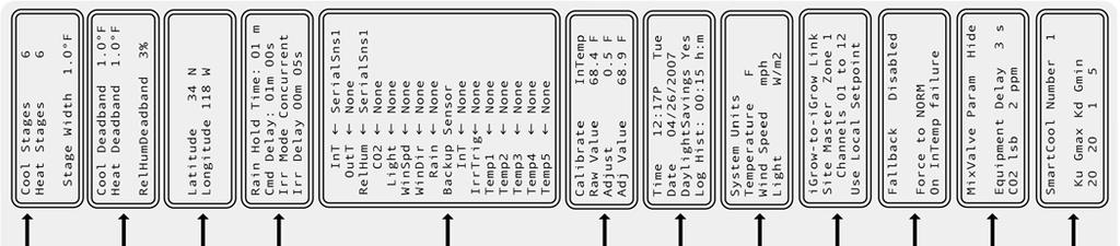
59 Programming Screens Begin Programming From any Status Screen, press the ENTER/MENU key to enter programming mode. Press NEXT and PREV to scroll up and down in this screen. To make changes to any of the items in the screen below, press ENTER. System Setup Setpoint/TimePeriod Program Equipment Dehumidify/Humidify Stage Overrides Equipment Overrides Smart Cool Settings Setpoint Alarms Auxiliary Controls Clear History System Setup (installation settings) If you re setting up your igrow1400 for the first time, then the first task is to program all applicable items found under System Setup. If the ENTER/MENU key is pressed while the System Setup field is highlighted, then the igrow 1400 will display the Menu selection for the System Setup section of the igrow System Setup Setpoint/TimePeriod Program Equipment Dehumidify/Humidify Stage Overrides Equipment Overrides Smart Cool Settings Setpoint Alarms Auxiliary Controls Clear History igrow1400 Installation Guide Page55 Link4 (866)
60 Cool/Heat Stages Setup Deadbands Setup Location Outputs Control Setup Inputs Calibrate Inputs Time/Date & History System Units Communications Fallback Settings Advanced Settings Smart Cool Factors Cool/Heating Stages Cool Stages 6 Heat Stages 6 Stage Width 1.0ºF On this screen you will select the maximum number of cooling and heating stages that you intend to use. The up and down arrow keys are used to increase or decrease the amount of stages for cooling and heating. If, for example, you select 2 heating stages, then in the remainder of the programming only 2 heating stages will be displayed The third selection is the Stage Width. This is the number of degrees between each of your stages, sometimes referred to as Stage Separation. Typically, users select either 1 or 2 degrees. Setup Deadbands Cool Deadband 1.0ºF Heat Deadband 1.0ºF RelHumDeadband 3% Deadband this is sometimes called hysteresis band. For cooling, it is the number of degrees the temperature needs to drop from the lower boundary of its current stage before it switches to the lower stage. Without Deadbands, equipment tends to cycle frequently & constantly change stages when the temperature approaches the set points. When a large value is used, setpoints may not be maintained. Typical values might be 1 to 2 degrees F. For heating it is the number of degrees the temperature needs to rise above the temperature boundary before it switches to a lower heating stage. RelHum Deadband igrow1400 Installation Guide Page56 Link4 (866)
61 This is the RH% the humidity must drop below the dehumidification threshold before exiting the dehumidification state. It also is the RH% the humidity must rise above the humidification threshold before exiting the humidification threshold. Bheat Deadband This is the number of degrees that the bottom heat temperature must rise above the bottom heat temperature setpoint or threshold before the heat valve switches off. Typical values might be 1 degree F or less. Setup Location Latitude 34 N Longitude 118 W The igrow 1400 has an internal astronomical clock. By knowing the actual coordinates, sunrise and sunset times can be precisely calculated. Go to to find coordinates for your precise location. If a negative longitude is given you are west, and if a negative latitude is given you are south. Outputs Control Rain Hold Time: 01 m Cmd Delay: 01 m 00 s Irr Mode Concurrent Irr Delay 00 m 05 s Relay Order 12->1 Rain Hold Time Rain Hold Time is a parameter that lets you choose how long you want the rain override condition to persist after the rain status goes from Yes to No. This is to keep intermittent rain from causing the vents to keep opening and closing. Cmd Delay Cmd Delay is the time between commands to change the equipments states. It is the shortest time permitted for switching equipments. Typical update times are from 1 to 2 minutes. This parameter is used to minimize the cycling of the equipment. Irr Mode Irr Mode is either Concurrent or Sequential. You can choose between the two options by pressing the + or - key. These options apply if you program more than one irrigation valve to trigger based on accumulated light or a dry contact switch closure, or if you select the cycling (misting) option. If you select Concurrent, then the valves will turn on immediately when requested regardless of how many are already on. If you select Sequential, then igrow1400 Installation Guide Page57 Link4 (866)
62 the first one will turn on but if other valves are to come on, they will wait in queue and each one will come on in succession. (Also see Jumper section to make sure your settings are correct). Irr Delay Irr Delay forces a user definable delay between the valves. In other words, when the current On valve goes Off, the next valve in the queue will wait the selected min and sec before it turns On. Relay Order The Relay Order parameter allows you to change the order that relays turn on if more than one output relay is programmed to turn on at the same time. By default, Relay Order is set to 12->1 which means that if two or more output relays are programmed to turn on at the same time, the output relay with the highest channel number will turn on first. This ordering can be reversed by changing this setting to 1->12. igrow1400 Installation Guide Page58 Link4 (866)
63 Setup Inputs (sensor mapping) InT SerialSns1 OutT SerialSns2 RelHum SerialSns1 CO2 AnalogIn6 Light Solar WinSpd FDIn1 WinDir AnalogIn7 Rain FDIn2 Backup Sensor InT SerialSns2 IrrTrig DigitalIn1 Temp1 AnalogIn1 Temp2 AnalogIn2 Temp3 AnalogIn3 Temp4 AnalogIn4 Temp5 AnalogIn5 Setup Inputs is where you tell your igrow1400 what sensors you have (this is also called sensor mapping). The screen above show the typical sensor mapping for each sensor. If you don t have a particular sensor then leave the setting as None. Note: For Zone Master and Slave units, you should set all weather station sensors (OutT, Light, WindSpd, WindDir, and Rain to Remote. Setting the weather station sensors to Remote means the Slave unit or Zone Master will get their weather station data remotely from the Site Master. PREV and NEXT keys move the cursor from one input selection to the next. Using the + and - keys you can select which one of the input channels to assign to your sensors. Note that the allowable choices vary from one type of sensor to another. If any given sensor is not present, None should be selected. The Software choice is useful for testing and debugging if you just want to force the reading to a particular value. The software value can be modified through the Calibration Inputs screen below. The Backup Sensor is an optional way to tell the igrow 1400 which sensor it should default to in the case of a failure on the InTemp temperature sensor. Note: For the Backup Sensor to be used, to must be Enabled. See also Fallback Settings below to Enable the Backup Sensor. igrow1400 Installation Guide Page59 Link4 (866)
64 Calibrate Inputs Calibrate Raw Value Adjust Adj Value InTemp 73.6ºF 0.5ºF 74.1ºF Calibrate To calibrate an input you must first select the sensor you want to calibrate. Press the + or - keys to cycle through the various sensors. Once you have selected your sensor, press enter and it will take you to the adjustment line. Raw Value Raw Value is the direct reading from the sensor. Using the + or - keys will add a positive or negative adjustment to the raw reading giving you an adjusted value. Adj Value Adj Value is what will be reflected on the front status screen. Time/Date & History Time 12:17P Date 04/26/2005 Tue DaylightSavings Yes Log Hist: 00:01 h:m Time Time adjusts the current time by highlighting the field and pressing either the + or - keys. This will allow you to scroll through the entire 24 hours. Date Do the same for the date. Press Enter to go from field to field and adjust the correct date. Daylight Savings If you want the program to automatically adjust itself for Daylight savings time, select YES. If not, select NO. Log History This option lets you choose how often the controller will log sensor and equipment history information. In this case it saves log history every minute, but can be changed to different lengths of time. If you put 00:00, then it will save information every second. Note: In the United States and Canada Daylight Saving Time begins on the second Sunday in March and reverts back to standard time on the first Sunday in November. igrow1400 Installation Guide Page60 Link4 (866)
65 System Units System Units Temperature ºF Wind Speed mph Light W/m 2 Temperature Choose either degrees Fahrenheit (ºF) or degrees Centigrade (ºC). Wind Speed Choose either miles per hour (mph) or kilometers per hour (km/h). Light Choose either Watts/meter 2 or klux. Communications (Network Programming) Once multiple igrow controllers are wired together (as shown in Figure 4.21), you will need to set up each igrow1400 s program settings for proper communications. Note that the most important igrow1400 in the network is the one you choose to be the Site Master. The Site Master controls all network communications and is the only unit that a Weather Station and PC can be connected to. Site Master To setup your Site Master press Enter/Menu System Setup Communications. Under the Communications screen you ll find several editable fields. By default the text Disabled will be highlighted. Use the + and - buttons to change this setting to Site Master. Now press the BACK button three times (or until you see the Main Status screen) to save your changes. That is all that s necessary to setup the Site Master. Your Site Master is now ready to communicate with you network and PC. igrow-to-igrow Link Site Master Zone 1 Channels 01 to 12 Use Local Setpoint Zone Master To add a Zone, simply set a unit to Zone Master, You can set the Zone number, and choose to use it s own Local setpoints or the Site Masters Remote setpoints. Now press the BACK button three times (or until you see the Main Status screen) to save your changes. Local setpoints are the setpoints on the Zone Master itself Remote setpoints are the setpoints of the Site Master Unit igrow-to-igrow Link Zone Master Zone 2 Channels 01 to 12 Use Local Setpoint igrow1400 Installation Guide Page61 Link4 (866)
66 Note: Be sure that ZoneMaster Units are set up in sequential order. For Example, if you have three Zone Masters, set their zone numberto be in order i.e. 2,3,4. DO NOT jump over one such as 2,4,5. The icontrol software will not function properly. Slave Unit For Slave Units (also called Expansion Units), set to Slave Unit. Then set which zone the unit will be an expansion unit to, i.e. Site Master Zone 1, or some other Zone Master. Since each zone can have up to 3 Expansion Units you must also decide which expansion unit it is. Expansion Unit Outputs Expansion Unit Outputs Expansion Unit Outputs Note: Be sure that Expansion Units are set up in sequential order. For Example, if you have only two expansion units be sure to set one as an the other to DO NOT jump over one such as and The icontrol software will not function properly. igrow-to-igrow Link Slave Unit Zone 1 Channels 13 to 24 Use Remote Setpoint Similar to a Zone Master, you can choose to use Local or Remote Setpoints. But in this case, if you choose Remote setpoints, the Expansion unit will use the Zone Master s setpoints NOT the Site Master s setpoints. Now press the BACK button three times (or until you see the Main Status screen) to save your changes. Note: Once you setup the Site Master, Zone Master(s) and Expansion Unit(s), you should label the front panel on each unit for easier reference in the future. Fallback Settings Fallback Disabled Force to NORM On InTemp failure Fallback This feature is used if there is an InTemp sensor failure and you want the controller to fallback into utilizing the Backup Sensor (OutTemp, or other temp sensor you have defined in the Setup Inputs section). By choosing the fallback option to Enabled mode, the controller will automatically detect an InTemp sensor failure and fall back to the Backup Sensor. If Fallback is Disabled, then there is no action to utilize a backup sensor and the igrow 1400 will engage the Force to condition. Note: In the event of an InTemp sensor failure, both High & Low Alarms will immediately be triggered. igrow1400 Installation Guide Page62 Link4 (866)
67 Force to In case of a Fallback failure scenario, or if Fallback is Disabled, the third level of safety is to force the igrow 1400 into any stage automatically. In the example screen above, the igrow 1400 would engage whatever equipment you have assigned to be ON under NORM conditions. Advanced Settings MixValve Param Hide Equipment Delay 3 s CO2 lsb 2 ppm Curtain Energy Mode Light Hyst 50% Temp Hyst + 5ºF Advanced If you wish to use PID Mix Valve operation then the MixValve Param option must be set to from Hide to Show. This will activate two additional menu screens located under the MixV equipment type menu. Use the + and - keys to change setting from Hide to Show. Equipment Delay Time the igrow1400 will wait to switch from one equipment to the next. CO2 lsb Tuning range for a CO2 sensor (modifies the ranging of a CO2 sensor) 2 means the CO2 range will be ppm, a value of 3 would set the range to be ppm. Light Hyst Light Hysteresis only applies to curtains in Energy Mode. Once a curtain closes, for it to reopen due to light, the new light reading must be higher than the close value by: Close Value times Hyst value plus the Close Value. For example, let s say the Hyst Vlaue is 50%. If the curtain closes at 100W/m², then to reopen it the light level must reach 150 W/m² (or 100x50% + 100). Temp Hyst Temp Hysteresis is similar to Light Hysteresis, and only applies to curtains in Energy Mode. Once a curtain closes, for it to reopen due to temperature, the new temperature reading must be higher than the close value by: Close Value plus the Temp Hysteresis value. For example, let s say the Hyst Vlaue is +5ºF. If the curtain closes at 70ºF, then to reopen it the temperature level must reach 75ºF (or 70+ 5). Note: Regardless of what causes a curtain to close, during energy mode either Light Hyst or Temp Hyst can reopen it. igrow1400 Installation Guide Page63 Link4 (866)
68 SmartCool Factors SmartCool Number 1 Ku Gmax Kd Gmin Smart Cool uses the outside temperature and light data to assist in making intelligent cool staging decisions for the most efficient control of your greenhouse. In the first level of screens, there is a similarly named panel called Smart Cool Settings. SmartCool Factors and Smart Cool Settings panels are related to each other. In the Smart Cool Settings panel there are 10 possible settings you can choose from, each one determining how aggressively your igrow will respond to changing weather conditions. SmartCool Factors are the detailed settings for each of the 1-10 Smart Cool Settings. Note: Smart Cool Factors are settings related to how quickly your greenhouse heats up and cools down. The igrow1400 allows you to adjust the Smart Cool Factors, but it is NOT RECOMMENDED TO CHANGE THE DEFAULT SETTINGS. To use Smart Cool, you should only adjust the 1-10 values found in the Smart Cool Settings panel. For further information on Smart Cool, please contact Link4. Setpoint/Time Period Programming System Setup Setpoint/TimePeriod Program Equipment Dehumidify/Humidify Stage Overrides Equipment Overrides Setpoint Alarms Setpoint 1 Enabled Start 6:00A Ramp30m Temp 68.0 to 72.0ºF RelHum 10 to 80 % Start Times You have up to 4 setpoint start times available to use within a 24 hour time period. You can cycle through each of the four start times with the + or - keys. Pressing Enter takes you to the Enabled or Disabled option. Setpoint 1 is always enabled. Setpoint s 2-4 are disabled. You may enable them by use of the + key. igrow1400 Installation Guide Page64 Link4 (866)
69 Note: If you only have day and night setpoints, you will only use Setpoint 1 and Setpoint 2, the other two will remain disabled The Start time is when the heat and cool temperature setpoints temperatures are engaged. The start time is either a fixed time or it can vary daily based on the increase or decrease in day length. This day length is an Astronomic Adjustment based on the latitude and longitude entries that you made as shown in the Setup Location portion of this manual. By pressing the + key at the Start Time entry, you will get the following: Press + once = SRise Press + twice = SSet You would use the Srise option for the setpoint that you program at the beginning of the day. Similarly, you would use the Sset option for the end of the day setpoint. The adjustment will be made each midnight and so everyday you will see a change in the Start Time. Ramp Time The ramp time enables a smooth transition of the target temperatures between the time periods. If the ramp time is set to 0 there will be an immediate step transition in the set points from the previous from the current setpoint to the following time period. If the ramp time is not zero, the ramping begins at the end of the time period (see Fig 2.1 for reference). Heat and Cool Setpoints The third line is where you enter the heat and the cool setpoints, that is, the low temperature and the high temperature targets. Humidity Setpoints The humidity range is shown on the fourth line. If the humidity is below the lower value, you enter the humidification stage. If humidity is above the higher number you go into the dehumidification stage. igrow1400 Installation Guide Page65 Link4 (866)
70 Programming Equipment System Setup Setpoint/TimePeriod Program Equipment Dehumidify/Humidify Stage Overrides Equipment Overrides Alarm Limits Clear History 01 Name1 None This channel has no selected equipment. To setup or change equipments press the ENTER/MENU button, use the + and buttons to find Program Equipment selection, then press ENTER/MENU again. You will then see the right screen above. To select the output channel that you want to edit press ENTER/MENU one more time and the CH01 01 in the upper left corner will highlight. Use the + and buttons to select the channel you want to edit. Once the channel is selected, the next two steps are to name the channel (usually named by the equipment type it s controlling), and to set what kind of equipment it is. For un-programmed equipment, there are two editable choices: the name field and the equipment type field. The names are restricted to 5 alphanumeric characters. The equipment type field is restricted to the following equipment types: On/Off On/Off may be programmed on any channel Irrig Irrig may be programmed on any channel CO2 CO2 may be programmed on any channel Light Light may be programmed on any channel Pump - Pump may be programmed on any channel MZone MZone (or Microzone) is an On/Off type device with its own setpoints and temp sensor (temp probe only). It is an independent thermostat output with Day/Night settings. It can be programmed on any Channel. Vent Vent may only be programmed on any two consecutive channels, the first channel being an odd number and the second it s neighboring even number (for example: channels 1&2 or 3&4 are acceptable pairs, but 2&3, or 8&9 are not) Curtain Curtain may only be programmed on any two consecutive channels, the first channel being an odd number and the second it s neighboring even number (for example: channels 1&2 or 3&4 are MixV acceptable pairs, but 2&3, or 8&9 are not) MixV may only be programmed on any two consecutive channels, the first channel being an odd number and the second it s neighboring even number (for example: channels 1&2 or 3&4 are acceptable pairs, but 2&3, or 8&9 are not) PZone PZone a special purpose Mixvalve, and is a proportional controlled MicroZone. It may only be programmed on any two consecutive channels, the first channel being an odd number and the second it s neighboring even number (for example: channels 1&2 or 3&4 are acceptable pairs, but 2&3, or 8&9 are not) It is an independent thermostat output that can control modulating heat valves. igrow1400 Installation Guide Page66 Link4 (866)
71 ON/OFF Equipment 02 ExF 1 OnOff Heat Cool N The igrow 1400 supports On/Off devices with up to 6 heating and 6 cooling stages. 1 to turn equipment ON and 0 to turn it OFF. Use the + or keys to toggle the On/Off condition for a particular stage. In the above example, we have the exhaust fan coming on beginning with the second stage of cooling and then continuing on in the remaining six cooling stages. Note: If in the Cooling/Heating Stage setup you selected fewer than 6 stages, then only the number of stages that you selected will appear for the On/Off devices and Vents (Refer to Cool/Heating Stages Setup to set how many stages are desirable). Irrigation Programming 01 Valve1 Irr Mode: Scheduled Hr mm ss OnTime: 00:00:00 Each channel programmed for Irr (irrigation) can be programmed independently. The first selection is the Mode. Pressing the + or keys cycles you through the mode choices. There are four choices defined as follows: Scheduled This mode is like a time clock where you set the start time, run time and days of the week. Accumulated Light In this mode the irrigation cycle is triggered when the accumulated light or light sum reaches a threshold or when the off time limit is reached. Cycle With this option, the irrigation valve is cycled continuously during the time window with an On time and an Off time that you get to select. Cycle Temp Similar to Cycle, except that the On time can be adjusted based on interior temperature. Trigger This option lets you trigger the irrigation based on an external input. This input could be a wall switch, a moisture sensor, a weighing scale or any on/off input. igrow1400 Installation Guide Page67 Link4 (866)
72 Scheduled Irrigation 01 Irr01 Irr Mode: Scheduled hr mm ss 01 Irr01 Irr 7:00A 8:00A 12:30P 4:00P Off Off 01 Irr01 Irr SMTWTFS SMTWTFS Scheduled mode allows the igrow 1400 to turn the Irrigation channel on for a duration equal to OnTime at up to six start times per day. Use Off to indicate unused time slot. The third screen allows for enabling or disabling scheduled irrigation for an entire day. A 1 indicates that irrigation is enabled for that particular day, and a 0 means irrigation is disabled for that day. Two weeks are given, so that the igrow 1400 can be configured to irrigate every other day. In the above example, the equipment, named Irr01, is scheduled to turn on for 2 minutes, every other day of the week, at 7a.m., 8a.m., 12:30p.m., and 4p.m. Note: These times are not astronomically adjusted. Accumulated Light Irrigation 02 Irr02 Irr Mode: Accum Light hr mm ss Accumulated light mode allows the igrow 1400 to turn the Irrigation channel on for a duration equal to the OnTime. 02 Irr02 Irr Start _SRise 07:00A End at 07:30P Accum Light The irrigation valve will only turn on between the Start time and End time and will only do so when the appropriate amount of light has been accumulated. Both of the start and end times can be astronomically adjusted to vary igrow1400 Installation Guide Page68 Link4 (866)

73 with respect to either sunrise or sunset. Please note that if the accumulation does not reach the threshold at the end of the time window the accumulation will still continue, however, if the threshold is reached outside the time window, irrigation will not take place until the beginning of the next active time window. 02 Irr02 Irr 6000 W/m2h at 55 F 3500 W/m2h at 85 F Max Off 8:00 hh:mm In the third screen you will need to set the accumulated light threshold. You have the option of setting it as a function of the air temperature. For example, you might have a threshold of 6000 w/m2-hr at a temperature of 70 ºF and a threshold of 5550 w/m2-hr at an air temperature of 80 ºF. The threshold will then be a straight line interpolation between the two temperature thresholds. Note: If you don t want it set as a function of temperature, then simply make the two accumulated light entries the same. S1 = 6.0 kw/m2 at 85 F 02 Irr02 Irr 6000 W/m2h at 55 F 3500 W/m2h at 85 F Max Off 8:00 hh:mm S2 = 3.5 kw/m2 at 55 F The crosshairs represent the irrigation trigger point. This location will change as the actual temperature changes The last entry is the Max off time. This is similar to a safety net. In the event that the accumulated light is below the threshold when the maximum off time is reached, irrigation will take place anyway and the accumulator will be reset. Note: In order to use this feature properly, there has to be a light sensor attached to the igrow 1400 and it must be mapped correctly in the Setup Input screen. Cycling Irrigation 03 Irr03 Irr Mode: Cycle hr mm ss igrow1400 Installation Guide Page69 Link4 (866)
iponic 600 I N T E L L I G E N T E N V I R O N M E N T A L C O N T R O L L E R
 iponic 600 I N T E L L I G E N T E N V I R O N M E N T A L C O N T R O L L E R Installation and User s Guide November 2011 Preliminary Edition Copyright 2011 Corporation Table of Contents Introduction...
SUTTON 52 CEILING FAN
 SUTTON 52 CEILING FAN MODELS #50188, 50189, 50190 Español p. 19 Questions, problems, missing parts? Before returning to your retailer, call our customer service department at 1-877-361-3883, Monday - Thursday,
TOUCHDOWN 48 CEILING FAN
 TOUCHDOWN 48 CEILING FAN MODEL #50205 Español p. 20 Questions, problems, missing parts? Before returning to your retailer, call our customer service department at 1-877-361-3883, Monday - Thursday, 8 am
MICRO GROW GREENHOUSE SYSTEMS, INC ZEVO DR., SUITE B-1, TEMECULA, CA PHONE (951) FAX (951) Growmate Growmate Plus
 FAX (951) Growmate Growmate Plus") MICRO GROW GREENHOUSE SYSTEMS, INC 42065 ZEVO DR., SUITE B-1, TEMECULA, CA 92590 PHONE (951)-296-3340 FAX (951)-296-3350 Growmate Growmate Plus INSTALLATION PROCEDURES GROWMASTER AND GROWMATE SERIES OF
MICRO GROW GREENHOUSE SYSTEMS, INC 42065 ZEVO DR., SUITE B-1, TEMECULA, CA 92590 PHONE (951)-296-3340 FAX (951)-296-3350 Growmate Growmate Plus INSTALLATION PROCEDURES GROWMASTER AND GROWMATE SERIES OF
USER MANUAL MODEL READ ALL INSTRUCTIONS BEFORE PROCEEDING. 5-2 Day Programmable Multi-Stage 2 Heat/1 Cool Heat Pump Digital Thermostat
 WARNING! Important Safety Information Builder MODEL 2200 Series 5-2 Day Programmable Multi-Stage 2 Heat/1 Cool Heat Pump Digital Thermostat USER MANUAL Compatible with low voltage multi stage heat/cool
DUVAL 52 CEILING FAN MODELS #50201, Español p. 19 LISTED FOR DAMP LOCATION
 DUVAL 52 CEILING FAN MODELS #50201, 50206 Español p. 19 LISTED FOR DAMP LOCATION Questions, problems, missing parts? Before returning to your retailer, call our customer service department at 1-877-361-3883,
MICRO GROW GREENHOUSE SYSTEMS, INC
 MICRO GROW GREENHOUSE SYSTEMS, INC 26111 YNEZ RD., SUITE C-4, TEMECULA, CA 92591 PHONE (951)-296-3340 FAX (951)-296-3350 Revision 1.3, 8/30/04 Ventmate Plus INSTALLATION PROCEDURES GROWMASTER, GROWMATE
USER MANUAL 2000NC MODEL READ ALL INSTRUCTIONS BEFORE PROCEEDING. Builder Series 5-2 Day Programmable Single Stage Heat/Cool Digital Thermostat
 MODEL 2000NC USER MANUAL Builder Series 5-2 Day Programmable Single Stage /Cool Digital Thermostat Compatible with low voltage single stage gas, oil or electric heating or cooling systems, including single
52 SAN LUCAS CEILING FAN
 52 SAN LUCAS CEILING FAN Owner s Manual Models #20551 If a problem cannot be remedied or you are experiencing difficulty in installation, please contact the Service Department: 1-877-459-3267, 9 a.m.-
Operating Instructions. Temperature and Humidity EC Control. Model 35YV93
 Operating Instructions EN Temperature and Humidity EC Control Model 35YV93 479702 PLEASE READ AND SAVE THESE INSTRUCTIONS. READ CAREFULLY BEFORE ATTEMPTING TO ASSEMBLE, INSTALL, OPERATE OR MAINTAIN THE
ELSTON 52 CEILING FAN
 ELSTON 52 CEILING FAN MODEL #10290 Español p. 21 Questions, problems, missing parts? Before returning to your retailer, call our customer service department at 1-877-361-3883, Monday - Thursday, 8 am -
SPRINGHILL 44 CEILING FAN
 SPRINGHILL 44 CEILING FAN MODELS #50184, 50185 Español p. 20 Questions, problems, missing parts? Before returning to your retailer, call our customer service department at 1-877-361-3883, Monday - Thursday,
SC Installation, Operation & Application Guide
 SC 5211 2-Stage Heat Pump Auto Changeover Hardwire Programmable Electronic Thermostat 7-Day, 5-2-Day or 5-1-1-Day Programmable Configurable 2-Stage Heat Pump Systems Large Display With Backlight Selectable
installation and operation manual for Hunter Ceiling Fans
 For Your Records and Warranty Assistance Model Name: Catalog/Model No.: Serial No.: Date Purchased: Where Purchased: For reference also attach your receipt or a copy of your receipt to the manual. installation
48 TAYLOR CEILING FAN
 48 TAYLOR CEILING FAN Owner s Manual Models #20554 If a problem cannot be remedied or you are experiencing difficulty in installation, please contact the Service Department: 1-877-459-3267, 9 a.m.- 5 p.m.
ST. KITTS CEILING FAN
 ITEM #0845047 ST. KITTS CEILING FAN MODEL #40829 Questions, problems or missing parts? Before returning this item to your retailer, call our customer service department at 1-800-643-0067, Monday - Thursday,
Duct and Rough Service Carbon Monoxide Sensor
 Product Identification and Overview Duct and Rough Service Carbon Monoxide Sensor BAPI s Carbon Monoxide Sensor offers enhanced electrochemical sensing with outstanding accuracy at low concentrations.
OWNERS MANUAL YEAR LIMITED WARRANTY READ ALL INSTRUCTIONS BEFORE PROCEEDING. Store this booklet for future reference
 3000 Premier Series Non-Programmable Single Stage /Cool Digital Thermostat OWNERS MANUAL Compatible with low voltage single stage gas, oil or electric heating or cooling systems, including single stage
USER MANUAL WARNING! CONTENTS MODEL 1 SPECIFICATIONS READ ALL INSTRUCTIONS BEFORE PROCEEDING 2 INSTALLATION. Premier Series
 Premier Series MODEL 5000 USER MANUAL 5-2 Day Programmable Single Stage Heat/Cool Digital Thermostat Compatible with low voltage single stage gas, oil or electric heating or cooling systems, including
Model NT20e Installation Guide
 Model NT20e Installation Guide Rev 1.4 Page 2 of 14 1. Preparing for Installation CAUTION Do not remove the NT20e from the Electro-static bag until instructed from this installation guide. The NT20e is
F PC and AO OUTPUT BOARDS INSTRUCTION MANUAL. Blue-White. Industries, Ltd.
 F-2000 PC and AO OUTPUT BOARDS INSTRUCTION MANUAL Blue-White R Industries, Ltd. 500 Business Drive Huntington Beach, CA 92649 USA Phone: 714-89-8529 FAX: 714-894-9492 E mail: sales@blue-white.com or techsupport@blue-white.com
OWNERS MANUAL YEAR LIMITED WARRANTY READ ALL INSTRUCTIONS BEFORE PROCEEDING. Store this booklet for future reference
 3100 Premier Series Non-Programmable 2 Heat / 2Cool & Heat / Cool Digital Thermostat OWNERS MANUAL Compatible with low voltage multi-stage heat / cool systems with up to two stages of heating and two stages
Protocol Station Remote Alarm
 ADI 5135-C Certified ISO 9001 Protocol Station Remote Alarm 529 5135-01-120 529 5135-01-220 INSTALLATION AND OPERATING INSTRUCTIONS Carefully Read These Instructions Before Operating Controls Corporation
HI Industrial Utility Heater HI Soleus Air International
 HI1-50-03 Industrial Utility Heater HI1-50-03 2010 Soleus Air International Thank you for choosing a Soleus Air Utility Heater. This owner s manual will provide you with valuable information necessary
SC Installation, Operation & Application Guide
 SC 3006 Auto Changeover 7-Day Programmable Hardwired Programmable Electronic Thermostat 7-Day Programmable Single Stage Heat Pump/Non-Heat Pump Systems Backlit Display Single Stage Heat/Cool Systems Field
TMC. Installation and Operation Manual TMC. Temperature and Pressure Monitoring for Heating and Cooling Applications. Temperature Monitoring Control
 Installation and Operation Manual Temperature and Pressure Monitoring for Heating and Cooling Applications Temperature Monitoring Control VALVE OPEN ALARM System= 128 o F Alarm At= 130 o F RESET /BACK
INSTALLATION & OPERATION MANUAL
 INSTALLATION & OPERATION MANUAL Model TME- * * Balance of model number is determined by customer specifi ed limits and Setbacks. AUTOMATIC SETBACK THERMOSTAT LIGHT SENSING OR CONTACT CLOSURE FOR LOW VOLTAGE
Proliphix Thermostat Installation Guide. Release 2.0
 Proliphix Thermostat Installation Guide Release 2.0 July 2006 Beta Draft Confidential Technical Support When contacting Proliphix for technical assistance, please have the following information available:
52 BERKSHIRE CEILING FAN
 52 BERKSHIRE CEILING FAN Owner s Manual Models #20223, 20224 If a problem cannot be remedied or you are experiencing difficulty in installation, please contact the Service Department: 1-877-459-3267, 9
LIMITED LIFETIME WARRANTY
 LIMITED LIFETIME WARRANTY To obtain Service, please contact or call Turn of the Century Service Department: 1-800-887-6326, 9 a.m.- 5 p.m. central time. Model No.: # 355-6782 The limited lifetime warranty
Model 6021 Electrically Heated Rain and Snow Gauge
 Model 6021 Electrically Heated Rain and Snow Gauge User s Manual 1165 National Drive Sacramento, California 95834 USA www.allweatherinc.com Table of Contents General Information... 1 Introduction... 1
SC-6 Six Supervised Control Module
 INSTALLATION AND MAINTENANCE INSTRUCTIONS SC-6 Six Supervised Control Module SPECIFICATIONS Normal Operating Voltage: Stand-By Current: Alarm Current: Temperature Range: Humidity: Dimensions: Accessories:
Combustible Gas Sample-Draw Detector Operator s Manual
 35-3001-01 Combustible Gas Sample-Draw Detector Operator s Manual Part Number: 71-0282RK Revision: A Released: 8/3/17 www.rkiinstruments.com WARNING Read and understand this instruction manual before operating
Models LBW-420-LEL (24 VDC powered) Ammonia Leak Detector
 Ammonia Leak Detector") Models LBW-420-LEL (24 VDC powered) Ammonia Leak Detector CAUTION & SYMBOL DEFINITIONS: CAUTION: Gives detailed description of different situations to avoid or not avoid for the proper operation of the
Models LBW-420-LEL (24 VDC powered) Ammonia Leak Detector CAUTION & SYMBOL DEFINITIONS: CAUTION: Gives detailed description of different situations to avoid or not avoid for the proper operation of the
TURBO Fiberglass Cone Fan and Grill Fan 48'' Belt Drive. Installation & Operator s Instruction Manual
 TURBO Fiberglass Cone Fan and Grill Fan 48'' Belt Drive Installation & Operator s Instruction Manual July 1998 MV1383B Chore-Time TURBO TM Fan Extended Warranty Chore-Time Equipment warrants new TURBO
F AN-ASPIRATED RADIATION SHIELD
 F AN-ASPIRATED RADIATION SHIELD I NSTALLATION MANUAL (For all models with Mfg. Code beginning with B or higher) The Fan-Aspirated Radiation Shield uses fan aspiration and passive shielding to minimize
SAFETY INFORMATION AND WARNINGS
 This manual refers to the Model SST-3 control panel manufactured since October 31, 2013, which uses a universal (100 277 VAC; 50/60 Hz) power supply. Older units use a voltage-specific power supply and
TILGHMAN CEILING FAN. LISTED For Damp Location E ITEM # MODEL #WCK52LMW5N WCK52NWZ5N. Español p. 20 ATTACH YOUR RECEIPT HERE
 ITEM #0294980 0294981 TILGHMAN CEILING FAN Harbor Breeze is a registered trademark of LF, LLC. All Rights Reserved. MODEL #WCK52LMW5N WCK52NWZ5N Español p. 20 ATTACH YOUR RECEIPT HERE Serial Number Purchase
Environmental Monitoring SmartSlot Card
 Environmental Monitoring SmartSlot Card AP9612TH Installation and Quick Start Manual Contents Introduction............................. 1 Overview 1 Product inventory 1 Safety notice 2 Your inspection
Environmental Monitoring Card
 Environmental Monitoring ard AP9612TH Installation and Quick-Start Manual ontents Introduction............................. 1 Overview............................. 1 Product inventory......................
HD-26, HD-36, HD-48 Heated Displays
 HD-26, HD-36, HD-48 Heated Displays This manual contains important information regarding your Admiral Craft unit. Please read this manual thoroughly prior to equipment set-up, operation and maintenance.
Owner s Guide and Installation Manual
 For Your Records and Warranty Assistance For reference, also attach your receipt or a copy of your receipt to the manual. Model Name Type 2 Models Owner s Guide and Installation Manual Model No. Catalog
Here is what comes in your box:
 Here is what comes in your box: We recommend that you pull everything out of the box and lay it out. We have grouped the drawn components below with the hardware you ll need for those parts. The screws
USER MANUAL WARNING! CONTENTS MODEL SPECIFICATIONS READ ALL INSTRUCTIONS BEFORE PROCEEDING
 MODEL Premier Series 3000 USER MANUAL Non-Programmable Single Stage Heat/Cool Digital Thermostat Compatible with low voltage single stage gas, oil or electric heating or cooling systems, including single
IMPORTANT WARNINGS IMPORTANT SAFETY INSTRUCTIONS
 IMPORTANT WARNINGS IMPORTANT SAFETY INSTRUCTIONS Suncourt recommends professional installation of the Airiva (or by an accomplished DIY person) Please read and save these entire instructions before starting
Single Station Remote Alarm
 ADI 5106C Certified ISO 9001 Single Station Remote Alarm 529 5106-01-120 529 5106-01-220 INSTALLATION AND OPERATING INSTRUCTIONS Carefully Read These Instructions Before Operating Controls Corporation
52 BAYTOWNE CEILING FAN
 52 BAYTOWNE CEILING FAN Owner s Manual Models #20501 If a problem cannot be remedied or you are experiencing difficulty in installation, please contact the Service Department: 1-877-459-3267, 9 a.m.- 5
Camarillo 52 Ceiling Fan
 Owner s Manual Camarillo 52 Ceiling Fan Part # 269263, 269259, 269287 Model # 32091, 32092, 32087 Exclusively Distributed by: HD Supply Facilities Maintenance, Ltd. Atlanta, GA 30339 2017 Made in China
ALUMA INSTRUCTION MANUAL WARRANTY CERTIFICATE
 ALUMA BY INSTRUCTION MANUAL WARRANTY CERTIFICATE Manual design and all elements of manual design are protected by U.S. Federal and/or State Law, including Patent, Trademark and/or Copyright laws. The Minka-Aire
Installation Manual. Breeder Control Installation Manual Patented U.S. Patent No. 7,980,129 and Patents Pending
 Breeder Control Installation Manual Patented U.S. Patent No. 7,980,129 and Patents Pending 11/25/2013 Table of Contents Installation Overview... 3 Components... 3 BinTrac Breeder Control... 3 Load Cell
CMT MANUAL 6. NMC SENSORS
 CMT MANUAL 6. NMC SENSORS TABLE OF CONTENTS INDEMNITY... 5 DOCUMENT INFORMATION... 5 ACKNOWLEDGEMENTS... 5 6.1 INTRODUCTION... 6 6.2 TEMPERATURE AND HUMIDITY SENSORS... 7 6.2.1. TEMPERATURE SENSOR... 7
ITEM # BUILDER S SERIES CEILING FAN MODEL #41391
 Harbor Breeze Harb or Breeze ITEM #0915543 BUILDER S SERIES CEILING FAN MODEL #41391 Harbor Breeze is a registered trademark of LF, LLC. All Rights Reserved. Español p. 18 ATTACH YOUR RECEIPT HERE Purchase
RK-OXY Oxygen Sample-Draw Detector Operator s Manual Part Number: RK Revision: P1 Released: 7/18/02
 35-3000RK-OXY Oxygen Sample-Draw Detector Operator s Manual Part Number: 71-0071RK Revision: P1 Released: 7/18/02 RKI Instruments Inc. 1855 Whipple Road Hayward, CA 94544 PH: 800-754-5165 Fax: 510-441-5650
TACH-IT MODEL #3568 SEMI-AUTOMATIC TWIST TIE MACHINE OPERATION MANUAL AND PARTS LIST
 TACH-IT MODEL #3568 SEMI-AUTOMATIC TWIST TIE MACHINE OPERATION MANUAL AND PARTS LIST 1 TABLE OF CONTENTS: SECTION 1 CAUTION PAGE 3 SECTION 2 PARTS IDENTIFICATION PAGE 4 SECTION 3 MACHINE DIMENSIONS AND
RIO 54 CEILING FAN MODEL # Español p. 19
 RIO 54 CEILING FAN MODEL #50195 Español p. 19 Questions, problems, missing parts? Before returning to your retailer, call our customer service department at 1-877-361-3883, Monday - Thursday, 8 am - 6
Murano Shower Cabin Installation Instruction
 Murano Shower Cabin Installation Instruction IMPORTANT Please read carefully the following instructions before installing your shower cabin. If you have any questions on this shower cabin installation
Installation Guide. For Models: E-PD52ABZ5C4 E-PD52BP5C4 E-PD52WW5C4 READ THESE INSTRUCTIONS AND SAVE THEM FOR FUTURE USE
 READ THESE INSTRUCTIONS AND SAVE THEM FOR FUTURE USE Federal regulations require all ceiling fans with light kits manufactured or imported after January 1, 2009, to limit total wattage consumed by the
Mark 25 Ultrapure Water Conductivity Analyzer
 Martek Instruments, Inc. Mark 25 Ultrapure Water Conductivity Analyzer Instruction Manual WARRANTY POLICY Unless otherwise stated, MARTEK INSTRUMENTS, INC. warrants this equipment to be free from defects
Juna Ceiling Fan JU54. Installation Instructions Instrucciones de instalación Instructions d installation
 Juna Ceiling Fan JU54 Installation Instructions Instrucciones de instalación Instructions d installation Read and Save These Safety Precautions. Turn off electricity at main switch before wiring or servicing
Installer Guide. WARNING Important Safety Information. 1 Specifications
 1 Specifications cont. Premier Series Universal Auto Changeover Up to 3 Heat / 2 Cool Heat Pump or 2 Heat / 2 Cool Conventional Thermostat Installer Guide Before Installing, Programming or Operating, PLEASE
52 BARSTOW CEILING FAN
 52 BARSTOW CEILING FAN Owner s Manual Models #20519 If a problem cannot be remedied or you are experiencing difficulty with installation, please contact the Service Department: 1-877-459-3267, 9 a.m.-
Torrena 42 Ceiling Fan
 Torrena 42 Ceiling Fan Owner s Manual Part # 269268, 269269 Model # 32096, 32097 Exclusively Distributed by: HD Supply Facilities Maintenance, Ltd. Atlanta, GA 30339 2017 Made in China If you are experiencing
Carbon Dioxide Sample-Draw Detector Operator s Manual
 35-3001-05-03 Carbon Dioxide Sample-Draw Detector Operator s Manual Part Number: 71-0413 Revision: 0 Released: 8/4/17 www.rkiinstruments.com WARNING Read and understand this instruction manual before operating
THE BARCLAY HUGGER CEILING FAN INSTALLATION INSTRUCTIONS
 THE BARCLAY HUGGER CEILING FAN INSTALLATION INSTRUCTIONS Please read and save these instructions These instructions are to be used in the installation of the following QUORUM INTERNATIONAL fans... The
User s Manual and Operating Instructions
 User s Manual and Operating Instructions Model Numbers: PT-18W-DDF-A, PT-20F-DDF-A, PT-20S-DDF, PT-24O-DDF, PT-24-DDF, PT-24-DDF-F, PT-30-DDF, PT-30P-DDF-A, PT-30P-DDF-AF READ AND SAVE THESE INSTRUCTIONS
WARNING Important Safety Information
 1 Specifications 1 2 3 4 5 Builder Series Programmable Thermostats 2000 2000NC 2200 2200NC Single Stage Heat / Cool Conventional and Heat Pump Multi-Stage 2 Heat / 1 Cool Conventional and Heat Pump Before
SC Installation, Operation & Application Guide
 SC 3801 2 Heat/2 Cool 7-Day Programmable Hardwired Programmable Electronic Thermostat Programmable and Configurable Single/Dual Stage Heat Pump Systems Single/Dual Stage Heat/Cool Systems Backlit Display
52 CEILING FAN. Owner s Manual Models #50336, 50337
 52 CEILING FAN Owner s Manual Models #50336, 50337 If a problem cannot be remedied or you are experiencing difficulty in installation, please contact the Service Department: 1-877-706-3267, 9 a.m.- 5 p.m.
Beacon 800 Gas Monitor Operator s Manual
 Beacon 800 Gas Monitor Operator s Manual Part Number: 71-0037RK Revision: F Released: 4/18/17 www.rkiinstruments.com Product Warranty RKI Instruments, Inc. warrants gas alarm equipment sold by us to be
Irene READ AND SAVE THESE INSTRUCTIONS. FAN RATING AC 120V. 60Hz
 Irene 60", 52" or 42" CEILING FAN READ AND SAVE THESE INSTRUCTIONS FAN RATING AC 120V. 60Hz Please do not use any electric or battery powered tools in the assembly and installation of this or any Matthews
DESCRIPTIVE AND INSTALLATION INSTRUCTION MANUAL FOR MODEL G1000 AND H1000 SERIES ANNUNCIATORS
 DESCRIPTIVE AND INSTALLATION INSTRUCTION MANUAL FOR MODEL G1000 AND H1000 SERIES ANNUNCIATORS SEEKIRK, INC. 2420 Scioto Harper Dr. Columbus, OH 43204 Tel: (614) 278-9200 FAX: (614) 278-9257 email: seekirk@seekirk.com
Installation Instructions
 Aluminum Blinds Installation Instructions Echelon, Traditions & Integra Aluminum Blinds 2 Metro Aluminum Blinds *Click on any page to return to the Table of Contents* Echelon, Traditions & Integra Aluminum
Installation Guide. For Models: E-DCF52BNK5C3 E-DCF52FBZ5C3 E-DCF52MWW5C3 READ THESE INSTRUCTIONS AND SAVE THEM FOR FUTURE USE
 READ THESE INSTRUCTIONS AND SAVE THEM FOR FUTURE USE Federal regulations require ceiling fans with light kits manufactured or imported after January 1, 2009, to limit total wattage consumed by the light
Installation & Operation Manual Ice Cream Freezers
 Installation & Operation Manual Ice Cream Freezers Please read this manual completely before installing or operating this unit! BACF11 BACF15 Blue Air reserves the right to make product modification at
ITEM # , , PAWTUCKET CEILING FAN MODEL #40958, 40959, 40047
 ITEM #0803775, 0721899, 0807427 PAWTUCKET CEILING FAN MODEL #40958, 40959, 40047 Harbor Breeze is a registered trademark of LF, LLC. All Rights Reserved. Español p. 20 ATTACH YOUR RECEIPT HERE Serial Number
Installation and Operations Manual
 Installation and Operations Manual H-IM-LLC February 2018 Part No. 25092501 Replaces H-IM-LLC (01/2014) Lead Lag Control System Table of Contents General Safety Information 2 Inspection 2 Warranty Statement
Eliza 56 CEILING FAN READ AND SAVE THESE INSTRUCTIONS. FAN RATING AC 120V. 60Hz
 Eliza 56 CEILING FAN READ AND SAVE THESE INSTRUCTIONS FAN RATING AC 120V. 60Hz Please do not use any electric or battery powered tools in the assembly and installation of this or any Matthews Fan Company
Table of Contents. What to Expect with. Tools Needed. Mounting Options. Blades
 Table of Contents 1.888.830.1326 Ceiling Bracket 30 inches Ladder Downrod 3 Wiring 10 Operation, Maintenance & Cleaning Light Kit 11 Troubleshooting??? 17 15 1 13 5 Blades 9 Switch Housing 12 Canopy 6
52 STRATHMERE CEILING FAN
 52 STRATHMERE CEILING FAN Owner s Manual Models #20341 If a problem cannot be remedied or you are experiencing difficulty with installation, please contact the Service Department: 1-877-459-3267, 9 a.m.-
ELECTRIC FLAT PANEL FIREPLACE HEATER
 ELECTRIC FLAT PANEL FIREPLACE HEATER Model Numbers: WM50; WM-50-W; WS-G-01;WS-G-02 OWNER S MANUAL WARNING Read and understand this entire owner s manual, including all safety information, before plugging
OWNER S MANUAL
 OWNER S MANUAL www.airknightiaq.com THANK YOU for your purchase of the Air Knight IPG in-duct air purification system. This unit is designed to be installed into a central HVAC system and provide virtually
I NTEGRATED S ENSOR S UITE WITH F AN-ASPIRATED R ADIATION SHIELD ADDENDUM, REV B. For Vantage Pro and Vantage Pro Plus
 I NTEGRATED S ENSOR S UITE WITH F AN-ASPIRATED R ADIATION SHIELD ADDENDUM, REV B For Vantage Pro and Vantage Pro Plus The Vantage Pro Integrated Sensor Suite (ISS) with the Fan-Aspirated Radiation Shield
Installation Guide. For Models: E-MLV36BNK4LK1 E-MLV36ESP4LK1 E-MLV36WW4LK1 READ THESE INSTRUCTIONS AND AND SAVE THEM FOR FUTURE USE
 READ THESE INSTRUCTIONS AND AND SAVE THEM FOR FUTURE USE Federal regulations require ceiling fans with light kits manufactured or imported after January 1, 2009, to limit total wattage consumed by the
MODEL 8143 SIGNAL SELECTOR INSTALLATION AND OPERATION MANUAL
 MODEL 8143 SIGNAL SELECTOR INSTALLATION AND OPERATION MANUAL 95 Methodist Hill Drive Rochester, NY 14623 Phone: US +1.585.321.5800 Fax: US +1.585.321.5219 www.spectracomcorp.com Part Number 8143-5000-0050
ERD97P21-U Receiver. Installation/ Operation Manual C939M-D (7/00)
") ERD97P21-U Receiver Installation/ Operation Manual C939M-D (7/00) Pelco 3500 Pelco Way, Clovis CA 93612-5699 USA Pelco Online @ http://www.pelco.com In North America and Canada: Tel (800) 289-9100 or FAX
ERD97P21-U Receiver Installation/ Operation Manual C939M-D (7/00) Pelco 3500 Pelco Way, Clovis CA 93612-5699 USA Pelco Online @ http://www.pelco.com In North America and Canada: Tel (800) 289-9100 or FAX
Table of Contents What to Expect with Your Installation. Top Housing. Ceiling Plate. Tools Needed.
 Table of Contents Congratulations on purchasing your new Hunter ceiling fan! It will provide comfort and performance in your home or office for many years. This installation and operation manual contains
MAYFIELD CEILING FAN LISTED E ITEM # MODEL #BTH44ABZC5C BTH44BNK5C Español p. 20 ATTACH YOUR RECEIPT HERE.
 Harbor Breeze is a registered trademark of LF, LLC. All Rights Reserved. ITEM #0331094 0331096 MAYFIELD CEILING FAN MODEL #BTH44ABZC5C BTH44BNK5C Español p. 20 ATTACH YOUR RECEIPT HERE Serial Number Purchase
WHEATGRASS JUICER C O M M E R C I A L. INSTRUCTION MANUAL Model No
 COMMERCIAL PRODUCTS ATTENTION If any components of this unit are broken, do not operate properly, or for product returns, please contact Pragotrade at 1-800-814-4895 Outside the U.S. call 440-638-3131.
Irene READ AND SAVE THESE INSTRUCTIONS
 Irene 60", 52" or 42" CEILING FAN READ AND SAVE THESE INSTRUCTIONS FAN RATING AC 120V. 60Hz For Damp Location QUICK ASSEMBLY NOTES: * Do not wire in fan while house wires are Live. Turn power off at breaker
WAILEA OWNER S MANUAL
 WAILEA OWNER S MANUAL The blades in each pack are matched for equal weight to assure smooth fan operation. If more than one fan is being installed, be careful not to mix blades from different cartons.
Auto Opening with Pressure Readout 15 x15 & 16 x20 Heat Transfer Machines
 S-450P & S-650P Auto Opening with Pressure Readout 15 x15 & 16 x20 Heat Transfer Machines OWNER S MANUAL S-650P shown For Customer Service, Call 1-800-835-0606 or Visit www.hixcorp.com CONTENTS Receiving
AA-480-XX OUTDOOR THERMOELECTRIC COOLER ASSEMBLY USER S MANUAL
 AA-480-XX OUTDOOR THERMOELECTRIC COOLER ASSEMBLY USER S MANUAL Table of Contents Introduction 3 Incoming Inspection 3 General Safety & Warnings 3 Technical Specifications 4 Installation and Operation Instructions
ALUMA INSTRUCTION MANUAL WARRANTY CERTIFICATE
 ALUMA BY INSTRUCTION MANUAL WARRANTY CERTIFICATE Manual design and all elements of manual design are protected by U.S. Federal and/or State Law, including Patent, Trademark and/or Copyright laws. Minka-Aire
Users Manual. LAURUS Systems, Inc. - Ph: Fax:
 Users Manual LAURUS Systems, Inc. - Ph: 410-465-5558 - Fax: 410-465-5257 - www.laurussystems.com Introduction The rad-d is a security and inspection system that detects emissions from radioactive material.
Blue Air. Commercial Refrigeration Inc. Installation & Operation Manual Ice Cream Freezers
 Blue Air Commercial Refrigeration Inc. Installation & Operation Manual Ice Cream Freezers Please read this manual completely before installing or operating this unit! BACF11 BACF15 BACRF14 Blue Air reserves
Table of Contents. What to Expect with. Mounting Options. Tools Needed
 Table of Contents www.hunterfan.com What to Expect with Your Installation Congratulations on purchasing your new Hunter ceiling fan! It will provide comfort and performance in your home or office for many
SUNSEEKER BY INSTRUCTION MANUAL WARRANTY CERTIFICATE
 SUNSEEKER BY INSTRUCTION MANUAL WARRANTY CERTIFICATE Manual design and all elements of manual design are protected by U.S. Federal and/or State Law, including Patent, Trademark and/or Copyright laws. The
EH3508/EH3512/ EH3515 Series Environmental Enclosure
 EH0/EH/ EH Series Environmental Enclosure Installation/ Operation Manual CM-L (/0) Pelco 00 Pelco Way, Clovis CA - USA Pelco Online @ http://www.pelco.com In North America and Canada: Tel (00) -0 or FAX
SPACESAVER INSTRUCTION MANUAL WARRANTY CERTIFICATE
 SPACESAVER BY INSTRUCTION MANUAL WARRANTY CERTIFICATE Manual design and all elements of manual design are protected by U.S. Federal and/or State Law, including Patent, Trademark and/or Copyright laws.
ELECTRONIC FAUCETS INSTRUCTION MANUAL. Toll Free: (800) Haul Road Wayne, NJ krowne.
 Haul Road Wayne, NJ krowne.") ELECTRONIC FAUCETS INSTRUCTION MANUAL 100 Haul Road Wayne, NJ 07470 Toll Free: (800) 631-0442 customerservice@krowne.com krowne.com Model 16-196 1 3 2 4 6 5 7 1. 2. 3. 4. 5. 6. 7. Aerator Sensor with Cable
ELECTRONIC FAUCETS INSTRUCTION MANUAL 100 Haul Road Wayne, NJ 07470 Toll Free: (800) 631-0442 customerservice@krowne.com krowne.com Model 16-196 1 3 2 4 6 5 7 1. 2. 3. 4. 5. 6. 7. Aerator Sensor with Cable