Manual FOR YOUR SAFETY
|
|
|
- Lambert Dawson
- 6 years ago
- Views:
Transcription

1 Owners & Installation Manual LISTINGS AND CODE APPROVALS These gas appliances have been tested in accordance with AS , AS/NZS and have been certified by the Australian Gas Association for installation and operation as described in these Installation and Operating Instructions. Your unit should be serviced annually by an authorised service person. Freestanding Gas Stove PLEASE KEEP THESE INSTRUCTIONS FOR FUTURE REFERENCE WARNING: Improper installation, adjustment, alteration, service or maintenance can cause injury or property damage. Refer to this manual. For assistance or additional information consult an authorised installer, service agency or the gas supplier. FOR YOUR SAFETY Do not store or use gasoline or other flammable vapours and liquids in the vicinity of this or any other appliance. Installation and service must be performed by an authorised installer, service agency or the gas supplier. Models: FG39-NG2 FG39-LPG2 FOR YOUR SAFETY What to do if you smell gas: Do not try to light any appliance Do not touch any electrical switch: do not use any phone in your building. Immediately call your gas supplier from a neighbour's phone. Follow the gas supplier's instructions. If you cannot reach your gas supplier, call the fire department June 1, 2018

2 To the New Owner: Congratulations! You are the owner of a state-of-the-art Regency Room Sealed Gas Stove by FPI Fireplace Products International Ltd. The Regency Gas Series of hand crafted appliances has been designed to provide you with all the warmth and charm of a woodstove. The models FG39-NG2 and FG39-LPG2 of this series has been approved by AGA. As it also bears our own mark, it promises to provide you with economy, comfort and security for many trouble free years to follow. Please take a moment now to acquaint yourself with these instructions and the many features of your Regency Room Sealed Freestanding Gas Stove. 2 FG39-2 Freestanding Gas Stove
3 DIMENSIONS dimensions 448mm 660mm 432mm 762mm 825mm 660mm 432mm gas line in 127mm 330mm 432mm Rear View gas line 89mm 273mm FG39-2 Freestanding Gas Stove 3
4 table of contents Safety Label Safety Label... 5 Installation Specifications...3 Before You Start...6 General Safety Information...6 Installation Checklist...7 Clearances to Combustibles...7 Locating Your Regency Gas Stove...7 Combustion and Ventilation Air...7 Louver Installation...8 Flueing Introduction...8 Installation Precautions...8 Safety Precautions for the Installer...8 Exterior Flue Termination Locations...9 Flueing Arrangements - Horizontal Terminations: All Systems...10 Flueing Arrangements - Vertical Terminations Straight Vertical Offset Vertical...10 Flue Restrictor Position...10 Direct Flue ZC Top Exit Flue Kit-Flomet Direct Vent Kit Installation...12 Dura-Flue Termination...18 Planning Your Dura-Flue Installation...18 Dura-Flue Flueing Components Parts List...18 Dura-Flue Horizontal Installation...19 Dura-Flue Vertical Termination Installation...20 Offset Chart...21 Cathedral Ceiling Installations...21 Support Extension - Round or Square...21 Gas Connection...22 Gas Pipe Pressure Testing...22 Valve Description...22 Aeration Adjustment...22 System Data Chart...22 Conversion from NG to LPG...23 Log Installation...25 Front Door Installation...27 Optional Remote Control...27 Final Check...27 Wiring Diagram...28 Operating Instructions Operating Instructions...29 Lighting Instructions...29 Resetting the Unit...29 Shutdown Instructions...29 First Fire...29 Fan Operation...29 Adjusting Flame Height...29 Summary of Controls...30 Pilot Adjustment...30 Normal Operating Sounds of Gas Appliances...30 Copy of Lighting Plate Instructions...31 Maintenance Maintenance Instructions...32 Log Replacement...32 Door Gasket...32 Latch Adjustment...32 Glass Replacement...33 Fan Maintenance...33 Removing Valve Tray...34 Parts List Electronic Components...35 Main Assembly...36 Burner and Log Assembly...38 Door Assembly...39 Warranty Warranty FG39-2 Freestanding Gas Stove
5 data badge This is a copy of the label that accompanies each REGENCY FG39 Freestanding Gas Stove. We have printed a copy of the contents here for your review. The data plat is located on the inside of the drop down pedestal door. NOTE: Regency units are constantly being improved. Check the label on the unit and if there is a difference, the label on the unit is the correct one. Model Regency Gas Fireplace Gas Type NG LPG Model FG39-NG2 FG39-LPG2 Gas Consumption High 40MJ/h 38MJ/h Gas Consumption Low 20MJ/h 19MJ/h Manifold Pressure High 0.94 kpa 2.55 kpa Manifold Pressure Low 0.27 kpa 0.72 kpa Injector Size 1x#32 1x# mm 1.78mm AGA 6240 G AS & AS/NZS Electrical: 240VAC 50Hz 1.0 amp N2134 Distributed by: Western Australia: Air Group Australia 28 Division St Welshpool WA 6106 Eastern Australia Fireplace Products Australia Pty. Ltd. 1 Conquest Way Hallam, VIC 3803 New Zealand: Aber Holdings Ltd. 17 Mainstreet Place, Te Rapa, Hamilton, New Zealand To be installed by an authorised person in accordance with installation instructions provided with the appliance. Serial Number FG39-2 Freestanding Gas Stove 5
6 installation IMPORTANT: SAVE THESE INSTRUCTIONS The REGENCY Room Sealed Freestanding Gas Stove must be installed in accordance AS/NZS 5601 and with these instructions. Carefully read all the instructions in this manual first. Consult the building authority having jurisdiction to determine the need for a permit prior to starting the installation. Note: Failure to follow the instructions could cause a malfunction of the heater which could result in death, serious bodily injury, and/or property damage. Failure to follow these instructions may also void your fire insurance and/or warranty. Note: These instructions take precedence over Simpson Dura-Flue instructions. SPECIFICATIONS Fuels: FG39-NG2 is approved for use with NG. FG39-LPG2 is approved for use with liquified petroleum gases (LPG). Electrical: 240V A.C. system. Circulation Fan: 3 speed fan Log Sets: Ceramic fibre, 7 per set. Flue System: Coaxial rigid flue and termination cap. BEFORE YOU START Safe installation and operation of this appliance requires common sense, however, we are required by the ANSI Standards to make you aware of the following: INSTALLATION AND REPAIRS SHOULD BE DONE BY AN AUTHOR- IZED SERVICE PERSON. THIS AP- PLIANCE SHOULD BE INSTALLED, REPAIRED, INSPECTED BEFORE USE AND AT LEAST ANNUALLY BY AN AUTHORISED SERVICE PERSON. MORE FREQUENT CLEANING MAY BE REQUIRED DUE TO EXCESSIVE LINT FROM CARPETING, ETC. IT IS IMPERATIVE THAT THE CONTROL COMPARTMENT, BURNERS AND CIRCULATING AIR PASSAGEWAYS OF THE APPLIANCE BE KEPT CLEAN. DUE TO HIGH TEMPERATURES, THE APPLIANCE SHOULD BE LOCATED OUT OF TRAFFIC AND AWAY FROM FURNITURE AND DRAPERIES. WARNING: FAILURE TO INSTALL THIS APPLIANCE CORRECTLY WILL VOID YOUR WARRANTY AND MAY CAUSE A SERIOUS HOUSE FIRE. CHILDREN AND ADULTS SHOULD BE ALERTED TO THE HAZARDS OF HIGH SURFACE TEMPERATURES, ESPECIALLY THE FIREPLACE GLASS, AND SHOULD STAY AWAY TO AVOID BURNS OR CLOTHING IGNITION. YOUNG CHILDREN SHOULD BE CAREFULLY SUPERVISED WHEN THEY ARE IN THE SAME ROOM AS THE APPLIANCE. CLOTHING OR OTHER FLAMMABLE MATERIAL SHOULD NOT BE PLACED ON OR NEAR THE APPLIANCE. 1. Provide adequate clearances for servicing, proper operation and around the air openings into the combustion chamber. 2. The appliance may be installed on a flat, solid, continuous surface (e.g. wood, metal, concrete). This may be the floor, or it can be raised up on a platform to enhance its visual impact. The appliance may be installed on carpeting, tile, wood flooring or other combustible material, because the appliance's metal pedestal base extends the full width and depth of the appliance. The Regency Room Sealed Freestanding Gas Stove can be installed in a wide variety of ways and will fit nearly any room layout. It may be installed in a recessed position, framed out into the room, or across a corner. 3. The Regency Room Sealed Freestanding Gas Stove is approved for alcove installations, which meet the clearances listed on page 7. This unit is approved for manufactured home installations, see page 10 for the required flue arrangements. If installed into a manufactured home the unit must be bolted down to the floor. 4. This appliance is Listed for bedroom installations when used with a Listed Millivolt Thermostat. Some areas may have further requirements, check local codes before installation. 5. This appliance is Listed for Alcove installations, maintain minimum Alcove clearances as follows, minimum width of 1219mm, a maximum depth of 914mm, and minimum ceiling height of 1626mm. 6. We recommend that you plan your installation on paper using exact measurements for clearances and floor protection before actually installing this appliance. Have an authorised building inspector review your plans before installation. GENERAL SAFETY INFORMATION 1. The appliance shall be installed in accordance with the manufacturer's installation instructions,local gas fitting regulations, municipal building codes, water supply regulations, electrical wiring regulations, with AS/NZS Installation and repair should be done ONLY by an authorised person. 3. DO NOT CONNECT TO MASONRY FLUE. 4. This appliance must be connected to the specified flue and termination cap to the outside of the building envelope. Never flue to another room or inside a building. Make sure that the flue is fitted as per Flueing instructions. 5. Inspect the flueing system annually for blockage and any signs of deterioration. 6. Flueing terminals shall not be recessed into a wall or siding. 7. Any safety glass removed for servicing must be replaced prior to operating the appliance. 8. To prevent injury, do not allow anyone who is unfamiliar with the operation to use the fireplace. 9. Wear gloves and safety glasses for protection while doing required maintenance. 10. Be aware of electrical wiring locations in walls and ceilings when cutting holes for termination. 6 FG39-2 Freestanding Gas Stove
7 installation 11. Under no circumstances should this appliance be modified. Parts that have to be removed for servicing should be replaced prior to operating this appliance. 12. Installation and any repairs to this appliance should be done by an authorised service person. An authorised service person should be called to inspect this appliance annually. Make it a practice to have all of your gas appliances checked annually. 13. Do not slam shut or strike the glass door. 14. Under no circumstances should any solid fuels (wood, paper, cardboard, coal, etc.) be used in this appliance. 15. The appliance area must be kept clear and free of combustible materials, (gases and other flammable vapours and liquids). INSTALLATION CHECKLIST 1. Check Clearances to Combustibles, location of unit and flueing requirements. 2. Install Louvers. 3. Install flueing, either with the DV Stove Horizontal Flue Kit or the Dura-Flue Termination kits. Set Flue Restrictors. CAUTION: Any alteration to the product that causes sooting or carboning that results in damage is not the responsibility of the manufacturer. CLEARANCES TO COMBUSTIBLES The clearances listed are MINIMUM distances. Measure the clearance to both the appliance and the chimney connector. The farthest distance is correct if the two clearances do not coincide. For example, if the appliance is set as indicated in one of the figures but the connector is too close, move the stove until the correct clearance to the connector is obtained. This appliance may be installed only with the clearances as shown in the situations pictured. Do not combine clearances from one type of installation with another in order to achieve closer clearances. This unit can be installed on a solid combustible surface like a wood floor. This unit can also be installed directly on carpeting or vinyl when the bottom pedestal cover plate (provided with unit) is installed. Use the minimum clearances shown in the diagrams below: Minimum ceiling height is 914 mm from top of unit. LOCATING YOUR REGENCY GAS STOVE When selecting a location for your stove, ensure that the clearances listed above are met as well as ensuring that there is adequate accessibility for servicing and proper operation. A) Cross Corner B) Room Divider C) Island D) Flat on Wall E) Flat on Wall Corner F) Flush with Wall/ Alcove For Flue Termination requirements, see page Make gas connections. Test the pilot. Must be as per diagram. 5. If necessary, convert to LPG or convert to lower BTU rating. 6. Test Gas Pressure. 7. Install log set. CLEARANCES A Side Wall to Unit 190 mm B Back Wall to Unit 150 mm E Side Wall to Unit 50 mm C Back Wall to Flue Centerline 280 mm D Side Wall to Flue Centerline 521 mm F Side Wall to Flue Centerline 280 mm F A E B 3.7 Max. D 3.7 Max. C 8. Install Front Door Front. Minimum ceiling height is 914 mm from top 9. Install optional Remote Control. 10. Final check. Before leaving this unit with the customer, the installer must ensure that the appliance is firing correctly and operation fully explained to customer. This includes: 1) Clocking the appliance to ensure the correct firing rate (rate noted on label) after burning appliance for 15 minutes. COMBUSTION AND VENTILATION AIR The combustion air from this appliance is drawn from outside the building through the outer flue. Extra provision for combustion air inside the room is not required. 2) If required, adjusting the aeration to ensure that the flame does not carbon. First allow the unit to burn for min. to stabilize. FG39-2 Freestanding Gas Stove 7
8 installation LOUVER INSTALLATION 1. Attach the top & bottom louvres to the side stove panel using 2 screws per side. FLUEING INTRODUCTION The DV Stove Horizontal Flue Kit and the Simpson Dura-Flue Room Sealed System Model DV-GS flueing systems, in combination with the Regency Room Sealed Freestanding Gas Stove, FG39-NG2, and FG39-LPG2, have been tested and listed as direct flue heater systems by AGA. These units use the "balanced flue" technology Co-Axial system. The inner liner flues products of combustion to the outside while the outer pipe draws outside combustion air into the combustion chamber thereby eliminating the need to use heated room air for combustion and losing warm room air up the chimney. Note: These flue pipes must not be connected to any other appliance. The gas appliance and flue system must be flued directly to the outside of the building, and never be attached to a chimney serving a separate solid fuel or gas burning appliance. Each direct flue gas appliance must use it's own separate flue system. Common flue systems are prohibited. IMPORTANT Read all instructions carefully before starting the installation. Failure to follow these instructions may create a fire or other safety hazard, and will void the warranty. Be sure to check the flueing and clearance to combustible requirements. Consult your local building codes before beginning installation. The location of the termination cap must conform to the requirements in the Exterior Flue Termination Locations diagram on page 9. INSTALLATION PRECAUTIONS These flueing systems are engineered products that have been designed and tested for use with the FG39-NG2, and FG39-LPG2. The warranty will be voided and serious fire, health or other safety hazards may result from any of the following actions: 1. Installation of any damaged Room Sealed component 2. Unauthorised modification of the Room Sealed System 3. Installation of any component part not manufactured or approved by Simpson Dura-Flue or FPI Fireplace Products International Ltd. 4. Installation other than as instructed by Simpson Dura-Flue and FPI Fireplace Products International Ltd. Warning: Always maintain required clearances (air spaces) to nearby combustibles to prevent a fire hazard. Do not fill air spaces with insulation. Be sure to check the flue termination clearance requirements from decks, windows, soffits, gas regulators, air supply inlets and public walkways as specified in the Exterior Flue Terminal Locations on page 9 and in your local building codes. The gas appliance and flue system must be flued directly to the outside of the building, and never be attached to a chimney serving a separate solid fuel or gas-burning appliance. Each direct flue gas appliance must use it's own separate flue system. Common flue systems are prohibited. SAFETY PRECAUTIONS FOR THE INSTALLER 1. Wear gloves and safety glasses for protection. 2. Exercise extreme caution when using ladders or on roof tops. 3. Be aware of electrical wiring locations in walls and ceilings. 8 FG39-2 Freestanding Gas Stove
9 installation EXTERIOR FLUE TERMINATION LOCATIONS Minimum clearances required for balanced flue terminals or the flue terminals of outdoor appliances according to AS/NZS5601 a Minimum Clearance (mm) Below eaves, balconies or other projections: - Appliances up to 50 MJ/h input Appliances over 50 MJ/h input 500 b From the ground or above a balcony 300 c From a return wall or external corner 500 d From a gas meter (M) 1000 e From an electricity meter or fuse box (P) 500 f From a drain or soil pipe 150 g Horizontal from any building structure (unless appliance is approved for closer installation) or obstruction facing a terminal 500 h From any other flue terminal, cowl or combustion air intake 500 j k Horizontally from an openable window, door, or non-mechanical air inlet, or any other opening into a building, with the exception of sub-floor ventilation (see also Note (I)): - Appliances up to 150 MJ/h input Appliances over 150 MJ/h input 1500 Vertically below an openable window, door, or non-mechanical air inlet, or any other opening into a building, with the exception of sub-floor ventilation (see also Note (I)): see table below Clearance 'k' in mm Space Heaters All Other Appliances Up to 50 MJ/h Up to 50 MJ/h input Over 50 MJ/h input Over 150 MJ/h input input to 150 MJ/h input NOTES: (I) For mechanical air inlets, including spa blowers, the clearance 'j' and 'k' shall be 1500 mm in all cases. (II) All distances shall be measured vertically or horizontally along the wall to a point in line with the nearest par to of the terminal. (III) Prohibited area below electricity meter or fuse box extends to ground level. (IV) A flue terminal of this type shall not be located under a roofed area unless the roofed area is fully open on at least two sides and a free flow of air at the appliance is achieved. FG39-2 Freestanding Gas Stove 9
10 installation FLUEING ARRANGEMENTS Horizontal Terminations for All Flueing Systems The shaded areas in the diagram below show all allowable combinations of vertical runs with horizontal terminations. Maximum one 90 O elbow (two 45 o elbows equal one 90 o elbow). LPG and NG: Vertical Terminations Using Dura-Flue Flueing System The shaded area in the diagram below shows all allowable combinations of straight vertical and offset to vertical runs with vertical terminations. Maximum two 45 o elbows. If the flue is ENCLOSED in a chase 229mm x 229mm maintain a 32mm clearance to combustibles. The flueing arrangements diagrammed below, have a minimum of 75% (flue loss) efficiency with Fan Off, as required for manufactured homes. (Actual efficiency may be as high as 85%) 1.8m Max. Min. 0.3m 7.3m 6.7m 1.5m 3.7m Max. 9.1m 7.9m 7.9m Vertical Height (metres) 6.2m Max. 1.5m Min. 6.1m 5.5m 4.9m 4.3m 3m 2.4m 1.8m 1.2m 0.6m 0.9m 0.6m 1.2m 1.8m m 3m 3.7m 4.3m 1.8m 4.0m Horizontal Run (Metres) Vertical Height (Metres) Maximum 9.1m 7.3m 6.7m 6.1m 5.5m 4.9m 4.3m 3.7m 3m 2.4m 1.8m 1.2m 0.6m 1 45 o 1 3.2m Max. 7.3m Max. 0.6m 1.2m 1.8m 2.4m Horizontal Distance (Metres) 10 FG39-2 Freestanding Gas Stove
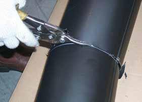
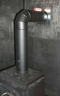
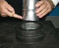
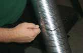
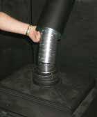
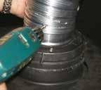
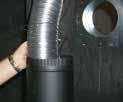
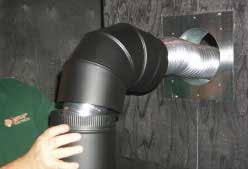
11 installation DIRECT FLUE ZERO CLEARANCE TOP EXIT VERTICAL FLUE KIT INSTALLATION INSTRUCTIONS This flue kit has been manufactured for use with FG39 and to be installed in accordance with AS/NZS To ensure safety and correct unit operation this flue kit must be installed as outlined in these instructions. Heater and flue clearances from combustible materials must be in accordance with these instructions and AS/NZS Part Number: Locate the heater in its proposed position and mark the point for penetration directly above the centre of the heater flue outlet. Check the heater location allows the outer flue to clear all structural timber and combustible surfaces as per the manual. 2. If the enclosure consists of a ceiling cut a 255mm square hole (minimum) for the flue to penetrate, cut hole through roofing material and prepare flashing for termination. 3. Starting at the heater, install first length of inner pipe, crimped end down, using Mill-Pac sealant and self-tapping screws (or rivets). Note first length of inner pipe has a swage only. Inner flue 100mm dia x 900mm x 4 4. Continue assembling flue pipes inner and outer, ensuring each inner join is sealed using Mill-Pac sealant and self-tapping screws (or rivets). Outer flue pipe is to be installed with crimped end up then sealed and fixed together also. Outer Heat Shield 174mm dia x 900mm x 4 1st Length Inner Flue has Deep Crimp and is marked (crimp down) 3 black lengths 5. If required, fix outer flue in the ceiling space using non-combustible bracing to stop movement. On penetration of roof, fit an appropriate flashing or weather seal to suit the roofing material, ensure all joints outside are sealed with appropriate sealer. 6. Fit gas cowl or flomet cap ( ) ensuring inner and outer flue pipes are sealed. 7. Start heater and run for at least 15 minutes to check flue seal. If operational issues are noted, check flue again to ensure proper seal of inner pipe. SUPPLIED Mill-Pac SEALANT MUST BE USED OR WARRANTY WILL BE VOID IF REQUIRED, MORE SEALANT CAN BE PURCHASED USING PART NUMBER Gas cowl part number 46DVA-VCH or Flomet cap part number ( ). SCREWS SUPPLIED FOR INNER FLUE CONNECTION 45º bends (if required) part number Note: if bends are used at the start of flue run, a deeper crimp may be required at the unit for inner pipe fitment. Can be crimped on site and sealed with Mill-Pac sealant and selftapping screws (or rivets). Note It is the installers responsibility to ensure the installation complies with AS/NZS 5601 and all local and building codes. Mill-Pac SEALANT INNER FLUE Screws NOTE: USE A MINIMUM OF 3 SCREWS EQUIDISTANT TO SECURE EVERY INNER FLUE PIPE JOINT AS WELL AS MILL-PAC SEALANT FG39-2 Freestanding Gas Stove 11
12 installation DIRECT FLUE ( ) KIT INSTALLATION DV 1.2m Flue Kit ( ) includes parts needed to install the Freestanding Direct Vent unit with minimu horizontal and vertical vent dimensions. For Installations that require longer vertical dimensions. For installations that require longer vertical and/or horizontal vents, sue the Dura-Vent system as shown in the unit manual. 102mm inside diameter mm 13mm 38mm 38mm 25mm Part # /P 1.2m 12 FG39-2 Freestanding Gas Stove
13 installation 1.2m #8 x 13mm Self Tapping, Stainless Steel #8 x 13mm Self Tapping, Black #8 x 38mm Drill Point, Stainless Steel #8 x 38mm Drill Point, Black #8 x 25mm Wood Screws FG39-2 Freestanding Gas Stove 13


14 FG mm installation #8 X 25mm 241mm x 241mm square hole 241mm x 241mm 610mm vertical 14 FG39-2 Freestanding Gas Stove
15 installation 1.2m 13mm 102mm 13mm FG39-2 Freestanding Gas Stove 15

16 installation mm 13mm to the 102mm dia. flex liner ensuring that 13mm 16 FG39-2 Freestanding Gas Stove


17 installation 13mm A bead of non-hardening silicon sealant should be run around the Astrocap to prevent water from entering and to ensure a tight seal between the cap and the standoff. 13mm 38mm 38mm 13mm a FG39-2 Freestanding Gas Stove 17
18 installation DURA-FLUE TERMINATION Planning Your Dura-Flue Installation There are two basic types of Dura-Flue Room Sealed System installations: horizontal termination and vertical termination. Confirm the maximum horizontal run and maximum vertical rise from the diagrams on page 10. When planning your installation, it will be necessary to select the proper length of flue pipe for your particular requirements. For horizontal installations, determine the minimum clearance from the rear of the unit to the wall. It is also important to note the wall thickness. (The wall thimble is suitable for.6m x 1m or.6m x 2m wall construction.) Select the amount of vertical rise desired for "vertical-to-horizontal" type installations. Warning: Always maintain required clearances (air spaces) to nearby combustibles to prevent a fire hazard. Do not fill air spaces with insulation. The minimum clearance requirements between the outer wall of the flue pipe and nearby combustible surfaces is 32mm. Be sure to check the flue termination clearance requirements from decks, windows, soffits, gas regulators, air supply inlets and public walkways as specified in the Exterior Flue Termination Locations on page 9 and in your local building codes. To determine the length of flue pipe required for vertical installations, measure the distance from the unit flue outlet to the ceiling, the ceiling thickness, the vertical rise in an attic or second storey, and allow for sufficient vertical height above the roof line. For multi-storey applications, fire stops are required at each floor level. If an offset is needed, additional pipe, elbows and supports will be required. Note: These are the minimum pieces required. Other parts may be required for your particular installation. See below for a list of flue parts. If installing termination on a siding covered wall, a vinyl siding standoff or furring strips can be used in order to ensure that the termination is not recessed into siding. The vinyl siding standoff is required for walls with vinyl siding. Minimum components for a Dura-Flue Horizontal Installation: A) Dura-Flue Horizontal Termination Kit B) Wall Thimble (required for combustible walls) Minimum components for a Dura-Flue Vertical Termination: C) Dura-Flue Vertical Termination Kit The Simpson Dura-Flue Room Sealed System offers a complete line of component parts for installation of both horizontal and vertical installation. Many items are offered in decorative black, as well as galvanized finish. The galvanized pipe and fittings are used for concealed locations such as attics or where corrosion is a factor, such as Vertical Terminal Storm Collar Flashing Ceiling Firestop Round Support Box/Wall Thimble Round Support Box/ Wall Thimble above the roof line. Decorative brass trim kits are available for both wall thimbles and ceiling support boxes. Description Horiz. Termination components: 9 0 o black elbow, wall thimble cover, horiz. square termination cap, 1.2m black pipe, 360mm-610mm adjustable black pipe Basic Horiz. Termination Kit includes: 90 o black elbow, wall thimble cover, horiz. square termination cap Vert. Termination Kit includes 0/12-6/12 pitch adjustable flashing, storm collar, low profile term. cap 152mm Pipe Length-Black 229mm Pipe Length-Black 304mm Pipe Length Galv. 304mm Pipe Length-Black 610mm Pipe Length Galv. 610mm Pipe Length-Black 914mm Pipe Length Galv. 914mm Pipe Length-Black 1219mm Pipe Length Galv. 1219mm Pipe Length-Black 219mm - 372mm Adj. Pipe Length-Black 432mm - 610mm Adj. Pipe Length Black 45 O Elbow Galv. 45 O Elbow-Black 45 O Elbow-Swivel Galv. 90 O Elbow-Swivel Galv. Wall Thimble AstroCap Termination Cap Do not exceed the maximum number of elbows. One 90 o for horizontal terminations and two 45 o for vertical termination. DURA-FLUE COMPONENTS You will require the following components with your new Regency Room Sealed Freestanding Gas Stove. Please review your product to make sure you have everything you need. In the flue that you are missing any part, contact your dealer. Pipe Length o 90 Elbow 1.2m Pipe Length Adj.Pipe Length 360mm - 610mm Dura-Flue Basic Horizontal Kit 1 90 o Elbow 1 Wall Thimble Cover 1 Astro Cap 18 FG39-2 Freestanding Gas Stove
19 installation DURA-FLUE HORIZONTAL INSTALLATIONS 45 O Elbow-Swivel-Black 90 O Elbow Galv. 90 O Elbow-Black 90 O Elbow-Swivel Galv. 90 O Elbow-Swivel-Black High Wind Term. Cap (Vertical) Vertical Term. Cap Snorkel-356mm Rise Term.Cap Snorkel-914mm Rise Term.Cap Wall Thimble-Support/Box Cathedral/Ceiling-Support/Box Brass Trim-Wall Thimble/ Ceiling Support Firestop Spacer Flashing 0/12-6/12 Flashing 7/12-12/12 Storm Collar Vinyl Siding Standoff Wall Strap Wall Thimble Flue Guard (Optional) Vinyl Siding Shield Astro Cap two sections are fully locked. The female locking lugs will not be visible from the outside on the Black Pipe or fittings. They may be located by examining the inside of the female ends. Apply sealant "Mill-Pac" to inner pipe and high temp silicone sealant to outer pipe on every twist-lock joint. Hint: Apply silicone to female end. b) Horizontal runs of flue must be supported every three feet. Wall straps are available for this purpose. 3. With the pipe attached to the stove, slide the stove into its correct location, and mark the wall for a 254mm x 254mm (inside dimensions) square hole. The center of the square hole should line up with the centerline of the horizontal pipe, as shown in Diagram 2. Cut and frame the (254mm) square hole in the exterior wall where the flue will be terminated. If the wall being penetrated is constructed of non-combustible material, i.e. masonry block or concrete, a (178mm) diameter hole is acceptable. For External Flue Termination Locations, see Diagram on page If installing the flue termination to a wall with vinyl siding, the Vinyl Siding Standoff must be used. Attach the Vinyl Siding Standoff to the Horizontal Flue Termination, but first run a bead of non-hardening mastic around its outside edges, so as to make a seal between flue cap and the standoff. Install the Vinyl Siding Standoff between the flue cap and the exterior wall and attach with the four wood screws provided. Seal around the Vinyl Siding Standoff on all four sides. Diagram 5. The arrow on the flue cap should be pointing up. Insure that the 32mm clearances to combustible materials are maintained. See Diagram 5. Note: If installing termination on a siding covered wall, a vinyl siding standoff or furring strips must be used to ensure that the termination is not recessed into the siding. The four 1. Set the unit in its desired location. Check to determine if wall studs or roof rafters are in the way when the flueing system is attached. If this is the case, you may want to adjust the location of the unit. 2. Room Sealed pipe and fittings are designed with special twist-lock connections to connect the flueing system to the appliance flue outlet. A twist-lock appliance adaptor is installed on the unit at the factory. Assemble the desired combination of pipe and elbows to the appliance adaptor with pipe seams oriented towards the wall or ceiling, as much out of view as possible. The final positioning of the pipe and 90 o elbow assembly is determined by the mounting orientation of the adaptor on the stove and twist-locked for a solid connection. Note: a) Twist-lock procedure: Four indentations, located on the female ends of pipes and fittings, are designed to slide straight onto the male ends of adjacent pipes and fittings, by orienting the four pipe indentations so they match and slide in to the four entry slots on the male ends (Diagram 1). Push the pipe sections completely together, then twist-lock one section clockwise approximately one-quarter turn, until the Note: a) The horizontal run of flue should have a 6mm rise for every 0.3m of run towards the termination. Never allow the flue to run downward. This could cause high temperatures and may present the possibility of a fire. b) The location of the horizontal flue termination on an exterior wall must meet all local and national building codes, and must not be blocked or obstructed. Diagram 2 Diagram 1 Diagram 5 wood screws provided should be replaced with appropriate fasteners for stucco, brick, concrete, or other types of sidings. 5. Before connecting the horizontal run of flue pipe to the flue termination, slide the black decorative wall thimble cover over the flue pipe, then slide the Wall Thimble (Part # 46DVA-WT) over the flue pipe. 6. Slide the appliance and flue assembly towards the wall carefully inserting the flue pipe into the flue cap assembly. It is important that the flue pipe extends into the flue cap a sufficient distance so as to result in a minimum pipe overlap of 32mm. Secure the connection between the flue pipe and the flue cap using sheet metal screws provided. See Diagram Install the Wall Thimble in the center of the 254mm square and attach with wood screws. 8. Slide the decorative wall thimble up to the wall surface being careful not to scratch the paint and attach with screws provided. Apply decorative brass or chrome trim if desired. See Diagram 7. FG39-2 Freestanding Gas Stove 19 FG39: 1518mm
20 installation Diagram 6 DURA-FLUE VERTICAL TERMINATION 1. Maintain the 32mm clearances (air spaces) to combustibles when passing through ceilings, walls, roofs, enclosures, attic rafter, Diagram 7 or other nearby combustible surfaces. Do not pack air spaces with insulation. Check page 9 for the maximum vertical rise of the flueing system and the maximum horizontal offset limitations. 2. Set the gas appliance in its desired location. Drop a plumb bob down from the ceiling to the position of the appliance flue exit, and mark the location where the flue will penetrate the ceiling. Drill a small hole at his point. Next, drop a plumb bob from the roof to the hole previously drilled in the ceiling, and mark the spot where the flue will penetrate the roof. Determine if ceiling joists, roof rafters or other framing will obstruct the flueing system. You may wish to relocate the appliance or to offset, as shown in Diagram 9 to avoid cutting load bearing members. 3. To install the Round Support Box/Wall Thimble in a flat ceiling, cut a 254mm square hole in the ceiling Diagram 8 centred on the hole drilled in Step 2. Frame the hole as shown in Diagram 10. framing Diagram mm square hole Diagram 9 5. Cut a hole in the roof centred on the small drilled hole placed in the roof in Step 2. The hole should be of sufficient size to meet the minimum requirements for clearance to combustibles of (32mm). Slip the flashing under the shingles (shingles should overlap half the flashing) as per Diagram Continue to assemble pipe lengths. firestop spacer Note: If an offset is necessary in the attic to avoid obstructions, it is important to support the flue pipe every 0.9m, to avoid excessive stress on the elbows, and possible separation. Wall straps are available for this purpose. See Diagram 7. Galvanized pipe and elbows may be utilized in the attic as well as above the roof line. The galvanized finish is desirable above the roof line due to its higher corrosion resistance. Continue to add pipe sections through the flashing until the height of the flue cap meets the minimum height requirements specified in Diagram 12 or local codes. Note that for steep roof pitches, the vertical height must be increased. A poor draft, or down drafting can result from high wind conditions near big trees or adjoining roof lines, in these cases, increasing the flue height may solve the problem. 7. Ensure flue is vertical and secure the base of the flashing to the roof with roofing rails, slide storm collar over the pipe section and seal with a mastic. 8. Install the vertical termination cap by twist locking it. Notes: a) For multistorey vertical installations, a Ceiling Fire stop is required at the second floor, and any subsequent floor. Diagram 13. The opening should be framed to 254mm x 254mm inside dimensions, in the same manner as shown in Diagram 10. Diagram 12 Roof Pitch Minimum Flue Height Meters flat to 7/ over 7/12 to 8/ over 8/12 to 9/ over 9/12 to 10/ over 10/12 to 11/ over 11/12 to 12/ over 12/12 to 14/ over 14/12 to 16/ over 16/12 to 18/ over 18/12 to 20/ over 20/12 to 21/ b) Any occupied areas above the first floor, including closets and storage spaces, through which the vertical flue passes, must be enclosed. 4. Assemble the desired lengths of black pipe and elbows necessary to reach from the appliance adaptor up though the Round Support Box. Insure that all pipes and elbow connections are in the fully twist-locked position and sealed. Diagram 11: The upper half of the flashing is installed under the roofing material and not nailed down until the chimney is installed. This allows for small adjustments. 20 FG39-2 Freestanding Gas Stove
21 installation CATHEDRAL CEILINGS Round Support (RDS) & Square Support (SQS) If your home has a cathedral ceiling (no attic space between the ceiling and the roof), install the chimney and support as follows. nails Ceiling Firestop 32mm Min. Diagram 13 Offset Chart Offset mm mm Min. 32mm Min. 32mm Min. GS 152mm Nominal Diameter ID Pipe Length (L) mm Height mm Place the support in the opening. Lower it to the correct height as determined by the table and diagram below. Using a level, make sure the support is vertical. If the support extends above the roof, cut it flush with the top of the roof. Nail the support to the frame opening using (8) 76mm spiral nails or #8 x 38mm screws. Note: If you are using a 152mm square support you may find it difficult to screw it in place because it is fairly small inside. Simpson Dura-Flue has provided angle brackets with this support which can be screwed to the outside of the support box and nailed to surrounding framing as required. Use a minimum of four #8 x 13mm screws per bracket. In some cases these Slope "X" 0/12-2/12 102mm 2/12-7/12 140mm 7/12-12/12 172mm 12/12-24/12 191mm 24/ mm 5. Ensure flue is vertical and secure flashing to the roof with roofing nails. Slide the storm collar over the pipe section and seal with a mastic. 6. Twist lock the flue cap on to the last section. Support Extensions - Round (RDSE) or Square (SQSE) Steep pitched cathedral ceilings may require the use of a support extension. This piece fits down inside the support and can be adjusted to increase the support's length by up to 559mm. The extension is attached to the support using the eight metal screws provided. Be sure there is at least a 51mm overlap where the extension joins the support. L Height brackets may need to be trimmed (e.g.: to fit under a flashing). Place the Finish Collar around the support and fasten it to the ceiling using the screws provided. Offset 1. Situate the chimney in a convenient location as near as possible to the appliance outlet. Cut and frame a hole in the roof for the support. The sides of this hole must be vertical with 32mm clearance. 3. Use appropriate roof flashing. Place the flashing under the upper shingles and on top of the lower shingles approximately half of the flashing should be under the shingles. 4. Assemble the desired lengths of Black Pipe and Elbows necessary to reach from the appliance adaptor up through the support box and flashing to proper height as per Dia. 12, local codes or page 9. Ensure that all pipe and elbow connections are in their fully twist lock position. FG39-2 Freestanding Gas Stove 21
22 EV1 EV2 R.Q. ADJ Pin P.OUT installation GAS CONNECTION The gas line should be rigid pipe. Copper may also be used if approved by AS/NZS The gas connection at the valve is 1/2 male. For minimum and maximum supply pressure see the System Data Table. GAS PIPE PRESSURE TESTING The appliance must be isolated from the gas supply piping system by closing its individual manual shut-off valve during any pressure testing of the gas supply piping system at test pressures equal to or less than 3.45 kpa. Disconnect piping from valve at pressures over 3.45 kpa. The manifold pressure is controlled by a regulator built into the gas control, and should be checked at the pressure test point. Note: To properly check gas pressure, both inlet and manifold pressures should be checked using the valve pressure ports on the valve. 1. Make sure the valve is in the "OFF" position. 2. Loosen the "IN" (# 3) and/or "OUT" (# 4) pressure tap(s), turning counterclockwise with a 3mm wide flat screwdriver. 3. Attach manometer to "IN" and/or "OUT" pressure tap(s) using a 8mm ID hose. 4. Seal and or check the pilot outlet (# 8) 5. The pressure check should be carried out with the unit burning and the setting should be within the limits specified on the safety label. 6. When finished reading manometer, turn off the gas valve, disconnect the hose and tighten the screw (clockwise) with a 3mm flat screwdriver. Screw should be snug, but do not over tighten. SIT 845 VALVE DESCRIPTION 1) On-Off Solenoid Valve EV1 2) On-Off Solenoid Valve EV2 3) Inlet Pressure Test Point 4) Outlet Pressure Test Point 5) Connection for Pressure Regulator / Combustion Chamber Compensation 6) Pressure Regulator for Minimum and Maximum Outlet Pressure 7) Gas Outlet Pressure Electric Modulator 8) Pilot Outlet 9) Main Gas Outlet 10) Side Outlet 11) Main Gas Inlet 2 AERATION ADJUSTMENT The burner aeration is factory set but may need adjusting due to either the local gas supply or altitude. NG LPG MD Fully Open Fully Open System Data Burner Inlet Orifice Sizes: NG LPG Burner #32 # mm 1.78mm Max. Input NG LPG Min. Input NG LPG Supply Pressure NG LPG 40 Mj/h 38 Mj/h 20 Mj/h 19 Mj/h min kpa min kpa Manifold Pressure NG.94 kpa LPG 2.55kPa Caution: Carbon will be produced if the air shutter is closed too much. Note: Any damage due to carboning resulting from improperly setting the aeration controls is NOT covered under warranty. 22 FG39-2 Freestanding Gas Stove


23 installation Conversion Kit for NG to LPG Part # THIS CONVERSION MUST BE DONE BY A QUALIFIED GAS FITTER IF IN DOUBT DO NOT DO THIS CONVERSION!! Conversion Kit contains: Qty. Part # Description m Allen Key Burner Orifi ce # "Converted to LPG" label Orange "Propane" label #30 LP Pilot Orifi ce Instruction Sheet 6. Pull out the pilot hood by hand. Pilot Hood 8. Put in the new LPG orifi ce with the Allen key. Then put back the pilot hood. 1. Shut off the gas supply and unplug the power cord. 2. Open the front door and carefully remove the logs and lava rock. 3. Remove burner. 4. Remove burner orifice with a 13mm wrench and discard. Use a wrench to hold on to the elbow behind the orifice. 5. Reinstall new burner orifi ce LPG stamped #50 and tighten. Pilot Hood removed Pilot Orifi ce 9. Place the pilot hood back on. 7. Remove the pilot orifi ce with the Allen key. Burner Orifi ce 10. Adjust the burner aeration setting to fully open and install the burner. 11. Remove the pedestal back cover by removing the 4 Phillips screws. FG39-2 Freestanding Gas Stove 23


 blocked, screw in the screw (C) to increase the pressure and screw it out to decrease it. Use a screwdriver 6 x 1 blade.")

 to increase the outlet pressure and screw it out to decrease it. Use a 10 mm wrench.")

24 installation 12. Stick the conversion label "This unit has been converted to LPG" over top of the serial number decal. 13. Replace the yellow "NG" label with the red "LPG" label. 14. Carefully pull out the control box. Note: The control box is held in place by velcro. 15. Remove the control box cover by undoing the 3 screws. Maneuver through antenna. 17. Stick the conversion label "This unit has been converted to LPG" on the control box cover. 18. Reverse steps 15, 14 & Open the bottom door and remove the front panel by undoing the 6 screws. Minimum pressure: Remove one of the cables connected to the electric modulator. Keeping the nut (B) blocked, screw in the screw (C) to increase the pressure and screw it out to decrease it. Use a screwdriver 6 x 1 blade. NOTE: The outlet pressure must be set to minimum 0.74 kpa. Cable Electric Modulator Antenna Control Box Cover 16) Remove the jumper using a plier. Jumper Jumper Location 20. Turn on the gas supply and plug in the power cord. 21. Adjusting the Outlet Pressure All the adjustments must be carried out in the following order: Remove the modulator plastic cap (A) using needle nose pliers. Maximum pressure: Turn the unit ON to its highest input rating. Screw in the nut (B) to increase the outlet pressure and screw it out to decrease it. Use a 10 mm wrench. NOTE: The outlet pressure must be set to maximum 2.55 kpa. After carrying out all adjustments, block the setting screws with paint, taking care not to obstruct the breather orifice of the pressure. Put back the modulator plastic cap. WARNING: To ensure the correct operation of the modulator it is necessary that the plastic cap (A) is returned to its original location. B 22. At the end of all setting and adjustment operations, check electrical insulation and gas leaks. 23. Reverse step 19. A C 24. Check operation of fan and flame control. 25. Check for proper fl ame appearance and glow on logs. Installer Notice: These instructions must be left with the appliance. 24 FG39-2 Freestanding Gas Stove


25 installation LOG SET INSTALLATION Read the instructions below carefully and refer to the diagrams. If logs are broken do not use the unit until they are replaced. Broken logs can interfere with the pilot operation. 3. Install Log A onto the 2 pins on the rear log bracket -- in locations shown below. A The gas log kit contains the following: A Rear Log B Middle Left Log C Front Right Log D Front Left Log E Middle Left 'Y' Log F Center Upright Log G Middle Right Log Lava Rock, Pins on Rear Log Support 4. Install Log B onto the 2 pins on the burner in locations shown below. Note: Install Optional Brick Panels prior to installing logs. B A G Log B Pins B E D F C Log ID B 1. Carefully remove the logs from the box and unwrap them. The logs are fragile, handle with care - do not force into position. 2. Place the Lava rock on either side of the burner - DO NOT place lava rock anywhere on the actual burner. Log B in position 5. Install Log C onto the 2 pins on the burner in locations shown below. C Lava Lava Log C Pins FG39-2 Freestanding Gas Stove 25


 onto the pin on Log")


26 installation C F Log C in position 6. Install Log D onto the 2 pins on the burner in locations shown below. Log F in position 9. Install Log G--top end sits in the notch at the top of Log F and the bottom end of Log G rests against the bracket on the burner as shown. D G Log D install 7. Install Log E (Y shaped Log) onto the pin on Log B--set the other end of Log E on the burner. F Notch Log G install E G Log E install 8. Install Log F across Log C as shown, Log F will rest in a flat spot on Log C. Log G onto bracket Bracket 10. Test fire to ensure proper light off (make sure flame flows smoothly from one end of burner to the other. If there is any flame hesitation, check that area for any blockage of the burner port. F C Log F install Completed Install 26 FG39-2 Freestanding Gas Stove

27 FRONT DOOR INSTALLATION (packaged separately) 1. Open the two side panels. 2. Slide the door onto the two hinge pins making sure the two pieces are flush together. See Diagram 1. Diagram 1 3. Close the door. The latch plate must be centered around the alignment pin. See Diagram 2. If the latch plate interferes with the corner of the stove you may want to angle the plate slightly so the door closes easier. 5. Remove the blue plastic protective coating from the glass. 6. Test the seal around the door by placing a piece of paper between the unit and the door, close the door and try to pull the paper out. If it slips out easily, then the door is not properly sealed. Tighten or loosen the latch. See Diagram 3. Note: The door latch may require adjustment as the door gasket material compresses after a few fires and after glass replacement. Turn the latch catch inward or outward to loosen or tighten. OPTIONAL REMOTE CONTROL Use the Regency Remote Control Kit (Part # ) approved for this unit. Use of other systems may void your warranty. The remote control kit comes with a hand held transmitter and a wall mounting plate. 1. Choose a convenient location to mount the hand held transmitter, protection from extreme heat is very important. The remote can also be used as a wall thermostat. FINAL CHECK installation Before leaving this unit with the customer, the installer must ensure that the appliance is firing correctly. This includes: 1. Clocking the appliance to ensure the correct firing rate (rate noted on label) at 15 minutes. 2. If required, adjusting the primary air to ensure that the flame does not carbon. First allow the unit to burn for 15 min. to stabilize. 3. Check for proper draft. CAUTION Any alteration to the product that causes sooting or carboning that results in damage to the exterior facia is not the responsibility of the manufacturer. Diagram 2 4. The latches should already be at the proper setting. If they are too hard or too easy to close, you may want to adjust them by loosening the latch catch. See Diagram 3. Diagram 3 FG39-2 Freestanding Gas Stove 27
28 installation WIRING This heater does not require a 240V A.C. supply for the gas control to operate. A 240V A.C. power supply is needed for the fan/blower operation. Caution: Ensure that the wires do not touch any hot surfaces and are away from sharp edges. CAUTION: Label all wires prior to disconnection when servicing controls. Wiring errors can cause improper and dangerous operation. WARNING: Electrical Grounding Instructions This appliance is equipped with a three pronged (grounding) plug for your protection against shock hazard and should be plugged directly into a properly grounded three-prong receptacle. Do not cut or remove the grounding prong from this plug. 28 FG39-2 Freestanding Gas Stove
 Check to see that all wiring is correct and enclosed to prevent possible shock. 3) Check to ensure there are no gas leaks.")
29 operating instructions OPERATING INSTRUCTIONS Before operating this appliance, proceed through the following check list. 1) Read and understand these Instructions before operating this appliance. 2) Check to see that all wiring is correct and enclosed to prevent possible shock. 3) Check to ensure there are no gas leaks. 4) Never operate the appliance with the glass removed or with the door open. 5) Verify that all flueing and the cap is unobstructed. 6) Verify log placement. LIGHTING INSTRUCTIONS 1) Plug the power cord into a power outlet. 2) Press and release the ON/OFF button once to start the unit. 3) After approximately 3 seconds the spark ignition system will spark for 40 seconds to light the main burner. 4) If the main burner does not light, reset the unit. RESETTING THE UNIT 1) Open the pedestal door on the unit. 2) Press and release the reset button, located on the unit's control panel once. 3) Wait for approximately 3 seconds and the pilot sparks can be heard and seen. It would take 2 to 3 seconds for the flame to be lit. NOTE: A period of 30 seconds must pass before another reset is attempted. SHUTDOWN INSTRUCTIONS 1) Press the ON/OFF button once. 2) Turn off all electric power to the appliance if service is to be performed. FIRST FIRE The FIRST FIRE in your heater is part of the paint curing process. To ensure that the paint is properly cured, it is recommended that you burn your fireplace for at least four (4) hours the first time you use it with the fan on. When first operated, the unit will release an odour caused by the curing of the paint and the burning off of any oils remaining from manufacturing. Smoke detectors in the house may go off at this time. Open a few windows to ventilate the room for a couple of hours. The glass may require cleaning. NOTE: The main burner will always start on "HIGH" and resume it's last setting after 20 seconds of operation. NOTE: When the glass is cold and the appliance is lit, it may cause condensation and fog the glass. This condensation is normal and will disappear in a few minutes as the glass heats up. DO NOT ATTEMPT TO CLEAN THE GLASS WHILE IT IS STILL HOT! DO NOT BURN THE APPLIANCE WITH- OUT THE GLASS FRONT IN PLACE. FAN OPERATION Set the fan speed on the control panel located in behind the pedestal door to adjust fan to the desired speed. Control Panel Pressing and releasing the plus (+) FAN button will change the fan speed as follows: OFF -> LOW -> MEDIUM -> HIGH -> OFF, etc. Pressing and releasing the minus (-) FAN button will be the reverse of the above. ADJUSTING FLAME HEIGHT There are six flame settings that can be adjusted by pressing and releasing the plus (+) and minus (-) FLAME button. The FLAME setting button is located on the control panel in behind the pedestal door. FG39-2 Freestanding Gas Stove 29
30 operating instructions SUMMARY OF CONTROLS On/Off Button If the unit is switched off, pressing and releasing this button once will switch the unit on. The unit will resume its last settings. If the unit is switched on, pressing and releasing this button once will switch the unit off. Flame: Increase - If the unit is switched on, pressing and releasing the flame plus (+) button once will increase the flame height to the next available high setting. Decrease - If the unit is switched on, pressing and releasing the flame minus (-) button once will decrease the flame height to the next available low setting. Fan: Increase - If the unit is switched on, pressing and releasing the fan plus (+) button once will increase the fan speed to the next available high setting. Decrease - If the unit is switched on, pressing and releasing the fan minus (-) button once will decrease the fan speed to the next available low setting. PILOT ADJUSTMENT Periodically check the pilot flames. The correct flame pattern has 3 strong blue flames. One flowing around the Flame Sensor, the second flowing across the burner (it does not have to be touching the burner) and the third flame flowing tangent to the spark ignitor. NOTE: If you have an incorrect flame pattern, contact your Regency dealer for further instructions. An incorrect flame pattern will have small, probably yellow flames, not coming into proper contact with the rear of the burner or thermopile. NORMAL OPERATING SOUNDS OF GAS APPLIANCES It is possible that you will hear some sounds from your gas appliance. This is perfectly normal due to the fact that there are various gauges and types of steel used within your appliance. Listed below are some examples. All are normal operating sounds and should not be considered as defects in your appliance. Fan: Regency gas appliances use high tech fans to push heated air farther into the room. It is not unusual for the fan to make a "whirring" sound when ON. This sound will increase or decrease in volume depending on the speed setting of your fan speed control. Burner Tray: The burner tray is positioned directly under the burner tube(s) and logs and is made of a different gauge material from the rest of the firebox and body. Therefore, the varying thicknesses of steel will expand and contract at slightly different rates which can cause "ticking" and "cracking" sounds. You should also be aware that as there are temperature changes within the unit these sounds will likely re-occur. Again, this is normal for steel fireboxes. Gas Control Valve: As the gas control valve turns ON and OFF, a dull clicking sound may be audible, this is normal operation of a gas regulator or valve. Unit Body/Firebox: Different types and thicknesses of steel will expand and contract at different rates resulting in some "cracking" and "ticking" sounds will be heard throughout the cycling process. 30 FG39-2 Freestanding Gas Stove
31 operating instructions COPY OF THE LIGHTING PLATE INSTRUCTIONS, AS/NZS 5601 WARNING: DO NOT SPRAY AEROSOLS IN THE VICINITY OF THIS APPLIANCE WHILE IN OPERATION. FG39-2 Freestanding Gas Stove 31
32 maintenance MAINTENANCE INSTRUCTIONS Any maintenance required accessing the glass door of the unit must be performed by an authorised service person. 1. Always unplug the power cord before cleaning. For relighting, refer to lighting instructions. Keep the burner and control compartment clean by brushing and vacuuming at least once a year. When cleaning the logs, use a soft clean brush as the logs are fragile and easily damaged. 2. Clean glass (never when unit is hot), appliance, louvres, and door with a damp cloth. Never use an abrasive cleaner. The gold louvres (and optional gold door) may be scratched if abrasives are used to clean them. The heater is finished in a heat resistant paint and should only be refinished with heat resistant paint (not with wall paint). Regency uses StoveBright Paint - Metallic Black # Make a periodic check of burner for proper position and condition. Visually check the flame of the burner periodically, making sure the flames are steady; not lifting or floating. If there is a problem, call an authorised service person. 4. The appliance and flueing system must be inspected before use, and at least annually, by an authorised field service person, to ensure that the flow of combustion and ventilation air is not obstructed. During the annual service call, the burners should be removed from the burner tray and cleaned. Replace the embers - do not block the pilot or burner ports. 5. Keep the area near the appliance clear and free from combustible materials, gasoline and other flammable vapours and liquids. WARNING: CHILDREN AND ADULTS SHOULD BE ALERTED TO THE HAZARDS OF HIGH SURFACE TEMPERATURE AND SHOULD STAY AWAY TO AVOID BURNS OR CLOTHING IGNITION. YOUNG CHILDREN SHOULD BE CAREFULLY SUPERVISED WHEN THEY ARE IN THE SAME ROOM AS THE APPLIANCE. CAUTION: ANY SAFETY SCREEN OR GUARD REMOVED FOR SER- VICING AN APPLIANCE MUST BE REPLACED PRIOR TO OPERAT- ING THE APPLIANCE. CLOTHING OR OTHER FLAM- MABLE MATERIAL SHOULD NOT BE PLACED ON OR NEAR THE APPLIANCE. DO NOT USE THIS APPLIANCE IF ANY PART HAS BEEN UNDER WATER. IMMEDIATELY CALL AN AUTHORIZED SERVICE TECHNI CIAN TO INSPECT THE APPLI- ANCE AND TO REPLACE ANY PART OF CONTROL SYSTEM AND ANY GAS CONTROL WHICH HAS BEEN UNDER WATER. 6. Verify proper operation after servicing. LOG REPLACEMENT The unit should never be used with broken logs. Turn off the gas valve and allow the unit to cool before opening door to carefully remove the logs. The pilot light generates enough heat to burn someone. If for any reason a log should need replacement, you must use the proper replacement log. The position of these logs must be as shown in the diagram under Log Installation. Note: Improper positioning of logs may create carbon build-up and will alter the unit s performance which is not covered under warranty. DOOR GASKET If the door gasket requires replacement use 22mm diameter oval door gasket. LATCH ADJUSTMENT The door latch may require adjustment as the door gasket material compresses after a few fires and after glass replacement. Turn the adjustable catch to tighten or loosen the latch. 32 FG39-2 Freestanding Gas Stove
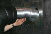
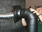
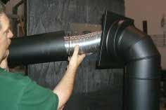
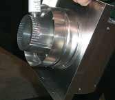
33 GLASS REPLACEMENT Your Regency heater is supplied with high temperature, 5mm Neoceram silica coated ceramic glass that will withstand the highest heat that your unit will produce. In the event that you break your glass, purchase your replacement from an authorised Regency dealer only, and follow the step-by-step instructions for replacement. Removing Glass: Note: Wearing gloves will protect your hands while handling glass. 1. Remove the door from the unit and place on a soft surface to prevent scratching. 2. Pull out the door gasket. 3. Remove the 24 nuts holding the glass retainers in place. Do not remove the nuts underneath the retainers. 4. Remove the door catch plate. FAN MAINTENANCE If your fan requires maintenance or replacement, access to the fan is through the plate on the rear wall of the firebox. NOTE: the unit MUST NOT be operated without the fan access panel securely in place and correctly sealed. If the fan is damaged or needs repair, it shall be repaired by the manufacturer or its service agent or similarly qualified person to avoid a hazard. IMPORTANT: These fans collect a lot of dust from within your home. Ensure you maintain these fan motors on a regular basis by vacuuming out the fan squirrel cages, around the motor, and around the grills on the back of the stove. IMPORTANT Disconnect power supply before servicing Alternate Fan Access: If the rear access cover is accessible, it can be removed to provide access to the fan. maintenance 13mm 22mm 5. Lift fan off of the 2 pins, tip back and pull through firebox opening. Disconnect the green ground wire from the right side of the fan as soon as you can reach it. 5. Remove glass retainers on sides first (3 each side) then remove two center retainers. 6. Remove glass from door assembly. When removing glass, leave white insulation in place. 7. Reverse steps 6-2. WARNING: Electrical Grounding Instructions This appliance is equipped with a three pronged (grounding) plug for your protection against shock hazard and should be plugged directly into a properly grounded three-prong receptacle. Do not cut or remove the grounding prong from this plug. Grommet Rear Stove Wall Pin Fan Unclip these 2 wires Pin Fan Access Panel Access Panel Gasket FAN REMOVAL 1. Unplug or disconnect power source to stove. 2. Remove all logs and the rear log support, then remove the 10 screws holding the access panel in place. 3. Unclip the black and white wires from the fan motor. 4. Open both side doors and gently pull the flex pipe away from the center, otherwise the fan can catch on the flex pipe during installation and tear the pipe. Do not tear or damage the flex pipe. FAN REPLACEMENT Reverse the above steps (1-5). If necessary install a new gasket before replacing the fan access panel. Make sure the fan wires and the ground wire are reattached. Hint for pushing fan down onto pins - rub a bit of dish soap on the grommet so it will slide more easily onto the pin. Check to make sure the fan is seated properly on the pins - try to move the fan back and forth, there should be no noise, if there is check that the grommets haven't come loose. FG39-2 Freestanding Gas Stove 33


34 maintenance REMOVING VALVE TRAY If your valve requires maintenance or replacement, follow these instructions: NOTE: Always shut off the gas and disconnect the power supply before removing the valve. 1. Open the front door and carefully remove the logs and lava rock. 2. Remove the burner by removing the two 6mm hex head screws. See diagram below. 4. Remove the two outside frame pieces by removing two screws per side. See diagram below. 7. Disconnect the gas pipe line at the valve. 8. Remove the pedestal back cover by removing the 4 Philips screws. 9. Disconnect the 5 pin molex connector. 10. Disconnect the ground wires. 5. Remove the front plate by undoing the 6 screws. 5 Pin Molex Connector Ground Wire 11. Remove the 20 x 5 mm hex head screws holding the burner tray assembly in place. 3. Open the front pedestal door and unhook chain. You may want to put a soft cloth on the base of the unit so that when the pedestal door is open it doesn't scratch the paint. See diagram below. 12. Carefully lift the burner tray assembly out. 13. To replace the burner tray assembly, reverse these instructions. 6. Disconnect the manual switch cable and reset cables. Manual Switch Cable Reset Cables 34 FG39-2 Freestanding Gas Stove
 910-082 910-089 910-088 910-084 911-101 910-526 910-080 910-912 910-521, 910-522, 910-523 911-183 910-083 911-121 910-514 FG38 FG39 PG33 PG36 / PG36D PG121/ PG131")
35 PARTS parts LIST list ELECTRONIC COMPONENTS PARTS LIST Note: Depending on the model, the diagram below may not be exactly as shown - for reference purposes only (Not exactly as shown) , , FG38 FG39 PG33 PG36 / PG36D PG121/ PG131 GFI300L IG34 GF900L/C GF1500L Fan Resistor Intermittent Pilot N/A N/A N/A N/A Intermittent Pilot N/A N/A N/A N/A N/A N/A N/A Intermittent Pilot N/A N/A N/A N/A N/A N/A N/A N/A Direct Spark Ignitor N/A N/A N/A N/A N/A N/A N/A N/A Flame Cable N/A N/A N/A N/A N/A N/A N/A N/A Spark Cable N/A N/A N/A N/A N/A N/A N/A N/A Control Box N/A N/A N/A Control Box N/A N/A N/A N/A N/A N/A Manual Control Switch N/A N/A N/A N/A N/A N/A Valve Control Box Cable (1) Control Box Cable (2) Control Box Cable (3) Control Box Cable (4) Ignition Module to Valve Cable *N/A (2) (1) (1) (3) N/A (2) N/A N/A N/A N/A Reset Switch N/A Ignition Module (1) Ignition Module (2) (1) (2) (2) (2) (2) (2) (2) (2) (2) (2) Jumper Wire N/A Manual Control Switch N/A N/A N/A N/A N/A **Note: The Control Box Cable wires for the FG38 come separately: , , , , FG39-2 Freestanding Gas Stove 35
Manual FOR YOUR SAFETY
 Owners & Installation Freestanding Gas Stove Manual LISTINGS AND CODE APPROVALS These gas appliances have been tested in accordance with AS4553, NZS 5262 and have been certified by the Australian Gas Association
5"x 8" DIRECT VENT INSTALLATION INSTRUCTIONS FOR DECORATIVE GAS APPLIANCES AND DIRECT VENT HEATERS APPLICATION
 5"x 8" DIRECT VENT INSTALLATION INSTRUCTIONS FOR DECORATIVE GAS APPLIANCES AND DIRECT VENT HEATERS APPLICATION These instructions apply to the Simpson Dura-Vent 5"x 8" Direct Vent System. This venting
Panorama PG36 Gas Log Fireplace. Manual
 Owners & Installation Panorama PG36 Gas Log Fireplace Manual LISTINGS AND CODE APPROVALS These gas appliances have been tested in accordance with AS4553, NZS 5262 and have been certified by the Australian
Panorama PG33 Gas Inbuilt
 Owners & Installation Manual Panorama PG33 Gas Inbuilt Models: PG33NG4-R PG33LPG4-R PLEASE KEEP THESE INSTRUCTIONS FOR FUTURE REFERENCE LISTINGS AND CODE APPROVALS These gas appliances have been tested
Manual. PG33 Gas Inbuilt. Owners & Installation PLEASE KEEP THESE INSTRUCTIONS FOR FUTURE REFERENCE. Models: PG33-NG PG33-LPG
 Owners & Installation Manual LISTINGS AND CODE APPROVALS These gas appliances have been tested in accordance with AS4553AG 103, NZS 5262 and have been certified by the Australian Gas Association for installation
PG33 Gas Inbuilt. Manual
 Owners & Installation Manual LISTINGS AND CODE APPROVALS These gas appliances have been tested in accordance with AS4533-2000, NZS 5262 and have been certifi ed by the Australian Gas Association for installation
Manual. Owners & Installation. Zero Clearance Room Sealed Gas Fireplace PLEASE KEEP THESE INSTRUCTIONS FOR FUTURE REFERENCE
 Owners & Installation Manual LISTINGS AND CODE APPROVALS These gas appliances have been tested in accordance with AG 103, NZS 5262 and have been certified by the Australian Gas Association for installation
Manual. P36D Gas Log Fireplace. Owners & Installation PLEASE KEEP THESE INSTRUCTIONS FOR FUTURE REFERENCE. Models: P36D-NG2 P36D-LPG2
 Owners & Installation P36D Gas Log Fireplace Manual LISTINGS AND CODE APPROVALS These gas appliances have been tested in accordance with AS4553, NZS 5262 and have been certified by the Australian Gas Association
Manual. Owners & Installation. Panorama PG121/PG131 Gas Fireplace PLEASE KEEP THESE INSTRUCTIONS FOR FUTURE REFERENCE
 Owners & Installation Manual LISTINGS AND CODE APPROVALS These gas appliances have been tested in accordance with AS4553, NZS 5262 and have been certified by the Australian Gas Association for installation
Gas Stoves. H15-10 Direct Vent Gas Stove. Model H15-NG10 H15-LP10. Approved Venting Systems
 H15-10 Direct Vent Gas Stove Model H15-NG10 H15-LP10 Fuel Type Natural Gas Propane Minimum Supply Pressure 5.0 W.C. (1.25 kpa) 12.0 W.C. (3.00 kpa) Manifold Pressure - High 3.8 W.C. (0.95 kpa) 11 W.C.
Manual. Direct Vent Gas Fireplace. Owners & Installation PLEASE KEEP THESE INSTRUCTIONS FOR FUTURE REFERENCE. Models: HG35-NG HG35-LPG
 Owners & Installation Manual LISTINGS AND CODE APPROVALS These gas appliances have been tested in accordance with AG 103, NZS 5262 and have been certified by the Australian Gas Association for installation
P P Gas Fireplace. P See Thru
 P121-10 - P131-10 Gas Fireplace Model P121/P131-NG10 P121/P131-LP10 Fuel Type Natural Gas Propane Minimum Supply Pressure 5 W.C. (1.25 kpa) 12 W.C. (3.00 kpa) Manifold Pressure - High 3.8 W.C. (0.95 kpa)
Gas Stoves. C34-10 Direct Vent Gas Stove. Side wall E F. Back wall F E. Model C34-NG10 C34-LP10
 Back wall Gas Stoves Model C34-NG10 C34-LP10 Fuel Type Natural Gas Propane Minimum Supply Pressure 5.0 W.C. (1.25 kpa) 12.0 W.C. (3.00 kpa) Manifold Pressure - High 3.8 W.C. (0.95 kpa) 11 W.C. (2.74 kpa)
Greenfire GF950L Gas Fireplace
 Greenfire GF950L Gas Fireplace Owners & Installation Manual MODELS: GF950L-NG GF950L-LP GF950L-ULPG LISTINGS AND CODE APPROVALS These gas appliances have been tested in accordance with AS 5263.0, AS/NZS
Manual. P36 Gas Inbuilt Calais / Grenada. Owners & Installation PLEASE KEEP THESE INSTRUCTIONS FOR FUTURE REFERENCE. Models: P36-NG3 P36-LPG3
 Owners & Installation Manual LISTINGS AND CODE APPROVALS These gas appliances have been tested in accordance with AG 103, NZS 5262 and have been certified by the Australian Gas Association for installation
H35 Direct Vent Gas Stove. 17,500 BTU/h (5.13 kw) 34,000 BTU/h (9.97 kw) 15,000 BTU/h (4.39 kw) 28,500 BTU/h (8.35 kw)
 34,000 BTU/h (9.97 kw) 15,000 BTU/h (4.39 kw) 28,500 BTU/h (8.35 kw)") H35 Direct Vent Gas Stove Model H35-NG10 H35-LP10 Fuel Type Natural Gas Propane Minimum Supply Pressure 5.0 W.C. (1.25 kpa) 12.0 W.C. (3.00 kpa) Manifold Pressure - High 3.8 W.C. (0.94 kpa) 11 W.C. (2.74
H35 Direct Vent Gas Stove Model H35-NG10 H35-LP10 Fuel Type Natural Gas Propane Minimum Supply Pressure 5.0 W.C. (1.25 kpa) 12.0 W.C. (3.00 kpa) Manifold Pressure - High 3.8 W.C. (0.94 kpa) 11 W.C. (2.74
Greenfire GF1500L Gas Fireplace
 Greenfire GF1500L Gas Fireplace Owners & Installation Manual MODELS: GF1500L-NG GF1500L-LP GF1500L-ULPG LISTINGS AND CODE APPROVALS These gas appliances have been tested in accordance with AS4553 / NZS5262
Geneva FOR YOUR SAFETY
 Owners & Installation Manual LISTINGS AND CODE APPROVALS These gas appliances have been tested in accordance with AG 103, NZS 5262 and have been certified by the Australian Gas Association for installation
BDM Direct Vent systems are for use with direct vent gas fired appliances.
 INSTALLATION INSTRUCTIONS Pro-Form DIRECT VENT SYSTEM Tested to ANSI Z21.88-2009 /CSA 2.33-2009 REPORT # 369-P-02b-6.5 Read through all venting and appliance instructions before beginning your installation.
USERS INSTALLATION OPERATION and MAINTENANCE MANUAL. Installer: Please leave this manual with the appliance owner for future reference
 Optima 45-3 Direct Vent Free Standing Gas Heater For use with Natural Gas or Propane* WARNING: If the information in this manual is not followed exactly, fire or explosion may result causing property damage,
WARNING: Improper installation, adjustment, alteration, service or maintenance can cause injury or property damage. Refer to this manual.
 Malm Fireplaces, Inc. 368 Yolanda Avenue - Santa Rosa, Ca 95404 (707) 523-7755 - Fax: (707) 571-8036 info@malmfireplaces.com 34 Zircon Direct Vent Tested & Listed by LabTest Certified for use in USA &
MODELS: H25-NG Natural Gas H25-LP Propane FOR YOUR SAFETY
 www.hampton-fire.com H25 Direct Vent Gas Fireplace Owners & Installation Manual WARNING: If the information in these instructions are not followed exactly, a fire or explosion may result causing property
 www.excalibur-fire.com P95-2 Zero Clearance Direct Vent Gas Fireplace Owners & Installation Manual MODELS: P95-NG2 Natural Gas WARNING: If the information in these instructions are not followed exactly,
Greenfire GFi350L Gas Inbuilt
 Owners & Installation Greenfire GFi350L Gas Inbuilt Manual Models: GFi350LNG-R GFi350LLP-R GFi350LULPG-R PLEASE KEEP THESE INSTRUCTIONS FOR FUTURE REFERENCE LISTINGS AND CODE APPROVALS These gas appliances
MODELS LFP4218/LFP6018 TOP VENT GAS FIREPLACE
 MODELS LFP4218/LFP6018 TOP VENT GAS FIREPLACE PFS APPROVED FOR NATURAL GAS OR PROPANE GAS Z21.50-2014 If your plans do not allow for the venting system as outlined previously in the installing chimney/vent
Greenfire GF1500LST Gas Fireplace
 Greenfire GF1500LST Gas Fireplace Owners & Installation Manual MODELS: GF1500LST-NG GF1500LST-LP GF1500LST-ULPG LISTINGS AND CODE APPROVALS These gas appliances have been tested in accordance with AS4553
Manual. G51 Surefire. Owners & Installation PLEASE KEEP THESE INSTRUCTIONS FOR FUTURE REFERENCE. Models: G51-NG G51-LPG
 Owners & Installation Manual LISTINGS AND CODE APPROVALS These gas appliances have been tested in accordance with AG 103, NZS 5262 and have been certified by the Australian Gas Association for installation
Optima 72 USERS INSTALLATION OPERATION AND MAINTENANCE MANUAL. Gas Fired Vented Room Heater (Direct Vent) For use with natural gas or propane*
 For use with natural gas or propane*") Optima 72 Gas Fired Vented Room Heater (Direct Vent) For use with natural gas or propane* For serial #39959 and up WARNING: If the information in this manual is not followed exactly, fire or explosion
Optima 72 Gas Fired Vented Room Heater (Direct Vent) For use with natural gas or propane* For serial #39959 and up WARNING: If the information in this manual is not followed exactly, fire or explosion
TAMARRON HEAT RECIRCULATIVE GAS FIREPLACE
 INSTALLATION AND OPERATING INSTRUCTIONS TAMARRON HEAT RECIRCULATIVE GAS FIREPLACE MODEL : TR42 NG Natural Gas TR42 LP Propane These gas appliances have been tested in accordance with National Safety Standards,
Manual FOR YOUR SAFETY
 Owners & Installation IG35 Gas Inbuilt Manual LISTINGS AND CODE APPROVALS These gas appliances have been tested in accordance with AS4553-2000, NZS 5262 and have been certifi ed by the Australian Gas Association
OPERATIONS MANUAL FOR THE MODEL DV23ZC DIRECT VENT ZERO CLEARANCE GAS FIREPLACE APPROVED FOR MOBILE HOME INSTALLATION
 OPERATIONS MANUAL FOR THE MODEL DV23ZC DIRECT VENT ZERO CLEARANCE GAS FIREPLACE APPROVED FOR MOBILE HOME INSTALLATION WARNING: If the following information in this manual is not followed exactly, a fire
Venting. Vent Material. Approved Venting Accessories Simpson Dura-Vent DV unless otherwise specified. Wall Thickness
 Venting Vent Material This unit is approved for installation using 4 x 6-5/8 in co-axial direct vent pipe and accessories manufactured by Simpson Dura-Vent. Follow the installation instructions supplied
DV-40 STEP TOP DIRECT VENT FREESTANDING GAS STOVE (DV-40 STEP) INSTALLATION, OPERATION, VENTING AND MAINTENANCE INSTRUCTIONS
 INSTALLATION, OPERATION, VENTING AND MAINTENANCE INSTRUCTIONS") North America s Best DV-40 STEP TOP DIRECT VENT FREESTANDING GAS STOVE (DV-40 STEP) INSTALLATION, OPERATION, VENTING AND MAINTENANCE INSTRUCTIONS Revised (8/98) CONGRATULATIONS! You are now the proud owner
North America s Best DV-40 STEP TOP DIRECT VENT FREESTANDING GAS STOVE (DV-40 STEP) INSTALLATION, OPERATION, VENTING AND MAINTENANCE INSTRUCTIONS Revised (8/98) CONGRATULATIONS! You are now the proud owner
INSTALLATION AND OPERATING MANUAL
 WARNING: If the information in these instructions is not followed exactly, a fire or explosion may result, causing property damage, personal injury or loss of life. MODELS: #PRC-36 / #PRC-36-RF PRINCETON
Owner s Manual Installation and Operation
 Owner s Manual Installation and Operation PALOMA FREESTANDING FIREPLACE Model: PALOMA-BL PALOMA-BZ PALOMA-GR PALOMA-GY Important operating and maintenance instructions included. CAUTION DO NOT DISCARD
City Series CC40RE Gas Fireplace
 Model CC40RE-N CC40RE-LP Fuel Type Natural as Propane Minimum Supply Pressure 5 W.C. (1.25 kpa) 11 W.C. (2.73 kpa) Manifold Pressure - igh 3.8 W.C. (0.94 kpa) 10.5 W.C. (2.62 kpa) Manifold Pressure - Low
INSTALLATION & OPERATING MANUAL
 INSTALLATION & OPERATING MANUAL MODELS: #932 DIRECT VENT WALL-FURNACE #936 DIRECT VENT WALL- FURNACE U.S. Patents: #5.931.154 #6.004.493 IMPORTANT: READ INSTRUCTIONS CAREFULLY BEFORE INSTALLATION. FAILURE
INSTALLATION AND OPERATING MANUAL
 WARNING: If the information in these instructions is not followed exactly, a fire or explosion may result, causing property damage, personal injury or loss of life. MODEL: #56701 Thief River Falls - TRF
TYPE L VENT / VENT SYSTEM FOR PELLET BURNING APPLIANCES
 INSTALLATION INSTRUCTIONS & MAINTENANCE GUIDE TYPE L VENT / VENT SYSTEM FOR PELLET BURNING APPLIANCES LISTED TO ULC-S609 & UL641 A MAJOR CAUSE OF VENT RELATED FIRES IS FAILURE TO MAINTAIN REQUIRED CLEARANCES
Manual FOR YOUR SAFETY. Do not store or use gasoline or other flammable vapours and liquids in the vicinity of this or any other appliance.
 Owners & Installation Manual LISTINGS AND CODE APPROVALS These gas appliances have been tested in accordance with AS4553-2000, NZS 5262 and have been certified by the Australian Gas Association for installation
INSTALLATION GUIDE Dual Fuel Ranges
 INSTALLATION GUIDE Dual Fuel Ranges Contents Wolf Dual Fuel Ranges......................... 3 Safety Instructions............................ 4 Dual Fuel Range Specifications.................. 5 Dual Fuel
INSTALLATION AND OPERATING MANUAL
 WARNING: If the information in these instructions is not followed exactly, a fire or explosion may result, causing property damage, personal injury or loss of life. MINNETONKA Direct Vent Gas Fireplace
Installation Manual. For Australian refrigerator models: N304M.3 (93 liter 3-way operation with LP gas, 240 volts AC, or 12 volts DC )
") Installation Manual For Australian refrigerator models: N304M.3 (93 liter 3-way operation with LP gas, 240 volts AC, or 12 volts DC ) N404M.3 (128 liter 3-way operation with LP gas, 240 volts AC, or 12
Installation Manual For Australian refrigerator models: N304M.3 (93 liter 3-way operation with LP gas, 240 volts AC, or 12 volts DC ) N404M.3 (128 liter 3-way operation with LP gas, 240 volts AC, or 12
SERRANO POSITIVE PRESSURE GAS FIREPLACE
 INSTALLATION AND OPERATING INSTRUCTIONS SERRANO POSITIVE PRESSURE GAS FIREPLACE MODEL : SE42 NG Natural Gas SE42 LP Propane These gas appliances have been tested in accordance with National Safety Standards,
Installation Instructions T 9822 Gas Dryer. en - US, CA. To prevent accidents
 Installation Instructions T 9822 Gas Dryer To prevent accidents en - US, CA and appliance damage read these instructions before installation or use. M.-Nr. 07 431 110 2 WARNING For your safety the information
Tree of Life GS2. (with screen) Owner s Manual
 Owner s Manual") Tree of Life GS2 (with screen) Owner s Manual WARNING: FIRE OR EXPLOSION HAZARD Failure to follow safety warnings exactly could result in serious injury, death, or property damage. - Do not store or use
Tree of Life GS2 (with screen) Owner s Manual WARNING: FIRE OR EXPLOSION HAZARD Failure to follow safety warnings exactly could result in serious injury, death, or property damage. - Do not store or use
L234 Gas Insert. Owners & Installation Manual. MODELS: L234-NG Natural Gas L234-LP Propane
 L234 Gas Insert MODELS: L234-NG Natural Gas L234-LP Propane Owners & Installation Manual WARNING: Improper installation, adjustment, alteration, service or maintenance can cause injury, property damage,
INSTALLATION & OPERATING MANUAL
 INSTALLATION & OPERATING MANUAL #942 DIRECT VENT DESIGN-CERTIFIED TO: DECORATIVE & WALL FURNACE ANSI PERFORMANCE & SAFETY STANDARDS U.S. PATENTS: #5.931.154, #5,967,139 #6,004,493 IMPORTANT: READ INSTRUCTIONS
REMINGTON QFP40. Direct Vent Gas Fireplace
 REMINGTON QFP40 Direct Vent Gas Fireplace INSTALLATION, VENTING, OPERATION AND MAINTENANCE MANUAL Installation and service must be performed by a qualified installer, service agency, or the gas supplier.
Installation Instructions
 Installation Instructions Gas & Electric Dryer Before beginning installation, carefully read these instructions. This will simplify the installation and ensure the dryer is installed correctly and safely.
Regency Gem54 Gas Fireplace
 Regency Gem54 Gas Fireplace Owners & Installation Manual MODELS: GEM54-NG GEM54-LPG GEM54-ULPG LISTINGS AND CODE APPROVALS These gas appliances have been tested in accordance with AS4558 / NZS 5262 and
P95-3 Zero Clearance Direct Vent Gas Fireplace Owners & Installation Manual
 www.excalibur-fire.com P95-3 Zero Clearance Direct Vent Gas Fireplace Owners & Installation Manual WARNING: If the information in these instructions are not followed exactly, a fire or explosion may result
City Series CV40E Gas Fireplace
 Model CV40E-NG CV40E-LP Fuel Type Natural Gas Propane Minimum Supply Pressure 5 W.C. (1.25 kpa) 11 W.C. (2.73 kpa) Manifold Pressure - High 3.8 W.C. (0.94 kpa) 10.5 W.C. (2.62 kpa) Manifold Pressure -
INSTALLATION BOOKLET. 530 Direct Vent GAS FIREPLACE HEATER
 530 Direct Vent GAS FIREPLACE HEATER INSTALLATION BOOKLET Note: If this appliance is intended to be installed with a B-Vent instead of Direct Vent, discard this manual. Follow the installation and operating
SURE HEAT MANUFACTURING
 SURE HEAT MANUFACTURING Installation and Operating Instructions for NATURAL & L.P. GAS A.G.A. SINGLE & DUAL BURNER VENTED UNITS Model: RP (8,24,30)-N GO (8,24,30)-N GLO (8,24,30)-N WO (8,24,30)-N CO (8,24,30)-N
Manual FOR YOUR SAFETY
 Owners & Installation IG34 GAS INBUILT Manual LISTINGS AND CODE APPROVALS These gas appliances have been tested in accordance with AS4553, NZS 5262 and have been certified by the Australian Gas Association
INSTALLATION INSTRUCTIONS FOR FREESTANDING DUAL FUEL
 INSTALLATION AND SERVICE MUST BE PERFORMED BY A QUALIFIED INSTALLER. IMPORTANT: SAVE FOR LOCAL ELECTRICAL INSPECTOR'S USE. READ AND SAVE THESE INSTRUCTIONS FOR FUTURE REFERENCE. If the information in this
Installation Manual EF5000 AUS & NZ
 Installation Manual EF5000 AUS & NZ This manual is ONLY for fires with a serial No. from 80600 to 80999. Important: The appliance shall be installed in accordance with; Local gas fitting regulations Municipal
INSTALLATION & OPERATING MANUAL
 INSTALLATION & OPERATING MANUAL MODEL: SP-36: SLIM PROFILE 36" DIRECT VENT GAS FIREPLACE US Patent Number 5,931,154 US Patent Number 6,004,493 IMPORTANT: READ INSTRUCTIONS CAREFULLY BEFORE INSTALLATION.
Direct Vent Heater. OMNI Listed. By Avalon
 By Avalon Direct Vent Heater HORIZONTAL or VERTICAL VENT FREESTANDING STOVE or INSERT MOBILE HOME APPROVED CLASS A CHIMNEY RETROFIT OMNI Listed ANSI Z21.44, Z21.11.4 CAN/CGA 1-2.19-M81, IR41, IR55, 2.17-M91
Patio Heater Model No. GM and GM
 Patio Heater Model No. GM124-003 and GM124-004 FEATURES: The ideal solution for extending the season for outdoor entertaining Maximum output 39.6 MJ/hr Direct ignition Adjustable heat output Safety tip-over
DIRECT VENT GAS FIREPLACE INSTALLATION AND OPERATING INSTRUCTIONS
 DIRECT VENT GAS FIREPLACE INSTALLATION AND OPERATING INSTRUCTIONS MODEL: 6000DV S IF THE INFORMATION IN THESE INSTRUCTIONS ARE NOT FOLLOWED EXACTLY, A FIRE OR EXPLOSION MAY RESULT CAUSING PROPERTY DAMAGE,
Do not store or use gasoline or other flammable vapors and liquids in the vicinity of this or any other appliance.
 INSTALLATION AND OPERATION MANUAL INSTALLER: LEAVE THIS MANUAL WITH THE APPLIANCE. Quality Fireplaces for Life CONSUMER: RETAIN THIS MANUAL FOR FUTURE REFERENCE. J DIRECT VENT FIREPLACE WARNING: This product
GreenField GS2. (with screen) Owner s Manual
 Owner s Manual") GreenField GS2 (with screen) Owner s Manual WARNING: FIRE OR EXPLOSION HAZARD Failure to follow safety warnings exactly could result in serious injury, death, or property damage. - Do not store or use
GreenField GS2 (with screen) Owner s Manual WARNING: FIRE OR EXPLOSION HAZARD Failure to follow safety warnings exactly could result in serious injury, death, or property damage. - Do not store or use
WHAT TO DO IF YOU SMELL GAS
 Direct Vent Freestanding Stove Natural Gas or Propane Vent Horizontally or Vertically Standard Residential Mobile Home Approved Tested and Listed by Featuring the Burner Omni-Test Laboratories, Inc. Portland,
Area Heater AH100 Series
 Area Heater AH100 Series FEATURES: The ideal solution for extending the season for outdoor entertaining Creates a stylish and attractive ambience Casts an approximate 3 to 5 metre circle of radiant sun-like
Ventis Direct Vent. Installation Instructions
 entis Direct ent Installation Instructions A MAJOR CAUSE OF CHIMNEY RELATED FIRES IS FAILURE TO MAINTAIN REQUIRED CLEARANCES (AIR SPACES), TO COMBUSTIBLE MATERIALS. IT IS OF THE UTMOST IMPRORTANCE THAT
Outdoor Tabletop Heater TTH20 Series
 Outdoor Tabletop Heater TTH20 Series FEATURES: The ideal solution for extending the outdoor entertaining season Creates a stylish and attractive ambience Casts an approximate 1 to 1.5 metre circle of radiant
INSTALLATION AND OPERATING MANUAL
 INSTALLATION AND OPERATING MANUAL INSTALLER: LEAVE THIS MANUAL WITH THE APPLIANCE. CONSUMER: RETAIN THIS MANUAL FOR FUTURE REFERENCE. GAS FIREPLACE WARNING: This product must be installed by a licensed
INSTALLATION OPERATING, AND SERVICE INSTRUCTIONS FOR SUBURBAN DIRECT VENT SEALED COMBUSTION GAS HEATER MODEL GT-10D
 INSTALLATION OPERATING, AND SERVICE INSTRUCTIONS FOR SUBURBAN DIRECT VENT SEALED COMBUSTION GAS HEATER MODEL GT-10D FOR YOUR SAFETY FOR YOUR SAFETY IF YOU SMELL GAS: DO NOT STORE OR USE GASOLINE 1. OPEN
Pellet Stove. Flex Pipe. Appliance Connector
 Installation Instructions & Owners Maintenance Guide DT-M Direct-Temp for Multi Fuel L-Vent / Vent System for Pellet, Corn and other Bio-Fuel Burning Appliances Introduction Direct-Temp for Multi-Fuel
LEXINGTON FORGE DIRECT VENT GAS STOVE INSTALLATION AND OPERATING INSTRUCTIONS
 LEXINGTON FORGE DIRECT VENT GAS STOVE INSTALLATION AND OPERATING INSTRUCTIONS MODEL: STRATFORD SS38DV S IF THE INFORMATION IN THESE INSTRUCTIONS ARE NOT FOLLOWED EXACTLY, A FIRE OR EXPLOSION MAY RESULT
Questions? Call 800.GE.CARES ( ) or visit our Web site at: GEAppliances.com In Canada, call or visit
 or visit our Web site at: GEAppliances.com In Canada, call or visit") Installation Instructions Electric Dryer 01 Questions? Call 800.GE.CARES (800.432.2737) or visit our Web site at: GEAppliances.com In Canada, call 1.800.561.3344 or visit www.geappliances.ca BEFORE YOU
Installation Instructions Electric Dryer 01 Questions? Call 800.GE.CARES (800.432.2737) or visit our Web site at: GEAppliances.com In Canada, call 1.800.561.3344 or visit www.geappliances.ca BEFORE YOU
Corr/Guard PRESSURE RATED VENTING SYSTEM IMPORTANT: DO NOT INSTALL WITHOUT FIRST READING THESE INSTRUCTIONS VERY CAREFULLY.
 CORR/GUARD INSTALLATION INSTRUCTIONS This symbol on the nameplate means this product is listed by Underwriters Laboratories Inc. Tested to UL1738 / CAN / ULCS636-1995 Listing No. MH26687 Testing No. 11EN
DIRECT-VENT GAS FIREPLACE OWNER S OPERATION AND INSTALLATION MANUAL
 DIRECT-VENT GAS FIREPLACE OWNER S OPERATION AND MANUAL (Peninsula Shown) EVDDVF36PN (PENINSULA) AND EVDDVF36STN (SEE THRU) NATURAL GAS - ELECTRONIC IGNITION WARNING: If the information in these instructions
ProBuilder 42 & 54 Linear GSB2
 ProBuilder 42 & 54 Linear GSB2 Direct Vent Fireplace Natural Gas or Propane Vent Horizontally or Vertically Standard Residential Mobile Home Approved Listed by WARNING: AS/NZS 5263.1.3 IAPMO-R&T OCEANA
Model 530SAN Model 530SAP Direct Vent Gas Fireplace Heater (with Logs or Coals)
") WARNING: If the information in these instructions is not followed exactly, a fire or explosion may result causing property damage, personal injury or loss of life. - Do not store or use gasoline or other
WARNING: If the information in these instructions is not followed exactly, a fire or explosion may result causing property damage, personal injury or loss of life. - Do not store or use gasoline or other
PelletVent Multi-fuel venting system. UL 641.
 PelletVent Multi-fuel venting system. UL 641. Specifications Applications PelletVent is designed for venting of pellet stoves and inserts. Consult appliance manual for additonal requirements. Materials
DIRECT-VENT FIREPLACE
 DIRECT-VENT FIREPLACE OWNER S OPERATION AND INSTALLATION MANUAL REMOTE REQUIRES TWO 9-VOLT BATTERIES - NOT INCLUDED CHDV37N/P(A,B) AND CHDV41N/P(A,B) WARNING: If the information in this manual is not followed
DIRECT-VENT FIREPLACE
 DIRECT-VENT FIREPLACE OWNER S OPERATION AND INSTALLATION MANUAL NATURAL GAS MODEL DVF34 PROPANE/LP GAS MODEL DVF34P WARNING: If the information in this manual is not followed exactly, a fire or explosion
SHERWOOD INDUSTRIES IS AN ENVIRONMENTALLY RESPONSIBLE COMPANY. THIS MANUAL IS PRINTED ON RECYCLED PAPER. OWNER S MANUAL
 SHERWOOD INDUSTRIES IS AN ENVIRONMENTALLY RESPONSIBLE COMPANY. THIS MANUAL IS PRINTED ON RECYCLED PAPER. PLEASE KEEP THESE INSTRUCTIONS FOR FUTURE REFERENCE Westport B Y : S H E R W O O D I N D U S T R
DIRECT-VENT FIREPLACE
 DIRECT-VENT FIREPLACE OWNER S OPERATION AND MANUAL NATURAL GAS MODEL BHDV34NB PROPANE/LP GAS MODEL BHDV34PB WARNING: If the information in this manual is not followed exactly, a fire or explosion may result
Manual. Seville & Naples. Gas Fires. Owners & Installation PLEASE KEEP THESE INSTRUCTIONS FOR FUTURE REFERENCE
 Owners & Installation Seville & Naples Manual Gas Fires PLEASE KEEP THESE INSTRUCTIONS FOR FUTURE REFERENCE WARNING Improper installation, adjustment, alteration, service or maintenance can cause injury
Installation & Maintenance Instructions
 Installation & Maintenance Instructions Listed & Tested to UL641, ULC-S609, ULC/ORD C441 AMERIVENT Model PVP Pellet Pipe Plus Vent Connector for Pellet-Fuel Appliances and Other Low-Temperature Applications
WHAT TO DO IF YOU SMELL GAS
 Direct Vent Freestanding Stove Natural Gas or Propane Vent Horizontally or Vertically Standard Residential Mobile Home Approved Tested and Listed by ANSI Z21.88 CSA 2.33 Featuring the Burner WARNING: If
DIRECT-VENT FIREPLACE
 DIRECT-VENT FIREPLACE OWNER S OPERATION AND INSTALLATION MANUAL NATURAL GAS MODELS (V)V36N, (V)V42N SERIES, CHDV36NR and CTDV36NR PROPANE/LP GAS MODELS (V)V36P, (V)V42P SERIES WARNING: If the information
I35 Gas Inbuilt. Manual
 Owners & Installation I35 Gas Inbuilt Manual LISTINGS AND CODE APPROVALS These gas appliances have been tested in accordance with AS4553, NZS 5262 and have been certifi ed by the Australian Gas Association
Installation Instructions
 Installation Instructions Type B Gas Vent Model E/R 3" 8" ECCO TYPE B GAS VENT AND ACCESSORIES ARE FOR USE ONLY WITH LISTED CATEGORY 1 GAS-FIRED APPLIANCES OR APPLIANCES LISTED FOR USE WITH TYPE B GAS
Manual FOR YOUR SAFETY
 Owners & Installation Manual LISTINGS AND CODE APPROVALS These gas appliances have been tested in accordance with AS4553, NZS 5262 and have been certifi ed by the Australian Gas Association for installation
AUSTRALIAN GAS ASSOCIATION CERTIFIED
 Installation & Operation Instructions Model: VRTIKL-AU FREESTANDING STOVE AUSTRALIAN GAS ASSOCIATION CERTIFIED Certificate Number: 7153 Important operating and maintenance instructions included. CAUTION
DIRECT-VENT FIREPLACE OWNER S OPERATION AND INSTALLATION MANUAL
 DIRECT-VENT FIREPLACE OWNER S OPERATION AND INSTALLATION MANUAL Patent Pending NATURAL GAS Models (V)VC36N and cgcdv36nr Series PROPANE/LP GAS ModelS (V)VC36P and cgcdv36pr Series WARNING: If the information
Models #CSK-31 #CSK-31-RF. CHASKA Direct Vent Gas Fireplace Insert INSTALLATION & OPERATING MANUAL
 WARNING: If the information in these instructions are not followed exactly, a fire or explosion may result causing property damage, personal injury or loss of life. Models #CSK-31 #CSK-31-RF CHASKA Direct
By Bernard Dalsin Mfg. Co. Installation and Operating Instructions Read these instructions and keep them for future reference
 By Bernard Dalsin Mfg. Co. 5205 208 th St Farmington MN 55024 L-VENT TYPE 3 "and 4" Factory-built venting system for wood pellet, corn or biomass and low-temperature gas or liquid fuel appliances Installation
SIERRA RADIANT HEAT MAJESTIC OAK VENTED GAS LOG KIT INSTALLATION AND OPERATING INSTRUCTIONS
 SIERRA RADIANT HEAT MAJESTIC OAK VENTED GAS LOG KIT INSTALLATION AND OPERATING INSTRUCTIONS WARNING: If the information in this manual is not followed exactly, a fire or explosion may result causing property
DO NOT DISCARD. Do not store or use gasoline or other flammable vapors and liquids in the vicinity of this or any other appliance.
 INSTALLATION AND OPERATION MANUAL INSTALLER: LEAVE THIS MANUAL WITH THE APPLIANCE. CONSUMER: RETAIN THIS MANUAL FOR FUTURE REFERENCE. Quality Fireplaces for Life DO NOT DISCARD DIRECT VENT FIREPLACE This
INSTALLATION & OPERATING INSTRUCTIONS
 INSTALLATION & OPERATING INSTRUCTIONS MODEL #944 DIRECT VENT SEE-THRU / PIER GAS FIREPLACE See-Thru Model U.S. Patent Number: 5,931,154 U.S. Patent Number: 6,004,493 Pier Model Front view IMPORTANT: READ
Multi-Function Cooktop
 INSTALLATION GUIDE Multi-Function Cooktop Contents Wolf Multi-Function Cooktop.................... 3 Multi-Function Cooktop Specifications............ 4 Multi-Function Cooktop Installation...............
VENTING CLEARANCES. BBT NORTH AMERICA Bosch Group. Bosch Water Heating 340 Mad River Park, Waitsfield, VT TWH-V-26 page 1 of 6 rev 01/06
 page 1 of 6 VENTING CLEARANCES The vents should not be obstructed and all joints properly fitted. Floors, ceilings and walls must be cut or framed to provide necessary clearance to vents. Metal strippings
SMALL DIAMETER CORR/GUARD & SLEEVED CORR/GUARD
 CORR/GUARD INSTALLATION INSTRUCTIONS This symbol on the nameplate means this product is listed by Underwriters Laboratories Inc. Tested to UL1738 / CAN / ULCS636-08 Listing No. MH26687 Testing No. 11EN