R4-2/06. Price - $5.00
|
|
|
- Kelly Ross
- 5 years ago
- Views:
Transcription


1 INSTALLATION, OPERATING AND SERVICE INSTRUCTIONS FOR R EVOLUTION GAS - FIRED BOILER As an ENERGY STAR Partner, Burnham Hydronics has determined that the Revolution Series meets the ENERGY STAR guidelines for energy effi ciency established by the United States Environmental Protection Agency (EPA). For service or repairs to boiler, call your heating contractor. When seeking information on boiler, provide Boiler Model Number and Serial Number as shown on Rating Label. Boiler Model Number RV Heating Contractor - _ Boiler Serial Number 6 _ Installation Date Phone Number Address R4-2/06 Price - $5.00
2 IMPORTANT INFORMATION - READ CAREFULLY NOTE: The equipment shall be installed in accordance with those installation regulations enforced in the area where the installation is to be made. These regulations shall be carefully followed in all cases. Authorities having jurisdiction shall be consulted before installations are made. All wiring on boilers installed in the USA shall be made in accordance with the National Electrical Code and/or local regulations. All wiring on boilers installed in Canada shall be made in accordance with the Canadian Electrical Code and/or local regulations. This Revolution Boiler has been approved by the Massachusetts Board of Plumbers and Gas Fitters: Approval No. G The Commonwealth of Massachusetts requires this product to be installed by a licensed Plumber or Gas Fitter. The following terms are used throughout this manual to bring attention to the presence of hazards of various risk levels, or to important information concerning product life. DANGER Indicates an imminently haz ardous situation which, if not avoided, will result in death, serious injury or substantial property damage. CAUTION Indicates a potentially haz ardous situation which, if not avoided, may result in moderate or minor injury or property damage. WARNING Indicates a potentially haz ardous situation which, if not avoided, could result in death, serious injury or substantial property damage. NOTICE Indicates special instructions on installation, operation, or maintenance which are important but not related to personal injury haz ards. DANGER DO NOT store or use gasoline or other flammable vapors or liquids in the vicinity of this or any other appliance. If you smell gas vapors, DO NOT try to operate any appliance - DO NOT touch any electrical switch or use any phone in the building. Immediately, call the gas supplier from a remotely located phone. Follow the gas supplier's instructions or if the supplier is unavailable, contact the fire department. 2
3 3 NOTICE manual. this of back the on printed is which of copy a warranty, limited a has boiler This installed correctly are controls all that see to contractor installing the of responsibility the is It complete. is installation the when properly operating are and WARNING the Follow safely. operate to service and maintenance regular requires boiler This manual. this in contained instructions property cause can maintenance or service alteration, adjustment, installation, Improper before manual entire the understand and Read life. of loss or injury personal damage, be must service and Installation service. or operation, start-up installation, attempting agency. service or installer knowledgeable and skilled, experienced, an by only performed vented. properly be must boiler This provisions are there so installed be must and operation safe for air fresh needs boiler This air. ventilation and combustion adequate for the of start the before cleaned and inspected be system must venting the of interior The any for season heating the throughout periodically inspected be should and season heating noxious allow to necessary system is venting unobstructed and clean A obstructions. toward contribute will and safely vent to life of loss or injury cause could that fumes efficiency. boiler's the maintaining tapping the into installed is valve relief pressure a unless complete not is Installation for manual this of Trim Section and Piping Water the See - appliance. of top on located details. not and down shut to boiler the cause may which devices safety with supplied is boiler This system heating the possibility, a is pipes froz en to due damage If service. without re-start should alarms and safeguards appropriate or weather; cold in unattended left be not should inoperative. is boiler the if damage prevent system to heating the on installed be fittings pipe any unscrew not Do pressure. high under water hot very contains boiler This the assuring positively without boiler this of components any disconnect to attempt nor when equipment and clothing protective wear Always pressure. no has and cool is water the on rely not Do injuries. scald prevent to boiler this servicing or up starting installing, boiler. the of pressure and temperature the determine to gauges temperature and pressure Do operating. is boiler the when hot very become which components contains boiler This cool. are they unless components any touch not silica, alumina, contain fuel the and combustion of products construction, of materials Boiler harmful or toxic other and/or aldehydes oxides, nitrogen monoxide, carbon metals, heavy of state the to known are which and injury serious or death cause can which substances proper use Always harm. reproductive other and defects birth cancer, cause to California appliance. the nearby working or servicing when equipment and respirators clothing, safety death. or injury personal cause can order proper the in instructions all follow to Failure manuals manufacturers component in contained those all including instructions, all Read or maintaining operating, up, starting installing, before boiler the with provided are which servicing. flammable other and gasoline materials, from combustible free and clear area boiler Keep liquids. or vapors times. all at place in be must guards and enclosures plates, cover All

4 Table of Contents I. Pre-Installation... 6 II. Unpack Boiler... 7 III. Venting/Air Intake Piping... 8 IV. Condensate Drains V. Water Piping and Trim VI. Gas Piping VII. Electrical VIII. Modular Installation IX. System Start-up X. Service XI. Repair Parts XII. Appendix Low Water Cut Off Figure 1: Minimum Clearances to Combustibles 4

5 Figure 2: Dimensions 5
6 I. Pre-Installation WARNING If you do not follow these instructions exactly, a fire or explosion may result causing property damage or personal injury. DANGER Do not install boiler where gasoline or other flammable vapors or liquids, or sources of hydrocarbons (i.e. bleaches, cleaners, chemicals, sprays, paint removers, fabric softeners, etc.) are used or stored. NOTICE Due to the low water content of the boiler, mis-siz ing of the boiler with regard to the heating system load will result in excessive boiler cycling and accelerated component failure. Burnham DOES NOT warrant failures caused by mis-siz ed boiler applications. DO NOT oversiz e the boiler to the system. Modular boiler installations greatly reduce the likelihood of boiler oversiz ing. A. Installation must conform to the requirements of the authority having jurisdiction. In the absence of such requirements, installation must conform to the National Fuel Gas Code, NFPA 54/ANSI Z223.1, and/or CAN/ CGA B149 Installation Codes. B. Appliance is design certified for installation on combustible flooring. Do not install boiler on carpeting. C. Provide clearance between boiler jacket and combustible material in accordance with local fire ordinance. Refer to Figure 1 for minimum listed clearance from combustible material. Recommended service clearance is 24 inches from left side, right side and front. Service clearances may be reduced to minimum clearances to combustible materials. D. Install on level floor. For basement installation provide solid base such as concrete, if floor is not level or if water may be encountered on floor around boiler. Floor must be able to support weight of boiler, water and all additional system components. E. Protect gas ignition system components from water (dripping, spraying, rain, etc.) during boiler operation and service (circulator replacement, condensate trap, control replacement, etc.). F. Provide combustion and ventilation air in accordance with applicable provisions of local building codes, or: USA - National Fuel Gas Code, NFPA 54/ANSI Z223.1, Air for Combustion and Ventilation; Canada - Natural Gas Installation Code, CAN/CGA- B149.1, or Propane Installation Code, CAN/CGA- B149.2, Venting Systems and Air Supply for Appliances. WARNING Adequate combustion and ventilation air must be provided to assure proper combustion. The following guideline is based on the National Fuel Gas Code, NFPA 54/ANSI Z Determine volume of space (boiler room). Rooms communicating directly with space (through openings not furnished with doors) are considered part of space. Volume [ft³] = Length [ft] x Width [ft] x Height [ft] 2. Determine Total Input of all appliances in space. Round result to nearest 1,000 Btu per hour (Btuh). 3. Determine type of space. Divide Volume by Total Input. a. If result is greater than or equal to 50 ft³ per 1,000 Btuh, space is considered an unconfi ned space. b. If result is less than 50 ft³ per 1,000 Btuh, space is considered a confi ned space. 4. Determine building type. A building of unusually tight construction has the following characteristics: a. Walls and ceiling exposed to outside atmosphere have a continuous water vapor retarder with a rating of 1 perm or less with openings gasketed and sealed, and; b. Weather-stripping has been added on openable windows and doors, and; c. Caulking or sealants applied in joints around window and door frames, between sill plates and floors, between wall-ceiling joints, between wall panels, at plumbing and electrical penetrations, and at other openings. 6
7 5. For boiler located in an unconfi ned space in a building of other than unusually tight construction, adequate combustion and ventilation air is normally provided by fresh air infiltration through cracks around windows and doors. NOTICE Boilers operated with direct vent (sealed combustion) are exempt from needing provisions for combustion air from the room, provided air intake piping is installed per code and the instructions in this manual. 6. For boiler located within unconfi ned space in building of unusually tight construction or within confined space, provide outdoor air through two permanent openings which communicate directly or by duct with the outdoors or spaces (crawl or attic) freely communicating with the outdoors. Locate one opening within twelve (12) inches of top of space. Locate remaining opening within twelve (12) inches of bottom of space. Minimum dimension of air opening is three (3) inches. Size each opening per following: a. Direct communication with outdoors. Minimum free area of one (1) square inch per 4,000 Btu per hour input of all equipment in space. b. Vertical ducts. Minimum free area of one (1) square inch per 4,000 Btu per hour input of all equipment in space. Duct cross-sectional area shall be same as opening free area. c. Horizontal ducts. Minimum free area of one (1) square inch per 2,000 Btu per hour input of all equipment in space. Duct cross-sectional area shall be same as opening free area. Alternate method for boiler located within confined space. Use indoor air if two permanent openings communicate directly with additional space(s) of sufficient volume such that combined volume of all spaces meet criteria for unconfined space. Size each opening for minimum free area of one (1) square inch per 1,000 Btu per hour input of all equipment in spaces, but not less than 100 square inches. 7. Combustion Air/Ventilation Duct Louvers and Grilles. Equip outside openings with louvers to prevent entrance of rain and snow, and screens to prevent entrance of insects and rodents. Louvers and grilles must be fixed in open position or interlocked with equipment to open automatically before burner operation. Screens must not be smaller than ¼ inch mesh. Consider the blocking effect of louvers, grilles and screens when calculating the opening size to provide the required free area. If free area of louver or grille is not known, assume wood louvers have percent free area and metal louvers and grilles have percent free area. CAUTION If using indoor air for combustion (Power Vent Option 5.), avoid operating this boiler in an environment where saw dust, loose insulation fibers, dry wall dust, etc. are present. If boiler is operated under these conditions, the burner interior and ports must be cleaned and inspected daily to insure proper operation. II. Unpack Boiler CAUTION Do not drop boiler. Do not bump boiler jacket against floor. Lift boiler from right side only. A. Move boiler to approximate installed position. B. Remove all crate fasteners. C. Lift and remove outside container. Save two of the wooden slats from the container sleeve for use in Steps E and F. D. Remove all boiler hold-down fasteners. WARNING Installation of this boiler should be undertaken only by trained and skilled personnel from a qualified service agency. E. Tilt the boiler to it s front side or back side and slide a wooden slat under the three raised feet. F. Tilt the boiler in the opposite direction and slide another wooden slat under the three raised feet. G. Slide the boiler left or right off the skid using the two wooden slats as runners. H. Move boiler to its permanent location. 7

8 8 III. Venting / Air Intake Piping Figure A: Burnham Vent WARNING or metallic non steel, stainless 316 Type or 304 Type galvaniz ed, with boiler this use not Do AL29-4C non other ny a. systems vent based appliance. this with drafthood or damper barometric a use not Do boiler. this with dampers vent use not Do deterioration, prevent To termination. around surfaces form on may ice and Moisture etc.). painted, (sealed, repair good in be should surfaces are there so installed be must and operation safe for air fresh needs appliance This air. ventilation and combustion adequate for provisions pipe. intake air of size reduce not Do Prethe in contained restrictions instruction air combustion follow and understand Read, manual. this of instructions Installation of sources or liquids, or vapors flammable other or gasoline where appliance operate not Do softeners, fabric removers, paint sprays, chemicals, cleaners, bleaches, (i.e. hydrocarbons air. the in present and/or stored used, are etc.) the into vented be can appliance other no chimney, through pipe vent installing When chimney. 4. Table to Refer lengths. intake maximum vent/air exceed not Do NOTICE each and in phased being A are Figure in below pictured system components vent gasketed The venting gasket-less supplied previously the with interchangeable is component vent do they as join, to easier and quicker generally are components vent newer The components. attached. are bands clamp their and application sealant the require not a and component vent gasketed a event the In interconbe must component vent gasket-less with associated instructions the follow nected, of principles guiding two The 3D. or 3C Figure follows: as are instructions these components vent of joining Any 1) one least at involves that component vent gasket-less sealant the requires always application. gasket-less a of end female The 2) requires always component vent the of regardless band, clamp a vent male mating the of design component. sealant. and band clamp a with supplied is component vent gasket-less Each 3 one and band clamp one contains that available is , number part Kit, Transition A Vent sealant. of tube ounce
9 Table 1: Air Intake / Vent System Options Option Description Additional Vent Kit Required Part Number Installation Drawing and Specification (Section) 1. Separate Horizontal Direct Vent (sealed combustion) with both the vent pipe and air intake pipe terminating horizontally (through a sidewall) with individual penetrations for the vent and air intake piping and terminals. No See Table 2 F. 2. Separate Vertical Direct Vent (sealed combustion) with both the vent pipe and air intake pipe terminating vertically (through the roof) with individual penetrations for the vent and air intake piping and terminals. Yes (RV3-RV7) G. 3. Combination Horizontal Direct Vent (sealed combustion) with the vent pipe and air intake pipe joining at a common terminal and terminating horizontally (through a sidewall up to 15" thick) with only one penetration. Yes (RV3-RV7) H. 4. Combination Vertical Direct Vent (sealed combustion) with the vent pipe and air intake pipe joining at a common terminal and terminating vertically (through the roof) with only one penetration. Yes (RV3-RV7) I. 5. Indoor Air Power Vent - Air used for combustion is provided from within the building. Yes (RV3-RV4) (RV5-RV7) J. 6. PVC Air Intake Allows use of PVC pipe (4" Dia. S & D [thin wall] PVC) in lieu of single wall metal pipe for air intake piping. Yes (RV3-RV7) K. Table 2: Vent System Components Included with Boiler Vent System Components Gasketed Vent Terminal - Horizontal (RV3 - RV7) Part Number Disc Air Intake - 3" (RV3-RV4) Disc Air Intake - 4" (RV5 - RV7) Table 3: Burnham Vent System and Air Intake System Components Vent System Component Part Number Equivalent Feet of Pipe 3" Dia. Pipe x 1 Ft U 1 3" Dia. Pipe x 3 Ft U 3 3" Dia. Pipe x 5 Ft U 5 3" Dia. Pipe x Adjustable U **Equal to Installed Length (1.06 to 1.64) 3" Dia. 90 Elbow U 5 3" Dia. 45 Elbow U 5 3" Dia. Horizontal Drain Tee U ½ 3" Dia. Vertical Drain Tee U 7½ 3" Single Wall Thimble " Double Wall Thimble Intake System Equivalent Components Feet of Pipe * (Parts by Others) 4" ID Pipe x 1 Ft 1 4" ID Pipe x 2 Ft 2 4" ID Pipe x 4 Ft 4 4" ID Pipe x 5 Ft 5 4" 90 Elbow 5 4" 45 Elbow 5 * Equivalent Feet of Pipe Based on Standard 4" Smoke Pipe Design 9
10 Table 4: Vent/Air Intake Length Model 3" Air Intake Pipe 4" (Equiv. Ft.) Air IntakePipe (Equiv. Ft.) 3"Vent Pipe (Equiv. Ft.) M in. M ax. M in. M ax. M in. Max. RV3 & RV RV5, RV6 & RV A. Vent Guidelines Due to Removal of an Existing Boiler For installations not involving the replacement of an existing boiler, proceed to Step B. When an existing boiler is removed from a common venting system, the common venting system is likely to be too large for proper venting of the remaining appliances. At the time of removal of an existing boiler, the following steps shall be followed with each appliance remaining connected to the common venting system placed in operation, while the other appliances remaining connected to the common venting system are not in operation: 1. Seal any unused openings in the common venting system. 2. Visually inspect the venting system for proper size and horizontal pitch and determine there is no blockage or restriction, leakage, corrosion, and other deficiencies which could cause an unsafe condition. 3. Insofar as is practical, close all building doors and windows and all doors between the space in which the appliances remaining connected to the common venting system are located and other spaces of the building. Turn on clothes dryers and any appliance not connected to the common venting system. Turn on any exhaust fans, such as range-hoods and bathroom exhausts, so they will operate at maxi mum speed. Do not operate a summer exhaust fan. Close fireplace dampers. 4. Place in operation the appliance being inspected. Follow the Lighting (or Operating) Instructions. Adjust thermo stat so appliance will operate continuously. 5. Test for spillage at the draft hood relief opening after five (5) minutes of main burner operation. Use the flame of a match or candle, or smoke from a cigarette, cigar or pipe. 6. After it has been determined that each appliance remain ing connected to the common venting system properly vents when tested as outlined above, return doors, win dows, exhaust fans, fireplace dampers and any other gas burning appliance to their previous conditions of use. 7. Any improper operation of the common venting system should be corrected so the installation conforms with the National Fuel Gas Code, NFPA 54/ANSI Z When resizing any portion of the common venting system, the common venting system should be resized to approach the minimum size as determined using the appropriate tables in Part II in the National Fuel Gas Code, NFPA 54/ ANSI Z B. General Guidelines 1. Vent system installation must be in accordance with National Fuel Gas Code, NFPA 54/ANSI Z221.3 or applicable provisions of local building codes. Contact local building or fire officials about restrictions and installation inspection in your area. 2. The Revolution is designed to be installed as either a Direct Vent boiler or Power Vent boiler. In the Direct Vent configuration all of the air for combustion is supplied directly to the burner enclosure from outdoors and flue gases are vented directly outdoors (through wall or roof). In the Power Vent configuration, room air provides air for combustion and ventilation. Flue gases are still vented directly outdoors (through wall or roof). Note: Venting requirements change if indoor air is used. 3. Refer to the appropriate drawings in this section of this manual to determine the proper configuration of venting system. See Table This appliance requires a Special Gas Vent. The product is designed to use Burnham supplied AL 29-4C Stainless Steel vent system components. The following manufacturers offer similar AL 29-4C components and are approved for use with this product: Heat-Fab Inc. - Saf-T-Vent, Flex- L International Inc. - Star-34, Z-Flex U. S., Inc. - Z-Vent, and Protech Systems, Inc.- FasNSeal. The use of these alternate manufacturer s venting systems will require adapters to connect to the Burnham supplied vent connector and vent terminal. These adapters are not supplied with this unit and should be obtained from the supplier of the alternate manufacturer s venting system. See Table 3 for complete list of Burnham Vent System Components. 10
11 5. Horizontal vent pipe must maintain a minimum ¼ inch per foot slope down towards boiler. 6. Use noncombustible ¾ inch pipe strap to support horizontal runs and maintain vent location and slope while preventing sags in pipe. Do not restrict thermal expansion or movement of vent system. Maximum support spacing is five (5) feet. Do not penetrate any part of the vent system with fasteners. 7. Vent length restrictions are based on equivalent length of vent/air pipe (total length of straight pipe plus equivalent length of fittings). Maximum vent/ air lengths are listed in Table 4. Do not exceed maximum vent/air intake lengths. Table 3 lists equivalent lengths for fittings. Do not include vent/ air terminals in equivalent feet calculations. 8. Provide and maintain vent pipe minimum clearances to combustible materials. Vent pipe minimum clearance to combustible material is four (4) inches when vent is installed in a fully enclosed (chase) application or three (3) inches when vent is installed with at least one side open, similar to a joist bay application. Use double wall thimble (Burnham Part No ) when penetrating a combustible wall. Other wall thimble manufactures are American Metal Products, Hart & Cooley, and Metal Fab. 9. Do not install venting system components on the exterior of the building except as specifically required by these instructions. The vent termination location is restricted as follows: a. Minimum twelve (12) inches above grade plus normally expected snow accumulation level, or seven (7) feet above grade if located adjacent to public walkway. Do not install over public walkway where local experience indicates appliance flue gas vapor or condensate creates a nuisance or hazard. b. Minimum three (3) feet above any forced air inlet located within ten (10) feet. c. Direct Vent - Minimum one (1) foot below, one (1) foot horizontally from, or one (1) foot above any door, window, or gravity air inlet. Power Vent - Minimum four (4) feet below, four (4) feet horizontally from, or four (4) feet above any door, window, or gravity air inlet. d. Minimum four (4) feet horizontally from electric meters, gas meters, regulators, and relief valves. This distance may be reduced if equipment is protected from damage due to condensation or vapor by enclosure, overhangs, etc. e. Minimum twelve (12) inches from overhang or corner of building. 10. Enclose vent passing through occupied or unoccupied spaces above the boiler with material having a fire resistance rating of at least equal to the rating of the adjoining floor or ceiling. Maintain minimum clearances to combustible materials. See Figure 1. Note: For one or two family dwellings, fire resistance rating requirement may not need to be met, but is recommended. 11. Plan venting system to avoid possible contact with plumbing or electrical wires. Start at vent connector on top of boiler and work towards vent terminal. 12. Once a vent pipe manufacturer and system is chosen never mix and match vent systems. 13. If a non-standard length pipe is required: Gasketed Vent System: The use of the adjustable length pipe (P/N U) is recommended to complete a non-standard pipe length. This pipe requires a minimum installed length of 12¾ inch and can adjust across a 7 inch gap up to a maximum of 19¾ inch long. (Note for the adjustable pipe the installed length should be measured from the centerline of the bead on the male end of the first pipe to the end of the female pipe excluding the locking band of the second pipe with a single gasket.) Only in the event the adjustable length pipe is not sufficient a standard length pipe may be cut using the procedure outlined below for the Gasket- Less Vent System. WARNING Never exceed maximum installed length of 19¾ inches for adjustable length pipe. Risk of flue gas leakage is possible. Gasket-Less Vent System: Carefully cut pipe to length using a hacksaw with minimum 32 teeth per inch or circular saw with metal abrasive wheel. Remove male (bead) end only female (bell) end accepts next fitting or pipe. NOTICE Cut must be square with pipe and filed or sanded smooth before joining. Carefully ensure roundness of cut pipe by hand with gloves before installing. Seal joint with RTV specified in this manual. 14. Seal all Burnham Gasket-Less vent, Burnham mixed vent (Gasket-Less and Gasketed) and field cut joints using Dow Corning Silastic 732 RTV, Dow Corning Silastic 736 RTV, GE RTV106, Polybac #500 RTV, Sil-bond RTV 4500 (Acetoxy) and Sil-bond RTV Do not use other adhesives or sealants. 11
 end of pipe/fitting. c.")

12 C. Install Vent Pipe, Burnham Gasket-Less Vent System. 1. Procedure for Joining Burnham Gasket-Less Vent Pipe and Fittings. See Figure 3A. Figure 3A: Burnham Gasket-Less Vent Joint Detail a. Clean joints of pipe or fittings using an alcohol pad to remove any dirt and grease. b. Slip a locking band over female (bell) end of pipe/fitting. c. Apply a continuous ¼ inch bead of sealant around male end of joint no more than 1/8 inch from end. d. Align weld seams and use a slight twisting motion to FULLY insert male end into female end of joint. Ensure bead in male end rest against the end of the female pipe. e. Smooth sealant around joint for a continuous seal. Reapply sealant if necessary. f. Slip the locking band over joint and align closest bead in locking band with bead in male end of pipe. g. Tighten locking band by HAND with a 5/16 nut driver until snug plus ¼ turn. DO NOT SECURE JOINTS WITH SHEET METAL SCREWS OR POP RIVETS. DO NOT PUNCTURE THE VENT SYSTEM! h. Once the installation is complete, operate appliance and inspect all joints to ensure that flue gases and/or liquid condensate will not escape. D. Install Vent Pipe, Burnham Gasketed Vent System. 1. Procedure for Joining Burnham Gasketed Vent Pipe and Fittings. See Figure 3B. Figure 3B: Burnham Gasketed Vent Joint Detail a. Wipe the male end of each joint using an alcohol pad to remove any dirt and grease. b. Align weld seams in pipes and use a slight twisting motion to FULLY insert male end into female end of joint. Ensure bead in male end of pipe is below locking band and rest against the end of the female pipe. Verify the factory-installed gasket is not dislodged or cut. 12

13 c. Tighten locking band by HAND with a 5/16 nut driver until snug plus ¼ turn. DO NOT SECURE JOINTS WITH SHEET METAL SCREWS OR POP RIVETS. DO NOT PUNCTURE THE VENT SYSTEM! d. Once the installation is complete, operate appliance and inspect all joints to ensure that flue gases and/or liquid condensate will not escape. E. Install Vent Pipe, Burnham Gasket-Less & Gasketed Vent System. 1. Procedure for joining the male end of Burnham Gasket-Less Vent with the female end of Burnham Gasketed Vent. See Figure 3C. Figure 3C: Burnham Gasket-Less Male and Gasketed Female Vent Joint Detail a. Clean the male end of each joint using an alcohol pad to remove any dirt and grease. b. Apply a continuous ¼ inch bead of sealant around male end of joint no more than 1/8 inch from end. c. Align weld seams in pipes and use a slight twisting motion to FULLY insert male end into female end of joint. Ensure bead in male end of pipe is below locking band and rest against the end of the female pipe. Verify the factory-installed gasket is not dislodged or cut. d. Smooth sealant around joint for a continuous seal. Reapply sealant if necessary. e. Tighten locking band by HAND with a 5/16 nut driver until snug plus ¼ turn. DO NOT SECURE JOINTS WITH SHEET METAL SCREWS OR POP RIVETS. DO NOT PUNCTURE THE VENT SYSTEM! f. Once the installation is complete, operate appliance and inspect all joints to ensure that flue gases and/or liquid condensate will not escape. 2. Procedure for joining the female end of Burnham Gasket-Less Vent with the male end of Burnham Gasketed Vent. See Figure 3D. Figure 3D: Burnham Gasket-Less Female and Gasketed Male Vent Joint Detail 13
14 a. Clean joints of pipe or fittings using an alcohol pad to remove any dirt and grease. b. Slip a locking band over female (bell) end of pipe/fitting. c. Apply a continuous ¼ inch bead of sealant around male end of joint no more than 1/8 inch from end. d. Align weld seams in pipes and use a slight twisting motion to FULLY insert male end into female end of joint. e. Smooth sealant around joint for a continuous seal. Reapply sealant if necessary. f. Slip the locking band over joint and align closest bead in locking band with bead in male end of pipe. g. Tighten locking band by HAND with a 5/16 nut driver until snug plus ¼ turn. DO NOT SE- CURE JOINTS WITH SHEET METAL SCREWS OR POP RIVETS. DO NOT PUNC- TURE THE VENT SYSTEM! h. Once the installation is complete, operate appliance and inspect all joints to ensure that flue gases and/or liquid condensate will not escape. F. Separate Horizontal Venting System. See Figures 4 and 5. Vent Piping 1. This boiler is supplied with components as standard equipment for installation of the separate horizontal venting system. 2. Do not exceed maximum vent/air intake lengths. Refer to Table Recommended horizontal installation consists of vent being sloped down ¼ inch per foot toward boiler. See Figure Use appropriate designed thimbles when passing through combustible walls (thimble use optional for noncombustible walls). Insert thimble through wall from outside. Secure outside flange to wall with nails or screws, and seal ID, OD and vent holes with sealant material. Install inside flange to inside wall, secure with nails or screws, and seal with sealant material. 5. For noncombustible wall application when thimble is not used, size opening such that bell with locking band attached cannot pass through. 6. Join vent terminal to vent pipe. Locate vent pipe such that vent terminal is between six (6) inches and twenty-four (24) inches from wall when joined to inside vent piping. See Figure Insert vent pipe through thimble/opening from outside and join to vent system. Apply sealant between vent pipe and opening/thimble to provide weathertight seal. Air Intake piping - See Figures 4 and Locate air intake termination on the same wall as the vent termination if possible, to prevent nuisance boiler shutdowns. However, boiler may be installed with vertical venting and sidewall combustion air inlet or visa versa, if installation conditions do not allow alternate arrangement. 9. Do not exceed air intake length. See Table Use single wall metal pipe and fittings available at most heating distributors, unless using PVC air intake kit (part number ). See Section III. K. This kit will allow S & D (thin wall) PVC to be used for air intake piping. a. Air intake pipe diameter is based on boiler size. RV3 - RV4 uses 3 inch diameter piping* RV5 - RV7 uses 4 inch diameter piping * The PVC air intake kit (P/N ), if used, will increase air intake pipe diameter to 4 inch. 11. Air intake termination must be located: Horizontal - At least twelve (12) inches above grade plus the expected snow accumulation. 12. Start at collar on burner enclosure (inside boiler jacket) and work towards the air intake terminal. 13. Maintain minimum of ¼ inch per foot slope on horizontal runs. Slope towards air inlet terminal when possible. If not, slope towards boiler. 14. The air intake pipe must be adequately supported with straps or supports no less than five (5) feet apart on horizontal runs. The complete air intake piping system must be rigid and able to withstand minor impacts without collapse. 15. Inlet air pipe penetration: Horizontal - Size wall penetration to allow easy insertion of air inlet piping. Seal around pipe with sealant to form weathertight exterior joint. 16. Seal all joints airtight, using silicone caulk or selfadhesive aluminum tape. 17. Install Air Intake Terminal: Horizontal - Remove four (4) screws from cover plate and remove cover plate from terminal. Insert intake piping into intake terminal collar. Secure terminal to intake piping and seal joint with silicone caulk or self-adhesive aluminum tape. Apply continuous bead of silicone caulk around the back of the intake terminal, approximately ¼ inch from its edge. Push inlet terminal inward until terminal s back flange is against the wall surface. Secure the terminal with noncorrosive fasteners (stainless steel, brass or aluminum) to the wall. Reinstall the cover plate with four (4) screws. Apply a bead of silicone caulk to perimeter of intake terminal s back flange to provide a weathertight seal. 14
15 Figure 4: Recommended Separate Horizontal Vent/Air Intake Installation 15
16 16 Figure 5: Separate Horizontal Vent/Air Intake Terminal Configuration
 Carton Part Number Component Part Number 6116062 (RV3-RV7) ------- Vent Terminal, Vertical ------- 6116061 Roof Flashing,")
17 G. Separate Vertical Venting System - See Figures 6, 7, 8 and 9. NOTICE This vent system requires supplied with the boiler. components not Description Vertical Vent Accessories (includes items below) Carton Part Number Component Part Number (RV3-RV7) Vent Terminal, Vertical Roof Flashing, 3" S torm Collar, 3" SEPARATE VERTICAL VENTING SYSTEM COMPONENTS Vertical Venting 1. Do not exceed maximum vent lengths. Refer to Table Slope horizontal runs minimum ¼ inch per foot down towards boiler. 3. Install fire stops where vent passes through floors, ceilings or framed walls. The fire stop must close the opening between the vent pipe and the structure. Fire stop manufacturers are Air-Jet, American Metal Products, Metal-Fab, and Simpson Dura-Vent. 4. Whenever possible, install vent straight through the roof. Refer to Figure 7 if offset is necessary. Maintain minimum clearance to combustible materials. 5. Install Vent Terminal. a. Size roof opening to maintain minimum clearance from combustible materials. b. Extend vent pipe to maintain minimum vertical and horizontal distance of twelve (12) inches from roof surface. Allow additional vertical distance for expected snow accumulation. Provide brace as required. Refer to Figure 8. c. Vertical venting requires use of the roof flashing and storm collar to prevent moisture from entering the structure. d. Install storm collar on vent pipe immediately above flashing. Apply Dow Corning Silastic 732 RTV Sealant between vent pipe and storm collar to provide weathertight seal. e. Attach vent terminal. Vertical Air Intake Piping 6. Do not exceed maximum air intake length. Refer to Table 4. 17
18 7. Locate air intake termination on the same roof location as the vent termination if possible, to prevent nuisance boiler shutdowns. However, boiler may be installed with vertical venting and sidewall combustion air inlet or visa versa, if installation conditions do not allow alternate arrangement. 8. Use single wall metal pipe and fittings available at most heating distributors, unless using PVC air intake kit (P/N ). See Section III. K. This kit will allow S & D (thin wall) PVC to be used for air intake piping. a. Air intake pipe diameter is based on boiler size. RV3 - RV4 uses 3 inch diameter piping* RV5 - RV7 uses 4 inch diameter piping * The PVC air intake kit (P/N ), if used, will increase air intake pipe diameter to 4 inch. 9. Air intake termination must be located: Vertical - At least twelve (12) inches above the roof surface plus the expected snow accumulation. 10. Start at collar on burner enclosure (inside boiler jacket) and work towards the air intake terminal. 11. Maintain minimum of ¼ inch per foot slope on horizontal runs. Slope down towards boiler. 12. The air intake pipe must be adequately supported with straps or supports no less than five (5) feet apart on horizontal runs. The complete air intake piping system must be rigid and able to withstand minor impacts without collapse. 13. Inlet air pipe penetration: Vertical - Size roof opening to allow easy insertion of inlet piping and allow proper installation of flashing and storm collar. a. Use appropriately designed vent flashing when passing through roofs. Follow flashing manufacturers instructions for installation procedures. Flashing manufacturers are Air-Jet, American Metal Products, Metal Fab, and Simpson Dura- Vent. b. Extend air intake pipe to maintain minimum vertical and horizontal distance of twelve (12) inches from roof surface. Allow additional vertical distance for expected snow accumulation. Provide brace as required. Refer to Figure 8. c. Vertical air intake requires flashing and a storm collar to prevent moisture from entering the structure. d. Install storm collar on air intake pipe immediately above flashing. Apply Dow Corning Silastic 732 RTV Sealant between air intake pipe and storm collar to provide weathertight seal. e. All exposed air intake piping must be constructed of corrosion resistant material such as aluminum, stainless steel or PVC. 14. Seal all joints airtight, using silicone caulk or selfadhesive aluminum tape. 15. Install Air Intake Terminal: Vertical - Insert intake piping into intake terminal collar. Secure terminal to intake piping and seal joint with silicone caulk. 18
19 Figure 6: Vertical Vent Installation Figure 7: Attic Offset 19
20 Figure 8: Vertical Vent/Air Termination Extend Vent/Air Intake Piping to maintain minimum vertical ( X ) and minimum horizontal ( Y ) distance of twelve (12) inches from roof surface. Allow additional vertical ( X ) distance for expected snow accumulation. 20
21 Figure 9: Vertical Air Intake Piping 21

22 H. Combination Horizontal Venting System See Figures 10 and 11. NOTICE This vent system requires components supplied with the boiler. not 1. Do not exceed maximum vent/air intake lengths. Refer to Table Install Combination Vent/Air Terminal. See Figure 11. a. After determining the location with reference to Section B - General Venting Guidelines, cut a 6-1/8 inch square opening in the wall for the air box sub-assembly which is 6 inch square. b. Remove and save shipping screw from end panel with collar and vent pipe assembly. This will be reinstalled in a later step. V ent Carton Part Number (includes items below) Description Component Part Number A Air Box Sub-Assembly (6" square x 2' long) B Exterior Wall Cover (10" square) C 4" x 3" Vent Pipe Reducer D Plate-Seal Exterior Cover (2) E # 8 x ½" Stainless Steel Sheet Metal Screw (19) F # x ¼" Stainless Steel Machine Screw (8) G # x ½" Aluminum Spacer (4) COMBINATION HORIZONTAL VENT SYSTEM COMPONENTS 22
23 c. From exterior of building, insert air box subassembly into square opening. Push air box inward until wall flange is against wall, check for level and mark the location of the four (4) securing holes on the exterior wall. Remove air box from wall. d. Drill four (4) pilot holes, properly sized for the non-corrosive fasteners (stainless steel, brass, or aluminum) to be used to secure the wall flange to the exterior wall. (Securing screws not supplied with kit.) e. Attach four (4) 1/2 inch long threaded aluminum spacers to the outer flanges of the exterior wall flange with four (4) number x 1/4 inch stainless steel machine screws provided. (See Figure 11.) f. Apply a 1/4 inch thick continuous bead of silicone caulk to perimeter of exterior wall flange s back surface to provide a weathertight seal. g. Reinstall air box sub-assembly into opening in exterior wall and secure to wall. WARNING Non-corrosive fasteners must be used. h. Apply a bead of silicone caulk to perimeter of wall flange, where the wall and flange join. Use a tool or your finger and apply pressure while smoothing caulking to provide a weathertight seal. i. From interior of building, insert end panel with collar and vent pipe assembly into open end of air box sub-assembly. (See Figure 11.) j. Secure end panel to air box sub-assembly with shipping screw and thirteen (13) number 8 sheet metal screws provided. k. From exterior of building, position 10 inch square exterior wall cover over exterior wall flange. Insert 3 inch diameter vent pipe into center opening in terminal cover. Align four (4) holes on cover with 1/2 inch long threaded spacers on wall flange. Secure terminal cover with four (4) number x 1/4 inch stainless steel machine screws provided. l. Apply a bead of silicone caulk to perimeter of plate-seal and around pipe. Secure plate-seal to exterior cover with six (6) #8 stainless steel sheet metal screws provided. Smooth caulk around plate-seal and pipe to provide weathertight seal. m. Install Vent Terminal supplied with boiler (P/ N ) to vent pipe penetrating through terminal cover. Join terminal and pipe with locking band and seal with RTV (see Figure 3). 3. Install Vent Piping. See Figure 10 and 11. a. Start at vent connector on boiler and work towards combination vent/air terminal. b. Maintain minimum 1/4 inch per foot slope down towards boiler in horizontal runs. c. Recommended horizontal installations consists of vent being sloped toward boiler. d. Use 3/4 inch pipe strap to support horizontal runs and maintain vent location and slope. Maximum support spacing is five (5) feet. e. Install vent piping to connect vent connector on boiler and combination vent/air terminal. Reference Section B - General Venting Guidelines for proper procedure for joining pipe and fittings. f. Connect vent piping to combination vent/air terminal. See Figure Install Air Intake Piping. See Figures 10 and 11. a. Do not exceed air intake length. See Table 4. b. Use single wall metal pipe and fittings available at most heating distributors, unless using PVC air intake kit (P/N ), see Section III. H. This kit will allow S & D (thin wall) PVC to be used for air intake piping. c. Air intake pipe diameter is based on boiler size. RV3 - RV4 uses 3 inch diameter piping* RV5 - RV7 uses 4 inch diameter piping * The PVC air intake kit (P/N ), if used, will increase air intake pipe diameter to 4 inch. d. Start at collar on burner enclosure (inside boiler jacket) and work towards the combination vent/ air terminal. e. Maintain minimum of 1/4 inch per foot slope on horizontal runs. Slope down towards boiler. f. The air intake pipe must be adequately supported with straps or supports no less than five (5) feet apart on horizontal runs. The complete air intake piping system must be rigid and able to withstand minor impacts without collapse. g. Connect Air Intake Piping to Combination Vent/ Air Terminal. See Figure 10. NOTE: When installing 3 inch diameter air intake piping for a RV3 or RV4 application, the use of a 4 inch x 3 inch reducer will be required to connect air intake piping to combination vent/air terminal. (Reducer included with combination horizontal venting kit). h. Seal all joints airtight, using silicone caulk or self-adhesive aluminum tape. 23
24 24 Figure 10: Combination Horizontal Vent/Air Installation

25 Figure 11: Combination Horizontal Vent/Air Terminal Installation 25
 Description Component Part Number 4\" x 3\" Vent Pipe Reducer 8116239 Combination Vertical Vent Terminal Elbow 8116312")
26 I. Combination Vertical Venting System See Figures 12, 13 and 14. NOTICE This vent system requires supplied with the boiler. components not A B C D Vent Carton Part Number (includes items below) Description Component Part Number 4" x 3" Vent Pipe Reducer Combination Vertical Vent Terminal Elbow Combination Vertical Vent Disc Termina l Air Intake Inner Disc E Combination Lower Air Intake Adapter 4" F Combination Vertical Lower Seal Plate G # x ¼ Stainless Steel Machine Screw (4) H # Stainless Steel Nut (4) COMBINATION VERTICAL VENT SYSTEM COMPONENTS 26
27 The following parts are required for installation which are not included with this kit. Parts are supplied by others. (1) B-Vent Storm collar 5 inch (1) B-Vent Boot Flashing 5 inch (1) B-Vent Support 5 inch (2) B-Vent Tee 5 inch (1) B-Vent 1 Foot Pipe Length 5 inch (1) Fire Stop for Each Floor or Attic Penetration Adequate 5 inch B-Vent for Vertical Run Adequate 3 inch AL 29-4C Vent Pipe for Vertical Run and Connection to Boiler Adequate Air Intake Piping to Connect B-Vent to Boiler Adequate Sealant to Ensure Air Tight System 1. Do not exceed maximum vent/air intake lengths. Refer to Table Position boiler as close to vertical run as possible. 3. Install 5 inch B-vent support, B-vent vertical run, flashing boot and storm collar per B-vent manufacturer s instructions. Apply silicone sealant to all B- vent joints. Refer to B-vent manufacturer for approved sealants. NOTE: Roof penetration must allow enough pipe to extend above roof surface to maintain minimum vertical ( X ) and minimum horizontal ( Y ) distance of twelve (12) inches from roof surface when B-Vent tee is installed. Allow additional vertical ( X ) distance for expected snow accumulation. See Figure 12. NOTICE All exposed B-Vent must be protected with a high quality, non-latex, enamel paint. 4. Install B-vent tee at bottom of B-vent vertical run. Position horizontal leg of tee to allow connection to air intake piping to boiler. Seal joint per B-vent manufacturer s instructions. 5. Install vertical lower seal plate to bottom leg of B-vent tee. See Figure From top of B-vent vertical run, install three (3) inch AL 29-4C vent pipe. Refer to Sections C through E for proper procedures for joining vent pipe and fittings. NOTE: Female (bell) end of vent pipe is used at vent terminal. 7. Allow minimum of three (3) inches of vent piping to extend through lower seal plate of bottom B-vent tee. 8. Join vent disc terminal to vent terminal elbow. Refer to Sections C through E for proper procedures for joining vent pipe and fittings. 9. Insert vent disc terminal assembly into horizontal leg of the remaining B-vent tee. See Figure 14. Secure terminal to tee. NOTICE Minimum clearance to combustible material of B-vent is normally one (1) inch. Follow B-vent manufacturer's instructions. 10. Install B-vent/vent disc terminal assembly to vertical three (3) inch AL 29-4C vent pipe run and to vertical B-vent run. a. Join vertical vent pipe run to vent disc terminal assembly. Refer to Sections C through E for proper procedures for joining vent pipe and fittings. b. With vertical vent pipe and vent disc terminal assembly joined, lower B-vent tee to join B-vent vertical run. Seal joint per B-vent manufacturer s instructions. NOTE: Position horizontal leg of B-vent tee in direction opposite pitch of roof. See Figure Install one (1) foot B-vent pipe into top leg of B-vent tee. Seal per B-vent manufacturer s instructions. 12. Install disc air intake terminal (supplied with boiler) to one (1) foot B-vent pipe. a. Insert collar of disc air intake terminal into air intake inner disc. Secure disc air intake terminal to inner disc using four (4) x ¼ inch stainless steel machine screws and stainless steel nuts provided. See Figure 13. b. Install inner disc/air intake terminal assembly onto top of one (1) foot B-vent pipe. Secure inner disc to B-vent pipe and seal with RTV. 13. Install lower air intake adapter to interior B-vent tee s horizontal leg. Secure adapter and seal with RTV. 14. Connect boiler vent connector to vertical vent pipe run. See Figure 12. a. Vent length is measured from boiler to vent terminal. Do not exceed maximum vent length. b. Start at vent connector on top of boiler and work towards vent piping positioned in B-vent tee. c. Maintain minimum 1/4 inch per foot slope in horizontal runs. Slope down towards boiler. d. Use non-combustible 3/4 inch pipe strap to support horizontal runs and maintain vent location and slope. Maximum support spacing is five (5) feet. 27
28 e. Install vent piping, connect vent connector on top of boiler and vent pipe positioned in B-vent. Refer to Sections C through E for proper procedures for joining vent pipe and fittings. See Figures 3 (A, B, C and D). f. Seal vent pipe penetration through lower seal plate with RTV. 15. Install air intake piping. See Figure 12. a. Do not exceed air intake length. See Table 4. b. Use single wall metal pipe and fittings available at most heating distributors, unless using PVC air intake kit, P/N See Section III., K. This kit will allow S & D (thin wall) PVC to be used for air intake piping. c. Air intake pipe diameter is based on boiler size. RV3 - RV4 uses 3 inch diameter piping* RV5 - RV7 uses 4 inch diameter piping * The PVC air intake kit (P/N ), if used, will increase air intake pipe diameter to 4 inch. d. Start at collar on burner enclosure (inside boiler jacket) and work towards the air intake adapter on the interior B-vent tee s horizontal leg. e. Maintain minimum of 1/4 inch per foot slope on horizontal runs. Slope down towards boiler. f. The air intake pipe must be adequately supported with straps or supports no less than five (5) feet apart on horizontal runs. The complete air intake piping system must be rigid and able to withstand minor impacts without collapse. g. Connect air intake piping to air intake adapter. See Figure 12. NOTE: When installing three (3) inch diameter air intake piping for a RV3 or RV4 application, the use of a 3 inch x 4 inch increaser will be required to connect air intake piping to air intake adapter. (Increaser included with combination vertical venting kit). h. Seal all joints airtight, using silicone caulk or self-adhesive aluminum tape. 28
29 Figure 12: Combination Vertical Vent/Air Installation Extend Vent/Air Intake Piping to maintain minimum vertical ( X ) and minimum horizontal ( Y ) distance of twelve (12) inches from roof surface. Allow additional vertical ( X ) distance for expected snow accumulation. All exposed B-Vent must be protected with a high quality, non-latex, enamel paint. 29
30 30 Figure 13: Combination Vertical Air Intake Terminal Assembly

31 Figure 14: Combination Vertical Vent Disc Terminal Assembly 31
 Description P /N 61106008 (RV3-RV4) P/N 61106009 (RV5-RV7) Component Part Number Plastic Protective Cover 8056196 8056197 Aluminum Air Elbow")
32 J. Indoor Air Installation See Figures 15, 16, 17, 18 and 19. NOTICE This vent system requires supplied with the boiler. components not A B C Vent Carton (includes item below) Description P /N (RV3-RV4) P/N (RV5-RV7) Component Part Number Plastic Protective Cover Aluminum Air Elbow Intake 90 ( 3") (4") AL29-4C 45 Vent Pipe Elbow INDOOR AIR VENT SYSTEM COMPONENTS 32
33 1. Do not exceed maximum vent length. Refer to Table 4. Horizontal 2. Maintain minimum ¼ inch per foot slope in horizontal runs. 3 Recommended horizontal installation consists of vent being sloped down toward boiler. See Figure Use appropriately designed thimbles when passing through combustible walls (thimble use optional for noncombustible walls). Insert thimble through wall from outside. Secure outside flange to wall with nails or screws, and seal with sealant material. Install inside flange to inside wall, secure with nails or screws, and seal with sealant material. 5. For noncombustible wall application when thimble is not used, size opening such that female (bell) end with locking band attached cannot pass through. 6. Join vent terminal to vent pipe. Locate vent terminal between six (6) inches and twenty-four (24) inches from wall when joined to inside vent piping. See Figure Insert vent pipe through thimble/opening from outside and join to vent system. Apply sealant between vent pipe and opening/thimble to provide weathertight seal. 8. Join vent terminal to 45 elbow included in kit. Join 45 elbow/terminal assembly to vent pipe. Refer to Sections C through E for proper procedures for joining vent pipe and fittings.. See Figures 3 (A, B, C and D). Vertical 9. Slope horizontal runs minimum ¼ inch per foot. Slope down towards boiler. 10. Install fire stops where vent passes through floors, ceilings or framed walls. The fire stop must close the opening between the vent pipe and the structure. Fire stop manufacturers are Air-Jet, American Metal Products, Metal-Fab, and Simpson Dura-Vent. 11. Whenever possible install vent straight through roof. Refer to Figure 16 if offset is necessary. Maintain minimum clearance to combustible materials. 12. Install Vent Terminal. a. Size roof opening to maintain minimum clearance from combustible materials. b. Use appropriately designed vent flashing when passing through roofs. Follow flashing manufacturers instructions for installation procedures. Flashing manufacturers are Air-Jet, American Metal Products, Metal Fab, and Simpson Dura- Vent. c. Extend vent pipe to maintain minimum vertical and horizontal distance of twelve (12) inches from roof surface. Allow additional vertical distance for expected snow accumulation. Provide brace as required. Refer to Figure 18. d. Vertical venting requires flashing and a storm collar to prevent moisture from entering the structure. e. Install storm collar on vent pipe immediately above flashing. Apply Dow Corning Silastic 732 RTV Sealant between vent pipe and storm collar to provide weathertight seal. f. Attach vent terminal. 13. Install 90 aluminum elbow from kit onto collar of burner enclosure inside jacket assembly. See Figure 19. NOTE: RV3-RV4 uses 3 inch aluminum 90 elbow. RV5-RV7 uses 4 inch aluminum 90 elbow. 14. Secure 90 aluminum elbow to burner enclosure collar and seal with RTV. 15. Insert protective cover into air intake opening in jacket top panel. See Figure 19. NOTE: RV3-RV4 uses 4 inch cap RV5-RV7 uses 5 inch cap 33
34 34 Figure 15: Indoor Air - Horizontal Vent Installation
35 Figure 16: Indoor Air - Vertical Vent Installation 35
36 Figure Figure 18: Indoor Air - Horizontal / Vertical Vent Terminal Installation Extend Vent/Air Intake Piping to maintain minimum vertical ( X ) and minimum horizontal ( Y ) distance of twelve (12) inches from roof surface. Allow additional vertical ( X ) distance for expected snow accumulation.

37 Figure 19: Indoor Air - Air Intake Terminal Installation 37
 Description Component Part Number 4\" x 2' Single Wall Galv. Smoke Pipe 8116241 3\" x 2' Single Wall Galv.")
38 K. PVC Air Intake System See Figures 20, 21 and 22. NOTICE This vent system requires supplied with the boiler. components not A B C D E C arton Part Number ( includes items below) Description Component Part Number 4" x 2' Single Wall Galv. Smoke Pipe " x 2' Single Wall Galv. Smoke Pipe " Female x 3" Male Pipe Reducer " Male x 3" Female Pipe Reducer " Hub x Hub Coupling Sewer & Drain (S & D) Fitting F Self-Drilling Sheetmetal Screw (6) G 3 oz. Tube RTV PVC AIR INTAKE SYSTEM COMPONENTS 38
39 1. Do not exceed maximum vent/air intake length. Refer to Table Install vent piping for desired venting system. Refer to specific section for details for vent pipe installation. 3. Start at collar on burner enclosure (inside boiler jacket) and work towards the correct air intake terminal for installation. 4. Install two (2) foot section of single wall metal pipe (provided) onto burner enclosure collar. Note: RV3-RV4 uses 3 inch diameter pipe RV5-RV7 uses 4 inch diameter pipe * The PVC air intake kit (P/N ), if used, will increase air intake pipe diameter to 4 inch. a. Secure with three (3) sheetmetal screws. 5. If installing an RV3 or RV4 the use of a 4 inch x 3 inch reducer is required (provided). If installing an RV5 through RV7, proceed to Step 7. a. Secure 4 inch x 3 inch reducer onto two (2) foot section of single wall metal pipe. See Figure Insert and secure 4 inch diameter S & D (thin wall) PVC onto either 4 inch x 3 inch reducer (RV3-RV4) or 4 inch diameter two (2) foot section of single wall metal pipe (RV5-RV7). See Figure 20. a. Secure with three (3) self-drilling sheetmetal screws provided. 7. Maintain minimum of ¼ inch per foot slope on horizontal runs. Slope down towards boiler. 8. The air intake pipe must be adequately supported with straps or supports no less than five (5) feet apart on horizontal runs. The complete air intake piping system must be rigid and able to withstand minor impacts without collapse. 9. Connect air intake piping to appropriate air intake terminal for desired installation. a. Join PVC air intake piping to terminal using PVC coupling provided. See Figures 21 and 22. Note: RV3-RV4 separate horizontal/vertical installations will require the 4 inch x 3 inch decreaser (provided) in addition with the PVC coupling to join the air intake piping and air intake terminal. See Figures 21 and 22. b. Secure PVC to terminal or decreaser with three (3) self-drilling sheetmetal screws provided. 10. Seal all joints air tight. For metal joints use silicone caulk or self-adhesive aluminum tape. For PVC joints use PVC cement. Figure 20: PVC Air Intake - Air Intake Pipe Installation 39
40 Figure 21: PVC Air Intake - Separate Horizontal/Vertical Air Intake Terminal Installation 40 Figure 22: PVC Air Intake - Combination Horizontal/Vertical Air Intake Pipe Installation
41 L. Optional Separate Horizontal Vent/Air Intake Terminal Mounting See Figures 23, 24 and Do not exceed maximum vent/air intake lengths. Refer to Table This installation will allow a maximum of five (5) feet vertical exterior run of the vent/air intake piping to be installed on separate horizontal venting and indoor air horizontal venting. Note: Exterior run to be included in equivalent vent/ air intake lengths. 3. Install vent piping. a. Install vent piping for desired venting system. Refer to specific section for details for vent pipe installation. b. After penetrating wall/thimble, install an AL 29-4C 90 elbow so that elbow leg is in the up direction. c. Install maximum of five (5) feet of AL 29-4C vent pipe. Refer to Sections C through E for proper procedures for joining vent pipe and fittings. d. At top of vent pipe length install an AL 29-4C 90 elbow so that elbow leg is opposite the building s exterior surface. e. If installation requires indoor air, install AL 29-4C 45 elbow (provided in indoor air kit) to upper AL 29-4C 90 elbow so that leg of 45 is in down direction (see Figure 25). If not using indoor air, proceed to Step f. f. Install horizontal vent terminal (provided with boiler). g. Brace piping if required. 4. Air Intake Piping (not required for indoor air). a. Install air intake piping for desired venting system. Refer to specific section for details for air intake installation. b. After penetrating wall, install a corrosion resistant 90 o elbow so that elbow leg is in the up direction. c. Install maximum of five (5) feet of corrosion resistant air intake pipe. d. At top of air intake pipe install air intake terminal (provided with boiler). e. Brace piping if required. Figure 23: Optional Separate Horizontal Vent Terminal Installation 41
42 Figure 24: Optional Separate Horizontal Air Intake Terminal Installation 42 Figure 25: Optional Indoor Air Vent Terminal Installation

43 IV. Condensate Drains 1. Each boiler contains two (2) condensate drain tubes. Insert both tubes into the condensate trap provided with boiler. See Figure 26. a. Ensure tubes are inserted so that tube ends contact trap bottom. Note: Wetting tubes will aid in insertion. b. Insert trap assembly into 2-1/8 inch diameter hole in base tray. Install condensate trap holding clip and secure with two (2) screws provided. Note: Locate trap discharge opening in direction of condensate piping opening in jacket left side panel. CAUTION Failure to properly pipe condensate system will greatly reduce boiler life. Do not install plugs, caps or valves on condensate piping. Do not connect condensate drains together. Do not reduce size of condensate piping. 2. Pipe condensate trap to a floor drain or condensate pump/sump. 3. Use ¾ PVC or CPVC for condensate piping. 4. Consult local authorities regarding disposal of flue gas condensate into public waste water system. Some jurisdictions require that the condensation be buffered before discharge. This buffering is commonly achieved by draining the condensate through a limestone bed. Consult chemical treatment company for buffering systems. 5. Fill trap with water prior to starting boiler. NOTICE Periodically inspect condensate trap water level. If low, add water to bring level to trap discharge. If water in trap evaporates rapidly due to ambient conditions, propylene glycol may be added or substituted to inhibit evaporation. Figure 26: Condensate Trap/Hoses Installation 43
44 V. Water Piping and Trim WARNING Failure to properly pipe boiler may result in improper operation and damage to boiler or structure. The Revolution boiler contains internal controls and piping to control water temperature. Do not pipe system with a bypass. Oxygen contamination of boiler water will cause corrosion of iron and steel boiler components, and can lead to boiler failure. Burnham's Standard Warranty does not cover problems caused by oxygen contamination of boiler water or scale (lime) build-up caused by frequent addition of water. A. Design and install boiler and system piping to prevent oxygen contamination of boiler water and frequent water additions. 1. There are many possible causes of oxygen contamination such as: a. Addition of excessive make-up water as a result of system leaks. b. Absorption through open tanks and fittings. c. Oxygen permeable materials in the distribution system. 2. In order to insure long product life, oxygen sources must be eliminated. This can be accomplished by taking the following measures: a. Repairing system leaks to eliminate the need for addition of make-up water. b. Eliminating open tanks from the system. c. Eliminating and/or repairing fittings which allow oxygen absorption. d. Use of non-permeable materials in the distribution system. e. Isolating the boiler from the system water by installing a heat exchanger. f. Use properly designed and operating air elimination devices in water piping. B. Connect system supply and return piping to boiler. See Figures 28 and 29. Also consult I=B=R Installation and Piping Guides. Maintain minimum ½ inch clearance from hot water piping to combustible materials. Refer to Burnham Radiant Heating Co. manual for radiant floor system piping recommendation. C. Install System Circulator - Connect system circulator to proper wiring. (See Section VII. Electrical) NOTICE System circulator not included with boiler. System circulator system supply. CAUTION System supply and return piping must be connected to correct boiler pipe. Do not operate boiler with a system return temperature less than 55 F. must be mounted on Burnham recommends sizing the system circulator to supply sufficient flow (GPM) to allow a 20 F temperature differential in the system. The boiler circulator (inside jacket) is already sized to provide the correct flow through the boiler. When sizing the system circulator, the pressure drop of all radiators, baseboard and radiant tubing and all connecting piping must be considered. D. Install Pressure Relief Valve. See Figure 28. Pressure Relief Valve must be installed with spindle in vertical position. Installation of the relief valve must comply with the ASME Boiler and Pressure Vessel Code, Section IV. WARNING Pressure relief valve discharge piping must be piped such that the potential of severe burns is eliminated. DO NOT pipe in any area where freez ing could occur. DO NOT install any shut-off valves, plugs or caps. Consult Local Codes for proper discharge piping arrangement. 44
45 E. Space heating and domestic water heating with Alliance water heater. Install Alliance water heater as a separate heating zone. Refer to Alliance Installation, Operating and Service Instructions for additional information. F. If boiler is used in connection with refrigeration systems, boiler must be installed with chilled medium piped in parallel with the heating boiler using appropriate valves to prevent chilled medium from entering boiler, see Figure 27. Also consult I=B=R Installation and Piping Guides. G. If boiler is connected to heating coils located in air handling units where they may be exposed to refrigerated air, boiler piping must be equipped with flow control valves to prevent gravity circulation of boiler water during operation of cooling system. H. A hot water boiler installed above radiation level must be provided with a low water cutoff device as part of installation. I. If a low water cutoff is required, it must be mounted in the system piping above the boiler. The minimum safe water level of a hot water boiler is just above the highest water containing cavity of the boiler; that is, a hot water boiler must be full of water to operate safely. J. Oil, grease, and other foreign materials which accumulate in new hot water boilers and a new or reworked system should be boiled out, and then thoroughly flushed. A local qualified water treatment chemical specialist is a suggested source for recommendations regarding appropriate chemical compounds and concentrations which are compatible with local environmental regulations. K. After the boiler and system have been cleaned and flushed, and before refilling the entire system add appropriate water treatment chemicals, if necessary, to bring the ph between 7 and 11. L. If it is required to perform a long term pressure test of the hydronic system, the boiler should first be isolated to avoid a pressure loss due to the escape of air trapped in the boiler. To perform a long term pressure test including the boiler, ALL trapped air must first be removed from the boiler. A loss of pressure during such a test, with no visible water leakage, is an indication that the boiler contained trapped air. Figure 27: Recommended Piping for Combination Heating & Cooling (Refrigeration) System 45
46 46 Figure 28: Recommended Boiler Piping For Circulator Zoned Heating Systems
47 Figure 29: Boiler Piping for Zone Valve Zoned Systems 47
48 VI. Gas Piping WARNING Failure to properly pipe gas supply to boiler may result in improper operation and damage to the boiler or structure. Always assure gas piping is absolutely leak free and of the proper size and type for the connected load. An additional gas pressure regulator may be needed. Consult gas supplier. A. Size gas piping. Design system to provide adequate gas supply to boiler. Consider these factors: 1. Allowable pressure drop from point of delivery to boiler. Maximum allowable system pressure is ½ psig. Actual point of delivery pressure may be less; contact gas supplier for additional information. Minimum gas valve inlet pressure is stamped on the rating label located in the boiler s vestibule compartment. 2. Maximum gas demand. Refer to the boiler s input as printed on it s rating label. Also consider existing and expected future gas utilization equipment (i.e. water heater, cooking equipment). 3. Length of piping and number of fittings. Refer to Table 7 for maximum capacity of Schedule 40 pipe. Table 8 lists equivalent pipe length for standard fittings. 4. Specific gravity of gas. Gas piping systems for gas with a specific gravity of 0.70 or less can be sized directly from Table 7, unless authority having jurisdiction specifies a gravity factor be applied. For specific gravity greater than 0.70, apply gravity factor from Table 6. If exact specific gravity is not shown choose next higher value. Table 6: Specific Gravity Correction Factors Specific Gravity Correction Factor Specific Gravity Correction Factor For materials or conditions other than those listed above, refer to National Fuel Gas Code, NFPA54/ANSI Z223.1, or size system using standard engineering methods acceptable to authority having jurisdiction. B. Connect boiler gas valve to gas supply system. Table 5: Gas Ratings Boiler Model Number Natural/LP Maximum Gas Pressure (in. w.c.) Minimum Natural Gas Pressure (in. w.c.) Inlet to Gas Valve Minimum LP Gas Pressure (in. w.c.) Inlet to Gas Valve Natural Manifold Pressure (in. w.c.) LP Manifold Pressure (in. w.c.) RV RV RV RV RV NOTICE USA boilers built for installation at altitudes greater than 2,000 feet above sea level have been specially orificed to reduce gas input rate 4 percent per 1,000 feet above sea level per the National Fuel Gas Code, NFPA 54/ANSI Z Canadian boilers' orifice siz ing is indicated on the rating label. High altitude boiler models are identifiable by the model number's ninth digit on the rating label. (5= 2,001' - 5,000'; D = 5,001' - 9,000') 48

49 Table 7: Maximum Capacity of Schedule 40 Pipe in CFH* For Gas Pressures of 0.5 psig or Less Length [Feet] 0.3 inch w.c. Pressure Drop 0.5 inch w.c. Pressure Drop ½ ¾ 1 1¼ ½ ¾ 1 1¼ , , * 1 CFH of Natural Gas is approximately equal to 1 MBH; 1 CFH of LP is approximately equal to 2.5 MBH; contact your gas supplier for the actual heating value of your gas. WARNING Failure to use proper thread compounds on all gas connectors may result in leaks of flammable gas. 3. Install sediment trap, ground-joint union and manual shut-off valve upstream of boiler gas control valve and outside jacket. See Figure 30. WARNING Gas supply to boiler and system must be absolutely shut off prior to installing or servicing boiler gas piping. 1. Use methods and materials in accordance with local plumbing codes and requirements of gas supplier. In absence of such requirements, follow National Fuel Gas Code, NFPA 54/ANSI Z Use thread (joint) compounds (pipe dope) resistant to action of liquefied petroleum gas. Figure 30: Recommended Gas Piping Table 8: Equivalent Lengths of Standard Pipe Fittings & Valves Pipe Size I. D. Inches Gate Globe Angle VALVES FULLY OPEN Swing Check 90 Elbow 45 Elbow 90 Tee, Flow Through Run 90 Tee, Flow Through Branch ½" ¾" " ¼"
50 4. All above ground gas piping upstream from manual shut-off valve must be electrically continuous and bonded to a grounding electrode. Do not use gas piping as grounding electrode. Refer to National Electrical Code, NFPA 70. C. Pressure test. The boiler and its gas connection must be leak tested before placing boiler in operation. 1. Protect boiler gas control valve. For all testing over ½ psig, boiler and its individual shutoff valve must be disconnected from gas supply piping. For testing at ½ psig or less, isolate boiler from gas supply piping by closing boiler s individual manual shutoff valve. 2. Locate leaks using approved combustible gas detector, soap and water, or similar nonflammable solution. DANGER Do not use matches, candles, open flames or other ignition source to check for leaks. 50
51 VII. Electrical DANGER Positively assure all electrical connections are unpowered before attempting installation or service of electrical components or connections of the boiler or building. Lock out all electrical boxes with padlock once power is turned off. WARNING Failure harm. to properly wire electrical connections to the boiler may result in serious physical Electrical power may be from more than one source. attempting any electrical work. Make sure all power is Each boiler must be protected with a properly sized over-current device. off before Never jump out or make inoperative any safety or operating controls. The wiring diagrams contained in this manual are for reference purposes only. Each boiler is shipped with a wiring diagram attached to the front door. Refer to this diagram and the wiring diagram of any controls used with the boiler. Read, understand and follow all wiring instructions supplied with the controls. A. General. Install wiring and electrically ground boiler in accordance with authority having jurisdiction or, in the absence of such requirements, follow the National Electrical Code, NFPA 70, and/or CSA C22.1 Electrical Code. B. A separate electrical circuit must be run from the main electrical service with an over-current device/disconnect in the circuit. A service switch is recommended and may be required by some local jurisdictions. Install the service switch in the line voltage Hot leg of the power supply. Locate the service switch such that the boiler can be shut-off without exposing personnel to danger in the event of an emergency. Connect the main power supply and ground to the three (3) boiler wires (black, white and green) located in the junction box at the inside top of the boiler jacket. If a low water cutoff is to be used, connect the low water cutoff so that all 120V power to boiler is interrupted if the low water cutoff s switch opens. C. Refer to Figures 31 and 32 for details on the internal boiler wiring. NOTICE This boiler is equipped with a high water temperature limit located inside the internal wiring of the boiler. This limit provides boiler shutdown in the event the boiler water temperature exceeds the set point of the limit control. Certain Local Codes require an additional water temperature limit. In addition, certain types of systems may operate at temperatures below the minimum set point of the limit contained in the boiler. If this occurs, install an additional water temperature limit (Honeywell L4006 Aquastat) located in the system piping as shown in the Water Piping and Trim Section of this manual. Wire as indicated in the Electrical Section of this manual. NOTICE All wire, wire nuts, controls etc. are installer supplied unless otherwise noted. 51
52 52 Figure 31: Internal Boiler Wiring Schematic Diagram
53 NOTICE If an additional system limit is used, install in L8148 Aquastat (located inside boiler jacket). series with B1 circuit (blue wire) of the Honeywell Figure 32: Internal Boiler Wiring Ladder Diagram 53
54 D. System Controls and Wiring 1. Refer to National Electric Code or Local Electric Codes for proper size and type of wire required. Follow Code. 2. Use anti-short bushings on all wiring passing through boiler jacket, junction boxes and/or control boxes. 3. Use armored cable (BX) over all exposed line voltage wiring. 4. If an Alliance indirect water heater is used, use priority zoning except for Hydro-Air Systems. 5. Single Zone Heating System Refer to Figure 33 of this manual for the electrical diagram for this type of system. Connect the system circulator wire leads to the group of two (2) wires (yellow and white) in the junction box at the inside top of the boiler jacket. Connect the boiler thermostat wire leads (black and black) located at the inside top of the boiler jacket (not in the boiler junction box) to the system thermostat. Set the thermostat heat anticipator to 0.60 amps. 6. Single Zone Heating System with Alliance Water Heater - Refer to Figure 34 of this manual for the electrical diagram for this type of system. Set the thermostat heat anticipator to 0.60 amps. 7. Conventional Circulator Zoned System Refer to Figure 35 of this manual for the electrical diagram for this type of system. Read, understand and follow all of the instructions provided with the Honeywell R8888 control. Locate the group of two (2) wires (yellow and white) in the junction box at the inside top of the boiler jacket. Securely cap each of these wires with a wire nut. These wire leads are not attached with this control system. Locate the group of two (2) thermostat wires (black and black) inside the boiler jacket at the top (not in the boiler junction box). Connect wires from these boiler wire leads to the H1 and H2 terminal of the R8888. If a system water temperature limit (L4006 Aquastat) is used, cut the wire between the boiler and the H1 terminal of the R8888. Strip and connect these wire ends to the terminals of the aquastat. Connect the thermostat of each zone and the circulator for that zone to R8888 panel. If an Alliance indirect water heater is used, connect the Alliance thermostat and circulator to the Zone 1 terminals of the R8888. Set the thermostat heat anticipator to 0.12 amps. NOTICE The Honeywell R8888 Control is available in a three (3) zone Model (R8888A) and a four (4) zone Model (R8888B). Up to four (4) R8888's may be used together to provide control for up to twelve (12) individual zones. Only one (1) zone, the first zone of the main control, will provide priority circulation. If more than four (4) zones are required, connect additional R8888's by wiring the A, B, and C terminals of each control together. Each R8888 requires a 120 volt power supply. If more than one (1) R8888 is used, set the panel type switch to "main" on the first R8888 and set the panel type switch to "expansion" on the second, third or fourth R
55 8. Conventional Zone Valve Zoned System Refer to Figure 36. If a system water temperature limit is used, refer to Figure 37. Wiring to the most popular models of zone valves is given in Figure 38. Locate the group of two (2) wires (yellow and white) in the junction box at the inside top of the boiler jacket. Connect wires from these boiler wire leads to the system circulator wire leads. Locate the group of two (2) thermostat wires (black and black) inside the boiler jacket at the top (not inside the boiler junction box. Connect wires from these boiler wire leads to the H1 and H2 of the R8889 control. If a system water temperature limit (L4006 Aquastat) is used do not install in the H1 or H2 circuit. An additional Honeywell R8225 relay is required. Refer to Figure 37 for this type of system. Connect the thermostat of each zone and the zone valve for that zone to the R8889 control. If an Alliance indirect water heater is used, connect the Alliance thermostat and zone valve to the zone 1 terminals of the R8889. Set the thermostat heat anticipator to 0.12 amps. NOTICE The Honeywell R8889 Control is available in two three (3) zone models and two four (4) zone models. Burnham recommends using Model R8889A for three (3) zone systems and Model R8889B for four (4) zone systems. Models R8889C and R8889D have less load capacity and may not operate with certain types of zone valves. Up to four (4) R8889's may be used together to provide up to sixteen (16) individual zones. Only one (1) zone, the first zone of the main control will provide priority zoning for the Alliance indirect water heater. If more than four (4) zones are required, connect additional R8889's by wiring the A, B and C terminals of each control together. Each R8889 requires a 120 volt power supply. If more than one (1) R8889 is used, set the panel type switch to "main" on the first R8889 and set the panel type switch to "expansion" on the second, third or fourth R Burnham EC5000 Circulator Zoned System Refer to Figure 39 of this manual for the electrical diagram for this type of system. Wire the system as indicated in that diagram. Refer to the manual provided with the Burnham EC5000 Control for control operation and setup details. 10. Burnham EC5000 Zone Valve Zoned System Refer to Figure 40 of this manual for the electrical diagram for this type of system. Wire the system as indicated in that diagram. Refer to the manual provided with the Burnham EC5000 for control operation and setup details. 11. Radiant Floor Circulator Zoned System with Alliance Water Heater - Refer to Figure 41 of this manual for the electrical diagram for this type of system. Wire the system as indicated in that diagram. Refer to Burnham Radiant Heating Manual for additional information. 12. Radiant Floor Zone Valve Zone System with Alliance Water Heater - Refer to Figure 42 of this manual for the electrical diagram for this type of system. Wire the system as indicated in that diagram. NOTICE The Burnham EC5000 Control includes a water temperature sensor. Mount this sensor to the system supply piping. Do not mount this sensor on the boiler supply pipe. An additional water temperature limit (L4006 Aquastat) is not needed with Burnham EC5000 Control since the control already has a system temperature sensor. 55
56 56 Figure 33: Single Heating Zone Only Wiring Schematic
57 NOTICE If an additional system limit is used, install in L8148 Aquastat (located inside boiler jacket). series with B1 circuit (blue wire) of the Honeywell Figure 34: Single Zone System with Packaged Alliance Water Heater Wiring Schematic 57
58 58 Figure 35: Circulator Zoned System Wiring Schematic
59 Figure 36: Zone Valve Zoned System Wiring Schematic 59
60 60 Figure 37: Zone Valve Zoned System Wiring Schematic
61 Figure 38: Different Manufacturer s Zone Valve Connections to Honeywell R
62 62 Figure 39: Circulator Zoning with EC5000 Wiring Schematic

63 Figure 40: Zone Valve Zoning with EC5000 Wiring Schematic 63
64 64 Figure 41: Radiant Floor Circulator Zoned System with Alliance Water Heater

65 Figure 42: Radiant Floor Zone Valve Zoned System with Alliance Water Heater 65
66 VIII. Modular Installation A. General Guidelines 1. Read and follow all venting, combustion air, water piping, gas piping and electrical instructions contained in this manual unless otherwise instructed in this section. 2. Consult Local Building Codes or National Fuel Gas Code, NFPA 54/ANSI Z222.3 for restrictions and instructions on modular boiler installations. B. Module Sizing Burnham recommends sizing each boiler in a modular system to provide 20 % of the combined heating load where ever possible. If the combined load exceeds the output of five (5) seven section boilers, install the minimum number of boilers to meet the load requirements. C. Venting 1. Each boiler must have an individual vent pipe. Refer to Venting Section of this manual for venting guidelines and options. WARNING Do not manifold vent pipes together. 2. The maximum vent length for each boiler is fifty (50) equivalent feet. 3. The minimum horizontal distance between vent terminations is one (1) foot. Additional horizontal distance is desirable to avoid frost damage to the building. Vent terminations must be at least twelve (12) inches above the ground plus the expected snow accumulation. CAUTION Installing multiple vent terminations close together promotes frost buildup on buildings. To minimiz e this possibility, extend the distance from the building to the end of the vent termination and increase the horiz ontal distance between terminations. 4. Multiple vertical vent pipes may be piped through a common conduit or chase so that one roof penetration may be made. Each vent termination must be one (1) foot from other terminations. D. Air Intake Piping 1. Each boiler must have an individual air intake pipe, refer to Venting Section of this manual for Air Intake Guidelines and Options. 2. The maximum air intake length for each boiler is fifty-two (52) equivalent feet. 3. Locate air intake termination on the same wall as the vent termination if possible, to prevent nuisance boiler shutdowns. However, boiler may be installed with vertical venting and sidewall combustion air inlet (or visa versa) if installation conditions do not allow alternate arrangement. Table 9: Modular Boiler Water Manifold Sizing Combined Output (MBH) Recommended Minimum Common Water Manifold Size (NPT) < 166 1¼" < 260 1½" < 550 2" < 900 2½" < " E. Water Piping 1. Refer to Figures 43 and 44 and Table 9 for installation details and common water pipe sizing. 2. The internal water manifold (inside the boiler jacket) can be retained for all boiler sizes. Size common water piping based on combined boiler input using Table 9. Pipe boilers as shown in Figures 43 or Installing a low water cutoff in the system piping of modular systems is strongly recommended and may be required by Local Codes. F. Gas Piping 1. Refer to National Fuel Gas Code, Local Codes and Tables 7 and 8 for gas pipe sizing. 2. Each boiler must be piped as shown in Figure 30. WARNING If gas pressure in the building is above ½ psig, an additional gas pressure regulator is required. Using one additional regulator for multiple boilers may result in unsafe boiler operation. The additional regulator must be able to properly regulate gas pressure at the input of the smallest boiler. If the regulator cannot do this, two or more additional regulators are required. Consult regulator manufacturer and/or local gas supplier for instructions and equipment ratings. 66
67 G. Electrical 1. Each boiler must be provided with a fused disconnect and service switch. 2. Install wiring in accordance with requirements of authority having jurisdiction. In the absence of such requirements, follow the National Electric Code, NFPA 70 and/or CSA C22.1 Electric Code. H. Condensate Piping 1. Each boiler requires a separate condensate drain line. Do not manifold condensate drains from multiple boilers together. 2. A common condensate pump/sump may be used. Run separate condensate piping from each boiler to the sump. A common drain may be used to discharge condensate from the sump. Consult pump/sump manufacturer for compatibility of materials of construction with flue gas condensate. If a common pump/sump is used, individual boiler drain lines must be connected such that one drain pipe cannot back feed into another boiler drain. 3. Consult local authorities regarding disposal of flue gas condensate into public waste water system. Some jurisdiction requires that the condensate be buffered before discharge. This buffering is commonly achieved by draining the condensate through a limestone bed. Consult chemical treatment company for buffering systems. I. Modular Boiler Control Systems Contact a controls manufacturer such as Honeywell or Tekmar to properly apply a modular control system. Common systems may use outdoor temperature, return water temperature or both to stage the boilers. 67
68 68 Figure 43: Modular Boiler Piping
69 Figure 44: Alternate Modular Boiler Piping 69
70 IX. System Start-up A. Safe operation and other performance criteria were met with gas manifold and control assembly provided on boiler when boiler underwent tests specified in American National Standard for Gas-Fired Low- Pressure Steam and Hot Water Boilers, ANSI Z B. Verify that the venting, water piping, gas piping and electrical system are installed properly. Refer to installation instructions contained in this manual. C. Confirm all electrical, water and gas supplies are turned off at the source and that vent is clear of obstructions. D. Confirm that all manual shut-off gas valves between the boiler and gas source are closed. 70 WARNING Completely read, understand and follow all instructions in this manual before attempting start up. E. FILL ENTIRE HEATING SYSTEM WITH WATER and vent air from system. Use the following procedure on a Series Loop or multi-zoned system installed as per Figure 28 or 29 to remove air from system when filling. WARNING The maximum operating pressure of this boiler is 30 psig. Never exceed this pressure. Do not plug or change pressure relief valve. NOTICE If it is required to perform a long term pressure test of the hydronic system, the boiler should first be isolated to avoid a pressure loss due to the escape of air trapped in the boiler. To perform a long term pressure test including the boiler, ALL trapped air must first be removed from the boiler. A loss of pressure during such a test, with no visible water leakage, is an indication that the boiler contained trapped air. 1. Close full port ball valve in boiler supply piping. 2. Isolate all zones by closing zone valves or shut-off valves in supply and return of each zone(s). 3. Attach a hose to the vertical hose bib located prior to the full port ball valve in the system supply piping. (Note - Terminate hose in five gallon bucket at a suitable floor drain or outdoor area). 4. Starting with one circuit at a time, open zone valve or shut-off valve in system supply and return piping. 5. Open hose bib. 6. Open fill valve (Make-up water line should be located directly after full port ball valve in system supply piping between air scoop and expansion tank). 7. Allow water to overflow from bucket until discharge from hose is bubble free for 30 seconds. 8. Close the opened zone valve or shut-off valve for the zone being purged of air, then open the zone valve or shut-off valve for the next zone to be purged. Repeat this step until all zones have been purged. At completion, open all zone valves or shut-off valves. 9. Close hose bib, continue filling the system until the pressure gauge reads 12 psi. Close fill valve. (Note - If make-up water line is equipped with pressure reducing valve, system will automatically fill to 12 psi. Follow fill valve manufacturer s instructions). 10. Open isolation valve in boiler supply piping. 11. Remove hose from hose bib. F. Confirm that the boiler and system have no water leaks. G. Prepare to check operation. 1. Obtain gas heating value (in Btu per cubic foot) from gas supplier. 2. Connect manometer to pressure tap on gas valve. Use 1/8 NPT tapping provided. 3. Temporarily turn off all other gas-fired appliances. 4. Turn on gas supply to the boiler gas piping. 5. Confirm that the supply pressure to the gas valve is 14 in. w.c. or less. Refer to Table 5 for minimum supply pressure. 6. Open the field installed manual gas shut-off valve located upstream of the gas valve on the boiler. 7. Using soap solution, or similar non-combustible solution, electronic leak detector or other approved method. Check that boiler gas piping valves, and all other components are leak free. Eliminate any leaks.

71 Figure 45: Operating Instructions 71


72 Figure 47A: 40mm Main Burner Flame Figure 47B: 1 Inch Main Burner flame Figure 46: Sequence of Operation DANGER Do not use matches, candles, open flames or other ignition source to check for leaks. 8. Purge gas line of air. H. Follow Operating Instructions to place boiler in operation. See Figure 45. Figure 48: Pilot Burner Flame I. Sequence of Operation. See Figure 46. If boiler fails to operate properly, see Troubleshooting Tree in Section X: Service. J. Check pilot burner flame. See Figure 48. Flame should be steady, medium hard blue enveloping 3/8 to ½ inch of sensing probe. 72
73 K. Check main burner flame. See Figures 47A and 47B. Flame should have clearly defined inner cone with no yellow tipping. Orange-yellow streaks should not be confused with true yellow tipping. L. Check thermostat operation. Raise and lower temperature setting to start and stop boiler operation. M. Check ignition control module shut-off. Disconnect pilot lead wires from gas valve. If burners do not shutdown, determine cause of malfunction. Replace necessary items and check operation. N. Check low water cutoff (if so equipped). 1. Adjust thermostat to highest setting. 2. With boiler operating, open drain valve and slowly drain boiler. 3. Main burners and pilot burner will extinguish and blower will stop when water level drops below low water cutoff probe. Verify limit, thermostat or other controls have not shut off boiler. 4. Adjust thermostat to lowest setting. Refill boiler. O. Check limit. 1. Adjust thermostat to highest setting. 2. Observe temperature gauge. When temperature is indicated, adjust limit to setting below observed temperature. Main burners and pilot burner should extinguish, and blower should stop. 3. Adjust limit to setting above observed temperature. Ignition sequence should begin. 4. Adjust thermostat to lowest setting. Adjust limit to desired setting. P. Adjust gas input rate to boiler. 1. Adjust thermostat to highest setting. 2. Check manifold gas pressure. See Table 5 or rating label located in the boiler s vestibule compartment. Adjust gas valve pressure regulator as necessary (turn adjustment screw counterclockwise to decrease manifold pressure, or clockwise to increase manifold pressure). If pressure cannot be attained, check gas valve inlet pressure. If less than minimum indicated in Table 5 or boiler s rating label, contact gas supplier for assistance. 3. Clock gas meter for at least 30 seconds. Use Table 10 to determine gas flow rate in Cubic Feet per Hour. WARNING Failure to properly adjust gas input rate will result in over firing or under firing of the appliance. Improper and unsafe boiler operation may result. 4. Determine Input Rate. Multiply gas flow rate by gas heating value. 5. Compare measured input rate to input rate stated on rating plate. a. Boiler must not be over fired. Reduce input rate by decreasing manifold pressure. Do not reduce more than 0.3 inch w.c. If boiler is still overfired, contact your Burnham distributor or Regional Office for replacement Gas Orifice. b. Increase input rate if less than 98% of rating plate input. Increase manifold gas pressure no more than 0.3 inch w.c. If measured input rate is still less than 98% of rated input: i. Remove Main Burners per procedure in Section X: Service. ii. Remove gas orifices. Drill one (1) drill size larger (drill size is stamped on orifice, or see Section XI: Repair Parts). iii. Reinstall gas orifices and main burners. Measure input rate. 6. Recheck Main Burner Flame. 7. Return other gas-fired appliances to previous conditions of use. Q. Confirm operation of the variable speed boiler circulator. 1. Initiate a call for heat and observe the boiler s temperature gauge and the VS3000 % on LED. Refer to Sequence of Operation, Figure Refer to Figure 50 for a flow diagram of the boiler circulator piping. R. Review User s Information Manual and system operation with owner or operator. Table 10: Gas Flow Rate in Cubic Feet Per Hour Seconds for One Revolution One-Half Cu. Ft. Size of Gas Meter Dial One Cu. Ft. Two Cu. Ft

74 Figure 49: Variable Speed Control Sequence of Operation 74 Figure 50: Internal Primary / Secondary Piping
75 X. Service DANGER This boiler uses flammable gas, high voltage electricity, moving parts, and very hot water under high pressure. Assure that all gas and electric power supplies are off and that the water temperature is cool before attempting any disassembly or service. Assure that all gas valves and electrical disconnect switches are off before attempting any disassembly or service. Do not attempt any service work if gas is present in the air in the vicinity of the boiler. Never modify, remove or tamper with any control device. WARNING This boiler must only be serviced and repaired by skilled and experienced service technicians. If any controls are replaced, they must be replaced with identical models. Read, understand and follow all the instructions and warnings contained in all the sections of this manual. If any electrical wires are disconnected during service, clearly label the wires and assure that the wires are reconnected properly. Never jump out or bypass any safety or operating control or component of this boiler. Read, understand and follow all the instructions and warnings contained in ALL of the component instruction manuals. Assure that all safety and operating controls and components are operating properly before placing the boiler back in service. A. General. Inspection and service should be conducted annually. Turn off electrical power and gas supply while conducting service or maintenance. Follow instructions TO TURN OFF GAS TO APPLIANCE. See Figure 45. B. Low water cutoff (if so equipped). 1. Float Type a. Monthly Blowoff. During the heating season, if an external float type low water cutoff is above the boiler, the blow off valve should be opened once a month (use greater frequency where conditions warrant), to flush out the sediment chamber so the device will be free to function properly. b. Annual Service. Float type low water cutoffs should be dismantled annually by qualified personnel, to the extent necessary to insure freedom from obstructions and proper functioning of the working parts. Inspect connecting lines to boiler for accumulation of mud, scale, etc., and clean as required. Examine all visible wiring for brittle or worn insulation and make sure electrical contacts are clean and that they function properly. Give special attention to solder joints on bellows and float when this type of control is used. Check float for evidence of collapse and check mercury bulb (where applicable) for mercury separation or discoloration. 2. Probe Type (Annual Service). Probe type LWCO should be removed once a year, examined and cleaned of any dirt accumulations to assure proper operations. Do not attempt to repair mechanisms in the field. Complete replacement mechanisms, including necessary gaskets and installation instructions, are available from the manufacturer. C. Vent/Air Intake System. Inspect for obstructions, soot accumulation, proper support, and deterioration of pipe, fittings, and joints. 1. Clean terminal screens. Terminals must be free of obstruction, undamaged, with screens securely in place. 2. Terminal and wall thimbles (if used) must be weathertight. 75


76 3. Pipe must be full round shape, and show no damage from impact or excessive temperature. 4. Pipe must be supported at minimum five (5) foot intervals and must not sag. 5. All vent joints must be secure and watertight. 6. All air intake joints must be secure and airtight. Horizontal vent tee drain or vertical vent tee drain (if used) must have minimum 6 inch trap and allow condensate to flow freely. To Clean: a. Disconnect drain tube from drain fitting. b. Flush drain tube with water. Fill trap with water. c. Securely fasten drain tube to drain fitting, providing gas-tight and watertight seal. 7. If pipe must be disassembled for removal of obstructions or resealing of joint, see Section III, Paragraphs C through E. D. Boiler Flue Passages. Inspect for blockage or soot accumulation. 1. Remove Main Burners. See Figure 53. a. Remove front door. b. Remove air intake box front door. i. Remove sheet metal screws. c. Disconnect pilot tubing and pilot lead wires at the gas valve. d. Remove wires to Flame Roll-out Switch (RV3- RV6 only). e. Remove Burner Access Panel. f. Mark location of Main Burner with Pilot Bracket on gas manifold. g. Hold Main Burner on throat. Lift front of burners to clear orifice. Burner which holds pilot can be removed by lifting the burner adjacent to its right first. 2. Remove Jacket Top Rear Panel. 3. Disconnect Black Silicone Tubing from Canopy. 4. Remove Canopy Assembly. a. Loosen carriage bolts. b. Pry canopy from boiler sections. 5. Remove Flue Gas Baffles. Inspect Flue Gas Baffles for deterioration. 6. Inspect flue passages. Clean with flue brush. See Figure Inspect heating surface in combustion chamber. Clean with straight handle wire brush. 8. Install Flue Gas Baffles. 9. Replace Canopy Assembly and seal. 10. Connect Silicone Tubing between Pressure Fittings on Canopy Assembly and Pressure Switch. Route through bushings in Vestibule Panel. See Figure Install Jacket Top Rear Panel. 12. Connect vent system. See Figure Ensure orifice plate and new two (2) gaskets are in place. See Figure 52. Figure 51: Silicone Tubing Assembly Figure 52: Blower Vent Connector Assembly 76

77 Figure 53: Cleaning Boiler Flue Passages 77
78 Table 11: Pilot Burner Location 1" Burners 40mm Burners Boiler Model Main Burner with 60 Pilot Bracket Pilot Burner Located Between Main Burners * Main Burner with 41 Pilot Bracket Pilot Burner Located Between Main Burners * RV3 1 1 & & 2 RV4 2 2 & & 3 RV5 3 3 & & 3 RV6 4 4 & & 4 RV7 6 6 & & 4 * Main burners numbered left to right as viewed from front of boiler. E. Main Burners and Firebox. 1. Vacuum firebox. Exercise care - do not damage base insulation. 2. Clean main burners. Brush top of burners with soft bristle brush. See Figure 53. Vacuum to remove any dirt and lint. 3. Vacuum tip of pilot burner. 4. Check gas orifices for lint and dirt. Clean as necessary. 5. Install main burners by reversing procedure to remove burners. a. Pilot burner must be installed in original location. See Table 11. b. Main burners must be properly secured in burner tray slot at rear of firebox and over gas orifice. See Figure 53. c. Pilot gas supply and pilot lead wires must be reconnected. d. Burner access panel must be securely in place. e. Reconnect Flame Roll-out wires. f. Air Intake Box Front Door must be installed. F. Check operation. Follow steps G through Q from Section IX: System Start-up. 2. With tees and ¼ inch aluminum stubs, connect water manometer as shown with additional tubing. 3. Start boiler and read Pressure on Manometer when boiler water temperature reaches operating temperature. Refer to Table 12 for minimum readings. G. PROCEDURE FOR MEASURING DIFFERENTIAL PRESSURE (See Figure 54). 1. With boiler off, remove Gray and Black Hoses at differential pressure switch. Figure 54: Differential Pressure Measurement 78
79 NOTE: If switch drops-out before boiler reaches temperature or if pressure differential readings are below minimums shown in Table 12, check for cracks in hose or contact your nearest Burnham representative. 4. Stop boiler, remove manometer and reconnect hoses to differential pressure switch. See Figures 51 and 54. H. VS3000 Water Temperature Sensor Testing Instructions A good quality test meter capable of measuring up to 50k ohms (1k ohm = 1000 ohms) is required to measure the sensor resistance. In addition to this, the actual temperature must be measured with either a good quality digital thermometer, or if a thermometer is not available, a second sensor can be placed alongside the one to be tested and the readings compared. First measure the temperature using the thermometer and then measure the resistance of the sensor at the control. The wires from the sensor must not be connected to the control while the test is performed. Using Table 13, estimate the temperature measured by the sensor. The sensor and thermometer readings should be close. If the test meter reads a very high resistance, there may be a broken wire, a poor wiring connection or a defective sensor. If the resistance is very low, the wiring may be shorted, there may be moisture in the sensor or the sensor may be defective. To test for a defective sensor, measure the resistance directly at the sensor location. Do not apply voltage to a sensor at any time as damage to the sensor may result. Table 12: Differential Pressure Switch Settings BOILER MODEL Sea MINIMUM DIFFERENTIAL PRESSURE Level to 2,000 Ft. Above 2,000 Ft. Elevation R V3. 40" w.c..25" w.c. R V4. 88" w.c..74" w.c. R V5. 80" w.c..65" w.c. R V6. 80" w.c..65" w.c. R V7 (1" Burners). 69" w.c..54" w.c. R V7(40mm Burners). 74" w.c..59" w.c. Table 13: VS3000 Water Temperature Sensor - Resistance vs Temperature F OHMS F OHMS F OHMS F OHMS F OHMS F OHMS 50 19, , , , , , , , , , , , , ,
80 80 Revolution Troubleshooting Tree
81 Revolution Troubleshooting Tree 81

82 XI. Repair Parts All Revolution Series Repair Parts may be obtained through your local Burnham Wholesale distributor. Should you require assistance in locating a Burnham distributor in your area, or have questions regarding the availability of Burnham products or repair parts, please contact Burnham Customer Service at (717) or Fax (717)
83 Key No. Description [Quantity] Part Number RV3 RV4 RV5 RV6 RV7 1. SECTION AND WATER PIPING ASSEMBLY 1A Section Assembly, Complete A1 Left End Section A2 Center Section [2] [3] [4] [5] A3 Right End Section A4 Tie Rod, ¼" - 20 [2] (9" Lg) [2] (12½" Lg) [2] (15½" Lg) [2] (19" Lg) [2] (22" Lg) 1A5 Hex Nut, ¼" - 20, Heavy [4] Common Hardware 1A6 Slip Nipple, # 3 [4] [6] [8] [10] [12] B Flue Gas Baffle [2] [3] [4] [5] [6] C Temp/Pressure Gauge U 1 D Pipe Nipple, 1¼" x 4" Common Hardware 1E Immersion Well, ½", Honeywell A F Flanged Pipe Nipple [3] G Gasket [2] H 3/8" Steel Plain Flat Washer [16] Common Hardware 1 J Tee, 1¼" x 1¼" x ¾" K Drain Valve, ¾", ConBraCo w/teflon Tape L Water Manifold M Circulator, Taco 007F, Position N Gasket, Circulator Flange,Taco '00' Series [2] P Circulator Flange, 1¼" [2] Q Cap Screw, Hex Head, 7/16" - 14 x 1½" 1R Hex Nut, 7/16" - 14 [12] Common Hardware [12] Common Hardware 83
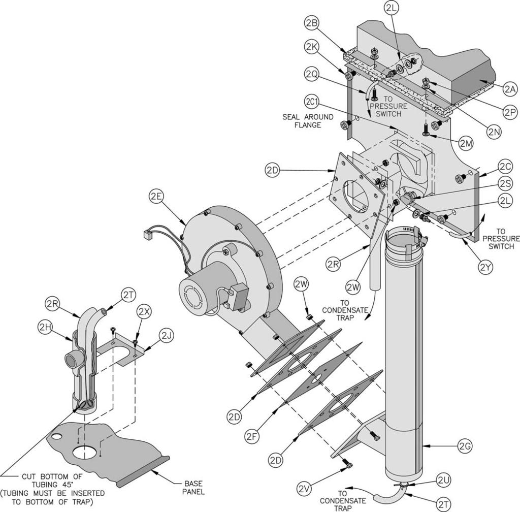
84 84
85 Key No. Description [Quantity] Part Number RV3 RV4 RV5 RV6 RV7 2. BLOWER OUTLET ORIFICE / VENT CONNECTOR ASSEMBLY 2A Canopy B Cerafelt, ½ Thick x 1 Wide [50"] [56"] [60"] [66"] [72"] C Left End Flue Cover C1 Silastic Sealant, RTV 732, Silver [A/R] D Orifice Plate Gasket, 1/8 Thick [3] E Induced Draft Blower K it (includes [3] gaskets) 2F Outlet Orifice Plate N/A 2G Vent Connector Tee & Extension H Condensate Trap J Holding Clip, Condensate Trap K Screw, Philips Pan Head, 5/16-18 x 1/ 2 [6] L Pressure Fitting, Dwyer A308 [2] M Carriage Bolt, ¼-20 x 1 [2] N Flat Washer, ¼ [8] P Hex Nut, ¼-20 [2] Q Silicone Tubing, 3/16" I.D. x 29", Black R PVC Tubing, 5/8 I. D. x 7/8 O. D. x 27½" S Spring Clamp, Nom. 7/8 Hose T PVC Tubing, 3/8 I. D. x 5/8 O.D. x 10½" U Spring Clamp, Nom. 5/8 Hose V Cap Screw, Hex Head, ¼-20 x 5/ 8 [4] W Hex Nut with Lockwasher, ¼-20 K-Locknut [8] X Sheet Metal Screw, #8 x ½ [4] Y Silicone Tubing, 3/16" I. D. x 29", Gray
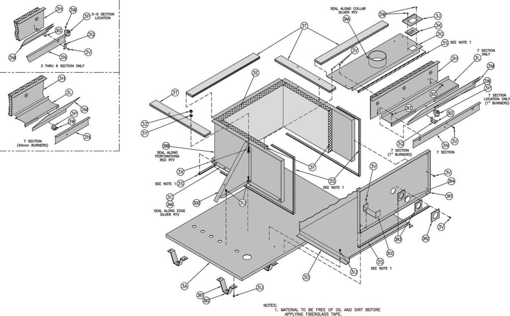
86 86
87 Key No. Description [Quantity] Part Number RV3 RV4 RV5 RV6 RV7 3. BASE ENCLOSURE ASSEMBLY 3A Base Tray [ 1] [ 1] [ 1] [ 1] B Base Leg Assembly [6] B1 Base Leg [6] B2 Nylon Glide [6] C Base Wrapper [ 1] [ 1] [ 1] [ 1] D Burner Tray (1 Inch Main Burners) Burner Tray (40mm Main Burners) [ 1] [ 1] [ 1] [ 1] E Base Rear Insulation [ 1] [ 1] [ 1] [ 1] F Base Side Insulation [2] G Enclosure Top Panel Assembly [ 1] [ 1] [ 1] [ 1] H Base Front Panel Assembly [ 1] [ 1] [ 1] [ 1] J Cover Plate, Manifold Seal K Gasket, Manifold Seal [ 1] L Combustion Air Diffuser - Support M Combustion Air Diffuser [ 1] [ 1] [ 1] [ 1] N Burner Access Panel [ 1] [ 1] [ 1] [ 1] P Flame Roll-Out Switch Q Flame Roll-Out Switch Mounting Bracket 1" Q Flame Roll-Out Switch Mounting Bracket 40mm R Enclosure Front Panel Assembly [ 1] [ 1] [ 1] [ 1] R1 Enclosure Front Panel [ 1] [ 1] [ 1] [ 1] R2 Observation Port Lens Retainer R3 Observation Port Lens Gasket [2] R4 Observation Port Lens S Fiberglass Tape Gasket, 1/8" x ½" [112"] [122"] [132"] [142"] [152"] T Ceramic Fiber Gasket, ½" x 2" [56"] [62"] [70"] [76"] [82"] U Self Tapping Screw, ¼"-20 x ½" [25] V Sheet Metal Screw, #8 x ½" [24] W Sheet Metal Screw, #8 x ¾" [3] X Self Tapping Screw, 5/16"-18 x 1¼" [4] Y Washer, 5/16" Flat [4] Z Lock Nut, 5/16"-18 [4] AA Silastic Sealant, RTV732, Silver [A/R] BB Silastic Sealant, RTV6500, Red [A/R] CC Jacket Lower Support Bar DD Base Tray Support EE Sheet Metal Screw, #10 - ½" TRS Head [3]
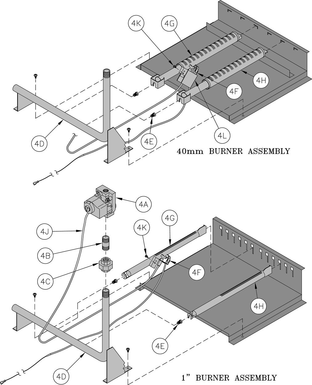
88 88
89 Key No. Description 4. BURNER ASSEMBLIES 4A 4B 4C Gas Valve (Natural Gas), Honeywell VR8204C6000 Gas Valve (Natural Gas), Honeywell VR8304P4298 Gas Valve ( L P G as), Honeywell VR8204C6018 Gas Valve ( L P G as), Honeywell VR8304P4280 [Quantity] Part Number RV3 RV4 RV5 RV6 RV7 [ 1] [ 1] [ 1] N ipple, ½" x 3" Lg. [ 1] Nipple, ¾" x 3" Lg U nion, ½" [ 1] Union, ¾" ½ " Gas Manifold (1" Burner) [ 1] [ 1] [ 1] D ¾ " Gas Manifold (1" Burner) [ 1] ½ " Gas Manifold (40mm Burner) [ 1] [ 1] [ 1] ¾ " Gas Manifold (40mm Burner) [ 1] M ain Burner Orifices (1" Burner) Standard Altitude ( ft. ) # 45 - Pink (Natural Gas) [ 3] [ 5] [ 7] [ 9] E # 48 (Natural Gas) [12] # 55 - Green (LP Gas) [ 3] [ 5] mm - Purple (LP Gas) [ 7] [ 9] /64" - Blue (LP Gas) [12] Main Burner Orifices (40mm Burner) High Altitude (2001 ft ft.) 4E # 39 (Natural Gas) [ 3] [4] [ 5] # 40 (Natural Gas) [ 2] [6] # 53 (LP Gas) [ 2] [ 3] [ 4] [ 5] [6] Main Burner Orifices (40mm Burner) High Altitude ( ft.) 4E 4F 4G 4H # 42 (Natural Gas) [ 2] [6] # 41 (Natural Gas) [ 3] [ 4] [ 5] # 54 (LP Gas) [ 2] # 53 (LP Gas) [ 3] [ 4] [ 5] [6] Pilot Assembly (Natural Gas) Pilot Assembly (LP Gas) " Burner w/bracket mm Burner w/bracket " Burner [ 2] [ 4] [ 6] [ 8] [11] mm Burner [ 1] [ 2] [ 3] [ 4] [5] J Pilot Tubing, Aluminum, 1/8" x 30" Lg. [ 1] Pilot Tubing, Aluminum, 1/8" x 40" Lg K Machine Screw, #10-32 x 3/16" Lg. (1" Burner) M achine Screw, #10-32 x 3/16" Lg. ( 40mm Burner) [2] L Pilot Enclosure (40mm Burner)
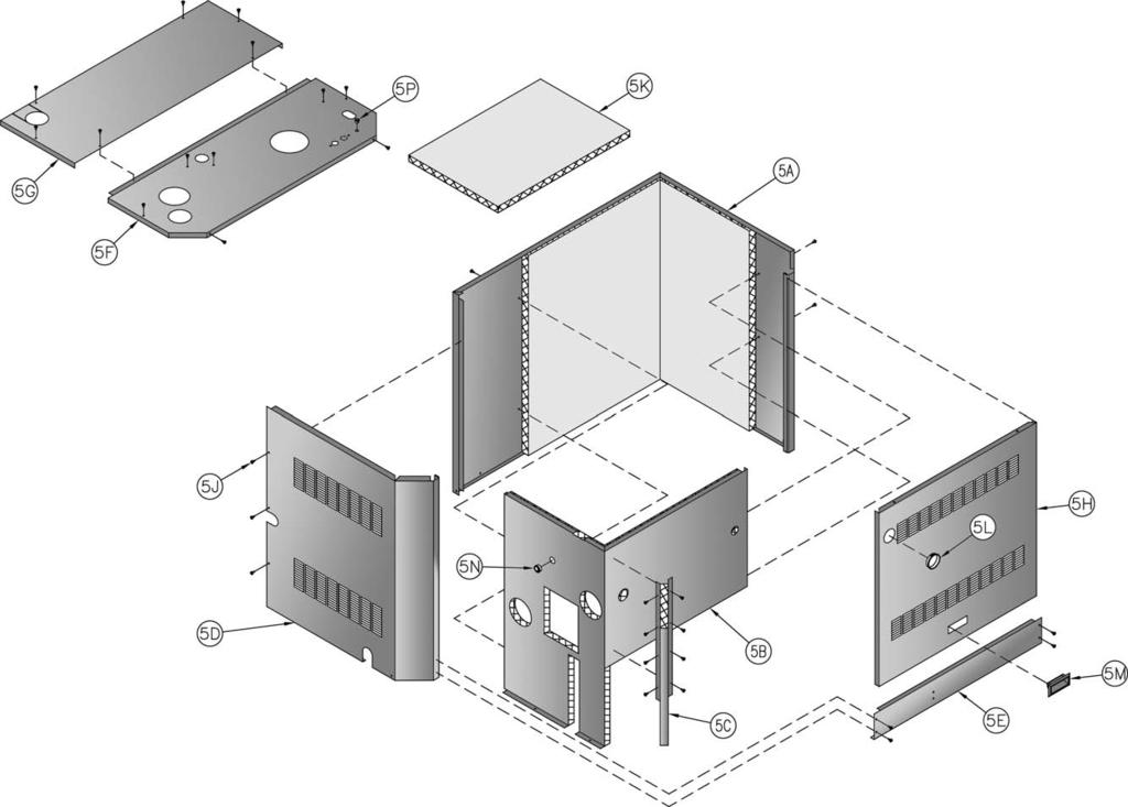
90 90
91 Key No. 5. Description JACKET PARTS [Quantity] Part Number RV3 RV4 RV5 RV6 RV7 5 Complete Jacket Assembly (less control panel) A Jacket Rear / Right Side Panel, Insulated B Jacket Vestibule Panel, Insulated C Control Panel, Insulated D Jacket Left Side Panel E Jacket Lower Front Tie Bar F Jacket Front Top Panel G Jacket Rear Top Panel H Jacket Front Removable Door J Sheet Metal Screw, #8 x ½" Lg. [38] K Insulation, Loose To p L Snap Bushing, Heyco SB M Snap-In Handle, Recessed, CT N Open/Close Bushing, Heyco #OCB P Snap-Bushing, Heyco SB
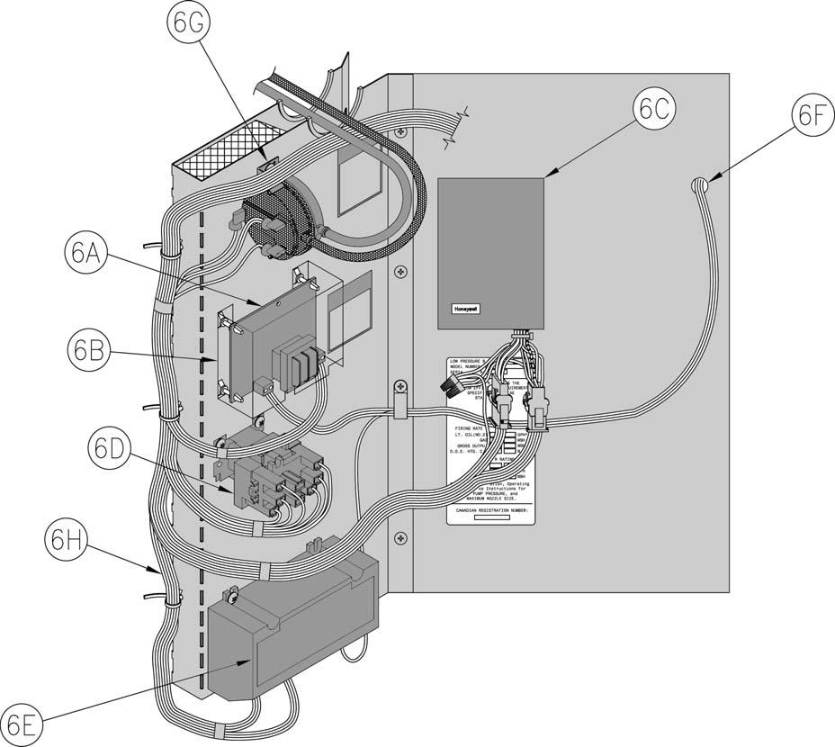
92 92
93 Key No. Description [Quantity] Part Number RV3 RV4 RV5 RV6 RV7 6. MISCELLANEOUS TRIM AND CONTROLS 6A Boiler Circulator Control, Burnham VS B Burnham VS3000/3001 Clear Cover C Aquastat, Honeywell L8148E1299, with harness D Blower Relay, Honeywell R8222U U 6E Ignition Module, Honeywell S8670E F Immersion Well, ½" NPT Honeywell A Differential Pressure Switch 6G Honeywell IS (Sea Level Ft.) Honeywell IS (Above 2000 Ft. Elevation) Honeywell IS (Sea Level Ft.) Honeywell IS (Above 2000 Ft. Elevation) Honeywell IS (Sea Level Ft.) Honeywell IS (Above 2000 Ft. Elevation) Honeywell IS (1" Burners) (Sea Level Ft.) Honeywell IS (40mm Burners) (Above 2000 Ft. Elevation) [ 1] [ 1] H Main Wiring Harness, EI
![Key No. Description 7. MISCELLANEOUS PARTS VENT CARTON ( includes items below) [Quantity] Part Number RV3 RV4 RV5 RV6 RV7 [ 1] 6050605 6050606 7 A Air Intake Assembly, 3" or 4" Dia.](/docs-images/80/80955038/images/94-0.jpg "[ 1] 6116045 6116044 7B Holding Clip, Condensate Trap 70906001 7 C Sheet Metal Screw, #8 x ½\" [2] 80860000 7 D Nipple, ¾\" x 8\" 806600221 7 E Relief Valve, ¾\" 81660319 7F Vent Terminal, Angle Cut")
94 Key No. Description 7. MISCELLANEOUS PARTS VENT CARTON ( includes items below) [Quantity] Part Number RV3 RV4 RV5 RV6 RV7 [ 1] A Air Intake Assembly, 3" or 4" Dia. [ 1] B Holding Clip, Condensate Trap C Sheet Metal Screw, #8 x ½" [2] D Nipple, ¾" x 8" E Relief Valve, ¾" F Vent Terminal, Angle Cut Straight - Through G Condensate Trap Assembly
95 DATE SERVICE RECORD SERVICE PERFORMED 95
96 DATE SERVICE RECORD SERVICE PERFORMED 96
97 DATE SERVICE RECORD SERVICE PERFORMED 97
98 Important Product Safety Information Refractory Ceramic Fiber Product Warning: This product contains refractory ceramic fibers (RCF). RCF has been classified as a possible human carcinogen. After this product is fired, RCF may, when exposed to extremely high temperature (>1800F), change into a known human carcinogen. When disturbed as a result of servicing or repair, RCF becomes airborne and, if inhaled, may be hazardous to your health. AVOID Breathing Fiber Particulates and Dust Precautionary Measures: Do not remove or replace previously fired RCF (combustion chamber insulation, target walls, canopy gasket, flue cover gasket, etc.) or attempt any service or repair work involving RCF without wearing the following protective gear: 1. A National Institute for Occupational Safety and Health (NIOSH) approved respirator 2. Long sleeved, loose fitting clothing 3. Gloves 4. Eye Protection Take steps to assure adequate ventilation. Wash all exposed body areas gently with soap and water after contact. Wash work clothes separately from other laundry and rinse washing machine after use to avoid contaminating other clothes. Discard used RCF components by sealing in an air tight plastic bag. First Aid Procedures: If contact with eyes: Flush with water for at least 15 minutes. Seek immediate medical attention if irritation persists. If contact with skin: Wash affected area gently with soap and water. Seek immediate medical attention if irritation persists. If breathing difficulty develops: Leave the area and move to a location with clean fresh air. Seek immediate medical attention if breathing difficulties persist. Ingestion: Do not induce vomiting. Drink plenty of water. Seek immediate medical attention. 98
. In addition, some jurisdictions require the use of a LWCO with a hot water boiler.")
99 XII. Low Water Cut Off (LWCO) on Hot Water Boilers When A low water cutoff is required to protect a hot water boiler when any connected heat distributor (radiation) is installed below the top of the hot water boiler (i.e. baseboard on the same floor level as the boiler). In addition, some jurisdictions require the use of a LWCO with a hot water boiler. Where The universal location for a LWCO on both gas and oil hot water boilers is above the boiler, in either the supply or return piping. The minimum safe water level of a water boiler is at the uppermost top of the boiler; that is, it must be full of water to operate safely. What Kind Typically, in residential applications, a probe type LWCO is used instead of a float type, due to their relative costs and the simplicity of piping for a probe LWCO. How to Pipe A tee is commonly used to connect the probe LWCO to the supply or return piping, as shown below. WARNING DO NOT ATTEMPT to cut factory wires to install an aftermarket Low Water Cut Off (LWCO). Only use connections specifically identified for Low Water Cut Off. In all cases, follow the Low Water Cut Off (LWCO) manufacturer's instructions. manufacturers recommend an annual inspection of the probe. How to Wire LWCO s are available in either 120 VAC or 24 VAC configurations. The 120 VAC configuration can be universally applied to both gas and oil boilers by wiring it in the line voltage service to the boiler (after the service switch, if so equipped). The presence of water in a properly installed LWCO will cause the normally open contact of the LWCO to close, thus providing continuity of the 120 VAC service to the boiler. It is recommended to supply power to the probe LWCO with the same line voltage boiler service as shown below. LWCO Location Select the appropriate size tee using the LWCO manufacturer s instructions. Often, the branch connection must have a minimum diameter to prevent bridging between the probe and the tee. Also, the run of the tee must have a minimum diameter to prevent the end of the probe from touching or being located too close to the inside wall of the run of the tee. Ideally, manual shutoff valves should be located above the LWCO and the boiler to allow for servicing. This will allow probe removal for inspection without draining the heating system. Many probe LWCO Wiring of Typical LWCO A 24 VAC LWCO is used primarily for gas fired boilers where a 24 volt control circuit exists within the boiler. However, a 24 VAC LWCO can only be used if the boiler manufacturer has provided piping and wiring connections and instructions to allow for this application. How to Test Shut off fuel supply. Lower water level until water level is BELOW the LWCO. Generate a boiler demand by turning up thermostat. Boiler should not attempt to operate. Increase the water level by filling the system. The boiler should attempt to operate once the water level is above the LWCO. 99
R5-9/09. Price - $5.00
 INSTALLATION, OPERATING AND SERVICE INSTRUCTIONS FOR R EVOLUTION GAS - FIRED BOILER As an ENERGY STAR Partner, Burnham Hydronics has determined that the Revolution Series meets the ENERGY STAR guidelines
INSTALLATION, OPERATING AND SERVICE INSTRUCTIONS PVCG SERIES GAS BOILER
 INSTALLATION, OPERATING AND SERVICE INSTRUCTIONS PVCG SERIES GAS BOILER BEFORE INSTALLATION: READ THIS MANUAL SAVE THESE INSTRUCTIONS Installing contractor and homeowner should read and be informed as
Installation and Maintenance Instructions
 Commercial & Industrial Positive Pressure or Condensing AL 29-4C Stainless Steel High Challenge Special Gas Vent Also for Natural Draft Appliances 3",4",5",6",7",8",9",10" and 12" Diameter Special Gas
Corr/Guard PRESSURE RATED VENTING SYSTEM IMPORTANT: DO NOT INSTALL WITHOUT FIRST READING THESE INSTRUCTIONS VERY CAREFULLY.
 CORR/GUARD INSTALLATION INSTRUCTIONS This symbol on the nameplate means this product is listed by Underwriters Laboratories Inc. Tested to UL1738 / CAN / ULCS636-1995 Listing No. MH26687 Testing No. 11EN
Vent Supplement Ultra-80, -105, -155, -230 & -310
 Gas-fired water boiler Vent Supplement Ultra-80, -105, -155, -230 & -310 Installation of: Vent piping Air piping with This document must only be used by a qualified heating installer/service technician.
GWS. Venting Manual. Gas-Fired Water Boilers. Hazard definitions. Contents. Venting method definitions
 GWS Gas-Fired Water Boilers Venting Manual Hazard definitions Contents Page Hazards that will cause severe personal injury, death or substantial property damage. Hazards that can cause severe personal
SMALL DIAMETER CORR/GUARD & SLEEVED CORR/GUARD
 CORR/GUARD INSTALLATION INSTRUCTIONS This symbol on the nameplate means this product is listed by Underwriters Laboratories Inc. Tested to UL1738 / CAN / ULCS636-08 Listing No. MH26687 Testing No. 11EN
INS A T LL T A ION, OPER T A ING AND SERVICE INSTRUCTIONS FOR FREEDOM CONDENSING HIGH EFFICIENCY DIRECT VENT GAS - FIRED HOT
 INSTALLATION, OPERATING AND SERVICE INSTRUCTIONS FOR FREEDOM CONDENSING HIGH EFFICIENCY DIRECT VENT GAS - FIRED HOT WATER BOILER Warning: Improper installation, adjustment, alteration, service or maintenance
2012 INTERNATIONAL FUEL GAS CODE VENTS
 2012 INTERNATIONAL FUEL GAS CODE SECTION 502 (IFGC) VENTS 502.1 General. All vents, except as provided in Section 503.7, shall be listed and labeled. Type B and BW vents shall be tested in accordance with
FLANGED CORR/GUARD CORR/GUARD INSTALLATION INSTRUCTIONS
 CORR/GUARD INSTALLATION INSTRUCTIONS This symbol on the nameplate means this product is listed by Underwriters Laboratories Inc. Tested to UL1738 / CAN / ULCS636-08 Listing No. MH26687 Testing No. 11EN
Do not use this vent pipe or fittings for venting incinerators of any kind.
 ! CAUTION! Do not use this vent pipe or fittings for venting incinerators of any kind. C.S.A. Certified For Natural Gas Or Propane Tested For 100 LBS. ASME Working Pressure For correct installation of
EUTECTIC EC-10DV Series
 EUTECTIC EC-10DV Series DIRECT VENT OIL-FIRED WATER BOILER/NO. 2 OIL VENTING INSTALLATION INSTRUCTIONS CONTENTS..........................................PAGE Basic Guidelines..........................................1
GOLD GV. Venting Supplement for 3 venting. Water Boiler Series 3 & 4
 GOLD GV Water Boiler Series 3 & 4 Venting Supplement for 3 venting Special gas vent system vent and combustion air supplement for 3 diameter venting. The following manufacturers AL29-4C Stainless Steel
Direct Exhaust Venting Kit Instructions
 CONDENSING GAS BOILER 220/299/300/399 Direct Exhaust Venting Kit Instructions Evergreen 220/299/300/399 Kit part number 383-500-769 STOP! Read before proceeding Hazard definitions The following defined
GOLD. Venting Supplement. Water Boiler Series 3 & 4. for 3" venting
 GOLD GV Water Boiler Series 3 & 4 Venting Supplement for 3" venting Special gas vent system vent and combustion air supplement for 3" diameter venting. The following manufacturers AL29-4C Stainless Steel
GAS FIRED BOILERS FOR FORCED HOT WATER VENTING ADDENDUM. ECR International Ltd. - Olsen Division P.O. Box 900 Wallaceburg, Ont.
 ODV-B GAS FIRED BOILERS FOR FORCED HOT WATER VENTING ADDENDUM ECR International Ltd. - Olsen Division P.O. Box 900 Wallaceburg, Ont. N8A5E5 TABLE OF CONTENTS HORIZONTAL PIPING... PAGES 1-10 WARNINGS...
INSTALLATION AND SERVICE MANUAL
 INSTALLATION AND SERVICE MANUAL VERTICAL COMBUSTION AIR INLET KITS CATEGORY III VENTING FOR SEPARATED COMBUSTION TUBULAR GAS FIRED UNIT HEATERS USE 5 INCH KIT FOR UNITS WITH CAPACITIES 100,000 TO 250,000
INSTALLATION AND SERVICE MANUAL
 INSTALLATION AND SERVICE MANUAL HORIZONTAL COMBUSTION AIR INLET KITS CATEGORY III VENTING FOR SEPARATED COMBUSTION TUBULAR GAS FIRED UNIT HEATERS USE 5 INCH KIT FOR UNITS WITH CAPACITIES 100,000 TO 250,000
ASX7-5-IOM-3 J
 INSTALLATION INSTRUCTIONS 5" CONCENTRIC VENT TERMINAL KIT TUBULAR GAS FIRED DIRECT SPARK PROPELLER UNIT HEATERS UNIT CONVERSION & CATEGORY III VENTING FOR SEPARATED COMBUSTION For 90,000 to 120,000 BTU/HR
Venting Supplement. Direct Vent Through-Roof or Through-Unused-Chimney. Water Boiler Series 3 & 4
 GOLD GV Water Boiler Series 3 & 4 Venting Supplement Direct Vent Through-Roof or Through-Unused-Chimney For use with Weil-McLain Through-Roof or Through- Unused-Chimney Termination Kit Kit part # 382-200-435
ASX7-4-IOM-6 J
 INSTALLATION INSTRUCTIONS 4" COMBUSTION AIR INLET KIT TUBULAR GAS FIRED DIRECT SPARK PROPELLER UNIT HEATERS UNIT CONVERSION & CATEGORY III VENTING FOR SEPARATED COMBUSTION For 30,000 to 75,000 BTU/HR SUPPLEMENT
SEPARATED COMBUSTION WARNING
 CUSTOMER AGENCY PROCESS CQS CONVERGENT QUALITY SYSTEM PRODUCT WARRANTY START-UP Form I-SDH-V (Version.5) Obsoletes I-SDH-V (Version.4) Vent Installation Applies to: Venting Requirements for PREEVA Separated-Combustion
Pellet Stove. Flex Pipe. Appliance Connector
 Installation Instructions & Owners Maintenance Guide DT-M Direct-Temp for Multi Fuel L-Vent / Vent System for Pellet, Corn and other Bio-Fuel Burning Appliances Introduction Direct-Temp for Multi-Fuel
200i. Vent/air manual. Installation instructions for vent and air piping. Also read and follow: 200i Boiler manual 200i Control manual
 M2i-VAM-2 Cast iron condensing boiler 200i Vent/air manual Installation instructions for vent and air piping Also read and follow: 200i Boiler manual 200i Control manual This manual is intended only for
Installation & Maintenance Instructions
 Installation & Maintenance Instructions Listed & Tested to UL641, ULC-S609, ULC/ORD C441 AMERIVENT Model PVP Pellet Pipe Plus Vent Connector for Pellet-Fuel Appliances and Other Low-Temperature Applications
TRIAD Boiler Systems, Inc Atlantic Drive, Unit 2 West Chicago, IL
 TRIIUMPH SERIIES AIIR SUPPLY AND VENTIING GUIIDE C.S.A Design-Certified Complies with ANSI Z21.13/CSA 4.9 Gas-Fired Low Pressure Steam & Hot Water Boilers ASME Code Section IV C.S.A Design-Certified Complies
INSTALLATION, OPERATING AND SERVICE INSTRUCTIONS EVA SERIES BOILER
 INSTALLATION, OPERATING AND SERVICE INSTRUCTIONS EVA SERIES BOILER MODULATION Price - $3.00 A SM File Number MH25585 H E For Service and repairs to the heating plant, call your heating contractor. When
INSTALL T A ION, OPER T A ING AND SERVICE INSTRUCTIONS FOR INDEPENDENCE PV GAS - FIRED BOILER
 INSTALLATION, OPERATING AND SERVICE INSTRUCTIONS FOR I NDEPENDENCE PV GAS - FIRED BOILER 9700609 For service or repairs to boiler, call hour heating contractor. When seeking information on boiler, provide
R9-9/10 Price - $5.00
 INSTALLATION, OPERATING AND SERVICE INSTRUCTIONS FOR ALPINE CONDENSING HIGH EFFICIENCY DIRECT VENT GAS - FIRED HOT WATER BOILER 9700609 As an ENERGY STAR Partner, Burnham by U.S. Boiler Company has determined
Installation Instructions T 9822 Gas Dryer. en - US, CA. To prevent accidents
 Installation Instructions T 9822 Gas Dryer To prevent accidents en - US, CA and appliance damage read these instructions before installation or use. M.-Nr. 07 431 110 2 WARNING For your safety the information
Mighty Venter Power Vent System
 Installation and Operation Instructions Document 7008B Installation and Operation Instructions for Mighty Venter Power Vent System Models MV2, MV3, MV4, and MV5 for Mighty Therm Sizes 500-1825 FOR YOUR
INSTALL T A ION, OPER T A ING AND SERVICE INSTRUCTIONS FOR INDEPENDENCE PV GAS - FIRED BOILER
 INSTALLATION, OPERATING AND SERVICE INSTRUCTIONS FOR I NDEPENDENCE PV GAS - FIRED BOILER 9700609 For service or repairs to boiler, call hour heating contractor. When seeking information on boiler, provide
CAST 92. Boilers. As an ENERGY STAR Partner, PB Heat, LLC has determined that this product meets the ENERGY STAR guidelines for energy efficiency.
 Peerless Gas CAST 92 Boilers As an ENERGY STAR Partner, PB Heat, LLC has determined that this product meets the ENERGY STAR guidelines for energy efficiency. Installation, Operation & Maintenance Manual
Power-Fin 4:1 HOT WATER HEATING BOILERS DOMESTIC HOT WATER SUPPLY BOILERS 1,500,000, 1,700,000 and 2,000,000 Btu/hr MODELS
 PBE/PFE-i&s-03 INSTALLATION AND SERVICE MANUAL Power-Fin 4:1 HOT WATER HEATING BOILERS DOMESTIC HOT WATER SUPPLY BOILERS 1,500,000, 1,700,000 and 2,000,000 Btu/hr MODELS FIG. 1 Front View 1,500,000-2,000,000
Z-VENT MODEL SVE SERIES III INSTALLATION AND MAINTENANCE INSTRUCTIONS
 Z-VENT MODEL SVE SERIES III INSTALLATION AND MAINTENANCE INSTRUCTIONS 3 & 4 SPECIAL STAINLESS STEEL VENTING SYSTEM FOR GAS BURNING APPLIANCES CATEGORY I, II, III, & IV TESTED AND LISTED BY UNDERWRITERS
INSTALLATION, OPERATING AND SERVICE INSTRUCTIONS EVS SERIES MODULATING BOILER
 INSTALLATION, OPERATING AND SERVICE INSTRUCTIONS EVS SERIES MODULATING BOILER Price - $3.00 File Number MH25585 For Service and repairs to the heating plant, call your heating contractor. When seeking
VENTING CLEARANCES. BBT NORTH AMERICA Bosch Group. Bosch Water Heating 340 Mad River Park, Waitsfield, VT TWH-V-26 page 1 of 6 rev 01/06
 page 1 of 6 VENTING CLEARANCES The vents should not be obstructed and all joints properly fitted. Floors, ceilings and walls must be cut or framed to provide necessary clearance to vents. Metal strippings
PVC, CPVC, PP & SS Vent Supplement
 PVC, CPVC, PP & SS Vent Supplement L I S T E D This document is intended to be used by a qualified heating contractor or service technician. Read all instructions within this document and within the PRESTIGE
SAFE DRINKING WATER AND TOXIC ENFORCEMENT ACT
 Installation instructions for your new Spacemaker Laundry WSM2780 Gas Before you begin Read these instructions completely and carefully. IMPORTANT OBSERVE ALL GOVERNING CODES AND ORDINANCES. Note to Installer
Aqua Balance. Direct Exhaust Venting Kit Instructions
 Aqua Balance WMB-155H and WMB-155C Wall Mount Gas-Fired Heating Only Boiler & Combination Boiler Heating and Domestic Hot Water Direct Exhaust Venting Kit Instructions AquaBalance TM WMB-155H & WMB-155C
/08 Price - $5.00
 INSTALLATION, OPERATING AND SERVICE INSTRUCTIONS FOR ALPINE CONDENSING HIGH EFFICIENCY DIRECT VENT GAS - FIRED HOT WATER BOILER As an ENERGY STAR Partner, Burnham Hydronics has determined that the Alpine
INSTALLER'S GUIDE MASONRY CHIMNEY VENT KIT WARNING: BAYVENT800B 18- CH23D2-05
 INSTALLER'S GUIDE IMPORTANT This Document is customer property and is to remain with this unit. Please return to service information pack upon completion of work. Model: BAYVENT800B For use with Category
SEPARATED COMBUSTION. General WARNING
 Form I-UD-V-SC (09-17) Obsoletes Form I-UD-V-SC (Version 05-17) APPLIES TO: Venting Requirements for Model UDAS and Model UDBS and Instructions for Combustion Air Inlet / Vent Terminal Options CC6 and
PVE SERIES POWER VENTER SYSTEM MANUAL
 PVE SERIES POWER VENTER SYSTEM MANUAL Contents Page I. Typical Venting System Components 2 II. System Operation 3 III. Power Venter Sizing 3,4 IV. Installation Safety Instructions 5,6 V. Installation of
CHAPTER 8 CHIMNEYS AND VENTS
 CHAPTER 8 CHIMNEYS AND VENTS SECTION 801 GENERAL 801.1 Scope. This chapter shall govern the installation, maintenance, repair and approval of factory-built chimneys, chimney liners, vents and connectors.
POWER VENT. Standard Power Vent, Fan Type Unit Heaters: Standard Power Vent, Blower Type Unit Heaters: General WARNING WARNING. Model UDAP & Model APD
 General APPLIES TO: Standard Power Vent, Fan Type Unit Heaters: Model UDAP & Model APD Standard Power Vent, Blower Type Unit Heaters: Model UDBP Form I-UD&APD Series-V-PV (05-17) Obsoletes I-UD&APD Series-V-PV
Installation Instructions
 Residential Gas Furnaces Installation Instructions *RA Full Size Series 80+ High Efficiency Upflow/Horizontal *RK Full Size Series 80+ High Efficiency Downflow *RA 80+ Upflow/Horizontal *RK 80+ Downflow!
CHIMNEYS AND VENTS CHAPTER 8
 CHAPTER 8 CHIMNEYS AND VENTS SECTION 801 GENERAL 801.1 Scope. This chapter shall govern the installation, maintenance, repair and approval of factory-built chimneys, chimney liners, vents and connectors.
INSTALLATION AND SERVICE MANUAL
 INSTALLATION AND SERVICE MANUAL HOT WATER HEATING BOILERS Domestic Water Heaters 150,000-300,000 Btu/hr MODELS EB-EW-I-S-09 IMPORTANT: This is a gas appliance and should be installed by a licensed electrician
CWD Series. Gas-Fired Direct Vent Hot Water Boilers INSTALLATION INSTRUCTIONS These instructions must be affixed on or adjacent to the boiler
 D E S I G N E D T O L E A D CWD Series Gas-Fired Direct Vent Hot Water Boilers INSTALLATION INSTRUCTIONS These instructions must be affixed on or adjacent to the boiler Models: CWD060 CWD083 CWD110 CWD138
Ventis Direct Vent. Installation Instructions
 entis Direct ent Installation Instructions A MAJOR CAUSE OF CHIMNEY RELATED FIRES IS FAILURE TO MAINTAIN REQUIRED CLEARANCES (AIR SPACES), TO COMBUSTIBLE MATERIALS. IT IS OF THE UTMOST IMPRORTANCE THAT
Venting Supplement Saf-T Vent 3" venting Special gas vent system vent and combustion air supplement for 3" diameter venting Hazard definitions
 GOLD GV Water Boiler Series 3 & 4 Venting Supplement 3" venting Special gas vent system vent and combustion air supplement for 3" diameter venting Heat-Fab, Inc. AL29-4C Stainless Steel Special Gas Vent
GENERAL BASIC INSTALLATION INSTRUCTIONS INDIRECT GAS FIRED WATER HEATERS PARKER BOILER CO.
 GENERAL BASIC INSTALLATION INSTRUCTIONS INDIRECT GAS FIRED WATER HEATERS PARKER BOILER CO. GBI 210 3C For a proper installation and in order to receive the best in operating life and efficiency from your
INSTALLATION, OPERATING AND SERVICE INSTRUCTIONS EVO SERIES BOILER
 INSTALLATION, OPERATING AND SERVICE INSTRUCTIONS EVO SERIES BOILER ON/OFF AND MODULATION, OUTDOOR Price - $3.00 A SM File Number MH25585 H E For Service and repairs to the heating plant, call your heating
GENERAL BASIC INSTALLATION INSTRUCTIONS DIRECT FIRED HOT WATER BOILERS PARKER BOILER CO.
 GENERAL BASIC INSTALLATION INSTRUCTIONS DIRECT FIRED HOT WATER BOILERS PARKER BOILER CO. GBI 201-5 3C For a proper installation and in order to receive the best in operating life and efficiency from your
Vertical Termination Part No: 3CGRVT 16 7/8" 18 Vent Pipe Extension Part No: 3CG18 9 7/8" Wall Hanger Part No: 3CGWH 7 7/8" 7 3/8"
 Corr/Guard Direct Vent Water Heater Vent/Air Intake System Installation and service must be performed by a qualified installer, service agency or the gas supplier. Installation must meet all state and
USER S INFORMATION MANUAL
 USER S INFORMATION MANUAL UPFLOW & DOWNFLOW/HORIZONTAL CONDENSING GAS FURNACES SAFETY Recognize this symbol as an indication of Important Safety Information If not installed, operated and maintained in
CHAPTER 8 CHIMNEYS AND VENTS
 CHAPTER 8 CHIMNEYS AND VENTS SECTION 801 GENERAL 801.1 Scope. This chapter shall govern the installation, maintenance, repair and approval of factory-built chimneys, chimney liners, vents and connectors.
5"x 8" DIRECT VENT INSTALLATION INSTRUCTIONS FOR DECORATIVE GAS APPLIANCES AND DIRECT VENT HEATERS APPLICATION
 5"x 8" DIRECT VENT INSTALLATION INSTRUCTIONS FOR DECORATIVE GAS APPLIANCES AND DIRECT VENT HEATERS APPLICATION These instructions apply to the Simpson Dura-Vent 5"x 8" Direct Vent System. This venting
Inspection Checklist Mechanical Final
 Property Owner Name: Property Address: Property Parcel Number: Inspectors Name: Review Date: Permits and Plans 1. Job address is posted in a visible location. (R319.1) 2. Permit and approved plans, and
INSTALLATION INSTRUCTIONS
 INSTALLATION INSTRUCTIONS HORIZONTAL COMBUSTION AIR INLET KITS CATEGORY III VENTING FOR SEPARATED COMBUSTION TUBULAR GAS FIRED DUCT FURNACES USE 5 KIT FOR UNITS WITH CAPACITIES 100,000 TO 200,000 BTU/HR
TYPE L VENT / VENT SYSTEM FOR PELLET BURNING APPLIANCES
 INSTALLATION INSTRUCTIONS & MAINTENANCE GUIDE TYPE L VENT / VENT SYSTEM FOR PELLET BURNING APPLIANCES LISTED TO ULC-S609 & UL641 A MAJOR CAUSE OF VENT RELATED FIRES IS FAILURE TO MAINTAIN REQUIRED CLEARANCES
SEPARATED COMBUSTION. General
 Form I-UD-V-SC (Version D) Obsoletes Form I-UD-V-SC (Version C) APPLIES TO: Venting Requirements for Model UDAS and Model UDBS and Instructions for Inlet / Vent Terminal Options CC6 and CC2 General This
Gas-Fired Fan Assisted Hot Water Boilers INSTALLATION INSTRUCTIONS These instructions must be affixed on or adjacent to the boiler
 D E S I G N E D T O L E A D BWF Series Gas-Fired Fan Assisted Hot Water Boilers INSTALLATION INSTRUCTIONS These instructions must be affixed on or adjacent to the boiler Models: BWF061 BWF095 BWF128 BWF162
GOLD GV. Venting Supplement. Water boiler Series 3. Special gas vent system vent and combustion air supplement. Hazard definitions.
 GOLD GV Water boiler Series 3 Venting Supplement Special gas vent system vent and combustion air supplement ProTech Systems AL29-4C Stainless Steel Special Gas Vent System may be used in new installations
Direct Vent Training & Installation Instructions for Venting 40/50 gallon models Telescoping Vent Kit (standard)
") Choosing Location of the water heater This water heater is of the direct vent design. It takes all of its fresh air for combustion from outside the building which it is installed. It also vents the combustion
Choosing Location of the water heater This water heater is of the direct vent design. It takes all of its fresh air for combustion from outside the building which it is installed. It also vents the combustion
INSTALLATION AND OPERATING INSTRUCTIONS TABLE OF CONTENTS IMPORTANT
 C US This manual must be left with owner and should be hung on or adjacent to the boilerfor reference. COMMON VENTING MODELS CHS-300 through CHS-399 INSTALLATION AND OPERATING INSTRUCTIONS TABLE OF CONTENTS
INSTALLATION, OPERATING AND SERVICE INSTRUCTIONS EVCA SERIES CONDENSING BOILER
 INSTALLATION, OPERATING AND SERVICE INSTRUCTIONS EVCA SERIES CONDENSING BOILER Price - $3.00 A SM File Number MH25585 H E For service and repairs to the heating plant, call your heating contractor. When
Inspection Checklist Mechanical Rough in
 Property Owner Name: Property Address: Permit Number: Inspectors Name: Review Date: Permits and Plans 1. Job address is posted in a visible location. (R319.1) 2. Permit and approved plans are on site and
CQS POWER VENT. General. Venting Requirements. Venting Instructions PREEVA Indoor, Power-Vented Heater Model PDH
 Applies to: Form I-PDH-V Venting Instructions PREEVA Indoor, Power-Vented Heater Model PDH CUSTOMER AGENCY PROCESS CQS CONVERGENT QUALITY SYSTEM PRODUCT WARRANTY START-UP Power-Vent Indoor Model PDH General
Installation and Maintenance Instructions
 Installation and Maintenance Instructions Saf-T Vent Model EZ Seal and Model GC Single Wall AL 29-4C Stainless Steel Gas Vent Connector Chimney Liner & Special Gas Vent (USA) / Type BH Vent Class I/II
BDM Direct Vent systems are for use with direct vent gas fired appliances.
 INSTALLATION INSTRUCTIONS Pro-Form DIRECT VENT SYSTEM Tested to ANSI Z21.88-2009 /CSA 2.33-2009 REPORT # 369-P-02b-6.5 Read through all venting and appliance instructions before beginning your installation.
INSTALLATION INSTRUCTIONS
 INSTALLATION INSTRUCTIONS VERTICAL COMBUSTION AIR INLET KITS CATEGORY III VENTING FOR SEPARATED COMBUSTION TUBULAR GAS FIRED DUCT FURNACES USE 5" KIT FOR UNITS WITH CAPACITIES 100,000 TO 200,000 BTU/HR
Installation Instructions
 Installation Instructions Type B Gas Vent Model E/R 3" 8" ECCO TYPE B GAS VENT AND ACCESSORIES ARE FOR USE ONLY WITH LISTED CATEGORY 1 GAS-FIRED APPLIANCES OR APPLIANCES LISTED FOR USE WITH TYPE B GAS
Internet Version for Reference Only INDUCED DRAFT COMMERCIAL WATER HEATERS SUPPLEMENT INSTRUCTIONS TO PART #
 INDUCED DRAFT COMMERCIAL WATER HEATERS SUPPLEMENT INSTRUCTIONS TO PART #238-39387-00 THIS INSTRUCTION SUPPLEMENT IS ONLY INTENDED TO GIVE INSTALLATION INSTRUCTIONS AND INFORMATION RELATED TO THE INDUCED
Installation Instructions
 Installation Instructions Gas & Electric Dryer Before beginning installation, carefully read these instructions. This will simplify the installation and ensure the dryer is installed correctly and safely.
FOR YOUR SAFETY WARNING FOR YOUR SAFETY. high efficiency, separated combustion gas-fired unit heaters models PTC and BTC
 6-563.7 5H0807150000 November, 2014 Model PTC installation and service manual high efficiency, separated combustion gas-fired unit heaters models PTC and BTC WARNING 1. Improper installation, adjustment,
INSTALLATION INSTRUCTIONS FOR THROUGH-THE-WALL VENTING COMPONENTS
 OIL FIRED WATER HEATER INSTALLATION AND OPERATING INSTRUCTIONS Read these instructions thoroughly before starting INSTALLATION INSTRUCTIONS FOR THROUGH-THE-WALL VENTING COMPONENTS These instructions apply
Vent and air piped through a side wall (concentric termination)
") Vent and air piped through a side wall (concentric termination) Read before proceeding The vent piping operates with positive pressure. The vent piping must be completely sealed and securely supported.
Vent and air piped through a side wall (concentric termination) Read before proceeding The vent piping operates with positive pressure. The vent piping must be completely sealed and securely supported.
XEB Series II. Models XEB-2 XEB-3 XEB-4 XEB-5 XEB-6 XEB-7. Gas-Fired Hot Water Induced Draft Boilers INSTALLATION, OPERATION & MAINTENANCE MANUAL
 Models XEB-2 XEB-3 XEB-4 XEB-5 XEB-6 XEB-7 XEB Series II Gas-Fired Hot Water Induced Draft Boilers INSTALLATION, OPERATION & MAINTENANCE MANUAL C.S.A. Certified For Natural Gas Or Propane Tested For 50
By Bernard Dalsin Mfg. Co. Installation and Operating Instructions Read these instructions and keep them for future reference
 By Bernard Dalsin Mfg. Co. 5205 208 th St Farmington MN 55024 L-VENT TYPE 3 "and 4" Factory-built venting system for wood pellet, corn or biomass and low-temperature gas or liquid fuel appliances Installation
Models CB-45 through CB-180 Cast-iron Hot Water Boilers Gas-fired Sealed Combustion Direct Vent, Category I, or Category IV Venting Flexibility
 CONCEPT 21 Models CB-45 through CB-180 Cast-iron Hot Water Boilers Gas-fired Sealed Combustion Direct Vent, Category I, or Category IV Venting Flexibility INSTALLATION AND OPERATING INSTRUCTIONS Contents.................................Page
User s Information Manual
 Gas-fired Water boiler Series 2 NOTICE: Series 1/Series 2 identification Read the boiler rating plate to determine the series number. The rating plate is located on the right side of the boiler. User s
POWER VENTER. Model: PVE Series
 POWER VENTER Model: PVE Series CONTENTS Typical Venting System Components... System Operation... Power Venter Sizing... Installation Safety Instructions... Installation of Power Venter... Connecting Power
! WARNING: FIRE OR EXPLOSION HAZARD. Applies to: Model SC, Separated-Combustion Duct Furnace. Model SC INSTALLATION / OPERATION / MAINTENANCE
 Form I-SC (05-15) Obsoletes Form I-SC (12-14) INSTALLATION / OPERATION / MAINTENANCE Applies to: Model SC, Separated-Combustion Duct Furnace Model SC CUSTOMER CQS AGENCY CONVERGENT QUALITY SYSTEM PRODUCT
INSTALLATION AND SERVICE MANUAL. Hot Water Heating Boilers Domestic Hot Water Supply Boilers 399, ,000 Btu/hr Models
 INSTALLATION AND SERVICE MANUAL CF/CH(P)i&S-02 Hot Water Heating Boilers Domestic Hot Water Supply Boilers 399,999 750,000 Btu/hr Models Installation and service must be performed by a qualified service
SVB SERIES II. Gas-Fired Hot Water Induced Draft Boilers. Models SVB-2 SVB-3 SVB-4 SVB-5 SVB-6 SVB-7 INSTALLATION, OPERATION & MAINTENANCE MANUAL
 SVB SERIES II Gas-Fired Hot Water Induced Draft Boilers Models SVB-2 SVB-3 SVB-4 SVB-5 SVB-6 SVB-7 INSTALLATION, OPERATION & MAINTENANCE MANUAL C.S.A. Certified For Natural Gas Or Propane Tested For 50
Installation instructions for the T 9820 Gas Dryer
 Installation instructions for the T 9820 Gas Dryer The T 9820 gas dryer is only approved for use in the USA and Canada. It is not approved for use in Mexico. To prevent accidents en - US, CA and machine
101 S. George St 116 E Gas Ave York, PA York, PA (717) (717)
 (717)") City of York Qdot Engineering 101 S. George St 116 E Gas Ave York, PA 17405 York, PA 17405 (717) 849-2329 (717) 744-8315 INSPECTION CHECKLIST Residential Mechanical 2009 Codes This checklist is intended
City of York Qdot Engineering 101 S. George St 116 E Gas Ave York, PA 17405 York, PA 17405 (717) 849-2329 (717) 744-8315 INSPECTION CHECKLIST Residential Mechanical 2009 Codes This checklist is intended
Installation and Operation Instructions Manual
 To the Installer: Please attach these instructions next to the water heater. To the Consumer: Please read these and all component instructions and keep for future reference. Installation and Operation
HIGH-EFFICIENCY DOWNFLOW / HORIZONTAL FURNACE INSTALLER'S INFORMATION MANUAL
 HIGH-EFFICIENCY DOWNFLOW / HORIZONTAL FURNACE INSTALLER'S INFORMATION MANUAL DESI GN C E R TI F I ED DOWNFLOW POSITION SHOWN ATTENTION, INSTALLER! After installing the furnace, show the user how to turn
LGB Gas fired boiler
 LGB Gas fired boiler Control Supplement LGB-5 Series 2 Propane gas CSD-1 Control System Part Number 550-110-682/0304 Please read this page first Hazard definitions To the installer... The following terms
DANGER Indicates a hazardous situation which, if not avoided, will result in death or serious injury.
 Installation Gas Dryers Instructions 02 DESIGN CERTIFIED Questions? Call 800.561.3344 or visit our Web site at: GEAppliances.ca This is the safety alert symbol. This symbol alerts you to potential hazards
Adopting Agency BSC SFM. Adopt Entire Chapter X X X X X X X X X X Adopt Entire Chapter as amended (amended sections listed below)
") CALIFORNIA MECANICAL CODE MATRIX ADOPTION TABLE CAPTER CIMNEY AND VENTS Adopting Agency BSC SFM CD DSA OSPD 1 1/AC AC SS SS/CC 1 4 Adopt Entire Chapter X X X X X X X X X X Adopt Entire Chapter as amended
CALIFORNIA MECANICAL CODE MATRIX ADOPTION TABLE CAPTER CIMNEY AND VENTS Adopting Agency BSC SFM CD DSA OSPD 1 1/AC AC SS SS/CC 1 4 Adopt Entire Chapter X X X X X X X X X X Adopt Entire Chapter as amended
INSTALLATION AND SERVICE MANUAL
 INSTALLATION AND SERVICE MANUAL CHF2-i&s-02 Hot Water Heating Boilers Domestic Hot Water Supply Boilers 300,000 and 990,000 2,070,000 BTU Models Installation and service must be performed by a qualified
Section 42. Lead Paint Risk Factor NONE WATER HEATER STORAGE GAS
 WATER HEATER STORAGE GAS Lead Paint Risk Factor NONE TABLE OF CONTENTS PART 1: INSTALLATION REQUIREMENTS FOR CONVENTIONAL HOMES... 1 WATER HEATER REPAIR... 1 1. APPLIANCE REPAIR... 1 WATER HEATER INSTALLATION...
ML180UH SERIES GAS FURNACE WARNING WARNING
 2017 Lennox Industries Inc. Dallas, Texas, USA 506525-01 04/2017 Supersedes 10/2015 ML180UH SERIES GAS FURNACE Improper installation, adjustment, alteration, service or maintenance can cause property damage,
Saf-T Vent SC Plus/SC 316
 Installation and Maintenance Instructions Saf-T Vent SC Plus/SC 316 Double Wall One Inch Air Space Special Gas Vent For Venting Residential and Light Commercial Appliances Category I,II,III,IV Appliances
GB162 Concentric Horizontal Vent Kit
 GB162 Concentric Horizontal Vent Kit FOR BUDERUS GB162 SERIES BOILERS Installation Instructions 2 Concentric Horizontal Vent Kit Installation Manual Data subject to change Bosch Thermotechnology Corp.
Gas-Fired Fan Assisted Hot Water Boilers INSTALLATION INSTRUCTIONS These instructions must be affixed on or adjacent to the boiler
 D E S I G N E D T O L E A D BWF Series Gas-Fired Fan Assisted Hot Water Boilers INSTALLATION INSTRUCTIONS These instructions must be affixed on or adjacent to the boiler Models: BWF061 BWF095 BWF128 BWF162